A Substitute Vision System for Providing 3D Perception and GPS ...
A Substitute Vision System for Providing 3D Perception and GPS ...
A Substitute Vision System for Providing 3D Perception and GPS ...

You also want an ePaper? Increase the reach of your titles
YUMPU automatically turns print PDFs into web optimized ePapers that Google loves.
A <strong>Substitute</strong> <strong>Vision</strong> <strong>System</strong> <strong>for</strong> <strong>Providing</strong> <strong>3D</strong> <strong>Perception</strong><br />
<strong>and</strong> <strong>GPS</strong> Navigation via Electro-Tactile Stimulation<br />
Abstract<br />
Simon Meers <strong>and</strong> Koren Ward<br />
School of IT <strong>and</strong> Computer Science<br />
University of Wollongong<br />
Wollongong, NSW, Australia, 2522<br />
meers@uow.edu.au, koren@uow.edu.au<br />
This paper describes a novel approach <strong>for</strong> enabling the blind to achieve obstacle avoidance <strong>and</strong> navigation in<br />
outdoor environments with the aid of visual sensors, <strong>GPS</strong> <strong>and</strong> electro-tactile stimulation. The electro-neural<br />
vision system (ENVS) works by extracting a depth map from stereo cameras by measuring the disparity between<br />
the stereo images. This range data is then delivered to the fingers via electro-neural stimulation to indicate to the<br />
user the range of objects being viewed by the cameras. To perceive the location of obstacles <strong>and</strong> the <strong>3D</strong> structure<br />
of the environment the user imagines that the h<strong>and</strong>s are held in the direction viewed by the cameras, with fingers<br />
extended, <strong>and</strong> the amount of stimulation felt by each finger indicates the range of objects in the direction pointed<br />
at by each finger. Also, the relative location of significant l<strong>and</strong>marks is determined using <strong>GPS</strong> <strong>and</strong> stored <strong>GPS</strong><br />
coordinates <strong>and</strong> delivered to the fingers via encoded pulses when the l<strong>and</strong>marks are in the field of view of the<br />
stereo cameras. This intuitive means of perceiving the <strong>3D</strong> structure of the environment <strong>and</strong> the location of<br />
l<strong>and</strong>marks in real time effectively enables the user to navigate the environment without use of the eyes or other<br />
blind aids. Experimental results are provided demonstrating the potential that this <strong>for</strong>m of <strong>3D</strong> environment<br />
perception has at enabling the user to achieve localisation, obstacle avoidance <strong>and</strong> navigation without using the<br />
eyes.<br />
Keywords: substitute vision, TENS, electro-tactile, electro-neural vision, stereo cameras, disparity, <strong>GPS</strong><br />
1 Introduction<br />
It is estimated there are 37 million blind people<br />
worldwide [1]. Consequently, blindness not only<br />
represents a severe cognitive h<strong>and</strong>icap, but also a<br />
significant burden on the global community. To<br />
address this problem, we have been experimenting<br />
with electro-tactile user interfaces, stereo video<br />
cameras <strong>and</strong> <strong>GPS</strong> <strong>for</strong> providing the user with useful<br />
<strong>3D</strong> perception of the environment <strong>and</strong> l<strong>and</strong>marks<br />
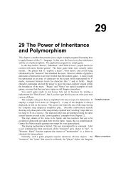
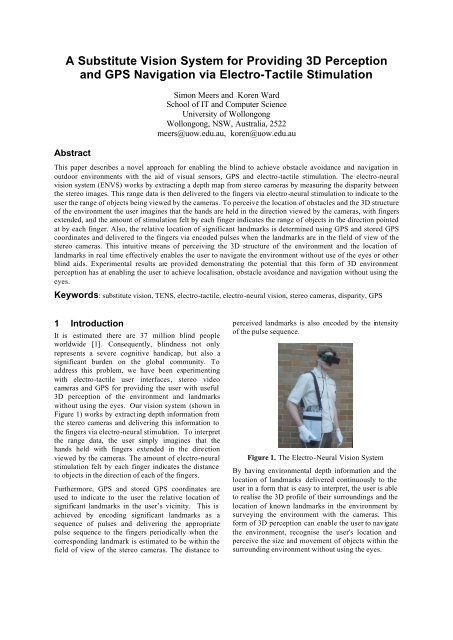
without using the eyes. Our vision system (shown in<br />
Figure 1) works by extracting depth in<strong>for</strong>mation from<br />
the stereo cameras <strong>and</strong> delivering this in<strong>for</strong>mation to<br />
the fingers via electro-neural stimulation. To interpret<br />
the range data, the user simply imagines that the<br />
h<strong>and</strong>s held with fingers extended in the direction<br />
viewed by the cameras. The amount of electro-neural<br />
stimulation felt by each finger indicates the distance<br />
to objects in the direction of each of the fingers.<br />
Furthermore, <strong>GPS</strong> <strong>and</strong> stored <strong>GPS</strong> coordinates are<br />
used to indicate to the user the relative location of<br />
significant l<strong>and</strong>marks in the user’s vicinity. This is<br />
achieved by encoding significant l<strong>and</strong>marks as a<br />
sequence of pulses <strong>and</strong> delivering the appropriate<br />
pulse sequence to the fingers periodically when the<br />
corresponding l<strong>and</strong>mark is estimated to be within the<br />
field of view of the stereo cameras. The distance to<br />
perceived l<strong>and</strong>marks is also encoded by the intensity<br />
of the pulse sequence.<br />
Figure 1. The Electro-Neural <strong>Vision</strong> <strong>System</strong><br />
By having environmental depth in<strong>for</strong>mation <strong>and</strong> the<br />
location of l<strong>and</strong>marks delivered continuously to the<br />
user in a <strong>for</strong>m that is easy to interpret, the user is able<br />
to realise the <strong>3D</strong> profile of their surroundings <strong>and</strong> the<br />
location of known l<strong>and</strong>marks in the environment by<br />
surveying the environment with the cameras. This<br />
<strong>for</strong>m of <strong>3D</strong> perception can enable the user to navigate<br />
the environment, recognise the user's location <strong>and</strong><br />
perceive the size <strong>and</strong> movement of objects within the<br />
surrounding environment without using the eyes.
In Section 2 of this paper we provide a brief review of<br />
previous work done on artificial or substitute vision<br />
systems <strong>and</strong> <strong>GPS</strong> aids <strong>for</strong> the blind. In Section 3 we<br />
provide implementation details of the Electro Neural<br />
<strong>Vision</strong> <strong>System</strong> (ENVS) with respect to <strong>3D</strong> perception<br />
<strong>and</strong> l<strong>and</strong>mark recognition. In Section 4 we provide the<br />
results of experiments we have conducted with the<br />
ENVS to demonstrate its possible use <strong>for</strong> assisting the<br />
blind to navigate outdoor environments. Finally, we<br />
provide concluding remarks <strong>and</strong> a brief description of<br />
further work to be done.<br />
2 Background<br />
Bionic vision in the <strong>for</strong>m of artificial silicon retinas or<br />
external cameras that stimulate the retina, optic nerve<br />
or visual cortex via tiny implanted electrodes are<br />
currently under development (see [2], [3] & [4]).<br />
Currently, the only commercially available artificial<br />
vision implant is the Dobelle Implant [5]. This device<br />
provides visual perception in the <strong>for</strong>m of points of<br />
light that bear little resemblance to the surrounding<br />
environment. Even if more successful results are<br />
achieved with implants in the not so distant future,<br />
many blind people may not benefit from implants due<br />
to their high cost <strong>and</strong> the expertise required to<br />
surgically implant the device. Some <strong>for</strong>ms of<br />
blindness (eg. brain or optic nerve damage) may also<br />
be unsuitable <strong>for</strong> implants.<br />
In addition to bionic vision implants, a number of<br />
wearable devices have been developed <strong>for</strong> providing<br />
the blind with some means of sensing or visualizing<br />
the environment. For example, Meijer’s vOICe [6]<br />
compresses a camera image into a coarse 2D array of<br />
greyscale values <strong>and</strong> delivers this in<strong>for</strong>mation to the<br />
ears as a sequence of sounds with varying frequency.<br />
Considerable work on sonar mobility aids <strong>for</strong> the<br />
blind has been done by Kay [7]. Kay’s systems<br />
deliver frequency modulated sounds, which represent<br />
an object’s distance by the pitch of the generated<br />
sound <strong>and</strong> the object’s surface texture by the timbre of<br />
the sound delivered to the headphones. However, to<br />
an inexp erienced user, these combined sounds can be<br />
confusing <strong>and</strong> difficult to interpret. Also, the sonar<br />
beam from these systems is very specular in that it<br />
can be reflected off many surfaces or absorbed<br />
resulting in uncertain perception. However, Kay's<br />
sonar blind aids can help to identify l<strong>and</strong>marks by<br />
resolving some object features (i.e. resolution, texture,<br />
parallax) <strong>and</strong> can facilitate some degree of an object’s<br />
classification to experienced users.<br />
A further drawback of auditory substitute vision<br />
systems is that they can diminish a blind person’s<br />
capacity to hear sounds in the environment, (eg<br />
voices, traffic, walking, etc). Consequently, these<br />
devices are not widely used in public places because<br />
they can reduce a blind person’s auditory perception<br />
of the environment <strong>and</strong> could potentially cause harm<br />
or injury by reducing a blind person’s capacity to<br />
detect impending danger from sounds.<br />
Electro-tactile displays <strong>for</strong> interpreting the shape of<br />
images on a computer screen with the fingers, tongue<br />
or abdomen have been developed by Kaczmarek et al<br />
[8]. These displays work by mapping black <strong>and</strong> white<br />
pixels to a matrix of closely spaced pulsated<br />
electrodes which can be felt by the fingers. Although<br />
these electro-tactile displays can give a blind user the<br />
capacity to recognise the shape of certain objects, like<br />
black alphabetic characters on a white background,<br />
they do not provide the user with any useful <strong>3D</strong><br />
perception of the environment which is needed <strong>for</strong><br />
environment navigation, localization, l<strong>and</strong>mark<br />
recognition <strong>and</strong> obstacle avoidance.<br />
In addition to sensing the surrounding environment, it<br />
is of considerable benefit if a navigational aid can<br />
provide in<strong>for</strong>mation regarding the absolute position of<br />
the user. This can be achieved by using <strong>GPS</strong><br />
technology. Currently, several devices are available<br />
which per<strong>for</strong>m this task <strong>for</strong> the blind. (e.g. Drishti [9],<br />
BrailleNote <strong>GPS</strong> [10], Tre kker [11], <strong>and</strong> others [12],<br />
[13]). The processing of <strong>GPS</strong> data to provide nonvisual<br />
guidance is already well explored. However, as<br />
with audio substitute vision systems, by occupying<br />
the sense of hearing this can diminish a blind person’s<br />
capacity to hear important environmental sounds.<br />
Our ENVS [14] is significant because it provides a<br />
useful intuitive means of perceiving the <strong>3D</strong> structure<br />
of the environment which does not impede a blind<br />
person’s capacity to hear sounds in the environment.<br />
In this paper we describe how the relative location of<br />
l<strong>and</strong>marks in the environment can also be perceived<br />
via the ENVS. This makes it possible <strong>for</strong> a user to<br />
negotiate obstacles in the environment while<br />
navigating the environment using perceived<br />
l<strong>and</strong>marks. The user can als o manually enter<br />
l<strong>and</strong>marks in the ENVS while negotiating the<br />
environment so that the user can easily remember the<br />
location of visited location. In the following section,<br />
we provide a brief description of the ENVS hardware<br />
equipped with <strong>GPS</strong> <strong>and</strong> its operation.<br />
3 ENVS Implementation<br />
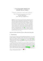
The basic concept of the ENVS is shown in Figure 2<br />
<strong>and</strong> is comprised of a stereo video camera headset<br />
fitted with a digital compass <strong>for</strong> obtaining video <strong>and</strong><br />
direction in<strong>for</strong>mation from the environment, a laptop<br />
computer equipped with a <strong>GPS</strong> unit <strong>for</strong> processing the<br />
video <strong>and</strong> direction data from the headset <strong>and</strong><br />
obtaining the <strong>GPS</strong> location of the user, a<br />
Transcutaneous Electro-Neural Stimulation (TENS)<br />
unit <strong>for</strong> converting the output from the computer into<br />
appropriate electrical pulses that can be felt via the<br />
skin, <strong>and</strong> special gloves fitted with electrodes <strong>for</strong><br />
delivering the electrical pulses to the fingers.
Figure 2. The basic concept of the ENVS<br />
3.1 Obtaining <strong>3D</strong> <strong>Perception</strong> from the<br />
ENVS<br />
The ENVS extracts depth in<strong>for</strong>mation from the<br />
environment by using the laptop computer to obtain a<br />
disparity depth map of the immediate environment<br />
from the head mounted stereo cameras. This is then<br />
converted into electrical pulses by the TENS unit that<br />
stimulates nerves in the skin via electrodes located in<br />
the TENS data gloves that can be seen in Figure 3. To<br />
achieve electrical conductivity between the electrodes<br />
<strong>and</strong> skin, a small amount of conductive gel is applied<br />
to the fingers prior to fitting the gloves. For our test<br />
purposes, the stereo camera headset is designed to<br />
completely block out the users eyes to simulate<br />
blindness.<br />
Figure 3. The ENVS setup<br />
The key to obtaining useful environmental<br />
in<strong>for</strong>mation from the electro-neural data gloves lies in<br />
representing the range data delivered to the fingers in<br />
an intuitive manner. To interpret this in<strong>for</strong>mation the<br />
user imagines his or her h<strong>and</strong>s are positioned in front<br />
of the abdomen with fingers extended. The amount of<br />
stimulation felt by each finger is directly proportional<br />
to the distance of objects in the direction pointed by<br />
each finger.<br />
To enable the stereo disparity algorithm parameters<br />
<strong>and</strong> the TENS output wave<strong>for</strong>m to be altered <strong>for</strong><br />
experimental purposes we provided the ENVS with<br />
the control panel shown in Figure 4. This was also<br />
designed to monitor the image data coming from the<br />
cameras <strong>and</strong> the signals being delivered to the fingers<br />
via the TENS unit.<br />
Figure 4 shows a typical screen grab of the ENVS’s<br />
control panel while in operation. The top-left image<br />
shows a typical environment image obtained from one<br />
of the cameras in the stereo camera headset. The<br />
corresponding disparity depth map, derived from both<br />
cameras, can be seen in the top-right image (i.e.<br />
lighter pixels have a closer range than darker pixels).<br />
Also, the ten disparity map sample regions, used to<br />
obtain the ten range readings delivered to the fingers,<br />
can be seen spread horizontally across the centre of<br />
the disparity map image. These regions are also<br />
adjustable via the control panel.<br />
Figure 4. The ENVS control panel.<br />
To calculate the amount of stimulation delivered to<br />
each finger, the minimum depth of each of the ten<br />
sample regions is taken. The bar graph, at the bottomleft<br />
of Figure 4, shows the actual amount of<br />
stimulation delivered to each finger. Using a 1000<br />
MHz Pentium computer we were able to achieve a<br />
frame rate of 15 frames per second which proved<br />
more than adequate <strong>for</strong> our experiments.<br />
3.1.1 Extracting Depth from Stereo Video<br />
The ENVS works by using the principle of stereo<br />
disparity [see [15]). Just as our eyes capture two<br />
slightly different images <strong>and</strong> our brain combines them<br />
with a sense of depth, the stereo cameras in the ENVS<br />
captures two images <strong>and</strong> the laptop computer<br />
computes a depth map by estimating the disparity<br />
between the two images. However, unlike binocular<br />
vision on humans <strong>and</strong> animals, which have<br />
independently moveable eye balls, typical stereo<br />
vision systems use parallel mounted video cameras<br />
positioned at a set distance from each other.<br />
3.1.2 Limitations<br />
To calculate the disparity between image pixels the<br />
stereo disparity algorithm requires features to be<br />
detected in the stereo images. Consequently,<br />
featureless surfaces can pose a problem <strong>for</strong> the<br />
disparity algorithm due to a lack of identifiable<br />
features. For example, Figure 5 illustrates this<br />
problem with a disparity map of a whiteboard. As the<br />
whiteboard surface has no identifiable features on it,
the disparity of this surface <strong>and</strong> its range cannot be<br />
calculated. To make the ENVS user aware of this, the<br />
ENVS maintains a slight signal if a region contains<br />
only distant features <strong>and</strong> no signal at all if the<br />
disparity cannot be calculated due to a lack of features<br />
in a region. With further work we expect to overcome<br />
this deficiency by also incorporating IR range sensors<br />
into the ENVS headset.<br />
Figure 5. Disparity map of a featureless surface<br />
3.2 Perceiving L<strong>and</strong>marks with the ENVS<br />
To enable l<strong>and</strong>marks to be perceived by blind users<br />
the ENVS is equipped with a <strong>GPS</strong> unit, a dig ital<br />
compass <strong>and</strong> a database of l<strong>and</strong>marks. The digital<br />
compass, shown in Figure 6, is mounted on the stereo<br />
camera headset <strong>and</strong> is used to determine if the user is<br />
looking in the direction of any l<strong>and</strong>marks.<br />
Figure 6. Digital compass mounted on headset<br />
L<strong>and</strong>marks can be loaded from a file or entered by the<br />
user by pressing a button on the ENVS <strong>and</strong> are<br />
associated with their <strong>GPS</strong> location <strong>and</strong> an ID number.<br />
L<strong>and</strong>marks are considered to be any significant object<br />
or feature in the environment that can enable the user<br />
to approximate his or her position from. They can also<br />
be a location the user wants to remember, e.g. a bus<br />
stop or a parking location of a vehicle. By using the<br />
<strong>GPS</strong> unit to obtain the user’s location the ENVS is<br />
able to maintain a list of direction vectors to<br />
l<strong>and</strong>marks that are within a set radius from the user.<br />
The l<strong>and</strong>mark radius can be set to short or long range<br />
(200-600m) by the user via a switch on the ENVS<br />
unit. When a l<strong>and</strong>mark is calculated to be within the<br />
user’s ENVS visual field, (as determined by the<br />
headset compass <strong>and</strong> the set l<strong>and</strong>mark radius), the<br />
perceived l<strong>and</strong>mark’s ID is encoded into a sequence<br />
of pulses <strong>and</strong> delivered to the user via the finger<br />
which represents the direction of the l<strong>and</strong>mark. For<br />
example, if a l<strong>and</strong>mark is determined to be in the far<br />
left visual field, the pulse sequence corresponding to<br />
the l<strong>and</strong>mark will be felt on the left pinky finger.<br />
To encode the l<strong>and</strong>mark’s ID a 5 bit sequence of dots<br />
<strong>and</strong> dashes carried by a 400Hz signal is used to<br />
represent binary numbers. To avoid interfering with<br />
the range readings of objects, which are also delivered<br />
to the fingers via the ENVS (see Section 3.1),<br />
locations are delivered to the fingers in 5 second<br />
intervals. Thus if a l<strong>and</strong>mark is detected, the user will<br />
receive range readings via the fingers <strong>for</strong> 4 seconds<br />
followed by approximately 1 second of l<strong>and</strong>mark ID<br />
in<strong>for</strong>mation. If more than one l<strong>and</strong>mark is present<br />
within the set l<strong>and</strong>mark radius <strong>and</strong> the visual field of<br />
view, the l<strong>and</strong>mark nearest to the center of the visual<br />
field will be output to the user.<br />
By using 5 bits to represent l<strong>and</strong>mark IDs, the ENVS<br />
is able to store up to 32 locations which proved<br />
adequate <strong>for</strong> our experiments. The distance to the<br />
l<strong>and</strong>mark is indicated by the intensity of the pulses.<br />
Weak sensations indicate that the l<strong>and</strong>mark is near to<br />
the set l<strong>and</strong>mark radius. Strong sensations indicate<br />
that the l<strong>and</strong>mark is only meters away from the user.<br />
If the user has difficulty recognizing l<strong>and</strong>marks by<br />
their pulse sequence a button is available on the<br />
ENVS unit to output the location, distance <strong>and</strong><br />
bearing of the perceived l<strong>and</strong>mark as speech.<br />
4 Experimental Results<br />
To test the ENVS we conducted a number of<br />
experiments within the campus grounds with different<br />
users to determine the extent to which the users could<br />
navigate the campus environment without any use of<br />
the eyes. All the ENVS users were familiar with the<br />
campus grounds <strong>and</strong> the l<strong>and</strong>marks stored in the<br />
ENVS <strong>and</strong> had no visual impairments. To simulate<br />
blindness with sighted users the stereo camera headset<br />
was designed to fit over the user’s eyes so that no<br />
light whatsoever could enter the eyes. All reported<br />
tests were conducted on users who had at least 1 hour<br />
practise at using the ENVS.<br />
4.1 Navigating the Car Park<br />
Our first test was done to determine if the ENVS<br />
users could navigate a car park <strong>and</strong> arrive at a target<br />
vehicle location that was encoded into the ENVS as a<br />
l<strong>and</strong>mark. Each user was fitted with the ENVS <strong>and</strong><br />
lead blindfolded to a location in the car-park that was<br />
unknown to them <strong>and</strong> asked to navigate to the target<br />
vehicle using only the ENVS electro-tactile signals.<br />
The car-park was occupied to approximately 75% of<br />
its full capacity <strong>and</strong> also contained some obstacles<br />
comprising green strips <strong>and</strong> lighting poles.
Generally we found all users were able to perceive<br />
<strong>and</strong> describe their surroundings <strong>and</strong> the location of the<br />
target vehicle in sufficient detail <strong>for</strong> them to be able to<br />
navigate to the target vehicle without bumping into<br />
cars or lighting posts. We found experienced users<br />
could also interpret the range data without any need to<br />
hold their h<strong>and</strong>s in front of the abdomen <strong>and</strong> could<br />
walk between closely spaced vehicles without<br />
colliding with the vehicles.<br />
Figure 7a shows a user observing two closely spaced<br />
vehicles in the car-park with the ENVS. The profile of<br />
the space between the vehicles can be seen in the<br />
disparity map, shown in the top right of Figure 7b,<br />
<strong>and</strong> in the finger pulse histogram shown at the lower<br />
left of Fig 7b. The yellow bar at the left <strong>for</strong>efinger<br />
position of the finger histogram, indicates that target<br />
vehicle is located slightly to the left of where the user<br />
is looking <strong>and</strong> at a distance of approximately 120m.<br />
(a)<br />
(b)<br />
Figure 7. (a) Photo of an ENVS user negotiating the<br />
car-park. (b) The ENVS screen dump showing the<br />
perceived vehicles <strong>and</strong> the target l<strong>and</strong>mark’s direction<br />
<strong>and</strong> distance.<br />
4.2 Navigating the Campus<br />
Experiments were also per<strong>for</strong>med within the campus<br />
to determine the potential of the EVNS to enable<br />
blindfolded users to navigate the campus without<br />
using other aids. The main test was to see if users<br />
could navigate between two locations some distance<br />
apart (~500m) <strong>and</strong> avoid any obstacles that might be<br />
in the way. All users who per<strong>for</strong>med this test were<br />
fami liar with the campus environment <strong>and</strong> had some<br />
experience at using the ENVS. The path was flat <strong>and</strong><br />
contained no stairs between the two locations. A<br />
number of familiar l<strong>and</strong>marks were stored in the<br />
ENVS in the vicinity of the two locations.<br />
We found that all users were able to avoid obstacles,<br />
report their approximate location <strong>and</strong> orientation <strong>and</strong><br />
arrive at the destination without difficulty. Unlike the<br />
car park, the path was comprised of pavers with many<br />
joins making it clearly visible to the disparity<br />
cameras. Consequently, this delivered clearly defined<br />
range readings of the paved path to the user via the<br />
ENVS unit as shown in Figure 8.<br />
(a)<br />
(b)<br />
Figure 8. (a) Photo of an ENVS user surveying a<br />
paved path in the campus environment. (b) The<br />
associated ENVS screen dump. The yellow bar in the<br />
range histogram indicates a l<strong>and</strong>mark being delivered<br />
to the user.<br />
This presented a minor problem <strong>for</strong> some<br />
inexperienced users as they were unable to determine<br />
where the path ended <strong>and</strong> the grass began in some
places using the ENVS range stimulus alone.<br />
However, this did not cause any collisions <strong>and</strong> the<br />
users became quickly aware of the edge of the path<br />
whenever their feet made contact with the grass. We<br />
hope to overcome this minor problem by encoding<br />
colour into the range signals delivered to the fingers<br />
by varying the frequency of the tactile signals.<br />
5 Conclusion<br />
This paper describes our preliminary experimental<br />
results in developing a substitute vision system <strong>for</strong> the<br />
blind capable of providing <strong>3D</strong> perception of the<br />
environment <strong>and</strong> l<strong>and</strong>mark identification via an<br />
electro-tactile interface. The main problem with<br />
existing substitute vision systems <strong>for</strong> the blind is that<br />
the in<strong>for</strong>mation delivered to the user is in a <strong>for</strong>m that<br />
is either hard <strong>for</strong> the user to underst<strong>and</strong> or difficult <strong>for</strong><br />
the brain to derive a <strong>3D</strong> model of the environment<br />
from. Also, existing substitute vision systems do not<br />
provide an adequate means <strong>for</strong> the user to perceive<br />
l<strong>and</strong>marks which are important <strong>for</strong> navigation.<br />
Although, commercial <strong>GPS</strong> units are available <strong>for</strong> the<br />
blind, they generally use an audio or voice interface<br />
which can interfere with a blind person’s ability to<br />
hear important environmental sounds. The sounds<br />
made by talking <strong>GPS</strong> units can also undesirably<br />
attract the attention of nearby individuals.<br />
Our outdoor experimental results demonstrate that our<br />
ENVS is able to provide a blindfolded user with the<br />
ability to avoid obstacles, navigate the environment<br />
<strong>and</strong> locate his or her position in the environment via<br />
familiar l<strong>and</strong>marks by interpreting sensory data via<br />
the electro-tactile data gloves.<br />
With further work we hope to develop the ENVS into<br />
an effective device capable of providing the blind<br />
with increased environment perception <strong>and</strong> autonomy.<br />
This additional work includes the incorporation of<br />
colour perception into the range signals delivered to<br />
the user via the electro-tactile interface, adding<br />
infrared range sensors into the headset <strong>for</strong> detecting<br />
the range of featureless surfaces, the development of<br />
compact hardware <strong>for</strong> reducing the bulkiness of the<br />
ENVS <strong>and</strong> the fabrication of alternative TENS<br />
interfaces eliminating the need <strong>for</strong> the user to where<br />
electro-tactile data gloves.<br />
6 Acknowledgements<br />
This work was undertaken with the assistance of an<br />
Australian Research Council Discovery Grant.<br />
7 References<br />
[1] World Health Organisation, Magnitude <strong>and</strong><br />
Causes of Visual Impairment, Fact Sheet<br />
No.282, November 2004.<br />
[2] Wyatt, J.L. <strong>and</strong> Rizzo, J.F., Ocular Implants <strong>for</strong><br />
the Blind, IEEE Spectrum, Vol.33, pp.47-53,<br />
May 1996.<br />
[3] Rizzo, J.F. <strong>and</strong> Wyatt, J.L., Prospects <strong>for</strong> a<br />
Visual Prosthesis, Neuroscientist, Vol.3, pp.251-<br />
262, July 1997.<br />
[4] Rizzo, J.F. <strong>and</strong> Wyatt, J.L., Retinal Prosthesis,<br />
in: Age-Related Macular Degeneration, J.W.<br />
Berger, S.L. Fine <strong>and</strong> M.G. Maguire, eds.,<br />
Mosby, St. Louis, pp. 413 - 432. 1998.<br />
[5] Dobelle, W. Artificial <strong>Vision</strong> <strong>for</strong> the Blind by<br />
Connecting a Television Camera to the Visual<br />
Cortex, American Society of Artificial Internal<br />
Organs Journal, January/February 2000.<br />
[6] Meijer, P.B.L. An Experimental <strong>System</strong> <strong>for</strong><br />
Auditory Image Representations, IEEE<br />
Transactions on Biomedical Engineering, Vol.<br />
39, No. 2, pp. 112-121, February 1992.<br />
[7] Kay, L. Auditory <strong>Perception</strong> of Objects by Blind<br />
Persons Using Bioacoustic High Resolution Air<br />
Sonar. JASA, Vol 107, pp 3266-3275, No 6, June<br />
2000.<br />
[8] Kaczmarek, K.A. <strong>and</strong> Bach-y-Rita, P., Tactile<br />
Displays, in Virtual Environments <strong>and</strong> Advanced<br />
Interface Design, Barfield, W. <strong>and</strong> Furness, T.,<br />
Eds. New York: Ox<strong>for</strong>k University Press, pp.<br />
349-414, 1995.<br />
[9] Helal, A.; Moore, S.E.; Ramach<strong>and</strong>ran, B.,<br />
Drishti: an integrated navigation system <strong>for</strong><br />
visually impaired <strong>and</strong> disabled, Proceedings,<br />
Fifth International Symposium on Wearable<br />
Computers, 2001.<br />
[10] Mosen, J.; What's New with Pulse Data<br />
International's Braillenote PDA <strong>for</strong> the Blind,<br />
Center on Disabilities Technology <strong>and</strong> Persons<br />
with Disabilities Conference, 2005.<br />
[11] Daviault, J.; Study On The Benefits Of <strong>GPS</strong>-<br />
Based Orientation Tools <strong>for</strong> the Mobility <strong>and</strong><br />
Orientation of the Blind, Center on Disabilities<br />
Technology <strong>and</strong> Persons with Disabilities<br />
Conference, 2005.<br />
[12] Balach<strong>and</strong>ran, W.; Cecelja, F.; Ptasinski, P., A<br />
<strong>GPS</strong> based navigation aid <strong>for</strong> the blind, ICECom,<br />
2003<br />
[13] Virkes, D.; Nenadic, K.; Virkes, D.Z.,<br />
Positioning systems <strong>for</strong> mobility of the blind,<br />
overview <strong>and</strong> analysis, Proceedings, 46th<br />
International Symposium Electronics in Marine<br />
(ELMAR), 2004.<br />
[14] S. Meers <strong>and</strong> K. Ward, A <strong>Vision</strong> <strong>System</strong> <strong>for</strong><br />
<strong>Providing</strong> <strong>3D</strong> <strong>Perception</strong> of the Environment via<br />
Transcutaneous Electro-Neural Stimulation.<br />
Proceedings of the 8th IEEE International<br />
Conference on In<strong>for</strong>mation Visualisation,<br />
London, pages 546-552, July 2004.<br />
[15] Banks, J. Bennamoun, M. <strong>and</strong> Corke, P., Non-<br />
Parametric Techniques <strong>for</strong> Fast <strong>and</strong> Robust<br />
Stereo Matching, Proceedings of the IEEE<br />
TENCON'97, Brisbane, December 1997.