Effect of Polyimide Variation and its Curing Temperature on CMOS ...
Effect of Polyimide Variation and its Curing Temperature on CMOS ...
Effect of Polyimide Variation and its Curing Temperature on CMOS ...

You also want an ePaper? Increase the reach of your titles
YUMPU automatically turns print PDFs into web optimized ePapers that Google loves.
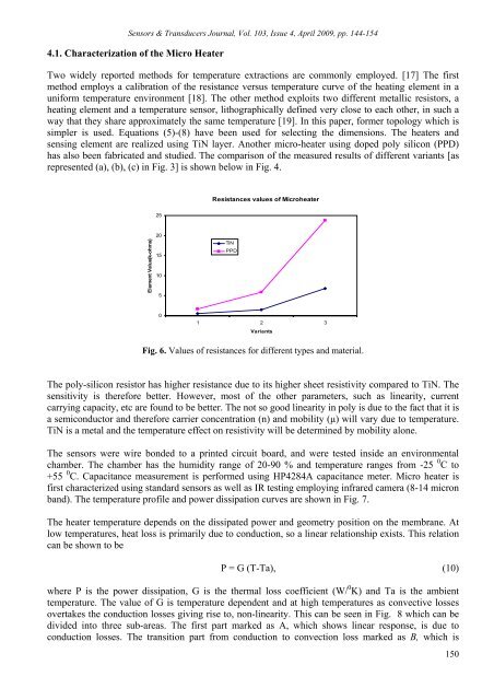
Sensors & Transducers Journal, Vol. 103, Issue 4, April 2009, pp. 144-1544.1. Characterizati<strong>on</strong> <str<strong>on</strong>g>of</str<strong>on</strong>g> the Micro HeaterTwo widely reported methods for temperature extracti<strong>on</strong>s are comm<strong>on</strong>ly employed. [17] The firstmethod employs a calibrati<strong>on</strong> <str<strong>on</strong>g>of</str<strong>on</strong>g> the resistance versus temperature curve <str<strong>on</strong>g>of</str<strong>on</strong>g> the heating element in auniform temperature envir<strong>on</strong>ment [18]. The other method explo<str<strong>on</strong>g>its</str<strong>on</strong>g> two different metallic resistors, aheating element <str<strong>on</strong>g>and</str<strong>on</strong>g> a temperature sensor, lithographically defined very close to each other, in such away that they share approximately the same temperature [19]. In this paper, former topology which issimpler is used. Equati<strong>on</strong>s (5)-(8) have been used for selecting the dimensi<strong>on</strong>s. The heaters <str<strong>on</strong>g>and</str<strong>on</strong>g>sensing element are realized using TiN layer. Another micro-heater using doped poly silic<strong>on</strong> (PPD)has also been fabricated <str<strong>on</strong>g>and</str<strong>on</strong>g> studied. The comparis<strong>on</strong> <str<strong>on</strong>g>of</str<strong>on</strong>g> the measured results <str<strong>on</strong>g>of</str<strong>on</strong>g> different variants [asrepresented (a), (b), (c) in Fig. 3] is shown below in Fig. 4.Resistances values <str<strong>on</strong>g>of</str<strong>on</strong>g> Microheater25Element Value(k-ohms)2015105TiNPPD01 2 3VariantsFig. 6. Values <str<strong>on</strong>g>of</str<strong>on</strong>g> resistances for different types <str<strong>on</strong>g>and</str<strong>on</strong>g> material.The poly-silic<strong>on</strong> resistor has higher resistance due to <str<strong>on</strong>g>its</str<strong>on</strong>g> higher sheet resistivity compared to TiN. Thesensitivity is therefore better. However, most <str<strong>on</strong>g>of</str<strong>on</strong>g> the other parameters, such as linearity, currentcarrying capacity, etc are found to be better. The not so good linearity in poly is due to the fact that it isa semic<strong>on</strong>ductor <str<strong>on</strong>g>and</str<strong>on</strong>g> therefore carrier c<strong>on</strong>centrati<strong>on</strong> (n) <str<strong>on</strong>g>and</str<strong>on</strong>g> mobility (µ) will vary due to temperature.TiN is a metal <str<strong>on</strong>g>and</str<strong>on</strong>g> the temperature effect <strong>on</strong> resistivity will be determined by mobility al<strong>on</strong>e.The sensors were wire b<strong>on</strong>ded to a printed circuit board, <str<strong>on</strong>g>and</str<strong>on</strong>g> were tested inside an envir<strong>on</strong>mentalchamber. The chamber has the humidity range <str<strong>on</strong>g>of</str<strong>on</strong>g> 20-90 % <str<strong>on</strong>g>and</str<strong>on</strong>g> temperature ranges from -25 0 C to+55 0 C. Capacitance measurement is performed using HP4284A capacitance meter. Micro heater isfirst characterized using st<str<strong>on</strong>g>and</str<strong>on</strong>g>ard sensors as well as IR testing employing infrared camera (8-14 micr<strong>on</strong>b<str<strong>on</strong>g>and</str<strong>on</strong>g>). The temperature pr<str<strong>on</strong>g>of</str<strong>on</strong>g>ile <str<strong>on</strong>g>and</str<strong>on</strong>g> power dissipati<strong>on</strong> curves are shown in Fig. 7.The heater temperature depends <strong>on</strong> the dissipated power <str<strong>on</strong>g>and</str<strong>on</strong>g> geometry positi<strong>on</strong> <strong>on</strong> the membrane. Atlow temperatures, heat loss is primarily due to c<strong>on</strong>ducti<strong>on</strong>, so a linear relati<strong>on</strong>ship exists. This relati<strong>on</strong>can be shown to beP = G (T-Ta), (10)where P is the power dissipati<strong>on</strong>, G is the thermal loss coefficient (W/ 0 K) <str<strong>on</strong>g>and</str<strong>on</strong>g> Ta is the ambienttemperature. The value <str<strong>on</strong>g>of</str<strong>on</strong>g> G is temperature dependent <str<strong>on</strong>g>and</str<strong>on</strong>g> at high temperatures as c<strong>on</strong>vective lossesovertakes the c<strong>on</strong>ducti<strong>on</strong> losses giving rise to, n<strong>on</strong>-linearity. This can be seen in Fig. 8 which can bedivided into three sub-areas. The first part marked as A, which shows linear resp<strong>on</strong>se, is due toc<strong>on</strong>ducti<strong>on</strong> losses. The transiti<strong>on</strong> part from c<strong>on</strong>ducti<strong>on</strong> to c<strong>on</strong>vecti<strong>on</strong> loss marked as B, which is150