NGC-UIT-ORD to NGC-UIT2-ORD - Pentair
NGC-UIT-ORD to NGC-UIT2-ORD - Pentair
NGC-UIT-ORD to NGC-UIT2-ORD - Pentair

Create successful ePaper yourself
Turn your PDF publications into a flip-book with our unique Google optimized e-Paper software.
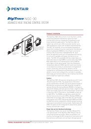
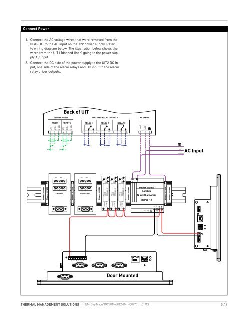
Connect Power1. Connect the AC voltage wires that were removed from the<strong>NGC</strong>-<strong>UIT</strong> <strong>to</strong> the AC input on the 12V power supply. Refer<strong>to</strong> wiring diagram below. The illustration below shows thewires from the <strong>UIT</strong>1 (dashed lines) going <strong>to</strong> the power supplyAC input.2. Connect the DC side of the power supply <strong>to</strong> the <strong>UIT</strong>2 DC input,one side of the alarm relays and DC input <strong>to</strong> the alarmrelay driver outputs.Back of <strong>UIT</strong>RS-485 PORTSFAIL SAFE RELAY OUTPUTSAC INPUTFIELD REMOTESIG–SIG+SHLDSIG–SIG+SHLD1 2 3 4 5 6WH BK S SWH BKRELAY 1 RELAY 2 RELAY 31 2 3 4 5 6 7 8 9 10 11Line/L1N/L21 2 3N\L2Line\L1AC InputBKWHBKWH1212125432 15432 1111411141114LNPhoenix 0800886Phoenix 3031238SH 9 8 7 6Field PortPhoenix 3031238SH 9 8 7 6Remote PortPhoenix 0800886RelaySPDTRTB14012FRelaySPDTRTB14012FRelaySPDTRTB14012FPhoenix 0800886Power SupplyLambda12 Vdc @ 4.5 AmpsDSP60-12Phoenix 3031238Phoenix 0800886SocketA2RT78724A1SocketA2RT78724A1SocketA2RT78724A1–– + +Vout Adj.+8 7 6 5 4 3 2 1–Door MountedTHERMAL MANAGEMENT SOLUTIONS EN-DigiTrace<strong>NGC</strong><strong>UIT</strong><strong>to</strong><strong>UIT</strong>2-IM-H58770 01/135 / 8