TMdrive -70 Product Application Guide - Tmeic.com
TMdrive -70 Product Application Guide - Tmeic.com
TMdrive -70 Product Application Guide - Tmeic.com

You also want an ePaper? Increase the reach of your titles
YUMPU automatically turns print PDFs into web optimized ePapers that Google loves.
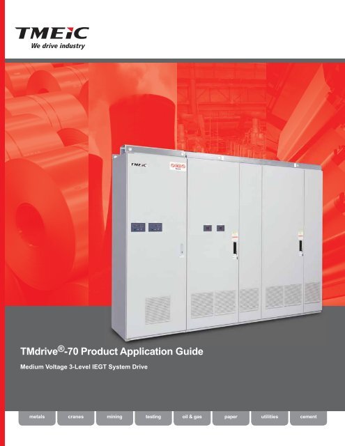
<strong>TMdrive</strong> ® -<strong>70</strong> <strong>Product</strong> <strong>Application</strong> <strong>Guide</strong>Medium Voltage 3-Level IEGT System Drivemetalscranesminingtestingoil & gaspaperutilitiescement
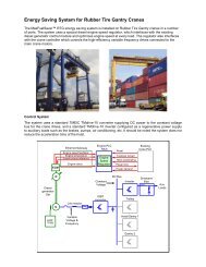
ACACACACACACACACLocal Monitoring/Control/AnalysisThe family of <strong>TMdrive</strong> ® ac systemdrives is targeting specificcustomer requirements for:EthernetMELPLACControllersInnovation Series Controller (ISC)VVseries ControllerV Series Controller• High reliability• Simple configuration and maintenance• Low cost of ownershipMELPLAC Net<strong>TMdrive</strong>MELVECISBusDLAN+Profibus-DP<strong>TMdrive</strong>TOSVERTTOSLINE-S20Series Six Parallel I/O BusGenius ®FieldControl I/OGenius ® I/OBlockVersaMax ®TOSLINE-S20V<strong>TMdrive</strong>LEOPACKVseries I/OV Series I/OTOSVERTInstalled I/Oand DrivesLEOPACKLV• Series Six I/O• DIRECTO-MATIC ® Plus I/O• DIRECTO-MATIC Controller• Digital Siltron DrivesMVLegacy Drive <strong>Product</strong>sDC2000IEGT Technology Dramatically Lowers Cost of OwnershipThe Injection Enhanced Gate Transistor (IEGT) is a breakthrough in power switchtechnology. The following set of features and associated benefits details how thisdevice lowers your cost of ownership versus previous main drive technology.Features• Low Voltage Gate DriveGiven that the IEGT is a MOSstructure, it can be gated(turned on/off) with ±15 V.• Minimal Snubber CircuitryWith the high dV/dt capability ofthe IEGT, there is only need for asmall dc clamp snubber circuit.• High-Speed SwitchingThe IEGT is switched at a rate of500 Hz in this application.Benefits• High Efficiency and Small SizeA very <strong>com</strong>pact phase leg assembly is achieved with:• A reduction in snubber circuitry• Integral forward diodes• Integral clamp diodes• Higher PerformanceThe reduction in snubber circuitry allows a higherchopping frequency, lowering the torque rippleapplied to the motor and harmonics fed back intothe power system.• Motor and Power System FriendlyThe high-speed switching coupled with the threelevelpower bridge design delivers a smooth sinewave to the motor and power system.2
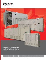
A Look InsideState-of-the-Art Technology:• Injection Enhanced GateTransistor (IEGT)-basedconverter and inverterprovides power to the processat near unity power factor withminimum harmonic distortion• Water-cooling technologyfor the power bridge reduces thefootprint of the equipment savingvaluable space in your factory• Modular design for powerbridge minimizes the timerequired for any maintenanceactivitiesControl CabinetConverter Front ViewControl FunctionsEach inverterand regenerativeconverter shares a<strong>com</strong>mon setof control boards. The primarycontrol board performs severalfunctions:• Speed and torque regulation• Sequencing• I/O mapping• Diagnostic data gatheringA mounting bracket is provided foran optional LAN interface board.I/O BoardThe I/O boardsupports encoder orresolver, 24 V dc I/O,115 V ac inputs and analog I/O,standard. All I/O are terminatedto a two-piece modular terminalblock for ease of maintenance.IEGT Three-Level Phase Leg AssemblyThe drive has a total of six identical Injection Enhanced GateTransistor (IEGT) phase leg assemblies in the converter and inverter.The modular draw-out assembly includes:• Four IEGT power semiconductors with integrated flyback diodes• Neutral-point clamp diodes• Water-cooled piping assembly with quick disconnect fittings• IEGT gate driver circuit board• Feedback control circuitry• dc clamp snubber mounted on top4
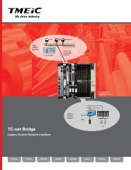
Inverter Front ViewOptional Remote ControlModular construction allowsthe power converter andcontrol cabinets to be installedup to 150 m (500 ft) apart.This optimizes the use of space in yourequipment room.dc BusThe converter generates dc power forNPthe inverter. The inverter then createsvariable frequency ac power tocontrol the induction or synchronousmotor. The dc power between the converterand inverter is conveyed on a solid copperbus behind the phase leg assemblies in bothcabinets. For <strong>com</strong>mon bus systems this bus isextended to adjacent cases.Inverter Back ViewConverter Back ViewOutputVoltageOutputCurrentMain CapacitorsOil filled dc capacitorsare used to providelong life under allservice conditions andduty cycles.Main Power3-Phase motor andtransformer are made inthe rear. Both top andbottom e supported.Cooling Water Interface150 mm JIS-10K50A fittings areprovided for connecting cooling waterfor de-ionized cooling loop. Waterinterface shown here is for “separate”type water conditioner.5
<strong>TMdrive</strong>-Flexible Topologies To Match Your Needs<strong>TMdrive</strong>–<strong>70</strong> IEGT Inverter8000 Frame10000 FrameConfiguration Options1 Bank Converter1 Bank InverterHigh SpeedFusesDischargeResistors2430 V dcMotor CurrentSensor<strong>TMdrive</strong>-P<strong>70</strong>2430 V dc4 Bank Converter4 Bank Inverter<strong>TMdrive</strong>–P<strong>70</strong> Regenerative IEGT Converter8000 Frame10000 Frame<strong>TMdrive</strong>-P<strong>70</strong>+CircuitBreaker3550 V ac2430 V dcNP<strong>TMdrive</strong>-2430 V dcControl-<strong>TMdrive</strong>-P<strong>70</strong>380/440/460 V acInitial ChargingCircuitSystemGround6
1 Bank Converter2x1 Bank InverterMM<strong>TMdrive</strong>-<strong>70</strong><strong>TMdrive</strong>-P<strong>70</strong><strong>TMdrive</strong>-<strong>70</strong>M<strong>TMdrive</strong>-<strong>70</strong>2 Bank Converter2 Bank Inverter<strong>TMdrive</strong>-D/P<strong>70</strong>-P<strong>70</strong><strong>TMdrive</strong>-<strong>70</strong>M<strong>TMdrive</strong>-<strong>70</strong><strong>TMdrive</strong>-P<strong>70</strong><strong>TMdrive</strong>-<strong>70</strong><strong>TMdrive</strong>-<strong>70</strong>M2 Bank Converter3x1 Bank Inverter-P<strong>70</strong><strong>TMdrive</strong>-<strong>70</strong>M<strong>TMdrive</strong>-P<strong>70</strong><strong>TMdrive</strong>-<strong>70</strong>M<strong>TMdrive</strong>-<strong>70</strong><strong>TMdrive</strong>-<strong>70</strong><strong>TMdrive</strong>-P<strong>70</strong>M<strong>TMdrive</strong>-<strong>70</strong>7
Regenerative SystemsACThree-Level Phase Leg Assembly for Both Converter and InverterHigh SpeedFusesQuick disconnectfittings for thecooling systemreduces meantime to repairDischargeResistors2430 V dc2430 V dcMotor CurrentSensorCompact gatedriver assembliesdue to lowpower switchingrequirements ofthe IEGT devices2375 mm (94 in)2375 mm (94 in)2375 mm (94 in)2375 mm (94 in)8Control Cabinet Depth: <strong>70</strong>0 mm (28 in)IEGT devices with integral forward andclamp diodes allow a very <strong>com</strong>pact phaseleg stack, reducing the footprint versusprevious technologyWidth: 3200 mm (126 in) Depth: 1650 mm (65 in)Control Cabinet Depth: <strong>70</strong>0 mm (28 in)Width: 5600 mm (220 in) Depth: 1650 mm (65 in)Control Cabinet Depth: <strong>70</strong>0 mm (28 in)Width: 6400 mm (252 in) Depth: 1650 mm (65 in)Width: 4800 mm(189 in)Depth: 1650 mm(65 in)dc clamp snubber circuit used to absorb theenergy generated in turning off the IEGTsBanks124Frame8000Weightkg (lbs)4900(10780)10000 5200(11440)16000 9500(20900)20000 10200(224400)32000 19000(41800)40000 20300(44660)ControlPowerkVA3.83.87.27.214.314.3MotorCurrentA acAllowableOverload%1360 1501166 1751020 200907 225816 2501<strong>70</strong>0 1501457 1751275 2001133 2251020 2502720 1502331 1752040 2001813 2251632 2503400 1502914 1752550 2002267 2252040 2505440 1504663 1754080 2003627 2253264 2506800 1505829 1755100 2004533 2254080 250
ACEnvironmental (Inverters and Converters)Mechanical (Inverters and Converters)Operating AirTemperatureStorage TemperatureHumidityAltitudeVibrationOperating WaterTemperature0 to 40°C (32 to 104°F) at rated load0 to 50°C (32 to 122°F) with derating-20 to 55°C (-13 to 131°F)5 to 95% relative humidityNon-condensing0 to 1000 m above sea level10-50 Hz,
Water Conditioning EquipmentPower BridgePower Converter PanelPower BridgePower ConverterPanel(s)Water conditioning control panelcontinuously monitors the status ofthe water system. Separate faultindications help find and fixproblems fast.WaterPanelIntegrated water system has internalplumbing for de-ionized cooling loop.WaterPanelSeparate type cooling has field-installedplumbing for de-ionized cooling loop.Water to water heatexchanger keeps thede-ionized systemisolated from the plantwater supply.Surge tank absorbswater during pumptransients andindicates the internalcooling loop waterlevel.De-ionizer removescontaminants for theinternal cooling loop.Redundant pumpskeep the systemrunning even if onepump failsTypeCapacityWidthmm (in)Depthmm (in)Heightmm (in)Weightkg (lbs)kVANotesIntegrated withLineup125 kW1200(48)1650(65)2375(94)1600(3527)5Capacity for one converter/inverter, (1 bank)Plant water required: 300 l/min (80 gal/min)SeparateCabinet250 kW1200(48)2000(79)2500(99)1650(3638)10Capacity for two converters/inverters, (2 bank)Plant water required: 600 l/min (160 gal/min)SeparateCabinet500 kW 3000(118)2000(79)2500(99)2650(5842) 15Plant water required: 1200 l/min (4 bank)(320 gal/min)SeparateCabinet750 kW 4300(1<strong>70</strong>)2000(79)2500(99)4300(9480) 25Plant water required: 1800 l/min (6 bank)(475 gal/min)Advanced PWM TechnologyAdvanced PWM control brings enhanced efficiency and reduced harmonics to <strong>TMdrive</strong>-<strong>70</strong> systems. Fixed pulse patterngate control uses optimum gating sequences to almost eliminate switching losses in the IEGT device. Gating sequences arepre-<strong>com</strong>puted for the control rather than <strong>com</strong>puted at runtime. The result is performance that reduces losses and harmonics.Input CurrentDiode CurrentIEGT CurrentOutput Voltage10Conventional PWMFixed Pulse Pattern Control
Field Supply Specifications2375 mm (94 in)800 mm (32 in)Depth: 950 mm (37 in)2375 mm (94 in)Type1200 A2100 A1200 mm (47 in)Depth: 950 mm (37 in)OverloadTime(sec)Frame12002100Weightkg (lbs)300(660)<strong>70</strong>0(1540)ControlPowerKVAField Exciter Continuous Current Rating, dc Amps50 HZ 60 HZAC Leg Fusesprotect powerbridge fromfaults on theac lineAutonomousCrowbarpreventsdangerousmotorvoltages fromdevelopingunder certainfault conditions150% 175% 200% 225% 250% 300% 150% 175% 200% 225% 250% 300%10 1320 1200 1100 1010 940 810 1360 1240 1130 1040 960 83030 1230 1100 1000 900 820 710 1280 1130 1020 915 845 72060 1180 1040 920 830 760 645 1205 1060 945 850 775 660120 1120 980 860 760 690 585 1160 1000 885 790 710 59010 2376 2160 1980 1818 1692 1458 2448 2232 2034 1872 1728 149430 2214 1980 1800 1620 1476 1278 2304 2034 1836 1647 1521 129660 2124 1872 1656 1494 1368 1161 2169 1908 1<strong>70</strong>1 1530 1395 1188120 2016 1764 1548 1368 1242 1053 2088 1800 1593 1422 1278 10620.50.5VoltageVac(Vdc)500(675)500(675)2100 Frame Field SupplyDC FieldConnection BusMain Powermodule. Onemodule isapplied forthe 1200Asupply andtwo modulesfor the 2100Amodel.Ground Faultdetectionmoduleprovidesindicationof insulationfailureAC Connection Bus. ACvoltages up to 500 Vac canbe connected dependingonrequired voltageEnhanced Converter Technology<strong>TMdrive</strong>-P<strong>70</strong> VAR ControlThe <strong>TMdrive</strong>-P<strong>70</strong> converter can be configured in two modes, providingVAR Control within the limits of its current capacity.One mode is the conventional PWM type normally set to holdunity power factor for all load conditions. (Shown in red)Another mode is the Fixed Pattern type, providing voltage stability,improved harmonics and efficiency. The Fixed Pattern mode stabilizesline voltage by providing system VARs when line voltage is low anddrawing VARs from the system when the voltage is high. By convention,VARs from the system are (+) and cause the line voltage to drop whileVARs from the converter are (-) and cause the line voltage to rise. Therelationship of line voltage, loads MW and converter MVAR is shown bythe blue voltage lines depending on the measured line voltage.MVA vs. MW and Voltage11
<strong>Application</strong> ExamplesApplying the <strong>TMdrive</strong>-<strong>70</strong> Starts With the Motor DesignConsideration must be given to motor design when applying the <strong>TMdrive</strong>-<strong>70</strong>. A primary constraint is the motor terminal voltage. It isimportant that the motor terminal voltage does not exceed 3400Vac under any operating condition. Reserving voltage margin correctlyis critical to success. Detailed motor design data is needed for correct application.OL_VOverload derate. The rated motor voltage over theterminal voltage of the motor at maximum appliedoverload. Motors with no overload use 1.0.ST_VField forcing margin needed when applyingsynchronous motors. Apply 0.94 for synchronous motorsystems.RP_VReduction in maximum voltage due to the dc bus rippleof the drive at low frequencies. If the base frequency isbelow 5 Hz then this derate is 0.97, otherwise it is 1.0.SP_VSpeed margin. For motors that run above base speedthis is the ratio of the terminal voltage at base speedover the terminal voltage at top speed under maximumoverload at each point. Other motors use 1.0.Maximum Rated Motor Voltage = 3400 x OL_V x RP_V x ST_V x SP_VExperience has shown that the following maximum rated motor voltages apply based on the type of motorand the application.InductionSynchronousRated MotorOverloadExample(Maximum Voltage at max OLMaximum Rated Motor Volts FrequencyRequirement<strong>Application</strong>and top speed)3400 3300 60 Hz 100% Pump or Fan3300 3200 30 Hz 200% Mine Hoist3200 3100 5 Hz 225% Mill Stand<strong>TMdrive</strong>-<strong>70</strong> Notes1. Power bridge cabinets are 1650 mm (65in) in depth.Control cabinets are <strong>70</strong>0 mm (28 in) in depth. Dimensionsdo not include required 50 mm (2 in) channel base.2. Allocate a minimum of 550 mm (20 in) above cabinet forfan maintenance.3. Power rating data assumes ambient temperature of0-40 ˚C (32-104 ˚F), altitude up to 1000 m (3280 ft) abovesea level.4. The specified current ratings are continuous to which theindicated overload may be applied for a maximum of 60seconds.5. Each cabinet requires 3-phase control power.6. For high performance torque regulation, a temperaturesensor is mounted in the motor.7. All <strong>TMdrive</strong>-<strong>70</strong> cabinets require 1000 mm (40 in) backaccess for connections and maintenance.8. Speed and current regulator responses are <strong>com</strong>putedper the adjacent figure in radians/s. Speed regulatorresponses shown are maximum available. Actual responsewill be limited by drive train mechanical conditions.Accuracy and linearity specifications shown are asmeasured under controlled conditions in our lab and whiletypical may not be achievable in all systems.129. Water connections for separatetype cooling systems are locatednear the floor in the rear of powerconverter cabinets. The flange is1500 mm JIS-10K50A. Stainlesspiping is required for plumbing ofthe de-ionized loop.10. dc Bus bar included in lineups israted for one inverter only. For<strong>com</strong>mon bus systems, convertersStep ResponseResponse at 95%of final valueand inverters are arranged so that this limitationis not exceeded.11. When output or input reactors are used to parallel systemsthen the dc Buses of those systems must be connectedtogether.12. Systems that share a <strong>com</strong>mon dc Bus must have thesame winding configuration for their converter transformersecondaries.13. Field supply enclosures are typically installed directlybehind control enclosures within the lineup.14. <strong>TMdrive</strong>-D<strong>70</strong> converters require a minimum of 10% totalinput impedance. <strong>TMdrive</strong>-P<strong>70</strong> converters require aminimum of 15% total input impedance.15. Systems with a base frequency below 5 Hz mayrequire additional 800 mm (32 in) capacitor panelsfor each dc link.1T 95%includesresponse latencyTimeT 95%Response = 3/T95% (radians/s)
Inverter ExampleWhen specifying an inverter, start from the process requirements and work through the motor to the inverter.The following example illustrates this process.1Define processrequirements.2Select motor based on processrequirements and <strong>com</strong>puterequired inverter kVA.• 6500 kW (8<strong>70</strong>0 hp)• 500 rpm, 3100 V• Efficiency = 0.965• Power factor = 1.00• Service factor = 1.0• Synchronous3Compute continuouscurrent requirements forthe inverter based onthe selected motor.4Select inverter based oncontinuous current andoverload requirements.Scan the 150% entries in theinverter tables for a frame wherethe continuous current ratingexceeds 1234 amps.The 8000 frame meets thiscriterion (1360 amps) and isappropriate for this application.kW Shaft = 6500 kW (8<strong>70</strong>0 hp)500 rpmThe motor delivers constant torque fromzero to base speed of 500 rpm and 6500kW (8<strong>70</strong>0 hp).Duty cycle requires 150% for 10 sec. but hasrms duty cycle of 6500 kW (8<strong>70</strong>0 hp).I ac Inverter =kW Shaft x 1000 x SF Mtr3 x V Motor rated voltage x Eff Mtr x PF Mtr= 6500 x 1000 x 1.03 x 3150 V x 0.965 x 1.0= 1234 ampsCurrentA ac136011661020907816AllowableOverload %150175200225250Regenerative Converter (<strong>TMdrive</strong>-<strong>70</strong>) ExampleWhen specifying a converter, start from the process requirements and work through the motor to the inverter, and then theassociated converter. The following example illustrates this process (continuation of inverter application example from above):1 Compute kW requirementsinto the inverter. It isassumed that the converteris dedicated to the inverterspecified in the applicationexample above.It is also assumed that theconverter is controlled to unitypower factor.kW ac2I ac ConverterCompute continuous ac currentrequirement of the converter based on itspower requirements.3kW= ac x 10003 x V Converter line-to-line voltage x Eff drive= 6736 kW x 10003 x 3550 V x 0.985= 1112 amps= kW ShaftEff MtrNote: For sizing systems with peak powers in regenerative mode, adifferent equation is used to <strong>com</strong>pute power requirements.= 6500 kW0.965kW ac = kW Shaft x Eff Mtr= 6736 kWScan the regenerativeconverter table forentries that exceedyour overload (150%), time (60sec) and continuous currentrequirements (1112 amps). In thiscase the 8000 frame <strong>TMdrive</strong>-P<strong>70</strong>meets the requirement and isappropriate for this application.CurrentA ac136011661020907816Overload –Time150% – 60s175% – 60s200% – 60s225% – 60s250% – 60s13
A Common Control ToReduce Cost Of Ownership14Feedback AndStatusSpeedReferenceSpeedFeedbackConfigurationMeter OutputsDigital InputsDigital OutputsAnalog InputsAnalog OutputsSpeed FeedbackResolver Input(Induction Motor Only)Speed FeedbackEncoder InputSpeed TachFollower OutputMotorTemperatureFeedbackControl FunctionsI/O Mapping Capture Buffer SequencingSpeed/TorqueInstrumentation InterfaceD/A+24 V dc24-110 V dc48-120 V ac10 V, 4-20 mAD/A+12-24 V+ - 10 VI/O InterfaceM+50 V dcSinCosSinCosAB10 VA/DFdbk ExcitnABZSupply ExcitnMotor ControlPWM• RJ-45 Ethernet interface• 10 Mbps maximum• Drive Navigator option ofTOSLINE -S20 to Ethernetconnection using V-Seriescontroller as gateway• Toolbox option of ISBus toEthernet using Innovation Series controller as gateway• Motor current A and B, ±10 V• Quantity 5 configurable, ±10 V,8-bit resolution• Opto-coupled 20 mA• Quantity 6 configurable mapping• Opto-coupled 10 mA• Quantity 1 configurable mapping• Quantity 1 dedicated mapping• Open collector <strong>70</strong> mA• Quantity 6 user defined• Quantity 2 ±10 V or 4-20 mA- Differential 8 Ω inputimpedance- 12-bit resolution• Optional Quantity 2 ±10 V- 12 bit resolution(Optional forInverters only)• Quantity 4 ±10 V, 10 mA max• User defined• 12-bit resolution• Excitation frequency of 1 or 4 kHz• Source for resolvers is Tamagawa:www.tamagawa-seiki.co.jp• A quad B with marker• Maximum frequency of 100 kHz• Differential 5 or 15 V dc• 5 or 15 V dc at 200 mA supply• Maximum frequency of 10 kHz• External 15-24 V dc at100 mA max• High-resolution torque motortemperature feedback• 100 Ω positive temperature coefficientRTD or other sensor using optionalsignal conditioning moduleLAN Interface OptionsTOSLINE-S20• Supports run-time control (6 words in and 10 wordsout) from an Innovation Series controller or V Seriescontroller• Drives can directly exchange data betweenthemselves (4 words)• Fiber-optic bus in a star configuration• 2 Mbps peer-to-peer protocol; bus scan time based onthe number of nodes:Quantity of Nodes Bus Scan Time2-3 1 ms4-5 2 ms6-8 4 ms9-64 25 msISBus• Supports both run-time control (10 words in and 10words out) and Toolbox configuration/monitoring usingthe Innovation Series controller as a gateway betweenthe ISBus and Ethernet• RS-485 or optional fiber-optic bus in a synchronousring configuration• 5 Mbps master/follower (drive is the follower) protocolusing copper or fiber; bus scan time based on thenumber of nodes:Quantity of Nodes Bus Scan Time2-4 1 ms5-8 2 ms6 -16 4 ms17-32 8 msModbus• Supports run-time control (fixed 10 words in/out) froma Modbus-RTU controller• RS-485 copper bus• 1.2 kbps to 57.6 kbps master/follower protocol;update rates up to 20 ms/node possible at thehighest baud rate• Number of notes: 127 max per LANProfibus-DP • Supports run-time control (6 words in and out) from aProfibus-DP master controller• Copper bus in a daisy-chain configuration• 9.6 kbps to 12 Mbps master/follower protocol; busscan time based on the number of nodesDeviceNet • Supports run-time control (4 words in and 10 wordsout) from a DeviceNet master controller• Copper bus in a daisy-chain configuration• 125 kbps to 500 kbps master/follower protocol; busscan time based on the number of nodesNote: 1 word = 16 bits
Operator InterfacesStandard Display (Inverters and Regenerative Converters)Three-digit display alternates between speed and current whilerunning, or a fault code when there is an error.Three LEDs give a quickindication of the statusof the unitOptional analog meters can besupplied in addition to either thestandard or enhanced display. Upto four meters can be provided.LED IndicationReady On when the unitis ready to runRunningOn when the unitis runningRJ-45 Ethernet portis used for localtoolbox connectionInterlock buttondisables the driveAlarm/FaultBlinking LED indicatesalarm condition, whilesolid LED indicatesa faultKeypad Option (Inverters and Regenerative Converters)High FunctionDisplay• LCD backlight givesgreat visibility andlong life• Bar graphs, icons,menus, and digitalvalues <strong>com</strong>bineto provide concisestatus information,often eliminating theneed for traditionalanalog metersRJ-45 Ethernetport is used for the localtoolbox connectionEasy-to-understandnavigation buttonsallow quick accessto informationwithout resorting to aPC-based toolSwitch to local modeand operate theequipment rightfrom the keypadInstrumentation Interface• Two analog outputs are dedicated tomotor current feedback• Five analog outputs can be mappedto variables for external data loggingand analysisInterlock buttondisables the drive15
TMEIC AC Drives OfferComplete CoverageVolts11,00010,000<strong>TMdrive</strong>-MVG<strong>TMdrive</strong>-MVG7,200<strong>TMdrive</strong>-XL856,600<strong>TMdrive</strong>-MVG<strong>TMdrive</strong>-XL55<strong>TMdrive</strong>-XL754,2003,300<strong>TMdrive</strong>-MVGDura-Bilt<strong>TMdrive</strong>-50<strong>TMdrive</strong>-80<strong>TMdrive</strong>-<strong>70</strong>1,250<strong>TMdrive</strong>-30575/690440/460500 DC1200 DC<strong>TMdrive</strong>-10<strong>TMdrive</strong>-10<strong>TMdrive</strong>-DC1001341,0001,34010,00013,40020,00026,80050,00067,000100,000134,000kWHpGlobal Office Locations:TMEIC CorporationOffi ce: 1325 Electric Road, Suite 200Roanoke, VA, United States 24018Mailing: 2060 Cook DriveSalem, VA, United States 24153Tel.: +1-540-283-2000Fax: +1-540-283-2001Web: www.tmeic.<strong>com</strong>TOSHIBA MITSUBISHI-ELECTRIC INDUSTRIALSYSTEMS CORPORATIONMita 43 MT Bldg.13-16 Mita 3 chome, Minato-ku Tokyo108-0073 JapanTel.: +81-3-5444-3828Fax: +81-3-5444-3820Web: www.tmeic.co.jpTMEIC Europe Limited6-9 The Square, Stockley ParkUxbridge, Middlesex, United KingdomUB11 1FWTel.: +44 8<strong>70</strong> 950 7220Fax: +44 8<strong>70</strong> 950 7221Email: info@tmeic.euWeb: www.tmeic.<strong>com</strong>TMEIC Industrial Systems India Private LimitedUnit #03-04, Third Floor,Block 2, Cyber Pearl, HITEC City, Madhapur,Hyderabad, 500081, Andhra Pradesh, IndiaTel.: +91-40-4434-0000Fax: +91-40-4434-0034Email: inquiry_india@tmeic.<strong>com</strong>Web: www.tmeic.inTOSHIBA MITSUBISHI-ELECTRIC INDUSTRIALSYSTEMS (Beijing) CORP.21/F., Building B, In.do Mansion48 Zhichunlu A, Haidian District,Beijing 100098, PRCTel.: +86 10 5873-2277Fax: +86 10 5873-2208Email: sales@tmeic-cn.<strong>com</strong>Innovation Series is a trademark of General Electric Company.<strong>TMdrive</strong> is a registered trademark of TOSHIBA MITSUBISHI-ELECTRICINDUSTRIAL SYSTEMS CORPORATION.TMEIC is a registered trademark of TOSHIBA MITSUBISHI-ELECTRICINDUSTRIAL SYSTEMS CORPORATION.All other products mentioned are registered trademarks and/or trademarks of theirrespective <strong>com</strong>panies.All specifications in this document are subject to change without notice. The abovebrochure is provided free of charge and without obligation to the reader or to TMEICCorporation. TMEIC Corporation does not accept, nor imply, the acceptance of anyliability with regard to the use of the information provided. TMEIC Corporationprovides the information included herein as is and without warranty of any kind,express or implied, including but not limited to any implied statutory warranty ofmerchantability or fitness for particular purposes. The information is provided solelyas a general reference to the potential benefits that may be attributable to thetechnology discussed. Individual results may vary. Independent analysis and testingof each application is required to determine the results and benefits to be achievedfrom the technology discussed. If you have any questions regarding your projectrequirements, please contact TMEIC Corporation at 540-283-2000.© 2011 TMEIC Corporation. All Rights ReservedP-1117