PMD-1208LS User's Guide - LArTPC DocDB
PMD-1208LS User's Guide - LArTPC DocDB
PMD-1208LS User's Guide - LArTPC DocDB

You also want an ePaper? Increase the reach of your titles
YUMPU automatically turns print PDFs into web optimized ePapers that Google loves.
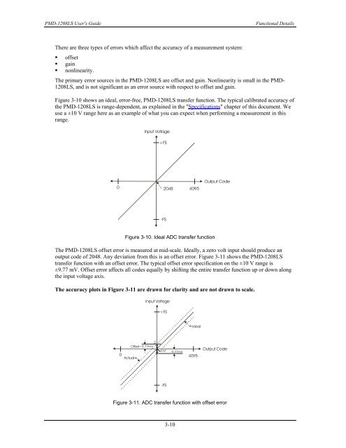
<strong>PMD</strong>-<strong>1208LS</strong> <strong>User's</strong> <strong>Guide</strong>Functional DetailsThere are three types of errors which affect the accuracy of a measurement system:• offset• gain• nonlinearity.The primary error sources in the <strong>PMD</strong>-<strong>1208LS</strong> are offset and gain. Nonlinearity is small in the <strong>PMD</strong>-<strong>1208LS</strong>, and is not significant as an error source with respect to offset and gain.Figure 3-10 shows an ideal, error-free, <strong>PMD</strong>-<strong>1208LS</strong> transfer function. The typical calibrated accuracy ofthe <strong>PMD</strong>-<strong>1208LS</strong> is range-dependent, as explained in the "Specifications" chapter of this document. Weuse a ±10 V range here as an example of what you can expect when performing a measurement in thisrange.Input Voltage+FS0 2048 4095Output Code-FSFigure 3-10. Ideal ADC transfer functionThe <strong>PMD</strong>-<strong>1208LS</strong> offset error is measured at mid-scale. Ideally, a zero volt input should produce anoutput code of 2048. Any deviation from this is an offset error. Figure 3-11 shows the <strong>PMD</strong>-<strong>1208LS</strong>transfer function with an offset error. The typical offset error specification on the ±10 V range is±9.77 mV. Offset error affects all codes equally by shifting the entire transfer function up or down alongthe input voltage axis.The accuracy plots in Figure 3-11 are drawn for clarity and are not drawn to scale.Input Voltage+FSIdeal2Offset=9.77mV20489.77mV0 4095ActualOutput Code-FSFigure 3-11. ADC transfer function with offset error3-10