Reverse electrodialysis: evaluation of suitable electrode systems - ITM
Reverse electrodialysis: evaluation of suitable electrode systems - ITM
Reverse electrodialysis: evaluation of suitable electrode systems - ITM

Create successful ePaper yourself
Turn your PDF publications into a flip-book with our unique Google optimized e-Paper software.
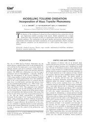
1462 J Appl Electrochem (2010) 40:1461–1474gradient power (SGP). The energy that theoretically can begenerated per m 3 river water is 1.7 MJ when mixed withthe same volume sea water or even 2.5 MJ when mixedwith a large surplus <strong>of</strong> sea water [1]. Post et al. provedexperimentally that it is possible to convert 85% <strong>of</strong> thispotential energy into useful electricity [2]. Wick andSchmitt [3] estimated the total global salinity power to be2.6 TW, which is sufficient to supply the global electricitydemand (2 TW) or 16% <strong>of</strong> the total present energyconsumption [4].There are two membrane technologies capable <strong>of</strong> convertingthis potential energy into electricity: reverse <strong>electrodialysis</strong>(RED) [5–7] and pressure retarded osmosis(PRO) [8, 9]. Both PRO and RED are sustainable technologieswithout CO 2 or other emissions. The only productis brackish water which is also formed when a river flowsdirectly in the sea. Moreover, there is no thermal pollution:the conversion <strong>of</strong> entropy into electrical energy causes aslight decrease <strong>of</strong> the water temperature <strong>of</strong> about 0.1 K ifall the potential energy is extracted [10]. Post et al. [11]showed that in the case <strong>of</strong> using seawater with river water,RED is a good choice. In 1954 Pattle already [5–7] showedthe opportunities <strong>of</strong> this method.A RED stack consists <strong>of</strong> a large number <strong>of</strong> cells. Anexample <strong>of</strong> a RED stack with only one cell is shown inFig. 1. The cell consists (from left to right in the figure) <strong>of</strong>an anion exchange membrane (AEM), a sea water compartment,a cation exchange membrane (CEM) and a riverwater compartment. On the right side, the stack contains anextra AEM. The ions in the sea water diffuse through themembranes to the river water: the Na ? ions through theCEM and the Cl - ions through the AEM. The positive Na ?movement to the right and the negative Cl - movement tothe left add together to a positive ionic current to the right.The electromotive force <strong>of</strong> such a cell is 175 mV if pureNaCl solutions are used <strong>of</strong> 1 and 30 g l -1 and idealmembranes are applied; practical cell voltages under conditions<strong>of</strong> maximal power generation are about 60 mV [1].In practice, a large number <strong>of</strong> cells (N) is used, in the rangefrom 50 in laboratory equipments to 1000 or more incommercial RED plants [1].The N cells together are designed as ‘generating system’(GS). At the <strong>electrode</strong>s, the ionic current is converted intoan electron current. The <strong>electrode</strong> system (ES) consists atleast <strong>of</strong> four parts: (i) <strong>electrode</strong>s, (ii) anolyte and catholyte,(iii) outer membranes, and (iv) technical equipment forrecirculating the <strong>electrode</strong> rinse solution. Eventually the<strong>electrode</strong> rinse solution (pH etc.) is controlled by anadditional system.In principle, the recirculation system <strong>of</strong> the <strong>electrode</strong>rinse solution can cause short-circuiting <strong>of</strong> the RED stack.However, if the resistance <strong>of</strong> this recirculation system ismuch higher then the internal resistance <strong>of</strong> the stack, thisFig. 1 A RED stack with only one celleffect can be ignored. This can be done by applying relativelylong tubes to the recirculating system.The <strong>electrode</strong> system as shown in Fig. 1 is equippedwith inert <strong>electrode</strong>s with a reversible redox couple containingFe 2? /Fe 3? ions in a NaCl–HCl supporting electrolyte.The potential difference needed for reduction <strong>of</strong> Fe 3?to Fe 2? on the cathode is counterbalanced by the oxidation<strong>of</strong> Fe 2? to Fe 3? at the anode. Under zero current conditions,the total cell electromotive force (EMF) is obtainedat the working <strong>electrode</strong>s. The Fe 3? /Fe 2? ratio is keptconstant by recirculation the combined anolyte and catholytethrough the <strong>electrode</strong> compartments. This type <strong>of</strong>redox system is called a homogeneous charge transferreaction because all reactants are present in the same phase.In order to reduce the relative power loss <strong>of</strong> the <strong>electrode</strong>system, RED stacks should have a large number <strong>of</strong> cells.In literature many <strong>electrode</strong> <strong>systems</strong> are described forRED. These <strong>systems</strong> are all used on laboratory scale andnone <strong>of</strong> these <strong>systems</strong> has been evaluated for its practicalapplicability on a real scale. Many aspects <strong>of</strong> the <strong>electrode</strong>system are important for its operation: electrochemicalreactions, energy consumption, transport through themembranes <strong>of</strong> the <strong>electrode</strong> system, reversibility etc. Theobjective <strong>of</strong> this paper is to compare these <strong>electrode</strong> <strong>systems</strong>for their suitability for RED. The evaluated <strong>systems</strong>include those already described in literature, but alsocontains <strong>electrode</strong> <strong>systems</strong> as used in supercapacitors,redox flow battery, <strong>electrodialysis</strong> and capacitive deionization,which might also be useful for RED.123
J Appl Electrochem (2010) 40:1461–1474 14632 Electrode <strong>systems</strong> for RED2.1 Classical <strong>systems</strong>To be fair to the pioneers <strong>of</strong> RED, it should be mentionedthat their <strong>electrode</strong> <strong>systems</strong> were designed for laboratoryuse and were not developed for real applications. However,we have used their <strong>systems</strong> in our comparison because theirsolutions vary so widely.2.1.1 OverviewTable 1 shows the different published <strong>electrode</strong> <strong>systems</strong> forRED. These <strong>electrode</strong> <strong>systems</strong> can be classified into twogroups: with or without opposite <strong>electrode</strong> reactions. First,for <strong>systems</strong> with opposite <strong>electrode</strong> reactions and a recirculating<strong>electrode</strong> rinse, there is no net chemical reaction.These <strong>systems</strong> have a zero equilibrium voltage. A REDsystem with such an <strong>electrode</strong> system can generate electricalenergy with only a few cells because there is noenergy consumption for a net chemical reaction. Anotheradvantage is that there is no loss <strong>of</strong> chemicals (except fortransport through the outer membranes) and no gas production.Pattle [6, 7] used copper gauze <strong>electrode</strong>s in aCuSO 4 solution. On the cathode the dissolved Cu 2? wasreduced to metallic copper and at the anode the copper wasoxidized to Cu 2? . With a typical RED current density <strong>of</strong>5mAcm -2 this effect on the thickness <strong>of</strong> <strong>electrode</strong>s isabout 2 mm per week. Jagur-Grodzinski and Kramer [12]and Audinos [13, 14] used zinc <strong>electrode</strong>s with a ZnSO 4<strong>electrode</strong> rinse solution. In another experiment Audinosused Ag/AgCl <strong>electrode</strong>s in a NaCl solution [13, 14].In all these processes the <strong>electrode</strong>s play an active rolein the redox process: one <strong>electrode</strong> is growing and the otheris dissolving. In such <strong>systems</strong> the feed waters should beinterchanged periodically to invert the direction <strong>of</strong> theelectrical current and with that the <strong>electrode</strong> processes.This imposes limitations on the stack design: the stackshould be equipped with identical sea and river watercompartments. A less attractive solution is to mechanicallyperform the periodical interchange <strong>of</strong> anode and cathode.This reversal can be avoided by taking a homogeneousredox couple with inert <strong>electrode</strong>s. This may be platinizedtitanium for both <strong>electrode</strong>s, special coated titanium forspecific anode and cathode and carbon or steel for thecathode. Jagur-Grodzinski and Kramer used platinizedcarbon <strong>electrode</strong>s in their so called ‘REF system’, a combination<strong>of</strong> a RED system and the <strong>electrode</strong> system <strong>of</strong> afuel cell. At the anode water is oxidized to O 2 and at thecathode oxygen from air is reduced to water. Because the<strong>electrode</strong> solution contained NaCl, it is also possible thatCl 2 is evolved at the anode. Veerman et al. used a systemwith FeCl 2 and FeCl 3 in a NaCl bulk as described in Sect.2.2.1, the system K 4 Fe(CN) 6 with K 3 Fe(CN) 6 in a NaClbulk [1, 15] and also a H 2 /Cl 2 generating system with onlyNaCl [10].Second, the alternative for the <strong>systems</strong> with opposite<strong>electrode</strong> reactions are the <strong>systems</strong> with gas generation.The disadvantage <strong>of</strong> these <strong>systems</strong> is the loss <strong>of</strong> energy dueto these reactions; a significant number <strong>of</strong> cells should beused to overcome the cell equilibrium voltage beforeelectricity production is possible. On laboratory scale theproblem can be solved by using a small number <strong>of</strong> cellstogether with an external power supply. The virtual REDvoltage (the voltage without the losses at the <strong>electrode</strong>s) isobtained from a pair <strong>of</strong> reference <strong>electrode</strong>s in the <strong>electrode</strong>compartments near to the outer membranes. Weinsteinand Leitz [16], Wick [17], Loeb [18], Metha [19] andSuda et al. [20] reported such <strong>systems</strong>. At the cathodehydrogen is evolved and at the anode chlorine is evolved ifa NaCl solution (or sea water) is used in the <strong>electrode</strong>compartments. A possible succeeding reaction is hypochloriteand chlorate formation [21]. Turek et al. avoidedthe formation <strong>of</strong> chlorine by using an <strong>electrode</strong> rinsesolution with Na 2 SO 4 [22, 23]. In this case oxygen isgenerated at the anode.2.1.2 Membranes <strong>of</strong> the described <strong>electrode</strong> <strong>systems</strong>The sequence <strong>of</strong> the membranes in a RED stack is alwaysalternating, but for the outer membranes—confining the<strong>electrode</strong> system—there are some requirements. The <strong>systems</strong>described in literature are given in Table 1. Someauthors (Weinstein and Leitz [16] and Suda et al. [20])used seawater in the <strong>electrode</strong> compartments and appliedtwo different outer membranes, ensuring in this way analternating system <strong>of</strong> sea and river water compartments.However, the generated Cl 2 and ClO - are discharged intothe sea water which is unacceptable from the viewpoint <strong>of</strong>safety, health and environment (SHE). Also the formation<strong>of</strong> Cl 2 requires the application <strong>of</strong> chlorine resistant outermembranes.Another possibility is to use a closed <strong>electrode</strong> system.Veerman et al. [15] used a closed <strong>electrode</strong> rinse containingNaCl with CEMs as outer membranes. In this case thenegative ClO - is confined together with the Cl 2 in the<strong>electrode</strong> rinse. Although there is no direct discharge <strong>of</strong>these products to sea water, the problem <strong>of</strong> disposing thesechemicals is not solved. Pattle [7] used a CuSO 4 solutionand in Table 1 it is seen that the Cu 2? -ions are maintainedin the <strong>electrode</strong> compartments by the outer AEMs. Although an AEM (with positively fixed charges) is slightlypermeable for monovalent (positive) co-ions, the bivalentpositively charged Cu 2? -ions are strongly excluded andCu 2? -loss is expected to be relatively low but not to benegligible in terms <strong>of</strong> SHE. The SO 4 2- in the <strong>electrode</strong>123
1464 J Appl Electrochem (2010) 40:1461–1474Table 1 Electrode <strong>systems</strong> described in literatureanode anolyte repeating catholyte cathode author+ bulk unit + bulk <strong>electrode</strong> reactionsdescribed <strong>systems</strong> in literature1 Cu CuSO 4‡ S R ‡ CuSO 4Cu Pattle [5,6,7]cath.: Cu 2+ + 2e CuCl – Na + Cl – anode: Cu Cu 2+ + 2enet: nil2 metal sea S R ‡ sea metal Weinstein/Leitz [16]cath.: 2 H 2O + 2e H 2+ 2OH –Na + Cl – anode: 2 Cl – Cl 2+ 2enet: 2H 2O + 2 Cl – H 2+ 2OH – + Cl 23 Ag/AgCl NaCl ‡ S R ‡ NaCl Ag/AgCl Audinos [13,14]cath.: AgCl + e Ag + Cl –Cl – Na + Cl – anode: Ag + Cl – AgCl + enet: nil4 Zn ZnCl 2‡ S R ‡ ZnCl 2Zn Jagur–Grodzinski/Kramer [12]cath.: Zn 2+ + 2e ZnCl – Na + Cl – anode: Zn Zn 2+ + 2enet: nil5 C/Pt NaCl R ‡ S R ‡ NaCl C/Pt Jagur–Grodzinski/Kramer [12]air cath.: ½O 2+ 2H + + 2e H 2ONa+ Cl – Na + Cl – anode: H 2O ½O 2+ 2H + + 2eand 2Cl – Cl 2+ 2eseparated anolyte and catholyte6 Ti/Pt Na 2SO 4R ‡ S Na 2SO 4Ti/Pt Turek [22, 23]cath.: 2H 2O + 2e H 2+ 2OH –Na+ Cl – Na + anode: H 2O ½ O 2+ 2 H + + 2enet: H 2O + 2 H 2+ ½ O 27 C sea S R ‡ sea C Suda [20]cath.: 2 H 2O + 2e H 2+ 2OH –Na + Cl – anode: 2Cl – Cl 2+ 2enet: 2H 2O + 2 Cl – H 2+ 2OH – + Cl 2used <strong>systems</strong> by author8 Ti/RuIr Fe 2+ /Fe 3+ ‡ S R ‡ Fe 2+ /Fe 3+ Ti/RuIr Veerman et al. [this paper]NaCl / HCl NaCl / HCl cath.: Fe 3+ + e Fe 2+Cl – Na + Cl – anode: Fe 2+ Fe 3+ + enet: nil9 Ti/RuIr3–Fe(CN) 6/ R ‡ S3–Fe(CN) 6/ Ti/RuIr Veerman et al. [1,15]4–Fe(CN) 64–Fe(CN) 63–cath.: Fe(CN) 6+ e4–Fe(CN) 6NaCl Na + Cl – Na + NaCl4–anode: Fe(CN) 63–Fe(CN) 6+ enet: nil10 Ti/RuIr NaCl R ‡ S NaCl Ti/RuIr Veerman et al. [10]4–Fe(CN) 6cath.: 2 H 2O + 2e H 2+ 2OH –Na + Cl – Na + NaCl anode: 2Cl – Cl 2+ 2enet: 2H 2O + 2 Cl – H 2+ 2OH – + Cl 2suggested <strong>systems</strong>11 graphite Fe 2+ /Fe 3+ ‡ S R ‡ Fe 2+ /Fe 3+ graphite Veerman et al. [this paper]NaCl / HCl NaCl / HCl cath.: Fe 3+ + e Fe 2+Cl – Na + Cl – anode: Fe 2+ Fe 3+ + enet: nil12 graphite3–Fe(CN) 6/ R ‡ S3–Fe(CN) 6/ graphite Veerman et al. [this paper]4–Fe(CN) 64–Fe(CN) 63–cath.: Fe(CN) 6+ e4–Fe(CN) 6NaCl Na + Cl – Na + NaCl4–anode: Fe(CN) 63–Fe(CN) 6+ enet: nilis the anode, cathode, cation exchange membrane and ‡ anion exchange membrane. The repeating unit is underlined.S stands for sea waterand R for river water. Direction <strong>of</strong> the ions through the membranes is designated by arrows123
J Appl Electrochem (2010) 40:1461–1474 1465system will be exchanged rapidly for Cl - from the seawater. This exchange has no effect on the functioning <strong>of</strong>the system as long as the Cu 2? ions stay in the <strong>electrode</strong>compartments.Jagur-Grodzinski and Kramer [12] also used active metal<strong>electrode</strong>s (zinc) but their design was improved by takingCl - as anion. Turek and Bandura [22] described a systemwith a Na 2 SO 4 <strong>electrode</strong> rinse in combination with anionexchange outer membranes, evolving H 2 at the cathode andin first instance O 2 at the anode. In such <strong>systems</strong> the SO 42-can be exchanged for Cl - . This can cause generation <strong>of</strong> Cl 2because after some time there is enough Cl - in the <strong>electrode</strong>rinse solution ([5 gl -1 ) to generate Cl 2 .We conclude: if there is a closed <strong>electrode</strong> rinse loop, itis possible to contain only one type <strong>of</strong> ion (anion or cation)in the combined <strong>electrode</strong> compartments. In this case, theouter membranes should be <strong>of</strong> the same kind (both AEM orboth CEM) and the ionic charge transport between thewater compartments to the <strong>electrode</strong> rinse solution is donerespectively by Cl - or by Na ? .2.2 Self-developed <strong>systems</strong>In our laboratory, we used three different <strong>electrode</strong> rinsesolutions, always with the same DSA (dimensionally stableanode) type <strong>electrode</strong>s: titanium mesh <strong>electrode</strong>s, coatedwith Ru–Ir mixed metal oxides. These <strong>electrode</strong>s are<strong>suitable</strong> as anode as well as cathode and therefore currentreversal is allowed. The first <strong>electrode</strong> rinse solution wasunpractical for laboratory use; the other two are describedin the different articles on RED performance [1, 10, 15].2.2.1 Fe 2? /Fe 3? in NaCl–HClIn order to avoid the large overvoltages <strong>of</strong> gas generating<strong>systems</strong>, we first used the system Fe 2? /Fe 3? in a NaCl bulktogether with the mentioned inert <strong>electrode</strong>s. For an <strong>electrode</strong>rinse containing FeCl 2 (0.05 mol l -1 ), FeCl 3(0.05 mol l -1 ) and NaCl (0.5 mol l -1 ), the resulting pHwas 2.4. The disadvantage <strong>of</strong> this system is that O 2 oxidizesFe 2? to Fe 3? and H ? diffuses through the outermembranes, both causing an increase <strong>of</strong> the pH. Afterprolonged use, the <strong>electrode</strong> rinse solution obtained a redbrownish color which can be explained by the formation <strong>of</strong>iron(III) oxyhydroxides. Oxidation can be prevented bymeans <strong>of</strong> an airtight system and the formation <strong>of</strong> insolublesalts can be avoided by controlling the pH to a low value(\2.3) by the addition <strong>of</strong> HCl. However, buffering withHCl is difficult because anion exchange membranes aresomewhat permeable for H ? and a constant supply <strong>of</strong> HClis necessary. In this way the pH <strong>of</strong> the effluent decreasesthat which is unacceptable from an environmental viewpoint.A possible solution is the use <strong>of</strong> an external<strong>electrodialysis</strong> system with bipolar membranes, generatingNaOH as well as HCl. The NaOH can be directed to theoutput stream and the HCl to the electrolyte. This processis pH neutral and there are no environmental implications.An internal <strong>electrodialysis</strong> system with bipolar membranes(built in the RED stack) for the same purpose is patented byHamelers et al. [24].2.2.2 [Fe(CN) 6 ] 4- /[Fe(CN) 6 ] 3- in NaClFor the development and testing <strong>of</strong> RED <strong>systems</strong> in thelaboratory the Fe 2? /Fe 3? appeared to be rather unpractical.Therefore, we changed to a quite stable system: the ironhexacyan<strong>of</strong>errate system: 3 4FeðCNÞ 6 þ e FeðCNÞ6;E 0 ¼ 0:356 V vs: SHE:This system is described in former articles [1, 15].Again, the inert <strong>electrode</strong>s were used as described in Sect.2.2. To prevent loss <strong>of</strong> the iron complex we used CEMs asouter membranes. As long as the electrolyte is not incontact with the AEMs, there are no problems to beexpected. However, in case <strong>of</strong> internal leakages,hexan<strong>of</strong>errate ions may poison the AEMs in the stack byirreversible binding, eventually resulting in a decreasedperformance [25].2.2.3 NaClTo prevent the poisoning <strong>of</strong> the membranes, we changed toa pure NaCl solution in the <strong>electrode</strong> compartments. Withthis system, we characterized some membrane pairs for theuse in RED stacks [10]. By applying CEMs as outermembranes, the generated Cl 2 and OCl - was kept withinthe <strong>electrode</strong> system.2.3 Proposal for a novel system: Fe 2? /Fe 3?in NaCl–HCl with graphite <strong>electrode</strong>sThe formerly used DSA type <strong>electrode</strong>s (as described in Sect.2.2) are designed for gas generation with low overvoltages.However, in our <strong>electrode</strong> <strong>systems</strong> with a reversible redoxcouple (the Fe 2? /Fe 3? system and the [Fe(CN) 6 ] 4- /[Fe(CN) 6 ] 3- system) gas evolution is undesirable.Therefore, we suggest the use <strong>of</strong> graphite <strong>electrode</strong>s inthese <strong>systems</strong>. Graphite <strong>electrode</strong>s have been extensivelystudied for use in redox flow batteries. One <strong>of</strong> these energystorage <strong>systems</strong>—the Fe/Cr system—uses the Fe 2? /Fe 3?couple in the positive half-cell at low pH. It appears thatthis system is well reversible in electrochemical sense [26].Graphite felt is tested until current densities <strong>of</strong>700 mA cm -2 [27] whereas the optimal current density at123
1466 J Appl Electrochem (2010) 40:1461–1474RED is much lower; Veerman et al. reported 4 mA cm -2for their experiments whereas an improvement with afactor 5 is expected in the future with high performancemembranes and spacers [1].Advantages <strong>of</strong> carbon <strong>electrode</strong>s to Ti/Ru/Ir <strong>electrode</strong>sare:– No use <strong>of</strong> exhaustible precious metals.– High overpotentials for gas formation.There is no risk <strong>of</strong> evolvement <strong>of</strong> dangerous andaggressive gasses (H 2 ,O 2 and Cl 2 ). Even with a reversibleredox couple this may be the case if the flow <strong>of</strong> the <strong>electrode</strong>rinse solution is obstructed locally.A disadvantage <strong>of</strong> graphite may be the lower mechanicalstability with respect to DSA-type <strong>electrode</strong>s during longeroperation times and the need for a proper current collectingsystem. Therefore, graphite <strong>electrode</strong>s may be advantageousfor the Fe 2? /Fe 3? system as well as for the[Fe(CN) 6 ] 4- /[Fe(CN) 6 ] 3- system. We added such <strong>systems</strong>to Table 3 (column 11 and 12). The rather good end scoresencourages further research on these <strong>systems</strong>.2.4 Symmetry in RED stacksIf the sea and river water inlets <strong>of</strong> a RED stack are interchanged,the polarity <strong>of</strong> the generated voltage is reversed.Consequently, the performance <strong>of</strong> the RED stack is unalteredif the generating system (GS) and the <strong>electrode</strong> system(ES) are both symmetrical. It is evident that thesymmetrical properties <strong>of</strong> GS and ES are related.2.4.1 Reversal <strong>of</strong> the electrical currentFor some <strong>electrode</strong> <strong>systems</strong> periodical reversal is obligatoryas for <strong>systems</strong> with participating (one dissolving andone growing) <strong>electrode</strong>s. These <strong>electrode</strong> <strong>systems</strong> aredesignated as ‘obligatory reversal’ or ES 1 . Other <strong>systems</strong>consist <strong>of</strong> ‘universal’ <strong>electrode</strong>s where reversal is possiblebut not obligatory and are called ‘facultative reversal’ orES 2 . A third case consists <strong>of</strong> the specific <strong>electrode</strong>s that areonly <strong>suitable</strong> as cathode or as anode and in which reversal<strong>of</strong> the electrical current is not possible. These are denotedas forbidden interchange or ES 3 .2.4.2 Interchange <strong>of</strong> the feed water in RED stacksJust as with the <strong>electrode</strong> system, we distinguish for thegenerating system between three types:GS 1 : obligatory interchangeIn RED, growth <strong>of</strong> microorganisms in the stacks may bea serious problem. One approach to prevent this, is theperiodical interchange <strong>of</strong> the river and sea water inputs. Acomparable method is used for normal <strong>electrodialysis</strong> fordesalination purposes and is called ‘<strong>electrodialysis</strong> reversal’(EDR) [28, 29]. From experiments in the future, it maybe proven that such a procedure is necessary and we denotethis system as ‘obligatory interchange’’ or as GS 1 .GS 2 : facultative interchangeIf it should be proved that feed water interchange is notbeneficial for prevention <strong>of</strong> microbial growth or forbreaking down polarization layers, then this interchange isnot obligatory. If, besides that, the GS is symmetrical (withidentical sea and river water compartments), the interchange<strong>of</strong> sea and river water is also not forbidden. In thiscase we have a ‘facultative interchange’ system or GS 2 .GS 3 : forbidden interchangeBottlenecks in stack design for RED are the hydrodynamicalfluid resistance in all compartments and electricalresistance in river water compartments [1]. Optimizationcan lead to an asymmetric stack: sea water compartmentsmay be thicker than river water compartments to reducehydrostatic resistance without affecting electrical resistancesubstantially; also length and width can differ. Insuch a stack interchanging sea and river water is possiblefor cleaning purposes but during this interchange the powerproduction is low. We call this a ‘forbidden interchange’system GS 3 ; although the adjective forbidden should not tobe interpreted strictly.2.5 Voltage losses in <strong>electrode</strong> <strong>systems</strong>Electrode <strong>systems</strong> introduce a voltage loss in the REDsystem due to an overpotential, concentration polarization,an ohmic potential and a Nernst potential in each <strong>electrode</strong>compartment. In RED, current densities are relatively low(in our own experiments about 4 mA cm -2 [1]) and thelosses due to concentration polarization and the ohmicpotential are minimal. This is a general property <strong>of</strong> allstudied <strong>electrode</strong> <strong>systems</strong> for RED. Further, with respect tovoltage losses, these <strong>systems</strong> can be divided in low, highand medium loss <strong>electrode</strong> <strong>systems</strong>.Low loss In <strong>systems</strong> with opposite <strong>electrode</strong> reactionsand a recirculating <strong>electrode</strong> rinse, there is no net chemicalreaction and the Nernst voltages on both <strong>electrode</strong>s canceleach other. In most <strong>of</strong> these <strong>systems</strong> no gas reactions areinvolved and the overpotentials are low. The total voltageloss in the whole <strong>electrode</strong> system is about 0.1 V; which iscomparable to the generated voltage <strong>of</strong> 1-2 cells.High loss Electrode <strong>systems</strong> with gas evolution havehigher voltage losses. For the electrolyses <strong>of</strong> water, theneeded voltage based on the Nernst equation is 1.23 V, andthe overpotentials are 0.03 V for H 2 and 0.52 V for O 2evolution at a current density <strong>of</strong> 10 mA cm -2 [30], together1.78 V. Because the typical cell voltage is about 60 mVunder power generating circumstances, a number <strong>of</strong> 30 cellsis used to overcome the voltage loss <strong>of</strong> this <strong>electrode</strong> system.123
J Appl Electrochem (2010) 40:1461–1474 1467Medium loss A special case is the so called ‘REF system’<strong>of</strong> Jagur-Grodzinski and Kramer [12] (system 5 inTable 1). At the anode O 2 is evolved and at the cathode O 2is consumed, so there is no net generation <strong>of</strong> O 2 . Becausethere are separated anode and cathode compartments, thenet reactions is: H 2 O ? H ? ? OH - . This water dissociationin ions consumes about 15 kJ mol -1 [31], muchlower than the 286 kJ mol -1 as necessary for splitting <strong>of</strong>water in H 2 and O 2 [32]. Therefore, this system is classifiedin the category ‘medium loss’.It should be noted that <strong>electrode</strong> losses are onlyimportant in stacks with a small number <strong>of</strong> cells as inlaboratory equipments. In a stack with 1000 cells the loss<strong>of</strong> a high loss system is only 3%. High loss <strong>systems</strong> areassessed with minus 1 point with respect to low loss <strong>systems</strong>(Sect. 3.2.1.5 and Appendix A 5 ).3 Criteria for <strong>electrode</strong> <strong>systems</strong>3.1 Method <strong>of</strong> assessmentIn the assessment <strong>of</strong> <strong>electrode</strong> <strong>systems</strong>, all relevant aspectsconcerning safety, health, environment (SHE), technicalfeasibility and economics are taken into account. In total 13<strong>of</strong> these aspects were considered. A judgment in a scalefrom 0 (unacceptable) to 5 (good) is given. Because acommercial RED power plant was never built so far, thereis no experience with the different <strong>systems</strong> under realeconomical power producing circumstances. Nine different<strong>electrode</strong> <strong>systems</strong> for RED are described in literature. Torank the quality <strong>of</strong> different <strong>systems</strong>, there are a largenumber <strong>of</strong> methods. Data envelopment analysis (DEA) is apowerful method, especially because the different weightfactors are determined by the method itself. However, theconsequence is that the method is only applicable if thenumber <strong>of</strong> <strong>systems</strong> is larger than the number <strong>of</strong> the aspects[33, 34] and that is not the case in our current topic.Often a much more simple system is used: the end resultis calculated as the arithmetic mean <strong>of</strong> the different marks.However, to prevent compensation <strong>of</strong> bad marks by othergood aspects, we achieved the total rating by calculatingthe geometric mean A <strong>of</strong> all (n) parts A i . Each aspect A i isjudged with a mark in the range from 0 (unacceptable) to 5(good).A ¼!1 Yn nA ii¼1ð1ÞIn fact, the geometric mean is closely related to thelogarithmic mean with the difference that the first methodcan cope with zeros and the second method cannot. Theadvantages <strong>of</strong> this way <strong>of</strong> ranking are: (i) unacceptable<strong>systems</strong> are mentioned (judged as 0 on a single criterion) butalways remain at the lowest level <strong>of</strong> the ranking, (ii) there isno need for ambiguous weight factors (iii) very differentvariables can be used for different items; even nominal andordinal data can used together (iv) masking bad properties byaveraging with good properties hardly occurs.For most items, the generating system (N cells <strong>of</strong> thestack) is independent <strong>of</strong> the <strong>electrode</strong> system: each generatingsystem can be combined with each <strong>electrode</strong> system.An important exception to this rule is the aspect <strong>of</strong> feed waterinterchange as discussed in Sect. 3.2.1.1. This aspect requiresa separate ranking system for stacks with obligatory, facultativeand forbidden river and sea water interchange.3.2 Assessed aspectsIn this paragraph, different aspects are summarized.Applied criteria are included in the appendix. Aspects areclassified in three groups: (i) technical feasibility (5aspects), (ii) safety, health and environment (SHE; 5aspects) and (iii) economics (3 aspects). A larger number <strong>of</strong>aspects in a group make this group more important in theend score. Sometimes the classification is rather arbitrary.3.2.1 Technical feasibility3.2.1.1 Reversal <strong>of</strong> the electrical current/interchange <strong>of</strong>the feed water Discussed in Sect. 2.4 are three types <strong>of</strong><strong>electrode</strong> <strong>systems</strong> and three types <strong>of</strong> generating <strong>systems</strong>.Interchange <strong>of</strong> the feed water <strong>of</strong> a GS has consequences forthe <strong>electrode</strong> system: by the reversal <strong>of</strong> the direction <strong>of</strong> theelectrical current the anode becomes cathode and viseversa. Table 2 shows the scores <strong>of</strong> the different combinations.All combinations are permitted except GS 3 -ES 1 .The combination GS 1 –ES 3 is not strictly forbiddenbecause the following reason. Most modern <strong>electrode</strong>s aredesigned specifically as cathode or as anode. Cathodes canbe made <strong>of</strong> different materials like stainless steel andgraphite; however, the requirements for anodes are muchhigher than for cathodes. Special mixed metal oxide <strong>electrode</strong>sbased on thin layers <strong>of</strong> precious metals on titaniumcan act both as anode and as cathode but their lifetime isTable 2 Marking the different combinations <strong>of</strong> generating <strong>systems</strong>with <strong>electrode</strong> <strong>systems</strong>Reversal <strong>of</strong> the electrical currentES 1 :obligatory ES 2 : facultative ES 3 : forbiddenInterchange <strong>of</strong> the water inletsGS 1 : obligatory 4 5 1GS 2 : facultative 5 5 5GS 3 : forbidden 0 5 5123
1468 J Appl Electrochem (2010) 40:1461–1474severely lowered if current reversal is applied [35, 36]. Insome patents for <strong>electrodialysis</strong> (ED), <strong>systems</strong> are describedwith composite <strong>electrode</strong>s [37–39]. These <strong>electrode</strong>s consist<strong>of</strong> an alternate array <strong>of</strong> strips <strong>of</strong> anode and cathode material.The power supply can be connected to the proper array oneach side, dependent on the electrical current direction. Inthis way each used <strong>electrode</strong> material, as used in normalED, can also be used also in the EDR mode, an ED methodwhere the current is reversed periodically to prevent scalingon the membranes. Composite <strong>electrode</strong>s can be used inprinciple also for RED to cope with current reversal due tointerchange <strong>of</strong> sea water and river water. Therefore, this‘forbidden’ combination GS 1 –ES 3 is judged with 1 point.The combination GS 1 –ES 1 is not definitely idealbecause the GS and the ES may demand different switchfrequencies and therefore, only 4 points are noted.3.2.1.2 Stability <strong>of</strong> anolyte/catholyte Most anolytes/catholytes as listed in Table 1, contain only stable inorganicions. The exception is the electrolyte with thehexacyan<strong>of</strong>errate redox system. The complex ions in thissolution are able to decompose and to form stable insolublecomplexes with many multivalent metal ions with the risk<strong>of</strong> poisoning the membranes.3.2.1.3 Gas formation at the <strong>electrode</strong>s Gas formation(Cl 2 and O 2 at the anode and H 2 at the cathode) can causeproblems at the <strong>electrode</strong>s (electrical obstruction) and Cl 2is highly corrosive. Besides this, Cl 2 formation has anegative environmental value (again called in aspect B 3 )and H 2 is an explosion hazard (again called in aspect B 1 ).3.2.1.4 Participating <strong>electrode</strong>s Participating <strong>electrode</strong>sare already counted at the reversal item. However, dissolvingand plating (growing) should be reversible manythousand times. For example, it is known that Zn in thisway is a difficult metal and special provisions should betaken with the <strong>electrode</strong> rinse.3.2.1.5 Electrical properties <strong>of</strong> the <strong>electrode</strong> systemVoltage lossAs stated in Sect. 2.5, <strong>electrode</strong> <strong>systems</strong> can cause low,medium or high losses. If at both <strong>electrode</strong>s oppositeelectrochemical reactions occur in the same electrolyte, thevoltage loss is low; otherwise this loss is high. For a largestack, this voltage loss is a minor problem.Resistance <strong>of</strong> the <strong>electrode</strong> systemElectrodes are normally made from good conductingmaterials. An exception is the Ag/AgCl <strong>electrode</strong> with athick AgCl layer where the Ag ? has to diffuse from thesolution to the Ag surface. This system was described byAudinos [16, 17] and included as system nr. 3 in Table 1.3.2.2 Safety, health and environment3.2.2.1 Safety H 2 is explosive and especially dangerousin closed spaces as sea containers or units for underwateroperation.3.2.2.2 Health Toxicity is judged in case <strong>of</strong> skin and eyecontact, swallowing and inhalation. Especially organicredox couples like hydroquinone/1,4-benzoquinone can bea risk if in contact with the skin. The same holds true foracidified solutions <strong>of</strong> the couple Fe 2? /Fe 3? . Nearly allelectrolytes are toxic if swallowed except NaCl solutions.The most probable danger <strong>of</strong> inhalation is Cl 2 ; HCN can beevolved under extreme conditions (low pH, UV-light) fromthe [Fe(CN) 6 ] 4- /[Fe(CN) 6 ] 3- couple.3.2.2.3 Environment: normal exhaust <strong>of</strong> Cl 2 , ClO - andClO -3 If sea water or NaCl is used in the <strong>electrode</strong>system without a reversible redox couple, Cl 2 can beevolved at the anode and H 2 at the cathode. If anolyte andcatholyte are combined, ClO - is formed and there is thepossibility <strong>of</strong> formation <strong>of</strong> ClO - 3 [21]. Sometimes theseproducts are useful (e.g. as biocide) but mostly they areunwanted. To prevent contamination <strong>of</strong> the outlet streamswith ClO - and ClO - 3 , the outer membranes should be <strong>of</strong>the CEM type. However, due to the non ideal behavior <strong>of</strong>these membranes, there is also a small transport <strong>of</strong> theseanions into the effluent. If other ‘safe’ salts (Na 2 SO 4 ,NaNO 3 etc.) are used in the <strong>electrode</strong> rinse solution, thereis still the danger <strong>of</strong> Cl 2 evolvement because Cl - candiffuse from the sea water compartment to the <strong>electrode</strong>compartment through the CEM.Even in the presence <strong>of</strong> a redox couple, Cl 2 formation isnot excluded totally if Cl - is present in the <strong>electrode</strong> rinsesolution because the redox couple can be exhausted locallydue to obstructions in the flow path in the <strong>electrode</strong>compartment.If seawater is used as electrolyte, there is the possibility<strong>of</strong> a closed <strong>electrode</strong> rinse loop or an open single passsystem. The last system is unacceptable from environmentalviewpoint due to the discharge <strong>of</strong> Cl 2 .3.2.2.4 Environment: normal exhaust other chemicals Inprinciple, ions can be blocked by a proper choice <strong>of</strong> theouter membranes although blocking <strong>of</strong> co-ions is not 100%.Especially protons can easily pass the most types <strong>of</strong> AEMs.Technically, the problems <strong>of</strong> transport from unwantedspecies from the <strong>electrode</strong> compartments to the sea or riverwater compartments and vice versa can be solved by usingdouble outer membranes. Between these outer membranes aguard electrolyte is recirculated. Disadvantageous is theneed <strong>of</strong> conditioning this guard electrolyte.123
J Appl Electrochem (2010) 40:1461–1474 14693.2.2.5 Environment: accidentally exhaust Loss <strong>of</strong> anolyte/catholytemay occur by accident: rupture <strong>of</strong> the outermembranes, human errors and defects in the <strong>electrode</strong> rinsepumping system are possible causes. The effects <strong>of</strong> outermembrane damaging can be decreased by using doubleouter membranes as described above under B 4 . Defects inthe <strong>electrode</strong> rinse system can be controlled by leakagetanks. Moreover, a RED installation is built modular and inevent <strong>of</strong> an accident only a small part <strong>of</strong> the electrolyte isdrained.3.2.3 Economics3.2.3.1 Special provisions for the anolyte/catholyteThe most frequent measures to be taken are:a pH controlAt low pH, H ? can diffuse easily through AEMs to theoutput stream and new H ? should be added to the electrolyte.This can be achieved by adding HCl; an environmentallybetter way is the use an external <strong>electrodialysis</strong>system with bipolar membranes generating NaOH andHCl. The NaOH can be directed in the output stream andthe HCl to the electrolyte. This process is pH neutral.b Redox controlIn redox <strong>systems</strong> as Fe 2? /Fe 3? , the optimal Fe 2? /Fe 3?ratio is about unity. However, by oxidation by air this ratiomay be affected. An airtight system should be used and/ora reduction system should be incorporated.c Concentration controlIn fact, each anolyte/catholyte should be controlled,especially electrolytes containing monovalents ions likeNO 3 - which can be exchanged rapidly with Cl - from thesea water.3.2.3.2 Price <strong>of</strong> the <strong>electrode</strong>s Inert <strong>electrode</strong>s can bemade <strong>of</strong> massive platinum, sometimes with added rutheniumor iridium for mechanical strength. Such <strong>electrode</strong>sare used in laboratories as measuring <strong>electrode</strong> or asworking <strong>electrode</strong> in different analytical processes. These<strong>electrode</strong>s are very expensive and efforts have been madeto platinize other metals or carbon in such a way that theinert properties <strong>of</strong> platinum are combined with the economics<strong>of</strong> other metals. This resulted in platinum coatedtitanium with 20–50 g platinum per square meter. These<strong>electrode</strong>s are rather expensive and not catalytic enough forgas evolving processes. The next step was the invention <strong>of</strong>the so called ‘dimensional stable <strong>electrode</strong>’ (DSA) for thechlor-alkali membrane process [40].Modern stable <strong>electrode</strong>s consist <strong>of</strong> a metal support(mostly titanium) with a mixed metal oxide (MMO) layer[41]. The MMO consist <strong>of</strong> two components: one is a catalyticand conducting (e.g. RuO 2 , IrO 2 , PtO 0.12 ), the otheris inert and nonconducting (e.g. TiO 2 ). The catalytic part <strong>of</strong>the <strong>electrode</strong> cover is developed for special electrochemicalpurposes like Cl 2 or O 2 evolution. On these <strong>electrode</strong>sthe amount <strong>of</strong> precious metal is only 10–12 g m -2 .Moreover the price <strong>of</strong> iridium and especially <strong>of</strong> rutheniumis much lower than <strong>of</strong> platinum. This may result inacceptable prizes.A further reduction <strong>of</strong> <strong>electrode</strong> price can be achievedby using partial <strong>electrode</strong>s: <strong>electrode</strong>s with a reduced surfaceby a proper dimensioning <strong>of</strong> a stretched metal process.In RED, partial <strong>electrode</strong>s can be used because the currentdensity in the RED process is much lower than in otherelectrochemical processes for which these <strong>electrode</strong>s aredeveloped.Graphite <strong>electrode</strong>s are rather inexpensive. However, atlarger surfaces, current collection may be a problem andresults in a higher price.3.2.3.3 Lifetime <strong>of</strong> the <strong>electrode</strong>s Marks for the aspects<strong>of</strong> price (C 2 ) and lifetime (C 3 ) are generally opposite. Inour used criteria (Appendix) all DSA type <strong>electrode</strong>s getthe same judgment (mark = 5). The actual lifetime <strong>of</strong>these <strong>electrode</strong>s is dependent on current direction (anodicor cathodic use), electrolyte and current density. Fields <strong>of</strong>application <strong>of</strong> <strong>electrode</strong>s with long erasing time are waterdesalination with <strong>electrodialysis</strong> (ED) and the chlor-alkaliprocess. In normal ED for desalination, a 5-year life <strong>of</strong> aplatinum plated <strong>electrode</strong> is normal. Anode life was generallyless than cathode life [42]. In fact all modern <strong>electrode</strong>sare MMO covered on titanium (DSA type). Forchlorine evolving DSAs, as used in the chlor-alkaliindustry, typical current densities are more then300 mA cm -2 in the membrane cell process [43]. In thiscase the lifetime <strong>of</strong> DSAs is guaranteed to be up to10 years [44]. In contrast, optimal current densities in ourRED process were 4 mA cm -2 or possibly 20 mA cm -2 inthe future with improved <strong>systems</strong> [1]. Therefore, life time<strong>of</strong> chlorine evolving DSAs may be expected to be muchmore than 10 years for RED. For oxygen evolution, Chenand Chen [45] predicted for their Ti/RuO 2 –Sb 2 O 5 –SnO 2<strong>electrode</strong> a life time <strong>of</strong> 8.3 years at a current density <strong>of</strong>20 mA cm -2 and even 27 years at 10 mA cm -2 . Theselifetimes are also an indication for use in RED <strong>electrode</strong><strong>systems</strong>. The foregoing refers to unidirectional use <strong>of</strong> the<strong>electrode</strong>s. Current reversal (as in EDR) generallydecreases <strong>electrode</strong> lifetime substantially [42, 46].4 Discussion4.1 Described <strong>electrode</strong> <strong>systems</strong>Described <strong>electrode</strong> <strong>systems</strong> in literature for RED are notyet <strong>suitable</strong> for use in economical operated RED <strong>systems</strong>.123
1470 J Appl Electrochem (2010) 40:1461–1474A RED system should fulfill the requirements on safety,health, environment, technical feasibility and economics.In Table 3 the formulated criteria are applied to the differentdescribed <strong>electrode</strong> <strong>systems</strong> from Table 1 (for GS 1in bold, for GS 2 regular and for GS 3 in italics). The row‘reversal to the electrical current’ (A 1 ) is split up in threeparts for the combination <strong>of</strong> the different generating <strong>systems</strong>with the <strong>electrode</strong> system in question. The same goesfor the rows with the end-scores and ranks.Table 3 shows that from the described used <strong>systems</strong>(column 1–10), the iron system with Ti/Ru,Ir <strong>electrode</strong>s(column 8) is the best system in combination with each <strong>of</strong>the three generating <strong>systems</strong>.The hexacyan<strong>of</strong>errate system with the same <strong>electrode</strong>s(column 9) may be useful in laboratory equipment. Thetable also indicates that by application <strong>of</strong> graphite <strong>electrode</strong>sthe score <strong>of</strong> these <strong>systems</strong> is approached (column 11and 12).4.2 Proposal for improved <strong>electrode</strong> <strong>systems</strong>Possible improvements are:a Use <strong>of</strong> graphite <strong>electrode</strong>sAs indicated in Sects. 2.3 and 4.1, the use <strong>of</strong> graphite<strong>electrode</strong>s in combination with homogeneous redox systemlike Fe 2? /Fe 3? has good prospects.b Improved <strong>electrode</strong>s <strong>of</strong> the DSA type– Longer lifetimeFor their experiments Veerman et al. [1, 11, 15] usedtitanium mesh end <strong>electrode</strong>s, coated with Ru–Ir mixedmetal oxides. These <strong>electrode</strong>s are reversible (i.e. currentreversal is possible) and therefore usable for all types <strong>of</strong>stacks. Lifetime <strong>of</strong> these <strong>electrode</strong>s is more than 10 yearsunder the applied current density (4 mA cm -2 ). Animprovement <strong>of</strong> the lifetime with a factor 5 can beachieved with special Ir-MMO (mixed metal oxide) coatedtitanium anodes and Ru-MMO coated cathodes; anotheroption is to use the extra stability <strong>of</strong> these <strong>electrode</strong>s forreducing the cost <strong>of</strong> these <strong>electrode</strong>s by decreasing thesurface <strong>of</strong> the <strong>electrode</strong>s (the so called partial <strong>electrode</strong>s).A limitation <strong>of</strong> this system is that frequent current reversalduring longer times is not possible with these <strong>electrode</strong>s.– High overvoltages for Cl 2 /O 2 evolutionThe success <strong>of</strong> DSA type <strong>electrode</strong>s is due to a combination<strong>of</strong> high mechanical and electrochemical stabilitywith good catalytic properties and low overvoltages forspecial <strong>electrode</strong> reactions. Especially such anodes aredeveloped for Cl 2 and O 2 generation. However, in a REDprocess with a homogeneous redox couple (e.g. the Fe 2? /Fe 3? or the system [Fe(CN) 6 ] 4- /[Fe(CN) 6 ] 3- ), these reactionsare unwanted. Therefore, high overvoltages for gasevolution are favorable to the process. It requires someextra development to realize this with DSA type <strong>electrode</strong>s.– Specific composite <strong>electrode</strong>s for REDFor use in normal <strong>electrodialysis</strong> some <strong>systems</strong> withcomposite <strong>electrode</strong>s are patented [37–39]. These <strong>systems</strong>allow current reversal with <strong>electrode</strong>s which are specificallyusable as cathode or anode. In each current directiononly one part <strong>of</strong> each <strong>electrode</strong> is used. Eventually theunused part can be protected with a low potential differencebetween this part and the adjacent part in operation.c New homogeneous redox coupleHomogeneous redox <strong>systems</strong> (e.g. the system[Fe(CN) 6 ] 4- /[Fe(CN) 6 ] 3- ) do not cause net chemicalreactions and therefore the power losses are low. Mostorganic homogeneous redox couples involve protons intheir reactions and special measures should be taken tocontrol the pH. However, there are many iron complexesand possibly candidates are available that satisfy all mentionedcriteria. The use <strong>of</strong> graphite <strong>electrode</strong>s may beconsidered again in this case.d Capacitive <strong>electrode</strong>sThe last decades, special high ion absorbing carbon hasbeen developed for use in super capacitors [47–50] and incapacitive deionization (CDI) [51, 52]. If this material isused as <strong>electrode</strong> in a RED stack, during a certain time aninternal ionic current can persist. The <strong>electrode</strong>s behave asa capacitor and during that time there is also an externalelectrical current. After some time, the process should beinverted by changing the sea water and the river water feed.It is obvious that the changing time is related to the residencetime in the system. Assuming that time to be 1 min,then a half period (the time between two feed interchanges)should be at least about 60 min. Current RED stacksoperate at maximum power output with a current density <strong>of</strong>about 4 mA cm -2 or 144,000 C m -2 h -1 . The cathodeshould adsorb then 144,000/F = 1.5 mol Na ? and on theanode the same amount <strong>of</strong> Cl - (F is the Faraday constant;1 F = 96,485 C mol -1 ).Typical specific capacitances are reported <strong>of</strong> 100–200 F g -1 carbon in aqueous solution [47–50]. Using thehighest value <strong>of</strong> 200 F g -1 , for an uploading to 1 V, thereis 200 F g -1 carbon needed. For a 1-h operation, the<strong>electrode</strong>s should consist <strong>of</strong> 720 g carbon per m 2 .Thisseems a realistic value for further development <strong>of</strong> such asystem.In principle, the method is very clean and sustainable.Carbon aerogel <strong>electrode</strong>s may have lifetimes <strong>of</strong> more than10 years [53]. A restriction <strong>of</strong> this system is the obligatoryinterchange. For optimal performance, the connected loadshould be adapted continuously during one cycle. This ispossible with modern DC–DC converters. For normal<strong>electrodialysis</strong>, such a system is patented by Wei et al. [54].123
J Appl Electrochem (2010) 40:1461–1474 1471Table 3 Ranking the <strong>systems</strong> described in literature for practical useDescribed <strong>systems</strong> in literature Used <strong>systems</strong> by author Suggested <strong>systems</strong>1 2 3 4 5 6 7 8 9 10 11 12Pattle Weinstein Audinos Jagur-G Jagur-G Turek Suda Veerman Veerman Veerman Veerman VeermanAnolyte/catholyte: CuSO 4 NaCl NaCl ZnCl 2 NaCl Na 2 SO 4 NaCl Fe 3? /Fe 2? HCF b NaCl Fe 3? /Fe 2? HCF bBulk NaCl–HCl NaCl NaCl–HCl NaClCathode: Cu Ti/Pt a Ag/AgCl Zn C/Pt/O 2 Ti/Pt C Ti/Ru,Ir Ti/Ru,Ir Ti/Ru,Ir Graphite GraphiteAnode: Cu Ti/Pt a Ag/AgCl Zn C/Pt Ti/Pt C Ti/Ru,Ir Ti/Ru,Ir Ti/Ru,Ir Graphite GraphiteType: ES1 ES2 ES1 ES1 ES3 ES2 ES2 ES2 ES2 ES2 ES2 ES2Technical feasibilityGS 1 A 1 Reversal <strong>of</strong> the el. current 4 5 4 4 1 5 5 5 5 5 5 5GS 2 A 1 Reversal <strong>of</strong> the el. current 5 5 5 5 5 5 5 5 5 5 5 5GS 3 A 1 Reversal <strong>of</strong> the el. current 0 5 0 0 5 5 5 5 5 5 5 5All A 2 Stability <strong>of</strong> anolyte/catholyte 5 5 5 5 5 5 5 5 3 5 5 3All A 3 Gas formation 5 2 5 5 4 4 2 5 5 2 5 5All A 4 Participating <strong>electrode</strong>s 4 5 3 2 5 5 5 5 5 5 5 5All A 5 Electrical properties 5 4 4 5 3 4 4 5 5 4 5 5Safety, health and environment (SHE)All Bi Hydrogen formation 5 3 5 5 5 3 3 5 5 3 5 5All B 2 Toxicity 4 3 5 4 3 5 3 4 4 3 4 4All B 3 Normal exhaust <strong>of</strong> Cl 2 etc. 5 0 5 5 4 4 0 5 5 1 5 5All B 4 Normal exhaust other chem. 4 5 4 4 5 5 5 4 4 5 4 4All B 5 Accidentally exhaust 3 5 5 4 5 5 5 4 3 5 4 3EconomicsAll C 1 Special provisions 4 3 4 4 2 4 3 3 4 3 3 4All C 2 Price <strong>of</strong> the <strong>electrode</strong>s 5 1 2 5 1 1 5 4 4 4 3 3All C 3 Life time <strong>of</strong> the <strong>electrode</strong>s 2 4 2 2 4 4 2 5 5 5 3 3GS 1 Score 4.1 0.0 3.9 4.0 3.2 3.9 0.0 4.5 4.3 3.5 4.2 4.1Rank 4 11 7 6 10 7 11 1 2 9 3 5GS 2 Score 4.2 0.0 4.0 4.1 3.6 3.9 0.0 4.5 4.3 3.5 4.2 4.1Rank 4 11 7 6 9 8 11 1 2 10 3 5GS 3 Score 0.0 0.0 0.0 0.0 3.6 3.9 0.0 4.5 4.3 3.5 4.2 4.1Rank 8 8 8 8 6 5 8 1 2 7 3 4The marks in the rows A1 are dependent on the generating system (GS 1 ,GS 2 or GS 3 ). The same holds for the score/rank rows at the bottomTi/Pt assumed3- 4-HCF hexacyan<strong>of</strong>errate = Fe(CN) 6 /Fe(CN)6ab123
1472 J Appl Electrochem (2010) 40:1461–1474Brogioli succeeded in the reversal <strong>of</strong> the capacitivedeionization (CD) technique [55]. The capacitor is formedby two activated carbon <strong>electrode</strong>s, immersed in the feedsolution, alternately salt and fresh water. When filled withsalt water, it is charged, and with fresh water it is discharged.Charging and discharging are promoted by thediffusion <strong>of</strong> ions and consequently there is a net energygain.e Systems with an <strong>electrode</strong> rinse solution containingcarbon particles and/or ion exchange resin particlesThese <strong>systems</strong> are described by Kedem et al. for use innormal <strong>electrodialysis</strong> and patented [56, 57]. The <strong>electrode</strong>rinse solution contains about 1% active carbon and 1%cation exchange resin in a NaCl solution <strong>of</strong> about 2%. Theauthors suggest that this system is based on the reversiblesystemH þ þ e 1 = 2 H 2The H 2 gas, as evolved at the cathode is adsorbed by thecarbon and transported to the anode where the reversereaction proceeds. The involved H ? is transported by theion exchange resin:RH þ Na þ RNa þ H þwhere RH is the resin in the acid form and RNa the resin inthe salt form.The net reaction at the cathode and at the anode istherefore:RH þ Na þ þ e RNa þ 1 = 2 H 25 ConclusionsIn this work, self-developed <strong>electrode</strong> <strong>systems</strong> and <strong>electrode</strong><strong>systems</strong> described in literature are compared onsafety, health, environment, technical feasibility and economics.A robust system <strong>of</strong> judging the different <strong>systems</strong> ispresented. Applying this system to the described and used<strong>systems</strong>, a ranking was made <strong>of</strong> the different <strong>electrode</strong><strong>systems</strong>. It is shown that the applicability <strong>of</strong> an <strong>electrode</strong>system is related to the generating system. Three types <strong>of</strong>generating <strong>systems</strong> can be distinguished: <strong>systems</strong> with (i)obligatory, (ii) facultative and (iii) forbidden interchange<strong>of</strong> the feed water inlets. The highest rankings for all thethree generating <strong>systems</strong> are found for the Fe 2? /Fe 3?couple in a NaCl–HCl supporting electrolyte with bidirectionalRu/Ir covered titanium <strong>electrode</strong>s.This system is not ideal and may be improved forapplication in commercial operating, large scale RED.There are five interesting topics: (i) improved stable metal<strong>electrode</strong>s (with longer lifetime, <strong>suitable</strong> for currentreversal and high overpotential for gas evolvement), (ii) anew homogeneous redox couple (e.g. an iron complex),(iii) a system with capacitive <strong>electrode</strong>s, (iv) a system withan electrolyte, containing carbon particles and/or ionexchange resin particles, and (v) the Fe 2? /Fe 3? couple incombination with graphite <strong>electrode</strong>s. The last improvementseems to be the most realistic alternative; however,duration test should be performed under real RED conditionsto prove that it has sufficient mechanical and electrochemicalstability.Acknowledgement This work was performed in the TTIW-cooperationframework <strong>of</strong> Wetsus, centre <strong>of</strong> excellence for sustainablewater technology (www.wetsus.nl). Wetsus is funded by the DutchMinistry <strong>of</strong> Economic Affairs, the European Union Regional DevelopmentFund, the province <strong>of</strong> Fryslân, the city <strong>of</strong> Leeuwarden and theEZ/Kompas program <strong>of</strong> the ‘‘Samenwerkingsverband Noord-Nederland’’.The first author would like to thank the Noordelijke HogeschoolLeeuwarden who facilitated this research by detaching him toWetsus and the participants <strong>of</strong> the theme ‘‘Energy’’ for their fruitfuldiscussions and their financial support.Open Access This article is distributed under the terms <strong>of</strong> theCreative Commons Attribution Noncommercial License which permitsany noncommercial use, distribution, and reproduction in anymedium, provided the original author(s) and source are credited.AppendixApplied criteria.The used marks are: good = 5; reasonable = 4;acceptable = 3; poor = 2; bad = 1 and unacceptable = 0.In some cases minus signs are used. These mean that theirvalue should be subtracted from the maximal score <strong>of</strong> 5.A Technical feasibilityA 1 Reversal <strong>of</strong> the electrical currentscore: Already given in Table 2A 2 Stability <strong>of</strong> the anolyte/catholyteScoreNo instable ions 5[Fe(CN) 6 ] 4- , [Fe(CN) 6 ] 3- 4A 3 Gas formation at the <strong>electrode</strong>sScoreNo gas 5O 2 formation -1Cl 2 formation -2H 2 formation -1A 4 Participating <strong>electrode</strong>sScoreNo participating <strong>electrode</strong>s 5Participating without problems (Cu) 4123
J Appl Electrochem (2010) 40:1461–1474 1473AppendixcontinuedAppendixcontinuedParticipating with minor problems (Ag/AgCl) 3Participating with more severe problems (Zn) 2Participating with severe problems 0A 5 Electrical properties <strong>of</strong> the <strong>electrode</strong> systemScoreNo problems 5Net chemical reaction -1High overvoltage -1Slow redox couple -1High <strong>electrode</strong> resistance -1B Safety, health and environmentB 1 Hydrogen formation at the cathodeScoreNo gas5formationH 2 formation 3B 2 ToxicityScoreNo danger 5Skin danger -1Swallowing danger -1Inhalation danger -2Quinone, pyrocatechol, hydroquinone etc. 2C EconomicsC 1 Special provisions for the anolyte/catholyteScoreNo provisions 5pH control -1Concentration control -1Air supply -1Cl 2, ClO - and ClO - 3 discharge -2C 2 Price <strong>of</strong> the <strong>electrode</strong>sScoreTi, C, Zn, Cu 5DSA type 4Graphite 3Ag 2Platinized Ti or C 1C 3 Lifetime <strong>of</strong> the <strong>electrode</strong>sScoreDSA type 5Platinized Ti or C 4Graphite 3Participating <strong>electrode</strong>s, carbon 2B 3 Environment: normal exhaust <strong>of</strong> Cl 2, ClO - and ClO 3-ScoreNo Cl 2 generation 5Minor Cl 2 production in closed circuit 4Major Cl 2 production in closed circuit 1Minor Cl 2 production in open system 1Major Cl 2 production in open system 0B 4 Environment: normal exhaust other chemicalsScoreNo emission 5Low emission 4Above emission0normB 5 Environment: accidentally exhaustScoreNa ? ,Cl - , HCO - 3 ,Mg 2? ,Ca 2? 5Zn 2? ,Fe 2? ,Fe 3? 4[Fe(CN) 6 ] 4- , [Fe(CN) 6 ] 3- ,Cu 2? 3References1. Veerman J, Metz SJ, Saakes M, Harmsen GJ (2009) J Membr Sci327:1362. Post JW, Hamelers HVM, Buisman CJN (2008) Environ SciTechnol 42:57853. Wick GL, Schmitt WR (1977) Mar Technol Soc J 11:164. Energy information administration; www.eia.doe.gov5. Pattle RE (1954) Nature 174:6606. Pattle RE (1955) Chem Proc Eng 35:3517. Pattle RE (1955) Patent GB 731.7298. Loeb S (1975) Science 189:6549. Loeb S (1976) J Membr Sci 1:4910. Veerman J, de Jong RM, Saakes M, Metz SJ, Harmsen GJ (2009)J Membr Sci 343:711. Post JW, Veerman J, Hamelers HVM, Euverink GJW, Metz SJ,Nymeijer K, Buisman CJN (2007) J Membr Sci 288:21812. Jagur-Grodzinski J, Kramer R (1986) Ind Eng Chem Process DesDev 25:44313. Audinos R (1983) J Power Sources 10:203 (In French)14. Audinos R (1992) Ind J Chem 31A:34815. Veerman J, Post JW, Metz SJ, Saakes M, Harmsen GJ (2008) JMembr Sci 310:41816. Weinstein JN, Leitz FB (1976) Science 191:557123
1474 J Appl Electrochem (2010) 40:1461–147417. Wick GL (1978) Energy 3:9518. Loeb S (1979) Patent US 4.171.40919. Metha GD (1982) J Membr Sci 11:10720. Suda F, Matsuo T, Ushioda D (2007) Energy 32:16521. Czarnetzki LR, Janssen LJJ (1992) J Appl Electrochem 22:31522. Turek M, Bandura B (2007) Desalination 205:6723. Turek M, Bandura B, Dydo P (2008) Desalination 221:46224. Hamelers HVM, Post JW, Metz SJ (2007) Patent WO 2007/094659 A125. Lacey RE (1980) Ocean Eng 7:126. Lopez-Atalaya M, Codina G, Perez JR, Vazquez JL, Aldaz A(1992) J Power Sources 39:14727. Pupkevich V, Glibin V, Karamanev D (2007) ElectrochemCommun 9:192428. Katz WE (1979) Desalination 28:3129. Grebenyuk VD, Grebenyuk OV (2002) Russ J Electrochem38:90630. International Critical Tables (1929) 6:33931. Nagasubramanian K, Chlanda FP, Liu Kang-Jen (1977) J MembrSci 2:10932. Lide DR (ed) (2004) Handbook <strong>of</strong> chemistry and physics, vol 5,85th edn. CRC press, Boca Raton, pp 1833. Charnes A, Cooper WW, Rhodes E (1978) Eur J Oper Res 2:42934. Adler N, Friedman L, Sinuany-Stern Z (2002) Eur J Oper Res140:24935. Qu J-X, Liu S-M (1983) Desalination 46:23336. Kuhn AT, Mortimer CJ (1972) J Appl Electrochem 2:28337. Chen W K-W (1965) Patent US 3,192,14838. Mihara K, Kato M, (1969) Patent US 3,453,20139. Jain SM (1984) Patent US 4,461,69340. Beer HB, US Appl. 549 194 (1966), US 3632498 (1972) and US3711 385 (1973)41. Comninellis CH, Vercesi GP (1991) J Appl Electrochem 21:33542. Price K (ed) (2003) Desalination handbook for planners, 3rd edn.RosTek Associations, Tampa, Florida43. O’Brien TF, Bommaraju TV, Hine F (2005) Handbook <strong>of</strong> chloralkalitechnology, vol 1. Springer, Berlin, p 3344. Trasatti S (2000) Electrochim Acta 45:237745. Chen X, Chen G (2005) Electrochim Acta 50:415546. Kraft A (2008) Platinum Metals Rev 52:17747. Lota G, Centeno TA, Frackowiak E, Stoeckli F (2008) ElectrochimActa 53:221048. Frackowiak E, Béguin F (2001) Carbon 39:93749. Gamby J, Taberna PL, Simon P, Fauvarque JF, Chesneau M(2001) J Power Sources 101:10950. Kim C, Choi YO, Lee WJ, Yang KS (2004) Electrochim Acta50:88351. Farmer JC, Fix DV, Mack GV, Pekala RW, Poco JF (1996) JElectrochem Soc 143:15952. Zou L, Li L, Song H, Morris G (2008) Water Res 42:234053. Welgemoed TJ, Schutte CF (2005) Desalination 183:32754. Wei C, Yu D, Wei C, Xiong R, Cao L (2008) Patent WO 2008/030646 A255. Brogioli D (2009) Phys Rev Lett 103:058501-156. Kedem O, Tanny G, Maoz Y (1978) Desalination 24:31357. Kedem O, Robinson T (1978) Patent US 4.226.688123