
You also want an ePaper? Increase the reach of your titles
YUMPU automatically turns print PDFs into web optimized ePapers that Google loves.
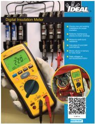
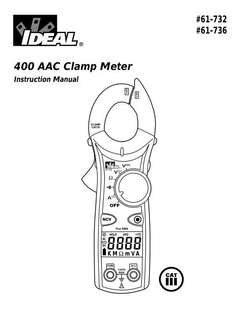
#61-732#61-736400 AAC Clamp MeterInstruction <strong>Manual</strong>ACHOLDAPODCKMΩ mVA
WARNINGRead First: Safety InformationUnderstand and follow operating instructions carefully. Use the meter only asspecified in this manual; otherwise, the protection provided by the meter may beimpaired.WARNINGTo avoid possible electric shock, personal injury or death, follow theseguidelines:• Do not use if meter appears damaged. Visually inspect the meter to ensurecase is not cracked and back case is securely in place.• Inspect and replace leads if insulation is damaged, metal is exposed, or probesare cracked. Pay particular attention to the insulation surrounding theconnectors.• Do not use meter if it operates abnormally as protection maybe impaired.• Do not use during electrical storms or in wet weather.• Do not use around explosive gas, dust, or vapor.• Do not apply more than the rated voltage to the meter.• Do not use without the battery and the back case properly installed.• Remove the test leads from the circuit prior to removing battery cap.• Do not attempt to repair this unit as it has no user-serviceable parts.Page 2
CAUTIONTo protect yourself, think "Safety First":• Voltages exceeding 30VAC or 60VDC pose a shock hazard so use caution.• Use appropriate personal protective equipment such as safety glasses, faceshields, insulating gloves, insulating boots, and/or insulating mats.• Before each use:- Perform a continuity test by touching the test leads together to verify thefunctionality of the battery and test leads.- Use the 3 Point Safety Method. (1) Verify meter operation by measuring aknown voltage. (2) Apply meter to circuit under test. (3) Return to theknown live voltage again to ensure proper operation.• Never ground yourself when taking electrical measurements.• Connect the black common lead to ground or neutral before applying the redtest lead to potential voltage. Disconnect the red test lead from the voltagefirst.• Always work with a partner.• When using the probes, keep fingers as far behind the probe tips as possible.Features:• Auto/manual ranging clamp meter• Non-Contact Voltage (70-600VAC)• Measures 400 AAC Current• Measures AC/DC Voltage and Resistance• Audible continuity• Data hold• Auto Power Off• Low Battery Indicator• Compact jaws for reaching into tight spaces• Electronic overload protection on all ranges• 61-732 model is averaging sensing, rms calibrated• 61-736 model is true rms sensing.Page 3
Features1. Jaw Clamp2. Lever3. Function Dial4. Display (LCD)5. Volts and resistance (V-Ω)input terminal6. Common (COM) input terminal7. Non-Contact Voltage (NCV)8. Range ( )9. Data Hold10. Measuring Functions210NCV193Display Icons11. 4000 count display12. Units of measure13. Voltage14. Amperes15. Ohms16. Continuity17. AC measurement is selected18. DC measurement is selected19. Polarity indicator for DC20. Low battery indicator21. Range ( )22. Data hold23. APO - Auto Power OffSymbols on the Unit• Warning - read the instruction manual• NCV - Non-Contact Voltage• Cat III - 600V Safety category76171918ACDCHOLDAPOKMΩ mVA21 22 23ACDC20HOLD1215APO1316KMΩ mVA8451114Page 4
OPERATION:Non-contact voltage (NCV)With the NCV tab on the tip of the clamp close to an AC voltage, press the NCV button.The NCV LED will light and the beeper will sound. The closer the NCV tab is toAC voltage, the louder the beep. To differentiate between hot and neutral in an outlet,insert the NCV tab into each slot in the outlet. The beeper will be much louder onthe hot side of the outlet than the neutral. The test lead can also be used to differentiatebetween the hot and neutral. Plug the red test lead into the V/Ω input jack onthe meter. Press the NCV button and insert the probe tip into each slot of the outlet.The beeper will only beep on the hot side of the outlet.Auto/<strong>Manual</strong> Ranging Mode ( )The meter defaults to autoranging mode when powered on. In this mode, the meterautomatically selects the best range to display the measurement. By pressing theRange ( ) button on the meter, the manual range mode will override the autorangingfeature of the meter. A ( ) appears in the upper left side of the display.Continue pressing the Range button until the desired range is obtained. Use thismode to lock in a specific range for repeated measurements. To return to theautoranging mode, either depress the Range button for greater than 1 second or turnthe meter off and then back on again.Data Hold FeaturePress the Hold button on the side of the meter to toggle in and out of the data holdmode. “HOLD” appears in the upper left of the meter display when data hold isactive. Use the data hold feature to lock a measurement reading on the display.Press the Hold button again to unlock the display and obtain a real-time reading.Auto Power Off (APO) FeatureThe meter automatically powers itself down after about 10 minutes of no use. Pressany button, and the meter will wake up and display the last reading taken beforepower down. This feature can be overridden by holding the Range ( ) buttonwhile turning the function switch from Off to any other position. When APO isdefeated, the “APO” will be removed from the display. Turning the meter off willrestore the APO default.Page 5
Measuring AC Current (Amps):HNCORRECTSingleConductoronlyMeasuring Voltage:INCORRECTCurrentscancelCORRECTUse withline splitterAC VoltageDC VoltagePage 6
Measuring Resistance (Ohms):• Verify the circuit is de-energized to obtain accurate measurements.Verifying Continuity ( ):• Verify the circuit is de-energized.• The meter will sense the level ofresistance and beep if the resistanceis less than 25 Ω to confirm thatcontinuity is present.ClosedCircuitOpenCircuitPage 7
Battery Replacement:• Ensure test leads are disconnected fromcircuit or components.• Remove test leads from input jackson meter.• Remove the two screws from thebattery cap.• Remove the battery cap.• Replace batteries with two"AAA" batteries.• Assemble the battery capto the meter and re-tightenthe screws.-++-Maintenance:• Clean the case with a damp cloth and mild detergent. Do not use abrasives orsolvents.Service and Replacement Parts:This unit has no user-serviceable parts.For replacement parts or to inquire about service information contact IDEALINDUSTRIES, INC. at 1-877-201-9005 or visit our websitewww.testersandmeters.com.Page 8
Specifications:Display:3-3/4 digit LCD with 4000 countsPolarity:Automatic, positive implied, negative (-) polarity indication.Overrange:"OL" indication is displayed.Measure Rate: Samples 2 times per second, nominal.Auto Power Off: Approximately after 10 minutes of non-use.Battery Life: 400 hours continuous with Alkaline (61-732)250 hours continuous with Alkaline (61-736)Low Battery Indication: The " " is displayed when battery voltage drops below+operating level.Power Supply: (2) 1.5V "AAA" batteries (NEDA R03).Includes an isolated battery compartment.Accuracy:Stated accuracy at 23°C ±5°C,
Ranges & Accuracies:AC Converter:61-732 model is averaging sensing, rms calibrated61-736 model is true rms sensing.Accuracy:Accuracy is specified as +/-(a percentage of the reading + a fixed amount) at23°C±5°C (73.4°F ± 9°F), less than 75% relative humidity.Temperature Coefficient: 0.1 times the applicable accuracy specification perdegree C from 0°C to 18°C and 28°C to 50°C (32°F to 64°F and 82°F to 122°F)FunctionRange andAccuracyOverloadResolution 61-732 61-736 ProtectionAC Current* 40.0A/400.0A (50Hz - 60Hz) 1.7% + 6 digits 1.7% + 10 digits 400AAC40.0A/400.0A (60Hz - 400Hz) 3.0% + 6 digits 3.0% + 10 digitsAC Voltage400.0V (50Hz - 500Hz) 1.2% + 5 digits 1.2% + 8 digits600 VDC or AC rms600V (50Hz - 500Hz) 1.5% + 5 digits 1.5% + 8 digitsDC Voltage 400.0V/600V 0.5% + 2 digits 600 VDC or AC rmsResistance400.0Ω/4.000kΩ/40.00kΩ/400.0k Ω4.000MΩ1.0% + 4 digits1.5% + 4 digits600 VDC or AC rms40.00MΩ3.0% + 5 digitsContinuityAudible indication < 25ΩResponse time: 500msN/A600 VDC or AC rms* Accuracy stated for crest factor ≤ 3Input Impedance is 10MΩ.Page 10
Warranty Statement:This tester is warranted to the original purchaser against defects in material andworkmanship for the lifetime of the product. During this warranty period, IDEALINDUSTRIES, INC. will, at its option, replace or repair the defective unit, subjectto verification of the defect or malfunction. This warranty does not apply todefects resulting from abuse, neglect, accident, unauthorized repair, alteration, orunreasonable use of the instrument.Any implied warranties arising out of the sale of an IDEAL product, including butnot limited to implied warranties of merchantability and fitness for a particularpurpose, are limited to the above. The manufacturer shall not be liable for loss ofuse of the instrument or other incidental or consequential damages, expenses, oreconomic loss, or for any claim or claims for such damage, expenses oreconomic loss.State laws vary, so the above limitations or exclusions may not apply to you.This warranty gives you specific legal rights, and you may also have other rightswhich vary from state to state.IDEAL INDUSTRIES, INC.Sycamore, IL 60178Technical Hotline: 877- 201-9005www.testersandmeters.comND 4952-1 Made in TaiwanPage 11