F9000N Manual - Fisnar.fr
F9000N Manual - Fisnar.fr
F9000N Manual - Fisnar.fr

Create successful ePaper yourself
Turn your PDF publications into a flip-book with our unique Google optimized e-Paper software.
<strong>F9000N</strong> & F2004N Series Operating <strong>Manual</strong> Rev. C- Oct. 11<br />
<strong>F9000N</strong> AND F2004N<br />
SERIES ROBOTS<br />
OPERATING MANUAL<br />
- Page 1 -<br />
© 2010 <strong>Fisnar</strong> Inc.
<strong>F9000N</strong> & F2004N Series Operating <strong>Manual</strong> Rev. C- Oct. 11<br />
THIS PAGE INTENTIONALLY LEFT BLANK<br />
- Page 2 -<br />
© 2010 <strong>Fisnar</strong> Inc.
<strong>F9000N</strong> & F2004N Series Operating <strong>Manual</strong> Rev. C- Oct. 11<br />
TABLE OF CONTENTS<br />
SECTION 1: SAFETY ........................................................................................................................... 7<br />
1. CE CERTIFICATION REQUIREMENTS ................................................................................................... 8<br />
2. SAFETY RULES ................................................................................................................................... 8<br />
3. GENERAL CONDITIONS FOR SAFETY ................................................................................................... 9<br />
4. SAFETY DURING OPERATION .............................................................................................................. 9<br />
SECTION 2: SYSTEM INSTALLATION ......................................................................................... 10<br />
1. CONTROLLER .................................................................................................................................... 11<br />
1.1. Controller Specifications ...................................................................................................................................... 11<br />
1.2. Controller Structure .............................................................................................................................................. 12<br />
1.3. Front View ............................................................................................................................................................ 13<br />
1.4. Rear View .............................................................................................................................................................. 16<br />
1.5. Connection Cable.................................................................................................................................................. 17<br />
1.6. User I/O Cable ...................................................................................................................................................... 17<br />
1.7. System I/O Cable................................................................................................................................................... 17<br />
2. INSTALLATION OF THE PRODUCT ...................................................................................................... 18<br />
2.1. Initial Considerations. .......................................................................................................................................... 18<br />
2.2. Connecting the Controller to the Manipulator ..................................................................................................... 19<br />
2.3. Turning ON the Controller for the first time. ........................................................................................................ 21<br />
SECTION 3: TEACHING OVERVIEW ............................................................................................ 22<br />
1. TEACHING OVERVIEW ...................................................................................................................... 23<br />
2. USING THE TEACH PENDANT ............................................................................................................ 25<br />
2.1. Key Selection ......................................................................................................................................................... 25<br />
2.2. Key Assignments ................................................................................................................................................... 26<br />
2.3. Navigation Menu ................................................................................................................................................... 27<br />
2.4. Jogging.................................................................................................................................................................. 28<br />
2.5. Data Entry............................................................................................................................................................. 28<br />
2.6. LED Panel............................................................................................................................................................. 29<br />
3. TEACH BOX KEY ASSIGNMENTS ....................................................................................................... 29<br />
4. POINT TYPE FUNCTIONS SUMMARY ................................................................................................. 32<br />
4.1. Point Menu ............................................................................................................................................................ 32<br />
4.2. Setup Menu ........................................................................................................................................................... 34<br />
4.3. Condition Menu .................................................................................................................................................... 36<br />
4.4. Menu 1 .................................................................................................................................................................. 38<br />
4.5. Menu 2 .................................................................................................................................................................. 39<br />
SECTION 4: PROGRAMMING EXAMPLE .................................................................................... 41<br />
1. PROGRAMMING EXAMPLE ................................................................................................................ 42<br />
2. EDITING A PROGRAM ........................................................................................................................ 47<br />
2.1.<br />
2.2.<br />
Changing a Point XYZ location ............................................................................................................................ 47<br />
Insert / Delete an Instruction ................................................................................................................................ 48<br />
3. CHANGING THE PROGRAM NUMBER ................................................................................................. 48<br />
4. CHANGING FROM TEACH MODE TO RUN MODE ............................................................................... 48<br />
5. AUTO MODE AND STEP MODE IN RUN MODE................................................................................ 49<br />
SECTION 5: DISPENSING PARAMETERS .................................................................................... 50<br />
1. DISPENSE END SETUP ....................................................................................................................... 51<br />
2. Z CLEARANCE .................................................................................................................................. 52<br />
- Page 3 -<br />
© 2010 <strong>Fisnar</strong> Inc.
<strong>F9000N</strong> & F2004N Series Operating <strong>Manual</strong> Rev. C- Oct. 11<br />
3. LINE DISPENSE SETUP ...................................................................................................................... 53<br />
4. RETRACT .......................................................................................................................................... 54<br />
5. ADJUST ORIGIN ................................................................................................................................ 58<br />
6. AUTO PURGE .................................................................................................................................... 59<br />
SECTION 6: POINT TYPE & FUNCTION REFERENCE ............................................................ 61<br />
1. POINT MENU..................................................................................................................................... 62<br />
1.1. Dispense Dot ......................................................................................................................................................... 62<br />
1.2. Line Start............................................................................................................................................................... 62<br />
1.3. Line Passing .......................................................................................................................................................... 63<br />
1.4. Arc Point ............................................................................................................................................................... 63<br />
1.5. Circle .................................................................................................................................................................... 63<br />
1.6. Center ................................................................................................................................................................... 63<br />
1.7. Line End ................................................................................................................................................................ 65<br />
1.8. Dummy .................................................................................................................................................................. 66<br />
1.9. End Program ......................................................................................................................................................... 66<br />
1.10. Dispense ON / OFF .............................................................................................................................................. 66<br />
1.11. Home Point ........................................................................................................................................................... 67<br />
1.12. Wait Point ............................................................................................................................................................. 67<br />
1.13. Stop Point .............................................................................................................................................................. 67<br />
1.14. Brush Area ............................................................................................................................................................ 67<br />
1.15. If ............................................................................................................................................................................ 70<br />
1.16. Output ................................................................................................................................................................... 70<br />
1.17. Input ...................................................................................................................................................................... 70<br />
1.18. Pulse ..................................................................................................................................................................... 70<br />
1.19. Point ...................................................................................................................................................................... 70<br />
2. CONDITION MENU ............................................................................................................................ 71<br />
2.1. Goto Address ......................................................................................................................................................... 71<br />
2.2. Step & Repeat Y .................................................................................................................................................... 71<br />
2.3. Step & Repeat X .................................................................................................................................................... 76<br />
2.4. Call Subroutine ..................................................................................................................................................... 76<br />
2.5. Call Program ........................................................................................................................................................ 77<br />
2.6. Loop Address ........................................................................................................................................................ 78<br />
2.7. Label ..................................................................................................................................................................... 78<br />
2.8. Arm ....................................................................................................................................................................... 78<br />
2.9. FixR ....................................................................................................................................................................... 79<br />
2.10. Calculation............................................................................................................................................................ 79<br />
2.11. Jmov/Lmov ............................................................................................................................................................ 84<br />
2.12. IncJ / IncL ............................................................................................................................................................. 84<br />
2.13. Offset ..................................................................................................................................................................... 84<br />
2.14. PALLET ................................................................................................................................................................ 85<br />
2.15. Pattern / Pattern End ............................................................................................................................................ 88<br />
2.16. Xmov ..................................................................................................................................................................... 90<br />
3. SETUP MENU .................................................................................................................................... 91<br />
3.1. Line Speed ............................................................................................................................................................. 91<br />
3.2. Line Dispense Setup .............................................................................................................................................. 91<br />
3.3. Point Dispense Setup ............................................................................................................................................ 91<br />
3.4. Dispense End Setup............................................................................................................................................... 91<br />
3.5. Z Clearance ........................................................................................................................................................... 92<br />
3.6. X/Y Move Speed .................................................................................................................................................... 92<br />
3.7. Z Move Speed ........................................................................................................................................................ 92<br />
3.8. Home Position ....................................................................................................................................................... 92<br />
3.9. Retract ................................................................................................................................................................... 93<br />
3.10. Auto Purge ............................................................................................................................................................ 93<br />
3.11. Adjust Point # 1 ..................................................................................................................................................... 93<br />
3.12. Adjust Point # 2 ..................................................................................................................................................... 93<br />
3.13. Round .................................................................................................................................................................... 93<br />
3.14. Z Lift ...................................................................................................................................................................... 95<br />
4. MENU 1 ............................................................................................................................................ 96<br />
4.1. Program Name ...................................................................................................................................................... 96<br />
4.2. Z Axis Limit ........................................................................................................................................................... 96<br />
4.3. Initial Output ......................................................................................................................................................... 97<br />
- Page 4 -<br />
© 2010 <strong>Fisnar</strong> Inc.
<strong>F9000N</strong> & F2004N Series Operating <strong>Manual</strong> Rev. C- Oct. 11<br />
4.4. Cycle Counter ....................................................................................................................................................... 98<br />
4.5. Set Password ......................................................................................................................................................... 98<br />
4.6. Jog Speed .............................................................................................................................................................. 99<br />
4.7. Run Mode .............................................................................................................................................................. 99<br />
4.8. Adjust Position ...................................................................................................................................................... 99<br />
4.9. Parameter ........................................................................................................................................................... 100<br />
4.10. Auto Tool Setting................................................................................................................................................. 102<br />
4.11. Resume ................................................................................................................................................................ 104<br />
4.12. Origin Searching ................................................................................................................................................. 104<br />
4.13. Hour Meter ......................................................................................................................................................... 104<br />
4.14. PLC File Edit ...................................................................................................................................................... 105<br />
4.15. I/O Monitor ......................................................................................................................................................... 105<br />
4.16. Set Variable ......................................................................................................................................................... 105<br />
4.17. EMG Mode .......................................................................................................................................................... 105<br />
5. MENU 2 .......................................................................................................................................... 106<br />
5.1. Point Utility ......................................................................................................................................................... 106<br />
5.1.1. MDI Mode ...................................................................................................................................................... 106<br />
5.1.2. Numerical Move ............................................................................................................................................. 106<br />
5.1.3. Save Temp Point ............................................................................................................................................. 106<br />
5.1.4. Retrieve Temp Point ....................................................................................................................................... 106<br />
5.2. Group Utility ....................................................................................................................................................... 106<br />
5.2.1. Group Edit ...................................................................................................................................................... 106<br />
5.2.1.1. Copy ...................................................................................................................................................... 107<br />
5.2.1.2. Delete .................................................................................................................................................... 108<br />
5.2.1.3. Move ..................................................................................................................................................... 109<br />
5.2.1.4. Line SP (Line Speed) ............................................................................................................................ 110<br />
5.2.1.5. Dispen.TM (Dispense Time) ..................................................................................................................111<br />
5.2.1.6. Offset ..................................................................................................................................................... 112<br />
5.2.2. Expand Step & Repeat ................................................................................................................................... 113<br />
5.2.3. Relocate Data ................................................................................................................................................. 114<br />
5.2.4. Adjust Origin .................................................................................................................................................. 115<br />
5.3. Program Utility ................................................................................................................................................... 117<br />
5.3.1. Copy Program / Delete Program ................................................................................................................... 117<br />
5.3.2. Auto Offset ...................................................................................................................................................... 117<br />
5.4. Memory Utility .................................................................................................................................................... 118<br />
5.4.1. Delete Memory ............................................................................................................................................... 118<br />
SECTION 7: PLC ............................................................................................................................... 119<br />
1. CREATION OF A PLC FILE ............................................................................................................... 120<br />
2. RUNNING A PLC FILE ..................................................................................................................... 123<br />
3. PLC PROGRAM EXAMPLES ............................................................................................................. 124<br />
3.1. LD / LDNOT /OUT ............................................................................................................................................. 124<br />
3.2. AND / ANDNOT .................................................................................................................................................. 125<br />
3.3. OR / ORNOT ....................................................................................................................................................... 126<br />
3.4. ANDBK ............................................................................................................................................................... 127<br />
3.5. ORBK .................................................................................................................................................................. 128<br />
3.6. MC/MCR ............................................................................................................................................................. 129<br />
3.7. SET/RESET ......................................................................................................................................................... 130<br />
3.8. PULS/PULSNOT ................................................................................................................................................ 131<br />
3.9. T (Timer)............................................................................................................................................................. 132<br />
3.10. C (Counter) ......................................................................................................................................................... 133<br />
3.11. MOV / DMOV ..................................................................................................................................................... 134<br />
3.12. ADD / DADD ...................................................................................................................................................... 135<br />
3.13. SUB / DSUB ........................................................................................................................................................ 135<br />
3.14. MUL/DMUL ........................................................................................................................................................ 136<br />
3.15. DIV / DDIV ......................................................................................................................................................... 136<br />
4. SYSTEM CONTROL CONTACT .......................................................................................................... 137<br />
4.1.<br />
4.2.<br />
System Control Input ........................................................................................................................................... 137<br />
System Control Output ........................................................................................................................................ 138<br />
SECTION 8: ERROR LIST ............................................................................................................... 139<br />
1. ERROR LIST FOR HARDWARE .......................................................................................................... 140<br />
- Page 5 -<br />
© 2010 <strong>Fisnar</strong> Inc.
<strong>F9000N</strong> & F2004N Series Operating <strong>Manual</strong> Rev. C- Oct. 11<br />
2. ERROR LIST FOR PROGRAM ............................................................................................................ 148<br />
2.1. Need LINE START .............................................................................................................................................. 148<br />
2.2. Need LINE END .................................................................................................................................................. 148<br />
2.3. Need Step & Repeat ............................................................................................................................................ 148<br />
2.4. PROGRAM END ERROR ................................................................................................................................... 148<br />
2.5. LABL Not Exist ................................................................................................................................................... 148<br />
SECTION 9: APPENDIX .................................................................................................................. 149<br />
1. APPENDIX A: USER I/O BOARD ...................................................................................................... 150<br />
2. APPENDIX B: SYSTEM I/O BOARD .................................................................................................. 160<br />
3. APPENDIX C: EQUIPMENT (MACHINE) CONNECTION ....................................................................... 168<br />
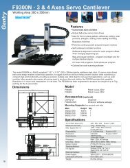
4. APPENDIX D : MACHINE DIMENSIONS ............................................................................................ 179<br />
4.1. F9300N ............................................................................................................................................................... 179<br />
4.2. F9304N ............................................................................................................................................................... 180<br />
4.3. F9600N ............................................................................................................................................................... 181<br />
4.4. F9604N ............................................................................................................................................................... 182<br />
4.5. F9800N ............................................................................................................................................................... 183<br />
4.6. F9804N ............................................................................................................................................................... 184<br />
4.7. F2004N ............................................................................................................................................................... 185<br />
5. APPENDIX E : TABLE DIMENSIONS ................................................................................................. 186<br />
5.1. F9300N/F9304N ................................................................................................................................................. 186<br />
5.2. F9600N/F9604N ................................................................................................................................................. 187<br />
5.3. F9800N/F9804N ................................................................................................................................................. 188<br />
6. APPENDIX F: COORDINATES (AXES) OF ROBOTS ............................................................................. 189<br />
6.1. Manipulator of <strong>F9000N</strong> Series ........................................................................................................................... 189<br />
6.2. Manipulator of F2004N ...................................................................................................................................... 190<br />
6.2.1. Joint Coordinates ........................................................................................................................................... 190<br />
6.2.2. Cartesian Coordinates ................................................................................................................................... 191<br />
- Page 6 -<br />
© 2010 <strong>Fisnar</strong> Inc.
<strong>F9000N</strong> & F2004N Series Operating <strong>Manual</strong><br />
Section 1 : Safety Rev. C- Oct. 11<br />
Section 1:<br />
Safety<br />
- Page 7 -<br />
© 2010 <strong>Fisnar</strong> Inc.
<strong>F9000N</strong> & F2004N Series Operating <strong>Manual</strong><br />
Section 1 : Safety Rev. C- Oct. 11<br />
<strong>F9000N</strong> Gantry and SCARA F2004N robots use the same hardware controller, programming<br />
software and teach pendant. Therefore, the instructions and programming information are<br />
presented in this Operating <strong>Manual</strong> for both of them.<br />
1. CE Certification Requirements<br />
1. In order to meet the safety requirements of the CE directives (applicable in the countries<br />
of European Union) the robots must be placed in an enclosure which can be supplied by<br />
the <strong>Fisnar</strong> Inc. distributors.<br />
2. The enclosure must prevent the access to the moving parts except through the<br />
enclosure door.<br />
3. The enclosure door switch must be connected to the door switch connector on the robot<br />
I/O cable.<br />
2. Safety Rules<br />
1. In order to use a robot in safety conditions, the user should prepare the safety work<br />
regulations under the careful consideration of line layout and side-line establishments<br />
where the robot is installed, and the operator must keep strictly to the safety work<br />
regulations to prevent accidents. Also, standard operation procedure about the robot<br />
must be written-up for safety, and appropriate measures for safety operation must be<br />
taken, such as safety training of the operators.<br />
2. Teaching operation and maintenance procedure of the robot should be set according to<br />
the standards of the Industrial Safety and Health Law and Industrial Safety Regulations.<br />
3. The user should prepare the safety operation regulations of the overall system and abide<br />
by them.<br />
4. In order to secure the robot‟s safety, please observe the general provisions related to the<br />
safety operation of an industrial robot.<br />
5. Prepare a safety management system, such as appointing operators responsible for the<br />
safe operation of robot or deciding on safety supervisors, and give them thorough safety<br />
training.<br />
- Page 8 -<br />
© 2010 <strong>Fisnar</strong> Inc.
<strong>F9000N</strong> & F2004N Series Operating <strong>Manual</strong><br />
Section 1 : Safety Rev. C- Oct. 11<br />
3. General Conditions for Safety<br />
1. Please use robot within the standard requirements (such as payload, speed, operational<br />
range, user environment) as stated in the specification. Make sure specifically that the<br />
single phase is not over AC 230 V / 15A before turning the power on.<br />
2. Make sure the operator has read the operation manual and other materials thoroughly,<br />
so that all problems can be solved, thus minimizing damage during operation.<br />
3. Do not attach or detach the power cord while the power switch of the controller is turned<br />
ON.<br />
4. Do not drop the teach pendant.<br />
5. Install the robot firmly so that it will not be shaken.<br />
6. Install a safety fence around the robot‟s working area for a safe work environment.<br />
7. Check electrical connections before turning on the electrical power of the controller. The<br />
machine may not work properly due to incorrect connection of electrical wires.<br />
8. Install FG (Frame Ground) in order to prevent electric shocks.<br />
4. Safety During Operation<br />
1. To start operation of the robot, turn on the power switch of the robot controller device.<br />
Please read the following conditions for safety during operation.<br />
2. Before starting the operation, make sure that there is no person or obstacle in the robot‟s<br />
working area.<br />
3. Be ready to push the emergency stop switch if the robot does not function normally.<br />
4. Before starting a repetitive operation, make sure that nobody and no obstacle is in the<br />
robot‟s working area enclosed by the safety fence.<br />
5. When several people are working together simultaneously, check for mutual safety,<br />
especially during the power is ON/OFF and during the manual operation.<br />
6. During maintenance and inspection of the robot, pull out the power plug of the controller.<br />
- Page 9 -<br />
© 2010 <strong>Fisnar</strong> Inc.
<strong>F9000N</strong> & F2004N Series Operating <strong>Manual</strong><br />
Section 2 : System Installation Rev. C- Oct. 11<br />
Section 2:<br />
System Installation<br />
- Page 10 -<br />
© 2010 <strong>Fisnar</strong> Inc.
Axis Control<br />
General Condition<br />
<strong>F9000N</strong> & F2004N Series Operating <strong>Manual</strong><br />
Section 2 : System Installation Rev. C- Oct. 11<br />
1. Controller<br />
1.1. Controller Specifications<br />
Item Type Specification<br />
Number of Control axes<br />
Control Method<br />
Positioning Unit<br />
Motion Method<br />
Control Interpolation<br />
Speed 1 ~ 100%<br />
Encoder Type<br />
Position Precision Degree<br />
Size<br />
Weight<br />
Max. Power Capacity<br />
Operation Method<br />
Program Volume<br />
Min. 1 axis, Max. 4 axes<br />
AC Full Digital Servo<br />
Cartesian Coordinates: mm<br />
Axis Coordinates : Degree (Deg)<br />
PTP motion (Joint interpolation),<br />
CP motion, linear motion<br />
Linear interpolation,<br />
circular interpolation<br />
Incremental (9 wires) / Absolute Type usable<br />
(Tamakawa Motor Type)<br />
Within ± 1/4 Encoder Pulse<br />
368 mm x 302 mm x 140 mm<br />
Max 10kg<br />
4 axes Total 2.4 kw<br />
Teach Pendant / Front Panel<br />
3,000 Steps / Program<br />
1,000 Steps x 20 programs<br />
External Input/ Output General 32/32 System 24/6<br />
External Communication<br />
RS-232C<br />
Input Power Single Phase AC 220V 50/60Hz, ±10~15%<br />
Running Temperature and<br />
Humidity<br />
Components<br />
0 ~ 45 Degree C; 20 ~ 80%RH<br />
Controller, Connection cables, Teach Pendant,<br />
User I/O Cable, System I/O Cable,<br />
Power Cable, Dispenser cable, I/O Port<br />
Connector, External Control Connector,<br />
Enclosure (for units delivered to E.U. countries<br />
– not included), Spacers (4-axis robots only)<br />
- Page 11 -<br />
© 2010 <strong>Fisnar</strong> Inc.
Abnormality<br />
<strong>F9000N</strong> & F2004N Series Operating <strong>Manual</strong><br />
Section 2 : System Installation Rev. C- Oct. 11<br />
Abnormalities<br />
Over Current, Over Heat, Following Error,<br />
Encoder error, Board malfunction,<br />
Over Speed, Position deviation abnormality<br />
Brake error, etc.<br />
1.2. Controller Structure<br />
1. Controller<br />
Main Board<br />
2. Teach Pendant<br />
Servo AMP<br />
Servo Board<br />
3. Connection<br />
Cable<br />
Machine<br />
User I/O Board<br />
4. User I/O Cable<br />
System I/O Board<br />
5. System I/O Cable<br />
Power Supply Power Cable AC 220 V Power<br />
1. Controller : Consists of different types of boards and AMP, as shown<br />
above.<br />
2. Teach Pendant : Creates a work program and changes the configurations<br />
of the system.<br />
3. Connection Cable : Connects each channel of the controller and each axis of<br />
the manipulator.<br />
4. User I/O Cable : Connects the user I/O board and other equipment.<br />
5. System I/O Cable : Connects the system I/O board and other equipment.<br />
According to the user‟s needs, the specifications of the Controller or the structure of the<br />
machine can be changed.<br />
The aspects and functions of each part of the Controller are as follows:<br />
- Page 12 -<br />
© 2010 <strong>Fisnar</strong> Inc.
<strong>F9000N</strong> & F2004N Series Operating <strong>Manual</strong><br />
Section 2 : System Installation Rev. C- Oct. 11<br />
1.3. Front View<br />
1. Ventilation Openings<br />
6. Front Panel<br />
2. Emergency Button 3. Teach<br />
Pendant Port<br />
4. Host Port 5. Power<br />
Switch<br />
1. Ventilation openings: Allow the entrance of cold air into the unit to cool the inner heat<br />
produced by the controller during operation. Do not block these openings.<br />
2. Emergency Stop Button: Used when the controller is needed to be stopped<br />
immediately.<br />
3. Teach pendant (T-Box) port: Used to connect the Teach Pendant. Be careful not to<br />
connect the HOST cable.<br />
4. Host port (for RS-232C communication): Used for MMI Serial communication.<br />
5. Power switch: Used to turn on or off the power of the controller. (The light comes on<br />
when the power is ON.)<br />
6. Front Panel is used to operate the controller without a teach pendant.<br />
- Page 13 -<br />
© 2010 <strong>Fisnar</strong> Inc.
<strong>F9000N</strong> & F2004N Series Operating <strong>Manual</strong><br />
Section 2 : System Installation Rev. C- Oct. 11<br />
LCD Screen<br />
LEDs panel<br />
Front Function Keys<br />
<br />
LCD Screen is a 2 line x 16 letter screen and indicates the current state and the program<br />
being operated or selected, as well as the current step.<br />
<br />
LEDs Panel shows the current status.<br />
READY LED : Light is turned on when the robot is ready to start.<br />
RUN LED : Light is turned on while the robot is operating.<br />
ORG LED<br />
ERR LED<br />
: Light is turned on after an origin-searching operation is<br />
performed.<br />
: Light is turned on when an error occurs during operation.<br />
- Page 14 -<br />
© 2010 <strong>Fisnar</strong> Inc.
<strong>F9000N</strong> & F2004N Series Operating <strong>Manual</strong><br />
Section 2 : System Installation Rev. C- Oct. 11<br />
<br />
Front Panel keys are used to choose and operate program.<br />
KEY<br />
◄<br />
Description<br />
This key is used for selecting a Program. When selecting a Program,<br />
press this key to increase the program number by ten<br />
►<br />
This key is used for selecting a Program. When selecting a Program, press this key<br />
to increase the program number one by one.<br />
MODE<br />
This key is used to change the controller to Teach Mode or Run Mode.<br />
RESET<br />
This key is used to reset the error caused.<br />
ORG<br />
This key is used to perform an origin-searching operation<br />
(Go to position of the origin).<br />
START<br />
This key is used to start program running.<br />
STOP<br />
This key is used to stop program running.<br />
- Page 15 -<br />
© 2010 <strong>Fisnar</strong> Inc.
<strong>F9000N</strong> & F2004N Series Operating <strong>Manual</strong><br />
Section 2 : System Installation Rev. C- Oct. 11<br />
1.4. Rear View<br />
1<br />
2 3 4 5 1<br />
6 7 8<br />
9 10 11 8 7<br />
1. Servo Board controls the Servo AMP.<br />
2. Main Board regulates the System‟s control.<br />
3. User I/O Board controls Input or Output and a user can use them <strong>fr</strong>eely. 32 contacts for<br />
the input and 32 contacts for the output are available.<br />
4. SMPS supplies electric power to the controller.<br />
5. System I/O Board is used only to control the system. 24 contacts for the system input<br />
and 6 contacts for the system output are available.<br />
6. AC Inlet is used to input the power, AC 220V.<br />
7. Motor Power Connector is used to connect motors of the manipulator with connecting<br />
cables, supplying high voltage to control the motor.<br />
8. Encoder Connector is used to connect the encoder of the motor with the connecting<br />
cables, allowing the current value of the encoder to be read.<br />
9. Input Connector of User I/O board is used to connect with an external device. This is<br />
only for input <strong>fr</strong>om the external device<br />
10. Output Connector of User I/O board is used to connect with an external device. This<br />
is only for the output to the external device.<br />
11. System I/O Connector is used to connect with an external device or with the External<br />
Control Connector. This is input or output for the system only.<br />
- Page 16 -<br />
© 2010 <strong>Fisnar</strong> Inc.
<strong>F9000N</strong> & F2004N Series Operating <strong>Manual</strong><br />
Section 2 : System Installation Rev. C- Oct. 11<br />
1.5. Connection Cable<br />
This cable is used to connect the machine and the channels of the controller.<br />
This cable consists of two outlets - encoder connector and power connector – on the<br />
controller side, while it has one outlet on the machine side.<br />
Power connector<br />
Manipulator connector<br />
Encoder connector<br />
For proper connection, please refer to Appendix C: Equipment (machine) Connection.<br />
1.6. User I/O Cable<br />
This cable is used to connect the user input/output of the external device and the<br />
input/output port of the User I/O board. There are independent connectors for the user Input<br />
and the user Output. Each connector has 32/32 contacts.<br />
For more details, please refer to Appendix A.<br />
1.7. System I/O Cable<br />
This cable is used to connect the input/output ports of the external device and the<br />
input/output ports of the system I/O board. The input and output are connected with only<br />
one connector. The system input has 24 contacts and the output has 6 contacts.<br />
For more details, please refer to Appendix B.<br />
- Page 17 -<br />
© 2010 <strong>Fisnar</strong> Inc.
<strong>F9000N</strong> & F2004N Series Operating <strong>Manual</strong><br />
Section 2 : System Installation Rev. C- Oct. 11<br />
2. Installation of the Product<br />
2.1. Initial Considerations.<br />
1. Install the product in a well-ventilated area to avoid overheating.<br />
2. Prevent vibration of the unit. Too much vibration can do considerable damage to the<br />
controller.<br />
3. Keep moisture level low. Avoid direct contact between water and the unit.<br />
4. Protect unit against atmospheric agents.<br />
5. Make all connected cables <strong>fr</strong>ee <strong>fr</strong>om vibration.<br />
6. Please install FG (Frame Ground).<br />
7. Make sure that the motor specification indicated on the backside of the controller and<br />
the one in the machine are matched.<br />
8. Make sure that the power voltage is AC 220V.<br />
9. Connect all cables appropriately and tie them up to prevent disconnection.<br />
Note: To be seen Appendix F for the coordinates (axes) of the robots.<br />
- Page 18 -<br />
© 2010 <strong>Fisnar</strong> Inc.
<strong>F9000N</strong> & F2004N Series Operating <strong>Manual</strong><br />
Section 2 : System Installation Rev. C- Oct. 11<br />
2.2. Connecting the Controller to the Manipulator<br />
1. Connect the cables between the controller and the manipulator. Depending if the<br />
manipulator has 3 or 4 axes, there will be 3 or 4 sets of cables respectively. Each set of<br />
cables is labeled with the corresponding connections: CH1-ENC1 (for X), CH2-ENC2 (for<br />
Y), CH3-ENC3 (for Z), and CH4-ENC4 (for R). Each channel in the back of the controller<br />
is also labeled with the corresponding connections: CH1-ENC1 (for X), CH2-ENC2 (for<br />
Y), CH3-ENC3 (for Z), and CH4-ENC4 (for R).<br />
X<br />
Z<br />
In each set of cables, the end that connects to the<br />
controller has two connectors.<br />
<br />
Power Connector<br />
Encoder Connector<br />
In the back of the controller, for each axis there are two outlets<br />
<br />
Power outlet<br />
Y<br />
Encoder outlet<br />
Connect as follows, matching the connecting symbols labeled on the cables (CH1-ENC1,<br />
CH2-ENC2, CH3-ENC3, CH4-ENC4) with the corresponding connecting symbols on the<br />
controller.<br />
R<br />
W<br />
The power connector is connected to the power outlet.<br />
- Page 19 -<br />
© 2010 <strong>Fisnar</strong> Inc.
<strong>F9000N</strong> & F2004N Series Operating <strong>Manual</strong><br />
Section 2 : System Installation Rev. C- Oct. 11<br />
The encoder connector is connected to the encoder outlet.<br />
The manipulator connector is connected to the connecting outlet.<br />
When you connect each cable and the External Control Connector, be sure to tighten the<br />
screws so that to avoid any disconnection.<br />
2. Connect the system input/output cable, or the External Control Connector.<br />
3. Connect the user input/output cable (if necessary)<br />
4. Connect the Teach pendant cable to the Teach Pendant (T-Box) outlet on the controller.<br />
5. Connect the power cable. The power should be single-phase AC 220V.<br />
- Page 20 -<br />
© 2010 <strong>Fisnar</strong> Inc.
<strong>F9000N</strong> & F2004N Series Operating <strong>Manual</strong><br />
Section 2 : System Installation Rev. C- Oct. 11<br />
2.3. Turning ON the Controller for the first time.<br />
Check that all the cables have been properly connected, and then turn ON the controller.<br />
Usually, the controller is preconfigured with the specific parameters for the manipulator. If that is<br />
the case, the Teach Pendant will display the following sequence of messages.<br />
DATA LOADING………<br />
PLEASE WAIT<br />
----------------------<br />
Press Home Key<br />
To Find Origin<br />
-----------------------<br />
If the controller has not been preconfigured with the parameters for your manipulator, the Teach<br />
Pendant will display the following screen.<br />
Select Robot Type<br />
TYPE [ F9332N ]<br />
Change: UP/DOWN<br />
Save: ENT Skip: ESC<br />
<br />
<br />
Using the ▲▼ keys on the Teach Pendant, select your type of the manipulator <strong>fr</strong>om the list.<br />
Your manipulator‟s type can be read on the back side of the manipulator.<br />
Press the ENT key on the Teach Pendant. The Teach Pendant will display the following<br />
sequence of messages:<br />
DATA LOADING………<br />
PLEASE WAIT<br />
----------------------<br />
Press Home Key<br />
To Find Origin<br />
---------------------------<br />
- Page 21 -<br />
© 2010 <strong>Fisnar</strong> Inc.
<strong>F9000N</strong> & F2004N Series Operating <strong>Manual</strong><br />
Section 3 : Teaching Overview Rev. C- Oct. 11<br />
Section 3:<br />
Teaching Overview<br />
- Page 22 -<br />
© 2010 <strong>Fisnar</strong> Inc.
<strong>F9000N</strong> & F2004N Series Operating <strong>Manual</strong><br />
Section 3 : Teaching Overview Rev. C- Oct. 11<br />
1. Teaching Overview<br />
A program consists of a series of instructions stored in the main unit memory. Each instruction<br />
is stored in a numbered memory address. A memory address may record a point location, with<br />
an X, Y, Z and R (for 4-axis robots) value and point type or it may store an instruction which<br />
sets a parameter, such as a dispensing time or a line speed.<br />
When the program is run, the robot will step through each memory address in sequence and<br />
execute the instruction found there. If the memory address contains a point location, the robot<br />
will move the X, Y and Z axes to that location and also will execute the rotation corresponding<br />
to the value of the R in that point. Depending on the type of point registered at that location, the<br />
robot may also perform other functions, such as turn the dispenser on or off.<br />
The most commonly used point types are: Dispense Dot, Line Start, Line Passing, Arc Point,<br />
and Line End.<br />
To program the robot to dispense a „dot‟ of material, the dispensing tip must be jogged to the<br />
desired XYZ location (and in the desired R position of the tip), then that location is registered as<br />
a DISPENSE DOT type by pressing the appropriate key on the Teach Pendant.<br />
To program<br />
the robot to dispense a<br />
bead of material along a linear path, the XYZ location (and R position of the tip) of the start of<br />
the line is registered as a LINE START point. The locations where the tip changes direction<br />
(and position) are registered as LINE PASSING points. The end of the line is registered as a<br />
LINE END point:<br />
- Page 23 -<br />
© 2010 <strong>Fisnar</strong> Inc.
<strong>F9000N</strong> & F2004N Series Operating <strong>Manual</strong><br />
Section 3 : Teaching Overview Rev. C- Oct. 11<br />
To dispense a bead of material in an arc, the XYZ location (and R position of the tip) of the start<br />
of the line is registered as a LINE START point. The high point of the arc is registered as an<br />
ARC Point. The end of the arc is registered as a LINE END point:<br />
Lines and arcs can also be combined to dispense a bead of material along a complex path:<br />
Once the required point locations for your program have been taught, the teach pendant is no<br />
longer required. The unit can be switched to RUN mode and operated using the buttons and<br />
switches on the main unit control panel.<br />
- Page 24 -<br />
© 2010 <strong>Fisnar</strong> Inc.
<strong>F9000N</strong> & F2004N Series Operating <strong>Manual</strong><br />
Section 3 : Teaching Overview Rev. C- Oct. 11<br />
2. Using the Teach Pendant<br />
The teach pendant enables the user to jog robot to input program data.<br />
If Shift/Char is pressed,<br />
released, and next the<br />
Speed key is pressed,<br />
Speed is executed.<br />
When entering<br />
alphabetical Characters,<br />
if Shift/Char is pressed,<br />
released, this key is „M‟.<br />
When entering<br />
numbers, this key is 7<br />
2.1. Key Selection<br />
There are several functions assigned to most keys on the teach pendant. When such a key is<br />
pressed alone, the function shown in the white colored area on the key is executed. The<br />
functions MENU 1, MENU 2, Setup, and Condition are all the default key functions that are<br />
executed when their keys are pressed alone.<br />
To access the function shown at the top of a blue key, press and release the Shift /Char key<br />
first, then press the desired key. To select a function shown in the black area of a key, like – for<br />
example - the Speed function, press and release Shift/Char, then press the Speed key.<br />
When a number is required, the teach pendant will automatically switch to numeric entry mode.<br />
The number represented by each key is shown in the lower left corner of the key.<br />
When an Alphabetical character is required, press the Shift/Char key first. The character<br />
represented by each key is shown in the lower side or in the lower right side of the key.<br />
- Page 25 -<br />
© 2010 <strong>Fisnar</strong> Inc.
<strong>F9000N</strong> & F2004N Series Operating <strong>Manual</strong><br />
Section 3 : Teaching Overview Rev. C- Oct. 11<br />
2.2. Key Assignments<br />
Menu Keys<br />
ENT<br />
Opens the Point registration menu.<br />
F1<br />
Setup<br />
F2<br />
Cond<br />
Inch<br />
Menu1<br />
Mode<br />
Menu2<br />
Opens the Setup menu.<br />
Opens the Condition Menu.<br />
Opens Menu # 1. It is also used for the Inch Jog Mode by<br />
pressing the Shift/Char key first.<br />
Opens Menu # 2. It is also used for the Mode Change by<br />
pressing the Shift/Char key first.<br />
Jog Keys<br />
- 1X<br />
S<br />
+ 1X<br />
X<br />
- 2Y<br />
T<br />
+ 2Y<br />
Y<br />
- 3Z<br />
U<br />
+ 3Z<br />
Z<br />
Jogs the X axis in the forward direction.<br />
Jogs the X axis in the backward direction.<br />
Jogs the Y axis in the left direction.<br />
Jogs the Y axis in the right direction.<br />
Jogs the Z axis UP.<br />
Jogs the Z axis DOWN.<br />
- 4W<br />
V<br />
+ 4W<br />
W<br />
Jogs the Rotation axis.<br />
- Page 26 -<br />
© 2010 <strong>Fisnar</strong> Inc.
<strong>F9000N</strong> & F2004N Series Operating <strong>Manual</strong><br />
Section 3 : Teaching Overview Rev. C- Oct. 11<br />
◄<br />
SPD -<br />
►<br />
SPD+<br />
Changes jog speed. Right arrow button is used for increasing<br />
jog speed. Left arrow button is used for decreasing jog speed.<br />
Navigation Keys<br />
▼<br />
+1<br />
▲<br />
-1<br />
PgDn<br />
+10<br />
PgUp<br />
-10<br />
Moves forward (1) memory address.<br />
Moves backward (1) memory address.<br />
Moves forward (10) memory addresses.<br />
Moves backward (10) memory addresses.<br />
2.3. Navigation Menu<br />
F1<br />
F2<br />
Inch<br />
Pressing any of the keys shown on the right will open the<br />
corresponding menu.<br />
Setup Cond Menu1<br />
Mode<br />
ENT<br />
Menu2<br />
Once the menu is open, use the up and down arrows to<br />
move through the items on the menu.<br />
▲<br />
-1<br />
▼<br />
+1<br />
Use the Page Up and Page Down keys to change to the<br />
next page or previous page of the menu.<br />
PgUp<br />
-10<br />
SPD -<br />
PgDn<br />
+10<br />
SPD +<br />
Press ENTER to select the current item.<br />
ENT<br />
- Page 27 -<br />
© 2010 <strong>Fisnar</strong> Inc.
<strong>F9000N</strong> & F2004N Series Operating <strong>Manual</strong><br />
Section 3 : Teaching Overview Rev. C- Oct. 11<br />
2.4. Jogging<br />
The tip is jogged by pressing the jog buttons after the<br />
Servo button is pressed.<br />
Jog speed has three velocity levels: low, middle and high.<br />
If the right arrow button is pressed, the jog speed<br />
changes to a faster level.<br />
If the left arrow button is pressed, the jog speed changes<br />
to a slower level.<br />
The value of the jog speed (at the velocity level: high) can<br />
be set using the function Jog Speed (Menu 1). (See<br />
Section 6: 4.6 Jog Speed).<br />
The Speed led display on the Teach Pendant shows the<br />
velocity level: high, middle or low.<br />
Servo<br />
A<br />
- 1X<br />
S<br />
- 2Y<br />
T<br />
- 3Z<br />
U<br />
- 4W<br />
V<br />
◄<br />
SPD -<br />
+ 1X<br />
X<br />
+ 2Y<br />
Y<br />
+ 3Z<br />
Z<br />
+ 4W<br />
W<br />
►<br />
SPD +<br />
Changes to Inch Jog Mode. Shift +<br />
/Char<br />
Inch<br />
Menu1<br />
2.5. Data Entry<br />
The Teach Pendant is used also to enter numeric data. If a numeric value is required, the Teach<br />
Pendant will automatically switch to numeric mode. Use the keys 0 – 9, (.), and (-) to enter the<br />
values.<br />
- Page 28 -<br />
© 2010 <strong>Fisnar</strong> Inc.
<strong>F9000N</strong> & F2004N Series Operating <strong>Manual</strong><br />
Section 3 : Teaching Overview Rev. C- Oct. 11<br />
2.6. LED Panel<br />
This indicates the current system status and speed.<br />
<br />
SERVO LED : The light is turned on when the robot is run or ready to move after<br />
Servo is turned ON.<br />
ORG LED : The light is turned on after the function of Origin is performed.<br />
CHAR LED : The light is turned on when the CHAR key is pressed.<br />
ERR LED : The light is turned on when the Error occurs in the robot.<br />
INCH LED : The light is turned on when the current mode is Inch Mode.<br />
LOW LED : The light is turned on when the current jog speed is low.<br />
MED LED : The light is turned on when the current jog speed is medium.<br />
HIGH LED : The light is turned on when the current jog speed is high.<br />
3. Teach Box Key Assignments<br />
Key<br />
Function<br />
F1<br />
Setup<br />
F2<br />
Cond<br />
Inch<br />
Menu1<br />
Mode<br />
Menu2<br />
Servo<br />
A<br />
Brake<br />
B<br />
Jump<br />
C<br />
Opens Setup Menu.<br />
Opens Condition Menu.<br />
Opens Menu #1.<br />
With Shift/Char key, it is used for Inch Jog Mode.<br />
Opens Menu #2.<br />
With Shift/Char key, it is used for Mode Change.<br />
Turns the servo motor On/Off.<br />
Releases or locks the Brake.<br />
Jumps to a specified memory address.<br />
- Page 29 -<br />
© 2010 <strong>Fisnar</strong> Inc.
<strong>F9000N</strong> & F2004N Series Operating <strong>Manual</strong><br />
Section 3 : Teaching Overview Rev. C- Oct. 11<br />
Key<br />
Function<br />
STOP<br />
Stops program running.<br />
Prog<br />
Num<br />
Move<br />
D<br />
Ins<br />
E<br />
Del<br />
F<br />
Shift<br />
/Char<br />
Goes to another program.<br />
Moves the tip to the point location currently in the display.<br />
Inserts a memory address before the current address.<br />
Deletes the current memory address.<br />
Changes to character mode or shift mode.<br />
RESET<br />
Resets current error.<br />
ESC<br />
Changes <strong>fr</strong>om Point List display mode to single point<br />
display when teaching point data. If pressed once, clears<br />
the current numeric value.<br />
◄<br />
SPD-<br />
►<br />
SPD+<br />
Jog speed has three velocity levels: low, middle and high.<br />
If the right arrow button is pressed, jog speed is changed<br />
to a faster level. If the left arrow button is pressed, jog<br />
speed is changed to a slower level. The Speed led display<br />
on the Teach Pendant shows the velocity level.<br />
PgUp<br />
-10<br />
▲<br />
-1<br />
PgDn<br />
+10<br />
▼<br />
+1<br />
Moves backward (10) memory addresses.<br />
Moves backward (1) memory address.<br />
Moves forward (10) memory addresses.<br />
Moves forward (1) memory address.<br />
- Page 30 -<br />
© 2010 <strong>Fisnar</strong> Inc.
<strong>F9000N</strong> & F2004N Series Operating <strong>Manual</strong><br />
Section 3 : Teaching Overview Rev. C- Oct. 11<br />
Key<br />
ENT<br />
Function<br />
Confirms data entries. Also opens the Point registration<br />
menu.<br />
Shift<br />
/Char<br />
Shift<br />
/Char<br />
Shift<br />
/Char<br />
Shift<br />
/Char<br />
Shift<br />
/Char<br />
Shift<br />
/Char<br />
Shift<br />
/Char<br />
Shift<br />
/Char<br />
Shift<br />
/Char<br />
Dot<br />
1 / G<br />
Start<br />
2 / H<br />
Pass<br />
3 / I<br />
End<br />
4 / J<br />
Arc<br />
5 / K<br />
End Pr<br />
6 / L<br />
Speed<br />
7 / M<br />
Setup<br />
8 / N<br />
Setup<br />
9 / O<br />
Shortcut for registering a Dispense Dot.<br />
Shortcut for registering a Line Start point.<br />
Shortcut for registering a Line Passing point.<br />
Shortcut for registering a Line End point.<br />
Shortcut for registering an Arc Point.<br />
Shortcut for registering the End Program command.<br />
Shortcut for registering Line Speed.<br />
Shortcut for registering a Point Dispense Setup.<br />
Shortcut for registering a Line Dispense Setup.<br />
First<br />
0 / P<br />
End<br />
. / Q<br />
Changes the display to memory address number 0.<br />
Changes the display to the last used memory address in<br />
the program.<br />
Shift<br />
/Char<br />
Mode<br />
Menu2<br />
Changes to Run / Teach Mode.<br />
Home<br />
- / R<br />
„Home‟ the robot. Initializes all axes and moves to (0,0,0,0).<br />
- Page 31 -<br />
© 2010 <strong>Fisnar</strong> Inc.
<strong>F9000N</strong> & F2004N Series Operating <strong>Manual</strong><br />
Section 3 : Teaching Overview Rev. C- Oct. 11<br />
4. Point Type Functions Summary<br />
4.1. Point Menu<br />
Below is a list of Point type functions that are found under the Enter key (Point menu):<br />
Function<br />
Dispense Dot<br />
Line Start<br />
Line Passing<br />
Line End<br />
Arc Point<br />
Circle<br />
Center<br />
Dummy<br />
End Program<br />
Description<br />
Registers the current XYZ location (and R position of tip) as<br />
a Dispense point for dot dispensing.<br />
Registers the current XYZ location (and R position of tip) as<br />
a Line Start point for line dispensing.<br />
Registers the current XYZ location (and R position of tip) as<br />
a Line Passing point. This is a location on the line where the<br />
tip changes direction, such as at the corner of a rectangle.<br />
Registers the current XYZ location (and R position of tip) as<br />
a Line End point.<br />
Registers the current XYZ location (and R position of tip) as<br />
an Arc Point. Arc Points are used to dispense material in an<br />
arc or circle.<br />
Registers the current XYZ location (and R position of tip) as<br />
a Circle point. Circle points are used to dispense material in<br />
a circle.<br />
Registers the current XYZ location (and R position of tip) as<br />
a center point of circle. Center points are used to dispense<br />
material in a circle.<br />
Registers the current XYZ location (and R position of tip) as<br />
a Dummy point. The tip will simply pass through this point.<br />
This is useful for avoiding obstacles on the work piece.<br />
Registers the current memory address as the end of the<br />
program.<br />
- Page 32 -<br />
© 2010 <strong>Fisnar</strong> Inc.
<strong>F9000N</strong> & F2004N Series Operating <strong>Manual</strong><br />
Section 3 : Teaching Overview Rev. C- Oct. 11<br />
Function<br />
Dispense ON / OFF<br />
Home Point<br />
Wait Point<br />
Stop Point<br />
Brush Area<br />
If<br />
Output<br />
Input<br />
Pulse<br />
Point<br />
Description<br />
Registers an instruction which turns the dispenser on or off<br />
at the current memory address.<br />
Sets robot to home position.<br />
Registers a Wait Point at the current X, Y, Z location (and R<br />
position of tip). When executed, the tip will move to that<br />
location and wait for the specified period of time.<br />
Registers a Stop Point at the current X, Y, Z location (and R<br />
position of tip). When executed, the tip will move to that<br />
location and wait until the start button is pressed.<br />
Causes the tip to „paint‟ the defined area. The painted area<br />
can be in the form of a rectangle or a circle / spiral.<br />
Registers an instruction that either sets the value of an<br />
output signal or checks the status of an input signal.<br />
Registers an instruction that sets the value of an output<br />
signal.<br />
Registers an instruction that waits for an input signal.<br />
Registers an instruction that sets the value of an output<br />
signal and Output Time.<br />
Sets point variable P0 ~ P99 by saving current position or<br />
input numerical data.<br />
- Page 33 -<br />
© 2010 <strong>Fisnar</strong> Inc.
<strong>F9000N</strong> & F2004N Series Operating <strong>Manual</strong><br />
Section 3 : Teaching Overview Rev. C- Oct. 11<br />
4.2. Setup Menu<br />
Below is a list of functions that are found under the Setup key (Setup menu):<br />
Function<br />
Line Speed<br />
Line Dis. Setup<br />
Point Dis. Setup<br />
Dispense End Setup<br />
Z Clearance<br />
XY Move Speed<br />
Z Move Speed<br />
Description<br />
Registers the LINE SPEED used for all lines <strong>fr</strong>om the<br />
current memory address forward until another Line<br />
Speed instruction is found.<br />
Registers the LINE DISPENSE SETUP values which set<br />
dispensing wait time at the start of lines („head‟ time)<br />
waiting time at the end of lines („tail‟ time), and dispense<br />
off length („head‟ length and „tail‟ length).Output<br />
(„Output‟) The registered values will be used <strong>fr</strong>om the<br />
current memory address forward until another Line<br />
Dispense Setup instruction is found.<br />
Registers POINT DISPENSE SETUP values which set<br />
dispensing time and waiting time at the end of<br />
dispensing („tail‟ time) for dots. Output („Output‟), The<br />
registered values will be used <strong>fr</strong>om the current memory<br />
address forward until another POINT DISPENSE<br />
SETUP instruction is found.<br />
Registers the height and speed the tip should rise at the<br />
end of dispensing. The registered values will be used<br />
<strong>fr</strong>om the current memory address forward until another<br />
DISPENSE END SETUP instruction is found.<br />
Registers the additional distance the tip should rise,<br />
beyond the height set in Dispense End Setup, to allow<br />
obstacles to be cleared as the tip moves <strong>fr</strong>om one figure<br />
to another. Values will be used until another Z Clearance<br />
instruction is found.<br />
Sets the movement speed of the X and Y axes when<br />
moving <strong>fr</strong>om one figure to another in the program.<br />
Sets the movement speed of the Z axis when moving<br />
<strong>fr</strong>om one figure to another in the program.<br />
- Page 34 -<br />
© 2010 <strong>Fisnar</strong> Inc.
<strong>F9000N</strong> & F2004N Series Operating <strong>Manual</strong><br />
Section 3 : Teaching Overview Rev. C- Oct. 11<br />
Function<br />
Home Position<br />
Retract<br />
Auto Purge<br />
Description<br />
Changes the position the robot moves to at the end of a<br />
program cycle.<br />
Registers Retract values at the current XYZ location.<br />
Retract causes the tip to move up and back over the<br />
dispensed bead after line dispensing.<br />
Registers Wait time and Purge time, for purging the<br />
system at the end of a program.<br />
Adjust Point #1<br />
Adjust Point #2<br />
CCD Shot<br />
Relocate<br />
Round<br />
Z Lift<br />
Saves current position and steps as a first data for<br />
Relocate Data function. Saves current position to<br />
temporary point #1.<br />
Saves current position and steps as a second data for<br />
Relocate Data function. Saves current position to<br />
temporary point #2.<br />
Used for Vision Application<br />
Used for Vision Application<br />
Sets radius of a line at a Line Passing point.<br />
Select whether lifting Z axis or not, when robot MOVE to<br />
point in TEACHING MODE.<br />
- Page 35 -<br />
© 2010 <strong>Fisnar</strong> Inc.
<strong>F9000N</strong> & F2004N Series Operating <strong>Manual</strong><br />
Section 3 : Teaching Overview Rev. C- Oct. 11<br />
4.3. Condition Menu<br />
Below is a list of functions that are found under the<br />
F2<br />
Cond<br />
key:<br />
Function<br />
Goto Address<br />
Step & Repeat X<br />
Description<br />
Causes the program to jump to the specified memory<br />
address when executed.<br />
Registers an instruction that will re-run a selected group of<br />
memory addresses, stepping by a user-defined distance in<br />
the X or Y axis after each copy. The matrix of parts is defined<br />
by specifying the number of rows, the number of columns,<br />
the X offset and the Y offset.<br />
Step & Repeat X indicates that the robot will give priority to<br />
the X axis, running the parts along the X axis first.<br />
Step & Repeat Y<br />
Registers an instruction that will re-run a selected group of<br />
memory addresses, stepping by a user-defined distance in<br />
the X or Y axis after each copy. The matrix of parts is defined<br />
by specifying the number of rows, the number of columns,<br />
the X offset and the Y offset.<br />
Step & Repeat Y indicates that the robot will give priority to<br />
the Y axis, running the parts along the Y axis first.<br />
Call Subroutine<br />
Call Program<br />
Loop Address<br />
Causes the machine to jump to a specified memory address<br />
and execute the instructions found there. When the end<br />
program instruction is reached, program execution will<br />
continue at address just after the call Subroutine instruction.<br />
Executes the specified program number <strong>fr</strong>om within the<br />
current program. After the called program completes, the<br />
current program will continue execution.<br />
Causes the program to execute a group of memory<br />
addresses a user-specified number of times.<br />
- Page 36 -<br />
© 2010 <strong>Fisnar</strong> Inc.
<strong>F9000N</strong> & F2004N Series Operating <strong>Manual</strong><br />
Section 3 : Teaching Overview Rev. C- Oct. 11<br />
Label<br />
Arm<br />
FixR<br />
Calc<br />
Jmov/ Lmov<br />
IncJ / IncL<br />
XMov<br />
XCopy<br />
Pallet<br />
Offset<br />
Pattern / End Pattern<br />
Sets Label. Label can be used instead of Address Number.<br />
For F2004N Series, it determines the position of the arm.<br />
For <strong>F9000N</strong> Series, it determines the XYZ coordinate or<br />
RYZ coordinate.<br />
Fixes/unfixes the axis rotation while a linear movement is<br />
executed.<br />
Arithmetic Instruction.<br />
Registers current XYZ position or Point variable to Moving<br />
position.<br />
Registers current XYZ position or Point variable as an Offset<br />
position.<br />
While moving, if a sensor signal is turned ON, robot will stop<br />
immediately, and save current position to P98.<br />
N/A<br />
Registers a pallet movement setting.<br />
Set Offset value or point number. Every position after Offset<br />
command will be increased by Offset Value.<br />
It is similar with the Step & Repeat Instruction, but it can<br />
change the Repeat order.<br />
- Page 37 -<br />
© 2010 <strong>Fisnar</strong> Inc.
<strong>F9000N</strong> & F2004N Series Operating <strong>Manual</strong><br />
Section 3 : Teaching Overview Rev. C- Oct. 11<br />
4.4. Menu 1<br />
Below is a list of functions that are found under the Menu 1 key:<br />
Function<br />
Program Name<br />
Z Axis Limit<br />
Initial Output<br />
Cycle Counter<br />
Set Password<br />
Jog Speed<br />
Run Mode<br />
Adjust Position<br />
Parameter<br />
Resume<br />
Origin searching<br />
Hour Meter<br />
PLC File Edit<br />
I/O Monitor<br />
Description<br />
Allows the user to register a name for the current<br />
program number.<br />
Sets the limits between which the Z axis will move<br />
during a program.<br />
Sets the status of the output signals when the machine<br />
is initialized.<br />
Enables or disables the program cycle counter shown in<br />
the display when in run mode.<br />
Sets Password to protect all programs <strong>fr</strong>om unwilling<br />
editing.<br />
Sets the value of the jogging speed, both the linear<br />
speed and the rotation speed (for 4-axis robots).<br />
Determines whether the robot operates in Standalone<br />
mode (default) or Slave mode. Slave mode allows the<br />
robot to be controlled by commands sent over the<br />
RS232 port.<br />
Sets Adjust Position for Adjust Origin.<br />
Sets all parameters about machine and controller.<br />
Determines if a program will restart <strong>fr</strong>om point #0 or the<br />
point at which it was interrupted if a program is stopped<br />
by an emergency stop or the enclosure door switch<br />
open signal.<br />
Executes origin searching, making the robot to go to the<br />
position established as home position.<br />
Shows the working time and running time of the robot.<br />
Edits PLC File.<br />
Views Input/Output status.<br />
- Page 38 -<br />
© 2010 <strong>Fisnar</strong> Inc.
<strong>F9000N</strong> & F2004N Series Operating <strong>Manual</strong><br />
Section 3 : Teaching Overview Rev. C- Oct. 11<br />
Function<br />
Set Variable<br />
Emg Mode<br />
Vision Set<br />
Description<br />
Sets Variable that is used in arithmetic instruction.<br />
Selects SYS EMG mode.<br />
N/A<br />
4.5. Menu 2<br />
Below is a list of functions that are found under the Menu 2 key:<br />
Function<br />
Description<br />
Point Utility<br />
MDI Mode<br />
Numerical Move<br />
Save Temp Point<br />
Retr. Temp Point<br />
Changes Position value of each address by numerical<br />
key input.<br />
Allows the tip to be positioned numerically by entering<br />
numbers for the X, Y, Z and R values.<br />
Saves the current XYZR position in a temporary memory<br />
area numbered 1 – 9.<br />
Retrieves an XYZR position, which was stored with<br />
Save Temp Point.<br />
Group Utility<br />
Group Edit<br />
Expand Step &<br />
Repeat<br />
Relocate Data<br />
Allows a function to be applied to a user-defined group<br />
of memory addresses. Functions include copy, delete,<br />
move, multiply line speed, multiply dispense times, apply<br />
X offset, apply Y offset, apply Z offset.<br />
Expands the memory address locations which would be<br />
performed at a Step & Repeat instruction so individual<br />
memory addresses of the repeated instructions can be<br />
edited.<br />
Allows the position of a program to be corrected using<br />
two reference points. Corrects for X offset, Y offset, Z<br />
offset and angle of rotation.<br />
- Page 39 -<br />
© 2010 <strong>Fisnar</strong> Inc.
<strong>F9000N</strong> & F2004N Series Operating <strong>Manual</strong><br />
Section 3 : Teaching Overview Rev. C- Oct. 11<br />
Function<br />
Adjust Origin<br />
Adjusts origin position.<br />
Description<br />
Program Utility<br />
Copy Program<br />
Delete Program<br />
Auto Offset<br />
Allows programs to be copied.<br />
Allows programs to be deleted.<br />
Adjust position quickly.<br />
Memory Utility<br />
Delete Memory<br />
Clears whole memory.<br />
Note: Certain functions shown on the display are not applicable to these units and consequently<br />
they are marked in the manual as “N/A”.<br />
- Page 40 -<br />
© 2010 <strong>Fisnar</strong> Inc.
<strong>F9000N</strong> & F2004N Series Operating <strong>Manual</strong><br />
Section 4 : Programming Example Rev. C- Oct. 11<br />
Section 4:<br />
Programming Example<br />
- Page 41 -<br />
© 2010 <strong>Fisnar</strong> Inc.
<strong>F9000N</strong> & F2004N Series Operating <strong>Manual</strong><br />
Section 4 : Programming Example Rev. C- Oct. 11<br />
1. Programming Example<br />
To help you become familiar with programming the robot, please follow the instructions below to<br />
create a program that dispenses in the following pattern:<br />
Notes:<br />
We will create the pattern above in the program # 10.<br />
<br />
We will use a line speed of 40 mm/sec for the lines and arcs in the program.<br />
For dots, we will use a dispensing time of 0.50 seconds and a waiting (tail) time of 0.1<br />
seconds after dispensing.<br />
- Page 42 -<br />
© 2010 <strong>Fisnar</strong> Inc.
<strong>F9000N</strong> & F2004N Series Operating <strong>Manual</strong><br />
Section 4 : Programming Example Rev. C- Oct. 11<br />
1 Turn on the controller.<br />
Instruction<br />
2 Select EXIT by pressing the Menu2 key.<br />
3<br />
4<br />
5<br />
Press the Home button. The robot will move to the<br />
home position.<br />
Press the F1/Setup key, then 1 to select Line<br />
Speed (<strong>fr</strong>om page 1/4 of the Setup Menu) to<br />
register a line speed of 40 mm/second at memory<br />
address number 0.<br />
The robot is now waiting for the speed to be<br />
registered. Press 40, then ENTER to register a<br />
speed of 40 mm / second.<br />
Display Shows<br />
PROG:00<br />
AUTO<br />
Press Move Key<br />
Cycle Counter: 0<br />
MODE PLC RESET EXIT<br />
-------------------<br />
Press Home Key<br />
To Find Origin<br />
-------------------<br />
ADDR:0<br />
EMPTY<br />
X:0 Y:0<br />
Z:0 R:0<br />
Line Speed<br />
PROG:10<br />
----------------<br />
Speed:<br />
unit: mm/sec<br />
ADDR:1<br />
EMPTY<br />
PROG:10<br />
- Page 43 -<br />
© 2010 <strong>Fisnar</strong> Inc.
<strong>F9000N</strong> & F2004N Series Operating <strong>Manual</strong><br />
Section 4 : Programming Example Rev. C- Oct. 11<br />
Instruction<br />
Display Shows<br />
The display shows that we are at memory address<br />
1 and that it is empty.<br />
Jog the dispense tip to the first location in the<br />
diagram above (1: Line Start).<br />
6<br />
To jog the X, Y, Z axes and R position of tip, press<br />
the respective Jog keys.<br />
Press the<br />
►<br />
SPD+<br />
key to jog fast. See<br />
ADDR: 1 PROG: 10<br />
X: 0 Y: 0<br />
Z: 0 R: 0<br />
Teaching Overview Section 3:2.4 Jogging for<br />
more information.<br />
Once the tip is at the correct X, Y, Z, R location for<br />
the first point (1: Line Start), press the ENTER<br />
7<br />
key, then 2 (<strong>fr</strong>om page 1/5 of the Point Menu) to<br />
register the location as a Line Start point.<br />
(Note: From now on, the symbols and the values<br />
displayed for the X, Y, Z axes and R position will<br />
not be written in the column “Display Shows” of<br />
ADDR:2<br />
EMPTY<br />
PROG:10<br />
this example).<br />
The display will show that we are at memory<br />
address 2 and it is empty. Jog the tip to the X, Y, Z,<br />
ADDR:3<br />
EMPTY<br />
PROG:10<br />
R location of the second point (2: Line Passing).<br />
8<br />
When the location is correct, press the ENT key,<br />
then 3 (<strong>fr</strong>om page 1/5 of the Point Menu) to<br />
register the location as a Line Passing point.<br />
Now jog the tip to the location of the third point<br />
ADDR:4<br />
PROG:10<br />
9<br />
(3: Arc Point). When the location is correct, press<br />
the ENT key, then 1(<strong>fr</strong>om page 2/5 of the Point<br />
Menu) to register the location as an Arc Point.<br />
EMPTY<br />
- Page 44 -<br />
© 2010 <strong>Fisnar</strong> Inc.
<strong>F9000N</strong> & F2004N Series Operating <strong>Manual</strong><br />
Section 4 : Programming Example Rev. C- Oct. 11<br />
10<br />
11<br />
12<br />
13<br />
14<br />
15<br />
16<br />
Instruction<br />
Jog the tip to the location of the fourth point<br />
(4: Line Passing). When the location is correct,<br />
press the ENT key, then 3 (<strong>fr</strong>om page 1/5 of the<br />
Point Menu) to register the location as a Line<br />
Passing point.<br />
Jog the tip to the location of the fifth point<br />
(5: Line Passing). When the location is correct,<br />
press the ENT key, then 3 (<strong>fr</strong>om page 1/5 of the<br />
Point Menu) to register the location as a Line<br />
Passing point.<br />
Jog the tip to the location of the sixth point<br />
(6: Line Passing). When the location is correct,<br />
press the ENT key, then 3 (<strong>fr</strong>om page 1/5 of the<br />
Point Menu) to register the location as a Line<br />
Passing point.<br />
Jog the tip to the location of the seventh point<br />
(7: Line End). When the location is correct, press<br />
the ENT key, then 4 (<strong>fr</strong>om page 1/5 of the Point<br />
Menu) to register the location as a Line End point.<br />
The line is now complete. The next step is to<br />
register the dispense settings for the dots.<br />
Press the F1/SETUP key, then 3 to register the<br />
Point Dispensing Setup.<br />
Type 0.5 to register a dispensing time of 0.5<br />
seconds, and then press ENT.<br />
Type 0.1 to register a waiting (tail) time after<br />
dispensing of 0.1 seconds, then press ENT.<br />
Jog the tip to the location of the first dispense dot<br />
(8: Dispense Dot). When the location is correct,<br />
press the ENT key, then 1(<strong>fr</strong>om page 1/5 of the<br />
Point Menu) to register the location as a Dispense<br />
Dot.<br />
Display Shows<br />
ADDR:5 PROG:10<br />
EMPTY<br />
ADDR:6 PROG:10<br />
EMPTY<br />
ADDR:7 PROG:10<br />
EMPTY<br />
ADDR:8 PROG:10<br />
EMPTY<br />
Point Disp Setup<br />
Dis. Time: sec<br />
Tail Time: sec<br />
unit: sec<br />
ADDR:9 PROG:10<br />
EMPTY<br />
ADDR:10 PROG:10<br />
EMPTY<br />
- Page 45 -<br />
© 2010 <strong>Fisnar</strong> Inc.
<strong>F9000N</strong> & F2004N Series Operating <strong>Manual</strong><br />
Section 4 : Programming Example Rev. C- Oct. 11<br />
Instruction<br />
Display Shows<br />
17<br />
18<br />
19<br />
Jog the tip to the location of the second dispense<br />
dot (9: Dispense Dot). When the location is<br />
correct, press the ENT key, then 1 (<strong>fr</strong>om page 1/5<br />
of the Point Menu) to register the location as a<br />
Dispense Dot.<br />
Jog the tip to the location of the third dispense dot<br />
(10: Dispense Dot). When the location is correct,<br />
press the ENT key, then 1(<strong>fr</strong>om page 1/5 of the<br />
Point Menu) to register the location as a Dispense<br />
Dot.<br />
The program is now complete.<br />
Press ENT, then 4 (<strong>fr</strong>om page 2/5 of the Point<br />
Menu) to register address 12 as the END of the<br />
program.<br />
ADDR:11<br />
EMPTY<br />
ADDR:12<br />
EMPTY<br />
ADDR:13<br />
EMPTY<br />
PROG:10<br />
PROG:10<br />
PROG:10<br />
To run the program, press Shift/Char key, then Mode/Menu 2 key and then Move/D key.<br />
- Page 46 -<br />
© 2010 <strong>Fisnar</strong> Inc.
<strong>F9000N</strong> & F2004N Series Operating <strong>Manual</strong><br />
Section 4 : Programming Example Rev. C- Oct. 11<br />
2. Editing a Program<br />
You can move through the instructions in an existing program by using the following keys:<br />
Key<br />
▼/+1<br />
▲/-1<br />
FIRST<br />
END<br />
PgDn/+10<br />
PgUp/-10<br />
MOVE<br />
JUMP<br />
Function<br />
Moves forward (1) memory address<br />
Moves backward (1) memory address<br />
Moves to the first memory address in the program<br />
Moves to the last programmed memory address in the program<br />
Jumps forward (10) memory addresses<br />
Jumps backward (10) memory addresses<br />
Moves the tip to the X,Y,Z,R point location of the selected point<br />
Jumps to display the specified memory address<br />
2.1. Changing a Point XYZ location<br />
To change the X,Y,Z location of a point, press the ▼/+1 or▲/ –1 key until the point you want to<br />
change is shown in the display.<br />
You can confirm that the correct point is in the display by pressing the MOVE key. This will<br />
cause the tip to move to the X, Y, and Z position shown in the display.<br />
Now use the Jog keys to jog the tip to the new location.<br />
Once the location is correct, simply re-register the point as you did when it was first taught, by<br />
pressing the ENT and selecting the point type. The point will be re-registered at the new<br />
location.<br />
- Page 47 -<br />
© 2010 <strong>Fisnar</strong> Inc.
<strong>F9000N</strong> & F2004N Series Operating <strong>Manual</strong><br />
Section 4 : Programming Example Rev. C- Oct. 11<br />
2.2. Insert / Delete an Instruction<br />
To insert an instruction, press the INS/E key. The instruction currently shown in the display will<br />
be moved forward one memory address. A new memory address can be inserted at the current<br />
memory address, after pressing the INS/E key when the letter “I” appears on the right up corner<br />
of the display. Type the data of the new address to be inserted, then press the ENT key.<br />
To delete an instruction currently shown in the display, press the DEL/F key, then press the 1/G<br />
key (when you will be asked to confirm).<br />
3. Changing the Program Number<br />
The program number is selected using the program number selection switches on the main unit<br />
control panel (controller).<br />
◄<br />
►<br />
Press the ◄ and ► buttons to select the program number.<br />
In Teach Pendant mode, press the<br />
Prog<br />
Num.<br />
key to change the program number, then<br />
type the new program number and press the ENT key.<br />
4. Changing <strong>fr</strong>om Teach Mode to Run Mode<br />
To switch between Teach mode and Run mode, press the<br />
MODE<br />
key in the main<br />
Shift<br />
unit control panel. Or press the + keys on the Teach Pendant.<br />
/Char<br />
Mode<br />
Menu2<br />
When the machine is in Run mode, the Teach Pendant is not required. Programs can be<br />
selected and run using the switches on the <strong>fr</strong>ont control panel of the main control unit<br />
(controller).<br />
- Page 48 -<br />
© 2010 <strong>Fisnar</strong> Inc.
<strong>F9000N</strong> & F2004N Series Operating <strong>Manual</strong><br />
Section 4 : Programming Example Rev. C- Oct. 11<br />
5. AUTO Mode and STEP Mode in Run Mode<br />
In Run Mode have two modes that are Auto mode and Step Mode.<br />
Auto Mode means that robot will run all program step automatically.<br />
Step Mode means that robot will run each step by start Input one by one.<br />
In Auto Mode, pressing start key will robot run program <strong>fr</strong>om start address to End address.<br />
- Page 49 -<br />
© 2010 <strong>Fisnar</strong> Inc.
<strong>F9000N</strong> & F2004N Series Operating <strong>Manual</strong><br />
Section 5 : Dispensing Parameters Rev. C- Oct. 11<br />
Section 5:<br />
Dispensing Parameters<br />
- Page 50 -<br />
© 2010 <strong>Fisnar</strong> Inc.
<strong>F9000N</strong> & F2004N Series Operating <strong>Manual</strong><br />
Section 5 : Dispensing Parameters Rev. C- Oct. 11<br />
1. Dispense End Setup<br />
After dispensing a dot or line, it is often required to raise the tip a short distance at a slow<br />
speed. This allows the material to cleanly break <strong>fr</strong>ee <strong>fr</strong>om the tip, without „dragging‟ material<br />
where it is not wanted.<br />
The distance and speed which the tip rises after dispensing is controlled by the L.Length and<br />
L.Speed settings.<br />
After the tip rises the length specified by L.Length at the speed specified by L.Speed, the tip<br />
will continue rising to the Z Clearance height at the speed specified by H.Speed.<br />
The purpose of specifying a Z Clearance height is to allow the tip to rise high enough to clear<br />
any obstacles it may encounter on the way to the next point.<br />
Z Clearance<br />
H.Speed<br />
2: Tip continues rising to<br />
Z Clearance height at H. Speed<br />
L.Length<br />
1: After dispensing, the tip rises<br />
to L.Length at L.Speed<br />
Values for H.Speed, L.Speed and L. Length are registered with the Dispense End Setup<br />
function by pressing the SETUP key, then choosing Dispense End Setup.<br />
Once Dispense End Setup values have been registered at a memory address, all points after<br />
that memory address will use the values specified. If Dispense End Setup values are registered<br />
again, at a higher memory address, all the points <strong>fr</strong>om that memory address forward will use<br />
the new values.<br />
- Page 51 -<br />
© 2010 <strong>Fisnar</strong> Inc.
<strong>F9000N</strong> & F2004N Series Operating <strong>Manual</strong><br />
Section 5 : Dispensing Parameters Rev. C- Oct. 11<br />
2. Z Clearance<br />
The purpose of the Z Clearance function is to cause the tip to rise high enough to clear all<br />
obstacles as it moves <strong>fr</strong>om one point to another. If there are no obstacles between any of the<br />
program points, a small Z Clearance value, such as 5 mm, can be used to minimize the<br />
program cycle time.<br />
Values for the Z Clearance are registered by pressing the SETUP key, then choosing Z<br />
Clearance. All the points <strong>fr</strong>om that memory address forward will use the Z Clearance value<br />
until another Z Clearance value is found. Normally, a Z clearance instruction should be<br />
registered in the beginning of a program, at one of the first few memory addresses.<br />
The Z Clearance value may be specified as a relative value or as an absolute value. When<br />
specified as a relative value, it is the distance to rise relative to the taught point location. When<br />
it is specified as an absolute value, it is the distance <strong>fr</strong>om the Z axis zero position which the tip<br />
will rise to, regardless of the Z axis value of the taught point location. For example:<br />
Z Clearance = 10 mm RELATIVE:<br />
Z = 0 mm<br />
10 mm<br />
10 mm<br />
Z Clearance = 10 mm ABSOLUTE:<br />
- Page 52 -<br />
© 2010 <strong>Fisnar</strong> Inc.
<strong>F9000N</strong> & F2004N Series Operating <strong>Manual</strong><br />
Section 5 : Dispensing Parameters Rev. C- Oct. 11<br />
Z = 0 mm<br />
10 mm<br />
Z = 10 mm<br />
3. Line Dispense Setup<br />
When dispensing high viscosity materials, there is often a delay <strong>fr</strong>om the moment the dispenser<br />
is turned on until the material begins to flow. The following parameters are set under this<br />
function: Head Time, Tail Time, Head Length, Tail Length and Output.<br />
The Head Time setting is a delay time used at the start of a line dispensing to prevent the tip<br />
<strong>fr</strong>om moving along the line path until the material is flowing.<br />
The tip will move to the start of the line, turn on the dispenser and wait for the time period<br />
specified in the head time setting before moving. The time value can be adjusted to ensure that<br />
the material begins flowing at the same time as the line movement begins.<br />
At the end of dispensing, a delay is often required after the dispenser is turned off, to allow the<br />
barrel pressure to equalize, before moving to the next point location. This prevents material<br />
<strong>fr</strong>om being „spilled‟ where it is not wanted. This time delay at the end of dispensing is called the<br />
Tail Time.<br />
- Page 53 -<br />
© 2010 <strong>Fisnar</strong> Inc.
<strong>F9000N</strong> & F2004N Series Operating <strong>Manual</strong><br />
Section 5 : Dispensing Parameters Rev. C- Oct. 11<br />
Head Length defines the distance between the Line Start point and the point where the<br />
dispensing of the material has to begin. When the value of the Head Length is “0” the<br />
dispensing will begin <strong>fr</strong>om the Line Start point (when the value of the Head Time is “0”).<br />
Tail Length defines the distance between the point where the dispensing is turned off (at the<br />
user‟s choice) and the Line End point, thus being prevented the excess of the material to be<br />
deposited al the end of the line. This is necessary because usually the material continues to<br />
flow for a while after the dispenser is turned off, due to the pressure built in the system.<br />
Output defines the dispense output port number for Line dispense and Arc, Circle dispense<br />
work. The default dispense output port number is zero. If the value of “Output” is “1”, Output<br />
port 1 is on <strong>fr</strong>om Line Start point and off on the Line End point.<br />
Values for the Head Time, Tail Time, Head Length and Tail Length used when performing line<br />
dispensing are registered by pressing the SETUP key, then selecting Line Dispense Setup.<br />
The set values will be used by all lines <strong>fr</strong>om that memory address forward until a new set of<br />
Line Dispense Setup values is found.<br />
4. Retract<br />
The Retract function gives the programmer the possibility to control the tip at the end of the<br />
dispensed line. It allows the tip to retract not only upward but also backward, forward or at an<br />
angle. This is useful when dispensing high viscosity or „stringy‟ materials as it will lay the<br />
material tail down on the dispensed bead.<br />
There are four retract forms under this Retract function: Normal, Square, Forward and Forward<br />
Square. The Retract forms can be selected after entering the values for: Retract Height, Retract<br />
Length and Retract Speed. The value of retract height must be smaller than the value of Z<br />
clearance in that point.<br />
If “Cancel” option displayed is selected the tip will retract straight upwards (this could be<br />
considered as being the fifth retract form).<br />
- Page 54 -<br />
© 2010 <strong>Fisnar</strong> Inc.
<strong>F9000N</strong> & F2004N Series Operating <strong>Manual</strong><br />
Section 5 : Dispensing Parameters Rev. C- Oct. 11<br />
#1:RETRACT(NORMAL)<br />
#1<br />
#3<br />
#2<br />
RETRACT HEIGHT<br />
RETRACT<br />
LENGTH<br />
#2:RETRACT(SQUARE)<br />
#4<br />
#3<br />
#1<br />
#2<br />
RETRACT HEIGHT<br />
RETRACT<br />
LENGTH<br />
#3:RETRACT(FORWARD)<br />
#1<br />
#2<br />
#3<br />
RETRACT HEIGHT<br />
RETRACT<br />
LENGTH<br />
#4:RETRACT(FORWARD SQUARE)<br />
#1<br />
#2<br />
#3 #4<br />
RETRACT<br />
LENGTH<br />
RETRACT HEIGHT<br />
- Page 55 -<br />
© 2010 <strong>Fisnar</strong> Inc.
<strong>F9000N</strong> & F2004N Series Operating <strong>Manual</strong><br />
Section 5 : Dispensing Parameters Rev. C- Oct. 11<br />
#5:RETRACT(Over Ang.)<br />
Over Ang. Function only used for the center function. Please see section 6.1.6 more detailed<br />
information<br />
Over Angle 45deg<br />
If you want to Z lift 2 mm<br />
Diameter: 6mm<br />
End of the circle lift<br />
the Z axis and<br />
rotates the tip about<br />
I wrote the over angle 45 degree so when the robot finish the circle, it lifts the Z-axis and<br />
rotates the tip 45 degree on the circle without dispensing so it is not going to be more material<br />
end of the circle<br />
After insert all column, press ENTER, then two addresses are saved.<br />
Retract type: OverAngle Z Lift: 2mm<br />
Center X: 100 Y: 100 Z: 100 Diameter: 6<br />
If Over Angle value is zero, Retract step will not be saved.<br />
- Page 56 -<br />
© 2010 <strong>Fisnar</strong> Inc.
<strong>F9000N</strong> & F2004N Series Operating <strong>Manual</strong><br />
Section 5 : Dispensing Parameters Rev. C- Oct. 11<br />
#6:RETRACT(DOT X, DOT Y)<br />
Y)FORWARD SQUARE)<br />
Dot X, Dot Y is retract option for Dispensing Dot Motion.<br />
If programmer need some asymmetrical Dot, this option can be used.<br />
#1 #2 #1 #2<br />
#3 #3<br />
DOT X<br />
DOT Y<br />
- Page 57 -<br />
© 2010 <strong>Fisnar</strong> Inc.
<strong>F9000N</strong> & F2004N Series Operating <strong>Manual</strong><br />
Section 5 : Dispensing Parameters Rev. C- Oct. 11<br />
5. Adjust Origin<br />
When the dispensing barrel or tip is removed and replaced, the new tip or barrel is often in a<br />
slightly different XYZR position than the old tip or barrel was.<br />
The robot has a software utility to adjust a program‟s origin, thereby correcting the tip offset<br />
problem.<br />
A reference should be chosen someplace on the work piece fixture or on the work piece itself.<br />
The reference point must be registered in the program data. This only needs to be done one<br />
time, for example when the program is originally created.<br />
Instruction<br />
Display Shows<br />
1<br />
2<br />
Jog the tip to the reference point (i.e.: X=10,<br />
Y=20, Z=30, R=40)<br />
OR<br />
If the reference point is an existing point in your<br />
program, press the MOVE key to bring the tip to<br />
that XYZ R location.<br />
Press the Menu1 key, then on page two select<br />
4.ADJUST POSITION to save the location.<br />
Set Adjust Position<br />
X: 10 Y: 20<br />
Z: 30 R: 40<br />
When the tip or barrel is changed, use the following procedure to adjust the program origin for<br />
the new tip location.<br />
1<br />
Instruction<br />
While in TEACH mode, press the Menu 2 key,<br />
then 2 to select Group Utility menu.<br />
Display Shows<br />
1.Group Edit<br />
2.Expand Step&Repeat<br />
3.Relocate Data<br />
4.Adjust Origin<br />
2 Press 4 to select Adjust Origin.<br />
Move to First Point<br />
X: Y:<br />
Z: R:<br />
Press any key<br />
- Page 58 -<br />
© 2010 <strong>Fisnar</strong> Inc.
<strong>F9000N</strong> & F2004N Series Operating <strong>Manual</strong><br />
Section 5 : Dispensing Parameters Rev. C- Oct. 11<br />
3<br />
Instruction<br />
Press any key. The tip will move to the reference<br />
point that was recorded in the Adjust Position.<br />
If the new tip location is slightly different <strong>fr</strong>om the<br />
last tip location, you should see that the tip is not<br />
exactly at the reference point.<br />
Display Shows<br />
Adjust the First<br />
Point<br />
X: 10 Y: 20<br />
Z: 30 R: 40<br />
4<br />
Jog the tip to the correct location for the<br />
reference point.<br />
When the location is correct, press ENT.<br />
The program origin will be adjusted for the new<br />
tip location.<br />
Program Data<br />
Adjusted !!!<br />
6. Auto Purge<br />
After the end of a program, the tip will go to the home position and material will be purged in a<br />
continuous loop according to the parameters registered in the Auto Purge Setup command.<br />
This command is very useful for two part materials that have a very short pot life.<br />
For example, if a Wait Time of 5s and a Purge Time of 2s is registered in the Auto Purge Setup,<br />
the following chart shows the Purge pattern.<br />
Dispenser ON<br />
Purge<br />
Wait<br />
Dispenser OFF<br />
2 5 7 10 12 15<br />
Time (s)<br />
- Page 59 -<br />
© 2010 <strong>Fisnar</strong> Inc.
<strong>F9000N</strong> & F2004N Series Operating <strong>Manual</strong><br />
Section 6 : Point Type & Function Reference Rev. C- Oct. 11<br />
Section 6: Point Type &<br />
Function Reference<br />
- Page 61 -<br />
© 2010 <strong>Fisnar</strong> Inc.
<strong>F9000N</strong> & F2004N Series Operating <strong>Manual</strong><br />
Section 6 : Point Type & Function Reference Rev. C- Oct. 11<br />
1. Point Menu<br />
Below is a list of functions which are found under the ENTER key. These functions are<br />
„point-type‟ functions. The values applied will occupy one memory address.<br />
1.1. Dispense Dot<br />
Registers the current XYZR location as a Dispense point for dispensing a dot.<br />
The dispense time and wait time must be set in a previous memory address by registering<br />
a Point Dispense Setup instruction with the SETUP key.<br />
The upward motion of the tip after dispensing can be controlled by registering a Dispense<br />
End Setup instruction and / or a Z Clearance instruction in a previous memory address.<br />
Dispense End Setup and Z Clearance instructions are registered using the SETUP key.<br />
See also Section 6:3.3 Point Dispense Setup, Section 6:3.4 Dispense End Setup and<br />
Section 6:3.5 Z Clearance.<br />
1.2. Line Start<br />
Registers the current XYZR location as a Line Start point for dispensing a line.<br />
The line speed must be set in a previous memory address by registering a Speed<br />
instruction using the SETUP key.<br />
Dispense delay times used at Line Start point can be controlled by registering a Line Dis.<br />
Setup instruction in a previous memory address. The Line Dis. Setup instruction is<br />
registered by pressing the SETUP key.<br />
See also Section 6:3.1 Line Speed and Section 6:3.2 Line Dispense Setup.<br />
- Page 62 -<br />
© 2010 <strong>Fisnar</strong> Inc.
<strong>F9000N</strong> & F2004N Series Operating <strong>Manual</strong><br />
Section 6 : Point Type & Function Reference Rev. C- Oct. 11<br />
1.3. Line Passing<br />
Registers the current XYZR location as a Line Passing point, this being a location on the<br />
line where the tip changes direction, such as at the corner of a rectangle.<br />
1.4. Arc Point<br />
Registers the current XYZR location as an Arc point, this being used to dispense material<br />
along an arc or a circular path.<br />
See Section 4: Programming Example, for an example of the use of an Arc Point.<br />
1.5. Circle<br />
Registers the current XYZR location as a Circle point in order to dispense material along a<br />
circular path. For doing that it is necessary to enter three points on the circle to be<br />
dispensed and to register them as: Line Start point (the first point), Circle point (the second<br />
point) and Line End point (the third point).<br />
1.6. Center<br />
Centers function registers the current XYZR location as a Center point of circle in order to<br />
dispense material along a circular path. For doing that it is necessary to enter diameter,<br />
over angle and lift Z. Value.<br />
Over Angle means that after dispensing the circle, while going through an extra part of the<br />
circle defined by the Over Angle, the dispenser will be turned OFF<br />
If you want to lift the Z at the end of the dispense, input Z lift value bigger than zero.<br />
Center<br />
Diameter: 6 mm {Type the diameter of the circle}<br />
Over Angle: 45 degree {Type the angle between the 1 to 360}<br />
Z lift: 2 mm {If you want to lift the Z end of the dispense}<br />
Mode 0 (NONE) {No tool correction}<br />
1 (Outer) {Tip draw circle on the outside of circle}<br />
2 (Inner) {Tip draw circle on the inside of circle}<br />
- Page 63 -<br />
© 2010 <strong>Fisnar</strong> Inc.
<strong>F9000N</strong> & F2004N Series Operating <strong>Manual</strong><br />
Section 6 : Point Type & Function Reference Rev. C- Oct. 11<br />
Over Angle 45deg<br />
If you want to Z lift 2 mm<br />
Diameter : 6mm<br />
End of the circle lift<br />
the Z axis and<br />
rotates the tip about<br />
I wrote the over angle 45 degree so when the robot finish the circle, it lifts the Z-axis and<br />
rotates the tip 45 degree on the circle without dispensing so it is not going to be more<br />
material end of the circle<br />
After insert all column, press ENTER, then two addresses are saved.<br />
Retract type: OverAngle Z Lift: 2mm<br />
Center X: 100 Y: 100 Z: 100 Diameter: 6<br />
If Over Angle value is zero, Retract step will not be saved.<br />
Mode option is used for robot has a Rotation Axis.<br />
Mode option can be used after tool correction<br />
See Section 5:3. Auto Tool Setting for a detailed description of Tool correction.<br />
This function is used to prevent barrel <strong>fr</strong>om crashing by inner or outer obstacle.<br />
if circle has an obstacle inside of the circle or outside of the circle, the barrel must be<br />
crashed by obstacle.<br />
- Page 64 -<br />
© 2010 <strong>Fisnar</strong> Inc.
<strong>F9000N</strong> & F2004N Series Operating <strong>Manual</strong><br />
Section 6 : Point Type & Function Reference Rev. C- Oct. 11<br />
CASE 1: there is an obstacle inside of the circle.<br />
Set the Mode as a 1.Outer. Then tip will move like next figure.<br />
CASE 2: there is an obstacle outside of the circle.<br />
Set the Mode as a 2.Inner. Then tip will move like next figure.<br />
1.7. Line End<br />
Line end registers the current XYZR location as a Line End point.<br />
The dispense setting used at the end of the line can be controlled by registering a Line<br />
Dis. Setup instruction in a previous memory address. The Line Dis. Setup instruction is<br />
registered by pressing the SETUP key.<br />
See also Section 6:3.2 Line Dispense Setup.<br />
- Page 65 -<br />
© 2010 <strong>Fisnar</strong> Inc.
<strong>F9000N</strong> & F2004N Series Operating <strong>Manual</strong><br />
Section 6 : Point Type & Function Reference Rev. C- Oct. 11<br />
The upward motion of the tip after dispensing can be controlled by registering a Dispense<br />
End Setup instruction and / or a Z Clearance instruction and/or a Retract instruction in a<br />
previous memory address.<br />
Dispense End Setup and Z Clearance instructions are registered using the SETUP key.<br />
1.8. Dummy<br />
Registers the current XYZR location as a Dummy point, where the tip will simply pass<br />
through this point. A dummy point is useful for avoiding obstacles on the work piece.<br />
1.9. End Program<br />
Registers the current memory address as the end of the program. The End Program<br />
instruction will cause the tip to return to the home position at the end of the program cycle.<br />
1.10. Dispense ON / OFF<br />
The Dispense ON / OFF instruction will allow the user to program an instruction which will<br />
turn the dispenser ON or OFF.<br />
This is useful for turning the dispenser OFF before the end of a line in order to prevent an<br />
excess of material at the end of that line.<br />
Problem: Too much material at the end of the line<br />
Solution: Turn the dispenser OFF before the end of the line<br />
- Page 66 -<br />
© 2010 <strong>Fisnar</strong> Inc.
<strong>F9000N</strong> & F2004N Series Operating <strong>Manual</strong><br />
Section 6 : Point Type & Function Reference Rev. C- Oct. 11<br />
Turn Dispenser Off here<br />
Continue moving to end of the line<br />
To register a Dispense OFF instruction, jog the tip to the XYZR location where you want<br />
the dispenser OFF, enter that location as a line passing point, then press the ENTER key,<br />
select Dispense OFF and press the ENTER key again.<br />
Press 1 to select dispenser ON or press 2 to select dispenser OFF.<br />
Please note that: ARC point does not recognize the Dispense ON/OFF functions. In<br />
order to use dispenser ON/OFF function in the ARC, you must insert dispenser ON/OFF<br />
function before the Arc.<br />
1.11. Home Point<br />
Registers an instruction to „home‟ all axes, sending them to the home position. See the<br />
Setup Menu for instructions on changing the location of the home position.<br />
1.12. Wait Point<br />
Registers a Wait Point at the current XYZR location which must be entered as a Line<br />
Passing point. When executed, the tip will move to that location and wait for the specified<br />
period of time.<br />
1.13. Stop Point<br />
Registers a Stop Point at the current XYZR location which must be entered as a Line<br />
Passing point. When executed, the tip will move to that location and wait until the start<br />
button is pressed.<br />
1.14. Brush Area<br />
Brush Area causes the tip to „paint‟ the defined area<br />
- Page 67 -<br />
© 2010 <strong>Fisnar</strong> Inc.
<strong>F9000N</strong> & F2004N Series Operating <strong>Manual</strong><br />
Section 6 : Point Type & Function Reference Rev. C- Oct. 11<br />
There are two Brush area shapes: rectangle and circle.<br />
Brush Area: Rectangle<br />
Press ENT, and then press the PgDn key to scroll down to page 4/5 of the Point Menu.<br />
Select Brush Area, then press 1 to select Rectangle<br />
You will be prompted to enter the brush width and the brush distance. The brush width is<br />
the distance between two consecutive passing of the tip during brushing.<br />
The brush distance is the distance between the first and the last passing of the tip during<br />
brushing.<br />
Enter the value you wish to use for the brush width and brush distance and press ENT.<br />
(If “0” is entered for the brush distance, the entire area of the rectangle will be brushed).<br />
After registering the brush width and the brush distance, teach a Line Start point at the top<br />
left corner of the area to be brushed and a Line End point at the bottom right corner of that<br />
area (the tip will not dispense a straight line between these two points):<br />
Line Start<br />
Paint<br />
Area<br />
Line End<br />
If, for example, a brush width of 5 mm and brush distance of 0 mm are entered, the tip will<br />
take the following path when the program is run:<br />
Line Start<br />
5 mm<br />
5 mm<br />
5 mm<br />
5 mm<br />
Line End<br />
- Page 68 -<br />
© 2010 <strong>Fisnar</strong> Inc.
<strong>F9000N</strong> & F2004N Series Operating <strong>Manual</strong><br />
Section 6 : Point Type & Function Reference Rev. C- Oct. 11<br />
If for example, a brush width of 2 mm and brush distance of 4 mm are entered, the tip will<br />
make the following path when the program is run:<br />
2 mm<br />
Line Start<br />
4 mm<br />
Line End<br />
Brush Area: Circle<br />
Press ENT, and then press the PgDn key to scroll down to page 4/5 of the Point Menu.<br />
Select Brush Area, then press 2 to select Circle.<br />
You will be prompted to enter the brush width and the brush distance. The brush width is<br />
the distance between two consecutive passings of the tip during brushing.<br />
The brush distance is the distance between the first and the last passing of the tip during<br />
brushing. Type the value you wish to use for the brush width and brush distance and press<br />
ENT. (If “0” is entered for the brush distance, the entire area of the circle will be brushed).<br />
Then teach a Line Start point on the exterior line of the circular surface to be brushed and<br />
a Line End point in the center of that surface ( the tip will not dispense a straight line<br />
between these two points):<br />
Paint<br />
Line Start<br />
Line End<br />
Area<br />
Distance<br />
- Page 69 -<br />
© 2010 <strong>Fisnar</strong> Inc.
<strong>F9000N</strong> & F2004N Series Operating <strong>Manual</strong><br />
Section 6 : Point Type & Function Reference Rev. C- Oct. 11<br />
If for example, a brush width of 5 mm and brush distance of 15 mm are entered, the tip will<br />
take the following path when the program is run:<br />
5 mm<br />
5 mm<br />
5 mm<br />
15 mm<br />
1.15. If<br />
If registers is an instruction that either sets the value of an output signal or checks the<br />
status of an input signal.<br />
If If is selected, the user can enter the input port (input # 0 – 31), the input status (1 for<br />
open or 0 for closed) and the address to go to or Label if that input status occurs.<br />
1.16. Output<br />
If Output is selected, the user can enter the output port (output # 0 – 31), and whether the<br />
output should be turned ON or OFF.<br />
1.17. Input<br />
If Input is selected, robot waits till the status of an input signal is set at user‟s selection.<br />
1.18. Pulse<br />
Register Output Port to be turned ON and Output time. After Output time, Output Port will<br />
be turned OFF.<br />
1.19. Point<br />
Point sets Point Variable P0 – P99 by saving current position or input numerical data.<br />
- Page 70 -<br />
© 2010 <strong>Fisnar</strong> Inc.
<strong>F9000N</strong> & F2004N Series Operating <strong>Manual</strong><br />
Section 6 : Point Type & Function Reference Rev. C- Oct. 11<br />
2. Condition Menu<br />
2.1. Goto Address<br />
Goto Address causes the program to jump to the specified memory address or Label.<br />
2.2. Step & Repeat Y<br />
Step & Repeat Y allows a group of instructions to be run repeatedly, stepping a given<br />
distance in the X axis or Y axis between each cycle.<br />
Step & Repeat Y is useful when a fixture is mounted on the robot that holds many identical<br />
work pieces aligned in rows and columns. The user needs only to create a program for the<br />
first work piece in the fixture, and then use the Step & Repeat function to dispense to the<br />
other work pieces.<br />
The Step & Repeat function will allow the user to define the number of rows, the number of<br />
columns, the X offset between each part and the Y offset between each part.<br />
If, for example, we have a program (for instance: program number 20) which has to<br />
dispense four dots of material on a work piece:<br />
The program would consist of the following eight instructions:<br />
Address<br />
0<br />
1<br />
2<br />
Instruction<br />
Dispense End Setup:<br />
H.Speed = 100 mm/s, L.Speed = 15 mm/s, L.Length = 5mm<br />
Z Clearance:<br />
Relative 10 mm<br />
Point Dispense Setup:<br />
Dis.Time = 0.25 s Tail Time = 0.10 s<br />
- Page 71 -<br />
© 2010 <strong>Fisnar</strong> Inc.
<strong>F9000N</strong> & F2004N Series Operating <strong>Manual</strong><br />
Section 6 : Point Type & Function Reference Rev. C- Oct. 11<br />
3 Dispense Dot (the first dot)<br />
4 Dispense Dot (the second dot)<br />
5 Dispense Dot (the third dot)<br />
6 Dispense Dot (the forth dot)<br />
7 End Program<br />
If a fixture is made to hold (12) work pieces, in four columns by three rows:<br />
X Offset<br />
25 mm<br />
Y Offset<br />
30 mm<br />
A Step & Repeat Y instruction can be used to repeat the program at the additional (11)<br />
locations.<br />
The instruction at memory address 7 should be changed <strong>fr</strong>om End Program to Step &<br />
Repeat Y. To register a Step & Repeat Y instruction at memory address 7, it is necessary to<br />
be done the following instructions:<br />
1<br />
Instruction<br />
Press the ▼/+1 or▲/ –1 keys until memory<br />
address 7 is shown in the display<br />
Display Shows<br />
ADDR:7 PROG:20<br />
End Program<br />
- Page 72 -<br />
© 2010 <strong>Fisnar</strong> Inc.
<strong>F9000N</strong> & F2004N Series Operating <strong>Manual</strong><br />
Section 6 : Point Type & Function Reference Rev. C- Oct. 11<br />
2<br />
3<br />
Instruction<br />
Press the F2/Cond key, select Step & Repeat Y,<br />
select the Address, enter the number of the start<br />
address and press ENT. The start address is the<br />
memory address of the first instruction which is<br />
part of this Step & Repeat group. In our example,<br />
we want to repeat all instructions starting with<br />
memory address number 3. Enter 3 to specify<br />
this memory address and then press ENT.<br />
Enter 3 again, this time to specify the three<br />
locations on the X axis direction and then press<br />
ENT. Although we are prompted here to enter the<br />
number of the columns, we will have to take into<br />
account the significance of the X axis displayed<br />
together with the word “columns” i.e. we will have<br />
to enter the number of locations on the X axis<br />
direction.<br />
Display Shows<br />
Step & Repeat Y<br />
Columns (X):<br />
Rows (Y):<br />
Step & Repeat Y<br />
Columns (X):3<br />
Rows (Y) :<br />
Enter 4 to specify the four locations on the Y axis<br />
direction and then press ENT. Although we are<br />
prompted here to enter the number of the rows,<br />
Step & Repeat Y<br />
4<br />
we will have to take into account the significance<br />
of the Y axis displayed together with the word<br />
X Offset:<br />
Y Offset:<br />
(mm)<br />
(mm)<br />
“rows” i.e. we will have to enter the number of<br />
locations on the Y axis direction.<br />
5<br />
In the above example, the Y Offset between<br />
parts is 30 mm.<br />
Type 30 to specify an Y Offset of 30 mm, then<br />
press ENT.<br />
Step & Repeat Y<br />
X Offset:30<br />
Y Offset:<br />
(mm)<br />
(mm)<br />
6<br />
In the above example, the X Offset between<br />
parts is 25 mm.<br />
Type 25 to specify an X Offset of 25 mm, and<br />
then press ENT.<br />
Step & Repeat Y<br />
Select:<br />
1. N Path<br />
2. S Path<br />
- Page 73 -<br />
© 2010 <strong>Fisnar</strong> Inc.
<strong>F9000N</strong> & F2004N Series Operating <strong>Manual</strong><br />
Section 6 : Point Type & Function Reference Rev. C- Oct. 11<br />
7<br />
8<br />
Instruction<br />
The display will prompt you to select between: 1.<br />
N Path and 2. S Path. Selecting N Path will<br />
determine the first row (columns 1 to 4) to be<br />
dispensed first, then the second row (columns 1<br />
to 4), then the third row (columns 1 to 4).<br />
Selecting S Path will determine the first row<br />
(columns 1 to 4) to be dispensed first, then the<br />
second row (this time columns 4 to 1), then the<br />
third row (columns 1 to 4).<br />
Press 2 to select S Path.<br />
The program is now complete. Press ENT, then<br />
select End Program to mark address 8 as the<br />
new End Program instruction.<br />
Display Shows<br />
ADDR: 8 PROG: 20<br />
EMPTY<br />
ADDR: 9 PROG: 20<br />
EMPTY<br />
The program will run in the following pattern and consists of the following instructions:<br />
1 2 3 4<br />
8 7 6 5<br />
9 10 11 12<br />
Address<br />
0<br />
1<br />
Instruction<br />
Dispense End Setup:<br />
H.Speed = 100 mm/s, L.Speed = 15 mm/s, L.Length = 5mm<br />
Z Clearance:<br />
Relative 10 mm<br />
- Page 74 -<br />
© 2010 <strong>Fisnar</strong> Inc.
<strong>F9000N</strong> & F2004N Series Operating <strong>Manual</strong><br />
Section 6 : Point Type & Function Reference Rev. C- Oct. 11<br />
2<br />
Point Dispense Setup:<br />
3 Dispense Dot<br />
4 Dispense Dot<br />
5 Dispense Dot<br />
6 Dispense Dot<br />
7<br />
Dis.Time = 0.25 s Tail Time = 0.10 s<br />
Step & Repeat Y:<br />
Cols(X):3, Rows(Y):4, X Off: 25mm, Y Off: 30mm,<br />
Addr:3, S Path<br />
8 End Program<br />
The above example was done using S Path. The difference between S Path and N Path is<br />
the order in which the pieces are run:<br />
Step & Repeat Y:<br />
S PATH<br />
1 2 3 4<br />
N PATH<br />
1 2 3 4<br />
8 7 6 5<br />
5 6 7 8<br />
9 10 11 12<br />
9 10 11 12<br />
- Page 75 -<br />
© 2010 <strong>Fisnar</strong> Inc.
<strong>F9000N</strong> & F2004N Series Operating <strong>Manual</strong><br />
Section 6 : Point Type & Function Reference Rev. C- Oct. 11<br />
2.3. Step & Repeat X<br />
Step & Repeat X works just as Step & Repeat Y does, with one difference: priority is given<br />
to the X axis instead of the Y axis.<br />
Step & Repeat Y - S PATH<br />
1 2 3 4<br />
Step & Repeat X - S PATH<br />
1 6 7 12<br />
8 7 6 5<br />
2 5 8 11<br />
9 10 11 12<br />
3 4 9 10<br />
2.4. Call Subroutine<br />
Call Subroutine causes the machine to jump to a specified memory address and execute<br />
the instructions found there using coordinates specified at the Call Subroutine instruction.<br />
When the End Program instruction for the subroutine is reached, program execution will<br />
continue at the address immediately after the Call Subroutine instruction.<br />
The Call Subroutine function is most useful to repeat a pattern anywhere on the workpiece,<br />
as opposed to the Step & Repeat function where the pattern must be repeated in<br />
straight lines, at fixed distances <strong>fr</strong>om each other.<br />
The following example illustrates the use of the Call Subroutine instruction. An<br />
explanation follows.<br />
Address<br />
Instruction<br />
0 Line Speed = 20<br />
1 Call Subroutine (X1,Y1,Z1) address 6<br />
2 Call Subroutine (X2,Y2,Z2) address 6<br />
3 Call Subroutine (X3,Y3,Z3) address 6<br />
- Page 76 -<br />
© 2010 <strong>Fisnar</strong> Inc.
<strong>F9000N</strong> & F2004N Series Operating <strong>Manual</strong><br />
Section 6 : Point Type & Function Reference Rev. C- Oct. 11<br />
4 Call Subroutine (X4,Y4,Z4) address 6<br />
5 End Program<br />
6 Line Start (Xs,Ys,Zs)<br />
7 Line End (Xe,Ye,Ze)<br />
8 End Program<br />
START<br />
Add 2<br />
X1,Y1,Z1<br />
Add 3<br />
X2,Y2,Z2<br />
Add 4<br />
X3,Y3,Z3<br />
Add 5<br />
END<br />
X4,Y4,Z4<br />
2.5. Call Program<br />
Call Program will jump to the specified program number and execute the program data in<br />
the destination program until the End Program command is reached. When the destination<br />
program is executed, the robot will return to the calling program.<br />
- Page 77 -<br />
© 2010 <strong>Fisnar</strong> Inc.
<strong>F9000N</strong> & F2004N Series Operating <strong>Manual</strong><br />
Section 6 : Point Type & Function Reference Rev. C- Oct. 11<br />
2.6. Loop Address<br />
Registers an instruction that will execute a group of instructions a user-specified number of<br />
times.<br />
When the Loop Address instruction is registered, the display will prompt for an<br />
Address/Label and Count.<br />
Address is the memory address to jump to <strong>fr</strong>om the current address. This address must<br />
be less than the current memory address.<br />
Label is the address name to jump to <strong>fr</strong>om the current address. This address must be less<br />
than the current memory address.<br />
Count is the number of times to execute the loop.<br />
2.7. Label<br />
Label is used instead of Address Number. A maximum of 64 Labels is permitted per<br />
program, and each label can have up to 8 characters.<br />
2.8. Arm<br />
Arm command is used both for F2004N Series and for <strong>F9000N</strong> Series. The use of this<br />
command for F2004N Series is different <strong>fr</strong>om that for <strong>F9000N</strong> Series.<br />
In case of F2004N Series, when robot moves with the command of Line/Arc, Arm<br />
command determines position of the first and the second arm of the robot.<br />
When Arm Left command is inserted before Line move command, the robot will move<br />
Line/Arc in the minus direction of the second arm. On the contrary, Arm Right will move in<br />
the opposite direction.<br />
To disable Arm command, Arm No command is used.<br />
In case of <strong>F9000N</strong> Series, it allows to select between XYZ interpolation and RYZ<br />
interpolation. Arm Left/No selects XYZ interpolation. Arm Right selects RYZ interpolation.<br />
- Page 78 -<br />
© 2010 <strong>Fisnar</strong> Inc.
<strong>F9000N</strong> & F2004N Series Operating <strong>Manual</strong><br />
Section 6 : Point Type & Function Reference Rev. C- Oct. 11<br />
2.9. FixR<br />
FixR command is used for rotational axis which 4-axis robot.<br />
FixR Fix indicates that during Line/Arc movement R axis is fixed in the same direction.<br />
FixR No indicates that R axis moves to the point whose position was saved while robot<br />
was moving in the Linear/Arc interpolation.<br />
2.10. Calculation<br />
For calculation, <strong>F9000N</strong> Series have 4 types of variables:<br />
100 Integer Variables ( I0 ~ I99 ),<br />
100 Float Variables (F0 ~ F99),<br />
2 Timer Variables (T0,T1) ,<br />
100 Position Variables (P0 ~ P99).<br />
All numeric formula must have a format like this:<br />
Variables = Variables (OK)<br />
or<br />
Variables = Variables ( Operator ) Variables (OK).<br />
But it is not allowed:<br />
Variables = Variables ( Operator ) Variables ( Operator ) Variables (NO)<br />
Example1)<br />
I0=1<br />
I1=I0+1<br />
F0=I1+123.45<br />
F1=F2/3<br />
P0=P1<br />
But it is not allowed:<br />
I0=I1+I2XI3 (NO)<br />
I4=I2XI3<br />
I0=I1+I4 (OK)<br />
Position Variable can be set like this:<br />
Example2)<br />
P0=P1<br />
- Page 79 -<br />
© 2010 <strong>Fisnar</strong> Inc.
<strong>F9000N</strong> & F2004N Series Operating <strong>Manual</strong><br />
Section 6 : Point Type & Function Reference Rev. C- Oct. 11<br />
P0.X=P3.X+13<br />
P4.Y=I3/10<br />
P3.Z=123.45<br />
It is possible to use array.<br />
Only Integer Variable can be Index for array<br />
Example3)<br />
I0=5<br />
F[I0]=3 ( F5=3)<br />
P[I1].X=123.4<br />
Point Variable is used for IncJ, IncL, Jmov, Lmov<br />
Example4)<br />
Jmov P0<br />
Jmov P[I0]<br />
Variable I, F, T can be used for If command<br />
Example5)<br />
IF I < 50<br />
IF F[I10] = 10<br />
IF T0 < 100<br />
IF I1 < I2<br />
- Page 80 -<br />
© 2010 <strong>Fisnar</strong> Inc.
<strong>F9000N</strong> & F2004N Series Operating <strong>Manual</strong><br />
Section 6 : Point Type & Function Reference Rev. C- Oct. 11<br />
1. Input sequence for “I10=I11+123.45”.<br />
1<br />
2<br />
3<br />
4<br />
5<br />
6<br />
7<br />
8<br />
Instruction<br />
Press Cond key and then press PgDn/+10 key<br />
until page 3/5 is displayed.<br />
Select Calc command, by pressing 2 key.<br />
Select Variable Type, by pressing F1/Setup<br />
key corresponding to the letter “I‟ on the<br />
display.<br />
Input Variable Number (10) by Numeric key<br />
and then press ENT.<br />
Select Variable Type, by pressing F1/Setup<br />
key.<br />
Input Variable Number (11) by Numeric key<br />
and then press ENT.<br />
Select Operator, by pressing F1/Setup key for<br />
“+”. If there is no need to use operator, press<br />
ENT.<br />
Input Number (123.45) by Numeric key<br />
and then press ENT.<br />
Display Shows<br />
1. FixR<br />
2. Calc<br />
3. Jmov<br />
4. Lmov<br />
Select Type<br />
------------------<br />
I F P T<br />
Input Number<br />
------------------<br />
I<br />
[I ]<br />
Select Type<br />
------------------<br />
I10=<br />
I F P T<br />
Input Number<br />
------------------<br />
I10=I<br />
[I ]<br />
Select Operator<br />
------------------<br />
I10=I11<br />
+ - * /<br />
Select Type<br />
------------------<br />
I10=I11+<br />
I F P T<br />
Input Number<br />
------------------<br />
I10=I11+123.45<br />
[I ]<br />
- Page 81 -<br />
© 2010 <strong>Fisnar</strong> Inc.
<strong>F9000N</strong> & F2004N Series Operating <strong>Manual</strong><br />
Section 6 : Point Type & Function Reference Rev. C- Oct. 11<br />
You can set variables in Menu1.<br />
1<br />
2<br />
Instruction<br />
Press Menu 1 key and then go to page 4 of<br />
the Menu.<br />
Select 3 Set Variable <strong>fr</strong>om the above<br />
mentioned page. First view is Integer<br />
Variables.<br />
3 To see Float Variables, press F2.<br />
4<br />
5<br />
6<br />
7<br />
To see POINT Variables, press F3<br />
i.e. press Inch/Menu1 key located under F3 sign.<br />
To Change value, Input Value by numeric key<br />
and press ENT.<br />
To see another page of the Menu, press<br />
PgDn/PgUp.<br />
To jump specified Variable, press F4 (i.e.<br />
Mode/Menu 2 key) and input variable Number<br />
by numeric key.<br />
Display Shows<br />
1.Plc File Edit<br />
2.I/O Monitor<br />
3. Set Variable<br />
4. Emg Mode<br />
I0 [1<br />
]INT<br />
I1 [2 ]<br />
I2 [13 ]<br />
I3 [2 ]<br />
F0 [1.2 ]REAL<br />
F1 [2.4 ]<br />
F2 [13.5 ]<br />
F3 [2.0 ]<br />
B0 [123.0 ]BUF<br />
B1 [200.1 ]<br />
B2 [13.2 ]<br />
B3 [2.5 ]<br />
B0 [223.0 ]BUF<br />
B1 [200.1 ]<br />
B2 [13.2 ]<br />
B3 [2.5 ]<br />
I4 [1<br />
]INT<br />
I5 [2 ]<br />
I6 [13 ]<br />
I7 [2 ]<br />
Select Variable Num<br />
Var NO[ ]<br />
- Page 82 -<br />
© 2010 <strong>Fisnar</strong> Inc.
<strong>F9000N</strong> & F2004N Series Operating <strong>Manual</strong><br />
Section 6 : Point Type & Function Reference Rev. C- Oct. 11<br />
If Command can use variables. Here is a useful example:<br />
If I0 < 100<br />
If F[I10] < 123.45<br />
If I12< I13<br />
1<br />
2<br />
3<br />
Instruction<br />
Select ENT key and find If command and<br />
select it.<br />
Select 1 Address and input address<br />
number, then press ENT.<br />
To use user input, press F1/Setup key (for<br />
“Input”).<br />
If not, press Function key to select Type<br />
(I : F2 F :Inch T :Mode).<br />
Display Shows<br />
If<br />
------------------<br />
2. Address<br />
3. Label<br />
Select Type<br />
------------------<br />
Input I F T<br />
If Input<br />
------------------<br />
Input No:<br />
On/Off (1/0)<br />
4 Input Variable Number by pressing numeric<br />
key and then ENT key.<br />
Select Compare Operator.<br />
5<br />
6<br />
7<br />
= (Equal), (Greater than),!(Not<br />
Equal)<br />
Press Function key to select Type<br />
(I:F1 F:F2)<br />
Input Variable Number by pressing numeric<br />
key.<br />
Select Operator<br />
------------------<br />
I12<br />
= < > !<br />
Select Compare Type<br />
------------------<br />
I12<<br />
I F<br />
Input Number<br />
------------------<br />
I12
<strong>F9000N</strong> & F2004N Series Operating <strong>Manual</strong><br />
Section 6 : Point Type & Function Reference Rev. C- Oct. 11<br />
2.11. Jmov/Lmov<br />
This command moves to Position which is saved in the Point Variable.<br />
In case of Jmov P0, robot moves to the point that is stored in P0.<br />
2.12. IncJ / IncL<br />
IncJ/IncL command moves robot to the absolute position resulted <strong>fr</strong>om adding a relative<br />
position specified as an argument to the current position.<br />
2.13. Offset<br />
Set Offset value or point number. Every saved position after Offset command will be<br />
increased by Offset Value.<br />
- Page 84 -<br />
© 2010 <strong>Fisnar</strong> Inc.
<strong>F9000N</strong> & F2004N Series Operating <strong>Manual</strong><br />
Section 6 : Point Type & Function Reference Rev. C- Oct. 11<br />
2.14. PALLET<br />
Calculate Pallet position and input the result to Position Variable.<br />
First of all, input the number of columns and rows of pallet.<br />
Three corner points of the Pallet are saved as three continuous Position Variables.<br />
The first point is called “Base Point”.<br />
Base Point can be selected <strong>fr</strong>om P0 to P97.<br />
If Base Point is in P1, last unit position of column direction is saved in P2. Last unit position<br />
of row direction is saved in P3.<br />
Set Point is Position Variable that will save Pallet position calculation results.<br />
Input index variable to determine the work sequence number. Index variables use integer<br />
variables. Index variables can be selected <strong>fr</strong>om I0 to I99.<br />
Next figure shows: 4 X 3 Pallet. Base Point is P1, Set Point is P0, Index is I0.<br />
If value of I0 is 0, P0 has position of P1. If I0 is 1, P0 saves position of unit A. If I0 is 2, P0<br />
saves position of unit C.<br />
Value of I0 is not added automatically. Program must have command like: “I0=I0+1”.<br />
To save position of P1, P2, P3:<br />
P3<br />
C<br />
P1<br />
A<br />
B<br />
P2<br />
- Page 85 -<br />
© 2010 <strong>Fisnar</strong> Inc.
<strong>F9000N</strong> & F2004N Series Operating <strong>Manual</strong><br />
Section 6 : Point Type & Function Reference Rev. C- Oct. 11<br />
1<br />
Instruction<br />
Move to P1 position and press ENT. Select<br />
Point Command (page 5 of the Menu).<br />
Point<br />
Display Shows<br />
Point No :<br />
2 Input “1” by numeric key and press ENT.<br />
Display shows current saved position of P1. To<br />
3<br />
4<br />
save current position, press F1.<br />
To edit current saved position, insert new value<br />
by numeric key. Then press ENT key<br />
Current position is saved for P1.<br />
For P2, P3 to be used the same way.<br />
Point No 1<br />
X:0 Y:0<br />
Z:0 R:0<br />
[Cur]<br />
------------------<br />
Current Position<br />
Saved<br />
-------------------<br />
Address<br />
Instruction<br />
1 I0=0<br />
2 Jmov P4<br />
Pallet<br />
3 Row:4 Col: 3<br />
Base Point: P1 Set Point P0 Index I0<br />
4 Jmov P0<br />
5 I0=I0+1<br />
6 If I0
<strong>F9000N</strong> & F2004N Series Operating <strong>Manual</strong><br />
Section 6 : Point Type & Function Reference Rev. C- Oct. 11<br />
1<br />
Instruction<br />
Press Cond key and select Pallet Command<br />
(page 4 of the Menu).<br />
2 Input column, row number.<br />
3<br />
Input Base Point number.<br />
4 Input Set Point number.<br />
5 Input Index number.<br />
Display Shows<br />
Pallet<br />
------------------<br />
Columns :4<br />
Row :3<br />
Pallet<br />
Base Point :<br />
Set Point :<br />
Index :<br />
Pallet<br />
Base Point :1<br />
Set Point :<br />
Index :<br />
Pallet<br />
Base Point :1<br />
Set Point :0<br />
Index :<br />
Pallet<br />
Base Point :1<br />
Set Point :0<br />
Index :0<br />
- Page 87 -<br />
© 2010 <strong>Fisnar</strong> Inc.
<strong>F9000N</strong> & F2004N Series Operating <strong>Manual</strong><br />
Section 6 : Point Type & Function Reference Rev. C- Oct. 11<br />
2.15. Pattern / Pattern End<br />
Pattern command works like “Step & Repeat X/Y” command, but it is different only<br />
because it can skip or change the order of the repeat.<br />
Pattern command is useful for arranging similar shapes.<br />
At the end of Pattern, to be inserted Pattern End Command.<br />
Pattern command has Index Variable. Index Variable can change the order of the repeat.<br />
Index number can be used form I0 to I99.<br />
For example, if the third (number 2 below) and the sixth (number 5 below) repeats must be<br />
skipped:<br />
0 1 2 3<br />
4 5 6 7<br />
8 9 10 11<br />
- Page 88 -<br />
© 2010 <strong>Fisnar</strong> Inc.
<strong>F9000N</strong> & F2004N Series Operating <strong>Manual</strong><br />
Section 6 : Point Type & Function Reference Rev. C- Oct. 11<br />
Address<br />
Instruction<br />
0 I0=0<br />
1<br />
Pattern X<br />
Cols(X): 3, Rows(Y): 4, X Off: 25mm, Y Off: 30mm, Index IO<br />
2 Dispense Dot<br />
3 Dispense Dot<br />
4 Dispense Dot<br />
5 Dispense Dot<br />
6 I0=I0+1<br />
7 If I0 !=2 Goto 9<br />
8 I0=I0+1<br />
9 If I0 !=5 Goto 11<br />
10 I0=I0+1<br />
11 Pattern End<br />
12 End Program<br />
Instruction<br />
1 Press Cond key and select Pattern command.<br />
2 Insert X Offset, Y Offset.<br />
Display Shows<br />
Pattern<br />
------------------<br />
X Offset:<br />
Y Offset:<br />
Col :<br />
Row :<br />
Index:<br />
3<br />
Input col, row value and Index Number.<br />
1. X Start<br />
2. Y Start<br />
4 Select X Start or Y Start<br />
- Page 89 -<br />
© 2010 <strong>Fisnar</strong> Inc.
<strong>F9000N</strong> & F2004N Series Operating <strong>Manual</strong><br />
Section 6 : Point Type & Function Reference Rev. C- Oct. 11<br />
2.16. Xmov<br />
Xmov can be used for sensor detecting of different work piece.<br />
If sensor input is on while moving, robot will stop immediately and save current position in<br />
P98.<br />
#0 Jmov<br />
#2 Jmov<br />
Sensor detect Z height of<br />
workpiece and save in P98<br />
`<br />
Line Start<br />
Line End<br />
#1 Xmov<br />
Address<br />
Instruction<br />
0 Jmov (0,0,0)<br />
1 Xmov (0,0,100) In0 sensor input 0<br />
2 Jmov (0,0,10)<br />
3 P0.X = 0<br />
4 P0.Y = 0<br />
5 P0.Z= P98.Z-50<br />
6 Offset P0<br />
7 Line Start (10,0,50)<br />
8 Line End (100,0,50)<br />
Ex) if Z height of work piece is 45mm, after sensor detection, value of P98 is(0,0,45)<br />
So value of P0 is (0,0,-5)<br />
By offset command, Line Start is (10,0,45) and Line End is (100,0,45)<br />
- Page 90 -<br />
© 2010 <strong>Fisnar</strong> Inc.
<strong>F9000N</strong> & F2004N Series Operating <strong>Manual</strong><br />
Section 6 : Point Type & Function Reference Rev. C- Oct. 11<br />
3. Setup Menu<br />
Below is a list of functions that are found under the F1/ SETUP key. These functions are all<br />
related to the setup of dispensing parameters.<br />
3.1. Line Speed<br />
Registers the LINE SPEED used for all lines <strong>fr</strong>om the current memory address forward<br />
until another Line Speed instruction is found.<br />
3.2. Line Dispense Setup<br />
Registers the LINE DISPENSE SETUP values, which set the dispensing wait time at the<br />
start of lines („head‟ time), waiting time at the end of lines („tail‟ time) , dispense off distance<br />
(“tail length”) and output port number for Line and Arc dispense (“output”). The registered<br />
values will be used <strong>fr</strong>om the current memory address forward until another Line Dispense<br />
Setup instruction is found.<br />
See Section 5:3. Line Dispense Setup for a detailed description of this function.<br />
3.3. Point Dispense Setup<br />
Registers POINT DISPENSE SETUP values which set dispensing time and waiting time at<br />
the end of dispensing („tail‟ time) for dots, output port number for dot dispense (“output”)<br />
The registered values will be used <strong>fr</strong>om the current memory address forward until another<br />
POINT DISPENSE SETUP instruction is found.<br />
3.4. Dispense End Setup<br />
Dispense End Setup allows the L. Length, L. Speed and H. Speed values to be registered<br />
at a memory address. These values will affect how far and how fast the tip rises after<br />
dispensing. Please see Section 5:1. Dispense End Setup for a detailed description of this<br />
function.<br />
- Page 91 -<br />
© 2010 <strong>Fisnar</strong> Inc.
<strong>F9000N</strong> & F2004N Series Operating <strong>Manual</strong><br />
Section 6 : Point Type & Function Reference Rev. C- Oct. 11<br />
3.5. Z Clearance<br />
Z Clearance command sets the distance the tip will rise after dispensing, in order to avoid<br />
obstacles. It is registered at a memory address. Please see Section 5:1. Dispense End<br />
Setup and Section 5:2. Z Clearance for a detailed description of this function.<br />
3.6. X/Y Move Speed<br />
X/Y Move Speed sets default X and Y axes movement speed as the tip moves between<br />
figures in a program, such as <strong>fr</strong>om one dispensing dot to another or <strong>fr</strong>om the end of one<br />
dispensing line to the start of the next dispensing line.<br />
3.7. Z Move Speed<br />
Z Move Speed sets default Z axis movement speed as the tip moves between figures in a<br />
program, such as <strong>fr</strong>om one dispensing dot to another or <strong>fr</strong>om the end of one dispensing<br />
line to the start of the next dispensing line.<br />
3.8. Home Position<br />
Home Position allows the user to change the location of the program home position. The<br />
home position is the location to which the tip will move at the end of a program cycle.<br />
To change the home position, jog the tip to the desired location for the new home position,<br />
press the Setup key, then press<br />
PgDn<br />
+10<br />
and select Home Position.<br />
NOTE: When executing a program in TEACH MODE, the robot will move to the<br />
mechanical home position (X=0, Y=0, Z=0, R=0) at the start of every program cycle. When<br />
executing a program in RUN MODE, the robot will move to the home position set under the<br />
Setup: Home Position.<br />
- Page 92 -<br />
© 2010 <strong>Fisnar</strong> Inc.
<strong>F9000N</strong> & F2004N Series Operating <strong>Manual</strong><br />
Section 6 : Point Type & Function Reference Rev. C- Oct. 11<br />
3.9. Retract<br />
The Retract function causes the tip to reverse direction backward along the dispensing<br />
path, and upward after a line dispensing. This is useful when dispensing high viscosity or<br />
„stringy‟ matrials, as it will lay the matrial tail down on the dispensed bead.<br />
Please see Section 5: 4.Retract for additional information on the retract function.<br />
3.10. Auto Purge<br />
The Auto Purge function prevents the dispending material to become harden<br />
while robot is running. If there is no dispensing during „Wait time‟, the robot will purge the<br />
material by „Purge time‟.<br />
3.11. Adjust Point # 1<br />
Saves current position and steps as a first data for Relocate Data function. Saves current<br />
position to temporary Point # 1.<br />
3.12. Adjust Point # 2<br />
Saves current position and steps as a second data for Relocate Data function. Saves<br />
current position to temporary Point # 2.<br />
3.13. Round<br />
A continuous path motion follows a path that smoothly connects two separate motions of a<br />
robot without stopping by inserting a round path between the two motions. In order to make<br />
such a smooth motion, a robot assumes that it has already moved to the target point if the<br />
robot has moved to a certain range of the first target point and executes motion plan for the<br />
next target point. It is Round commands that are used for setting the range<br />
- Page 93 -<br />
© 2010 <strong>Fisnar</strong> Inc.
<strong>F9000N</strong> & F2004N Series Operating <strong>Manual</strong><br />
Section 6 : Point Type & Function Reference Rev. C- Oct. 11<br />
If value of Round Length is 5mm<br />
Round Lehgth 5 mm<br />
Line Passing<br />
Line Start<br />
Line Passing<br />
If value of Round Percent is 70%<br />
30% Line Passing<br />
70 %<br />
Line Start<br />
Line Passing<br />
Round Percent also affect dispense dot motion.<br />
Dispense<br />
Dot<br />
Dispense<br />
Dot<br />
- Page 94 -<br />
© 2010 <strong>Fisnar</strong> Inc.
<strong>F9000N</strong> & F2004N Series Operating <strong>Manual</strong><br />
Section 6 : Point Type & Function Reference Rev. C- Oct. 11<br />
3.14. Z Lift<br />
The Z-Lift function allows the user to move through the program <strong>fr</strong>om point to point without<br />
raising the Z-axis. The function also allows the user to set the distance the Z-axis will<br />
move before going to the next point. This function is especially useful when adjusting preexisting<br />
points which are defined but are not accessible through direct Z-axis movement.<br />
The default value is OFF.<br />
1. Lifting Z : OFF<br />
When Lifting Z is off, moving the tip <strong>fr</strong>om point to point will require the Z-axis to rise<br />
according to the specified lifting length. If lifting length is set to zero, the tip will not do a Z-<br />
axis movement to get to the next point.<br />
2. Lifting Z : ON<br />
Z-axis lift is off with the lifting length set to zero.<br />
When lifting Z is on, moving the tip <strong>fr</strong>om point to point will require the Z-axis to rise to its<br />
maximum height (Z = 0) before traveling the XY plane to get to the next point.<br />
Z-axis lift is on so the tip moves to the home position first before going to the next point.<br />
- Page 95 -<br />
© 2010 <strong>Fisnar</strong> Inc.
<strong>F9000N</strong> & F2004N Series Operating <strong>Manual</strong><br />
Section 6 : Point Type & Function Reference Rev. C- Oct. 11<br />
4. Menu 1<br />
4.1. Program Name<br />
Program Name allows the user to register a name for the current program. If a program<br />
name is registered, it will appear on the display when that program is selected in Run<br />
mode. The name of a program can be registered only after that program has been created.<br />
4.2. Z Axis Limit<br />
Z Axis Limit allows the user to limit the range of the Z axis values.<br />
Press Menu 1 key and select 2 (on page 1/5) for Z Axis Limit. You will be prompted to<br />
enter the two new values for the Z axis range.<br />
When you are prompted to enter the High Value, you will have to enter the desired value of<br />
the Z axis in its higher position, which will be – in fact – the lower value of the new Z axis<br />
range.<br />
When you are prompted to enter the Low Value, you will have to enter the desired value of<br />
the Z axis in its lower position, which will be – this time – the higher value of the new Z axis<br />
range.<br />
The Z axis range will be limited to these new values.<br />
- Page 96 -<br />
© 2010 <strong>Fisnar</strong> Inc.
<strong>F9000N</strong> & F2004N Series Operating <strong>Manual</strong><br />
Section 6 : Point Type & Function Reference Rev. C- Oct. 11<br />
4.3. Initial Output<br />
Initial Output Status sets the ON/OFF status of the output signals at the start of each<br />
program cycle.<br />
Initial Output Status value is the hexadecimal representation of an 8 character value<br />
controlling the 32 output signals.<br />
For example,<br />
Output Status<br />
HexaDecimal<br />
(1 = on, 0 = OFF)<br />
Value<br />
Bit31 Bit 0<br />
0 0000 0000 0000 0000 0000 0000 0000 0000<br />
1 0000 0000 0000 0000 0000 0000 0000 0001<br />
2 0000 0000 0000 0000 0000 0000 0000 0010<br />
4 0000 0000 0000 0000 0000 0000 0000 0100<br />
8 0000 0000 0000 0000 0000 0000 0000 1000<br />
A 0000 0000 0000 0000 0000 0000 0000 1010<br />
B 0000 0000 0000 0000 0000 0000 0000 0000<br />
AAAA 0000 0000 0000 0000 1010 1010 1010 1010<br />
555555 0000 0000 0101 0101 0101 0101 0101 0101<br />
- Page 97 -<br />
© 2010 <strong>Fisnar</strong> Inc.
<strong>F9000N</strong> & F2004N Series Operating <strong>Manual</strong><br />
Section 6 : Point Type & Function Reference Rev. C- Oct. 11<br />
4.4. Cycle Counter<br />
When in Run mode, the third line of the display shows the number of program cycles that<br />
have run to completion for the current program number:<br />
Cycle Counter : X<br />
It is possible to reset this number by selecting Menu 1, Cycle Counter. When prompted<br />
for the New Value:, press 0 and ENT to reset the cycle counter.<br />
It is also possible to cause an alarm to be generated after a fixed number of program<br />
cycles. Select Menu 1, Cycle Counter. When prompted for the New Value:, type the<br />
number of program cycles to complete before generating the alarm and press ENT.<br />
In Run mode, when the set number of program cycles has been completed, the display will<br />
show Counter Full! And the start button will be disabled. The Cycle Counter must be reset<br />
before the program can be run again. The Cycle Counter can also be reset using the<br />
following procedure:<br />
1<br />
2<br />
Instruction<br />
While in Run mode, press F3 (i.e. Inch/Menu 1)<br />
key.<br />
Press 1 key to chose “Reset Counter” shown on<br />
display.<br />
Display Shows<br />
Prog:<br />
AUTO<br />
1. Reset counter<br />
2. Adjust position<br />
Prog:<br />
AUTO<br />
Press Move key<br />
Cycle Counter: 0<br />
4.5. Set Password<br />
Set Password allows the user to protect a program <strong>fr</strong>om editing. If the program is locked,<br />
the user will not be able to change any of the program data. Unlocking the program will<br />
allow the data to be changed again.<br />
- Page 98 -<br />
© 2010 <strong>Fisnar</strong> Inc.
<strong>F9000N</strong> & F2004N Series Operating <strong>Manual</strong><br />
Section 6 : Point Type & Function Reference Rev. C- Oct. 11<br />
4.6. Jog Speed<br />
Sets the jog speed of the axes of the robot (namely, at the velocity level: high), both the<br />
linear speed and the rotation speed (for 4-axis robots). The level of the velocity can be<br />
reduced to other two limits: middle (50% of high level) and low (10% of high level).<br />
Although only mm/sec is displayed on the Teach Pendant as measure unit of the speeds,<br />
the rotation speed (when applicable) will be considered as being expressed in<br />
degrees/sec.<br />
Note: For 4-axis robots, the rotation axis is marked with W on the keys and with R on the<br />
display of the Teach Pendant.<br />
4.7. Run Mode<br />
Determines whether the robot operates in Standalone mode (default) or Host mode or<br />
Console mode. Host mode allows the robot to be controlled by commands sent over the<br />
RS232 port.<br />
4.8. Adjust Position<br />
Sets the position for Adjust Origin.<br />
- Page 99 -<br />
© 2010 <strong>Fisnar</strong> Inc.
<strong>F9000N</strong> & F2004N Series Operating <strong>Manual</strong><br />
Section 6 : Point Type & Function Reference Rev. C- Oct. 11<br />
4.9. Parameter<br />
Sets the parameters of the unit. To have access to these data you are prompted to insert<br />
the current password of the unit.<br />
Robot Type Set<br />
Selects the robot model / type.<br />
Motor Setting<br />
Sets: motor power, motor brake, encoder (pulse/rev), other spec.<br />
Reduction Ratio<br />
Sets the reduction ratio of each axis.<br />
Origin Offset Set<br />
Moves the Origin Position to proper position.<br />
Gain Setting<br />
Changes the Motor Gain.<br />
Speed Set<br />
Changes the maximum speed, acceleration time, inching speed, round set for<br />
velocity, acceleration option set.<br />
Brake Time Set<br />
Selects the brake On/Off delay.<br />
Tool Setting<br />
Sets: Tool Offset.<br />
RS-232C<br />
Changes the serial port setting.<br />
Origin Setting<br />
Changes the origin speed, origin process, origin mode.<br />
H/W Test<br />
Checks the hardware status: servo func., system input, servo R/W test, sensor,<br />
origin,<br />
servo led.<br />
Encoder Preset (F2004N Series Only)<br />
Resets the absolute encoder error.<br />
- Page 100 -<br />
© 2010 <strong>Fisnar</strong> Inc.
<strong>F9000N</strong> & F2004N Series Operating <strong>Manual</strong><br />
Section 6 : Point Type & Function Reference Rev. C- Oct. 11<br />
Inposition Set<br />
Sets INPOS output usage: Inpos (pulse), Inpos (time), Inrange, Inpos < - - ><br />
INRNG Output by [Inpos].<br />
Direction Setting<br />
Axis Change<br />
Limit Enable<br />
Sets the positive/the negative direction of each axis.<br />
Selects the hardware channel and each axis<br />
Determines whether to be used limit sensor or not.<br />
Change Password<br />
Changes the password to enter the Parameter menu.<br />
Set PLC Autorun<br />
S/W Limit Set<br />
Bcode Set<br />
Parallel Set<br />
Protocol Set<br />
Stop Output<br />
Sets PLC file autorun option.<br />
Selects the Software limit area.<br />
Changes/Edits the Buffer.<br />
Sets the parallel axis.<br />
Selects the Protocol while robot is running.<br />
Selects Output status when robot stops moving.<br />
Flash Burning<br />
Upgrades the robot firmware.<br />
- Page 101 -<br />
© 2010 <strong>Fisnar</strong> Inc.
<strong>F9000N</strong> & F2004N Series Operating <strong>Manual</strong><br />
Section 6 : Point Type & Function Reference Rev. C- Oct. 11<br />
4.10. Auto Tool Setting<br />
This function can be used in Menu1>Parameter>Tool Setting.<br />
In order to get an accurate offset of a tool attached to the end of the rotational axis of a<br />
manipulator, three positions are necessary to be taught for one point with different<br />
orientation of the manipulator.<br />
This function automatically calculates and sets X and Y value of tool offset <strong>fr</strong>om the taught<br />
three positions.<br />
Teach three position for one same position with the tool mounted on the end of a<br />
manipulator one by one. the angle between three positions should be greater than 90<br />
degree in the following figure so that the offset value of the tool can be calculated as<br />
accurate as possible.<br />
In the menu, after teaching a point, press F4 PNT key to save the current position. The<br />
message “PNT1” for the first position will change to “PNT2” for the second position and<br />
“PNT3” for the third position each time the F4 key is pressed<br />
After teaching all three position with different orientations, press ESC key and select 1.Yes<br />
to calculate the offset of the attached tool.<br />
Orientation 3<br />
Orientation 1 Orientation 2<br />
- Page 102 -<br />
© 2010 <strong>Fisnar</strong> Inc.
<strong>F9000N</strong> & F2004N Series Operating <strong>Manual</strong><br />
Section 6 : Point Type & Function Reference Rev. C- Oct. 11<br />
1<br />
Instruction<br />
Press the MENU 1 key, then select Parameter<br />
and find Tool Setting Menu for tool correction<br />
function.<br />
Display Shows<br />
[TOOL OFFSET SET]<br />
1.INPUT TOOL OFFSET<br />
2.AUTO TOOL SET<br />
2 Press 2 for Auto tool set.<br />
[AUTO TOOL SETTING]<br />
A:5.3 B:4.5<br />
Z:39.4 R:3.8<br />
PNT<br />
3<br />
4<br />
5<br />
6<br />
7<br />
Move Tip to Orientation 1 position by hand or Jog<br />
key. And Press F4 to save current Position.<br />
Move Tip to Orientation 2 position by hand or Jog<br />
key. And Press F4 to save current Position.<br />
Move Tip to Orientation 3 position by hand or Jog<br />
key. And Press F4 to save current Position.<br />
Press ESC key to calculate Tool offset.<br />
Then Select 1.Yes<br />
Check the value of tool offset in Input Tool Offset<br />
menu.<br />
[AUTO TOOL SETTING]<br />
A:8.3 B:3.5<br />
Z:39.4 R:6.8<br />
[PNT1]<br />
[AUTO TOOL SETTING]<br />
A:48.3 B:43.2<br />
Z:39.4 R:36.8<br />
[PNT2]<br />
[AUTO TOOL SETTING]<br />
A:118.3 B:33.5<br />
Z:39.4 R:36.8<br />
[PNT3]<br />
[AUTO TOOL SETTING]<br />
A:8.3 B:3.5<br />
Z:39.4 R:6.8<br />
1.YES 2.NO<br />
[ TOOL SETTING ]<br />
X Length : 10.3 mm<br />
Y Length : 4.5 mm<br />
Z Length : 0 mm<br />
In Teach mode, select rectangular coordination<br />
ADDR: 0<br />
PROG:0<br />
8<br />
by shift+F2 key. And press R+/- Jog key.<br />
If tool correction is right. Tip will move around<br />
EMPTY<br />
X:113.2<br />
Y:23.5<br />
current position as a center.<br />
Z:14.3<br />
R:8.5<br />
- Page 103 -<br />
© 2010 <strong>Fisnar</strong> Inc.
<strong>F9000N</strong> & F2004N Series Operating <strong>Manual</strong><br />
Section 6 : Point Type & Function Reference Rev. C- Oct. 11<br />
.<br />
For tool setting, next conditions must be satisfied.<br />
1. The rotation direction of R axis must be <strong>fr</strong>om +X to +Y.<br />
X+<br />
-W Y+<br />
Y- +W<br />
X-<br />
2. The angle between three Orientation positions should be greater than 90 degree.<br />
4.11. Resume<br />
Once a program has been interrupted, the Resume setting will determine if the program<br />
restarts <strong>fr</strong>om point # 1 or <strong>fr</strong>om the point at which it was interrupted, such as the middle of a<br />
program.<br />
If Resume is set to 1 and a program is stopped by an emergency stop signal or by the<br />
enclosure door switch open signal, the program will restart <strong>fr</strong>om the point at which it was<br />
interrupted when the start button is pressed.<br />
If Resume is set to 0 and a program is stopped by an emergency stop signal or by the<br />
enclosure door switch open signal, the program will restart <strong>fr</strong>om point #1.<br />
The default value is 0.<br />
4.12. Origin Searching<br />
This function makes the robot to go to the home position.<br />
4.13. Hour Meter<br />
This function shows the total time the controller has been on, as well as how long the<br />
manipulator has run.<br />
- Page 104 -<br />
© 2010 <strong>Fisnar</strong> Inc.
<strong>F9000N</strong> & F2004N Series Operating <strong>Manual</strong><br />
Section 6 : Point Type & Function Reference Rev. C- Oct. 11<br />
4.14. PLC File Edit<br />
Allows the user to create and edit PLC files. For more information refer to Section 7:PLC.<br />
4.15. I/O Monitor<br />
Displays current Input/Output status.<br />
4.16. Set Variable<br />
Allows to insert value to Variable which is used in CALC(arithmetic).<br />
4.17. EMG Mode<br />
EMG Mode selects System Emergency signal of System Input as: Interlock signal or<br />
Emergency Stop signal.<br />
- Page 105 -<br />
© 2010 <strong>Fisnar</strong> Inc.
<strong>F9000N</strong> & F2004N Series Operating <strong>Manual</strong><br />
Section 6 : Point Type & Function Reference Rev. C- Oct. 11<br />
5. Menu 2<br />
5.1. Point Utility<br />
5.1.1. MDI Mode<br />
MDI Mode allows to modify the position of each address by numerical key input.<br />
After pressing Menu 2 key and then entering Point Utility and MDI Mode, using the ▲/-1,<br />
▼/+1 keys, find the address number that you want and press the ENT key. The cursor will<br />
appear in the X position. Enter the value using the key pad on the Teach Pendant and<br />
press ENT. Then the cursor will move to the Y position. Enter the value using the key pad<br />
on the Teach Pendant and press ENT. The same procedure will be followed for Z and R<br />
(for 4-axis robots) positions. When finished, you will be asked if want to save these<br />
changes.<br />
5.1.2. Numerical Move<br />
Allows the tip to be positioned numerically by entering the desired numbers for the X, Y, Z<br />
and R (for 4-axis robots) values.<br />
5.1.3. Save Temp Point<br />
Saves the current XYZR (for 4-axis robots) positions in a temporary memory area<br />
numbered 1 – 9. The Save Temp Point function is also used with the Relocate Data<br />
function. See Section 6:5.2.3 Relocate Data.<br />
5.1.4. Retrieve Temp Point<br />
Retrieves an XYZR (for 4-axis robots) position that was stored with Save Temp Point.<br />
5.2. Group Utility<br />
5.2.1. Group Edit<br />
Group Edit is a powerful utility that allows several different functions to be applied to a<br />
user-defined group of addresses. These functions include: copy, delete, move, multiply line<br />
speed, multiply dispense time, apply X Offset, apply Y Offset, apply Z Offset, apply angle<br />
of rotation (for 4-axis robots).<br />
- Page 106 -<br />
© 2010 <strong>Fisnar</strong> Inc.
<strong>F9000N</strong> & F2004N Series Operating <strong>Manual</strong><br />
Section 6 : Point Type & Function Reference Rev. C- Oct. 11<br />
5.2.1.1. Copy<br />
For example, to use Group Edit to copy addresses 1 – 20 in the current program to<br />
memory addresses 21 – 40:<br />
1<br />
2<br />
3<br />
Instruction<br />
Press the MENU 2 key, then 2 to select Group<br />
Utility and then 1 to select Group Edit. The<br />
display will prompt the user to enter the starting<br />
memory address of the group to edit (From) and<br />
the ending number of the group to edit (To).<br />
Type 1 then press ENT to register 1 in From.<br />
Type 20 then press ENT to register 20 in To.<br />
The Group Edit menu will then appear, allowing<br />
the user to select which function will apply to the<br />
range of points. Press 1 to select Copy.<br />
Display Shows<br />
GROUP EDIT<br />
FROM: ░<br />
TO :<br />
(0 2999)<br />
GROUP EDIT 1-20<br />
1.Copy 4.Line SP<br />
2.Delete 5.Disp.TM<br />
3.Move 6.Offset<br />
GROUP COPY<br />
SOURCE 1-20<br />
Destination:<br />
4<br />
5<br />
The display will prompt the user to type the<br />
destination memory address where the data will<br />
be copied. Press the Del key when the cursor is<br />
on the old figure to erase it, then type 21 and<br />
press ENT to select destination memory address<br />
number 21. For moving the cursor to be used<br />
/SPD- and /SPD+ keys.<br />
The display will now prompt the user to confirm<br />
the copy. Press 1 to select Yes and perform the<br />
copy.<br />
GROUP COPY<br />
SOURCE 1-20<br />
Destination:21<br />
1.Yes 2.No<br />
- Page 107 -<br />
© 2010 <strong>Fisnar</strong> Inc.
<strong>F9000N</strong> & F2004N Series Operating <strong>Manual</strong><br />
Section 6 : Point Type & Function Reference Rev. C- Oct. 11<br />
5.2.1.2. Delete<br />
For example, to use Group Edit to delete addresses 15 – 25 in the current program:<br />
Instruction<br />
Display Shows<br />
1<br />
2<br />
3<br />
4<br />
Press the MENU 2 key, then 2 to select Group<br />
Utility and then 1 to select Group Edit. The<br />
display will prompt the user to enter the starting<br />
memory address of the group to edit (From) and<br />
the ending number of the group to edit (To).<br />
Type 15 then press ENT to register 15 in From.<br />
Type 25 then press ENT to register 25 in To.<br />
The Group Edit menu will then appear, allowing<br />
the user to select which function will apply to the<br />
range of points.<br />
Press 2 to select Delete.<br />
The display will now prompt the user to confirm<br />
the deletion. Press 1 to select Yes and delete the<br />
data.<br />
GROUP EDIT<br />
FROM : ░<br />
TO :<br />
(0 2999)<br />
GROUP EDIT 15-25<br />
1.Copy 4.Line SP<br />
2.Delete 5.Dispen.TM<br />
3.Move 6.Offset<br />
GROUP DELETE<br />
SOURCE 15-25<br />
SELECT<br />
1. Yes 2.No<br />
- Page 108 -<br />
© 2010 <strong>Fisnar</strong> Inc.
<strong>F9000N</strong> & F2004N Series Operating <strong>Manual</strong><br />
Section 6 : Point Type & Function Reference Rev. C- Oct. 11<br />
5.2.1.3. Move<br />
For example, to use Group Edit to move addresses 10 – 20 in the current program to<br />
memory addresses 50 – 60:<br />
Instruction<br />
Display Shows<br />
1<br />
2<br />
3<br />
4<br />
5<br />
Press the MENU 2 key, then 2 to select Group<br />
Utility and then 1 to select Group Edit. The<br />
display will prompt the user to enter the starting<br />
memory address of the group to edit (From) and<br />
the ending number of the group to edit (To).<br />
Type 10 then press ENT to register 10 in From.<br />
Type 20 then press ENT to register 20 in To.<br />
The Group Edit menu will then appear, allowing<br />
the user to select which function will apply to the<br />
range of points.<br />
Press 3 to select Move.<br />
The display will prompt the user to type the<br />
destination memory address where the data will<br />
be moved. Press the Del key when the cursor is<br />
on the old figure to erase it, then type 50 and<br />
press ENT to select destination memory address<br />
number 50.<br />
The display will now prompt the user to confirm<br />
the move. Press 1 to select Yes and move the<br />
data.<br />
GROUP EDIT<br />
FROM : ░<br />
TO :<br />
(0 2999)<br />
GROUP EDIT 10-20<br />
1.Copy 4.Line SP<br />
2.Delete 5.Dispen.TM<br />
3.Move 6.Offset<br />
GROUP MOVE<br />
SOURCE 10-20<br />
Destination:1<br />
GROUP MOVE<br />
SOURCE 10-20<br />
Destination:50<br />
1.Yes 2.No<br />
- Page 109 -<br />
© 2010 <strong>Fisnar</strong> Inc.
<strong>F9000N</strong> & F2004N Series Operating <strong>Manual</strong><br />
Section 6 : Point Type & Function Reference Rev. C- Oct. 11<br />
5.2.1.4. Line SP (Line Speed)<br />
For example, to use Group Edit to increase all line speed commands in memory addresses<br />
range 1 – 200 by 20 %:<br />
Instruction<br />
Display Shows<br />
1<br />
2<br />
3<br />
4<br />
5<br />
Press the MENU 2 key, then 2 to select Group<br />
Utility and then 1 to select Group Edit. The<br />
display will prompt the user to enter the<br />
starting memory address of the group to edit<br />
(From) and the ending number of the group to<br />
edit (To).<br />
Type 1 then press ENT to register 1 in From.<br />
Type 200 then press ENT to register 200 in To.<br />
The Group Edit menu will then appear, allowing<br />
the user to select which function will apply to<br />
the range of points.<br />
Press 4 to select Line SP.<br />
The display will prompt the user to type the<br />
multiple value to be applied to the line speeds.<br />
For example, a value of 1.2 will increase all<br />
speeds by 20%. A value of 0.8 will decrease all<br />
speeds by 20%.<br />
Type 1.2 and press ENT to select a multiplier of<br />
1.2.<br />
The display will now prompt the user to confirm<br />
the change. Press 1 to select Yes.<br />
All line speed instructions in the selected range<br />
of addresses will now be multiplied by 1.2.<br />
GROUP EDIT<br />
FROM : ░<br />
TO :<br />
(0 2999)<br />
GROUP EDIT 1-200<br />
1.Copy 4.Line SP<br />
2.Delete 5.Dispen.TM<br />
3.Move 6.Offset<br />
GROUP LINE SP<br />
Multiple Value:<br />
GROUP LINE SP<br />
Multiple Value:1.2<br />
SELECT<br />
4. Yes 2.No<br />
- Page 110 -<br />
© 2010 <strong>Fisnar</strong> Inc.
<strong>F9000N</strong> & F2004N Series Operating <strong>Manual</strong><br />
Section 6 : Point Type & Function Reference Rev. C- Oct. 11<br />
5.2.1.5. Dispen.TM (Dispense Time)<br />
For example, to use Group Edit to increase all dispensing times (Point Dispense Setup) in<br />
memory addresses range 1 – 200 by 15%:<br />
1<br />
2<br />
3<br />
Instruction<br />
Press the MENU 2 key, then 2 to select Group<br />
Utility and then 1 to select Group Edit. The<br />
display will prompt the user to enter the starting<br />
memory address of the group to edit (From) and<br />
the ending number of the group to edit (To).<br />
Type 1 then press ENTER to register 1 in From.<br />
Type 200 then press ENTER to register 200 in<br />
To.<br />
The Group Edit menu will then appear, allowing<br />
the user to select which function will apply to the<br />
range of points.<br />
Press 5 to select Dispen.TM.<br />
Display Shows<br />
GROUP EDIT<br />
FROM : ░<br />
TO :<br />
(0 2999)<br />
GROUP EDIT 1-200<br />
1.Copy 4.Line SP<br />
2.Delete 5.Dispen.TM<br />
3.Move 6.Offset<br />
GROUP DISPENSE TM<br />
SOURCE 1 – 200<br />
Multiple Value:<br />
4<br />
5<br />
The display will prompt the user to type the<br />
multiple value to be applied to the dispense<br />
times. For example, a value of 1.15 will increase<br />
all dispense times by 15%. A value of 0.85 will<br />
decrease all dispense times by 15%.<br />
Type 1.15 and press ENTER to select a multiplier<br />
of 1.15.<br />
The display will now prompt the user to confirm<br />
the change. Press 1 to select Yes.<br />
All the Point Dispense Setup instructions in the<br />
select range of addresses will now be multiplied<br />
by 1.15.<br />
GROUP DISPENSE TM<br />
SOURCE 1 – 200<br />
SELECT<br />
5. Yes 2.No<br />
- Page 111 -<br />
© 2010 <strong>Fisnar</strong> Inc.
<strong>F9000N</strong> & F2004N Series Operating <strong>Manual</strong><br />
Section 6 : Point Type & Function Reference Rev. C- Oct. 11<br />
5.2.1.6. Offset<br />
The Offset function allows all XYZR (for 4-axis robots) locations in a program to be shifted<br />
in new XYZR locations at distances (with values) defined by the user.<br />
For example, to use Group Edit for adding 15 mm to all X axis values in memory<br />
addresses range 1 – 200:<br />
1<br />
2<br />
3<br />
4<br />
5<br />
Instruction<br />
Press the MENU 2 key, then 2 to select Group<br />
Utility and then 1 to select Group Edit. The<br />
display will prompt the user to enter the starting<br />
memory address of the group to edit (From) and<br />
the ending number of the group to edit (To).<br />
Type 1 then press ENTER to register 1 in From.<br />
Type 200 then press ENTER to register 200 in<br />
To.<br />
The Group Edit menu will then appear, allowing<br />
the user to select which function will apply to the<br />
range of points.<br />
Press 6 to select Offset.<br />
The display will prompt the user to type the X, Y,<br />
Z and R offset amounts to be added to all points<br />
in address range 1 – 200.<br />
Type 15 and press ENTER to add 15 mm to the<br />
X axis values. Press ENTER three more times to<br />
leave the Y, Z and R offsets at zero.<br />
The display will now prompt the user to confirm<br />
the change. Press 1 to select Yes.<br />
15 mm will be added to all of the X axis values in<br />
the selected range of addresses.<br />
Display Shows<br />
GROUP EDIT<br />
FROM : ░<br />
TO :<br />
(1 2999)<br />
GROUP EDIT 1-200<br />
1.Copy 4.Line SP<br />
2.Delete 5.Dispen.TM<br />
3.Move 6.Offset<br />
GROUP OFFSET1-200<br />
X: Y:<br />
Z: R:<br />
Unit: mm<br />
GROUP OFFSET1-200<br />
SELECT:<br />
6. Yes 2.No<br />
- Page 112 -<br />
© 2010 <strong>Fisnar</strong> Inc.
<strong>F9000N</strong> & F2004N Series Operating <strong>Manual</strong><br />
Section 6 : Point Type & Function Reference Rev. C- Oct. 11<br />
5.2.2. Expand Step & Repeat<br />
Expand Step & Repeat will expand a step and repeat instruction to the actual data it<br />
represents. For example, if the following program was created:<br />
Before:<br />
1 2 3 4<br />
Address<br />
Instruction<br />
0 Dispense End Setup<br />
8 7 6 5<br />
9 10 11 12<br />
1 Z Clearance<br />
2 Point Dispense Setup<br />
3 Dispense Dot<br />
4 Dispense Dot<br />
5 Dispense Dot<br />
6 Dispense Dot<br />
7 Step & Repeat X, Addr=4<br />
8 End Program<br />
The original program occupies 9 memory addresses. If the user brings memory address<br />
number 7 into the display and then selects MENU 2Group Utility Expand Step &<br />
Repeat, address 7 will be expanded into the 44 points which it represents, bringing the<br />
total number of memory addresses used to 51 (plus the End Program instruction at<br />
address 52).<br />
Address Instruction<br />
0 Dispense End Setup<br />
After:<br />
1 Z Clearance<br />
1 2 3 4<br />
2 Point Dispense Setup<br />
3 Dispense Dot<br />
8 7 6 5<br />
4 Dispense Dot<br />
5 Dispense Dot<br />
9 10 11 12<br />
6 Dispense Dot<br />
7 Dispense Dot<br />
8 Dispense Dot<br />
9 Dispense Dot<br />
. .<br />
. .<br />
. .<br />
50 Dispense Dot<br />
51 End Program<br />
- Page 113 -<br />
© 2010 <strong>Fisnar</strong> Inc.
<strong>F9000N</strong> & F2004N Series Operating <strong>Manual</strong><br />
Section 6 : Point Type & Function Reference Rev. C- Oct. 11<br />
The Expand Step & Repeat function is useful in situations where the user must edit<br />
selected elements in a Step & Repeat group, although an expanded Step & Repeat<br />
instruction will occupy more memory space than a an un-expanded instruction.<br />
5.2.3. Relocate Data<br />
The Relocate Data function allows the position of a program to be corrected, including<br />
correction for X offset, Y, offset, Z offset and angle of rotation.<br />
If, for example, the work piece fixture has been changed, the program position can be<br />
adjusted automatically for the new fixture.<br />
The Relocate Data function requires two reference points for the calculations. Choose two<br />
point locations <strong>fr</strong>om your program that will be used as reference points. For example, to<br />
relocate the program after a fixture change:<br />
Instruction<br />
Display Shows<br />
1<br />
In this example, memory address 3 is the first<br />
reference point and memory address 4 is the<br />
second reference point.<br />
Go to memory address 3.<br />
2<br />
3<br />
Jog the tip to the new, correct position for the first<br />
reference point.<br />
Press the Setup key, then select Adjust point#1<br />
to save the location and address.<br />
This location is saved as location in temporary<br />
position #1.<br />
ADDR:3 PROG:20<br />
Line Start<br />
X:100.00 Y:12.54<br />
Z:23.65 R:<br />
Adjust Positon 1<br />
Saved<br />
----------------------<br />
- Page 114 -<br />
© 2010 <strong>Fisnar</strong> Inc.
<strong>F9000N</strong> & F2004N Series Operating <strong>Manual</strong><br />
Section 6 : Point Type & Function Reference Rev. C- Oct. 11<br />
Instruction<br />
4 Go to memory address 4.<br />
Display Shows<br />
ADDR:4 PROG:20<br />
Line Passing<br />
X:200.00 Y:112.54<br />
Z:23.65 R:<br />
5<br />
5<br />
6<br />
Jog the tip to the new, correct position for the<br />
second reference point.<br />
Press the Setup key, and then select Adjust<br />
point#2 to save the location and address.<br />
This location is saved as location in temporary<br />
position #2.<br />
In Run mode. Press Menu1 key, then select<br />
2. Adjust Position.<br />
Adjust Position 2<br />
Saved<br />
----------------------<br />
1.One Point<br />
2.Two Points<br />
SELECT:<br />
7 Press 2 to select Two Points.<br />
1. All Points<br />
2. Some Points<br />
SELECT:<br />
8 Press 1 to select All Points Point Relocated<br />
9<br />
The program location will be adjusted for X<br />
offset, Y offset, Z offset and angle of rotation.<br />
5.2.4. Adjust Origin<br />
When the dispensing barrel or tip is removed and replaced, the new tip/barrel is often in a<br />
slightly different XYZR (for 4-axis robots) position than the old tip/barrel was.<br />
The robot has a software utility to adjust a program‟s origin, thereby correcting the tip offset<br />
problem.<br />
A reference should be chosen someplace on the work piece fixture or on the work piece<br />
itself. The reference point must be registered in the program data. This only needs to be<br />
done one time, for example when the program is originally created.<br />
- Page 115 -<br />
© 2010 <strong>Fisnar</strong> Inc.
<strong>F9000N</strong> & F2004N Series Operating <strong>Manual</strong><br />
Section 6 : Point Type & Function Reference Rev. C- Oct. 11<br />
1<br />
2<br />
Instruction<br />
Jog the tip to the reference point or<br />
if the reference point is an existing point in your<br />
program, press the MOVE key to bring the tip to<br />
that XYZR location.<br />
Press the Menu 1 key, and then on page two<br />
select ADJUST POSITION to save the location.<br />
Display Shows<br />
ADDR: PROG:<br />
EMPTY<br />
X: Y:<br />
Z: R:<br />
Set Adjust Position<br />
When the tip/barrel is changed, use the following procedure to adjust the program origin for<br />
the new tip location.<br />
1<br />
Instruction<br />
While in TEACH mode, press the MENU 2 key,<br />
then 2 to select Group Utility menu.<br />
Display Shows<br />
1.Group Edit<br />
2.Expand Step&Repeat<br />
3.Relocate Data<br />
4.Adjust Origin<br />
2 Press 4 to select Adjust Origin.<br />
Move to First Point<br />
X: Y:<br />
Z: R:<br />
Press Any Key<br />
3<br />
4<br />
Press any key. The tip will move to the reference<br />
point that was recorded in the Adjust Position.<br />
If the new tip location is slightly different <strong>fr</strong>om the<br />
last tip location, you should see that the tip is not<br />
exactly at the reference point.<br />
Jog the tip to the correct location for the<br />
reference point.<br />
When the location is correct, press ENT.<br />
The program origin will be adjusted for the new<br />
tip location.<br />
Adjust the First<br />
Point<br />
X: Y:<br />
Z: R:<br />
Program Data<br />
Adjusted !!!<br />
- Page 116 -<br />
© 2010 <strong>Fisnar</strong> Inc.
<strong>F9000N</strong> & F2004N Series Operating <strong>Manual</strong><br />
Section 6 : Point Type & Function Reference Rev. C- Oct. 11<br />
5.3. Program Utility<br />
The Program Utility menu includes two options: Copy Program and Delete Program.<br />
5.3.1. Copy Program / Delete Program<br />
1. Copy Copies the current program number to a different program number<br />
2. Delete Erases data in the current program number.<br />
5.3.2. Auto Offset<br />
Move the tip using the original coordinates stored in program memory with the MOVE<br />
button. The next step is to jog the tip to the where it should be and the robot does all the<br />
math on all data points to align the tip/fixture with the original program<br />
1<br />
Instruction<br />
While in TEACH mode, press the MENU 2 key,<br />
then 3 to select Program Utility menu.<br />
Display Shows<br />
1.Copy Porgram<br />
2.Delete Program<br />
3.Auto Offset<br />
2<br />
3<br />
Press 3 to select Auto Offset.<br />
Then go to address that store reference position<br />
with cursor key..<br />
Press Move key. The tip will move to the saved<br />
position that was recorded in the current Address.<br />
If the new tip location is slightly different <strong>fr</strong>om the<br />
last tip location, you should see that the tip is not<br />
exactly at the reference point.<br />
ADDR:0 PROG: 0 L<br />
Line Start<br />
X: 100 Y:100<br />
Z: 100 R:100<br />
Move New Point<br />
X: 100 Y:100<br />
Z: 100 R:100<br />
- Page 117 -<br />
© 2010 <strong>Fisnar</strong> Inc.
<strong>F9000N</strong> & F2004N Series Operating <strong>Manual</strong><br />
Section 6 : Point Type & Function Reference Rev. C- Oct. 11<br />
4<br />
Instruction<br />
Jog the tip to the correct location for the reference<br />
point.<br />
When the location is correct, press ENT.<br />
The program origin will be adjusted for the new tip<br />
location.<br />
Display Shows<br />
Program Data<br />
Adjusted !!!<br />
5.4. Memory Utility<br />
5.4.1. Delete Memory<br />
Erases all programs.<br />
- Page 118 -<br />
© 2010 <strong>Fisnar</strong> Inc.
<strong>F9000N</strong> & F2004N Series Operating <strong>Manual</strong><br />
Section 7 : PLC Rev. C- Oct. 11<br />
Section 7:<br />
PLC<br />
- Page 119 -<br />
© 2010 <strong>Fisnar</strong> Inc.
<strong>F9000N</strong> & F2004N Series Operating <strong>Manual</strong><br />
Section 7 : PLC Rev. C- Oct. 11<br />
1. Creation of a PLC file<br />
The robot controller has the mini- PLC function. Up to 10 programs can be created, each<br />
program containing up to 1000 Steps.<br />
The contacts in PLC are classified as follows.<br />
S : System Input<br />
S0 ~ S23<br />
X : General Input<br />
X0 ~ X31<br />
Y : General Output<br />
Y0 ~ Y31<br />
M : Internal Contact I/O<br />
M32 ~ M352<br />
T : Timer 64 ,Set <strong>fr</strong>om 1 to 9999<br />
C : Counter 64, Set <strong>fr</strong>om 1 to 9999<br />
B : 16 bit Register (Nonvolatile Memory) B0 ~ B1023<br />
D : 16 bit Register (Volatile Memory) D0 ~ D255<br />
H : System Control Contact<br />
H0 ~ H31<br />
The sampling time for the PLC program is 30msec.<br />
To create a PLC file, follow the next steps:<br />
Instruction<br />
1 Turn On the controller and set it in Run Mode.<br />
2 Select Mode by pressing the Mode/Menu 2 key.<br />
3<br />
Press the Home/-/R key. The robot will move to the<br />
home position.<br />
Display Shows<br />
PROG:00<br />
AUTO<br />
Press Move Key<br />
Cycle Counter: 0<br />
AU/ST PLC Clear Mode<br />
-------------------<br />
Press Home Key<br />
To Find Origin<br />
-------------------<br />
ADDR:0 PROG:00<br />
EMPTY<br />
X:0 Y:0<br />
Z:0 R:0<br />
- Page 120 -<br />
© 2010 <strong>Fisnar</strong> Inc.
<strong>F9000N</strong> & F2004N Series Operating <strong>Manual</strong><br />
Section 7 : PLC Rev. C- Oct. 11<br />
Instruction<br />
Display Shows<br />
4<br />
Press Menu 1 key, then press PgDn key three<br />
times, to go to page 4 of the menu. Finally, press<br />
the numeric key 1 (for: PLC File Edit).<br />
PLC FILE NO [ ]<br />
5<br />
Press any numeric key <strong>fr</strong>om 0 to 9, for example 1,<br />
and press the ENT key.<br />
6 Select EDIT by pressing the F1/Setup key.<br />
The different commands can be accessed using<br />
7<br />
the F1, F2, Menu1 and Menu2 keys.<br />
ADDR:0 PLC_1 i<br />
EDIT GROUP PGDEL<br />
ADDR:0 PLC_1 i<br />
PROG CTRL MV DMV<br />
The following is a list of the commands found under PROG, CTRL, MV, DMV.<br />
(Use /-1 and /+1 keys to go <strong>fr</strong>om one group of commands to another. Use ESC key to exit<br />
<strong>fr</strong>om the displayed group of commands).<br />
PROGRAM<br />
NAME MEANING FUNCTION<br />
AND And Serial connection of logical operation (A contact).<br />
OR Or Parallel connection of logical operation (A contact).<br />
NOT Negation<br />
LD Load Start operation at A (Normal open) contact.<br />
OUT Out Output of the operation result.<br />
PULS Pulse If input contact value changes to On status, this output will<br />
be given during 1 Scan Time.<br />
SET Set If input is turned On, the output contact is maintained with<br />
On state.<br />
RESET Reset If input is turned On, the output contact is maintained with<br />
Off state.<br />
- Page 121 -<br />
© 2010 <strong>Fisnar</strong> Inc.
<strong>F9000N</strong> & F2004N Series Operating <strong>Manual</strong><br />
Section 7 : PLC Rev. C- Oct. 11<br />
CTRL<br />
NAME MEANING FUNCTION<br />
T Timer This is used to control time and is On Delay Timer.<br />
C Counter This is used to count the number and is Down Counter.<br />
MC<br />
When the enable signal is turned Off, the current value will<br />
be reset to the setting value. Input after counting is finished<br />
will be ignored.<br />
Master Control Set.<br />
MCR MC Reset Master Control Reset.<br />
D Data Sets Data value for counter and timer.<br />
BK<br />
Block<br />
END End Marks the end of the program.<br />
MV<br />
NAME MEANING FUNCTION<br />
MOV Move 16bit<br />
data<br />
This is used to move data <strong>fr</strong>om a 16 bit register ( B or D )<br />
to another 16 bit Register (B or D)<br />
ex: MOV B100 D100 ( D100 = B100)<br />
ADD Add two<br />
16bit data<br />
This is used to add data of two 16 bit register ( B or D )<br />
and store the result to another 16 bit Register (B or D)<br />
ex: ADD B100 D30 D40 ( D40 = B100 + D30)<br />
SUB Subtract<br />
two 16bit<br />
data<br />
This is used to subtract data of two 16 bit register ( B or D )<br />
and store the result to another 16 bit Register (B or D)<br />
ex: SUB B100 D30 D40 ( D40 = B100 - D30)<br />
MUL multiply<br />
two 16bit<br />
data<br />
This is used to multiply data of two 16 bit register ( B or D )<br />
and store the result to another 16 bit Register (B or D)<br />
ex: MUL B100 D30 D40 ( D40 = B100 x D30)<br />
DIV divide two<br />
16bit data<br />
This is used to divide data of two 16 bit register ( B or D )<br />
and store the quotient to another 16 bit Register (B or D),<br />
remainder to Next 16bit Register (B or D)<br />
ex: DIV B100 D30 D40 ( D40 = B100 / D30<br />
D41 = B100 % D30)<br />
DMV is 32 bit operation of MV function.<br />
- Page 122 -<br />
© 2010 <strong>Fisnar</strong> Inc.
<strong>F9000N</strong> & F2004N Series Operating <strong>Manual</strong><br />
Section 7 : PLC Rev. C- Oct. 11<br />
2. Running a PLC file<br />
1<br />
Instruction<br />
Turn On the controller and set it in Run Mode.<br />
Press the Shift/Char + Menu2 keys.<br />
Display Shows<br />
PROG:00<br />
AUTO<br />
Press Move Key<br />
Cycle Counter: 0<br />
AU/ST PLC Clear Mode<br />
PROG: PLC_0 [STOP]<br />
2 Select PLC by pressing the F2 key.<br />
3<br />
4<br />
Use the arrow keys ▲▼ to select the program<br />
number, for example 1.<br />
Press F1 to execute the program.<br />
If the ESC key is pressed, it will exit <strong>fr</strong>om the<br />
current display and return to Program selection<br />
display. However, the current PLC program will<br />
continue running.<br />
RUN<br />
PROG: PLC_1<br />
RUN<br />
PROG: PLC_1<br />
RUN<br />
PROG: PLC_1<br />
[STOP]<br />
[PLAY]<br />
[STOP]<br />
5 To stop the program, press the STOP button.<br />
RUN<br />
- Page 123 -<br />
© 2010 <strong>Fisnar</strong> Inc.
<strong>F9000N</strong> & F2004N Series Operating <strong>Manual</strong><br />
Section 7 : PLC Rev. C- Oct. 11<br />
3. PLC Program Examples<br />
3.1. LD / LDNOT /OUT<br />
X10<br />
Y15<br />
X10<br />
Y10<br />
[Content]<br />
If the general input 10 is turned ON, then the general output 15 is turned ON<br />
and the general output 10 is turned OFF.<br />
If the general input 10 is turned OFF, then the general output 15 is turned OFF<br />
and the general output 10 is ON.<br />
[Program]<br />
LD X10<br />
OUT Y15<br />
LDNOT X10<br />
OUT Y10<br />
END<br />
[Time Chart]<br />
X10<br />
Y15<br />
Y10<br />
- Page 124 -<br />
© 2010 <strong>Fisnar</strong> Inc.
<strong>F9000N</strong> & F2004N Series Operating <strong>Manual</strong><br />
Section 7 : PLC Rev. C- Oct. 11<br />
3.2. AND / ANDNOT<br />
X11 X12 X13<br />
Y10<br />
[Content]<br />
If the general input 11 is turned ON and<br />
The general input 12 is turned ON and<br />
The general input 13 is turned OFF,<br />
Then the general output 10 will be turned ON.<br />
[Program]<br />
LD X11<br />
AND X12<br />
ANDNOT X13<br />
OUT Y10<br />
END<br />
[Time Chart]<br />
X11<br />
X12<br />
X13<br />
Y10<br />
- Page 125 -<br />
© 2010 <strong>Fisnar</strong> Inc.
<strong>F9000N</strong> & F2004N Series Operating <strong>Manual</strong><br />
Section 7 : PLC Rev. C- Oct. 11<br />
3.3. OR / ORNOT<br />
X11<br />
X12<br />
Y10<br />
X13<br />
[Content]<br />
If the general input 11 is turned ON or<br />
The general input 12 is turned OFF or<br />
The general input 13 is turned ON,<br />
Then the general output 10 will be turned ON.<br />
[Program]<br />
LD X11<br />
ORNOT X12<br />
OR X13<br />
OUT Y10<br />
END<br />
[Time Chart]<br />
X11<br />
X12<br />
X13<br />
Y10<br />
- Page 126 -<br />
© 2010 <strong>Fisnar</strong> Inc.
<strong>F9000N</strong> & F2004N Series Operating <strong>Manual</strong><br />
Section 7 : PLC Rev. C- Oct. 11<br />
3.4. ANDBK<br />
X11<br />
X12<br />
X13<br />
X14<br />
Y10<br />
[Content]<br />
If one of the general inputs 11 or 12 is turned ON and<br />
One of the general inputs 13 or 14 is turned ON,<br />
Then the general output 10 will be turned ON.<br />
[Program]<br />
LD X11<br />
OR X12<br />
LD X13<br />
OR X14<br />
ANDBK<br />
OUT Y10<br />
END<br />
[Time Chart]<br />
X11<br />
X12<br />
X13<br />
X14<br />
Y10<br />
- Page 127 -<br />
© 2010 <strong>Fisnar</strong> Inc.
<strong>F9000N</strong> & F2004N Series Operating <strong>Manual</strong><br />
Section 7 : PLC Rev. C- Oct. 11<br />
3.5. ORBK<br />
X11<br />
X13<br />
X12<br />
X14<br />
Y10<br />
[Content]<br />
If the general input 11 is turned ON and 12 is turned ON or<br />
The general input 13 is turned ON and 14 is turned ON,<br />
Then the general output 10 will be turned ON.<br />
[Program]<br />
LD X11<br />
AND X12<br />
LD X13<br />
AND X14<br />
ORBK<br />
OUT Y10<br />
END<br />
[Time Chart]<br />
X11<br />
X12<br />
X13<br />
X14<br />
Y10<br />
- Page 128 -<br />
© 2010 <strong>Fisnar</strong> Inc.
<strong>F9000N</strong> & F2004N Series Operating <strong>Manual</strong><br />
Section 7 : PLC Rev. C- Oct. 11<br />
3.6. MC/MCR<br />
X11<br />
X12<br />
X14<br />
MC<br />
Y10<br />
Y11<br />
[Content]<br />
MCR<br />
Only when the input condition of MC is turned ON, it will be run until the same MCR.<br />
[Program]<br />
LD X11<br />
MC<br />
LD X12<br />
OUT Y10<br />
LD X14<br />
OUT Y11<br />
MCR<br />
END<br />
[Time Chart]<br />
X11<br />
X12<br />
X14<br />
Y10<br />
Y11<br />
- Page 129 -<br />
© 2010 <strong>Fisnar</strong> Inc.
<strong>F9000N</strong> & F2004N Series Operating <strong>Manual</strong><br />
Section 7 : PLC Rev. C- Oct. 11<br />
3.7. SET/RESET<br />
X11<br />
SET Y10<br />
X12<br />
RESET Y10<br />
[Content]<br />
If the general input 11 is turned ON, the general output 10 will be turned ON and<br />
maintained in the ON state. (Even if input is turned OFF, it will remain in the ON state).<br />
If the general input 12 is turned ON, the general output 10 will be turned OFF and<br />
maintained in the OFF state. (Even if input is turned OFF, it will remain in the OFF<br />
state).<br />
[Program]<br />
LD X11<br />
SET Y10<br />
LD X12<br />
RESET Y10<br />
END<br />
[Time Chart]<br />
X11<br />
X12<br />
Y10<br />
- Page 130 -<br />
© 2010 <strong>Fisnar</strong> Inc.
<strong>F9000N</strong> & F2004N Series Operating <strong>Manual</strong><br />
Section 7 : PLC Rev. C- Oct. 11<br />
3.8. PULS/PULSNOT<br />
X11<br />
PULS Y10<br />
X11<br />
PULSNOT Y11<br />
[Content]<br />
If the general input 11 is turned ON, then general output 10 will be turned ON for 1PULSE<br />
(30ms).<br />
If the general input 11 is turned OFF, the general output 11 will be turned ON for 1PULSE<br />
(30ms).<br />
[Program]<br />
LD X11<br />
PULS Y10<br />
LD X11<br />
PULSNOT Y11<br />
END<br />
[Time Chart]<br />
X11<br />
Y10<br />
Y11<br />
30ms<br />
30ms<br />
- Page 131 -<br />
© 2010 <strong>Fisnar</strong> Inc.
<strong>F9000N</strong> & F2004N Series Operating <strong>Manual</strong><br />
Section 7 : PLC Rev. C- Oct. 11<br />
3.9. T (Timer)<br />
X11<br />
T<br />
Y10<br />
X12<br />
D 300<br />
[Content]<br />
When the general input 11 is turned ON<br />
and if the general input 12 is turned ON for more than 3 seconds, the general output 10 is<br />
turned ON.<br />
Timer is based on 10ms.<br />
[Program]<br />
LD X11<br />
LD X12<br />
T Y10<br />
D 300 (D differs <strong>fr</strong>om D register. It means set timer 3 seconds)<br />
END<br />
[Time Chart]<br />
X11<br />
X12<br />
Y10<br />
3sec<br />
3sec<br />
- Page 132 -<br />
© 2010 <strong>Fisnar</strong> Inc.
<strong>F9000N</strong> & F2004N Series Operating <strong>Manual</strong><br />
Section 7 : PLC Rev. C- Oct. 11<br />
3.10. C (Counter)<br />
X11<br />
C Y10<br />
X12<br />
D 4<br />
[Content]<br />
When the general input 11 is turned ON,<br />
and if more than 4 PULSES come to the general input 12, the general output 10 is turned<br />
ON.<br />
[Program]<br />
LD X11<br />
LD X12<br />
C Y10<br />
D 4 (D differs <strong>fr</strong>om D register. It means set counter 4 )<br />
END<br />
[Time Chart]<br />
X11<br />
X12<br />
Y10<br />
1 2 3 4<br />
- Page 133 -<br />
© 2010 <strong>Fisnar</strong> Inc.
<strong>F9000N</strong> & F2004N Series Operating <strong>Manual</strong><br />
Section 7 : PLC Rev. C- Oct. 11<br />
3.11. MOV / DMOV<br />
This is used to move data <strong>fr</strong>om a 16/32 bit register ( B or D ) to another 16/32 bit<br />
register (B or D).<br />
MOV D1 D5<br />
D1<br />
0X1234<br />
D5<br />
0X1234<br />
DMOV D1 D5<br />
D1<br />
0X1234<br />
D5<br />
0X1234<br />
D2<br />
0X5678<br />
D6<br />
0X5678<br />
MOV D1 M100<br />
D1 M115 M100<br />
0X1234<br />
0 0 0 1 0 0 1 0 0 0 1 1 0 1 0 0<br />
| 1 | 2 | 3 | 4 |<br />
- Page 134 -<br />
© 2010 <strong>Fisnar</strong> Inc.
<strong>F9000N</strong> & F2004N Series Operating <strong>Manual</strong><br />
Section 7 : PLC Rev. C- Oct. 11<br />
3.12. ADD / DADD<br />
This is used to add data of two 16 bit register ( B or D ) and store the result to<br />
another 16 bit register (B or D).<br />
ADD D1 D5 D9<br />
D1 D5 D9<br />
1 5 6<br />
+ + =<br />
DADD D1 D5 D9<br />
D1 D2 D6 D7 D9 D10<br />
100000 250000 350000<br />
+ =<br />
3.13. SUB / DSUB<br />
This is used to subtract data of two 16/32 bit register ( B or D )<br />
and store the result to another 16 /32 bit register (B or D).<br />
SUB D1 D5 D9<br />
D1 D5 D9<br />
11 5 6<br />
- =<br />
DSUB D1 D5 D9<br />
D1 D2 D6 D7 D9 D10<br />
400000 250000 150000<br />
- =<br />
- Page 135 -<br />
© 2010 <strong>Fisnar</strong> Inc.
<strong>F9000N</strong> & F2004N Series Operating <strong>Manual</strong><br />
Section 7 : PLC Rev. C- Oct. 11<br />
3.14. MUL/DMUL<br />
This is used to multiply data of two 16/32 bit register ( B or D )<br />
and store the result to another 16/32 bit register (B or D).<br />
MUL D1 D5 D9<br />
D1 D5 D9<br />
11 5 55<br />
x =<br />
DMUL D1 D5 D9<br />
D1 D2 D6 D7 D9 D10<br />
4000 250 1000000<br />
x =<br />
3.15. DIV / DDIV<br />
This is used to divide data of two 16/32 bit register ( B or D )<br />
and store the quotient to another 16/32 bit register (B or D),<br />
remainder to next 16bit register (B or D).<br />
DIV D1 D5 D9 quotient remainder<br />
D1 D5 D9 D10<br />
11 5 2<br />
÷ =<br />
1<br />
DDIV D1 D5 D9 quotient remainder<br />
D1 D2 D6 D7 D9 D10 D11 D12<br />
100000 3 30000<br />
÷ =<br />
10000<br />
- Page 136 -<br />
© 2010 <strong>Fisnar</strong> Inc.
<strong>F9000N</strong> & F2004N Series Operating <strong>Manual</strong><br />
Section 7 : PLC Rev. C- Oct. 11<br />
4. System Control Contact<br />
4.1. System Control Input<br />
In Repeat Mode, like Front Panel Key, System Input Signal or H Contact Input can operate robot<br />
controller. H Contact can be set/reset by PLC program. Next is function of each operation.<br />
Front<br />
Panel<br />
Key<br />
Description<br />
System<br />
Input<br />
Signal<br />
H Contact<br />
Input<br />
◄<br />
This key is used for selecting a Program.<br />
It increases Program Number by ten.<br />
System Input #11<br />
(Pin No.23) On<br />
-<br />
►<br />
This key is used for selecting a Program.<br />
It increases Program Number by one.<br />
. System Input #12<br />
(Pin No.9) On<br />
-<br />
MODE<br />
This key is used to change the controller<br />
to Teach Mode or Repeat Mode.<br />
System Input #10<br />
(Pin No.8) On<br />
-<br />
RESET<br />
This key is used to reset the error<br />
caused.<br />
System Input #17<br />
(Pin No.26) On<br />
H42 On<br />
ORG<br />
This key is used to perform an originsearching<br />
operation<br />
System Input #6<br />
(Pin No.6) On<br />
H32 On<br />
START<br />
This key is used to start program running.<br />
System Input #16<br />
(Pin No.11) On<br />
H40 On<br />
STOP<br />
This key is used to stop program running.<br />
System Input #7<br />
(Pin No.21) On<br />
H41 On<br />
EMG<br />
Emergency Stop<br />
System Input #13<br />
(Pin No.13) Off<br />
H33 On<br />
- Page 137 -<br />
© 2010 <strong>Fisnar</strong> Inc.
<strong>F9000N</strong> & F2004N Series Operating <strong>Manual</strong><br />
Section 7 : PLC Rev. C- Oct. 11<br />
External<br />
Program<br />
Select Program by External Program<br />
Number<br />
System Input #5<br />
(Pin No. 20)<br />
H39 On<br />
Number<br />
Call<br />
External Program Number<br />
System Input<br />
#0 ~4, #18,#22,#23<br />
number<br />
in B0<br />
External Program Number Call<br />
Input<br />
#23<br />
Input<br />
#22<br />
Input<br />
#18<br />
Input<br />
#4<br />
Input<br />
#3<br />
Input<br />
#2<br />
Input<br />
#1<br />
Input<br />
#0 Program<br />
Pin 29 Pin 14 Pin 12 Pin 5 Pin 19 Pin 4 Pin18 Pin3 Number<br />
1 3<br />
0 0 0 1 0 0 1 1 13<br />
4.2. System Control Output<br />
Front<br />
Panel<br />
LED<br />
Description<br />
System<br />
Input<br />
Signal<br />
H Contact<br />
output<br />
Ready<br />
Robot is ready to start.<br />
System Output #0<br />
(Pin No.30)<br />
H2 On<br />
Run<br />
Robot is moving.<br />
System Output #1<br />
(Pin No.44)<br />
H7 On<br />
Org<br />
Origin-searching operation is<br />
performed.<br />
System Output #2<br />
(Pin No. 43)<br />
H0 On<br />
Err<br />
An error occurs during operation.<br />
System Output #3<br />
(Pin No. 39)<br />
H3 On<br />
- Page 138 -<br />
© 2010 <strong>Fisnar</strong> Inc.
<strong>F9000N</strong> & F2004N Series Operating <strong>Manual</strong><br />
Section 8 : Error List Rev. C- Oct. 11<br />
Section 8:<br />
Error list<br />
- Page 139 -<br />
© 2010 <strong>Fisnar</strong> Inc.
<strong>F9000N</strong> & F2004N Series Operating <strong>Manual</strong><br />
Section 8 : Error List Rev. C- Oct. 11<br />
1. Error list for Hardware<br />
The following Error List is about Hardware or Mechanical error.<br />
Error<br />
No<br />
Contents<br />
Display<br />
Meaning<br />
The tracking error of the position/velocity profile<br />
exceeds the commanded value.<br />
1. The gains of position/velocity control loop are<br />
01<br />
ENVLOP<br />
ERR<br />
Cause<br />
too low.<br />
2. Motor connection is abnormal.<br />
3. Servo Amp is damaged.<br />
1. Increase the proportional gains of position /<br />
velocity control loop to more than 10% of the<br />
Action<br />
present value (PP/V_P).<br />
2. Reconnect the motor connector.<br />
3. Contact the manufacturer/sales agent.<br />
Meaning<br />
The velocity is over the commanded value.<br />
02<br />
OVER<br />
SPEED<br />
Cause<br />
Electrical power lines of motor & encoder are<br />
connected to other channels.<br />
Connect the connector properly and if error<br />
Action<br />
reoccurs, contact the manufacturer.<br />
1. Failure to detect stimulus position of initial<br />
Meaning<br />
encoder.<br />
2. Failure to detect position of initial absolute<br />
encoder.<br />
03<br />
ENC READ<br />
ERR<br />
Cause<br />
1. Disconnection or bad connection in encoder<br />
line.<br />
2. Encoder power related abnormality.<br />
Action<br />
1. Check encoder line.<br />
2. Check encoder power line.<br />
- Page 140 -<br />
© 2010 <strong>Fisnar</strong> Inc.
<strong>F9000N</strong> & F2004N Series Operating <strong>Manual</strong><br />
Section 8 : Error List Rev. C- Oct. 11<br />
Meaning<br />
Difference in the encoder position during one motor<br />
rotation is over 5 pulses.<br />
1. Disconnection or bad connection in<br />
04<br />
ENC COUNT<br />
ERR<br />
Cause<br />
encoder line while driving.<br />
2. Encoder setting abnormality.<br />
1. Check/ Reconnect the encoder line.<br />
Action<br />
2. Change encoder setting related to<br />
the counts of a rotation.<br />
Meaning<br />
Excessive electric current flow in motor.<br />
MOTOR CUR<br />
07<br />
ERR<br />
08 ENC ERR<br />
09 OVER LOAD<br />
Cause<br />
Action<br />
Meaning<br />
Cause<br />
Action<br />
Meaning<br />
Cause<br />
Action<br />
1. Acceleration and deceleration time is too short<br />
for inertia load.<br />
2. The electric current loop gain is<br />
either too small or too big.<br />
1. Reset parameter related to acceleration and<br />
deceleration.<br />
2. Reset parameter related to gain.<br />
Encoder Connection is abnormal.<br />
Encoder Cable Connection is bad.<br />
Check Encoder Connection.<br />
Over load on rated load.<br />
1. Friction may be too high between<br />
machine and moving parts.<br />
2. Acceleration and deceleration may<br />
be <strong>fr</strong>equent in short distances.<br />
3. Inertia load may be too high.<br />
4. Brake malfunction.<br />
1. Check moving parts in the machine.<br />
2. Increase the acceleration and<br />
deceleration time.<br />
3. Reduce inertia load.<br />
4. Check motion or change brakes.<br />
10<br />
MISS ABS<br />
INC<br />
Meaning<br />
Cause<br />
Action<br />
Encoder Type is not exact.<br />
Parameter setting is wrong.<br />
Correct parameter.<br />
- Page 141 -<br />
© 2010 <strong>Fisnar</strong> Inc.
<strong>F9000N</strong> & F2004N Series Operating <strong>Manual</strong><br />
Section 8 : Error List Rev. C- Oct. 11<br />
11 H/W LIMIT<br />
12 S/W LIMIT<br />
13 INPOS ERR<br />
Meaning<br />
Cause<br />
Action<br />
Meaning<br />
Cause<br />
Action<br />
Meaning<br />
Cause<br />
Came in contact with limit sensor.<br />
1. Machine came in contact with the limit sensor.<br />
2. Disconnection or Bad connection of limit<br />
sensor line.<br />
3. Set limit sensor as point of contact A (N,O).<br />
4. Improper parameter setting.<br />
1. Move machine.<br />
2. Check limit sensor line, dismount connector<br />
and then connect again.<br />
3. Change limit sensor to point of contact B.<br />
4. Change parameters related to limit setting.<br />
Exceeded software limit.<br />
1. Machine has surpassed software limit area.<br />
2. When point of teach is close to the software<br />
limit.<br />
1. Move the machine.<br />
2. Change parameters related to software limit or<br />
change point of teach.<br />
The tracking error of the position/ velocity profile<br />
exceeds over the In position value.<br />
1. The gains of position/velocity control loop are<br />
too low.<br />
2. In position Value in Parameter is too small.<br />
14 ORG ERR<br />
Action<br />
Meaning<br />
Cause<br />
Action<br />
1. Increase the proportional gains of position/<br />
velocity control loop to more than 10% of<br />
the present value. (PP/V_P).<br />
2. Increase In position value in Parameter.<br />
Opposite direction signal input of limit sensor during<br />
point of origin return process.<br />
Incorrect setting of origin sensor/direction.<br />
Correct the parameter related to origin.<br />
- Page 142 -<br />
© 2010 <strong>Fisnar</strong> Inc.
<strong>F9000N</strong> & F2004N Series Operating <strong>Manual</strong><br />
Section 8 : Error List Rev. C- Oct. 11<br />
ENC BATT<br />
15<br />
ERR<br />
ENC<br />
16<br />
OVERFLOW<br />
17 BRAKE ERR<br />
18 A LINE ERR<br />
19 B LINE ERR<br />
20 Z LINE ERR<br />
Meaning<br />
Cause<br />
Action<br />
Meaning<br />
Cause<br />
Action<br />
Meaning<br />
Cause<br />
Action<br />
Meaning<br />
Cause<br />
Action<br />
Meaning<br />
Cause<br />
Action<br />
Meaning<br />
Cause<br />
Action<br />
Absolute encoder battery has been<br />
discharged. (Only SCARA robots)<br />
1. The encoder battery voltage may be lower<br />
than 2.6V.<br />
2. Bad wiring of encoder line or bad connection.<br />
1. Check the voltage.<br />
2. Check the encoder line.<br />
Overflow of absolute encoder count.<br />
1. The motor rotates continuously in<br />
one direction.<br />
2. Preset was not initiated during initial<br />
setting.<br />
1. Limit the motor rotation.<br />
2. Initiate PRESET and reset zero point position.<br />
Brake disconnection.<br />
1. Brake has not been properly set.<br />
2. Actual brake line has bad connection or is<br />
disconnected.<br />
3. Brake damage.<br />
1. Reset brake parameter.<br />
2. Check brake line.<br />
3. Change brake.<br />
Disconnection/bad connection of encoder A phase<br />
line.<br />
Disconnection/bad connection of encoder line.<br />
Check encoder line.<br />
Disconnection/bad connection of encoder B phase<br />
line.<br />
Disconnection/bad connection of encoder line.<br />
Check encoder line.<br />
Disconnection/bad connection of encoder Z phase<br />
line.<br />
Disconnection/bad connection of encoder line.<br />
Check encoder line.<br />
- Page 143 -<br />
© 2010 <strong>Fisnar</strong> Inc.
<strong>F9000N</strong> & F2004N Series Operating <strong>Manual</strong><br />
Section 8 : Error List Rev. C- Oct. 11<br />
ABS LINE<br />
21<br />
ERR<br />
SENSOR<br />
22<br />
ERR<br />
42 REGEN ERR<br />
Meaning<br />
Cause<br />
Action<br />
Meaning<br />
Cause<br />
Action<br />
Meaning<br />
Cause<br />
Action<br />
Disconnection/bad connection of absolute encoder<br />
line.<br />
Disconnection/bad connection of encoder line.<br />
Check encoder line.<br />
Limit sensor is disconnected.<br />
1. Disconnection/bad connection of<br />
actual limit sensor line.<br />
2. Incorrect parameter setting.<br />
1. Check limit sensor line.<br />
2. Reset parameters related to limit sensor.<br />
Revision time overtime.<br />
1. The inertia load may be excessive.<br />
2. Too short acceleration/deceleration.<br />
3. Abnormality in AMP board.<br />
1. Reduce the inertia load.<br />
2. Lengthen the time of acceleration/deceleration.<br />
3. Change the AMP board.<br />
43 IPM ERR<br />
Meaning<br />
Cause<br />
Action<br />
Excessive electric current flow in IPM.<br />
1. Acceleration and deceleration times are too<br />
short for inertial load.<br />
2. Bad wiring in motor.<br />
3. Motor damage.<br />
4. Problem in AMP board.<br />
1. Increase acceleration and deceleration times.<br />
2. Check wiring of motor power.<br />
3. Contact the manufacturer/sales agent.<br />
Meaning<br />
A Current feedback value is abnormal.<br />
1. Abnormality/bad connection of servo board.<br />
44<br />
CUR SEN<br />
ERR U<br />
Cause<br />
2. Abnormality/bad connection of AMP board.<br />
3. Abnormality in current sensor setting.<br />
Action<br />
1. Reconnect servo board.<br />
2. Change AMP board.<br />
- Page 144 -<br />
© 2010 <strong>Fisnar</strong> Inc.
<strong>F9000N</strong> & F2004N Series Operating <strong>Manual</strong><br />
Section 8 : Error List Rev. C- Oct. 11<br />
Meaning<br />
A Current feedback value is abnormal.<br />
1. Abnormality/bad connection of servo board.<br />
45<br />
CUR SEN<br />
ERR V<br />
Cause<br />
2. Abnormality/bad connection of AMP board.<br />
3. Abnormality in current sensor setting.<br />
Action<br />
1. Reconnect servo board.<br />
2. Change AMP board.<br />
Meaning<br />
Voltage abnormality among PN.<br />
1. Bridge diode abnormality.<br />
62<br />
PN 240V<br />
LOW<br />
Cause<br />
2. Disconnection/bad connection of PN line.<br />
3. AMP board abnormality.<br />
1. Change bridge diode.<br />
Action<br />
2. Check PN line.<br />
3. Change AMP.<br />
Meaning<br />
Heat Sink is overheated.<br />
63<br />
HEAT SINK<br />
ERR<br />
Cause<br />
Action<br />
Acceleration and deceleration time is too short<br />
for inertia load.<br />
Reset parameters related to acceleration and<br />
deceleration.<br />
Meaning<br />
The servo board is not answering.<br />
64<br />
TMS<br />
TIMEOVER<br />
Cause<br />
Action<br />
1. Incorrect parameter setting.<br />
2. Abnormality in servo board.<br />
1. Change parameter setting.<br />
2. Change the servo board.<br />
Meaning<br />
The servo and the main board do not correlate.<br />
65<br />
SEMA ERR<br />
SRV<br />
Cause<br />
Action<br />
1. An unused axis may have been set.<br />
2. Bad connection in servo board.<br />
1. Reset parameters related to axis setting.<br />
2. Dismount the servo board and reinstall.<br />
Meaning<br />
Abnormality in +12V power (Less than 10.5V).<br />
66 P12V FAIL<br />
Cause<br />
Action<br />
1. Bad connection.<br />
2. Voltage drop (Abnormal SMPS).<br />
1. Reconnect (SMPS/ Servo board).<br />
2. Change SMPS.<br />
- Page 145 -<br />
© 2010 <strong>Fisnar</strong> Inc.
<strong>F9000N</strong> & F2004N Series Operating <strong>Manual</strong><br />
Section 8 : Error List Rev. C- Oct. 11<br />
67 M12V FAIL<br />
Meaning<br />
Cause<br />
Action<br />
Input voltage -12V abnormality (Less than -10.5V).<br />
1. Bad connection.<br />
2. Voltage drop (Abnormal SMPS).<br />
1. Reconnect (SMPS/ Servo board).<br />
2. Change SMPS.<br />
SEMA ERR<br />
68<br />
MAIN<br />
AMP BD<br />
69<br />
NONE<br />
80 SYS EMG<br />
81 FRONT EMG<br />
82 T/P EMG<br />
MAIN BATT<br />
84<br />
ERR<br />
86 HOST EMG<br />
Meaning<br />
Cause<br />
Action<br />
Meaning<br />
Cause<br />
Action<br />
Meaning<br />
Cause<br />
Action<br />
Meaning<br />
Cause<br />
Action<br />
Meaning<br />
Cause<br />
Action<br />
Meaning<br />
Cause<br />
Action<br />
Meaning<br />
Cause<br />
Action<br />
Main and servo board do not activate.<br />
1. Unused axes have been set as being in use.<br />
2. Bad connection of servo board.<br />
1. Reset axis parameter.<br />
2. Dismount the servo board and then reinstall.<br />
The AMP board does not exist.<br />
1. Incorrect axis setting.<br />
2. Bad connection of board.<br />
1. Change axis setting parameter.<br />
2. Reconnect board.<br />
System EMG signal is On.<br />
System EMG signal input.<br />
Cancel system EMG.<br />
Front EMG signal is On.<br />
Front EMG signal input.<br />
Cancel <strong>fr</strong>ont EMG.<br />
TP EMG signal is On.<br />
TP EMG signal input.<br />
Cancel TP EMG.<br />
The main board battery has been discharged.<br />
The main board battery voltage may be lower<br />
than 2.4 V.<br />
Check / change the main board battery voltage.<br />
Host EMG is On.<br />
Host EMG is On.<br />
Reset Host EMG.<br />
- Page 146 -<br />
© 2010 <strong>Fisnar</strong> Inc.
<strong>F9000N</strong> & F2004N Series Operating <strong>Manual</strong><br />
Section 8 : Error List Rev. C- Oct. 11<br />
Meaning<br />
Input voltage 220V abnormality (Less than 180V).<br />
87<br />
AC POWER<br />
FAIL<br />
Cause<br />
Action<br />
1. Bad connection.<br />
2. Voltage drop (Abnormal SMPS).<br />
1. Reconnect (SMPS/ Servo board).<br />
2. Change SMPS.<br />
Meaning<br />
Input power 5V is abnormal (less than 4.8V).<br />
88<br />
5V POWER<br />
FAIL<br />
Cause<br />
Action<br />
1. Bad connection.<br />
2. Voltage drop (Abnormal SMPS).<br />
1. Reconnect (SMPS/ Servo Board).<br />
2. Change SMPS.<br />
Meaning<br />
Input power 3.3V is abnormal (less than 3.1V).<br />
89<br />
3.3V POWER<br />
FAIL<br />
Cause<br />
Action<br />
1. Bad connection.<br />
2. Voltage drop (Abnormal SMPS).<br />
1. Reconnect (SMPS/ Servo Board).<br />
2. Change SMPS.<br />
- Page 147 -<br />
© 2010 <strong>Fisnar</strong> Inc.
<strong>F9000N</strong> & F2004N Series Operating <strong>Manual</strong><br />
Section 8 : Error List Rev. C- Oct. 11<br />
2. Error List For Program<br />
2.1. Need LINE START<br />
An attempt was made to register a Line Passing point, an Arc point or a Line End point<br />
without first registering a Line Start point.<br />
Register a Line Start point before registering a Line Passing point, an Arc point or a Line<br />
End point.<br />
2.2. Need LINE END<br />
An attempt was made to run a program that registered a Line Passing point, an Arc point<br />
or a Line Start point without registering a Line End point.<br />
Register a Line End point after registering a Line Passing point, an Arc point or a Line<br />
Start point.<br />
2.3. Need Step & Repeat<br />
The Expand Step & Repeat command was given but there is no Step & Repeat<br />
instruction currently in the display. Move to the Step & Repeat function you want to<br />
expand before selecting Expand Step & Repeat.<br />
2.4. PROGRAM END ERROR<br />
An attempt was made to run a program without registering a Program End.<br />
2.5. LABL Not Exist<br />
An attempt was made to call a label that does not exist<br />
- Page 148 -<br />
© 2010 <strong>Fisnar</strong> Inc.
<strong>F9000N</strong> & F2004N Series Operating <strong>Manual</strong><br />
Section 9 : Appendix Rev. C- Oct. 11<br />
Section 9:<br />
Appendix<br />
- Page 149 -<br />
© 2010 <strong>Fisnar</strong> Inc.
<strong>F9000N</strong> & F2004N Series Operating <strong>Manual</strong><br />
Section 9 : Appendix Rev. C- Oct. 11<br />
1. Appendix A: User I/O Board<br />
1. Outline<br />
User I/O board is the general Input/Output board used to interface controller and<br />
external device using I/O signal. The form of signal is as follows:<br />
Digital Input: 32 contacts<br />
Digital Output: 32 contacts<br />
2. Structure<br />
Input is received through photo coupler and output given by photo coupler as well.<br />
3. Components of the structure<br />
Device for the input: photo coupler<br />
Device for the output: photo coupler (Darlington Transistor Output)<br />
4. Specifications<br />
Items User Input User Output<br />
Rated Input/Output<br />
D.C 24[V]<br />
voltage<br />
Rated Input/Output<br />
current<br />
Min. 5[mA] / 1<br />
contact<br />
Max. 50 [mA] / 1<br />
contact<br />
Insulation method<br />
(Photo coupler)<br />
Input: Insulation voltage (2000 [Vrms])<br />
Output: Insulation voltage (2000 [Vrms])<br />
Number of<br />
32 contacts 32 contacts<br />
Input/Output contacts<br />
Internal Input/Output<br />
D.C 24[V] (Max. 600[mA])<br />
voltage<br />
(Output current)<br />
5. Connectors and Input/Output Circuit Diagram<br />
CN2: External Input Interface Connector<br />
CN3: External Output Interface Connector<br />
- Page 150 -<br />
© 2010 <strong>Fisnar</strong> Inc.
<strong>F9000N</strong> & F2004N Series Operating <strong>Manual</strong><br />
Section 9 : Appendix Rev. C- Oct. 11<br />
1) Input Circuit and External Interface Circuit (1st ~16th contact): CN2 Connector<br />
User I/O Board<br />
External Connections<br />
JP2<br />
1<br />
P-COM1 (5)*<br />
External 24V<br />
3<br />
IN0 (1)<br />
IN1 (2)<br />
IN2 (3)<br />
IN3 (18)<br />
IN4 (33)<br />
IN5 (34)<br />
IN6 (19)<br />
IN7 (4)<br />
JP3<br />
1<br />
P-COM2 (8)<br />
External 24V<br />
3<br />
IN8 (20)<br />
IN9 (35)<br />
IN10 (36)<br />
IN11 (21)<br />
IN12 (6)<br />
IN13 (7)<br />
IN14(22)<br />
IN15 (37)<br />
24[V] (16, 31)<br />
Internal 24V<br />
24[G] (15, 30)<br />
Internal Power of Controller<br />
(Max. 600[mA])<br />
Note: ( )* is the Pin Number of the Connector.<br />
- Page 151 -<br />
© 2010 <strong>Fisnar</strong> Inc.
<strong>F9000N</strong> & F2004N Series Operating <strong>Manual</strong><br />
Section 9 : Appendix Rev. C- Oct. 11<br />
Input Circuit and External Interface Circuit (17th ~ 32nd contact): CN2 Connector<br />
User I/O Board<br />
External Connections<br />
JP4<br />
1<br />
P-COM3 (11)*<br />
External 24V<br />
3<br />
IN16 (23)<br />
IN17 (38)<br />
IN18 (39)<br />
IN19 (24)<br />
IN20 (9)<br />
IN21 (10)<br />
IN22 (25)<br />
IN23 (40)<br />
JP5<br />
1<br />
P-COM4 (29)<br />
External 24V<br />
3<br />
IN24 (26)<br />
IN25 (41)<br />
IN26 (42)<br />
IN27 (27)<br />
IN28 (12)<br />
IN29 (28)<br />
IN30 (43)<br />
IN31 (44)<br />
24[V] (16, 31)<br />
iInternal 24V<br />
24[G] (15, 30)<br />
Internal Power of Controller<br />
(Max. 600[mA])<br />
Note: ( )* is the Pin Number of the Connector.<br />
- Page 152 -<br />
© 2010 <strong>Fisnar</strong> Inc.
<strong>F9000N</strong> & F2004N Series Operating <strong>Manual</strong><br />
Section 9 : Appendix Rev. C- Oct. 11<br />
2) Output Circuit and External Interface circuit (1st~16th contact): CN3 Connector<br />
User I/O Board<br />
External Connections<br />
OUT0 (1)*<br />
Relay<br />
OUT1 (2)<br />
OUT2 (3)<br />
OUT3 (18)<br />
Relay<br />
Relay<br />
Relay<br />
OUT4 (33)<br />
Relay<br />
OUT5 (34)<br />
OUT6 (19)<br />
OUT7 (4)<br />
Relay<br />
Relay<br />
Relay<br />
1<br />
N-COM1 (5)<br />
JP6<br />
3<br />
OUT8 (20)<br />
External 24V<br />
Relay<br />
OUT9 (35)<br />
Relay<br />
OUT10 (36)<br />
Relay<br />
OUT11 (21)<br />
Relay<br />
OUT12 (6)<br />
Relay<br />
OUT13 (7)<br />
Relay<br />
OUT14 (22)<br />
Relay<br />
OUT15 (37)<br />
Relay<br />
1<br />
N-COM2 (8)<br />
JP7<br />
3<br />
24[V] (16, 31)<br />
24[G] (15, 30)<br />
Internal Power of Controller<br />
(Max. 600[mA])<br />
External 24V<br />
Internal 24G<br />
Note) In case of inductive load(ex: relay), insert a diode as shown in the figure.<br />
Note: ( )* is the Pin Number of the Connector.<br />
- Page 153 -<br />
© 2010 <strong>Fisnar</strong> Inc.
<strong>F9000N</strong> & F2004N Series Operating <strong>Manual</strong><br />
Section 9 : Appendix Rev. C- Oct. 11<br />
Output Circuit and External Interface Circuit (17th ~32nd contact): CN3 Connector<br />
User I/O Board<br />
External Connections<br />
OUT16 (23)*<br />
Relay<br />
OUT17 (38)<br />
OUT18 (39)<br />
OUT19 (24)<br />
OUT20 (9)<br />
OUT21 (10)<br />
OUT22 (25)<br />
OUT23 (40)<br />
Relay<br />
Relay<br />
Relay<br />
Relay<br />
Relay<br />
Relay<br />
Relay<br />
1<br />
N-COM3 (11)<br />
JP8<br />
3<br />
OUT24 (26)<br />
External 24V<br />
Relay<br />
OUT25 (41)<br />
Relay<br />
OUT26 (42)<br />
Relay<br />
OUT27 (27)<br />
Relay<br />
OUT28 (12)<br />
Relay<br />
OUT29 (28)<br />
Relay<br />
OUT30 (43)<br />
Relay<br />
OUT31 (44)<br />
Relay<br />
1<br />
N-COM4 (29)<br />
JP9<br />
3<br />
24[V] (16, 31)<br />
24[G] (15, 30)<br />
External 24V<br />
Internal Power of Controller<br />
(Max. 600[mA])<br />
Internal 24G<br />
Note) In case of inductive load(ex: relay), insert a diode as shown in the figure.<br />
Note: ( )* is the Pin Number of the Connector.<br />
- Page 154 -<br />
© 2010 <strong>Fisnar</strong> Inc.
<strong>F9000N</strong> & F2004N Series Operating <strong>Manual</strong><br />
Section 9 : Appendix Rev. C- Oct. 11<br />
6. In/Output Signal Name<br />
1) Input Signal Name<br />
No. I/O Sign Explanation<br />
16, 31 Internal power 24[V] D.C 24[V] Internal Power<br />
15, 30 Internal grounding 24[G] D.C 24[G] Internal Ground<br />
1 Input IN 0 INPUT 1<br />
2 Input IN 1 INPUT 2<br />
3 Input IN 2 INPUT 3<br />
18 Input IN 3 INPUT 4<br />
33 Input IN 4 INPUT 5<br />
34 Input IN 5 INPUT 6<br />
19 Input IN 6 INPUT 7<br />
4 Input IN 7 INPUT 8<br />
5 P-COM1 24[V] Common<br />
20 Input IN 8 INPUT 9<br />
35 Input IN 9 INPUT 10<br />
36 Input IN 10 INPUT 11<br />
21 Input IN 11 INPUT 12<br />
6 Input IN 12 INPUT 13<br />
7 Input IN 13 INPUT 14<br />
22 Input IN 14 INPUT 15<br />
37 Input IN 15 INPUT 16<br />
8 P-COM2 24[V] Common<br />
23 Input IN 16 INPUT 17<br />
38 Input IN 17 INPUT 18<br />
39 Input IN 18 INPUT 19<br />
24 Input IN 19 INPUT 20<br />
9 Input IN 20 INPUT 21<br />
10 Input IN 21 INPUT 22<br />
25 Input IN 22 INPUT 23<br />
40 Input IN 23 INPUT 24<br />
11 P-COM3 24[V] Common<br />
- Page 155 -<br />
© 2010 <strong>Fisnar</strong> Inc.
<strong>F9000N</strong> & F2004N Series Operating <strong>Manual</strong><br />
Section 9 : Appendix Rev. C- Oct. 11<br />
No. I/O Sign Explanation<br />
26 Input IN 24 INPUT 25<br />
41 Input IN 25 INPUT 26<br />
42 Input IN 26 INPUT 27<br />
27 Input IN 27 INPUT 28<br />
12 Input IN 28 INPUT 29<br />
28 Input IN 29 INPUT 30<br />
43 Input IN 30 INPUT 31<br />
44 Input IN 31 INPUT 32<br />
29 P-COM4 24[V] Common<br />
2) Output Signal Name<br />
No. I/O Sign Explanation<br />
16, 31 Internal power 24[V] D.C 24[V] Internal Power<br />
15, 30 Internal Grounding 24[G] D.C 24[G] Internal Ground<br />
1 Output OUT 0 OUTPUT 1<br />
2 Output OUT 1 OUTPUT 2<br />
3 Output OUT 2 OUTPUT 3<br />
18 Output OUT 3 OUTPUT 4<br />
33 Output OUT 4 OUTPUT 5<br />
34 Output OUT 5 OUTPUT 6<br />
19 Output OUT 6 OUTPUT 7<br />
4 Output OUT 7 OUTPUT 8<br />
5 N-COM1 24[G] Ground Common<br />
20 Output OUT 8 OUTPUT 9<br />
35 Output OUT 9 OUTPUT 10<br />
36 Output OUT 10 OUTPUT 11<br />
21 Output OUT 11 OUTPUT 12<br />
6 Output OUT 12 OUTPUT 13<br />
7 Output OUT 13 OUTPUT 14<br />
22 Output OUT 14 OUTPUT 15<br />
37 Output OUT 15 OUTPUT 16<br />
8 N-COM2 24[G] Ground Common<br />
- Page 156 -<br />
© 2010 <strong>Fisnar</strong> Inc.
<strong>F9000N</strong> & F2004N Series Operating <strong>Manual</strong><br />
Section 9 : Appendix Rev. C- Oct. 11<br />
No. I/O Sign Explanation<br />
16, 31 Internal Power 24[V] D.C 24[V] Internal Power<br />
15, 30 Internal Grounding 24[G] D.C 24[G] Internal Ground<br />
23 Output OUT 16 OUTPUT 17<br />
38 Output OUT 17 OUTPUT 18<br />
39 Output OUT 18 OUTPUT 19<br />
24 Output OUT 19 OUTPUT 20<br />
9 Output OUT 20 OUTPUT 21<br />
10 Output OUT 21 OUTPUT 22<br />
25 Output OUT 22 OUTPUT 23<br />
40 Output OUT 23 OUTPUT 24<br />
11 N-COM3 24[G] Ground Common<br />
26 Output OUT 24 OUTPUT 25<br />
41 Output OUT 25 OUTPUT 26<br />
42 Output OUT 26 OUTPUT 27<br />
27 Output OUT 27 OUTPUT 28<br />
12 Output OUT 28 OUTPUT 29<br />
28 Output OUT 29 OUTPUT 30<br />
43 Output OUT 30 OUTPUT 31<br />
44 Output OUT 31 OUTPUT 32<br />
29 N-COM4 24[G] Ground Common<br />
- Page 157 -<br />
© 2010 <strong>Fisnar</strong> Inc.
<strong>F9000N</strong> & F2004N Series Operating <strong>Manual</strong><br />
Section 9 : Appendix Rev. C- Oct. 11<br />
7. Pin Arrangement and Specification of the Connector<br />
Input Connector (CN2)<br />
Output Connector (CN3)<br />
44<br />
15<br />
30<br />
31<br />
16<br />
1<br />
1<br />
16<br />
31<br />
30<br />
15<br />
44<br />
Connector specification:<br />
CN2: D-Sub, 44Pin, Female, Right Angle Type<br />
CN3: D-Sub, 44Pin, Male, Right Angle Type<br />
Note 1: When you connect the CN2 connector with external device, use D-Sub,<br />
44Pin, Male, Solder Type.<br />
Note 2: When you connect the CN3 connector with external device, use D-Sub,<br />
44Pin, Female, Solder Type.<br />
Note 3: When you wire the external power, please make sure the connection of D.C<br />
24[V] polarity is properly assigned.<br />
Note 4: If wiring is not properly done, the internal circuit element may be damaged.<br />
Take precaution of the polarity of the common terminal.<br />
- Page 158 -<br />
© 2010 <strong>Fisnar</strong> Inc.
<strong>F9000N</strong> & F2004N Series Operating <strong>Manual</strong><br />
Section 9 : Appendix Rev. C- Oct. 11<br />
8. Jumper Setting<br />
C<br />
N<br />
3<br />
JP6<br />
JP7<br />
JP8<br />
JP9<br />
C<br />
N<br />
2<br />
JP5<br />
JP4<br />
JP3<br />
JP2<br />
No. Sign Setting<br />
JP2<br />
JP3<br />
JP4<br />
JP5<br />
JP6<br />
JP7<br />
JP8<br />
JP9<br />
24[V] Common (P-COM1)<br />
24[V] Common (P-COM2)<br />
24[V] Common (P-COM3)<br />
24[V] Common (P-COM4)<br />
24[G] Ground Common (N-<br />
COM1)<br />
24[G] Ground Common (N-<br />
COM2)<br />
24[G] Ground Common (N-<br />
COM3)<br />
24[G] Ground Common (N-<br />
COM4)<br />
No. 1-2 Short : internal power use<br />
No. 2-3 Short : external power use<br />
No. 1-2 Short : internal power use<br />
No. 2-3 Short : external power use<br />
No. 1-2 Short : internal power use<br />
No. 2-3 Short : external power use<br />
No. 1-2 Short : internal power use<br />
No. 2-3 Short : external power use<br />
No. 1-2 Short : internal grounding use<br />
No. 2-3 Short : external grounding use<br />
No. 1-2 Short : internal grounding use<br />
No. 2-3 Short : external grounding use<br />
No. 1-2 Short : internal grounding use<br />
No. 2-3 Short : external grounding use<br />
No. 1-2 Short : internal grounding use<br />
No. 2-3 Short : external grounding use<br />
Note: When the product is delivered, the jumper of the external power and grounding<br />
has been set in advance. Please use the jumper setting as external power and<br />
grounding if possible, and re<strong>fr</strong>ain <strong>fr</strong>om using internal power and grounding.<br />
- Page 159 -<br />
© 2010 <strong>Fisnar</strong> Inc.
<strong>F9000N</strong> & F2004N Series Operating <strong>Manual</strong><br />
Section 9 : Appendix Rev. C- Oct. 11<br />
2. Appendix B: System I/O Board<br />
1. Outline<br />
This is the exclusive I/O Board used to interface the controller with I/O signal of the<br />
external device.<br />
The form of the signal is as follows.<br />
Exclusive Digital Input : 24 contacts (3 contacts : Spare)<br />
Exclusive Digital Output : 6 contacts<br />
2. Structure<br />
Input is received through the photo coupler and output given through photo<br />
coupler.<br />
3. Structure Components<br />
Device for Input Circuit : Photo coupler<br />
Device for Output Circuit : Photo coupler<br />
4. Specifications<br />
Items User Input User Output<br />
Rated Input/Output<br />
D.C 24[V]<br />
Voltage<br />
Rated Input/Output<br />
Current<br />
Min. 5[mA] / 1<br />
contact<br />
Max. 50 [mA] / 1<br />
contact<br />
Insulation Method<br />
(Photo Coupler)<br />
Input : Insulation voltage(2000 [Vrms])<br />
Output : Insulation voltage(2000 [Vrms])<br />
Number of Input/Output<br />
24 contacts 6 contacts<br />
Contacts<br />
Internal In/Output<br />
D.C 24[V] (Max. 600[mA])<br />
Voltage<br />
(output current)<br />
5. Connector and Input/Output Circuit Diagram<br />
<br />
CN2: External Input/Output Interface Connector<br />
- Page 160 -<br />
© 2010 <strong>Fisnar</strong> Inc.
<strong>F9000N</strong> & F2004N Series Operating <strong>Manual</strong><br />
Section 9 : Appendix Rev. C- Oct. 11<br />
1) Input Circuit and External Interface Circuit (1st ~16th contact)<br />
System I/O Board<br />
External Connections<br />
JP4<br />
3<br />
P-COM1 (33)*<br />
External 24V<br />
1<br />
PGM0 (3)<br />
PGM1 (18)<br />
PGM2 (4)<br />
PGM3 (19)<br />
PGM4 (5)<br />
PGM-SEL (20)<br />
ORIGIN (6)<br />
STOP (21)<br />
JP5<br />
3<br />
P-COM2 (34)<br />
External 24V<br />
1<br />
MOD-SEL (8)<br />
MOVE- (23)<br />
MOVE+ (9)<br />
Internal 24V<br />
24[V] (16, 31)<br />
24[G] (17, 32)<br />
Internal Power of Controller<br />
(Max. 600[mA])<br />
Note: ( )* is the Pin Number of the Connector.<br />
- Page 161 -<br />
© 2010 <strong>Fisnar</strong> Inc.
<strong>F9000N</strong> & F2004N Series Operating <strong>Manual</strong><br />
Section 9 : Appendix Rev. C- Oct. 11<br />
Input Circuit and External Interface Circuit (17th ~ 23rd Contact)<br />
System I/O Board<br />
External Connections<br />
Internal 24V<br />
JP6<br />
3<br />
1<br />
P-COM3 (15)*<br />
START (11)<br />
External 24V<br />
RESET (26)<br />
PGM5 (12)<br />
EMG (13)<br />
Normal Close (NC)<br />
PGM6 (14)<br />
PGM7 (29)<br />
Note 1: ( )* is the Pin Number of the Connector.<br />
- Page 162 -<br />
© 2010 <strong>Fisnar</strong> Inc.
<strong>F9000N</strong> & F2004N Series Operating <strong>Manual</strong><br />
Section 9 : Appendix Rev. C- Oct. 11<br />
2) Output Circuit and External Interface Circuit (1st ~ 6th contact)<br />
System I/O Board<br />
External Connections<br />
READY (30)*<br />
RUN (44)<br />
ORIGIN-OK (43)<br />
INPOS (42)<br />
Relay<br />
Relay<br />
Relay<br />
Relay<br />
3<br />
N-COM1 (41)<br />
1<br />
JP7<br />
External 24V<br />
RUN MODE (40)<br />
Relay<br />
ALARM (39)<br />
Relay<br />
3<br />
N-COM2 (36)<br />
Internal 24G<br />
1<br />
JP8<br />
24[V] (16, 31)<br />
24[G] (17, 32)<br />
Internal Power of Controller<br />
(Max. 600[mA])<br />
External 24V<br />
Note) In case of inductive load(ex: relay), insert a diode as shown in the figure.<br />
Note 2: ( )* is the Pin Number of the Connector.<br />
- Page 163 -<br />
© 2010 <strong>Fisnar</strong> Inc.
<strong>F9000N</strong> & F2004N Series Operating <strong>Manual</strong><br />
Section 9 : Appendix Rev. C- Oct. 11<br />
6. In/Output Signal Name<br />
1) Input Signal Name<br />
Pin No. I/O Sign Explanation<br />
16, 31 Internal power 24[V] D.C 24[V] Internal Power<br />
17, 32 Internal grounding 24[G] D.C 24[G] Internal Ground<br />
3 Input PGM0 Program #0<br />
18 Input PGM1 Program #1<br />
4 Input PGM2 Program #2<br />
19 Input PGM3 Program #3<br />
5 Input PGM4 Program #4<br />
20 Input PGM-SEL Program selection<br />
6 Input ORIGIN Point of origin<br />
21 Input STOP Stop<br />
33 P-COM1 24[V] Common<br />
7 Input Reserved<br />
22 Input Reserved<br />
8 Input MOD-SEL Mode selection<br />
23 Input MOVE- - direction<br />
9 Input MOVE+ + direction<br />
24 Input Reserved<br />
10 Input Reserved<br />
25 Input Reserved<br />
34 P-COM2 24[V] Common<br />
11 Input START Start<br />
26 Input RESET Reset<br />
12 Input PGM5 Program #5<br />
13 Input EMG Emergency stop<br />
28 Input Reserved<br />
14 Input PGM6 Program #6<br />
29 Input PGM7 Program #7<br />
15 P-COM3 24[V] Common<br />
- Page 164 -<br />
© 2010 <strong>Fisnar</strong> Inc.
<strong>F9000N</strong> & F2004N Series Operating <strong>Manual</strong><br />
Section 9 : Appendix Rev. C- Oct. 11<br />
2) Output Signal Name<br />
No. I/O Sign Explanation<br />
30 Output READY Preparation complete<br />
44 Output RUN Robot Running<br />
43 Output ORIGIN-OK Point of origin<br />
42 Output INPOS In Position<br />
41 Output N-COM1 24[G] Ground Common<br />
40 Output RUN MODE In Run Mode<br />
39 Output ALARM Error<br />
36 Output N-COM2 24[G] Ground Common<br />
- Page 165 -<br />
© 2010 <strong>Fisnar</strong> Inc.
<strong>F9000N</strong> & F2004N Series Operating <strong>Manual</strong><br />
Section 9 : Appendix Rev. C- Oct. 11<br />
7. Pin Arrangement and Specification of the Connector<br />
Input/Output Connector (CN2)<br />
44<br />
15<br />
30<br />
1<br />
16<br />
31<br />
Connector Specification<br />
CN2: D-Sub, 44Pin, Female, Right Angle Type<br />
Note 1: When you connect the CN2 connector with the external device, use D-Sub,<br />
44Pin, Male, Solder Type.<br />
Note 2: Do not use internal power. Contact the manufacturer if internal power is<br />
needed.<br />
Note 3: If wiring is not properly done, the internal circuit element may be damaged.<br />
Note the polarity of the common terminal.<br />
- Page 166 -<br />
© 2010 <strong>Fisnar</strong> Inc.
<strong>F9000N</strong> & F2004N Series Operating <strong>Manual</strong><br />
Section 9 : Appendix Rev. C- Oct. 11<br />
8. Jumper Setting<br />
JP6<br />
JP7<br />
JP8<br />
C<br />
N<br />
2<br />
JP5<br />
JP4<br />
JP2<br />
JP1<br />
No. Sign Setting<br />
JP1 External Control power On Unused<br />
JP2<br />
Emergency Stop<br />
1-2 Short: Normal check<br />
2-3 Short: No check<br />
JP4 24[V] Common (P-COM1)<br />
1-2 Short: external power use<br />
2-3 Short: internal power use<br />
JP5 24[V] Common (P-COM2)<br />
1-2 Short: external power use<br />
2-3 Short: internal power use<br />
JP6 24[V] Common (P-COM3)<br />
1-2 Short: external power use<br />
2-3 Short: internal power use<br />
JP7 24[G] Ground Common (N-COM1)<br />
1-2 Short: external grounding use<br />
2-3 Short: internal grounding use<br />
JP8 24[G] Ground Common (N-COM2)<br />
1-2 Short: external grounding use<br />
2-3 Short: internal grounding use<br />
Note: When the product is delivered, the jumpers of the external power and grounding<br />
have been set in advance. Please use jumper setting as external power and<br />
grounding if possible, and re<strong>fr</strong>ain <strong>fr</strong>om using internal power and grounding.<br />
- Page 167 -<br />
© 2010 <strong>Fisnar</strong> Inc.
<strong>F9000N</strong> & F2004N Series Operating <strong>Manual</strong><br />
Section 9 : Appendix Rev. C- Oct. 11<br />
3. Appendix C: Equipment (machine) Connection<br />
A Separate Harness connecting cable is used to connect the manipulator and controller.<br />
1. Exterior of controller<br />
User I/O Board Connector<br />
Power connector<br />
Encoder connector<br />
Encoder connector<br />
Power connector<br />
(Upper: Ch1, Lower: Ch2)<br />
(Upper: Ch1, Lower: Ch2)<br />
(Upper: Ch3, Lower: Ch4)<br />
(Upper: Ch3, Lower: Ch4)<br />
2. Cables for the <strong>F9000N</strong> Cartesian coordinate robot<br />
1) Exterior View of the Separate Harness<br />
Power connector<br />
Machine connector<br />
Encoder Connector<br />
- Page 168 -<br />
© 2010 <strong>Fisnar</strong> Inc.
<strong>F9000N</strong> & F2004N Series Operating <strong>Manual</strong><br />
Section 9 : Appendix Rev. C- Oct. 11<br />
2) Input/Output signal name of the Separate Harness<br />
The encoder connector is connected with the servo board connector of the<br />
controller.<br />
No Signal Name No Signal Name No Signal Name<br />
1 A 6 /A 11 -<br />
2 B 7 /B 12 -<br />
3 Z 8 /Z 13 -<br />
4 - 9 - 14 GND<br />
5 VCC(+5V) 10 - 15 -<br />
The power connector is connected with the amp. board of the controller.<br />
No Signal Name No. Signal Name<br />
1 U phase 6 Brake<br />
2 +24[V] 7 Right Limit Sensor<br />
3 Left Limit Sensor 8 W phase<br />
4 V phase 9 24GND<br />
5 F.G 10 Origin Sensor<br />
The machine connector is connected with the connector of Cartesian coordinate robot.<br />
No Signal Name No Signal Name<br />
1 VCC(+5V) 15 -<br />
2 - 16 -<br />
3 GND 17 Left Limit Sensor (N.C)<br />
4 - 18 Right Limit Sensor (N.C)<br />
5 A 19 +24[V]<br />
6 /A 20 24GND<br />
7 - 21 Origin Sensor (N.O)<br />
8 - 22 +24[V]<br />
9 B 23 Brake<br />
10 /B 24 -<br />
11 - A U phase<br />
12 - B V phase<br />
13 Z C W phase<br />
14 /Z D F.G<br />
- Page 169 -<br />
© 2010 <strong>Fisnar</strong> Inc.
<strong>F9000N</strong> & F2004N Series Operating <strong>Manual</strong><br />
Section 9 : Appendix Rev. C- Oct. 11<br />
3) Pin assignment of the connector for the Separate Harness<br />
Power connector<br />
Encoder connector<br />
1 5<br />
1 2 3<br />
4 5 6 7<br />
8 9 10<br />
6<br />
11<br />
10<br />
15<br />
Machine connector<br />
1 2 3 4<br />
5 6 7 8<br />
A<br />
9 10 11 12<br />
B<br />
C<br />
13 14 15 16<br />
D<br />
17 18 19 20<br />
21 22 23 24<br />
- Page 170 -<br />
© 2010 <strong>Fisnar</strong> Inc.
<strong>F9000N</strong> & F2004N Series Operating <strong>Manual</strong><br />
Section 9 : Appendix Rev. C- Oct. 11<br />
3. Cables for the F2004N SCARA robot<br />
1) Exterior view of the Separate Harness<br />
Ch1 link<br />
Ch2 link<br />
Ch3 link<br />
Ch4 link<br />
Power connector<br />
Machine connector<br />
ENC1 link<br />
ENC2 link<br />
Encoder connector<br />
Machine connector<br />
- Page 171 -<br />
© 2010 <strong>Fisnar</strong> Inc.
<strong>F9000N</strong> & F2004N Series Operating <strong>Manual</strong><br />
Section 9 : Appendix Rev. C- Oct. 11<br />
ENC3 link<br />
ENC4 link<br />
Power connector<br />
Machine connector<br />
OUTPUT link<br />
INPUT link<br />
User I/O board connector<br />
Machine connector<br />
- Page 172 -<br />
© 2010 <strong>Fisnar</strong> Inc.
<strong>F9000N</strong> & F2004N Series Operating <strong>Manual</strong><br />
Section 9 : Appendix Rev. C- Oct. 11<br />
2) Input/Output Signal Name of the Separate Harness<br />
A) Separate harness for the Encoder<br />
Encoder connector (RCN2-1) is connected with the Servo board connector (ENC1).<br />
No Signal Name No Signal Name No Signal Name<br />
1 1_A 6 1_/A 11 1_VCC(+5V)<br />
2 1_B 7 1_/B 12 -<br />
3 1_Z 8 1_/Z 13 -<br />
4 1_Rx 9 1_/Rx 14 -<br />
5 1_PRESET 10 - 15 1_GND<br />
Encoder connector (RCN2-4) is connected with the Servo board connector (ENC2).<br />
No Signal Name No Signal Name No Signal Name<br />
1 4_A 6 4_/A 11 4_VCC(+5V)<br />
2 4_B 7 4_/B 12 -<br />
3 4_Z 8 4_/Z 13 -<br />
4 4_Rx 9 4_/Rx 14 -<br />
5 4_PRESET 10 - 15 4_GND<br />
The machine connector is connected with the ENCODER1 connector.<br />
No Signal Name No Signal Name<br />
1 1_A 17 4_A<br />
2 1_B 16 4_B<br />
3 1_Z 15 4_Z<br />
4 1_Rx 14 4_Rx<br />
9 1_PRESET 18 4_PRESET<br />
5 1_/A 22 4_/A<br />
6 1_/B 21 4_/B<br />
7 1_/Z 20 4_/Z<br />
8 1_/Rx 19 4_/Rx<br />
10 1_VCC(+5V) 24 4_VCC(+5V)<br />
11 1_GND 23 4_GND<br />
25 Shield 25 Shield<br />
- Page 173 -<br />
© 2010 <strong>Fisnar</strong> Inc.
<strong>F9000N</strong> & F2004N Series Operating <strong>Manual</strong><br />
Section 9 : Appendix Rev. C- Oct. 11<br />
Encoder connector (RCN2-2) is connected to the Servo board connector (ENC3).<br />
No Signal Name No Signal Name No Signal Name<br />
1 2_A 6 2_/A 11 2_VCC(+5V)<br />
2 2_B 7 2_/B 12 -<br />
3 2_Z 8 2_/Z 13 -<br />
4 2_Rx 9 2_/Rx 14 -<br />
5 2_PRESET 10 - 15 2_GND<br />
The encoder connector (RCN2-3) is connected with the Servo board connector<br />
(ENC4).<br />
No Signal Name No Signal Name No Signal Name<br />
1 3_A 6 3_/A 11 3_VCC(+5V)<br />
2 3_B 7 3_/B 12 -<br />
3 3_Z 8 3_/Z 13 -<br />
4 3_Rx 9 3_/Rx 14 -<br />
5 3_PRESET 10 - 15 3_GND<br />
The machine connector is connected with the ENCODER2 connector.<br />
No Signal Name No Signal Name<br />
1 2_A 17 3_A<br />
2 2_B 16 3_B<br />
3 2_Z 15 3_Z<br />
4 2_Rx 14 3_Rx<br />
9 2_PRESET 18 3_PRESET<br />
5 2_/A 22 3_/A<br />
6 2_/B 21 3_/B<br />
7 2_/Z 20 3_/Z<br />
8 2/Rx 19 3_/Rx<br />
10 2VCC(+5V) 24 3_VCC(+5V)<br />
11 2GND 23 3_GND<br />
25 Shield 25 Shield<br />
- Page 174 -<br />
© 2010 <strong>Fisnar</strong> Inc.
<strong>F9000N</strong> & F2004N Series Operating <strong>Manual</strong><br />
Section 9 : Appendix Rev. C- Oct. 11<br />
B) Separate harness for the Power<br />
Power connector (RCN1-1) is connected with the Amp. Board connector (Ch1).<br />
No Signal Name No Signal Name<br />
1 1_U phase 8 1_W phase<br />
4 1_V phase 5 F.G<br />
Power connector (RCN1-4) is connected with the Amp. Board connector (Ch2).<br />
No Signal Name No Signal Name<br />
1 4_U phase 8 4_W phase<br />
4 4_V phase<br />
Power connector (RCN1-2) is connected with the Amp. Board connector (Ch3).<br />
No Signal Name No Signal Name<br />
1 2_U phase 8 2_W phase<br />
4 2_V phase<br />
Power connector (RCN1-3) is connected with the Amp. Board connector (Ch4).<br />
No Signal Name No Signal Name<br />
1 3_U phase 2 +24[V]<br />
4 3_V phase 9 24GND<br />
8 3_W phase 6 Brake<br />
The machine connector is connected with the Motor connector.<br />
No Signal Name No Signal<br />
A 1_U phase E 2_V phase<br />
B 1_V phase G 2_W phase<br />
C 1_W phase F 3_U phase<br />
S F.G J 3_V phase<br />
D 2_U phase L 3_W phase<br />
M +24[V] H 4_U phase<br />
P 24GND K 4_V phase<br />
R Brake N 4_W phase<br />
- Page 175 -<br />
© 2010 <strong>Fisnar</strong> Inc.
<strong>F9000N</strong> & F2004N Series Operating <strong>Manual</strong><br />
Section 9 : Appendix Rev. C- Oct. 11<br />
C) Separate harness for the User I/O<br />
RCN3-1 is connected with the User I/O board connector (CN2).<br />
No Signal Name No Signal Name<br />
16 +24[V] 43 INPUT 30<br />
12 INPUT 28 44 INPUT 31<br />
28 INPUT 29 15 24GND<br />
RCN3-2 is connected with the User I/O board connector (CN3).<br />
No Signal No Signal Name<br />
26 OUTPUT 24 12 OUTPUT 28<br />
41 OUTPUT 25 28 OUTPUT 29<br />
42 OUTPUT 26 43 OUTPUT 30<br />
27 OUTPUT 27 44 OUTPUT 31<br />
Machine connector is connected with the I/O connector.<br />
No Signal Name No Signal Name<br />
1 +24[V] 3 OUTPUT 25<br />
10 INPUT 28 4 OUTPUT 26<br />
11 INPUT 29 5 OUTPUT 27<br />
12 INPUT 30 6 OUTPUT 28<br />
13 INPUT 31 7 OUTPUT 29<br />
9 24GND 8 OUTPUT 30<br />
2 OUTPUT 24 15 OUTPUT 31<br />
- Page 176 -<br />
© 2010 <strong>Fisnar</strong> Inc.
<strong>F9000N</strong> & F2004N Series Operating <strong>Manual</strong><br />
Section 9 : Appendix Rev. C- Oct. 11<br />
3) Pin assignment of the connector for the Separate Harness<br />
Power connector<br />
Encoder connector<br />
1 5<br />
1 2 3<br />
4 5 6 7<br />
8 9 10<br />
6<br />
11<br />
10<br />
15<br />
Machine connector<br />
MOTOR<br />
13<br />
ENCODER<br />
1<br />
1<br />
24-5<br />
A<br />
B<br />
C<br />
25 14<br />
D<br />
E<br />
F G H<br />
J<br />
K<br />
L M N<br />
P<br />
R<br />
S<br />
1<br />
ENCODER<br />
2<br />
13<br />
14 25<br />
- Page 177 -<br />
© 2010 <strong>Fisnar</strong> Inc.
<strong>F9000N</strong> & F2004N Series Operating <strong>Manual</strong><br />
Section 9 : Appendix Rev. C- Oct. 11<br />
Connector for the User I/O Board (Controller side)<br />
1<br />
RCN3 – 1 : Connect to User I/O<br />
Board CN2<br />
15<br />
31<br />
16<br />
44<br />
30<br />
15<br />
RCN3 – 2 : Connect to User I/O<br />
Board CN3<br />
1<br />
44<br />
30<br />
31<br />
16<br />
Connector for the User I/O Board (Machine side)<br />
8<br />
I/O<br />
1<br />
15 9<br />
- Page 178 -<br />
© 2010 <strong>Fisnar</strong> Inc.
<strong>F9000N</strong> & F2004N Series Operating <strong>Manual</strong><br />
Section 9 : Appendix Rev. C- Oct. 11<br />
4. Appendix D : Machine Dimensions<br />
4.1. F9300N<br />
- Page 179 -<br />
© 2010 <strong>Fisnar</strong> Inc.
<strong>F9000N</strong> & F2004N Series Operating <strong>Manual</strong><br />
Section 9 : Appendix Rev. C- Oct. 11<br />
4.2. F9304N<br />
- Page 180 -<br />
© 2010 <strong>Fisnar</strong> Inc.
<strong>F9000N</strong> & F2004N Series Operating <strong>Manual</strong><br />
Section 9 : Appendix Rev. C- Oct. 11<br />
4.3. F9600N<br />
- Page 181 -<br />
© 2010 <strong>Fisnar</strong> Inc.
<strong>F9000N</strong> & F2004N Series Operating <strong>Manual</strong><br />
Section 9 : Appendix Rev. C- Oct. 11<br />
4.4. F9604N<br />
- Page 182 -<br />
© 2010 <strong>Fisnar</strong> Inc.
<strong>F9000N</strong> & F2004N Series Operating <strong>Manual</strong><br />
Section 9 : Appendix Rev. C- Oct. 11<br />
4.5. F9800N<br />
- Page 183 -<br />
© 2010 <strong>Fisnar</strong> Inc.
<strong>F9000N</strong> & F2004N Series Operating <strong>Manual</strong><br />
Section 9 : Appendix Rev. C- Oct. 11<br />
4.6. F9804N<br />
- Page 184 -<br />
© 2010 <strong>Fisnar</strong> Inc.
<strong>F9000N</strong> & F2004N Series Operating <strong>Manual</strong><br />
Section 9 : Appendix Rev. C- Oct. 11<br />
4.7. F2004N<br />
- Page 185 -<br />
© 2010 <strong>Fisnar</strong> Inc.
<strong>F9000N</strong> & F2004N Series Operating <strong>Manual</strong><br />
Section 9 : Appendix Rev. C- Oct. 11<br />
5. Appendix E : Table Dimensions<br />
5.1. F9300N/F9304N<br />
- Page 186 -<br />
© 2010 <strong>Fisnar</strong> Inc.
<strong>F9000N</strong> & F2004N Series Operating <strong>Manual</strong><br />
Section 9 : Appendix Rev. C- Oct. 11<br />
5.2. F9600N/F9604N<br />
- Page 187 -<br />
© 2010 <strong>Fisnar</strong> Inc.
<strong>F9000N</strong> & F2004N Series Operating <strong>Manual</strong><br />
Section 9 : Appendix Rev. C- Oct. 11<br />
5.3. F9800N/F9804N<br />
- Page 188 -<br />
© 2010 <strong>Fisnar</strong> Inc.
<strong>F9000N</strong> & F2004N Series Operating <strong>Manual</strong><br />
Section 9 : Appendix Rev. C- Oct. 11<br />
6. Appendix F: Coordinates (axes) of robots<br />
6.1. Manipulator of <strong>F9000N</strong> Series<br />
From Zero (origin) point at the Manipulator base, X coordinate is designated far forward<br />
and backward directions, Y coordinate for right and left directions, Z coordinate for upward<br />
and downward directions and W coordinates for clockwise and counterclockwise rotations.<br />
- Page 189 -<br />
© 2010 <strong>Fisnar</strong> Inc.
<strong>F9000N</strong> & F2004N Series Operating <strong>Manual</strong><br />
Section 9 : Appendix Rev. C- Oct. 11<br />
6.2. Manipulator of F2004N<br />
6.2.1. Joint Coordinates<br />
Joint coordinate indicate rotation angle for each axis. Axis 1,2, and 4 coordinates are<br />
designated in degrees and axis 3 coordinate is designed in mm. During operation, the<br />
rotation speed of each axis is indicated as a percentage <strong>fr</strong>om its maximum motor speed.<br />
JT<br />
(1<br />
1<br />
axis)<br />
JT<br />
2<br />
(2 axis)<br />
JT<br />
3<br />
(3 axis)<br />
JT<br />
4<br />
(4 axis)<br />
- Page 190 -<br />
© 2010 <strong>Fisnar</strong> Inc.
<strong>F9000N</strong> & F2004N Series Operating <strong>Manual</strong><br />
Section 9 : Appendix Rev. C- Oct. 11<br />
6.2.2. Cartesian Coordinates<br />
From zero (origin) point at the manipulator base, X coordinate is designated for forward<br />
and backward directions, Y for right and left directions, Z for upward and downward<br />
directions and W for rotation direction (clockwise and counterclockwise).<br />
Z<br />
W<br />
Y<br />
X<br />
- Page 191 -<br />
© 2010 <strong>Fisnar</strong> Inc.