F4200N Manual - Fisnar.fr
F4200N Manual - Fisnar.fr
F4200N Manual - Fisnar.fr

Create successful ePaper yourself
Turn your PDF publications into a flip-book with our unique Google optimized e-Paper software.
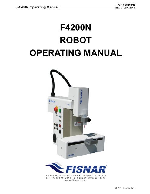
<strong>F4200N</strong> Operating <strong>Manual</strong><br />
Part # 562187N<br />
Rev. C Jun. 2011<br />
<strong>F4200N</strong><br />
ROBOT<br />
OPERATING MANUAL<br />
© 2011 <strong>Fisnar</strong> Inc.
<strong>F4200N</strong> Operating <strong>Manual</strong><br />
Part # 562187N<br />
Rev. C Jun. 2011<br />
THIS PAGE INTENTIONALLY LEFT BLANK<br />
© 2011 <strong>Fisnar</strong> Inc.
<strong>F4200N</strong> Operating <strong>Manual</strong><br />
Table of Contents<br />
Part # 562187N<br />
Rev. C Jun. 2011<br />
TABLE OF CONTENTS<br />
SECTION 1: INTRODUCTION .................................................................................... 4<br />
1. SAFETY PRECAUTIONS ........................................................................................................ 5<br />
2. PACKAGE CONTENTS .......................................................................................................... 6<br />
3. CONNECTOR AND SWITCH LOCATIONS ............................................................................... 7<br />
SECTION 2: SETUP .................................................................................................... 8<br />
1. UNPACKING THE ROBOT ..................................................................................................... 9<br />
2. SETUP ................................................................................................................................. 9<br />
SECTION 3: TEACHING OVERVIEW ......................................................................... 10<br />
1. TEACHING OVERVIEW ........................................................................................................ 11<br />
2. USING THE TEACH PENDANT .............................................................................................. 13<br />
2.1 Key Selection .......................................................................................................................................13<br />
2.2 Key Assignments ..................................................................................................................................14<br />
2.3 Data Entry ...........................................................................................................................................15<br />
2.4 Running a Program .............................................................................................................................15<br />
3. POINT TYPE & FUNCTION SUMMARY .................................................................................. 16<br />
3.1 Point Menu (F1) ..................................................................................................................................16<br />
3.2 Menu 1 (F2) .........................................................................................................................................18<br />
3.3 Utility Menu (Within Menu1) ...............................................................................................................19<br />
3.4 Menu 2 (F3) .........................................................................................................................................20<br />
3.5 Setup Menu (F4) ..................................................................................................................................21<br />
SECTION 4: PROGRAMMING EXAMPLE ................................................................. 23<br />
1. PROGRAMMING EXAMPLE ................................................................................................... 24<br />
2. GOOD PROGRAMMING PRACTICES ...................................................................................... 27<br />
3. EDITING A PROGRAM .......................................................................................................... 28<br />
3.1<br />
3.2<br />
Changing a Point’s XYZ location ........................................................................................................28<br />
Insert / Delete an Instruction ...............................................................................................................28<br />
4. CHANGING THE PROGRAM NUMBER ................................................................................... 29<br />
5. CHANGING FROM TEACH MODE TO RUN MODE .................................................................. 29<br />
SECTION 5: POINT TYPE & FUNCTION REFERENCE ............................................ 30<br />
1. F1 (POINT MENU) ............................................................................................................... 31<br />
1.1 Dispense Dot ........................................................................................................................................31<br />
1.2 Line Start .............................................................................................................................................31<br />
1.3 Line Passing.........................................................................................................................................32<br />
1.4 Circle ...................................................................................................................................................32<br />
1.5 Arc Point ..............................................................................................................................................33<br />
1.6 Line End ...............................................................................................................................................33<br />
1.7 End Program .......................................................................................................................................33<br />
1.8 Dispense ON / OFF .............................................................................................................................34<br />
1.9 GOTO Address .....................................................................................................................................35<br />
1.10 Step & Repeat X ...................................................................................................................................35<br />
1.11 Step & Repeat Y ...................................................................................................................................40<br />
1.12 Brush Area ...........................................................................................................................................41<br />
1.13 Call Subroutine ....................................................................................................................................48<br />
1.14 Call Program .......................................................................................................................................49<br />
1.15 Set I/O ..................................................................................................................................................49<br />
1.16 Wait Point ............................................................................................................................................50<br />
1.17 Stop Point ............................................................................................................................................50<br />
1.18 Home Point ..........................................................................................................................................50<br />
1.19 Loop Address .......................................................................................................................................50<br />
- Page 1 - © 2011 <strong>Fisnar</strong> Inc.
<strong>F4200N</strong> Operating <strong>Manual</strong><br />
Table of Contents<br />
Part # 562187N<br />
Rev. C Jun. 2011<br />
1.20 Dummy Point .......................................................................................................................................51<br />
1.21 Initialize ...............................................................................................................................................51<br />
1.22 Label ....................................................................................................................................................51<br />
1.23 Display Counter ...................................................................................................................................51<br />
1.24 Loop Counter .......................................................................................................................................51<br />
1.25 Dispense Output Setup .........................................................................................................................52<br />
2. F2 (MENU 1) ....................................................................................................................... 53<br />
2.1 Group Edit ...........................................................................................................................................53<br />
2.2 Expand Step & Repeat .........................................................................................................................60<br />
2.3 Program Name .....................................................................................................................................61<br />
2.4 Z-axis Limit (mm) ................................................................................................................................61<br />
2.5 Initial Output Port ...............................................................................................................................61<br />
2.6 Debug Speed (mm/s) ............................................................................................................................62<br />
2.7 Utility Menu .........................................................................................................................................62<br />
2.8 Jog Speed .............................................................................................................................................62<br />
2.9 Adjust Origin .......................................................................................................................................62<br />
2.10 Control by RS232 .................................................................................................................................62<br />
2.11 Resume .................................................................................................................................................63<br />
3. UTILITY MENU (WITHIN MENU 1) ....................................................................................... 64<br />
3.1 Program ...............................................................................................................................................64<br />
3.2 Memory ................................................................................................................................................64<br />
3.3 Teach Pendant .....................................................................................................................................65<br />
3.4 Relocate Data ......................................................................................................................................65<br />
3.5 Lock or Unlock Program .....................................................................................................................67<br />
3.6 Password Setup ....................................................................................................................................67<br />
3.7 Cycle Counter ......................................................................................................................................67<br />
3.8 Key Beep ..............................................................................................................................................68<br />
3.9 Test Function .......................................................................................................................................68<br />
4. F3 (MENU 2) ....................................................................................................................... 70<br />
4.1 Numerical Move ...................................................................................................................................70<br />
4.2 Save Temp Point ..................................................................................................................................70<br />
4.3 Move To Temp Point ............................................................................................................................70<br />
4.4 Undo Program .....................................................................................................................................70<br />
4.5 Redo Program ......................................................................................................................................70<br />
4.6 Debug Program ...................................................................................................................................70<br />
4.7 Move To Home Position ......................................................................................................................71<br />
4.8 System Information ..............................................................................................................................71<br />
4.9 Execute Point .......................................................................................................................................71<br />
4.10 Program List ........................................................................................................................................71<br />
5. F4 (SETUP MENU) ............................................................................................................... 72<br />
5.1 Line Speed ............................................................................................................................................72<br />
5.2 Line Dispense Setup .............................................................................................................................72<br />
5.3 Point Dispense Setup ...........................................................................................................................73<br />
5.4 Dispense End Setup .............................................................................................................................73<br />
5.5 Z Clearance .........................................................................................................................................75<br />
5.6 X/Y Move Speed ...................................................................................................................................76<br />
5.7 Z Move Speed .......................................................................................................................................76<br />
5.8 Home Position Setup ............................................................................................................................77<br />
5.9 Adjust Position Setup ...........................................................................................................................78<br />
5.10 Retract Setup ........................................................................................................................................80<br />
5.11 Quickstep .............................................................................................................................................82<br />
5.12 Auto Purge Setup .................................................................................................................................83<br />
5.13 ESTOP Output Status...........................................................................................................................83<br />
5.14 Acceleration .........................................................................................................................................84<br />
5.15 Pause Status .........................................................................................................................................84<br />
SECTION 6: SAMPLE PROGRAMS ........................................................................... 85<br />
1. DOTS, LINES AND ARCS – SAMPLE PROGRAM .................................................................... 86<br />
2. BRUSH AREA – SAMPLE PROGRAM ..................................................................................... 88<br />
3. STEP & REPEAT – SAMPLE PROGRAM ................................................................................ 89<br />
4. INPUT / OUTPUT SIGNAL PROCESSING – SAMPLE PROGRAM ............................................... 91<br />
SECTION 7: ERROR MESSAGES AND SPECIFICATIONS ...................................... 93<br />
- Page 2 - © 2011 <strong>Fisnar</strong> Inc.
<strong>F4200N</strong> Operating <strong>Manual</strong><br />
Table of Contents<br />
Part # 562187N<br />
Rev. C Jun. 2011<br />
1. ERROR MESSAGES .............................................................................................................. 94<br />
1.1 Point Closed Error ..............................................................................................................................94<br />
1.2 Need Line Start Point ...........................................................................................................................94<br />
1.3 Need Step & Repeat .............................................................................................................................94<br />
1.4 Unlock Program ..................................................................................................................................94<br />
1.5 Address Over Memory .........................................................................................................................95<br />
1.6 Move Over Memory .............................................................................................................................95<br />
1.7 System Error ........................................................................................................................................95<br />
2. I/O SPECIFICATIONS ............................................................................................................ 96<br />
2.1 Dispenser Connector: ..........................................................................................................................96<br />
2.2 Ext. Control Connector: ......................................................................................................................97<br />
2.3 Output Signals .....................................................................................................................................98<br />
2.4 Input Signals ........................................................................................................................................99<br />
2.5 Input / Output Schematic .....................................................................................................................100<br />
2.6 Input / Output Power Specifications ....................................................................................................100<br />
2.7 Robot External I/O Card ......................................................................................................................101<br />
3. SYSTEM SPECIFICATIONS .................................................................................................... 102<br />
4. MACHINE DIMENSIONS ....................................................................................................... 103<br />
4.1<br />
4.2<br />
<strong>F4200N</strong> Dimensions ............................................................................................................................103<br />
Work Table Dimensions .......................................................................................................................104<br />
SECTION 8:<br />
MAINTENANCE AND PERIODIC INSPECTION…………………………105<br />
1. CHECK CYCLES AND METHODS .......................................................................................... 106<br />
1.1 General Consideration ........................................................................................................................106<br />
1.2 Check Cycles and Points ......................................................................................................................106<br />
1.3 Check Methods .....................................................................................................................................107<br />
2. GREASING PROCEDURE ....................................................................................................... 108<br />
2.1 Grease Type and Greasing Interval .....................................................................................................108<br />
2.2 Accessing Parts to be Greased ............................................................................................................108<br />
- Page 3 - © 2011 <strong>Fisnar</strong> Inc.
<strong>F4200N</strong> Operating <strong>Manual</strong><br />
Section 1: Introduction<br />
Part # 562187N<br />
Rev. C Jun 2011<br />
SECTION 1: Introduction<br />
- Page 4 - © 2011 <strong>Fisnar</strong> Inc.
<strong>F4200N</strong> Operating <strong>Manual</strong><br />
Section 1: Introduction<br />
Part # 562187N<br />
Rev. C Jun 2011<br />
1. Safety Precautions<br />
1.1 Make sure the robot is connected to a properly grounded power source before<br />
operating.<br />
1.2 Keep away <strong>fr</strong>om any moving parts while the robot is running.<br />
1.3 Loading and unloading of parts and material must only be done when the robot is at<br />
a complete stop.<br />
1.4 Changing of fixtures or tooling must be done with the power source disconnected.<br />
1.5 The <strong>F4200N</strong> robot should only be operated in an environment between 0 and 40<br />
degrees Celsius with humidity of 20 to 95 percent and no visible condensation.<br />
1.6 Do not store or setup the robot in an area where it is directly exposed to sunlight.<br />
1.7 Do not operate the robot where electrical noise is present.<br />
1.8 Only use a neutral chemical for cleaning the robot. Do not use alcohol, benzene or<br />
thinner as it may damage the paint on the robot.<br />
1.9 Due to the electronic nature of this equipment and the potential for a spark or<br />
generation of heat, note that this equipment most NOT be used with any explosive<br />
material or in an explosive type environment.<br />
- Page 5 - © 2011 <strong>Fisnar</strong> Inc.
<strong>F4200N</strong> Operating <strong>Manual</strong><br />
Section 1: Introduction<br />
Part # 562187N<br />
Rev. C Jun 2011<br />
2. Package Contents<br />
In addition to this operating manual, the following items should be included with the robot:<br />
Main Unit<br />
(<strong>F4200N</strong>)<br />
Enclosure<br />
(CE Units Only – Not Included)<br />
Teach Pendant<br />
Barrel Holder<br />
Spare Screws and Hex Key<br />
Teach Pendant Cable<br />
Power Cord<br />
Dispenser Cable<br />
RS232 Cable and Null Modem Adapter<br />
(optional)<br />
Start / Stop Box<br />
(optional)<br />
- External Control Connector<br />
- Spare Control Connector<br />
- Barrel and Air Line<br />
- Page 6 - © 2011 <strong>Fisnar</strong> Inc.
<strong>F4200N</strong> Operating <strong>Manual</strong><br />
Section 1: Introduction<br />
Part # 562187N<br />
Rev. C Jun 2011<br />
3. Connector and Switch Locations<br />
Left side view<br />
Right side view<br />
- Page 7 - © 2011 <strong>Fisnar</strong> Inc.
<strong>F4200N</strong> Operating <strong>Manual</strong><br />
Section 2: Setup<br />
Part # 562187N<br />
Rev. C Jun 2011<br />
SECTION 2: Setup<br />
- Page 8 - © 2011 <strong>Fisnar</strong> Inc.
<strong>F4200N</strong> Operating <strong>Manual</strong><br />
Section 2: Setup<br />
Part # 562187N<br />
Rev. C Jun 2011<br />
1. Unpacking the Robot<br />
<br />
Always lift the robot <strong>fr</strong>om its base. Never lift the robot <strong>fr</strong>om the cross member.<br />
<br />
Remove all accessories <strong>fr</strong>om the shipping package before attempting to remove the<br />
robot.<br />
<br />
Place the robot on a stable workbench before operating.<br />
<br />
If possible, do not discard the packing material as these items may be needed if the<br />
robot is shipped or moved in the future.<br />
2. Setup<br />
F4200 robot is available with different configurations. The setup of each machine with its<br />
accessories will depend on the customer‟s application.<br />
If an enclosure is NOT being used, the enclosure door switch may be bypassed by<br />
connecting the plug labeled SHORTED (included in the robot accessories box) to<br />
the External Control Connector.<br />
2.1. When using an enclosure or light curtain connect the external start / stop box and<br />
enclosure door switch or light curtain to the External Control connector on the main<br />
unit. For further information, see SECTION 7.2.2: External Control Connector<br />
2.2. Connect one end of the Teach Pendant cable to the Teach Pendant and the other<br />
end to the Teach Pendant connection on the robot.<br />
2.3. Connect the power cord of the <strong>F4200N</strong> robot to the power socket on the robot. Be<br />
sure to use the correct power cord and power source for the robot model you are<br />
using (110 V or 220 V).<br />
2.4. Tie back all cables and air lines so that they will not interfere with the robot‟s motion<br />
when the robot is operating. Be sure that the cables and air lines do not restrict the<br />
motion of the robot‟s head and the robot‟s table and make sure that they cannot<br />
become jammed as the robot moves through the work area.<br />
- Page 9 - © 2011 <strong>Fisnar</strong> Inc.
<strong>F4200N</strong> Operating <strong>Manual</strong><br />
Section 3: Teaching Overview<br />
Part # 562187N<br />
Rev. C Jun 2011<br />
SECTION 3: Teaching Overview<br />
- Page 10 - © 2011 <strong>Fisnar</strong> Inc.
<strong>F4200N</strong> Operating <strong>Manual</strong><br />
Section 3: Teaching Overview<br />
Part # 562187N<br />
Rev. C Jun 2011<br />
1. Teaching Overview<br />
A program consists of a series of instructions stored in the main memory unit. Each<br />
instruction is stored in a numbered memory address. A memory address may record a<br />
point location with an X, Y, and Z-axis value and point type or it may store an instruction,<br />
which sets a parameter, such as a dispensing time or line speed.<br />
When the program is executed, the robot will go through each memory address in<br />
sequence and execute the instruction found there. If the memory address contains a point<br />
location, the robot will move the X, Y, and Z axes to that location. Depending on the type<br />
of point registered at that location, the robot may also perform other functions, such as<br />
turn the dispenser on or off.<br />
The most commonly used point types are Dispense Dot, Line Start, Line Passing, Arc<br />
Point, and Line End.<br />
To program the robot to dispense a „dot‟ of material, the dispensing tip must be jogged to<br />
the desired XYZ location, then that location is registered as a DISPENSE DOT point type<br />
by pressing the appropriate keys on the Teach Pendant.<br />
Dispense Dot<br />
To program the robot to dispense a bead of material along a linear path, the XYZ location<br />
of the start of the line is registered as a LINE START point type. The locations where the<br />
tip changes direction are registered as LINE PASSING points. The end of the line is<br />
registered as a LINE END point:<br />
- Page 11 - © 2011 <strong>Fisnar</strong> Inc.
<strong>F4200N</strong> Operating <strong>Manual</strong><br />
Section 3: Teaching Overview<br />
Part # 562187N<br />
Rev. C Jun 2011<br />
To dispense a bead of material in an arc, the XYZ location of the start of the line is<br />
registered as a LINE START point type. The high point of the arc is registered as an ARC<br />
POINT. The end of the arc is registered as a LINE END point:<br />
Lines and arcs can also be combined to dispense a bead of material along a complex<br />
path:<br />
Once the required point locations for your program have been taught, the teach pendant is<br />
no longer required. The unit can be switched to RUN mode and operated using the<br />
buttons and switches on the main unit control panel.<br />
- Page 12 - © 2011 <strong>Fisnar</strong> Inc.
<strong>F4200N</strong> Operating <strong>Manual</strong><br />
Section 3: Teaching Overview<br />
Part # 562187N<br />
Rev. C Jun 2011<br />
2. Using the Teach Pendant<br />
The teach pendant enables the user to jog the robot and input program data.<br />
If Shift is pressed,<br />
released, then the<br />
Speed key is<br />
pressed, Speed<br />
Setup is executed.<br />
If this key is<br />
pressed alone,<br />
Jump is executed.<br />
When entering<br />
numbers, this key is<br />
0.<br />
2.1 Key Selection<br />
There are several functions assigned to most keys on the Teach pendant. When a key is<br />
pressed alone, the function shown in the blue colored area on the key is executed. For<br />
example, Ins, Del, Jump, Clear and Esc are the default key functions, which are<br />
executed when that key is pressed alone.<br />
To access the function shown in the blue colored area at the top of a key, press and<br />
release the Shift key first (the LED on the Shift key will be flashing), then press the<br />
desired key. For example, to select the Speed function, press and release Shift, then<br />
press the Speed key.<br />
When a number is required, the teach pendant will automatically switch to numeric entry<br />
mode. The number represented by each key is shown in the lower right corner of the key.<br />
- Page 13 - © 2011 <strong>Fisnar</strong> Inc.
<strong>F4200N</strong> Operating <strong>Manual</strong><br />
Section 3: Teaching Overview<br />
Part # 562187N<br />
Rev. C Jun 2011<br />
2.2 Key Assignments<br />
Menu Keys<br />
Opens the<br />
Point Menu.<br />
Opens Menu<br />
1.<br />
Opens Menu 2.<br />
Opens the<br />
Setup Menu.<br />
Jog Keys<br />
Jogs the Y-axis in<br />
the forward<br />
direction.<br />
Jogs the Y-axis in<br />
the backward<br />
direction.<br />
Jogs the X-axis in<br />
the right direction.<br />
Jogs the X-axis in<br />
the left direction.<br />
Jogs the Z-axis DOWN.<br />
Jogs the Z-axis UP.<br />
Accelerates jog speed – used with X+, X-. Y+, Y-, Z Up, Z Down<br />
If the FAST button is pressed and held first, then one of the jog buttons is<br />
pressed, the axis will be jogged at the maximum jog speed.<br />
If one of the jog buttons is pressed first, then the FAST button is pressed, the jog<br />
motion will accelerate.<br />
If the FAST button is released, the jog motion will decelerate.<br />
Key Assignments<br />
Moves backward<br />
(1) memory<br />
address.<br />
Moves forward (1)<br />
memory address.<br />
Moves the tip to the<br />
point location<br />
currently in the<br />
display.<br />
Adjusts the tips<br />
position after a<br />
barrel change<br />
(Enter)–used to<br />
confirm data<br />
entries.<br />
Opens the Point<br />
registration menu.<br />
Changes the<br />
display to<br />
memory address<br />
number 1.<br />
Changes the<br />
display to the last<br />
memory address<br />
used in the<br />
program.<br />
Jumps to a<br />
specified memory<br />
address<br />
To run the<br />
program<br />
Inserts a memory address<br />
before the current address.<br />
Deletes the current memory<br />
address.<br />
Clears / erases the numeric<br />
value currently shown in the<br />
display.<br />
Homes the robot. Initializes<br />
all axes and moves the<br />
head to the position (0, 0,<br />
0).<br />
If pressed once, clears the current numeric value.<br />
If pressed twice, cancels the current function.<br />
If a program is running, cancels the running program.<br />
Changes <strong>fr</strong>om Point List display mode to Single Point<br />
display when teaching point data.<br />
- Page 14 - © 2011 <strong>Fisnar</strong> Inc.
<strong>F4200N</strong> Operating <strong>Manual</strong><br />
Section 3: Teaching Overview<br />
Part # 562187N<br />
Rev. C Jun 2011<br />
Key Functions<br />
→<br />
→<br />
→<br />
→<br />
→<br />
→<br />
Registers a DISPENSE<br />
DOT point. →<br />
Registers a LINE<br />
PASSING point. →<br />
Registers an ARC POINT.<br />
Registers a Point<br />
Dispense Setup<br />
→<br />
command.<br />
Registers the End<br />
Program command. →<br />
Undo<br />
→<br />
→<br />
Registers a LINE START<br />
point.<br />
Registers a LINE END<br />
point.<br />
Registers a Line Speed<br />
command.<br />
Registers a Line Dispense<br />
Setup command.<br />
Redo<br />
Registers a Z Clearance<br />
command.<br />
2.3 Data Entry<br />
When a number is required, the teach pendant will automatically switch to numeric entry<br />
mode. The number represented by each key is shown in the lower right corner of the key.<br />
2.4 Running a Program<br />
Press the<br />
key to run the program.<br />
- Page 15 - © 2011 <strong>Fisnar</strong> Inc.
<strong>F4200N</strong> Operating <strong>Manual</strong><br />
Section 3: Teaching Overview<br />
Part # 562187N<br />
Rev. C Jun 2011<br />
3. Point Type & Function Summary<br />
3.1 Point Menu (F1)<br />
Below is a list of Point Types, which are found under the F1 key (Point menu):<br />
Function<br />
Description<br />
Dispense Dot<br />
Line Start<br />
Line Passing<br />
Circle<br />
Arc Point<br />
Line End<br />
End Program<br />
Dispense On /<br />
Off<br />
GOTO<br />
Address<br />
Step & Repeat<br />
Brush Area<br />
Call<br />
Subroutine<br />
Registers the current XYZ location as a Dispense point for dot<br />
dispensing.<br />
Registers the current XYZ location as a Line Start point for line<br />
dispensing.<br />
Registers the current XYZ location as a Line Passing point. This is a<br />
location on the line where the tip changes direction, such as at the<br />
corner on a rectangle.<br />
Registers a circle with the circle center at the current XYZ location. The<br />
display will prompt the user for the circle diameter.<br />
Registers the current XYZ location as an Arc point. Arc points are used<br />
to dispense material in an arc or circle.<br />
Registers the current XYZ location as a Line End point.<br />
Registers the current memory address as the end of the program.<br />
Registers an instruction which turns the dispenser on or off at the<br />
current XYZ location.<br />
Causes the program to jump to the specified memory address.<br />
Registers an instruction that will re-run a selected group of memory<br />
addresses, stepping by a user-defined distance in the X or Y-axis after<br />
each copy. The matrix of parts is defined by specifying the number of<br />
rows, the number of columns, the X offset and the Y offset.<br />
Step & Repeat X indicates that the robot will give priority to the X-axis,<br />
running the parts along the X-axis first.<br />
Step & Repeat Y indicates that the robot will give priority to the Y-axis,<br />
running the parts along the Y-axis first.<br />
Causes the tip to „paint‟ the defined area. The painted area can be in<br />
the form of a rectangle or a circle / spiral.<br />
Causes the machine to jump to a specified memory address and<br />
execute the instructions found there. When the end program instruction<br />
is reached, program execution will continue at address just after the call<br />
Subroutine instruction.<br />
- Page 16 - © 2011 <strong>Fisnar</strong> Inc.
<strong>F4200N</strong> Operating <strong>Manual</strong><br />
Section 3: Teaching Overview<br />
Part # 562187N<br />
Rev. C Jun 2011<br />
Function<br />
Call Program<br />
Set I/O<br />
Wait Point<br />
Stop Point<br />
Home Point<br />
Loop Address<br />
Dummy Point<br />
Initialize<br />
Label<br />
Display<br />
Counter<br />
Loop Counter<br />
Line end 1<br />
Dispense<br />
Output Setup<br />
Description<br />
Jumps to the specified program number <strong>fr</strong>om within the current<br />
program.<br />
Registers an instruction, which either sets the value of an output signal<br />
or checks the status of an input signal.<br />
After executing the current point (Line start, passing, etc) the robot will<br />
wait a specified amount of time before moving to the next command.<br />
After executing the current point (Line start, passing, etc), the robot will<br />
wait until the start button is pressed before moving to the next<br />
command.<br />
Registers an instruction to „home‟ all axes, sending them to the home<br />
position. See the Setup Menu for instructions on changing the location<br />
of the home position.<br />
Causes the program to execute a group of memory addresses a userspecified<br />
number of times.<br />
Registers the current XYZ location as a Dummy point. The tip will<br />
simply pass through this point. Useful for avoiding obstacles on the<br />
work piece.<br />
Registers an Initialize point. Causes the robot to perform a mechanical<br />
initialization.<br />
Registers a label that can be used as a reference when used with the<br />
GOTO address, Loop address, Set I/O, Step & repeat X, Step & repeat<br />
Y and Call Subroutine commands.<br />
Shows a counter at the bottom of the teach pendant screen while a<br />
program is running.<br />
The Loop Counter either clears or keeps the current tally of the counter<br />
when an I/O signal is received. The tally is cumulatively added to the<br />
current count on the display counter.<br />
Registers the current memory address as the end of the “stadium” path<br />
setting.<br />
Defines the dispense output port number for line dispense setup.<br />
- Page 17 - © 2011 <strong>Fisnar</strong> Inc.
<strong>F4200N</strong> Operating <strong>Manual</strong><br />
Section 3: Teaching Overview<br />
Part # 562187N<br />
Rev. C Jun 2011<br />
3.2 Menu 1 (F2)<br />
Below is a list of functions, which are found under the Menu 1 key:<br />
Function<br />
Group Edit<br />
Expand Step & Repeat<br />
Program Name<br />
Z-axis Limit (mm)<br />
Initial Output Port<br />
Debug Speed<br />
Description<br />
Allows a function to be applied to a user-defined group<br />
of memory addresses. Functions include copy, delete,<br />
move, multiply line speed, multiply dispense times, apply<br />
X Offset, apply Y Offset, apply Z Offset<br />
Expands the memory address locations which would be<br />
performed at a Step & Repeat instruction so individual<br />
memory addresses of the repeated instructions can be<br />
edited<br />
Allows the user to register a name for the current<br />
program number<br />
Sets the MAXIMUM Z-axis value (the lowest tip<br />
position). Once the Z-axis limit is set, the robot will<br />
prevent the tip <strong>fr</strong>om jogging below the set location.<br />
Sets the status of the output signals when the machine<br />
is initialized<br />
Sets the speed used when running in Debug mode.<br />
Utility Menu Opens the Utility Menu. See Section 3 Chapter 3.3.<br />
Jog Speed<br />
Adjust Position<br />
Control by RS232<br />
Resume<br />
Allows the user to set the tip jog speed for teach mode:<br />
Low, Middle or High jog speed can be selected.<br />
See Section 3 Chapter 2.9 “Adjust Position Setup”<br />
Allows the robot to be controlled via the RS232 port<br />
Determines if a program will restart <strong>fr</strong>om point #1 or the<br />
point at which it was interrupted if a program is stopped<br />
by an emergency stop or the enclosure door switch<br />
open signal.<br />
- Page 18 - © 2011 <strong>Fisnar</strong> Inc.
<strong>F4200N</strong> Operating <strong>Manual</strong><br />
Section 3: Teaching Overview<br />
Part # 562187N<br />
Rev. C Jun 2011<br />
3.3 Utility Menu (Within Menu1)<br />
Below is a list of functions, which are found under Menu 1 (F2) -> Utility Menu:<br />
Function<br />
Program<br />
Memory<br />
Teach Pendant<br />
Relocate Data<br />
Lock Program<br />
Description<br />
Opens the Program utility menu. Allows programs to be<br />
copied, backed up, restored, or cleared.<br />
Opens the Memory utility menu. Allows the robot<br />
memory to be backed up, restored, or cleared.<br />
Opens the Teach Pendant utility menu. Allows the<br />
current program to be copied to the Teach Pendant for<br />
transferring to another robot.<br />
Allows the position of a program to be corrected using<br />
two reference points. Corrects for X offset, Y offset and<br />
angle of rotation.<br />
Locks or unlocks a program to enable or disable<br />
program editing<br />
Cycle Counter<br />
Password Setup<br />
Key Beep<br />
Test Function<br />
Allows the operator to set a number to the program<br />
cycle to run the program a number of times.<br />
Allows the password to be set or reset for the current<br />
program. Protects the program <strong>fr</strong>om unauthorized<br />
editing.<br />
Enabling Key Beep to produce a beep every time a key<br />
in the Teach Pendant is touched.<br />
Testing the Robot Sensor, Panel Connector, Input<br />
Output signal, Teach Pendant and Motor.<br />
- Page 19 - © 2011 <strong>Fisnar</strong> Inc.
<strong>F4200N</strong> Operating <strong>Manual</strong><br />
Section 3: Teaching Overview<br />
Part # 562187N<br />
Rev. C Jun 2011<br />
3.4 Menu 2 (F3)<br />
Below is a list of functions, which are found under the F3 key:<br />
Function<br />
Numerical Move<br />
Save Temp Point<br />
Move To Temp Point<br />
Undo Program<br />
Redo Program<br />
Debug Program<br />
Move To Home Position<br />
System Information<br />
Execute Point<br />
Program List<br />
Description<br />
Allows the tip to be positioned numerically by entering a<br />
number for the X, Y and Z values.<br />
Saves the current XYZ position in a temporary memory<br />
area numbered 1 – 9.<br />
Retrieves a XYZ position, which was stored with Save<br />
Temp Point.<br />
Cancels the last change to the program. Returns to the<br />
program state prior to the last change.<br />
Restores the last change to the program, which was<br />
canceled with Undo.<br />
Runs the program in Debug mode starting at the current<br />
point location.<br />
Causes the tip to move to the home position. The default<br />
home position is X=0, Y=0, Z=0<br />
Displays system information, including software version<br />
number, work area size and control board version<br />
Runs a selected command.<br />
Allows the operator to see all programs in the memory.<br />
- Page 20 - © 2011 <strong>Fisnar</strong> Inc.
<strong>F4200N</strong> Operating <strong>Manual</strong><br />
Section 3: Teaching Overview<br />
Part # 562187N<br />
Rev. C Jun 2011<br />
3.5 Setup Menu (F4)<br />
Below is a list of functions, which are found under the F4 key (Setup menu):<br />
Function<br />
Line Speed<br />
Line Dispense Setup<br />
Point Dispense Setup<br />
Dispense End Setup<br />
Z Clearance<br />
XY Move Speed<br />
Z Move Speed<br />
Home Position Setup<br />
Description<br />
Registers the LINE SPEED used for all lines <strong>fr</strong>om the<br />
current memory address forward until another Line<br />
Speed instruction is found.<br />
Registers the LINE DISPENSE SETUP values which<br />
sets dispensing wait time at the start of lines („head‟<br />
time), wait time at the passing points („Node‟ time) and<br />
waiting time at the end of lines („tail‟ time). The<br />
registered values will be used <strong>fr</strong>om the current memory<br />
address forward until another Line Dispense Setup<br />
instruction is found.<br />
Registers POINT DISPENSE SETUP values, which sets<br />
dispensing time and waiting time at the end of<br />
dispensing („tail‟ time) for dots. The registered values will<br />
be used <strong>fr</strong>om the current memory address forward until<br />
another POINT DISPENSE SETUP instruction is found.<br />
Registers the height and speed the tip should raise at<br />
the end of dispensing. The registered values will be<br />
used <strong>fr</strong>om the current memory address forward until<br />
another DISPENSE END SETUP instruction is found.<br />
Registers the addition distance the tip should rise,<br />
beyond the height set in Dispense End Setup, to allow<br />
obstacles to be cleared as the tip moves <strong>fr</strong>om one figure<br />
to another. Values will be used until another Z Clearance<br />
instruction is found.<br />
Sets the movement speed of the X and Y axes when<br />
moving <strong>fr</strong>om one figure to another in the program<br />
Sets the movement speed of the Z-axis when moving<br />
<strong>fr</strong>om one figure to another in the program<br />
Changes the position the robot moves to at the end of a<br />
program cycle.<br />
- Page 21 - © 2011 <strong>Fisnar</strong> Inc.
<strong>F4200N</strong> Operating <strong>Manual</strong><br />
Section 3: Teaching Overview<br />
Part # 562187N<br />
Rev. C Jun 2011<br />
Function<br />
Adjust Position Setup<br />
Retract Setup<br />
Quickstep<br />
Auto Purge Setup<br />
ESTOP Output Status<br />
Acceleration<br />
Pause Status<br />
Language<br />
Jog Speed<br />
Adjust Position<br />
Quick Step Path<br />
USB Up/Down Load<br />
Circle Delay Time<br />
Description<br />
Registers the current XYZ location as the Adjust<br />
Position. This reference point can later be used to<br />
correct the program location after the dispensing tip has<br />
been changed.<br />
Registers Retract values at the current XYZ location.<br />
Retract causes the tip to move up and back over the<br />
dispensed bead after line dispensing.<br />
Causes the robot to move very fast <strong>fr</strong>om one point to<br />
another reducing the time of the dispensing cycle.<br />
Automatically purges the system at the end of the<br />
program.<br />
After receiving the emergency stop signal, ESTOP<br />
Output Status can modify the status of all the outputs or<br />
leave them as before receiving the emergency signal.<br />
Parameter that controls the robot‟s acceleration<br />
Sets the position to which the tip moves after pressing<br />
the Start button. The tip can go to the Home position or<br />
will stay at the position where the Start button was<br />
pressed.<br />
Opens MENU for selecting the Language<br />
Allows the user to set the tip jog speed for teach mode:<br />
Low, Middle or High jog speed can be selected.<br />
See Section 3 Chapter 2.9 “Adjust Position Setup”<br />
Allows the tip to move faster when dispensing.<br />
Allows the operator to upload or download<br />
program/programs and software updates.<br />
Circle Delay Time allows the robot to stop at the end of<br />
a circle and allow excess material to be removed before<br />
the robot carries to the next point.<br />
- Page 22 - © 2011 <strong>Fisnar</strong> Inc.
<strong>F4200N</strong> Operating <strong>Manual</strong><br />
Section 4: Programming Example<br />
Part # 562187N<br />
Rev. C Jun 2011<br />
SECTION 4: Programming<br />
Example<br />
- Page 23 - © 2011 <strong>Fisnar</strong> Inc.
<strong>F4200N</strong> Operating <strong>Manual</strong><br />
Section 4: Programming Example<br />
Part # 562187N<br />
Rev. C Jun 2011<br />
1. Programming Example<br />
To help you become familiar with programming the robot, please follow the instructions<br />
below to create a program, which dispenses in the following pattern:<br />
8: Dispense Dot 9: Dispense Dot<br />
10: Dispense Dot<br />
Notes:<br />
We will create the above program in program # 10.<br />
<br />
We will use a line speed of 40 mm / second for the lines and arcs in the program<br />
For dots, we will use a dispensing time of 0.50 seconds and a waiting time of 0.1<br />
seconds after dispensing<br />
- Page 24 - © 2011 <strong>Fisnar</strong> Inc.
<strong>F4200N</strong> Operating <strong>Manual</strong><br />
Section 4: Programming Example<br />
Part # 562187N<br />
Rev. C Jun 2011<br />
Instruction<br />
Display Shows<br />
1<br />
Follow the instructions found in SECTION 2:2.<br />
Setup to setup the robot.<br />
2<br />
3<br />
4<br />
5<br />
6<br />
Select program 10 using the program number<br />
selection switches on the main unit control panel.<br />
Turn the power on.<br />
Press the START button. The robot will move to<br />
the home position.<br />
Press the Setup key, then 1 to select Line Speed<br />
to register a line speed of 40 mm/second at<br />
memory address number 1.<br />
The robot is now waiting for the speed to be<br />
registered. Press 40 then ENTER to register a<br />
speed of 40 mm / second.<br />
The display shows we are at memory address 2<br />
and that it is empty.<br />
Jog the dispensing tip to the first location in the<br />
diagram above (1: Line Start).<br />
To jog the X and Y-axes, press the arrow keys<br />
X, X, Y and Y.<br />
To jog the Z-axis, press the Z and Z keys.<br />
[MACHINE HOME]<br />
+------------+<br />
| START/HOME |<br />
+------------+<br />
ADDR:1<br />
EMPTY<br />
PROG:10<br />
X:0.00 Y:0.00 Z:0.00<br />
Line Speed Setup<br />
----------------<br />
Speed:<br />
unit: mm/sec<br />
ADDR:2 PROG:10<br />
EMPTY<br />
7<br />
8<br />
Press and hold the FAST key to jog fast. See<br />
Error! Reference source not found. Jogging for<br />
more information.<br />
Once the tip is at the correct X, Y, Z location for<br />
the first point (1: Line Start), press the ENTER<br />
key, then 2 to register the location as a Line Start<br />
point.<br />
The display will show we are at memory address<br />
3 and it is empty. Jog the tip to the X, Y, Z<br />
location of the second point (2: Line Passing).<br />
When the location is correct, press the ENTER<br />
key, then 3 to register the location as a Line<br />
Passing point.<br />
ADDR:3<br />
EMPTY<br />
ADDR:4<br />
EMPTY<br />
PROG:10<br />
PROG:10<br />
- Page 25 - © 2011 <strong>Fisnar</strong> Inc.
<strong>F4200N</strong> Operating <strong>Manual</strong><br />
Section 4: Programming Example<br />
9<br />
10<br />
11<br />
12<br />
13<br />
14<br />
15<br />
16<br />
17<br />
18<br />
19<br />
Instruction<br />
Now jog the tip to the location of the third point<br />
(3: Arc Point). When the location is correct,<br />
press the ENTER key, then 5 to register the<br />
location as an Arc point.<br />
Jog the tip to the location of the fourth point<br />
(4: Line Passing). When the location is correct,<br />
press the ENTER key, then 3 key to register the<br />
location as a Line Passing point.<br />
Jog the tip to the location of the fifth point<br />
(5: Line Passing). When the location is correct,<br />
press the ENTER key, then 3 to register the<br />
location as a Line Passing point.<br />
Jog the tip to the location of the sixth point<br />
(6: Line Passing). When the location is correct,<br />
press the ENTER key, then 3 to register the<br />
location as a Line Passing point.<br />
Jog the tip to the location of the seventh point<br />
(7: Line End). When the location is correct, press<br />
the ENTER key, then 6 to register the location as<br />
a Line End point.<br />
The line is now complete. The next step is to<br />
register the dispense settings for the dots.<br />
Press the SETUP key, then 3 to register the dot<br />
dispensing time.<br />
Type 0.5 to register a dispensing time of 0.5<br />
seconds, and then press ENTER.<br />
Type 0.1 to register a waiting time after<br />
dispensing of 0.1 seconds, and then press<br />
ENTER.<br />
Jog the tip to the location of first dispense dot<br />
(8: Dispense Dot). When the location is correct,<br />
press the ENTER key, then 1 to register the<br />
location as a Dispense Dot.<br />
Jog the tip to the location of second dispense dot<br />
(9: Dispense Dot). When the location is correct,<br />
press the ENTER key, then 1 to register the<br />
location as a Dispense Dot.<br />
Jog the tip to the location of third dispense dot<br />
(10: Dispense Dot). When the location is correct,<br />
press the ENTER key, then 1 to register the<br />
location as a Dispense Dot.<br />
The program is now complete.<br />
Press ENTER, then 7 to register address 13 as<br />
the END of the program.<br />
20 To run the program, press the RUN key.<br />
ADDR:5<br />
EMPTY<br />
ADDR:6<br />
EMPTY<br />
ADDR:7<br />
EMPTY<br />
ADDR:8<br />
EMPTY<br />
ADDR:9<br />
EMPTY<br />
Display Shows<br />
Part # 562187N<br />
Rev. C Jun 2011<br />
PROG:10<br />
PROG:10<br />
PROG:10<br />
PROG:10<br />
PROG:10<br />
Point Dispense Setup<br />
--------------------<br />
Dis. Time:<br />
Tail Time:<br />
unit: sec<br />
ADDR:10<br />
EMPTY<br />
ADDR:11<br />
EMPTY<br />
ADDR:12<br />
EMPTY<br />
ADDR:13<br />
EMPTY<br />
ADDR:14<br />
EMPTY<br />
PROG:10<br />
PROG:10<br />
PROG:10<br />
PROG:10<br />
PROG:10<br />
- Page 26 - © 2011 <strong>Fisnar</strong> Inc.
<strong>F4200N</strong> Operating <strong>Manual</strong><br />
Section 4: Programming Example<br />
Part # 562187N<br />
Rev. C Jun 2011<br />
2. Good Programming Practices<br />
It is recommended to register the setup commands at the beginning of every program.<br />
The following setup commands are the most commonly used:<br />
<br />
<br />
<br />
<br />
<br />
<br />
<br />
Dispense End Setup<br />
Point Dispense Setup<br />
Line Dispense Setup<br />
Line Speed<br />
Z Clearance<br />
Retract Setup<br />
Adjust Position Setup<br />
For a complete list and description of all the different setup commands, refer to SECTION<br />
3:4.2 F4 (Setup Menu) and SECTION 5:2 Setup Menu.<br />
- Page 27 - © 2011 <strong>Fisnar</strong> Inc.
<strong>F4200N</strong> Operating <strong>Manual</strong><br />
Section 4: Programming Example<br />
Part # 562187N<br />
Rev. C Jun 2011<br />
3. Editing a Program<br />
You can move through the instructions in an existing program by using the following keys:<br />
Key Function<br />
+1 Moves forward (1) memory address<br />
-1 Moves backward (1) memory address<br />
FIRST Moves to the first memory address in the program<br />
END Moves to the last programmed memory address in the program<br />
+10 Jumps forward (10) memory addresses<br />
-10 Jumps backward (10) memory addresses<br />
MOVE Moves the tip to the XYZ point location of the selected point<br />
JUMP Jumps to display the specified memory address<br />
3.1 Changing a Point’s XYZ location<br />
To change the XYZ location of a point, press the +1 or –1 key until the point you want to<br />
change is shown in the display.<br />
You can confirm that the correct point is in the display by pressing the MOVE key. This will<br />
cause the tip to move to the XYZ position shown in the display.<br />
Now use the jog keys (X, X, Y and Y) and the Z / Z keys to jog the tip to the<br />
new location.<br />
Once the location is correct, simply re-register the point as you did when it was first taught,<br />
by pressing the ENTER key and selecting the point type. The point will be re-registered at<br />
the new location.<br />
3.2 Insert / Delete an Instruction<br />
<br />
To insert an instruction, press the INS key. The point currently shown in the display<br />
will be moved forward one memory address. A new, empty memory address will be<br />
inserted at the current memory address.<br />
<br />
To delete the instruction currently shown in the display, press the DEL key, and<br />
then press the F1 (Yes) key.<br />
- Page 28 - © 2011 <strong>Fisnar</strong> Inc.
<strong>F4200N</strong> Operating <strong>Manual</strong><br />
Section 4: Programming Example<br />
Part # 562187N<br />
Rev. C Jun 2011<br />
4. Changing the Program Number<br />
The program number is selected by the program number selection switches on the main<br />
unit‟s control panel.<br />
Press the + and – buttons to select the program number.<br />
Note: Program 99 is designed for “autorun” on Run mode. When starting the robot with<br />
this program, the robot starts automatically without pressing the Start/Home key for<br />
initialization.<br />
5. Changing <strong>fr</strong>om Teach Mode to Run Mode<br />
To change <strong>fr</strong>om Teach mode to Run mode, change the position of the mode switch on the<br />
main unit‟s control panel.<br />
When the machine is in Run mode, the teaching box (teach pendant) is not required.<br />
Programs can be selected and run using the switches on the <strong>fr</strong>ont control panel of the<br />
main unit.<br />
- Page 29 - © 2011 <strong>Fisnar</strong> Inc.
<strong>F4200N</strong> Operating <strong>Manual</strong><br />
Section 5: Point Type & Function Reference<br />
Part # 562187N<br />
Rev. C Jun 2011<br />
SECTION 5: Point Type & Function<br />
Reference<br />
- Page 30 - © 2011 <strong>Fisnar</strong> Inc.
<strong>F4200N</strong> Operating <strong>Manual</strong><br />
Section 5: Point Type & Function Reference<br />
Part # 562187N<br />
Rev. C Jun 2011<br />
1. F1 (Point Menu)<br />
Below is a list of functions which are found under the ENTER key. These functions are<br />
„point-type‟ functions, meaning that the values applied will occupy one memory address.<br />
Please see SECTION 6:Sample Programs for additional programming examples.<br />
1.1 Dispense Dot<br />
Registers the current XYZ location as a dispense point for dot dispensing.<br />
The dispense time and wait time must be set in a previous memory address by registering<br />
a Point Dispense Setup instruction.<br />
The upward motion of the tip after dispensing can be controlled by registering a Dispense<br />
End Setup instruction and / or a Z Clearance instruction in a previous memory address.<br />
Dispense End Setup and Z Clearance instructions are registered using the SETUP key.<br />
See also SECTION 5:5.3 Point Dispense Setup, SECTION 5:5.4 Dispense End Setup<br />
and SECTION 5:5.5 Z Clearance.<br />
1.2 Line Start<br />
Registers the current XYZ location as a Line Start point for line dispensing.<br />
The line speed must be set in a previous memory address by registering a Line Speed<br />
instruction using the SETUP key.<br />
Dispense delay times used at Line Start and Line End points can be controlled by<br />
registering a Line Dispense Setup instruction in a previous memory address. The Line<br />
Dispense Setup instruction is registered by pressing the SETUP key.<br />
See also SECTION 5:5.1 Line Speed and SECTION 5:5.2 Line Dispense Setup.<br />
- Page 31 - © 2011 <strong>Fisnar</strong> Inc.
<strong>F4200N</strong> Operating <strong>Manual</strong><br />
Section 5: Point Type & Function Reference<br />
Part # 562187N<br />
Rev. C Jun 2011<br />
1.3 Line Passing<br />
Registers the current XYZ location as a Line Passing point. This is a location on the line<br />
where the tip changes direction, such as at the corner on a rectangle.<br />
Also use a Line passing point before and after an Arc Point instruction.<br />
1.4 Circle<br />
Registers a circle, where the circle‟s center is at the current XYZ location. To register a<br />
circle, jog the tip to the circle‟s center and press ENTER, and then press the key 4 (for<br />
circle). The display will prompt you to type the following data:<br />
Diameter: Type the diameter of the circle and press ENTER.<br />
Over Angle: (The value is <strong>fr</strong>om 1~360). After dispensing the circle, while going through an<br />
extra part of the circle defined by the Over Angle, the dispenser will be<br />
turned OFF.<br />
Z Lift: 1. Yes 2. No<br />
Selection:<br />
If you want the Z-axis (tip) to lift while going through the Over Angle, you<br />
must select 1. Otherwise: select 2.<br />
The speed must be set in a previous memory address by registering a Line Speed<br />
instruction using the SETUP key.<br />
Dispense delay times used at the start of the circle and at the end of the circle can be<br />
controlled by registering a Line Dispense Setup instruction in a previous memory<br />
address. The Line Dispense Setup instruction is registered by pressing the SETUP key.<br />
See also SECTION 5:5.1 Line Speed and SECTION 5:5.2 Line Dispense Setup.<br />
The upward motion of the tip after dispensing can be controlled by registering a Dispense<br />
End Setup instruction and / or a Z Clearance instruction in a previous memory address.<br />
Dispense End Setup and Z Clearance instructions are registered using the SETUP key.<br />
See also SECTION 5:5.4 Dispense End Setup and SECTION 5:5.5 Z Clearance.<br />
- Page 32 - © 2011 <strong>Fisnar</strong> Inc.
<strong>F4200N</strong> Operating <strong>Manual</strong><br />
Section 5: Point Type & Function Reference<br />
Part # 562187N<br />
Rev. C Jun 2011<br />
1.5 Arc Point<br />
Registers the current XYZ location as an Arc Point. Arc points are used to dispense<br />
material along an arc or circular path.<br />
See SECTION 4: Programming Example, for an example of the use of an Arc point.<br />
1.6 Line End<br />
Registers the current XYZ location as a Line End point.<br />
The dispense delay time used at the end of the line can be controlled by registering a Line<br />
Dispense Setup instruction in a previous memory address. The Line Dispense Setup<br />
instruction is registered by pressing the SETUP key.<br />
See also SECTION 5:5.2 Line Dispense Setup.<br />
The upward motion of the tip after dispensing can be controlled by registering a Dispense<br />
End Setup instruction and / or a Z Clearance instruction in a previous memory address.<br />
Dispense End Setup and Z Clearance instructions are registered using the SETUP key.<br />
1.7 End Program<br />
Registers the current memory address as the end of the program. The end program<br />
instruction will cause the tip to return to the home position at the end of the program cycle.<br />
- Page 33 - © 2011 <strong>Fisnar</strong> Inc.
<strong>F4200N</strong> Operating <strong>Manual</strong><br />
Section 5: Point Type & Function Reference<br />
Part # 562187N<br />
Rev. C Jun 2011<br />
1.8 Dispense ON / OFF<br />
The Dispense ON / OFF instruction will allow the user to program an instruction which will<br />
turn the dispenser ON or OFF.<br />
This is useful for turning the dispenser OFF before the end of a line to prevent excess<br />
material at the line end.<br />
Problem: Too much material at the end of the line<br />
Solution: Turn the dispenser OFF before the end of the line<br />
Turn Dispenser Off here<br />
Continue moving to end of line<br />
To register a DISPENSE OFF instruction, jog the tip to the XYZ location where you want<br />
the dispenser OFF, enter that location as a Line Passing point, then press the ENTER key<br />
and select Dispense ON / OFF.<br />
Press 1 to select Dispenser ON, or press 2 to select Dispenser OFF.<br />
- Page 34 - © 2011 <strong>Fisnar</strong> Inc.
<strong>F4200N</strong> Operating <strong>Manual</strong><br />
Section 5: Point Type & Function Reference<br />
Part # 562187N<br />
Rev. C Jun 2011<br />
1.9 GOTO Address<br />
The GOTO Address function causes the program to jump to a specified memory address.<br />
1.10 Step & Repeat X<br />
Step & Repeat X allows a group of instructions to be run repeatedly, stepping a given<br />
distance in the X-axis or Y-axis between each cycle.<br />
Step & Repeat X is useful when a fixture is mounted on the robot, which holds many<br />
identical work pieces aligned in rows and columns. The user needs only to create a<br />
program for the first work piece in the fixture, and then use the Step & Repeat function to<br />
dispense to the other work pieces.<br />
The Step & Repeat function will allow the user to define the number of rows, the number<br />
of columns, the X Offset between each part, and the Y Offset between each part.<br />
If, for example, we have a program (number 20) which dispenses four dots of material on<br />
a work piece:<br />
- Page 35 - © 2011 <strong>Fisnar</strong> Inc.
<strong>F4200N</strong> Operating <strong>Manual</strong><br />
Section 5: Point Type & Function Reference<br />
Part # 562187N<br />
Rev. C Jun 2011<br />
The program would consist of the following eight instructions:<br />
Address<br />
Instruction<br />
1<br />
2<br />
3<br />
Dispense End Setup:<br />
H.Speed = 100 mm/s, L.Speed = 15 mm/s, L.Length = 5mm<br />
Z Clearance:<br />
Relative 10 mm<br />
Point Dispense Setup:<br />
Disp.Time = 0.25 s Tail Time = 0.10 s<br />
4 Dispense Point<br />
5 Dispense Point<br />
6 Dispense Point<br />
7 Dispense Point<br />
8 End Program<br />
If a fixture is made which holds (12) work pieces, in four columns by three rows:<br />
Y Offset<br />
25 mm<br />
X Offset<br />
30 mm<br />
A Step & Repeat X instruction can be used to repeat the program at the additional (11)<br />
locations.<br />
- Page 36 - © 2011 <strong>Fisnar</strong> Inc.
<strong>F4200N</strong> Operating <strong>Manual</strong><br />
Section 5: Point Type & Function Reference<br />
Part # 562187N<br />
Rev. C Jun 2011<br />
The instruction at memory address 8 should be changed <strong>fr</strong>om End Program to Step &<br />
Repeat X. To register a Step & Repeat X instruction at memory address 8, do the<br />
following:<br />
1<br />
2<br />
3<br />
Instruction<br />
Press the +1 or –1 keys until memory address 8<br />
is shown in the display<br />
Press the Enter key, and then press the X key<br />
to change to page 2. Select Step & Repeat by<br />
pressing the key 3.<br />
Type 1 to select X direction, and then press<br />
ENTER.<br />
The display will prompt you for the Start Addr:<br />
Display Shows<br />
ADDR: 8 PROG: 20<br />
End Program<br />
Step & Repeat<br />
Address, 8<br />
---------------------<br />
1.X 2.Y,<br />
Start Address,<br />
Columns (X):<br />
Rows (Y):<br />
Step & Repeat<br />
Address, 8<br />
---------------------<br />
1.X 2.Y, 1<br />
Start Address,<br />
Columns (X):<br />
Rows (Y):<br />
[F1] Address [F2]Label<br />
4<br />
5<br />
The start address is the memory address of the<br />
first instruction, which is part of this Step &<br />
Repeat group.<br />
In our example, we want to repeat all instructions<br />
starting with memory address number 4.<br />
Type 4 to specify memory address 4, and then<br />
press ENTER.<br />
Type 4 to specify four columns, and then press<br />
ENTER.<br />
Step & Repeat<br />
Address, 8<br />
---------------------<br />
1.X 2.Y, 1<br />
Start Address, 4<br />
Columns (X):<br />
Rows (Y):<br />
Step & Repeat<br />
Address, 8<br />
---------------------<br />
1.X 2.Y, 1<br />
Start Address, 4<br />
Columns (X): 4<br />
Rows (Y):<br />
- Page 37 - © 2011 <strong>Fisnar</strong> Inc.
<strong>F4200N</strong> Operating <strong>Manual</strong><br />
Section 5: Point Type & Function Reference<br />
Part # 562187N<br />
Rev. C Jun 2011<br />
6<br />
7<br />
8<br />
Instruction<br />
Type 3 to specify three rows, and then press<br />
ENTER.<br />
In the above example, the X Offset between<br />
parts is 30 mm.<br />
Type 30 to specify an X Offset of 30 mm, and<br />
then press ENTER.<br />
In the above example, the Y Offset between<br />
parts is 25 mm.<br />
Type 25 to specify 25 mm, and then press<br />
ENTER.<br />
The display will prompt you to select 1. S Path or<br />
2. N. Path.<br />
Display Shows<br />
Step & Repeat<br />
Address, 8<br />
---------------------<br />
X Offset:<br />
Y Offset:<br />
Unit: mm<br />
Step & Repeat<br />
Address, 8<br />
---------------------<br />
X Offset: 30<br />
Y Offset:<br />
Unit: mm<br />
Step & Repeat<br />
Address, 8<br />
---------------------<br />
1. S Path<br />
2. N Path<br />
Select:<br />
9<br />
Selecting S Path will cause the first row 1 to 4 to<br />
be dispensed, then the second row 4 to 1, and<br />
then the third row 1 to 4.<br />
Selecting N PATH will cause the first row 1 to 4<br />
to be dispensed, then the second row 1 to 4, and<br />
then the third row 1 to 4.<br />
Addr: 9<br />
Empty<br />
Prog:20<br />
Press 1 to select S PATH, and then press<br />
ENTER.<br />
The program is now complete.<br />
10<br />
Press ENTER, and then select End Program to<br />
mark address 9 as the new End Program<br />
instruction.<br />
Addr: 10<br />
Empty<br />
Prog:20<br />
Press the 7 key then press ENTER.<br />
Press RUN to run the program.<br />
- Page 38 - © 2011 <strong>Fisnar</strong> Inc.
<strong>F4200N</strong> Operating <strong>Manual</strong><br />
Section 5: Point Type & Function Reference<br />
Part # 562187N<br />
Rev. C Jun 2011<br />
The program will run in the following pattern and consists of the following instructions:<br />
1 2 3 4<br />
8 7 6 5<br />
9 10 11 12<br />
Address<br />
Instruction<br />
1<br />
2<br />
3<br />
Dispense End Setup:<br />
H.Speed = 100 mm/s, L.Speed = 15 mm/s, L.Length = 5mm<br />
Z Clearance:<br />
Relative 10 mm<br />
Point Dispense Setup:<br />
Disp.Time = 0.25 s Tail Time = 0.10 s<br />
4 Dispense Point<br />
5 Dispense Point<br />
6 Dispense Point<br />
7 Dispense Point<br />
8<br />
Step & Repeat X:<br />
Cols: 4, Rows: 3, X Off: 30mm, Y Off: 25mm, Addr. 4, S Path<br />
9 End Program<br />
- Page 39 - © 2011 <strong>Fisnar</strong> Inc.
<strong>F4200N</strong> Operating <strong>Manual</strong><br />
Section 5: Point Type & Function Reference<br />
Part # 562187N<br />
Rev. C Jun 2011<br />
The previous example was done using S Path. The difference between S Path and N Path<br />
is the order in which the pieces are run:<br />
Step & Repeat X:<br />
S PATH<br />
1 2 3 4<br />
N PATH<br />
1 2 3 4<br />
8 7 6 5<br />
5 6 7 8<br />
9 10 11 12<br />
9 10 11 12<br />
1.11 Step & Repeat Y<br />
Step & Repeat Y works just as Step & Repeat X does, with one difference: priority is given<br />
to the Y-axis instead of the X-axis.<br />
Step & Repeat Y - S PATH<br />
1 6 7 12<br />
Step & Repeat Y - N PATH<br />
1 4 7 10<br />
2 5 8 11<br />
2 5 8 11<br />
3 4 9 10<br />
3 6 9 12<br />
- Page 40 - © 2011 <strong>Fisnar</strong> Inc.
<strong>F4200N</strong> Operating <strong>Manual</strong><br />
Section 5: Point Type & Function Reference<br />
Part # 562187N<br />
Rev. C Jun 2011<br />
1.12 Brush Area<br />
The Brush Area command causes the tip to „paint‟ a defined area.<br />
There are six Brush Area types: Rectangle, Circle, Rectangle 1, Rectangle Band, Circle<br />
Band and Circle1. The next pages provide a detailed description of all the Brush area<br />
types.<br />
To register a Brush Area command, follow the instructions below.<br />
Instruction<br />
1 Press ENTER to open the Point Menu<br />
2 Press X, to go to page 2<br />
3 Press 4 to select Brush Area.<br />
4<br />
Press the numeric key corresponding to<br />
the brush area type then press ENTER<br />
Type the width value and press ENTER.<br />
Display Shows<br />
[POINT] 1/3<br />
1 Dispense Dot<br />
2 Line Start<br />
.<br />
.<br />
7 End Program<br />
[POINT] 2/3<br />
.<br />
.<br />
4 Brush Area<br />
.<br />
Brush Area Setup<br />
------------------<br />
1.Rectangle 4.Rect Band<br />
2.Circle 5.Circle Band<br />
3.Rectangle 1 6. Circle 1<br />
Select:<br />
Brush Area Setup<br />
------------------<br />
1.Rectangle 4.Rect Band<br />
2.Circle 5.Circle Band<br />
3.Rectangle 1 6.Circle 1<br />
Width(mm):<br />
Band(mm):<br />
5<br />
Type the band value and press ENTER.<br />
Width and band values will be explained<br />
further in this section.<br />
- Page 41 - © 2011 <strong>Fisnar</strong> Inc.
<strong>F4200N</strong> Operating <strong>Manual</strong><br />
Section 5: Point Type & Function Reference<br />
Part # 562187N<br />
Rev. C Jun 2011<br />
1.12.1 Brush Area: Rectangle<br />
Brush Area Rectangle causes the tip to „paint‟ the defined area by passing back and forth<br />
along the X-axis, while moving the Y-axis a determined Brush Width distance after each<br />
pass along the X-axis.<br />
After registering the Brush Area Rectangle command, teach a Line Start point at the top<br />
left corner of the area to be brushed and a Line End point at the bottom right corner of that<br />
area (the tip will not dispense a straight line between these two points):<br />
Line Start<br />
Paint<br />
Area<br />
Line End<br />
If, for example, a brush width of 5 mm was used, the tip will take the following path when<br />
the program is run:<br />
5 mm<br />
5 mm<br />
5 mm<br />
5 mm<br />
- Page 42 - © 2011 <strong>Fisnar</strong> Inc.
<strong>F4200N</strong> Operating <strong>Manual</strong><br />
Section 5: Point Type & Function Reference<br />
Part # 562187N<br />
Rev. C Jun 2011<br />
1.12.2 Brush Area: Circle<br />
Brush Area Circle causes the tip to „paint‟ the defined area by following a spiral path <strong>fr</strong>om<br />
the outside limit of the circle to the center of the circle. It works in reverse of the Circle 1<br />
function.<br />
After registering the Brush Area Circle command, jog the tip to a point on the outside limit<br />
of the circle to be brushed and register that location as a Line Start point. Then jog the tip<br />
directly across to the center of the circle and register that location as a Line End point (the<br />
tip will not dispense a straight line between these two points):<br />
Paint<br />
Line Start<br />
Line End<br />
Area<br />
If, for example, a brush width of 5 mm was used, the tip will take the following path when<br />
the program is run:<br />
Closed Circle: <strong>fr</strong>om Outside of the Circle to the Center Open Circle: <strong>fr</strong>om Center of the Circle to out<br />
An open or closed option is also available for this function. Selecting the Closed option will<br />
make a whole circle first before making the spiral. Selecting the Open option will make the<br />
spiral without closing the outer circle.<br />
- Page 43 - © 2011 <strong>Fisnar</strong> Inc.
5mm<br />
<strong>F4200N</strong> Operating <strong>Manual</strong><br />
Section 5: Point Type & Function Reference<br />
Part # 562187N<br />
Rev. C Jun 2011<br />
1.12.3 Brush Area: Rectangle 1<br />
Brush Area Rectangle 1 causes the tip to „paint‟ the defined area by following a square<br />
spiral path <strong>fr</strong>om the outside of the rectangle to the center.<br />
After registering the Brush Area Rectangle 1 command, teach a Line Starting point at the<br />
top left corner of the area to be brushed and a Line End point at the bottom right corner of<br />
that area (the tip will not dispense a straight line between these two points):<br />
Line Start<br />
Paint<br />
Area<br />
Line End<br />
If, for example, a brush width of 5 mm was used, the tip will take the following path when<br />
the program is run:<br />
5 mm<br />
- Page 44 - © 2011 <strong>Fisnar</strong> Inc.
<strong>F4200N</strong> Operating <strong>Manual</strong><br />
Section 5: Point Type & Function Reference<br />
Part # 562187N<br />
Rev. C Jun 2011<br />
1.12.4 Brush Area: Rect. Band<br />
Brush Area Rect. Band causes the tip to „paint‟ a defined rectangular band area by<br />
following a square spiral path <strong>fr</strong>om the outside of the rectangle to the center.<br />
After registering the Brush Area Rect. Band command, teach a Line Start point at the top<br />
left corner of the area to be brushed and a Line End point at the bottom right corner of that<br />
area (the tip will not dispense a straight line between these two points):<br />
Line Start<br />
Line End<br />
If, for example, a brush width of 5 mm and band of 10mm was used, the tip will take the<br />
following path when the program is run:<br />
Width 5mm<br />
Band 10mm<br />
- Page 45 - © 2011 <strong>Fisnar</strong> Inc.
<strong>F4200N</strong> Operating <strong>Manual</strong><br />
Section 5: Point Type & Function Reference<br />
Part # 562187N<br />
Rev. C Jun 2011<br />
1.12.5 Brush Area: Circle Band<br />
Brush Area Circle Band causes the tip to „paint‟ a defined circular band area by following a<br />
spiral path <strong>fr</strong>om the outside limit of the circle to the center of the circle.<br />
After registering the Brush Area Circle Band command, jog the tip to a point on the outside<br />
limit of the circle to be brushed and register that location as a Line Start point. Then jog the<br />
tip directly across to the center of the circle and register that location as a Line End point<br />
(the tip will not dispense a straight line between these two points):<br />
Paint Area<br />
Line Start<br />
Line End<br />
If, for example, a brush width of 5 mm and Band of 15mm was used, the tip will take the<br />
following path when the program is run:<br />
Width = 5mm<br />
Band=15mm<br />
- Page 46 - © 2011 <strong>Fisnar</strong> Inc.
<strong>F4200N</strong> Operating <strong>Manual</strong><br />
Section 5: Point Type & Function Reference<br />
Part # 562187N<br />
Rev. C Jun 2011<br />
1.12.6 Brush Area: Circle 1<br />
Brush Area: Circle 1, causes the tip to „paint‟ the defined area by following a spiral path<br />
<strong>fr</strong>om the center of the circle to the outside limit of the circle. It works in reverse of the<br />
Circle function.<br />
After registering the Brush Area Circle command, jog the tip to a point where you want to<br />
register the center of the circle and register that location as a Line Start. Then jog the tip<br />
directly across on the outside limit of the circle to be brushed and register that location as<br />
a Line End point (the tip will not dispense a straight line between these two points):<br />
Paint<br />
Line End<br />
Line Start<br />
Area<br />
If, for example, a brush width of 5 mm was used, the tip will take the following path when<br />
the program is run:<br />
Closed<br />
Open<br />
An open or closed option is also available for this function. Selecting the Closed option will<br />
make a whole circle first before making the spiral. Selecting the Open option will make the<br />
spiral without closing the outer circle.<br />
- Page 47 - © 2011 <strong>Fisnar</strong> Inc.
<strong>F4200N</strong> Operating <strong>Manual</strong><br />
Section 5: Point Type & Function Reference<br />
Part # 562187N<br />
Rev. C Jun 2011<br />
1.13 Call Subroutine<br />
A subroutine is a set of instructions that are located after the End Program instruction.<br />
Call Subroutine causes the machine to jump to a specified memory address and execute<br />
the instructions found there using coordinates specified at the Call Subroutine instruction.<br />
When the End Program instruction for the subroutine is reached, program execution will<br />
continue at the address immediately after the Call Subroutine instruction.<br />
The Call Subroutine function is most useful to repeat a pattern anywhere on the workpiece,<br />
as opposed to the Step & Repeat function where the pattern must be repeated in<br />
straight lines, at fixed distances <strong>fr</strong>om each other.<br />
The following example illustrates the use of the Call Subroutine instruction.<br />
explanation follows.<br />
An<br />
Address<br />
Instruction<br />
1 Line Speed = 20<br />
2 Call Subroutine (X1,Y1,Z1) address 7<br />
3 Call Subroutine (X2,Y2,Z2) address 7<br />
4 Call Subroutine (X3,Y3,Z3) address 7<br />
5 Call Subroutine (X4,Y4,Z4) address 7<br />
6 End Program<br />
7 Line Start (Xs,Ys,Zs)<br />
8 Line End (Xe,Ye,Ze)<br />
9 End Program<br />
START<br />
Add 2<br />
X1,Y1,Z1<br />
Add 3<br />
X2,Y2,Z2<br />
Add 4<br />
X3,Y3,Z3<br />
Add 5<br />
END<br />
X4,Y4,Z4<br />
- Page 48 - © 2011 <strong>Fisnar</strong> Inc.
<strong>F4200N</strong> Operating <strong>Manual</strong><br />
Section 5: Point Type & Function Reference<br />
Part # 562187N<br />
Rev. C Jun 2011<br />
Addresses 7 and 8 comprise the subroutine that will be executed whenever it is called<br />
within the main program. The coordinates in the body of the subroutine<br />
(Xs,Ys,Zs,Xe,Ye,Ze) are not important; the critical information is the relative position to<br />
each other. The actual work will be performed on the coordinates in the main body of the<br />
program.<br />
Before using the Call Subroutine instruction, the tip must be jogged to the first point<br />
where the user wants the work to occur. This point must correspond to the relative first<br />
point defined in the subroutine.<br />
1.14 Call Program<br />
Call Program will jump to the specified program number and execute the program data in<br />
the destination program until the End Program command is reached. When the destination<br />
program is executed, the robot will return to the calling program.<br />
1.15 Set I/O<br />
Set I/O registers an instruction, which either sets the value of an output signal or checks<br />
the status of an input signal.<br />
When the Set I/O function is registered, the user is prompted to select 1. Input or 2.<br />
Output.<br />
If 1. Input is selected; the user can enter the input Port (input # 1 – 8), the input Status<br />
(1/0) and the address to GOTO if that input status occurs. The input status is (0) when the<br />
input pin is connected to ground. The input status is (1) if the input pin is disconnected.<br />
If 2.Output is selected, the user can enter the output Port (output # 0 – 8), and whether<br />
the output should be turned ON or OFF.<br />
Please see SECTION 6:Sample Programs for an example of the Set I/O instruction.<br />
- Page 49 - © 2011 <strong>Fisnar</strong> Inc.
<strong>F4200N</strong> Operating <strong>Manual</strong><br />
Section 5: Point Type & Function Reference<br />
Part # 562187N<br />
Rev. C Jun 2011<br />
1.16 Wait Point<br />
Registers a Wait Point at the current X, Y, Z location. When executed, the tip will move to<br />
that location and wait for the specified period of time.<br />
Wait Point can only be implemented on RUN Mode.<br />
1.17 Stop Point<br />
Registers a Stop Point at the current X, Y, and Z location. When executed, the tip will<br />
move to that location and wait until the start button is pressed.<br />
1.18 Home Point<br />
Registers an instruction to „HOME‟ all axes, by sending them to the home position. It<br />
works like a “Move” command.<br />
It works like an “End Program” function when registered at the end of the program. After<br />
program completion, the dispensing tip moves to the home position. If used in the body of<br />
the program, the tip is moved to the home position and the next instruction is executed.<br />
This function uses the Home Position Setup coordinates (under F4 (Setup Menu)) if a new<br />
home position is made. Otherwise, it uses the default home position (X=0, Y=0, Z=0).<br />
See the Setup Menu for instructions on changing the location of the home position.<br />
1.19 Loop Address<br />
Registers an instruction, which will execute a group of instructions a user-specified<br />
number of times.<br />
When the Loop Address instruction is registered, the display will prompt for an Address<br />
and Count.<br />
Address is the memory address to jump to <strong>fr</strong>om the current address. This address must<br />
be less than the current memory address.<br />
Count is the number of times to execute the loop.<br />
- Page 50 - © 2011 <strong>Fisnar</strong> Inc.
<strong>F4200N</strong> Operating <strong>Manual</strong><br />
Section 5: Point Type & Function Reference<br />
Part # 562187N<br />
Rev. C Jun 2011<br />
1.20 Dummy Point<br />
Registers the current XYZ location as a Dummy point. The tip will simply pass through this<br />
point. A dummy point is useful for avoiding obstacles on the work piece.<br />
1.21 Initialize<br />
Registers an Initialize point causing the robot to perform a mechanical initialization. The tip<br />
will home to position (0,0,0) and the robot will re-find the home position using the home<br />
position sensors.<br />
1.22 Label<br />
Registers a label that can be used as a reference when used with the GOTO, Loop<br />
address, Set I/O, Step & repeat X, Step & repeat Y and Call Subroutine commands.<br />
Label can be used instead of Address number. A maximum of 64 labels is permitted per<br />
program; each label can have up to 8 characters.<br />
1.23 Display Counter<br />
The Display Counter instruction shows a counter at the bottom of the teach pendant<br />
screen while a program is running. Every time this instruction is executed, the counter<br />
increases by one and is shown again on the screen. The counter begins at one (1).<br />
1.24 Loop Counter<br />
The Loop Counter either clears or keeps the current tally of the counter when an I/O signal<br />
is received. The tally is cumulatively added to the current count on the display counter.<br />
- Page 51 - © 2011 <strong>Fisnar</strong> Inc.
<strong>F4200N</strong> Operating <strong>Manual</strong><br />
Section 5: Point Type & Function Reference<br />
Part # 562187N<br />
Rev. C Jun 2011<br />
1.25 Dispense Output Setup<br />
Dispense Output Setup assigns the dispense output port number (0-8) for the line and dot<br />
under control of the line dispense setup and point dispense setup. The default dispense<br />
output port number is zero.<br />
Programming Sample:<br />
Address<br />
Instruction<br />
1 Line Dispense Setup<br />
Head Time: 0.1<br />
Tail Time: 0.1<br />
Node Time: 0<br />
Tail Length: 0<br />
2 Dispense Output: 3<br />
3 Line Start<br />
4 Line End<br />
5 Line Dispense Setup<br />
Head Time: 0.15<br />
Tail Time: 0.1<br />
Node Time: 0<br />
Tail Length: 0<br />
6 Dispense Output: 2<br />
7 Line Start<br />
8 Line End<br />
9 Point Dispense Setup<br />
Head time: 0.1<br />
Tail time: 0.1<br />
10 Dispense output: 1<br />
11 Dispense Dot<br />
12 Dispense Dot<br />
End Program<br />
- Page 52 - © 2011 <strong>Fisnar</strong> Inc.
<strong>F4200N</strong> Operating <strong>Manual</strong><br />
Section 5: Point Type & Function Reference<br />
Part # 562187N<br />
Rev. C Jun 2011<br />
2. F2 (Menu 1)<br />
2.1 Group Edit<br />
Group Edit is a powerful utility, which allows several different functions to be applied to a<br />
user-defined group of addresses. These functions include copy, delete, move, multiply line<br />
speed, multiply dispense times, apply X Offset, apply Y Offset, and apply Z Offset.<br />
2.1.1 Copy<br />
For example, to use group edit to copy addresses 1 – 20 in the current program to<br />
memory address 21 - 40:<br />
1<br />
2<br />
3<br />
4<br />
5<br />
Instruction<br />
Press the F2 (MENU 1) key, then 1 to select<br />
Group Edit.<br />
The display will prompt the user to enter the<br />
starting memory address of the group to edit<br />
(From) and the ending number of the group to<br />
edit (To).<br />
Type 1 then press ENTER to register 1 in From.<br />
Type 20 then press ENTER to register 20 in To.<br />
The Group Edit menu will then appear, allowing<br />
the user to select an operation to be applied to<br />
the range of points.<br />
Press 1 to select Copy. Then press ENTER.<br />
The display will prompt the user to type the<br />
destination memory address where the data will<br />
be copied.<br />
Press the Clear key to erase the old value, then<br />
type 21 and press ENTER to select destination<br />
memory address number 21.<br />
The display will now prompt the user to confirm<br />
the copy. Press 1 and then press ENTER to<br />
select Yes and perform the copy.<br />
Display Shows<br />
GROUP EDIT<br />
FROM: 1<br />
TO: 1<br />
(1 4000)<br />
F1: All F2: End<br />
GROUP EDIT<br />
ADDR: 1-20<br />
------------------------<br />
1.Copy 5.Dispense Time<br />
2.Delete 6.Offset<br />
3.Move 7.Offset (R.E)<br />
4.Line Speed<br />
Select:<br />
GROUP COPY<br />
------------------------<br />
SOURCE 1-20<br />
Destination:<br />
GROUP COPY<br />
SOURCE 1-20<br />
Destination: 21<br />
1.Yes 2.No<br />
Select:<br />
- Page 53 - © 2011 <strong>Fisnar</strong> Inc.
<strong>F4200N</strong> Operating <strong>Manual</strong><br />
Section 5: Point Type & Function Reference<br />
Part # 562187N<br />
Rev. C Jun 2011<br />
2.1.2 Delete<br />
To use group edit to delete addresses 15 – 25 in the current program:<br />
Instruction<br />
Display Shows<br />
1<br />
Press the F2 (MENU 1) key, then 1 to select<br />
Group Edit.<br />
The display will prompt the user to enter the<br />
starting memory address of the group to edit<br />
(From) and the ending number of the group to<br />
edit (To).<br />
GROUP EDIT<br />
FROM: 1<br />
TO: 1<br />
(1 4000)<br />
F1: All F2: End<br />
2<br />
3<br />
Type 15 then press ENTER to register 15 in<br />
From.<br />
Type 25 then press ENTER to register 25 in To.<br />
The Group Edit menu will then appear, allowing<br />
the user to select an operation to be applied to<br />
the range of points.<br />
Press 2 to select Delete. Then press ENTER<br />
GROUP EDIT<br />
ADDR: 15-25<br />
----------------------<br />
1.Copy 5.Dispense Time<br />
2.Delete 6.Offset<br />
3.Move 7.Offset (R.E)<br />
4.Line Speed<br />
Select:<br />
GROUP DELETE<br />
ADDR: 15-25<br />
------------------------<br />
1. Yes<br />
2. No<br />
Select:<br />
4<br />
The display will now prompt the user to confirm<br />
the deletion.<br />
Press 1 and then press ENTER to select Yes and<br />
delete the data.<br />
- Page 54 - © 2011 <strong>Fisnar</strong> Inc.
<strong>F4200N</strong> Operating <strong>Manual</strong><br />
Section 5: Point Type & Function Reference<br />
Part # 562187N<br />
Rev. C Jun 2011<br />
2.1.3 Move<br />
To use group edit to move addresses 10 – 20 in the current program to memory<br />
addresses 50 – 60:<br />
1<br />
2<br />
3<br />
4<br />
5<br />
Instruction<br />
Press the F2 (MENU 1) key, then 1 to select<br />
Group Edit.<br />
The display will prompt the user to enter the<br />
starting memory address of the group to edit<br />
(From) and the ending number of the group to<br />
edit (To).<br />
Type 10 then press ENTER to register 10 in<br />
From.<br />
Type 20 then press ENTER to register 20 in To.<br />
The Group Edit menu will then appear, allowing<br />
the user to select an operation to be applied to<br />
the range of points.<br />
Press 3 to select Move. Then press ENTER<br />
The display will prompt the user to type the<br />
destination memory address where the data will<br />
be moved.<br />
Press the Clear key to erase the old value, then<br />
type 50 and press ENTER to select destination<br />
memory address number 50.<br />
The display will now prompt the user to confirm<br />
the move. Press 1 and then press ENTER to<br />
select Yes and move the data.<br />
Display Shows<br />
GROUP EDIT<br />
FROM: 1<br />
TO: 1<br />
(1 4000)<br />
F1: All F2: End<br />
GROUP EDIT<br />
ADDR: 10-20<br />
------------------------<br />
1.Copy 5.Dispense Time<br />
2.Delete 6.Offset<br />
3.Move 7.Offset (R.E)<br />
4.Line Speed<br />
Select:<br />
GROUP MOVE<br />
------------------------<br />
SOURCE 10-20<br />
Destination:<br />
GROUP MOVE<br />
SOURCE 10-20<br />
Destination:<br />
50<br />
1.Yes 2.No<br />
Select:<br />
- Page 55 - © 2011 <strong>Fisnar</strong> Inc.
<strong>F4200N</strong> Operating <strong>Manual</strong><br />
Section 5: Point Type & Function Reference<br />
Part # 562187N<br />
Rev. C Jun 2011<br />
2.1.4 Line SP (Line Speed)<br />
To use group edit to increase all of the line speed commands in memory address range<br />
1 – 200 by 20 %:<br />
1<br />
2<br />
3<br />
4<br />
Instruction<br />
Press the F2 (MENU 1) key, then 1 to select<br />
Group Edit.<br />
The display will prompt the user to enter the<br />
starting memory address of the group to edit<br />
(From) and the ending number of the group to<br />
edit (To).<br />
Type 1 then press ENTER to register 1 in From.<br />
Type 200 then press ENTER to register 200 in To.<br />
The Group Edit menu will then appear, allowing<br />
the user to select an operation to be applied to the<br />
range of points.<br />
Press 4 to select Line Speed. Then press ENTER.<br />
The display will prompt the user to type the<br />
Multiple Value to be applied to the line speeds.<br />
For example, a value of 1.2 will increase all<br />
speeds by 20%. A value of 0.8 will decrease all<br />
speeds by 20%.<br />
Type 1.2 and press ENTER to select a multiplier<br />
of 1.2.<br />
Display Shows<br />
GROUP EDIT<br />
FROM: 1<br />
TO: 1<br />
(1 4000)<br />
F1: All F2: End<br />
GROUP EDIT<br />
ADDR: 1-200<br />
----------------------<br />
1.Copy 5.Dispense Time<br />
2.Delete 6.Offset<br />
3.Move 7.Offset (R.E)<br />
4.Line Speed<br />
Select:<br />
GROUP LINE SPEED<br />
ADDR: 1-200<br />
------------------------<br />
Multiple Value:<br />
GROUP LINE SPEED<br />
ADDR: 1-200<br />
------------------------<br />
Multiple Value:<br />
1.2<br />
1.Yes<br />
2.No<br />
Select:<br />
5<br />
The display will now prompt the user to confirm<br />
the change. Press 1 to select Yes. Then press<br />
ENTER<br />
All of the line speed instructions in the select<br />
range of points will now be multiplied by 1.2.<br />
- Page 56 - © 2011 <strong>Fisnar</strong> Inc.
<strong>F4200N</strong> Operating <strong>Manual</strong><br />
Section 5: Point Type & Function Reference<br />
Part # 562187N<br />
Rev. C Jun 2011<br />
2.1.5 Dispense Time<br />
To use group edit to increase all of the dispensing times (Point Dispense Setup) in<br />
memory address range 1 – 200 by 15%:<br />
1<br />
2<br />
3<br />
4<br />
5<br />
Instruction<br />
Press the F2 (MENU 1) key, then 1 to select<br />
Group Edit.<br />
The display will prompt the user to enter the<br />
starting memory address of the group to edit<br />
(From) and the ending number of the group to<br />
edit (To).<br />
Type 1 then press ENTER to register 1 in From.<br />
Type 200 then press ENTER to register 200 in To.<br />
The Group Edit menu will then appear, allowing<br />
the user to select an operation to be applied to the<br />
range of points.<br />
Press 5 to select Dispense Time. Then press<br />
ENTER.<br />
The display will prompt the user to type the<br />
Multiple Value to be applied to the dispense times.<br />
For example, a value of 1.15 will increase all<br />
dispense times by 15%. A value of 0.85 will<br />
decrease all dispense times by 15%.<br />
Type 1.15 and press ENTER to select a multiplier<br />
of 1.15.<br />
The display will now prompt the user to confirm<br />
the change. Press 1 to select Yes. Then press<br />
ENTER.<br />
All of the Point Dispense Setup instructions in the<br />
select range of points will now be multiplied by<br />
1.15.<br />
Display Shows<br />
GROUP EDIT<br />
FROM: 1<br />
TO: 1<br />
(1 4000)<br />
F1: All F2: End<br />
GROUP EDIT<br />
ADDR: 1-200<br />
------------------------<br />
1.Copy 5.Dispense Time<br />
2.Delete 6.Offset<br />
3.Move 7.Offset (R.E)<br />
4.Line Speed<br />
Select:<br />
GROUP DISPENSE TIME<br />
ADDR: 1-200<br />
------------------------<br />
Multiple Value:<br />
GROUP DISPENSE TIME<br />
ADDR: 1-200<br />
------------------------<br />
Multiple Value:<br />
1.15<br />
1.Yes<br />
2.No<br />
Select:<br />
- Page 57 - © 2011 <strong>Fisnar</strong> Inc.
<strong>F4200N</strong> Operating <strong>Manual</strong><br />
Section 5: Point Type & Function Reference<br />
Part # 562187N<br />
Rev. C Jun 2011<br />
2.1.6 Offset<br />
The Offset function allows all XYZ locations in a program to be shifted in the X, Y, or Z-<br />
axis by a user-defined distance.<br />
To use group edit to add 15 mm to all X-axis values in memory address range 1 – 200:<br />
1<br />
2<br />
3<br />
4<br />
5<br />
Instruction<br />
Press the F2 (MENU 1) key, then 1 to select<br />
Group Edit.<br />
The display will prompt the user to enter the<br />
starting memory address of the group to edit<br />
(From) and the ending number of the group to<br />
edit (To).<br />
Type 1 then press ENTER to register 1 in From.<br />
Type 200 then press ENTER to register 200 in To.<br />
The Group Edit menu will then appear, allowing<br />
the user to select an operation to be applied to the<br />
range of points.<br />
Press 6 to select Offset. Then press ENTER.<br />
The display will prompt the user to type the X, Y,<br />
and Z offset amounts to be added to all points in<br />
address range 1 – 200.<br />
Type 15 and press ENTER to add 15 mm to the<br />
X-axis values. Press ENTER two more times to<br />
leave the Y and Z offsets at zero.<br />
The display will now prompt the user to confirm<br />
the change. Press 1 to select Yes. Then press<br />
ENTER.<br />
15 mm will be added to all of the X-axis values in<br />
the selected range.<br />
Display Shows<br />
GROUP EDIT<br />
FROM: 1<br />
TO: 1<br />
(1 4000)<br />
F1: All F2: End<br />
GROUP EDIT<br />
ADDR:1-200<br />
------------------------<br />
1.Copy 5.Dispense Time<br />
2.Delete 6. Offset<br />
3.Move 7.Offset (R.E)<br />
4.Line Speed<br />
Select:<br />
GROUP OFFSET<br />
ADDR: 1-200<br />
------------------------<br />
X Offset:0<br />
Y Offset:0<br />
Z Offset:0<br />
Unit: mm<br />
GROUP OFFSET<br />
ADDR: 1-200<br />
------------------------<br />
X Offset: 15<br />
Y Offset:0<br />
Z Offset:0<br />
1.Yes 2.No<br />
Select:<br />
- Page 58 - © 2011 <strong>Fisnar</strong> Inc.
<strong>F4200N</strong> Operating <strong>Manual</strong><br />
Section 5: Point Type & Function Reference<br />
Part # 562187N<br />
Rev. C Jun 2011<br />
2.1.7 Offset to<br />
This function allows to be corrected automatically the offset problems which can appear<br />
when changing the tip, the barrel and/or the item to be dispensed on.<br />
Move the tip using the original coordinates stored in program memory with the MOVE<br />
button. The next step is to jog the tip to the where it should be. The robot will realign all of<br />
the data points with the original program.<br />
1<br />
2<br />
Instruction<br />
Press Move key. The tip will move to the<br />
saved position that was recorded in the<br />
current Address.<br />
If the new tip location is slightly different <strong>fr</strong>om<br />
the last tip location, you should see that the tip<br />
is not exactly at the reference point.<br />
Jog the tip to the correct location for the<br />
reference point.<br />
Display Shows<br />
Line Start X:50<br />
Y:10<br />
Z:35<br />
X: 50, Y: 10, Z: 35<br />
Line Start X:50<br />
Y:10<br />
Z:35<br />
2<br />
3<br />
4<br />
Press the F2 (MENU 1) key, then 1 to select<br />
Group Edit. The display will prompt the user to<br />
enter the starting memory address of the<br />
group to edit (From) and the ending number of<br />
the group to edit (To).<br />
Type 1 then press ENTER to register 1 in<br />
From.<br />
Type 200 then press ENTER to register 200 in<br />
To.<br />
The Group Edit menu will then appear,<br />
allowing the user to select an operation to be<br />
applied to the range of points.<br />
Press 7 to select Offset to. Then press ENTER<br />
The program origin will be adjusted for the<br />
new tip location.<br />
X: 50.3, Y: 10.5, Z: 35<br />
GROUP EDIT<br />
FROM:1<br />
TO:1<br />
(1 4000)<br />
F1:All<br />
F2:End<br />
GROUP EDIT 1-200<br />
1.Copy<br />
5.Dispen.Time<br />
2.Delete 6.Offset<br />
3.Move 7.Offset to<br />
4.Line Speed<br />
Select:<br />
X:0.3, Y:0.5, Z:0.0<br />
- Page 59 - © 2011 <strong>Fisnar</strong> Inc.
<strong>F4200N</strong> Operating <strong>Manual</strong><br />
Section 5: Point Type & Function Reference<br />
Part # 562187N<br />
Rev. C Jun 2011<br />
2.2 Expand Step & Repeat<br />
Expand Step & Repeat will expand a step and repeat instruction to the actual data it<br />
represents. This can be useful in situations where the user must edit selected elements in<br />
a Step & Repeat group, although an expanded Step & Repeat instruction will occupy more<br />
memory space than an unexpanded instruction.<br />
For example, if the following program was created:<br />
Before:<br />
1 2 3 4<br />
8 7 6 5<br />
9 10 11 12<br />
The original program occupies 9 memory addresses.<br />
Address Instruction<br />
1 Dispense End Setup<br />
2 Z Clearance<br />
3 Point Dispense Setup<br />
4 Dispense Point<br />
5 Dispense Point<br />
6 Dispense Point<br />
7 Dispense Point<br />
8 Step & Repeat X, Addr=4<br />
9 End Program<br />
If the user brings memory address number 8 into the display and then selects F2 (MENU<br />
1), Expand Step & Repeat, address 8 will be expanded into the 44 points which it<br />
represents, bringing the total number of memory addresses used to 51 (plus the End<br />
Program instruction at address 52).<br />
After:<br />
1 2 3 4<br />
8 7 6 5<br />
9 10 11 12<br />
Address Instruction<br />
1 Dispense End Setup<br />
2 Z Clearance<br />
3 Point Dispense Setup<br />
4 Dispense Point<br />
5 Dispense Point<br />
6 Dispense Point<br />
7 Dispense Point<br />
8 Dispense Point<br />
9 Dispense Point<br />
10 Dispense Point<br />
. .<br />
. .<br />
. .<br />
51 Dispense Point<br />
52 End Program<br />
- Page 60 - © 2011 <strong>Fisnar</strong> Inc.
<strong>F4200N</strong> Operating <strong>Manual</strong><br />
Section 5: Point Type & Function Reference<br />
Part # 562187N<br />
Rev. C Jun 2011<br />
2.3 Program Name<br />
Program Name allows the user to register a name for the current program. If a program<br />
name is registered, it will appear on the display when that program is selected in Run<br />
mode.<br />
2.4 Z-axis Limit (mm)<br />
Z-axis Limit allows the user to limit the range of the Z-axis.<br />
Use the Z and Z keys to bring the Z-axis to the lowest point the Z-axis should be<br />
allowed to travel (the highest Z-axis numeric value), then select F2 (Menu 1), 4. Z-axis<br />
Limit. (mm)<br />
The Z-axis range of motion will be limited to the current value.<br />
2.5 Initial Output Port<br />
Initial Output Port sets the ON/OFF status of the output signals at the start of each<br />
program cycle.<br />
Initial Output Port value is the decimal representation of an 8 binary bit values controlling<br />
the 8 output signals.<br />
For example,<br />
Decimal<br />
Value<br />
Output Status<br />
(X = on, blank = OFF)<br />
#1 #2 #3 #4 #5 #6 #7 #8<br />
0<br />
1 X<br />
2 X<br />
4 X<br />
8 X<br />
16 X<br />
32 X<br />
64 X<br />
128 X<br />
- Page 61 - © 2011 <strong>Fisnar</strong> Inc.
<strong>F4200N</strong> Operating <strong>Manual</strong><br />
Section 5: Point Type & Function Reference<br />
Part # 562187N<br />
Rev. C Jun 2011<br />
2.6 Debug Speed (mm/s)<br />
Debug Speed allows the debug speed to be set. This speed is the speed at which the tip<br />
will move when running in Debug mode. See also Error! Reference source not found.<br />
Debug Program<br />
2.7 Utility Menu<br />
Opens the Utility Menu. See Error! Reference source not found.. Utility Menu.<br />
2.8 Jog Speed<br />
The Jog Speed setting allows the user to select the jog speed for programming in Teach<br />
mode. The Jog speed can be set to Low, Middle or High speed.<br />
The default value is 2. Middle.<br />
2.9 Adjust Origin<br />
Allows the position of a program to be corrected using the reference points. Corrects: X<br />
offset, Y offset. Please refer to Section 2.9 “Adjust Position Setup.”<br />
2.10 Control by RS232<br />
This command allows the robot to be controlled via the RS232 port. This is possible with<br />
the <strong>Fisnar</strong> Windows software package Robot Edit feature.<br />
To enable or disable this functionality, select F2 (Menu 1) Control by RS232 and select<br />
Enable or Disable.<br />
- Page 62 - © 2011 <strong>Fisnar</strong> Inc.
<strong>F4200N</strong> Operating <strong>Manual</strong><br />
Section 5: Point Type & Function Reference<br />
Part # 562187N<br />
Rev. C Jun 2011<br />
2.11 Resume<br />
Once a program has been interrupted, the Resume setting will determine if the program<br />
restarts <strong>fr</strong>om point # 1 or <strong>fr</strong>om the point at which it was interrupted, such as the middle of a<br />
program.<br />
If Resume is set to 1 and a program is stopped by an emergency stop signal or by the<br />
enclosure door switch open signal, the program will restart <strong>fr</strong>om the point at which it was<br />
interrupted when the start button is pressed.<br />
If Resume is set to 2 and a program is stopped by an emergency stop signal or by the<br />
enclosure door switch open signal, the program will restart <strong>fr</strong>om point #1.<br />
The default value is 2.<br />
- Page 63 - © 2011 <strong>Fisnar</strong> Inc.
<strong>F4200N</strong> Operating <strong>Manual</strong><br />
Section 5: Point Type & Function Reference<br />
Part # 562187N<br />
Rev. C Jun 2011<br />
3. Utility Menu (within menu 1)<br />
3.1 Program<br />
Opens the program utility menu. The program utility menu includes four options:<br />
1. Backup<br />
Creates a backup of the current program in reserved backup location on<br />
the memory card. A separate backup location is reserved for each<br />
program number.<br />
2. Restore<br />
Restores program data backed up with 1. Backup above. The current<br />
program number data is restored.<br />
3. Clear Erases data in the current program number.<br />
4. Copy Copies the current program number to a different program number.<br />
3.2 Memory<br />
Opens the Memory utility menu. THE MASTER PASSWORD is 777.<br />
1. Backup<br />
Creates a backup of the entire memory contents - all program numbers.<br />
The backup is written to a reserved location on the memory card.<br />
2. Restore<br />
Restores the entire contents of the robot memory backed up with 1.<br />
Backup above.<br />
3. Clear<br />
Erases the entire contents of the robot memory. If Clear is selected, the<br />
user will be prompted for a password.<br />
- Page 64 - © 2011 <strong>Fisnar</strong> Inc.
<strong>F4200N</strong> Operating <strong>Manual</strong><br />
Section 5: Point Type & Function Reference<br />
Part # 562187N<br />
Rev. C Jun 2011<br />
3.3 Teach Pendant<br />
Opens the Teach Pendant utility menu. The Teach Pendant utility menu includes two<br />
options:<br />
1. Backup Copies the current program number data to the Teach Pendant.<br />
2. Restore<br />
Restores the contents of the Teach Pendant memory into the current<br />
program number.<br />
The above teach pendant utilities provide an easy method of moving program data <strong>fr</strong>om<br />
one robot to another<br />
3.4 Relocate Data<br />
The Relocate Data function allows the position of a program to be corrected, including<br />
correction for X offset, Y offset and angle of rotation.<br />
If, for example, the work piece fixture has been changed, the program position can be<br />
adjusted automatically for the new fixture.<br />
The Relocate Data function requires two reference points for the calculations. Choose two<br />
point locations <strong>fr</strong>om your program, which will be used as reference points. For example, to<br />
relocate the program after a fixture change:<br />
Instruction<br />
Display Shows<br />
1<br />
In this example, memory address 3 is the first<br />
reference point and memory address 4 is the<br />
second reference point.<br />
Jog the tip to the new, correct position for the first<br />
reference point.<br />
2<br />
Press the MENU 2 key, then select Save Temp<br />
Point to save the location. The display will<br />
prompt for the temporary point number to save.<br />
Save temp point<br />
--------------------------<br />
Point (1-9):<br />
Relocate Save To 1,2 Point<br />
- Page 65 - © 2011 <strong>Fisnar</strong> Inc.
<strong>F4200N</strong> Operating <strong>Manual</strong><br />
Section 5: Point Type & Function Reference<br />
Part # 562187N<br />
Rev. C Jun 2011<br />
Instruction<br />
Display Shows<br />
3<br />
Press 1 to save the first location in temporary<br />
position #1. Then press ENTER<br />
4<br />
Jog the tip to the new, correct position for the<br />
second reference point.<br />
5<br />
Press the MENU 2 key, then select Save Temp<br />
Point to save the location. The display will<br />
prompt for the temporary point number to save.<br />
Save temp point<br />
--------------------------<br />
Point (1-9):<br />
Relocate Save To 1,2 Point<br />
6<br />
Press 2 to save the second location in temporary<br />
position #2. Then press ENTER<br />
7<br />
Press F2 (Menu 1), then 7. Utility Menu, and<br />
select Relocate Data.<br />
Relocate Data<br />
--------------------------<br />
1.All Points<br />
2.Some Points<br />
SELECT:<br />
8 Press 1 to select All Points. Then press ENTER<br />
Relocate All Point<br />
S1-><br />
S2-><br />
9<br />
Type 3 and press ENTER to designate memory<br />
address number 3 as reference point 1 (temp<br />
point #1).<br />
Relocate All Point<br />
S1->3<br />
S2-><br />
10<br />
Type 4 and press ENTER to designate memory<br />
address number 4 as reference point 2 (temp<br />
point #2).<br />
Relocate All Point<br />
S1->3<br />
S2->4<br />
11<br />
The program location will be adjusted for X<br />
offset, Y offset and angle of rotation.<br />
- Page 66 - © 2011 <strong>Fisnar</strong> Inc.
<strong>F4200N</strong> Operating <strong>Manual</strong><br />
Section 5: Point Type & Function Reference<br />
Part # 562187N<br />
Rev. C Jun 2011<br />
3.5 Lock or Unlock Program<br />
Lock or Unlock Program allows the user to protect a program <strong>fr</strong>om editing. If the program<br />
is locked, the user will not be able to change any of the program data. Unlocking the<br />
program will allow the data to be changed again.<br />
3.6 Password Setup<br />
Password Setup allows the password to be set or reset for the current program.<br />
To set the password, select F2 (MENU 1), Utility Menu, and Password Setup. The user<br />
will be prompted for a NEW PASSWORD. Type the new password and press ENTER.<br />
If the password is left blank and ENTER is pressed, the password will be removed. After<br />
changing or resetting the password, the robot power should be turned off.<br />
The purpose of the password is to protect the program <strong>fr</strong>om unauthorized editing. The<br />
user will not be allowed to enter TEACH mode unless the correct password is entered. If<br />
the password is forgotten, the master password (777) can be used to gain access to the<br />
program.<br />
3.7 Cycle Counter<br />
When in run mode, the first line of the display shows the number of program cycles, which<br />
have run to completion for the current program number: [RUN MODE][X]<br />
It is possible to reset this number by selecting F2 (MENU 1), Utility Menu, Cycle<br />
Counter. When prompted for the New Data: press 0 and ENTER to reset the cycle<br />
counter.<br />
It is also possible to cause an alarm to be generated after a fixed number of program<br />
cycles. Select F2 (MENU 1), Utility Menu, Cycle Counter. When prompted for the New<br />
Data: type the number of program cycles to complete before generating the alarm and<br />
press ENTER.<br />
In run mode, when the set number of program cycles has been completed, the display will<br />
show Counter Full [Shif+Enter] and by pressing the shift+enter buttons the robot will be<br />
disabled and you can run the program again.<br />
- Page 67 - © 2011 <strong>Fisnar</strong> Inc.
<strong>F4200N</strong> Operating <strong>Manual</strong><br />
Section 5: Point Type & Function Reference<br />
Part # 562187N<br />
Rev. C Jun 2011<br />
3.8 Key Beep<br />
It allows you to turn on the key beep selecting the ENABLE option and it will turn off if the<br />
DISABLE option is selected.<br />
3.9 Test Function<br />
The F4000N Series robots offer the convenience of the Test Function command.<br />
The Test Function is a diagnostic command used for troubleshooting your robot easily<br />
through the robot Teach Pendant.<br />
Instructions<br />
1) After initializing the robot, press the F2 button MENU 1 on the Teach Pendant.<br />
2) Select Utility Menu (see below).<br />
3) Select Test Function (see below).<br />
- Page 68 - © 2011 <strong>Fisnar</strong> Inc.
<strong>F4200N</strong> Operating <strong>Manual</strong><br />
Section 5: Point Type & Function Reference<br />
Part # 562187N<br />
Rev. C Jun 2011<br />
[F2 (Menu 1)]<br />
1/2<br />
1) Group Edit<br />
2) Ex. Step & Repeat<br />
3) Program Name<br />
4) Z Axis Limit (100)<br />
5) Initial IO<br />
6) Debug Speed (10)<br />
7)*Utility Menu<br />
[Utility] 1/1<br />
1) Key Beep<br />
2)*Test Function<br />
F2 (Menu 1) >>> Utility Menu >>> Test<br />
Function<br />
Test Home Sensor<br />
Move Table by Hand<br />
----------------------------<br />
X: 0 0<br />
Y: 0 0<br />
Z: 0 0<br />
Teach Pad Test<br />
Press Key on Teachpad<br />
----------------------------<br />
SCANCODE:<br />
Test Front Panel<br />
Push the <strong>fr</strong>ont panel button<br />
START BUTTON : 1<br />
TEACH BUTTON : 1<br />
EMERGENCY STOP : 0<br />
PROGRAM NUMBER : 1<br />
RS232 Test<br />
Cross RS232 Pin2 & Pin3<br />
----------------------------<br />
Send Char:<br />
!!! NO RESPONSE !!!<br />
IO Test<br />
----------------------------<br />
IN: 1 1 1 1 1 1 1 1 1<br />
OUT: 0 0 0 0 0 0 0 0 0<br />
Press Key 1~8 Set Output<br />
Press Key 9 Set Dispenser<br />
Motor Test<br />
Table go & back (10mm)<br />
----------------------------<br />
1. X<br />
2. Y<br />
3. Z<br />
0. Home<br />
- Page 69 - © 2011 <strong>Fisnar</strong> Inc.
<strong>F4200N</strong> Operating <strong>Manual</strong><br />
Section 5: Point Type & Function Reference<br />
Part # 562187N<br />
Rev. C Jun 2011<br />
4. F3 (Menu 2)<br />
4.1 Numerical Move<br />
Allows the tip to be positioned numerically by entering a number for the X, Y and Z values.<br />
4.2 Save Temp Point<br />
Save Temp Point saves the current XYZ position in a temporary memory area numbered<br />
(1 – 9). The save temp point function is also used with the Relocate Data function.<br />
See SECTION 5: 3.4 Relocate Data.<br />
4.3 Move To Temp Point<br />
Move To Temp Point retrieves a XYZ position, which was stored with Save Temp Point.<br />
4.4 Undo Program<br />
Cancels the last change to the program. Returns to the program state prior to the last<br />
change.<br />
4.5 Redo Program<br />
Re-does the last change to the program, which was canceled with Undo.<br />
4.6 Debug Program<br />
Runs the program in Debug mode, using the speed set in Debug Speed starting at the<br />
current point location.<br />
- Page 70 - © 2011 <strong>Fisnar</strong> Inc.
<strong>F4200N</strong> Operating <strong>Manual</strong><br />
Section 5: Point Type & Function Reference<br />
Part # 562187N<br />
Rev. C Jun 2011<br />
4.7 Move To Home Position<br />
Move To Home Position will move the tip to the home location using either the default<br />
values (X=0, Y=0, Z=0) or the user-specified location defined in the Setup Home<br />
Position Setup command.<br />
This command cannot be used as a program instruction. It can be used during program<br />
editing to confirm the location of the home position.<br />
4.8 System Information<br />
System information will display the dispensing Software version currently installed in the<br />
robot.<br />
4.9 Execute Point<br />
Execute Point will run a selected command. Use the –1 & +1 keys to locate the command<br />
that you want to execute.<br />
For example, if you select an address containing a circle, the Execute Point will cause the<br />
tip to move in a circular path.<br />
4.10 Program List<br />
Program List allows the operator to see all programs previously written in the memory.<br />
- Page 71 - © 2011 <strong>Fisnar</strong> Inc.
<strong>F4200N</strong> Operating <strong>Manual</strong><br />
Section 5: Point Type & Function Reference<br />
Part # 562187N<br />
Rev. C Jun 2011<br />
5. F4 (Setup Menu)<br />
Below is a list of functions, which are found under the SETUP key. These functions are all<br />
related to the setup of dispensing parameters.<br />
5.1 Line Speed<br />
Registers the line speed used for all lines <strong>fr</strong>om the current memory address forward until<br />
another Line Speed instruction is found.<br />
5.2 Line Dispense Setup<br />
When dispensing high viscosity materials, there is often a delay <strong>fr</strong>om the moment the<br />
dispenser is turned on until the material begins to flow. The following parameters are set<br />
under this function: Head Time, Tail Time, Node Time and Tail Length.<br />
The Head Time setting is a delay time used at the start of line dispensing to prevent the<br />
tip <strong>fr</strong>om moving along the line path until the material is flowing. The tip will move to the<br />
start of the line, turn on the dispenser and wait for the time period specified in the head<br />
time setting before moving. The time value can be adjusted to ensure that the material<br />
begins flowing at the same time as the line movement begins.<br />
At the end of dispensing, a delay is often required after the dispenser is turned off, to allow<br />
the barrel pressure to equalize, before moving to the next point location. This prevents<br />
material <strong>fr</strong>om being „spilled‟ where it is not wanted. This time delay at the end of<br />
dispensing is called the Tail Time.<br />
The Node Time parameter enters a wait time that only affects the Line Passing<br />
command. Tip will pass through line passing point and will wait at line passing point with<br />
the dispenser activated for the time specified in the Node Time.<br />
Usually the material continues flowing after the dispenser is off, due to pressure built in<br />
the system. Tail Length automatically turns off the dispenser at a user defined distance<br />
before the end of a line, preventing excess of material to be deposited at the end of the<br />
line.<br />
- Page 72 - © 2011 <strong>Fisnar</strong> Inc.
<strong>F4200N</strong> Operating <strong>Manual</strong><br />
Section 5: Point Type & Function Reference<br />
Part # 562187N<br />
Rev. C Jun 2011<br />
The value will be used for all lines <strong>fr</strong>om the current memory address forward until another<br />
Tail Length instruction is found.<br />
Dispenser Turns Off here<br />
Tip continues moving to end of line<br />
Tail Length<br />
Values for the Head Time and Tail Time used when performing line dispensing are<br />
registered by pressing the SETUP key, then selecting Line Dispense Setup. The set<br />
values will be used by all lines <strong>fr</strong>om that memory address forward until new set of Line<br />
Dispense Setup values are found.<br />
Please see SECTION 6:Sample Programs for an example of the Line Dispense Setup<br />
instruction.<br />
5.3 Point Dispense Setup<br />
Registers POINT DISPENSE SETUP values which set dispensing time and waiting time at<br />
the end of dispensing („tail‟ time) for dots. The registered values will be used <strong>fr</strong>om the<br />
current memory address forward until another POINT DISPENSE SETUP instruction is<br />
found.<br />
5.4 Dispense End Setup<br />
Dispense End Setup allows the L.Length, L. Speed and H. Speed values to be registered<br />
at a memory address. These values will effect how far and how fast the tip rises after<br />
dispensing.<br />
After dispensing a dot or line, it is often required to raise the tip a short distance at a slow<br />
speed. This allows the material to cleanly break <strong>fr</strong>ee <strong>fr</strong>om the tip, without „dragging‟<br />
material where it is not wanted.<br />
- Page 73 - © 2011 <strong>Fisnar</strong> Inc.
<strong>F4200N</strong> Operating <strong>Manual</strong><br />
Section 5: Point Type & Function Reference<br />
Part # 562187N<br />
Rev. C Jun 2011<br />
The distance and speed that the tip raises after dispensing is controlled by the L.Length<br />
and L.Speed settings.<br />
After the tip raises the length specified by L.Length at the speed specified by L.Speed,<br />
the tip will continue rising to the Z Clearance height at the speed specified by H.Speed.<br />
The purpose of specifying a Z Clearance height is to allow the tip to raise high enough to<br />
clear any obstacles it may encounter on the way to the next point.<br />
Z Clearance<br />
H. Speed 2: Tip continues rising to<br />
Z Clearance height at H. Speed<br />
L. Length 1: After dispensing, the tip<br />
rises to L .Length at L. Speed<br />
Values for H.Speed, L.Speed and L. Length are registered with the Dispense End Setup<br />
function by pressing the SETUP key, then choosing Dispense End Setup.<br />
Once Dispense End Setup values have been registered at a memory address, all points<br />
after that memory address will use the values specified. If Dispense End Setup values are<br />
registered again, at a higher memory address, all points <strong>fr</strong>om that memory address<br />
forward will use the new values.<br />
Please see SECTION 6:Sample Programs for an example of the Dispense End Setup<br />
instruction.<br />
- Page 74 - © 2011 <strong>Fisnar</strong> Inc.
<strong>F4200N</strong> Operating <strong>Manual</strong><br />
Section 5: Point Type & Function Reference<br />
Part # 562187N<br />
Rev. C Jun 2011<br />
5.5 Z Clearance<br />
The purpose of the Z Clearance function is to cause the tip to raise high enough to clear<br />
all obstacles as it moves <strong>fr</strong>om one point to another. If there are no obstacles between any<br />
of the program points, a small Z Clearance value, such as 5 mm, can be used to minimize<br />
the program cycle time.<br />
Values for the Z Clearance are registered by pressing the SETUP key, then choosing Z<br />
Clearance. The Z Clearance value will be used by all points <strong>fr</strong>om that memory address<br />
forward until another Z Clearance value is found. Normally, a Z clearance instruction<br />
should be registered in the beginning of a program, at one of the first memory addresses.<br />
The Z Clearance value may be specified as a relative value or an absolute value. When<br />
specified as a relative value, it is the distance to rise relative to the taught point location.<br />
When it is specified as an absolute value, it is a distance <strong>fr</strong>om the Z-axis zero position,<br />
where the tip will rise to, regardless of the Z-axis value of the taught point location. For<br />
example:<br />
Z Clearance = 10 mm RELATIVE:<br />
Z = 0 mm<br />
10 mm<br />
10 mm<br />
- Page 75 - © 2011 <strong>Fisnar</strong> Inc.
<strong>F4200N</strong> Operating <strong>Manual</strong><br />
Section 5: Point Type & Function Reference<br />
Part # 562187N<br />
Rev. C Jun 2011<br />
Z Clearance = 10 mm ABSOLUTE:<br />
Z = 0 mm<br />
10 mm<br />
Z = 10 mm<br />
Please see SECTION 6:Sample Programs for an example of the Z Clearance instruction.<br />
5.6 X/Y Move Speed<br />
X/Y Move Speed sets default X and Y-axis movement speed as the tip moves between<br />
figures in a program, such as <strong>fr</strong>om one dispense point to another or <strong>fr</strong>om the end of line<br />
dispensing to the next start of line dispensing.<br />
5.7 Z Move Speed<br />
Z Move Speed sets default Z-axis movement speed as the tip moves between figures in a<br />
program, such as <strong>fr</strong>om one dispense point to another or <strong>fr</strong>om the end of line dispensing to<br />
the next start of line dispensing.<br />
- Page 76 - © 2011 <strong>Fisnar</strong> Inc.
<strong>F4200N</strong> Operating <strong>Manual</strong><br />
Section 5: Point Type & Function Reference<br />
Part # 562187N<br />
Rev. C Jun 2011<br />
5.8 Home Position Setup<br />
Home Position Setup allows the user to change the location of the program home position.<br />
The home position is the location where the tip will move to at the end of a program cycle<br />
if the “End Program” or “Home Point” instruction is registered. The default home position<br />
is (X=0, Y=0, Z=0).<br />
To change the home position, jog the tip to the desired location for the new home position,<br />
then press Setup Home Position Setup.<br />
NOTE: When executing a program in TEACH MODE, the robot will move to the<br />
mechanical home position (X=0, Y=0, Z=0) at the start of every program cycle. When<br />
executing a program in RUN MODE, the robot will move to the home position set under<br />
Setup Home Position Setup.<br />
- Page 77 - © 2011 <strong>Fisnar</strong> Inc.
<strong>F4200N</strong> Operating <strong>Manual</strong><br />
Section 5: Point Type & Function Reference<br />
Part # 562187N<br />
Rev. C Jun 2011<br />
5.9 Adjust Position Setup<br />
When the dispensing barrel or tip is removed and replaced, the new tip is often in a<br />
slightly different XYZ position than the old tip was. The <strong>F4200N</strong> robot has a software<br />
utility to adjust a program‟s origin, thereby correcting the tip‟s offset problem.<br />
A reference point should be chosen someplace on the work piece fixture or on the work<br />
piece itself. The reference point must be registered in the program data. This only needs<br />
to be done one time, such as when the program is originally created.<br />
Instruction<br />
Display Shows<br />
Jog the tip to the reference point (i.e. X=10,<br />
Y=20, Z=30)<br />
1<br />
Or if the reference point is an existing point in<br />
your program, press the MOVE key to bring the<br />
tip to that XYZ location.<br />
2 Press the SETUP key, and go to page two<br />
Press 2 to Select Adjust Position Setup. The<br />
current point will be saved automatically. (The<br />
point will not be registered at any address in the<br />
program, but it will be saved as a global variable<br />
for the current program)<br />
[SETUP] 2/3<br />
1 Home Position Setup<br />
2 Adjust Position Setup<br />
.<br />
.<br />
7 Acceleration<br />
Set Adjust Position<br />
-------------------<br />
X: 10<br />
Y: 20<br />
Z: 30<br />
- Page 78 - © 2011 <strong>Fisnar</strong> Inc.
<strong>F4200N</strong> Operating <strong>Manual</strong><br />
Section 5: Point Type & Function Reference<br />
Part # 562187N<br />
Rev. C Jun 2011<br />
When the tip/barrel is changed, use the following procedure to adjust the program‟s origin<br />
for the new tip location:<br />
Instruction<br />
Display Shows<br />
Counter:0<br />
Switch the robot to RUN mode (the main unit<br />
mode switch is in the RUN position)<br />
1 Press the F1 key.<br />
+------------+<br />
| START/HOME |<br />
+------------+<br />
[Run Menu] 1/1<br />
1. Reset Counter<br />
2. Adjust Origin<br />
3. Relocate Data<br />
[MESSAGE BOX]<br />
-------------------<br />
2 Press 2 to select Adjust Origin.<br />
Press [ENTER] Adjust<br />
Position<br />
-------------------<br />
3<br />
Press the Enter key. The tip will move to the<br />
reference point previously saved (X=10, Y=20,<br />
Z=30).<br />
If the new tip‟s location is slightly different than<br />
the last tip‟s location, you should see that the tip<br />
is not exactly at the reference point<br />
[MESSAGE BOX]<br />
-------------------<br />
Move TIP<br />
-------------------<br />
X10 Y20 Z30<br />
4<br />
Jog the tip to the correct location for the<br />
reference point.<br />
When the location is correct, press ENTER.<br />
[MACHINE HOME]<br />
+------------+<br />
| START/HOME |<br />
+------------+<br />
All the coordinates in the current program will be<br />
offset to compensate the tip offset<br />
- Page 79 - © 2011 <strong>Fisnar</strong> Inc.
<strong>F4200N</strong> Operating <strong>Manual</strong><br />
Section 5: Point Type & Function Reference<br />
Part # 562187N<br />
Rev. C Jun 2011<br />
5.10 Retract Setup<br />
The Retract function gives the programmer a high level of tip control at the end of line<br />
dispensing. This is useful when dispensing high viscosity or 'stringy' materials as it will lay<br />
the material‟s tail down on the dispensed bead.<br />
There are five types of the Retract Setup functions: 0 (Normal), 1 (Back), 2 (Square Back),<br />
3 (Forward) and 4 (Square Forward).<br />
_______________________________________________________________________<br />
#0: RETRACT (NORMAL)<br />
_______________________________________________________________________<br />
#1: RETRACT (BACK)<br />
_______________________________________________________________________<br />
- Page 80 - © 2011 <strong>Fisnar</strong> Inc.
<strong>F4200N</strong> Operating <strong>Manual</strong><br />
Section 5: Point Type & Function Reference<br />
Part # 562187N<br />
Rev. C Jun 2011<br />
_______________________________________________________________________<br />
#2: RETRACT (SQUARE BACK)<br />
_______________________________________________________________________<br />
#3: RETRACT (FORWARD)<br />
_______________________________________________________________________<br />
#4: RETRACT (SQUARE FORWARD)<br />
_______________________________________________________________________<br />
- Page 81 - © 2011 <strong>Fisnar</strong> Inc.
<strong>F4200N</strong> Operating <strong>Manual</strong><br />
Section 5: Point Type & Function Reference<br />
Part # 562187N<br />
Rev. C Jun 2011<br />
The retract function requires the following parameters:<br />
RETRACT LENGTH:<br />
the distance to travel away <strong>fr</strong>om the line end point<br />
RETRACT HEIGHT:<br />
the distance to rise as the tip moves away <strong>fr</strong>om the line end<br />
(must be smaller than the value of Z clearance in that point).<br />
RETRACT SPEED:<br />
the speed at which the tip moves along the retract path<br />
RETRACT TYPE:<br />
0. NORMAL<br />
1. BACK<br />
2. SQUARE BACK<br />
3. FORWARD<br />
4. SQUARE FORWARD<br />
Retract values will be used for all lines <strong>fr</strong>om the current memory address forward until<br />
another Retract instruction is found or the function is canceled.<br />
5.11 Quickstep<br />
This function causes the robot to move very fast <strong>fr</strong>om one point to another reducing the<br />
time of the dispensing cycle.<br />
- Page 82 - © 2011 <strong>Fisnar</strong> Inc.
<strong>F4200N</strong> Operating <strong>Manual</strong><br />
Section 5: Point Type & Function Reference<br />
Part # 562187N<br />
Rev. C Jun 2011<br />
5.12 Auto Purge Setup<br />
After the end of a program, the tip will go to the home position and material will be purged<br />
in a continuous loop according to the parameters registered in the Auto Purge Setup<br />
command.<br />
This command is very useful for two part materials that have a very short pot life.<br />
For example, if a Wait Time of 5s and a Purge Time of 2s is registered in the Auto Purge<br />
Setup, the following chart shows the Purge pattern.<br />
Dispenser ON<br />
Purge<br />
Wait<br />
Dispenser OFF<br />
2 5 7 10 12 15<br />
Time (s)<br />
5.13 ESTOP Output Status<br />
After receiving the emergency stop signal, the robot can set the status of all the outputs<br />
as:<br />
<br />
<br />
INITIAL: The status (On/Off) of the outputs is set as the status set by the Initial IO<br />
command.<br />
KEEP OUTPUT STATUS: The status (On/Off) of the outputs is left as it was before<br />
the emergency signal.<br />
- Page 83 - © 2011 <strong>Fisnar</strong> Inc.
<strong>F4200N</strong> Operating <strong>Manual</strong><br />
Section 5: Point Type & Function Reference<br />
Part # 562187N<br />
Rev. C Jun 2011<br />
5.14 Acceleration<br />
Controls the acceleration of each axis. The value entered in this setting is a robot<br />
parameter and its exact relation to the robot‟s acceleration is beyond the scope of this<br />
manual.<br />
In general, the value of the acceleration parameter is inversely related to the robot‟s<br />
acceleration. A small value will result in a high acceleration and vice versa. Very small<br />
values can make the motors slip and can cause the driver cards to over heat.<br />
The default value is 25 for all the axes and values lower than 15 are not recommended.<br />
5.15 Pause Status<br />
Pause Status sets the position to which the tip will move after pressing the Start button.<br />
There are two options:<br />
<br />
Home position: The tip will move to the home position.<br />
<br />
Stand: The tip will stay at the position where the Start button was pressed.<br />
- Page 84 - © 2011 <strong>Fisnar</strong> Inc.
<strong>F4200N</strong> Operating <strong>Manual</strong><br />
Section 6: Sample Programs<br />
Part # 562187N<br />
Rev. C Jun 2011<br />
SECTION 6: Sample Programs<br />
- Page 85 - © 2011 <strong>Fisnar</strong> Inc.
<strong>F4200N</strong> Operating <strong>Manual</strong><br />
Section 6: Sample Programs<br />
Part # 562187N<br />
Rev. C Jun 2011<br />
1. Dots, Lines and Arcs – Sample Program<br />
At typical program, containing dots, lines, and arcs, would appear as follows:<br />
Addr. Command Notes<br />
0001 Line Speed ( 50 mm/s ) Sets the line speed to 50 mm/sec<br />
0002<br />
0003<br />
0004<br />
0005<br />
Line Dispense Setup<br />
- Head Time: 0.30 sec<br />
- Tail Time: 0.25 sec<br />
- Node Time: 0.10 sec<br />
- Tail Length: 5 mm<br />
Point Dispense Setup<br />
- Dispense Time: 0.50 sec<br />
- Tail Time: 0.25 sec<br />
Dispense End Setup<br />
- H. Speed: 75 mm/sec<br />
- L. Speed: 15 mm/sec<br />
- L. Length: 10 mm<br />
Z Clearance<br />
- 20 mm<br />
- Relative<br />
Sets a wait time of 0.30 seconds at the<br />
start of all lines to give the material time<br />
to flow before moving along the line.<br />
Sets a wait time of 0.25 seconds at the<br />
end of all lines to give the material time to<br />
stop flowing before raising the tip.<br />
Sets a wait time of 0.10 sec at line<br />
passing point with the dispenser on.<br />
Sets a length of 5mm before the end of<br />
the line where the dispenser will be off.<br />
Sets the dispensing time for all dots to<br />
0.5 seconds.<br />
Sets the waiting time, after dispensing a<br />
dot, to 0.25 seconds.<br />
Programs the robot to rise, after<br />
dispensing dots and at the end of line<br />
dispensing.<br />
The tip will rise 10 mm (L. Length) at 15<br />
mm/sec (L. Speed) then continues rising<br />
at 75 mm/sec (H. Speed) to the Z<br />
Clearance height.<br />
Sets the Z Clearance value to 20 mm<br />
relative to the point location.<br />
The maximum height the tip will rise after<br />
dispensing is 20 mm above the Dot or<br />
Line End point<br />
- Page 86 - © 2011 <strong>Fisnar</strong> Inc.
<strong>F4200N</strong> Operating <strong>Manual</strong><br />
Section 6: Sample Programs<br />
Part # 562187N<br />
Rev. C Jun 2011<br />
Addr. Command Notes<br />
0006 Line Start (10, 10, 35)<br />
0007 Line Passing (10, 20, 35)<br />
0008 Arc (5, 25, 35)<br />
0009 Line Passing (10, 30, 35)<br />
0010 Line End (10, 40, 35)<br />
0011 Dispense Dot (20, 20, 35)<br />
0012 Dispense Dot (20, 25, 35)<br />
0013 Dispense Dot (20, 30, 35)<br />
0014 End Program<br />
Registers a Line Start point at<br />
X: 10 mm, Y: 10 mm, Z: 35 mm<br />
Registers a Line Passing point at<br />
X: 10 mm, Y: 20 mm, Z: 35 mm<br />
Registers an Arc point at<br />
X: 5 mm, Y: 25 mm, Z: 35 mm<br />
Registers a Line Passing point at<br />
X: 10 mm, Y: 30 mm, Z: 35 mm<br />
Registers a Line End point at<br />
X: 10 mm, Y: 40 mm, Z: 35 mm<br />
Dispenses a dot at<br />
X: 20 mm, Y: 20 mm, Z: 35 mm<br />
Dispenses a dot at<br />
X: 20 mm, Y: 25 mm, Z: 35 mm<br />
Dispenses a dot at<br />
X: 20 mm, Y: 30 mm, Z: 35 mm<br />
Ends the program. Returns the tip to the<br />
home position.<br />
- Page 87 - © 2011 <strong>Fisnar</strong> Inc.
<strong>F4200N</strong> Operating <strong>Manual</strong><br />
Section 6: Sample Programs<br />
Part # 562187N<br />
Rev. C Jun 2011<br />
2. Brush Area – Sample Program<br />
Addr. Command Notes<br />
0001 Line Speed ( 25 mm/s ) Sets the line speed to 25 mm/sec<br />
0002<br />
Line Dispense Setup<br />
- Head Time: 0.30 sec<br />
- Tail Time: 0.25 sec<br />
Sets a wait time of 0.30 seconds at the start of all<br />
lines to give the material time to flow before moving<br />
along the line.<br />
Sets a wait time of 0.25 seconds at the end of all<br />
lines to give the material time to stop flowing before<br />
raising the tip.<br />
0003<br />
0004<br />
0005<br />
- Node Time: 0.10 sec<br />
- Tail Length: 5 mm<br />
Dispense End Setup<br />
- H. Speed: 75<br />
mm/sec<br />
- L. Speed: 15<br />
mm/sec<br />
- L. Length: 10 mm<br />
Z Clearance<br />
- 20 mm<br />
- Relative<br />
Brush Area<br />
- Rectangle<br />
- Brush Width: 5 mm<br />
0006 Line Start (50, 10, 35)<br />
0007 Line End (90, 60, 35)<br />
0008 End Program<br />
Sets a wait time of 0.10 sec at line passing point with<br />
the dispenser on.<br />
Sets a length of 5mm before the end of the line<br />
where the dispenser will be off.<br />
Programs the robot to rise, after dispensing.<br />
The tip will rise 10 mm (L. Length) at 15 mm/sec<br />
(L. Speed) then continues rising at 75 mm/sec<br />
(H.Speed) to the Z Clearance height.<br />
Sets the Z Clearance value to 20 mm relative to the<br />
point location.<br />
The maximum height the tip will rise after dispensing<br />
is 20 mm above the Line End point<br />
Sets a Rectangle area to be brushed with a brush<br />
width of 5 mm.<br />
Registers a Line Start point at<br />
X: 50 mm, Y: 10 mm, Z: 35 mm.<br />
This is the top left corner of the area to be brushed.<br />
Registers a Line End point at<br />
X: 90 mm, Y: 60 mm, Z: 35 mm.<br />
This is the lower right corner of the area to be<br />
brushed.<br />
Ends the program. Returns the tip to the home<br />
position.<br />
- Page 88 - © 2011 <strong>Fisnar</strong> Inc.
<strong>F4200N</strong> Operating <strong>Manual</strong><br />
Section 6: Sample Programs<br />
Part # 562187N<br />
Rev. C Jun 2011<br />
3. Step & Repeat – Sample Program<br />
The program below will dispense four dots on each work piece.<br />
There are three rows and four columns of parts loaded on the robot for a total of 12 parts.<br />
1 2 3 4<br />
8 7 6 5<br />
9 10 11 12<br />
The parts are 25 mm apart in the X-axis.<br />
The parts are 30 mm apart in the Y-axis.<br />
Addr. Command Notes<br />
0001<br />
0002<br />
0003<br />
Point Dispense Setup<br />
- Dispense Time: 0.50 sec<br />
- Tail Time: 0.25 sec<br />
Dispense End Setup<br />
- H. Speed: 75 mm/sec<br />
- L. Speed: 15 mm/sec<br />
- L. Length: 10 mm<br />
Z Clearance<br />
- 20 mm<br />
- Relative<br />
Sets the dispensing time for all dots to 0.5<br />
seconds.<br />
Sets the waiting time, after dispensing a dot, to<br />
0.25 seconds.<br />
Programs the robot to rise, after dispensing.<br />
The tip will rise 10 mm (L. Length) at 15<br />
mm/sec (L. Speed) then continues rising at 75<br />
mm/sec (H. Speed) to the Z Clearance height.<br />
Sets the Z Clearance value to 20 mm relative<br />
to the point location.<br />
The maximum height the tip will rise after<br />
dispensing is 20 mm above the Dot.<br />
- Page 89 - © 2011 <strong>Fisnar</strong> Inc.
<strong>F4200N</strong> Operating <strong>Manual</strong><br />
Section 6: Sample Programs<br />
Part # 562187N<br />
Rev. C Jun 2011<br />
Addr. Command Notes<br />
Dispenses a dot at<br />
0004 Dispense Dot (180, 20, 35)<br />
X: 180 mm, Y: 20 mm, Z: 35 mm<br />
(First Part, first dot)<br />
Dispenses a dot at<br />
0005 Dispense Dot (180, 25, 35)<br />
X: 180 mm, Y: 25 mm, Z: 35 mm<br />
(First Part, second dot)<br />
Dispenses a dot at<br />
0006 Dispense Dot (185, 20, 35)<br />
X: 185 mm, Y: 20 mm, Z: 35 mm<br />
(First Part, third dot)<br />
Dispenses a dot at<br />
0007 Dispense Dot (185, 25, 35)<br />
Step & Repeat Y<br />
- Columns: 4<br />
- Rows: 3<br />
0008 - X Offset: 25 mm<br />
- Y Offset: 30 mm<br />
- Start Address: 4<br />
- 'S' Path<br />
0009 End Program<br />
X: 185 mm, Y: 25 mm, Z: 35 mm<br />
(First Part, four dot)<br />
Registers the Step & Repeat instruction.<br />
The robot will repeat addresses 0004 – 0007<br />
to complete a matrix of 4x3 (12) parts.<br />
The distance between parts is 25 mm in the X-<br />
axis and 30 mm in the Y-axis.<br />
The robot will follow an 'S' path, through the<br />
parts.<br />
Ends the program. Returns the tip to the home<br />
position.<br />
- Page 90 - © 2011 <strong>Fisnar</strong> Inc.
<strong>F4200N</strong> Operating <strong>Manual</strong><br />
Section 6: Sample Programs<br />
Part # 562187N<br />
Rev. C Jun 2011<br />
4. Input / Output Signal Processing – Sample Program<br />
The program below assumes a fixture holding 12 parts. The robot will move to the first<br />
part, then close output signal # 1 for 0.25 seconds.<br />
The robot will then check the status of input signal #1 at the first part.<br />
If the signal is closed, the robot will dispense a dot then move to the next part.<br />
If the signal does not close within (2) seconds, the robot will skip this part and move to the<br />
next part. This process will be repeated for all (12) parts.<br />
Addr. Command Notes<br />
0001<br />
Point Dispense Setup<br />
- Dispense Time: 0.50 sec<br />
- Tail Time: 0.25 sec<br />
Dispense End Setup<br />
Sets the dispensing time for all dots to 0.5<br />
seconds.<br />
Sets the waiting time, after dispensing a<br />
dot, to 0.25 seconds.<br />
Programs the robot to rise, after<br />
dispensing.<br />
0002<br />
0003<br />
- H. Speed: 75 mm/sec<br />
- L. Speed: 15 mm/sec<br />
- L. Length: 10 mm<br />
Z Clearance<br />
- 20 mm<br />
- Relative<br />
0004 Dummy Point (180, 20, 25)<br />
0005<br />
Set INPUT / OUTPUT<br />
- Output<br />
- Port #: 1<br />
- Status: 1<br />
The tip will rise 10 mm (L. Length) at 15<br />
mm/sec (L. Speed) then continues rising at<br />
75 mm/sec (H. Speed) to the Z Clearance<br />
height.<br />
Sets the Z Clearance value to 20 mm<br />
relative to the point location.<br />
The maximum height the tip will rise after<br />
dispensing is 20 mm above the Dot.<br />
Registers a 'Dummy' point at:<br />
X: 180 mm, Y: 20 mm, Z: 25 mm<br />
The tip will move to this XYZ location, but<br />
will do nothing. This point is just above the<br />
first part in the fixture.<br />
Closes output signal # 1.<br />
Output is turned 'on.'<br />
- Page 91 - © 2011 <strong>Fisnar</strong> Inc.
<strong>F4200N</strong> Operating <strong>Manual</strong><br />
Section 6: Sample Programs<br />
Part # 562187N<br />
Rev. C Jun 2011<br />
Addr. Command Notes<br />
0006<br />
0007<br />
0008<br />
0009<br />
0010<br />
WAIT POINT<br />
- Time: 0.25 sec<br />
Set INPUT / OUTPUT<br />
- Output<br />
- Port #: 1<br />
- Status: 0<br />
Set INPUT / OUTPUT<br />
- Input<br />
- Port #: 1<br />
- Status: 0<br />
- GOTO Addr: 12<br />
Wait Point<br />
- Time: 0.20 seconds<br />
LOOP ADDRESS<br />
- Count: 10<br />
- Address: 8<br />
0011 GOTO Addr. 0013<br />
0012 Dispense Dot (180,20,35)<br />
0013<br />
Step & Repeat Y<br />
- Columns: 4<br />
- Rows: 3<br />
- X Offset: 25 mm<br />
- Y Offset: 30 mm<br />
- Start Address: 4<br />
- 'S' Path<br />
0014 End Program<br />
Wait for 0.25 seconds<br />
Open output signal # 1.<br />
Output is turned 'off.'<br />
Check the status of input signal # 1.<br />
If the input signal is closed (pin #1 is<br />
connected to ground / pin 13), the robot will<br />
go to address #0012.<br />
If input signal #1 is open (pin #1 is not<br />
connected to ground), the program will<br />
continue at address #0009<br />
Wait for 0.20 seconds<br />
Repeat instructions 0008 – 0009 (10)<br />
times. (10) times a wait time of 0.20<br />
seconds = 2.00 seconds.<br />
If, after 2.0 seconds, the input signal never<br />
closed, GOTO address #0013 (Skip the dot<br />
dispensing).<br />
Dispenses a dot at<br />
X: 180 mm, Y: 20 mm, Z: 35 mm<br />
(Dot on the first part in the fixture)<br />
Registers the Step & Repeat instruction.<br />
The robot will repeat addresses 0004 –<br />
0011 to complete a matrix of 4x3 (12)<br />
parts.<br />
The distance between parts is 25 mm in<br />
the X-axis and 30 mm in the Y-axis.<br />
The robot will follow an 'S' Path, through<br />
the parts.<br />
Ends the program. Returns the tip to the<br />
home position.<br />
- Page 92 - © 2011 <strong>Fisnar</strong> Inc.
<strong>F4200N</strong> Operating <strong>Manual</strong><br />
Section 7: Error Messages and Specifications<br />
Part # 562187N<br />
Rev. C Jun 2011<br />
SECTION 7: Error Messages and<br />
Specifications<br />
- Page 93 - © 2011 <strong>Fisnar</strong> Inc.
<strong>F4200N</strong> Operating <strong>Manual</strong><br />
Section 7: Error Messages and Specifications<br />
Part # 562187N<br />
Rev. C Jun 2011<br />
1. Error Messages<br />
1.1 Point Closed Error<br />
This message occurs when two adjacent line or arc points are registered at exactly the<br />
same XYZ location.<br />
Resolution: Do not register two line points one after the other at exactly the same XYZ<br />
location.<br />
1.2 Need Line Start Point<br />
An attempt was made to register a Line Passing point, an Arc point or a Line End point<br />
without first registering a Line Start point.<br />
Resolution: Register a Line Start point before registering a Line Passing point, Arc point<br />
or a Line End point.<br />
1.3 Need Step & Repeat<br />
The Expand Step & Repeat command was given but there is no Step & Repeat instruction<br />
currently in the display.<br />
Resolution: Select the Step & Repeat function you want to expand before selecting<br />
Expand Step & Repeat.<br />
1.4 Unlock Program<br />
An attempt was made to edit a program in Teach mode, which is locked. The program<br />
cannot be edited until it is unlocked.<br />
Resolution: Unlock the program in F2 (Menu 1) Utility Menu Lock Program.<br />
- Page 94 - © 2011 <strong>Fisnar</strong> Inc.
<strong>F4200N</strong> Operating <strong>Manual</strong><br />
Section 7: Error Messages and Specifications<br />
Part # 562187N<br />
Rev. C Jun 2011<br />
1.5 Address Over Memory<br />
An attempt was made to copy data but the copy would exceed the maximum memory<br />
address.<br />
Resolution: Reduce the data to be copied.<br />
1.6 Move Over Memory<br />
An attempt was made to move data but the move would exceed the maximum memory<br />
address.<br />
Resolution: Reduce the data to be moved.<br />
1.7 System Error<br />
This message indicates a problem with the CF Memory card.<br />
Resolution: Please contact your dealer.<br />
Note: When an error occurs, it will be displayed on the Teach Pendant. If the Teach<br />
Pendant is not connected to the robot, you will first have to turn off the robot, then<br />
connect the Teach Pendant to the robot for it to properly function.<br />
- Page 95 - © 2011 <strong>Fisnar</strong> Inc.
<strong>F4200N</strong> Operating <strong>Manual</strong><br />
Section 7: Error Messages and Specifications<br />
Part # 562187N<br />
Rev. C Jun 2011<br />
2. I/O Specifications<br />
2.1 Dispenser Connector:<br />
Pin # Description<br />
1 NOM (Normally Open)<br />
2 COM (Common)<br />
3 EARTH (Ground)<br />
Notes:<br />
Maximum Voltage<br />
Maximum Current<br />
125 VAC 12A<br />
250 VAC 7A<br />
30 VDC 7A<br />
- Page 96 - © 2011 <strong>Fisnar</strong> Inc.
<strong>F4200N</strong> Operating <strong>Manual</strong><br />
Section 7: Error Messages and Specifications<br />
Part # 562187N<br />
Rev. C Jun 2011<br />
2.2 Ext. Control Connector:<br />
The pin assignments for the external control connector are as follows:<br />
Pin # Description<br />
1 Start Signal<br />
2 Start Signal<br />
3 Door Switch (COM)<br />
4 Door Switch (NC)<br />
5 Door Switch (NO)<br />
6 Emergency Stop<br />
7 Emergency Stop<br />
External<br />
Control<br />
Connector<br />
- Page 97 - © 2011 <strong>Fisnar</strong> Inc.
<strong>F4200N</strong> Operating <strong>Manual</strong><br />
Section 7: Error Messages and Specifications<br />
Part # 562187N<br />
Rev. C Jun 2011<br />
2.3 Output Signals<br />
Pin # Description<br />
14 OUT #1<br />
15 OUT #2<br />
16 OUT #3<br />
17 OUT #4<br />
18 OUT #5<br />
19 OUT #6<br />
20 OUT #7<br />
21 OUT #8<br />
22 Reserve<br />
23 Reserve<br />
24 +24V<br />
25 +24V<br />
Output Type:<br />
Photo-coupler<br />
Output Power:<br />
- <strong>F4200N</strong> output signals are able to provide a maximum of 24 volts.<br />
- <strong>F4200N</strong> output signals are able to provide a maximum of 250 milliamps per pin.<br />
Function:<br />
- When the output signal is closed, the circuit between the output pin (#14 - #21)<br />
and the +24 Volt power supply (# 24 & #25) is closed.<br />
- The output pins #14 - #21 are already grounded through the robots internal<br />
power supply.<br />
- Pins #24 & #25 are the same. They are connected to the +24 volt power supply.<br />
- Page 98 - © 2011 <strong>Fisnar</strong> Inc.
<strong>F4200N</strong> Operating <strong>Manual</strong><br />
Section 7: Error Messages and Specifications<br />
Part # 562187N<br />
Rev. C Jun 2011<br />
IMPORTANT NOTES:<br />
1. Output signals should be used only to drive external relays. Do not power external<br />
devices directly through output signals. Electrical noise will damage the output<br />
signal relay.<br />
2. If an inductive load (such as a relay) is connected to an output signal, be sure to<br />
install a diode as shown to prevent damage to the output photocoupler:<br />
+24<br />
2.4 Input Signals<br />
Notes:<br />
Pin # Description<br />
1 IN # 1<br />
2 IN # 2<br />
3 IN # 3<br />
4 IN # 4<br />
5 IN # 5<br />
6 IN # 6<br />
7 IN # 7<br />
8 IN # 8<br />
9 Reserve<br />
10 Reserve<br />
11 GND<br />
12 GND<br />
13 GND<br />
1. To close an input signal, short the circuit between the input pin (1 – 8) and a<br />
GND(ground) pin (pins #11 - 13).<br />
2. Input signals are powered by the robot‟s internal power supply: 24 volts, maximum 2.5<br />
mA<br />
3. Check the status of an input signal using the SET I/O command (see SECTION 5:1.15<br />
- Set I/O). When the input pin (pin 1 – 8) is connected to a GND pin (pin #11 - #13), the<br />
value of the input is 0.<br />
- Page 99 - © 2011 <strong>Fisnar</strong> Inc.
<strong>F4200N</strong> Operating <strong>Manual</strong><br />
Section 7: Error Messages and Specifications<br />
Part # 562187N<br />
Rev. C Jun 2011<br />
2.5 Input / Output Schematic<br />
2.6 Input / Output Power Specifications<br />
<strong>F4200N</strong><br />
Inputs<br />
(Internal Power Supply)<br />
Outputs<br />
(Internal Power Supply)<br />
MAXIMUM<br />
Voltage<br />
24 VDC 24 VDC<br />
MAXIMUM<br />
Current<br />
2.5 mA 250 mA<br />
- Page 100 - © 2011 <strong>Fisnar</strong> Inc.
<strong>F4200N</strong> Operating <strong>Manual</strong><br />
Section 7: Error Messages and Specifications<br />
Part # 562187N<br />
Rev. C Jun 2011<br />
2.7 Robot External I/O Card<br />
The <strong>F4200N</strong> robot has an optional accessory I/O Card (P/N: A113005103-C) which can be<br />
used to power external devices for longer periods of time.<br />
Please contact <strong>Fisnar</strong> for more details.<br />
Robot<br />
I/O<br />
JUMP 2 => OFF<br />
JUMP 5 => OFF<br />
JUMP 8 => OFF<br />
COM2<br />
NO2<br />
COM5<br />
NO5<br />
COM8<br />
NO8<br />
DSP501-LF<br />
Connected to<br />
OUTPUT# 2<br />
DSP501-LF<br />
Connected to<br />
OUTPUT# 5<br />
DSP501-LF<br />
Connected to<br />
OUTPUT# 8<br />
- Page 101 - © 2011 <strong>Fisnar</strong> Inc.
<strong>F4200N</strong> Operating <strong>Manual</strong><br />
Section 7: Error Messages and Specifications<br />
Part # 562187N<br />
Rev. C Jun 2011<br />
3. System Specifications<br />
<strong>F4200N</strong><br />
Working Area X / Y / Z (mm) 200 / 200 / 50<br />
Load Worktable / Tool<br />
3.0kg / 1.0kg<br />
Maximum Speed X&Y / Z<br />
(mm/sec)<br />
500 / 200<br />
Repeatability<br />
+/- 0.02mm/ Axis<br />
Resolution<br />
0.001mm/Axis<br />
Data Memory capacity<br />
4000 points/program<br />
100 programs<br />
Drive System /Stepping Motor<br />
3-Phase Micro Stepping Motors<br />
Motion Control<br />
PTP & CP<br />
Teaching Method<br />
Teach Pendant<br />
I/O Signals<br />
8 Inputs / 8 Outputs<br />
External Interface<br />
USB / RS232<br />
Auto-switching:<br />
Power Supply<br />
AC95-132V 200W<br />
AC180-250V 200W<br />
Dimensions<br />
WxDxH (mm)<br />
327 x 500 x 450<br />
Weight<br />
33.8lbs. 14.9kg<br />
- Page 102 - © 2011 <strong>Fisnar</strong> Inc.
<strong>F4200N</strong> Operating <strong>Manual</strong><br />
Section 7: Error Messages and Specifications<br />
Part # 562187N<br />
Rev. C Jun 2011<br />
4. Machine Dimensions<br />
4.1 <strong>F4200N</strong> Dimensions<br />
UNIT: millimeters (mm)<br />
- Page 103 - © 2011 <strong>Fisnar</strong> Inc.
<strong>F4200N</strong> Operating <strong>Manual</strong><br />
Section 7: Error Messages and Specifications<br />
Part # 562187N<br />
Rev. C Jun 2011<br />
4.2 Work Table Dimensions<br />
Work Table (mm)<br />
Z-Axis Plate (mm)<br />
- Page 104 - © 2011 <strong>Fisnar</strong> Inc.
<strong>F4200N</strong> Operating <strong>Manual</strong><br />
Section 8: Maintenance and Periodic Inspection<br />
Part # 562187N<br />
Rev. C Jun 2011<br />
SECTION 8: Maintenance and<br />
Periodic Inspection<br />
- Page 105 - © 2011 <strong>Fisnar</strong> Inc.
<strong>F4200N</strong> Operating <strong>Manual</strong><br />
Section 8: Maintenance and Periodic Inspection<br />
Part # 562187N<br />
Rev. C Jun 2011<br />
1. Check Cycles and Methods<br />
1.1 General Consideration<br />
It is essential to correctly and periodically inspect and maintain the robot to prevent<br />
unexpected failures or malfunctions, thus ensuring safe operation and lengthening the<br />
machine‟s life.<br />
The outside parts of the machine should be kept clean. Use vacuum cleaner or soft cloth to<br />
clean the machine. Do not use compressed air or chemical products to clean the machine,<br />
as they can damage the internal cables, timing belts and other components of the unit.<br />
Use only the greasing materials recommended by the manufacturer of the machine.<br />
1.2 Check Cycles and Points<br />
The check cycles of the machine are classified in the following categories:<br />
Daily check<br />
Weekly check<br />
Check after every 3 months of operation<br />
Check after every 3 years of operation<br />
The checkpoints are as follows:<br />
CHECK POINT<br />
Tilt or deviation of machine<br />
Status of cables and hoses<br />
Appearance<br />
Stability on the work bench<br />
Motor running condition<br />
Motions, connections and joints<br />
Unfastened / loose bolts and screws<br />
Internal wires and connectors<br />
Accuracy and precision<br />
Ball screw assembly, LM guide, slide guide<br />
Overhaul<br />
Daily<br />
X<br />
X<br />
X<br />
X<br />
CHECK CYCLE<br />
Every Every<br />
Weekly<br />
3 months 3 years<br />
X<br />
X<br />
X<br />
X<br />
X<br />
X<br />
X<br />
- Page 106 - © 2011 <strong>Fisnar</strong> Inc.
<strong>F4200N</strong> Operating <strong>Manual</strong><br />
Section 8: Maintenance and Periodic Inspection<br />
Part # 562187N<br />
Rev. C Jun 2011<br />
1.3 Check Methods<br />
Check point Check action (See if) Corrective action<br />
Tilt or deviation of machine Robot working position is<br />
tilted or inclined<br />
Status of cables and hoses Electrical cables and<br />
pneumatic hoses are<br />
excessively twisted, bent, or<br />
squeezed<br />
Air leakage between<br />
pneumatic hoses and fittings<br />
Appearance Damage on the robot‟s head<br />
<strong>fr</strong>om clashes during operation<br />
Stability on work bench The robot is too close to the<br />
edge of the work table<br />
Motor running condition Infiltration of grease<br />
Performance degradation due<br />
to overload<br />
Motions, connections, and The axes are not moving<br />
joints<br />
smoothly<br />
Noises, vibrations, and / or<br />
shakes<br />
Unfastened / loose bolts and Loose or broken bolts and<br />
screws<br />
nuts<br />
Internal wires and connectors Stripped or damaged external<br />
cover or shield on cable<br />
and/or connectors<br />
Accuracy and precision Z run out over X or Y larger<br />
than 0.2mm<br />
Wear on timing belt<br />
Ball screw (worm gear)<br />
assembly, LM guide, slide<br />
guide<br />
<br />
<br />
Lack of grease on shaft, LM<br />
guide and / or slide guide<br />
surfaces<br />
Deflection of the shaft<br />
Overhaul Diagnose the whole system<br />
and make decision for the<br />
overhaul<br />
Set the machine in a<br />
proper vertical position<br />
Remove the causes of<br />
twisting, bending, or<br />
squeezing<br />
Cut away the damaged<br />
parts of hoses and make<br />
connections<br />
Pay attention to working<br />
area of robot and remove<br />
any obstacle<br />
Rearrange the position of<br />
the robot on the table<br />
Remove sources causing<br />
table vibration<br />
Replace motor (see agent)<br />
Grease up<br />
Reset and adjust gains<br />
(contact agent for setting)<br />
Tighten loose bolts and<br />
nuts. Take corrective<br />
action to remove the<br />
cause<br />
Replace the damaged<br />
cables or connectors with<br />
new ones (see agent)<br />
Contact agent<br />
Replace timing belt (see<br />
agent)<br />
Apply grease on greasehole<br />
of worm gear, LM<br />
guide, and slide guide<br />
surfaces (see section 9:2)<br />
Replace the shaft (contact<br />
agent)<br />
Contact agent<br />
- Page 107 - © 2011 <strong>Fisnar</strong> Inc.
<strong>F4200N</strong> Operating <strong>Manual</strong><br />
Section 8: Maintenance and Periodic Inspection<br />
Part # 562187N<br />
Rev. C Jun 2011<br />
2. Greasing Procedure<br />
2.1 Grease Type and Greasing Interval<br />
Grease type: 30 – 100 centistokes (recommended: THK AFA 70G)<br />
<br />
Greasing period: every 6 months<br />
2.2 Accessing Parts to be Greased<br />
a. Unscrew the bolts shown with arrows in the following pictures and remove<br />
the covers.<br />
b. Apply grease into the grease hole of ball screw (worm gear) and also thinly to<br />
the surfaces of LM guide and slide guide.<br />
c. Put back the covers and screw in the bolts.<br />
X-Axis<br />
- Page 108 - © 2011 <strong>Fisnar</strong> Inc.
<strong>F4200N</strong> Operating <strong>Manual</strong><br />
Section 8: Maintenance and Periodic Inspection<br />
Part # 562187N<br />
Rev. C Jun 2011<br />
Y-Axis<br />
- Page 109 - © 2011 <strong>Fisnar</strong> Inc.
<strong>F4200N</strong> Operating <strong>Manual</strong><br />
Section 8: Maintenance and Periodic Inspection<br />
Part # 562187N<br />
Rev. C Jun 2011<br />
Z-Axis<br />
- Page 110 - © 2011 <strong>Fisnar</strong> Inc.
THIS PAGE INTENTIONALLY LEFT BLANK