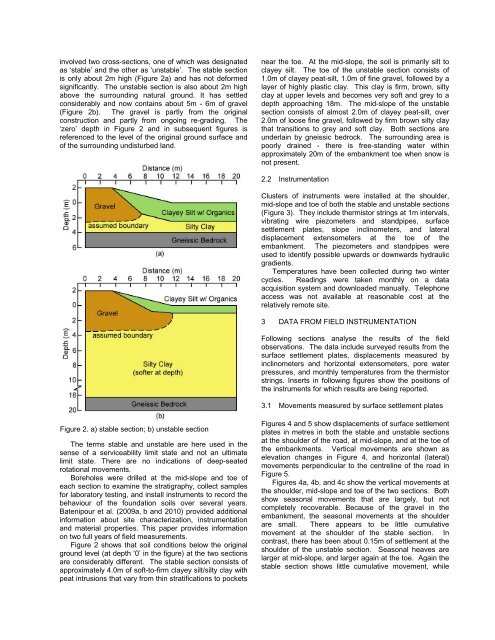
uildings and pipelines, airport runways, rail beds, and<str<strong>on</strong>g>highway</str<strong>on</strong>g> sub-bases, cuts and fills.Disc<strong>on</strong>tinuousPermafrostWinnipegPR391Thomps<strong>on</strong>ChurchillC<strong>on</strong>tinuous<strong>permafrost</strong>-1˚CFigure 1. Locati<strong>on</strong> <str<strong>on</strong>g>of</str<strong>on</strong>g> test site and <strong>permafrost</strong> in Manitoba,CanadaBecause the ice lenses are typically irregular inthickness and extent, out-migrati<strong>on</strong> <str<strong>on</strong>g>of</str<strong>on</strong>g> water <str<strong>on</strong>g>of</str<strong>on</strong>g>tenproduces differential settlements, lateral spreading, andreduced stability that lead to serviceability issues. .Typically, this thaw settlement is irregular (Hinkel et al.2003).Although the <strong>permafrost</strong> regi<strong>on</strong>s in northern Canadaare not heavily populated, their ec<strong>on</strong>omic importance hasincreased substantially in recent decades owing to thepresence <str<strong>on</strong>g>of</str<strong>on</strong>g> mineral, petrocarb<strong>on</strong> and hydroelectricresources. Thawing <str<strong>on</strong>g>of</str<strong>on</strong>g> summer ice in the Arctic Oceancan be expected to lead to additi<strong>on</strong>al shipping into the port<str<strong>on</strong>g>of</str<strong>on</strong>g> Churchill. New roads and railways will have to bec<strong>on</strong>structed into northern Manitoba and Nunavut oversoils with engineering properties that may degrade withclimate change and land-use. Design, c<strong>on</strong>structi<strong>on</strong>, andmaintenance <str<strong>on</strong>g>of</str<strong>on</strong>g> this new infrastructure will have to takeaccount <str<strong>on</strong>g>of</str<strong>on</strong>g> future warming (Hinkel et al. 2003).Figure 1 shows that Manitoba has disc<strong>on</strong>tinuous<strong>permafrost</strong> north <str<strong>on</strong>g>of</str<strong>on</strong>g> the isotherm for a current meanannual air temperature <str<strong>on</strong>g>of</str<strong>on</strong>g> about 0ºC (about 2500ºC-days<str<strong>on</strong>g>of</str<strong>on</strong>g> frost). The <strong>permafrost</strong> becomes c<strong>on</strong>tinuous furthernorth near the Huds<strong>on</strong> Bay coast.C<strong>on</strong>structi<strong>on</strong> in <strong>permafrost</strong> regi<strong>on</strong>s requires specialtechniques where soil pr<str<strong>on</strong>g>of</str<strong>on</strong>g>iles c<strong>on</strong>tain ice lenses.Disturbance <str<strong>on</strong>g>of</str<strong>on</strong>g> existing ground cover can change theenergy regime (Nels<strong>on</strong> and Outcalt, 1982). This <str<strong>on</strong>g>of</str<strong>on</strong>g>tenleads to thawing <str<strong>on</strong>g>of</str<strong>on</strong>g> underlying ice-rich <strong>permafrost</strong> andsubsidence <str<strong>on</strong>g>of</str<strong>on</strong>g> the road bed. <str<strong>on</strong>g>Deformati<strong>on</strong>s</str<strong>on</strong>g> can besufficiently large that the road becomes inoperable.Several methods are currently used to prevent orminimize thawing <str<strong>on</strong>g>of</str<strong>on</strong>g> <strong>permafrost</strong> and development <str<strong>on</strong>g>of</str<strong>on</strong>g>thermokarst. These include above-ground c<strong>on</strong>structi<strong>on</strong>,use <str<strong>on</strong>g>of</str<strong>on</strong>g> thermosyph<strong>on</strong>s, and buildings <strong>on</strong> piles or gravelpads above original ground level.Highway c<strong>on</strong>structi<strong>on</strong> in northern Canada followsbroadly similar practices to those in warmer regi<strong>on</strong>s. Fillsgenerally have high thermal c<strong>on</strong>ductivity, leading to heattransfer into underlying layers and thawing <str<strong>on</strong>g>of</str<strong>on</strong>g> previouslyfrozen foundati<strong>on</strong> soil (Batenipour et al. 2009b). Asphaltsurfacing absorbs heat from the sun and transfers it to the<str<strong>on</strong>g>embankment</str<strong>on</strong>g>. Generally, degradati<strong>on</strong> <str<strong>on</strong>g>of</str<strong>on</strong>g> <strong>permafrost</strong>begins at the toe <str<strong>on</strong>g>of</str<strong>on</strong>g> <str<strong>on</strong>g>embankment</str<strong>on</strong>g>s and extends laterbeneath the centre. Melting reduces strength andincreases pore water pressures when the hydraulicc<strong>on</strong>ductivity <str<strong>on</strong>g>of</str<strong>on</strong>g> the foundati<strong>on</strong> soil is low. This leads todifferential settlements, lateral spreading, and instability.In order to improve local design and maintenanceprocedures, Manitoba Infrastructure and Transportati<strong>on</strong>(MIT) and the University <str<strong>on</strong>g>of</str<strong>on</strong>g> Manitoba (UM) arecollaborating <strong>on</strong> several projects that involve fieldinstrumentati<strong>on</strong>, laboratory testing and numericalmodeling. This paper reports work <strong>on</strong> a project <strong>on</strong>Provincial Road PR391, about 18 km northwest <str<strong>on</strong>g>of</str<strong>on</strong>g>Thomps<strong>on</strong>, Manitoba (Figure 1). This is the <strong>on</strong>ly roadc<strong>on</strong>necting Thomps<strong>on</strong> to northern mining towns,hydroelectric generating stati<strong>on</strong>s, and first Nati<strong>on</strong>scommunities in north-western Manitoba. The site is in aregi<strong>on</strong> <str<strong>on</strong>g>of</str<strong>on</strong>g> disc<strong>on</strong>tinuous <strong>permafrost</strong>.2 GEOTECHNICAL SITE INVESTIGATIONS ANDFIELD INSTRUMENTATIONS2.1 Site Investigati<strong>on</strong>The PR391 was initially c<strong>on</strong>structed as a compactedearthen road <strong>on</strong> disc<strong>on</strong>tinuous <strong>permafrost</strong> in the mid-1960s and then c<strong>on</strong>verted to a gravel road in the early1970s. In the early 1980s, it was upgraded with abituminous pavement surface. Since c<strong>on</strong>structi<strong>on</strong>,changes in heat transfer have melted <strong>permafrost</strong> that hadbeen detected earlier, particularly under <str<strong>on</strong>g>embankment</str<strong>on</strong>g>s.Thawing led to large <strong>on</strong>going irregular deformati<strong>on</strong>s anddangerous traffic issues.Resp<strong>on</strong>ses by MIT included c<strong>on</strong>structi<strong>on</strong> <str<strong>on</strong>g>of</str<strong>on</strong>g> stabilizingberms and insulating peat berms beside the project<str<strong>on</strong>g>embankment</str<strong>on</strong>g> in the early 1990s. Over some years, theberms settled into the foundati<strong>on</strong> soil and essentiallydisappeared. They currently provide no additi<strong>on</strong>al supportto the original <str<strong>on</strong>g>embankment</str<strong>on</strong>g>. Regular maintenance hasadded several metres <str<strong>on</strong>g>of</str<strong>on</strong>g> gravel fill since initialc<strong>on</strong>structi<strong>on</strong>. Where extra maintenance is required, thewearing surface has been returned to gravel from asphalt:the asphalt pavement from the early 1980s has not beenreplaced.In 1991, drilling encountered frozen soil at depths from1.9m to 10.5m below the toe <str<strong>on</strong>g>of</str<strong>on</strong>g> the <str<strong>on</strong>g>embankment</str<strong>on</strong>g>. Laterdrilling in 2005, detected frozen soil at depths from 4.6mto 10.7m. Perhaps surprisingly, no frozen soil wasidentified in a recent drilling program in late 2008 usingc<strong>on</strong>tinuous flight, solid stem augers. A later secti<strong>on</strong> willshow no sub-zero temperatures below the active surfacelayer. C<strong>on</strong>siderable maintenance was required at the site.Records outlining maintenance procedures and annualapplicati<strong>on</strong> <str<strong>on</strong>g>of</str<strong>on</strong>g> gravel are unavailable.Figure 2 is the authors’ interpretati<strong>on</strong> <str<strong>on</strong>g>of</str<strong>on</strong>g> the results <str<strong>on</strong>g>of</str<strong>on</strong>g>the site investigati<strong>on</strong> at PR391 in 2008. The investigati<strong>on</strong>
involved two cross-secti<strong>on</strong>s, <strong>on</strong>e <str<strong>on</strong>g>of</str<strong>on</strong>g> which was designatedas ‘stable’ and the other as ‘unstable’. The stable secti<strong>on</strong>is <strong>on</strong>ly about 2m high (Figure 2a) and has not deformedsignificantly. The unstable secti<strong>on</strong> is also about 2m highabove the surrounding natural ground. It has settledc<strong>on</strong>siderably and now c<strong>on</strong>tains about 5m - 6m <str<strong>on</strong>g>of</str<strong>on</strong>g> gravel(Figure 2b). The gravel is partly from the originalc<strong>on</strong>structi<strong>on</strong> and partly from <strong>on</strong>going re-grading. The‘zero’ depth in Figure 2 and in subsequent figures isreferenced to the level <str<strong>on</strong>g>of</str<strong>on</strong>g> the original ground surface and<str<strong>on</strong>g>of</str<strong>on</strong>g> the surrounding undisturbed land.near the toe. At the mid-slope, the soil is primarily silt toclayey silt. The toe <str<strong>on</strong>g>of</str<strong>on</strong>g> the unstable secti<strong>on</strong> c<strong>on</strong>sists <str<strong>on</strong>g>of</str<strong>on</strong>g>1.0m <str<strong>on</strong>g>of</str<strong>on</strong>g> clayey peat-silt, 1.0m <str<strong>on</strong>g>of</str<strong>on</strong>g> fine gravel, followed by alayer <str<strong>on</strong>g>of</str<strong>on</strong>g> highly plastic clay. This clay is firm, brown, siltyclay at upper levels and becomes very s<str<strong>on</strong>g>of</str<strong>on</strong>g>t and grey to adepth approaching 18m. The mid-slope <str<strong>on</strong>g>of</str<strong>on</strong>g> the unstablesecti<strong>on</strong> c<strong>on</strong>sists <str<strong>on</strong>g>of</str<strong>on</strong>g> almost 2.0m <str<strong>on</strong>g>of</str<strong>on</strong>g> clayey peat-silt, over2.0m <str<strong>on</strong>g>of</str<strong>on</strong>g> loose fine gravel, followed by firm brown silty claythat transiti<strong>on</strong>s to grey and s<str<strong>on</strong>g>of</str<strong>on</strong>g>t clay. Both secti<strong>on</strong>s areunderlain by gneissic bedrock. The surrounding area ispoorly drained - there is free-standing water withinapproximately 20m <str<strong>on</strong>g>of</str<strong>on</strong>g> the <str<strong>on</strong>g>embankment</str<strong>on</strong>g> toe when snow isnot present.2.2 Instrumentati<strong>on</strong>Clusters <str<strong>on</strong>g>of</str<strong>on</strong>g> instruments were installed at the shoulder,mid-slope and toe <str<strong>on</strong>g>of</str<strong>on</strong>g> both the stable and unstable secti<strong>on</strong>s(Figure 3). They include thermistor strings at 1m intervals,vibrating wire piezometers and standpipes, surfacesettlement plates, slope inclinometers, and lateraldisplacement extensometers at the toe <str<strong>on</strong>g>of</str<strong>on</strong>g> the<str<strong>on</strong>g>embankment</str<strong>on</strong>g>. The piezometers and standpipes wereused to identify possible upwards or downwards hydraulicgradients.Temperatures have been collected during two wintercycles. Readings were taken m<strong>on</strong>thly <strong>on</strong> a dataacquisiti<strong>on</strong> system and downloaded manually. Teleph<strong>on</strong>eaccess was not available at reas<strong>on</strong>able cost at therelatively remote site.3 DATA FROM FIELD INSTRUMENTATIONFollowing secti<strong>on</strong>s analyse the results <str<strong>on</strong>g>of</str<strong>on</strong>g> the fieldobservati<strong>on</strong>s. The data include surveyed results from thesurface settlement plates, displacements measured byinclinometers and horiz<strong>on</strong>tal extensometers, pore waterpressures, and m<strong>on</strong>thly temperatures from the thermistorstrings. Inserts in following figures show the positi<strong>on</strong>s <str<strong>on</strong>g>of</str<strong>on</strong>g>the instruments for which results are being reported.3.1 Movements measured by surface settlement platesFigure 2. a) stable secti<strong>on</strong>; b) unstable secti<strong>on</strong>The terms stable and unstable are here used in thesense <str<strong>on</strong>g>of</str<strong>on</strong>g> a serviceability limit state and not an ultimatelimit state. There are no indicati<strong>on</strong>s <str<strong>on</strong>g>of</str<strong>on</strong>g> deep-seatedrotati<strong>on</strong>al movements.Boreholes were drilled at the mid-slope and toe <str<strong>on</strong>g>of</str<strong>on</strong>g>each secti<strong>on</strong> to examine the stratigraphy, collect samplesfor laboratory testing, and install instruments to record thebehaviour <str<strong>on</strong>g>of</str<strong>on</strong>g> the foundati<strong>on</strong> soils over several years.Batenipour et al. (2009a, b and 2010) provided additi<strong>on</strong>alinformati<strong>on</strong> about site characterizati<strong>on</strong>, instrumentati<strong>on</strong>and material properties. This paper provides informati<strong>on</strong><strong>on</strong> two full years <str<strong>on</strong>g>of</str<strong>on</strong>g> field measurements.Figure 2 shows that soil c<strong>on</strong>diti<strong>on</strong>s below the originalground level (at depth ‘0’ in the figure) at the two secti<strong>on</strong>sare c<strong>on</strong>siderably different. The stable secti<strong>on</strong> c<strong>on</strong>sists <str<strong>on</strong>g>of</str<strong>on</strong>g>approximately 4.0m <str<strong>on</strong>g>of</str<strong>on</strong>g> s<str<strong>on</strong>g>of</str<strong>on</strong>g>t-to-firm clayey silt/silty clay withpeat intrusi<strong>on</strong>s that vary from thin stratificati<strong>on</strong>s to pocketsFigures 4 and 5 show displacements <str<strong>on</strong>g>of</str<strong>on</strong>g> surface settlementplates in metres in both the stable and unstable secti<strong>on</strong>sat the shoulder <str<strong>on</strong>g>of</str<strong>on</strong>g> the road, at mid-slope, and at the toe <str<strong>on</strong>g>of</str<strong>on</strong>g>the <str<strong>on</strong>g>embankment</str<strong>on</strong>g>s. Vertical movements are shown aselevati<strong>on</strong> changes in Figure 4, and horiz<strong>on</strong>tal (lateral)movements perpendicular to the centreline <str<strong>on</strong>g>of</str<strong>on</strong>g> the road inFigure 5.Figures 4a, 4b, and 4c show the vertical movements atthe shoulder, mid-slope and toe <str<strong>on</strong>g>of</str<strong>on</strong>g> the two secti<strong>on</strong>s. Bothshow seas<strong>on</strong>al movements that are largely, but notcompletely recoverable. Because <str<strong>on</strong>g>of</str<strong>on</strong>g> the gravel in the<str<strong>on</strong>g>embankment</str<strong>on</strong>g>, the seas<strong>on</strong>al movements at the shoulderare small. There appears to be little cumulativemovement at the shoulder <str<strong>on</strong>g>of</str<strong>on</strong>g> the stable secti<strong>on</strong>. Inc<strong>on</strong>trast, there has been about 0.15m <str<strong>on</strong>g>of</str<strong>on</strong>g> settlement at theshoulder <str<strong>on</strong>g>of</str<strong>on</strong>g> the unstable secti<strong>on</strong>. Seas<strong>on</strong>al heaves arelarger at mid-slope, and larger again at the toe. Again thestable secti<strong>on</strong> shows little cumulative movement, while