ALUSIL ® -Cylinder Blocks Porsche V6/V8 - KSPG AG
ALUSIL ® -Cylinder Blocks Porsche V6/V8 - KSPG AG
ALUSIL ® -Cylinder Blocks Porsche V6/V8 - KSPG AG

Create successful ePaper yourself
Turn your PDF publications into a flip-book with our unique Google optimized e-Paper software.
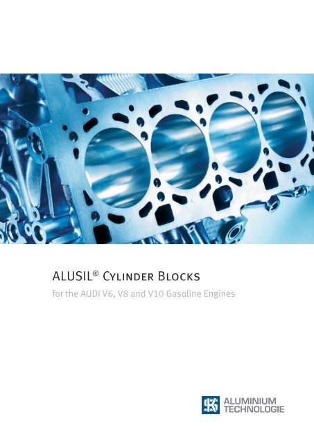
<strong>ALUSIL</strong> <strong>®</strong> <strong>Cylinder</strong> <strong>Blocks</strong><br />
for the AUDI <strong>V6</strong>, <strong>V8</strong> and V10 Gasoline Engines
1. Audi setting standards in lightweight design<br />
With its vehicle model series, Audi is setting new standards<br />
in lightweight design. So it is only logical for the carmaker<br />
again to count on aluminium in developing the cylinder<br />
blocks for its actual gasoline V-engines (Fig. 1). On account<br />
of the reduced wall thickness (cylinder land width of only<br />
5.5 mm (Fig. 2) between cylinder bores), Audi relies on the<br />
hypereutectic aluminium-silicon alloy AlSi17Cu4Mg registered<br />
for KS Aluminium-Technologie under the brand name<br />
of <strong>ALUSIL</strong> <strong>®</strong> . This concept allows the pistons to move directly<br />
<strong>V6</strong> cylinder block<br />
<strong>V8</strong> cylinder block<br />
(multi-point injection)<br />
Fig. 1: <strong>ALUSIL</strong> <strong>®</strong> cylinder block of the Audi <strong>V6</strong>, <strong>V8</strong> and V10 gasoline engine generation<br />
along the honed cylinder bore surfaces of the aluminium<br />
casting – an ideal condition for compact high-performing<br />
engines.<br />
2. Reasons in favor of <strong>ALUSIL</strong> <strong>®</strong> from the viewpoint<br />
of Audi:<br />
There are many technical reasons which induced the carmaker<br />
Audi to adhere to the proven <strong>ALUSIL</strong> <strong>®</strong> concept:<br />
<strong>V8</strong> cylinder block<br />
(fuel stratified injection [FSI])<br />
V10 cylinder block<br />
3
4<br />
5.5 mm<br />
Fig. 2: <strong>Cylinder</strong> head flange surface with a land width of only<br />
5.5 mm<br />
Fig. 3: Material structure of the alloy AlSi17Cu4Mg / <strong>ALUSIL</strong> <strong>®</strong><br />
with primarily precipitated silicon crystals (dark areas in the<br />
picture)<br />
Fig. 4: Mechanically exposed <strong>ALUSIL</strong> <strong>®</strong> cylinder bore surface<br />
<strong>ALUSIL</strong> <strong>®</strong> makes a minimum weight at a high degree of integration<br />
of engine functions like lubricant, coolant and<br />
engine venting circuits.<br />
<strong>ALUSIL</strong> <strong>®</strong> enables minimum overall cylinder block lengths<br />
to be implemented because the engines can be operated<br />
without inserted cylinder liners. To achieve the shortest<br />
possible engine length at a specified swept volume and<br />
stroke, the cylinder bore diameter should be kept as large<br />
as possible, at minimum land width. In such cases, the<br />
land width of the jointly cast cylinders is determined in<br />
practice by the safe and reliable performance of the cylinder<br />
head gasket, by the cutting pressure applied for machining<br />
and the cylinder distortion in engine operation.<br />
<strong>ALUSIL</strong> <strong>®</strong> boasts excellent tribological characteristics. As<br />
the pistons and piston rings slide along the exposed silicon<br />
crystals, their susceptibility to seizing is minimized<br />
(Fig. 3).<br />
<strong>ALUSIL</strong> <strong>®</strong> displays optimum thermal conductivity; Audi is<br />
thus in a position to achieve a high specific engine performance.<br />
<strong>ALUSIL</strong> <strong>®</strong> does not imply any recycling problems because<br />
the cylinder block does not contain extraneous materials<br />
– such as cast-in cylinder liners made of grey cast iron.<br />
<strong>ALUSIL</strong> <strong>®</strong> allows cylinder blocks to be cast monolithically<br />
without cylinder liners or subsequent coating of the cylinder<br />
bores. This makes it possible to achieve:<br />
components of optimum structural rigidity through<br />
the benefit of a by 12 % higher Young’s modulus of the<br />
<strong>ALUSIL</strong> <strong>®</strong> alloy compared to a hypoeutectic standard<br />
alloy as well as,<br />
process reliability in machining without having to interrupt<br />
the process flow for costly additional working<br />
steps specifically for the cylinder bore surfaces. A decisive<br />
milestone in this area was the mechanical exposure<br />
of the silicon crystals by means of a third honing<br />
step (Fig. 4) as a substitute for the chemical laying<br />
bare (etching) after the two-step honing process which<br />
was a must before. Laying bare the silicon grains by<br />
mechanical means allows perfect on-line production.
The above described assets of the <strong>ALUSIL</strong> <strong>®</strong> alloy are certainly<br />
significant arguments in favor of the use of this material.<br />
But also the low-pressure die casting method (Fig. 5) which<br />
has since then proven to be the best by far is an important<br />
prerequisite for process reliability in making mass-produced<br />
cylinder block castings of <strong>ALUSIL</strong> <strong>®</strong> .<br />
3. Reasons in favor of low-pressure die casting from<br />
the viewpoint of Audi:<br />
Low-pressure die casting, LPDC (Figs. 5 – 6) allows to use<br />
sand cores where necessary, e.g. for water jackets (Fig. 7).<br />
In this way, structurally rigid closed-deck cylinder blocks<br />
can be produced, a prerequisite for high specific engine<br />
outputs.<br />
LPDC allows controlled, low-turbulence die filling, and<br />
what is even more important, controlled cooling of the die<br />
to ensure component-specific, virtually ideal directional<br />
solidification. The compilation of all casting-relevant data<br />
and the resulting control of the casting process are implemented<br />
today computer-assisted. Especially a purposedesigned<br />
cylinder sleeve cooling system is an indispensable<br />
prerequisite for uniform precipitation of the silicon<br />
crystals in the cylinder area (criteria: distribution, grain<br />
size range (Fig. 8) and number of crystals per cm²), low<br />
porosity and minimizing casting defects like shrinkage<br />
holes, pores, cold fusion, etc. This process control ensures<br />
constant quality of the castings.<br />
LPDC permits unrestricted heat treatment of the casting.<br />
It is already possible to achieve a certain increase in hardness<br />
and strength by applying controlled cooling of the<br />
cylinder blocks from the casting temperature by means<br />
of customary T5 heat treatment. The subsequent artificial<br />
aging not only serves to enhance hardness and strength,<br />
but primarily also to stabilize the volume, i.e. avoid an<br />
irreversible expansion in length and volume (distortion)<br />
referred to as “growth” when the casting is exposed to<br />
the operating temperature of the engine.<br />
To cope with even higher engine stresses, a modified T5<br />
heat treatment solution is available where the hardness and<br />
strength of the components are enhanced through the casting<br />
heat, e.g. locally in the cylinder deck or bearing bulkhead<br />
area by means of chilling with water which leads to precipitation<br />
hardening.<br />
Sleeve yoke with<br />
movable die half<br />
Open die<br />
Stationary<br />
die half<br />
Crucible<br />
with melt<br />
(holding<br />
furnace)<br />
<strong>Cylinder</strong> sleeves<br />
Casting<br />
Lifting table,<br />
stroke about 2 m<br />
Hydraulic cylinder<br />
sleeve lifters<br />
Hydraulic<br />
lateral slides<br />
Feed tube<br />
Fig. 5: Low-pressure die casting, illustrated principle of a casting<br />
cell with opened die (movable die half in lifted position)<br />
Fig. 6: Design of a low-pressure die for aluminium cylinder<br />
block<br />
5
For absolute high-performance engines, Audi applies full<br />
heat treatment (T6) comprising homogenizing, chilling and<br />
artificial aging. This method contributes to a further distinct<br />
improvement in terms of static and dynamic strength. As the<br />
T6 heat treatment without specific artificial ageing only contributes<br />
little to volume stabilisation, but implies the risk of<br />
distortion in engine operation, the artificial ageing process<br />
is stretched in the T7 heat treatment mode, thus increasing<br />
extension.<br />
4. Audi’s V-engine generation<br />
The V-engine generation of Audi – both petrol and diesel<br />
engines – is setting standards with respect to compactness<br />
and overall length. Customers’ requests for more powerful<br />
engines even in smaller vehicle model series implied the<br />
need for shorter overall engine lengths and for reducing the<br />
vehicle front-part weight. As a result the current V-engine<br />
generation has been created.<br />
6<br />
Audi is the market leader in lightweight design, specifically<br />
in the premium segment. The lightweight strategy is impressively<br />
implemented in the car body through the Audi space<br />
frame aluminium technology. It was a logical consequence<br />
therefore to rely on a weight-optimizing all-aluminium solution<br />
for the petrol V engines – i.e. <strong>ALUSIL</strong> <strong>®</strong> cylinder blocks.<br />
5. The Audi <strong>V6</strong>, <strong>V8</strong> and V10 gasoline engine concept<br />
The <strong>V6</strong> in the large displacement version of 3.2 l, the <strong>V8</strong> with<br />
a swept volume of 4.2 l as well as V10 of 5.2 l swept volume<br />
originate from the current Audi-V engine family with a stroke<br />
of 92.8 mm (Fig. 9a and 9b ), a V angle of the cylinder banks<br />
of 90° and a central division of the cylinder block (bedplate<br />
concept). The distance between cylinders is 90 mm, the cylinder<br />
bank offset being 18.5 mm. For the <strong>V6</strong> of 3.2 l swept<br />
volume, the <strong>V8</strong> of 4.2 l and the V10 of 5.2 l displacement,<br />
the cylinder bore is 84.5 mm. It is 81 mm in the case of the<br />
Fig. 7: View of a water-jacket core box in the core shooter: water-jacket sand cores for Audi <strong>V6</strong> cylinder block (left) and <strong>V8</strong> cylinder block<br />
(right)
smaller <strong>V6</strong> engine with a swept volume of 2.4 l. The cylinders<br />
are cast jointly, at a cylinder land width of 5.5 mm or, respectively,<br />
9 mm for the smaller <strong>V6</strong>.<br />
The <strong>V6</strong> engine in the large swept-volume version is operated<br />
with fuel stratified injection (FSI) and with compressor supercharging<br />
for optimised charge air cycles with TFSI. The smaller<br />
swept-volume version is still designed for multi-point injection<br />
(MPI). The different cylinder bore dimensions do not<br />
require adjustment on the water jacket side, and this allowed<br />
implementing a low-cost concept. The <strong>V8</strong> and V10 gasoline<br />
engines are likewise available in two versions. A new engine<br />
version with bi-turbo charging has been added to the series,<br />
which also distinguishes itself in the cylinder block.<br />
6. Description of the cylinder block top<br />
As mentioned above, the Audi cylinder blocks (Fig. 10) are<br />
made of the hypereutectic alloy AlSi17Cu4Mg. The low-pressure<br />
die casting method is applied, with controlled cooling<br />
from the casting temperature. Cooling takes place at ambient<br />
air or its partly assisted by an air blower. This is followed by<br />
Number of grains in the area measured<br />
25.0<br />
20.0<br />
15.0<br />
10.0<br />
5.0<br />
0<br />
10 20 30 40 50 60 70 80<br />
Grain size [µm]<br />
Fig. 8: Representative grain distribution of the primarily precipitated silicon crystals<br />
artificial aging for volume stabilizing (T5 heat treatment), a<br />
process which only implies a slight decrease in hardness. The<br />
associated bedplates – not included in the scope of supply<br />
of KS Aluminium-Technologie – are high-pressure die castings<br />
made from the hypoeutectic alloy AlSi9Cu3 with castin<br />
bearing bulkheads of nodular cast iron. The bedplates of<br />
the <strong>V8</strong> and V10 engines are made from alloy AlSi12Cu1(Fe).<br />
The cylinder blocks of the <strong>V8</strong> FSI, of the V10 FSI as well as<br />
the V10 bi-turbo were subjected to structural optimisation<br />
to account for increased performance output. Externally, this<br />
is visible at the cross members in the V space between the<br />
cylinder banks. Further modifications relate to the oil filter<br />
flange area.<br />
The water jackets of the cylinder banks produced by using<br />
sand cores as well as the water supply channels are integrated<br />
on the left and right sides in the cylinder blocks. In the<br />
case of the <strong>V6</strong>, in addition the part of the water pump housing<br />
on the discharge-nozzle side is arranged at the front,<br />
above the V space but connected with it. Water supply to the<br />
jackets of the two cylinder banks is accomplished by means<br />
of a manifold, flange-mounted in the V space.<br />
Area measured<br />
7
Whereas in the standard FSI engines the cooling water flows<br />
around the cylinders from the front to the rear, in the case of<br />
the V10 bi-turbo a cross-flow principle has been implemented.<br />
Thanks to forced flow, the cooling effect is enhanced in<br />
both the cylinder block and the cylinder head.<br />
The oil circuit ducts are partly pre-cast, partly drilled. The<br />
two deep-hole bores centrally arranged in the V, for the main<br />
oil and injection nozzle channels for piston cooling, which<br />
virtually cover the whole block length, are machined at KS<br />
Aluminium-Technologie. The non-pressurized oil drain backs<br />
and cylinder block vent ducts are pre-cast for the <strong>V8</strong> and V10<br />
cylinder blocks. They are arranged externally on the side<br />
walls, in parallel with the cylinders. These channels are connected<br />
with the bedplate through bores in order to exclude<br />
the risk of casting fins being left.<br />
Subsequently, after removing the sand cores, the cylinder<br />
blocks are submitted to first cut machining (Fig. 11).<br />
Adjustment in the crankcase area is achieved by alignment<br />
in the first clamping step, starting from cast locating points<br />
at the interface to the bedplate. To this effect, the three locating<br />
points on the gearbox side are machined and two index<br />
bores (fitting bores) are set.<br />
8<br />
Fig. 9a : The Audi <strong>V6</strong> gasoline engine<br />
Further machining steps in the first and second clamping operations<br />
are the drilling of the oil ducts, pre-drilling of the<br />
cylinders, pre-milling of the main bearing area and cubing of<br />
the external faces. In this last step, all “important” surfaces<br />
are re-milled in order to remove casting fins, for instance, in<br />
order to enable a process-reliable leak test to be carried out<br />
subsequently.<br />
To ensure proper casting quality, the cylinder blocks are<br />
submitted to comprehensive x-ray, hardness and ultrasonic<br />
tests. The latter serves to check the bearing bulkheads for<br />
porosity. The oil and water systems are checked for leaks by<br />
means of a differential pressure test, followed by a 100% visual<br />
inspection before the cylinder blocks are dispatched to<br />
Audi on purpose-designed loading devices.<br />
At AUDI HUNGARIA MOTOR Kft. (AHM), the cylinder blocks<br />
are integrated into the machining line on the locating points<br />
and aligned on gearbox flange level by means of the fitting<br />
bores provided in the gearbox flange. Next, the cylinder<br />
block is machined as an individual part, with most of the<br />
machining work being done in these working steps. Subsequently,<br />
the finished bedplate is “matched” with the cylinder<br />
block, i.e. pinned and bolted. From this moment, the cylinder
lock and the bedplate constitute one unit and move jointly<br />
through the assembly line. An important machining step is<br />
the mechanical exposure of the silicon crystals in a third<br />
honing step with “soft” honing stones which means honing<br />
with cutting material embedded in a non-rigid matrix.<br />
The third honing run, i.e. finish honing, is accomplished using<br />
elastic honing stones – made of corundum or SiC grains<br />
in a porous plastic bond – whose cutting grains rebounce on<br />
contact with the hard silicon grains so that they remove more<br />
of the aluminium matrix than of the silicon grains. Compared<br />
to a conventionally honed grey casting bore surface, this<br />
three-step honing operation results in a relatively smooth<br />
bore surface (Fig. 4) which has a favourable effect on oil consumption<br />
(hydrocarbon emissions), friction losses and wear<br />
of the contact partners (piston and piston rings).<br />
<strong>ALUSIL</strong> <strong>®</strong> features sufficiently high strength so that even for<br />
the high-strength bolt joints like those of main bearing cap<br />
and cylinder head the nut thread can be cut directly into<br />
the cast material. When “overtightening” the bolt, it will invariably<br />
tear off before the nut threads are shorn. The high<br />
compressive strength of <strong>ALUSIL</strong> <strong>®</strong> has an extremely positive<br />
effect on the bolted joints. It exceeds the tensile strength by<br />
Fig. 9b : The Audi <strong>V8</strong> gasoline engine<br />
Fig. 10: Aluminium cylinder block concept, consisting of<br />
monolithic cylinder block top and bedplate with cast-in<br />
bearing bulkheads made of spheroidal casting<br />
9
nearly 100 %, depending on the heat treatment condition. As<br />
a result, commercial bolt heads hardly lead to an appreciable<br />
setting of the aluminium even if the bolt was tightened up to<br />
the tensile yield point.<br />
7. Description of the casting die and development/adjustment<br />
of the casting process<br />
The synergy effect envisioned by Audi when changing from<br />
the <strong>V6</strong> to the V10 cylinder blocks was fully achieved in terms<br />
of casting tool design, conceptual design of the machining<br />
equipment and test devices and, in particular, the development<br />
and adjustment of the casting process. Thanks to sustainable<br />
exploitation of all possibilities of virtual product and<br />
Fig. 11: Solidification simulation with the example of the <strong>V6</strong> cylinder block<br />
Top: Residual solidification zone (risk of blowholes) in the gearbox flange area without active cooling measures<br />
Bottom: Optimized condition; avoidance of blowholes (no residual solidification zones) through selective active cooling measures<br />
10<br />
Critical residual solidification zone<br />
process development based on a consistent CAD, CAE, CAM<br />
line (Figs. 11, 12), the targeted effective optimisation of the<br />
cylinder blocks was accomplished.<br />
8. Summary, conclusion and outlook<br />
For its state-of-the-art high-performance gasoline engines of<br />
V design, Audi stakes on the combination of <strong>ALUSIL</strong> <strong>®</strong> lowpressure<br />
die casting and mechanical silicon grain exposure.<br />
In the present situation, this combination offers optimum<br />
conditions for the engine functions, production and process<br />
reliability as well as quality. Hence there are quite a number<br />
of factors speaking in favor of <strong>ALUSIL</strong> <strong>®</strong> to be rated as one of<br />
the best materials available today for high-performance gas-
oline V engines when weighing the many convincing positive<br />
properties up against occasionally adduced less favourable<br />
characteristics like low ductility and the somewhat higher<br />
machining costs. What is a decisive aspect is the potential it<br />
implies for further strength improvements through full hardening<br />
heat treatment (T6) the entire component or local, socalled<br />
modified T5 heat treatment.<br />
KS Aluminium-Technologie has pursued for decades the continuous<br />
optimisation of the <strong>ALUSIL</strong> <strong>®</strong> concept. This includes<br />
the relevant further development of the low-pressure die<br />
casting process which has been fully integrated. Manufacturers<br />
favouring the respective technologies, be it the conventional<br />
or the future-oriented one, appreciate the qualitative<br />
advantages of this casting process. Of late, the low-pressure<br />
1a<br />
1b<br />
2a<br />
2b<br />
Fig. 12: Die filling simulation of the gearbox flange with the example of the <strong>V8</strong> cylinder block<br />
Top (pictures 1a -3a): turbulent filling (surging melt due to abrupt cross-sectional change)<br />
Bottom (pictures 1b -3b): stabilized filling by adjusting the geometry and optimum filling parameters<br />
die casting process has been gaining further in importance<br />
because it offers the possibility to fully exploit the strength<br />
potential of the material by artificial ageing in connection<br />
with the development of passenger car engines which are<br />
subjected to ever higher stresses. By casting in sand cores,<br />
further functions can be integrated into the component and<br />
additional lightweight construction potential is generated.<br />
3a<br />
3b<br />
11
KS Aluminium-Technologie GmbH · Hafenstraße 25 · 74172 Neckarsulm · GERMANY<br />
Tel. +49 7132 33-1 · Fax +49 7132 33-4357 · www.kspg.com<br />
Subject to alterations. Printed in Germany. A|IX|k<br />
5
![PDF [1.0 MB] - KSPG AG](https://img.yumpu.com/5513074/1/171x260/pdf-10-mb-kspg-ag.jpg?quality=85)