6900 PowerMatic ® Low Energy Power Operator Wiring Instructions ...
6900 PowerMatic ® Low Energy Power Operator Wiring Instructions ...
6900 PowerMatic ® Low Energy Power Operator Wiring Instructions ...

Create successful ePaper yourself
Turn your PDF publications into a flip-book with our unique Google optimized e-Paper software.
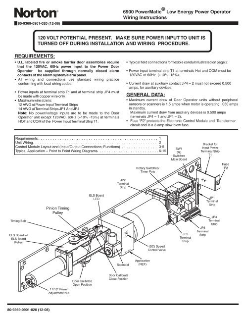
80-9369-0901-020 (12-08)<strong>6900</strong> <strong><strong>Power</strong>Matic</strong> <strong>®</strong> <strong>Low</strong> <strong>Energy</strong> <strong>Power</strong> <strong>Operator</strong><strong>Wiring</strong> <strong>Instructions</strong>120 VOLT POTENTIAL PRESENT. MAKE SURE POWER INPUT TO UNIT ISTURNED OFF DURING INSTALLATION AND WIRING PROCEDURE.REQUIREMENTS:• U.L. labeled fire or smoke barrier door assemblies requirethat the 120VAC, 60Hz power input to the <strong>Power</strong> Door<strong>Operator</strong> be supplied through normally closed alarmcontacts of the alarm system/alarm panel.• All wiring and connections use standard wiring practiceconforming with local wiring codes.• <strong>Power</strong> inputs at terminal strip T1 and at terminal strip JP4 mustbe made with copper wire only.• Maximum wire size is:12 AWG at <strong>Power</strong> InputTerminal Strips14 AWG atTerminal Strips JP1 And JP4Note: No power/voltage inputs are to be made to the Door<strong>Operator</strong> unit except 120VAC, 60Hz (+10% -15%) at terminalsHOT and COM of the <strong>Power</strong> InputTerminal StripT1.• Typical field connections for flexible conduit illustrated on page 2.• <strong>Power</strong> input terminal strip T1 at terminals Hot and COM must be120VAC at 60Hz (+10% -15%).• Current draw at auxiliary contact JP4 – 2 must not exceed 0.500amps, for auxiliary devices.GENERAL DATA:• Maximum current draw of Door <strong>Operator</strong> units without peripheralsensors or scanners is 1.5 amps when motor is operating, .050 ampsin standby.Maximum current draw from auxiliary devices is 0.500 amps(terminals JP4 – 1 and JP4 – 2).• Fuse “F2” protects the Electronic Control Module and Transformercircuit and is a 3 amp slow blow fuse.RequirementsUnit <strong>Wiring</strong>Control Module Layout and (Input/Output Connections; Functions)Typical Application – Point to Point <strong>Wiring</strong> DiagramsRotary Switches/Timer Pots123-56-15SW1DipSwitchesMain BoardBracket forInput <strong>Power</strong>Terminal StripT1FuseF2JP2TerminalStripTiming BeltELS Board w/ELS BoardPulleyPinion TimingPulleyELS BoardLEDSCPUSH(SC) SpeedControl ValveJP3TerminalStripJP1TerminalStripJP4TerminalStripJP5TerminalStripSolenoidApplication(REF)11/16" <strong>Power</strong>Adjustment NutDoor CalibrateOpen PositionDoor CalibrateClose Position80-9369-0901-020 (12-08)
5678901234567890123456789012345678901234SW5 RotarySwitch/TimerPotSW4 RotarySwitch/TimerPotSW2 RotarySwitch/TimerPotSW1 DipSwitchesJP1 TerminalStripJP2 TerminalStripSW3 RotarySwitch/TimerPotJP3 TerminalStripFuse F11.5 amp,2AGSlo-BloG E M G H +V L2 G L1 MOTOR/SOLENOIDJP3JP2CL/AS DLY VEST DLYEXSOL DLYRelayK2M. DLYRelayK16600/6700 SERIES DOOR OPERATOR41-6700-0056 REV A MADE IN USASW1OFF ONP/AA/DRES1RES2NEU HOT GNDJP518VACRelayK3RelayK41 2 3 4 5 6 7 8GND +24V NO1 CO1 NC1 NO2 CO2 NC2JP4JP114131211109876543210/0 RES1 AUX2 GND INV OUTV GND RFT GND AUX2 GND PDET GND AUX1JP4 TerminalStripElectronic Control Module (Main PC Board)JP1 Terminal Strip – Maximum wire size 14AWG. For signaling only, do not make power input connections.TERMINALD E S CRIPTION1 0/0Override Open – This terminal has two possible functions that can be used together or separately.1. Smoke Ventilation Door or Blow Open Door – Upon initiation of a closed signal from a fire/ smoke alarmpanel, door will open and remain open until signal is terminated. Use with any JP1 ground.2. Alarm Delay (30 second or 60 second time period) – Time is set with dip switch SW1 – 2 A/D. (OFF = 30second delay, ON = 60 second delay) Use with any JP1 ground.2 RES1 This is not an active contact.3 AUX24 GND Ground5 INV6 OUTV7 GND GroundAuxiliary 2 – This is one of two secondary initiating switch contacts (JP1 – 10 is the other.)For most applications it is equivalent to AUX1 JP1 – 14. For Vestibule Function use, it is the contact for a switchlocated within the vestibule. Use with any JP1 ground.In Vestibule – Used for Vestibule Function. This contact must be connected to the JP1 – 6 terminal from anotherunit to receive an initiating signal. The signal is then programed to initiate the unit by setting the VEST DLY rotaryswitch/timer pot of the receiving unit. Use this contact with any JP1 ground.Out Vestibule – Used for Vestibule Function. This contact must be connecter to terminal JP1 – 5 of another unit tosend an initiating signal. Use with any JP1 ground.8 RFTMaintain Hold Open – With the unit’s 3 Position Slide Switch in the “ON” position, a signal will open the door andmaintain an indefinite hold open until a second signal releases the door from hold open. Use with any JP1 ground.This feature recommended for <strong>Power</strong> <strong>Operator</strong> Function. If using with the <strong>Power</strong> Assist Function, consult factory.9 GND Ground10 AUX2 Auxiliary 2 – Same as JP1 – 3 / AUX2 above.11 GND Ground12 PDET13 GND Ground14 AUX1Presence Detector – Permits wiring of a presence detector to prevent a closed door from opening or a door that isfully open from closing. Use with any JP1 ground.Auxiliary 1 – Primary initiating switch contact. Initiates door power cycle. For Vestibule Function, the switch atoutside of vestibule is connected to this terminal. (Outside switch to outside unit’s JP1 – 14. Inside switch to insideunit’s JP1 – 14). Use with any JP1 ground.80-9369-0901-020 (12-08) 3
JP4 Terminal Strip – Maximum wire size 14AWG.TERMINALD E S CRIPTION1 GND Ground2 +24 24VDC output to a maximum current draw of 0.500 amps. Use with ground terminal JP4 – 13 NO1Solenoid Control (Relay Contact Only) – Normally open contact that is switched by Relay K3 (on main board) toclose. Relay K3 will remain switched for a period set by SW – 3 EXSOL DLY rotary switch / timer pot. Use withterminal JP4 – 4 CO1. Coordinate use of this terminal with delayed start of motor using rotary timer pot SW – 2 M4 CO1 Solenoid Control (Relay Contact Only) – Common contact for use with terminals JP4 – 3 NO1 and JP4 - 5 NC1.5 NC16 NO2Solenoid Control (Relay Contact Only) – Normally closed contact that is switched by Relay K3 (on main board) toopen. Relay K3 will remain switched for a period set by SW – 3 EXSOL DLY rotary switch / timer pot. Use withterminal JP4 – 4 CO1. Coordinate use of this terminal with delayed start of motor using rotary timer pot SW – 2 MDLY.Alarm Delay (Switching Contact Only) – Normally open contact that is switched by relay K4 (on main board) toclose. Relay K4 will remain switched for a period set by Dip Switch SW1 – 2 A/D (OFF = 30 second delay; ON = 60second delay). Use with terminal JP4 – 7 CO2.7 CO2 Alarm Delay (Switching Contact Only) – Common contact for use with terminals JP4 – 6 NO2 and JP4 – 8 NC2.8 NC2Alarm Delay (Switching Contact Only) – Normally closed contact that is switched by relay K4 (on main board) toopen. Relay K4 will remain switched for a period set by Dip Switch SW1 – 2 A/D (OFF = 30 second delay; ON = 60second delay). Use with terminal JP4 – 7 CO2.Main Board SwitchesDIP SWITCHES (MAIN BOARD)1 P/ADESCRIPTIONDoor <strong>Operator</strong> Function Switch – OFF position selects the <strong>Power</strong> <strong>Operator</strong> Function. Onposition sets the <strong>Power</strong> Assist Function.2 A/DAlarm System Delay Timer – This switch is used in conjunction with terminal Jp1– 1, 0/0 foroptional function 2. (OFF = 30 second delay, ON = 60 second delay).3 RES1 DIAGNOSTIC USE. FOR FACTORY AUTHORIZED PERSONAL.4 RES2 DIAGNOSTIC USE. FOR FACTORY AUTHORIZED PERSONAL.ROTARY SWITCHESSW2M DLYSW3 EXSOL DLYSW4 VEST DLYSW5 CL/AS DLYDESCRIPTIONThis rotary switch or timer pot sets the length of delay for motor start up to allow for “unlocking”of exit devices, electric strikes, magnetic locks, etc. See Chart 1 for delay times.This rotary switch or timer pot sets the length of time that a solenoid remains either energized orde-energized to allow “unlocking”. Used in conjunction with terminals JP4 – 3, JP4 – 4, JP5 – 5.See Chart 2 for length of time.This switch or timer pot sets the length of time between receipt of the “In Vestibule” signal(terminal JP1 – 5) and motor start-up. See Chart 3 for delay times.Controls either one of two function times:<strong>Power</strong> <strong>Operator</strong> Function – Sets length of time door holds open at fully “taught” open position.<strong>Power</strong> Assist Function – Sets length of time motor and pump will operate to reduce openingforce. When time elapses, the door force reverts to full opening spring force set.Chart 1 – SW2, M DLYLength of TimeSettings(Seconds)0.000.210.521.031.542.553.564.57Chart 2 – SW3, EXSOL DLYLength of TimeSettings(Seconds)001122436485106127Chart 3 – SW4, VEST DLYLength of Time(Seconds)01369142130Settings01234567Chart 4 – SW5, CL/AS DLYLength of TimeSettings(Seconds)002152103154205256307480-9369-0901-020 (12-08)
JP2 Terminal Strip – Factory Wired Connections.TERMINALD E S CRIPTIONL1GL2White Wire – High side of L1 Input signal from ELS Board. Detects door motion to open door when door is pushedor pulled in the open direction. Movement of potentiometer on ELS Board signals L1 input.Black Wire – Ground. Common connection for L1 and L2 inputs.Blue Wire – High side of L2 Input signal for ELS Board. Detects the Fully Open Position stored in the ELS Boardduring the teaching mode.+V Yellow Wire +24VDC. This terminal is used to supply power to the ELS Board.HGMEGViolet Wire – Hold Open contact of “OFF” “ON” “H/O” switch assembly.White Wire – Ground. Common contact of “OFF” “ON” “H/O” switch assembly.Orange Wire – ON contact of “OFF” “ON” “H/O” switch assembly.Red Wire – Emergency Hold Open Release. This contact is used in conjunction with the ELS board to close thedoor immediately at any point of door opening once an obstruction on opening is encountered. It is used withterminal JP2 – G.Black Wire – Ground. Use with terminal Jp2 – E for Emergency Hold Open Release.JP5 Terminal Strip – Factory Wired Connections.TERMINALD E S CRIPTION1 NEU Common 120V connection to Input <strong>Power</strong> Terminal 22.2 HOT Hot 120V connection to Input <strong>Power</strong> Terminal 24.3 GNDGround connection secured to backplate under head of (green) ground screw that is located under Main PC Board.Screw Labeled “GND”4 18VAC From secondary of 120V / 24V transformer.5 18VAC From secondary of 120V / 24V transformer.JP3 Terminal Strip – Factory Wired Connections.TERMINALMOTORSOLENOIDMotor Connection.Solenoid coil connection.D E S CRIPTION80-9369-0901-020 (12-08) 5
56789012345678901234567890123456789012340/0 RES1 AUX2 GND INV OUTV GND RFT GND AUX2 GND PDET GND AUX10/0 RES1 AUX2 GND INV OUTV GND RFT GND AUX2 GND PDET GND AUX1Standard Function with SwitchesOperation:Doors are normally closed.Activating either switch will open both doors. Door willclose after hold open time delay has elapsed.Wall Switch, CardReader, Key Switch,etc.Normally Open Momentarydry contactsG E M G H +V L2 G L1 MOTOR/SOLENOIDJP3JP2CL/AS DLY VEST DLYEXSOL DLY M. DLYNEU HOT GNDJP518VACSW1OFF ONP/AA/DRES1RES2JP1141312111098765432112345678910111213141 2 3 4 5 6 7 8GND +24V NO1 CO1 NC1 NO2 CO2 NC2JP4JP1Door 1 Door 2RELAY CONTACTS FORELECTRIC STRIKE.ELECTRIC LATCH RETRACTEXIT DEVICE, MAGNETICLOCK, ETC.Wall Switch, CardSee Note 3.Reader, Key Switch,etc.Normally Open Momentarydry contactsNote 3:If product being connected doesnot have an integrated diode, onemust be installed across contractsto protect relays . Suggested diode is1N4001 or equivalent.See pages 9 - 11 for illustration of use.Notes:1. <strong>Power</strong> input Door <strong>Operator</strong> Unit is at<strong>Power</strong> Input Terminal Strip (not shown)120VAC 60Hz.2. Current draw must not exceed 0.500amps at terminal JP4 – 2.680-9369-0901-020 (12-08)
56789012345678901234567890123456789012345678901234567890123456789012345678901234Operation:JP3JP5NEU HOT GND 18VACwith-in the corridor will open the outside door only.Vestibule Function6600/6700 SERIES DOOR OPERATORCL/AS DLY VEST DLYSW1JP241-6700-0056 REV A MADE IN USA OFF ONP/ADoors are normally closed.A/DRES1EXSOL DLY M. DLYRES2Activating outside door switch will open the outsideG E M G H +V L2 G L1 MOTOR/SOLENOIDdoor. After the vestibule time delay has elapsed, asignal will be sent to the inside door which will open.Activating the inside door switch will open the insidedoor. After the vestibule time delay has elapsed, asignal will be sent to the outside door which willopen.Both doors will close when the hold open time delayhas elapsed.Activating the optional inside door switch locatedwith-in the corridor will open the inside door only.This door will re-close after the hold open delay haselapsed.Activating the optional outside door switch locatedThis door will re-close after the hold open delay haselapsed.1 2 3 4 5 6 7 8GND +24V NO1 CO1 NC1 NO2 CO2 NC2JP4JP114131211109876543210/0 RES1 AUX2 GND INV OUTV GND RFT GND AUX2 GND PDET GND AUX1Inside SwitchINSIDE DOORAll Switches are eitherWall Switches, CardReaders, Key Switches,etc.Normally Open Momentarydry contactsRELAY CONTACTS FORELECTRIC STRIKE.ELECTRIC LATCH RETRACTEXIT DEVICE, MAGNETICLOCK, ETC.See Note 3.OptionalInsideCorridor SwitchVESTIBULEOptionalOutsideCorridor SwitchG E M G H +V L2 G L1 MOTOR/SOLENOIDJP3JP2CL/AS DLY VEST DLYEXSOL DLYM. DLY6600/6700 SERIES DOOR OPERATOR41-6700-0056 REV A MADE IN USASW1OFF ONP/AA/DRES1RES2NEU HOT GNDJP518VACJP114131211109876543210/0 RES1 AUX2 GND INV OUTV GND RFT GND AUX2 GND PDET GND AUX1Outside SwitchOUTSIDE DOORNote 3:If product being connected doesnot have an integrated diode, onemust be installed across contractsto protect relays . Suggested diode is1N4001 or equivalent.See pages 9 - 11 for illustration of use.1 2 3 4 5 6 7 8GND +24V NO1 CO1 NC1 NO2 CO2 NC2RELAY CONTACTS FORELECTRIC STRIKE.ELECTRIC LATCH RETRACTEXIT DEVICE, MAGNETICLOCK, ETC.See Note 3.JP4Notes:1. <strong>Power</strong> input Door <strong>Operator</strong> Unit is at<strong>Power</strong> Input Terminal Strip (not shown)120VAC 60Hz.2. Current draw must not exceed 0.500amps at terminal Jp4 – 2.80-9369-0901-020 (12-08) 7
JP1Notes:1. <strong>Power</strong> input Door <strong>Operator</strong> Unit is at<strong>Power</strong> Input Terminal Strip (not shown)120VAC 60Hz.2. Current draw must not exceed 0.500amps at terminal JP4 – 2.RELAY CONTACTS FORELECTRIC STRIKE.ELECTRIC LATCH RETRACTEXIT DEVICE, MAGNETICLOCK, ETC.See Note 3.Radio Frequency Function OptionsGND +24V NO1 CO1 NC1 NO2 CO2 NC21 2 3 4 5 6 7 8JP4NEU HOT GND 18VAC0/0JP5123456RES1 AUX2 GND INV OUTV7GND89RFT GNDOperation:Option1.Door is normally closed.Activating wireless switch or hand heldwireless transmitter will open the door.Door will close after hold open delayelapses.Option 2.Door is normally closed.Activating a wireless switch or hand heldwireless transmitter will open the door.Door will remain in indefinite hold openuntil wireless switch or hand heldtransmitter is activated a second timecausing the door to close.10111213AUX2 GND PDET GND AUX1SW1OFF ONP/AA/DRES1RES214JP1YELLOWOPTION 1ORANGEBLACKBROWNREDRFRECEIVERBOARD(PART OFOPERATORUNIT)WIRING FORSTANDARDMOMENTARYHOLD OPENFUNCTION1 2 3 4 5 6 7 8 9 10 11 12 13 14OPTIONAL SECONDLOW ENERGYPOWER OPERATORYELLOWORANGEBLACKBROWNREDOPTION 2RF WIRING FORRECEIVER TOGGLE / MAIN-BOARD TAINED(PART OFHOLD OPENOPERATORFUNCTIONUNIT)Note 3:If product being connected doesnot have an integrated diode, onemust be installed across contractsto protect relays . Suggested diode is1N4001 or equivalent.See pages 9 - 11 for illustration of use.880-9369-0901-020 (12-08)
56789012345678901234567890123456789012340/0 RES1 AUX2 GND INV OUTV GND RFT GND AUX2 GND PDET GND AUX1Fail Secure Electric Strike 24VDC <strong>Wiring</strong>G E M G H +V L2 G L1 MOTOR/SOLENOIDJP3JP2CL/AS DLY VEST DLYEXSOL DLY M. DLYNEU HOT GNDJP518VACSW1OFF ONP/AA/DRES1RES2JP11413121110987654321Wall Switch, CardReader, Key Switch,etc.Normally Open Momentarydry contacts1 2 3 4 5 6 7 8GND +24V NO1 CO1 NC1 NO2 CO2 NC2JP4+Diode 1N4001-24 VDC Electric Strike(fail Secure)Operation:Door is normally closed and latched.Activating switch will unlock the electric strike and thedoor will automatically open. Door will close after holdopen time delay has elapsed.The door will remain locked during power failure.Notes:1. <strong>Power</strong> input Door <strong>Operator</strong> Unit is at<strong>Power</strong> Input Terminal Strip (not shown)120VAC 60Hz.2. Current draw must not exceed 0.500amps at terminal JP4 – 2.80-9369-0901-020 (12-08) 9
56789012345678901234567890123456789012340/0 RES1 AUX2 GND INV OUTV GND RFT GND AUX2 GND PDET GND AUX1Fail Safe Electric Strike 24VDC <strong>Wiring</strong>G E M G H +V L2 G L1 MOTOR/SOLENOIDJP3JP2CL/AS DLY VEST DLYEXSOL DLY M. DLYNEU HOT GNDJP518VACSW1OFF ONP/AA/DRES1RES2JP11413121110987654321Wall Switch, CardReader, Key Switch,etc.Normally Open Momentarydry contacts1 2 3 4 5 6 7 8GND +24V NO1 CO1 NC1 NO2 CO2 NC2JP4+-Diode 1N400124 VDC Electric Strike(fail Safe)Operation:Door is normally closed and latched.Activating switch will unlock the electric strike and thedoor will automatically open. Door will close after holdopen time delay has elapsed.The door will remain unlocked during power failure.Notes:1. <strong>Power</strong> input Door <strong>Operator</strong> Unit is at<strong>Power</strong> Input Terminal Strip (not shown)120VAC 60Hz.2. Current draw must not exceed 0.500amps at terminal JP4 – 2.1080-9369-0901-020 (12-08)
56789012345678901234567890123456789012340/0 RES1 AUX2 GND INV OUTV GND RFT GND AUX2 GND PDET GND AUX1+-Fail Safe Electromagnetic Lock 24VDC <strong>Wiring</strong>G E M G H +V L2 G L1 MOTOR/SOLENOIDJP3JP2CL/AS DLY VEST DLYEXSOL DLY M. DLYNEU HOT GNDJP518VACSW1OFF ONP/AA/DRES1RES2JP11413121110987654321Wall Switch, CardReader, Key Switch,etc.Normally Open Momentarydry contacts1 2 3 4 5 6 7 8GND +24V NO1 CO1 NC1 NO2 CO2 NC2JP4Operation:Door is normally closed and latched.Activating switch will unlock the maglock and the door willautomatically open. Door will close after hold open timedelay has elapsed.The door will unlock during power failure.Diode 1N4001Note:If Maglock does not have a spikeprotection, it is recommend that a1N4001 diode be added across coil.24VDC Electromagnetic Lock(Fail Safe)Notes:1. <strong>Power</strong> input Door <strong>Operator</strong> Unit is at<strong>Power</strong> Input Terminal Strip (not shown)120VAC 60Hz.2. Current draw must not exceed 0.500amps at terminal JP4 – 2.80-9369-0901-020 (12-08) 11
56789012345678901234567890123456789012340/0 RES1 AUX2 GND INV OUTV GND RFT GND AUX2 GND PDET GND AUX1Electric Dogging Exit Device <strong>Wiring</strong>G E M G H +V L2 G L1 MOTOR/SOLENOIDJP3JP2CL/AS DLY VEST DLYEXSOL DLY M. DLYNEU HOT GNDJP518VACSW1OFF ONP/AA/DRES1RES2JP11413121110987654321Wall Switch, CardReader, Key Switch,etc.Normally Open Momentarydry contacts1 2 3 4 5 6 7 8GND +24V NO1 CO1 NC1 NO2 CO2 NC2JP4ON / OFFKey SwitchOperation:Diode 1N4001Door is normally closed and latched.Turning key switch ON will apply power to the exit device.The first depression on the device touchpad willelectrically dog the device for push / pull operation.The door will now open automatically when the wallswitch is depressed.The device will relatch during a power failure or when thekeyswitch is turned off.The exit device allows egress at all times. The exit deviceallows egress during power failures.+-Touch Bar Monitor Switch24 VDC Electric Dogging ExitDevice w/ Touch Bar Monitoring(Yale and Corbin Russwin Shown)Notes:1. <strong>Power</strong> input Door <strong>Operator</strong> Unit is at<strong>Power</strong> Input Terminal Strip (not shown)120VAC 60Hz.2. Current draw must not exceed 0.500amps at terminal JP4 – 2.1280-9369-0901-020 (12-08)
56789012345678901234567890123456789012340/0 RES1 AUX2 GND INV OUTV GND RFT GND AUX2 GND PDET GND AUX1Electric Latch Retraction Exit Device <strong>Wiring</strong>G E M G H +V L2 G L1 MOTOR/SOLENOIDJP3JP2CL/AS DLY VEST DLYEXSOL DLY M. DLYNEU HOT GNDJP518VACSW1OFF ONP/AA/DRES1RES2JP11413121110987654321Wall Switch, CardReader, Key Switch,etc.Normally Open Momentarydry contacts1 2 3 4 5 6 7 8GND +24V NO1 CO1 NC1 NO2 CO2 NC2JP4781NController120 VACOperation:Door is normally closed and latched.Activating the switch will retract the exit device latchboltand the operator will open the door.The door will close after the hold open time delay haselapsed.Exit device allows egress at all times. Exit device allowsegress during power failure.12YaleandCorbin Russwin5 6Notes:1. <strong>Power</strong> input Door <strong>Operator</strong> Unit is at <strong>Power</strong> InputTerminal Strip (not shown) 120VAC 60Hz.2. Yale and Corbin Russwin Shown. Refer toManufactures wiring instructions for Latch RetractionDevices not shown or contact Norton TechnicalService for assistance.Latch Retraction Exit Device+-80-9369-0901-020 (12-08) 13
0/0 RES1 AUX2 GND INV OUTV GND RFT GND AUX2 GND PDET GND AUX10/0 RES1 AUX2 GND INV OUTV GND RFT GND AUX2 GND PDET GND AUX1<strong>Low</strong> <strong>Energy</strong><strong>Power</strong> <strong>Operator</strong>#2Electric Latch Retraction Exit Device <strong>Wiring</strong> (Pair)Yale and Corbin RusswinNEU HOT GNDJP518VACSW1OFF ONP/AA/DRES1RES21 2 3 4 5 6 7 8GND +24V NO1 CO1 NC1 NO2 CO2 NC2JP4JP11413121110987654321Wall Switch, CardReader, Key Switch,etc.Normally Open Momentarydry contactsDoor <strong>Operator</strong> 1 Door <strong>Operator</strong> 211234567891011121314JP12781NController120 VAC5 6 11 12Latch Retraction Exit Device #1+--+Latch Retraction Exit Device #2Operation:Doors are normally closed and latched.Activating the switch will retract the exit device latchboltsand the operator will open both doors.The doors will close after the hold open time delay haselapsed.Exit device allows egress at all times. Exit device allowsegress during power failure.Notes:1. <strong>Power</strong> input Door <strong>Operator</strong> Unit is at<strong>Power</strong> Input Terminal Strip (not shown)120VAC 60Hz.1480-9369-0901-020 (12-08)
56789012345678901234567890123456789012340/0 RES1 AUX2 GND INV OUTV GND RFT GND AUX2 GND PDET GND AUX1Electric Latch Retraction Exit Device <strong>Wiring</strong>For Smoke Ventilation – Blow Open FunctionYale and Corbin RusswinG E M G H +V L2 G L1 MOTOR/SOLENOIDJP3JP2CL/AS DLY VEST DLYEXSOL DLY M. DLYNEU HOT GNDJP518VACSW1OFF ONP/AA/DRES1RES2JP11413121110987654321Fire Alarm System(Dry Contacts Only)CNO1 2 3 4 5 6 7 8GND +24V NO1 CO1 NC1 NO2 CO2 NC2JP412781NController120 VAC5 6Operation:Doors are normally closed and latched.Fire Alarm activation will retract the exit deviceLatchbolt and the Door <strong>Operator</strong> will open thedoor.Latch Retraction Exit Device #1+Notes:1. <strong>Power</strong> input Door <strong>Operator</strong> Unit is at<strong>Power</strong> Input Terminal Strip (not shown)120VAC 60Hz.-The door will remain open until the Fire AlarmSystem has been reset.The Door <strong>Operator</strong>’s main power input must bewired into the buildings back-up power system.Exit device allows egress at all times. Exit deviceallows egress during power failure.NOTE:This application must be approved by local (AHJ)authority having jurisdiction.ASSA ABLOY3000 Highway 74 East • Monroe, NC 28112Tel: (877)-974-2255 • Fax: (800)-338-0965www.nortondoorcontrols.comNorton <strong>®</strong> is a registered trademark of Yale Security Inc., an ASSA ABLOY Group company.Copyright © 2002, 2008 Yale Security Inc., an ASSA ABLOY Group company. All rights reserved.Reproduction in whole or in part without the express written permission of Yale Security Inc. is prohibited.80-9369-0901-020 (12-08) 15