6900 PowerMatic ® Low Energy Power Operator Wiring Instructions ...
6900 PowerMatic ® Low Energy Power Operator Wiring Instructions ...
6900 PowerMatic ® Low Energy Power Operator Wiring Instructions ...

You also want an ePaper? Increase the reach of your titles
YUMPU automatically turns print PDFs into web optimized ePapers that Google loves.
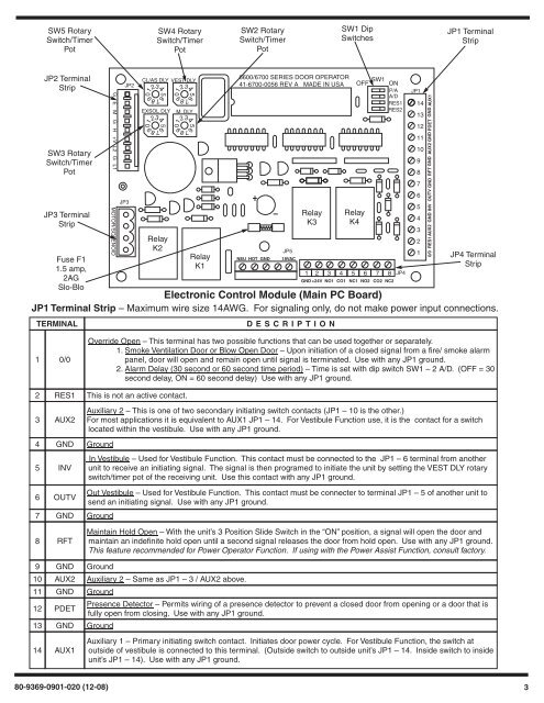
5678901234567890123456789012345678901234SW5 RotarySwitch/TimerPotSW4 RotarySwitch/TimerPotSW2 RotarySwitch/TimerPotSW1 DipSwitchesJP1 TerminalStripJP2 TerminalStripSW3 RotarySwitch/TimerPotJP3 TerminalStripFuse F11.5 amp,2AGSlo-BloG E M G H +V L2 G L1 MOTOR/SOLENOIDJP3JP2CL/AS DLY VEST DLYEXSOL DLYRelayK2M. DLYRelayK16600/6700 SERIES DOOR OPERATOR41-6700-0056 REV A MADE IN USASW1OFF ONP/AA/DRES1RES2NEU HOT GNDJP518VACRelayK3RelayK41 2 3 4 5 6 7 8GND +24V NO1 CO1 NC1 NO2 CO2 NC2JP4JP114131211109876543210/0 RES1 AUX2 GND INV OUTV GND RFT GND AUX2 GND PDET GND AUX1JP4 TerminalStripElectronic Control Module (Main PC Board)JP1 Terminal Strip – Maximum wire size 14AWG. For signaling only, do not make power input connections.TERMINALD E S CRIPTION1 0/0Override Open – This terminal has two possible functions that can be used together or separately.1. Smoke Ventilation Door or Blow Open Door – Upon initiation of a closed signal from a fire/ smoke alarmpanel, door will open and remain open until signal is terminated. Use with any JP1 ground.2. Alarm Delay (30 second or 60 second time period) – Time is set with dip switch SW1 – 2 A/D. (OFF = 30second delay, ON = 60 second delay) Use with any JP1 ground.2 RES1 This is not an active contact.3 AUX24 GND Ground5 INV6 OUTV7 GND GroundAuxiliary 2 – This is one of two secondary initiating switch contacts (JP1 – 10 is the other.)For most applications it is equivalent to AUX1 JP1 – 14. For Vestibule Function use, it is the contact for a switchlocated within the vestibule. Use with any JP1 ground.In Vestibule – Used for Vestibule Function. This contact must be connected to the JP1 – 6 terminal from anotherunit to receive an initiating signal. The signal is then programed to initiate the unit by setting the VEST DLY rotaryswitch/timer pot of the receiving unit. Use this contact with any JP1 ground.Out Vestibule – Used for Vestibule Function. This contact must be connecter to terminal JP1 – 5 of another unit tosend an initiating signal. Use with any JP1 ground.8 RFTMaintain Hold Open – With the unit’s 3 Position Slide Switch in the “ON” position, a signal will open the door andmaintain an indefinite hold open until a second signal releases the door from hold open. Use with any JP1 ground.This feature recommended for <strong>Power</strong> <strong>Operator</strong> Function. If using with the <strong>Power</strong> Assist Function, consult factory.9 GND Ground10 AUX2 Auxiliary 2 – Same as JP1 – 3 / AUX2 above.11 GND Ground12 PDET13 GND Ground14 AUX1Presence Detector – Permits wiring of a presence detector to prevent a closed door from opening or a door that isfully open from closing. Use with any JP1 ground.Auxiliary 1 – Primary initiating switch contact. Initiates door power cycle. For Vestibule Function, the switch atoutside of vestibule is connected to this terminal. (Outside switch to outside unit’s JP1 – 14. Inside switch to insideunit’s JP1 – 14). Use with any JP1 ground.80-9369-0901-020 (12-08) 3