6900 PowerMatic ® Low Energy Power Operator Wiring Instructions ...
6900 PowerMatic ® Low Energy Power Operator Wiring Instructions ...
6900 PowerMatic ® Low Energy Power Operator Wiring Instructions ...

Create successful ePaper yourself
Turn your PDF publications into a flip-book with our unique Google optimized e-Paper software.
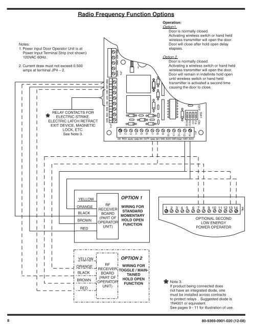
JP1Notes:1. <strong>Power</strong> input Door <strong>Operator</strong> Unit is at<strong>Power</strong> Input Terminal Strip (not shown)120VAC 60Hz.2. Current draw must not exceed 0.500amps at terminal JP4 – 2.RELAY CONTACTS FORELECTRIC STRIKE.ELECTRIC LATCH RETRACTEXIT DEVICE, MAGNETICLOCK, ETC.See Note 3.Radio Frequency Function OptionsGND +24V NO1 CO1 NC1 NO2 CO2 NC21 2 3 4 5 6 7 8JP4NEU HOT GND 18VAC0/0JP5123456RES1 AUX2 GND INV OUTV7GND89RFT GNDOperation:Option1.Door is normally closed.Activating wireless switch or hand heldwireless transmitter will open the door.Door will close after hold open delayelapses.Option 2.Door is normally closed.Activating a wireless switch or hand heldwireless transmitter will open the door.Door will remain in indefinite hold openuntil wireless switch or hand heldtransmitter is activated a second timecausing the door to close.10111213AUX2 GND PDET GND AUX1SW1OFF ONP/AA/DRES1RES214JP1YELLOWOPTION 1ORANGEBLACKBROWNREDRFRECEIVERBOARD(PART OFOPERATORUNIT)WIRING FORSTANDARDMOMENTARYHOLD OPENFUNCTION1 2 3 4 5 6 7 8 9 10 11 12 13 14OPTIONAL SECONDLOW ENERGYPOWER OPERATORYELLOWORANGEBLACKBROWNREDOPTION 2RF WIRING FORRECEIVER TOGGLE / MAIN-BOARD TAINED(PART OFHOLD OPENOPERATORFUNCTIONUNIT)Note 3:If product being connected doesnot have an integrated diode, onemust be installed across contractsto protect relays . Suggested diode is1N4001 or equivalent.See pages 9 - 11 for illustration of use.880-9369-0901-020 (12-08)