6900 PowerMatic ® Low Energy Power Operator Wiring Instructions ...
6900 PowerMatic ® Low Energy Power Operator Wiring Instructions ...
6900 PowerMatic ® Low Energy Power Operator Wiring Instructions ...

Create successful ePaper yourself
Turn your PDF publications into a flip-book with our unique Google optimized e-Paper software.
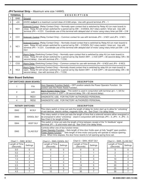
JP4 Terminal Strip – Maximum wire size 14AWG.TERMINALD E S CRIPTION1 GND Ground2 +24 24VDC output to a maximum current draw of 0.500 amps. Use with ground terminal JP4 – 13 NO1Solenoid Control (Relay Contact Only) – Normally open contact that is switched by Relay K3 (on main board) toclose. Relay K3 will remain switched for a period set by SW – 3 EXSOL DLY rotary switch / timer pot. Use withterminal JP4 – 4 CO1. Coordinate use of this terminal with delayed start of motor using rotary timer pot SW – 2 M4 CO1 Solenoid Control (Relay Contact Only) – Common contact for use with terminals JP4 – 3 NO1 and JP4 - 5 NC1.5 NC16 NO2Solenoid Control (Relay Contact Only) – Normally closed contact that is switched by Relay K3 (on main board) toopen. Relay K3 will remain switched for a period set by SW – 3 EXSOL DLY rotary switch / timer pot. Use withterminal JP4 – 4 CO1. Coordinate use of this terminal with delayed start of motor using rotary timer pot SW – 2 MDLY.Alarm Delay (Switching Contact Only) – Normally open contact that is switched by relay K4 (on main board) toclose. Relay K4 will remain switched for a period set by Dip Switch SW1 – 2 A/D (OFF = 30 second delay; ON = 60second delay). Use with terminal JP4 – 7 CO2.7 CO2 Alarm Delay (Switching Contact Only) – Common contact for use with terminals JP4 – 6 NO2 and JP4 – 8 NC2.8 NC2Alarm Delay (Switching Contact Only) – Normally closed contact that is switched by relay K4 (on main board) toopen. Relay K4 will remain switched for a period set by Dip Switch SW1 – 2 A/D (OFF = 30 second delay; ON = 60second delay). Use with terminal JP4 – 7 CO2.Main Board SwitchesDIP SWITCHES (MAIN BOARD)1 P/ADESCRIPTIONDoor <strong>Operator</strong> Function Switch – OFF position selects the <strong>Power</strong> <strong>Operator</strong> Function. Onposition sets the <strong>Power</strong> Assist Function.2 A/DAlarm System Delay Timer – This switch is used in conjunction with terminal Jp1– 1, 0/0 foroptional function 2. (OFF = 30 second delay, ON = 60 second delay).3 RES1 DIAGNOSTIC USE. FOR FACTORY AUTHORIZED PERSONAL.4 RES2 DIAGNOSTIC USE. FOR FACTORY AUTHORIZED PERSONAL.ROTARY SWITCHESSW2M DLYSW3 EXSOL DLYSW4 VEST DLYSW5 CL/AS DLYDESCRIPTIONThis rotary switch or timer pot sets the length of delay for motor start up to allow for “unlocking”of exit devices, electric strikes, magnetic locks, etc. See Chart 1 for delay times.This rotary switch or timer pot sets the length of time that a solenoid remains either energized orde-energized to allow “unlocking”. Used in conjunction with terminals JP4 – 3, JP4 – 4, JP5 – 5.See Chart 2 for length of time.This switch or timer pot sets the length of time between receipt of the “In Vestibule” signal(terminal JP1 – 5) and motor start-up. See Chart 3 for delay times.Controls either one of two function times:<strong>Power</strong> <strong>Operator</strong> Function – Sets length of time door holds open at fully “taught” open position.<strong>Power</strong> Assist Function – Sets length of time motor and pump will operate to reduce openingforce. When time elapses, the door force reverts to full opening spring force set.Chart 1 – SW2, M DLYLength of TimeSettings(Seconds)0.000.210.521.031.542.553.564.57Chart 2 – SW3, EXSOL DLYLength of TimeSettings(Seconds)001122436485106127Chart 3 – SW4, VEST DLYLength of Time(Seconds)01369142130Settings01234567Chart 4 – SW5, CL/AS DLYLength of TimeSettings(Seconds)002152103154205256307480-9369-0901-020 (12-08)