6900 PowerMatic ® Low Energy Power Operator Wiring Instructions ...
6900 PowerMatic ® Low Energy Power Operator Wiring Instructions ...
6900 PowerMatic ® Low Energy Power Operator Wiring Instructions ...

You also want an ePaper? Increase the reach of your titles
YUMPU automatically turns print PDFs into web optimized ePapers that Google loves.
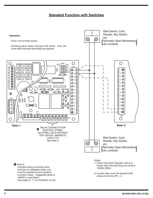
56789012345678901234567890123456789012340/0 RES1 AUX2 GND INV OUTV GND RFT GND AUX2 GND PDET GND AUX10/0 RES1 AUX2 GND INV OUTV GND RFT GND AUX2 GND PDET GND AUX1Standard Function with SwitchesOperation:Doors are normally closed.Activating either switch will open both doors. Door willclose after hold open time delay has elapsed.Wall Switch, CardReader, Key Switch,etc.Normally Open Momentarydry contactsG E M G H +V L2 G L1 MOTOR/SOLENOIDJP3JP2CL/AS DLY VEST DLYEXSOL DLY M. DLYNEU HOT GNDJP518VACSW1OFF ONP/AA/DRES1RES2JP1141312111098765432112345678910111213141 2 3 4 5 6 7 8GND +24V NO1 CO1 NC1 NO2 CO2 NC2JP4JP1Door 1 Door 2RELAY CONTACTS FORELECTRIC STRIKE.ELECTRIC LATCH RETRACTEXIT DEVICE, MAGNETICLOCK, ETC.Wall Switch, CardSee Note 3.Reader, Key Switch,etc.Normally Open Momentarydry contactsNote 3:If product being connected doesnot have an integrated diode, onemust be installed across contractsto protect relays . Suggested diode is1N4001 or equivalent.See pages 9 - 11 for illustration of use.Notes:1. <strong>Power</strong> input Door <strong>Operator</strong> Unit is at<strong>Power</strong> Input Terminal Strip (not shown)120VAC 60Hz.2. Current draw must not exceed 0.500amps at terminal JP4 – 2.680-9369-0901-020 (12-08)