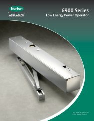
6900 PowerMatic ® Low Energy Power Operator Wiring Instructions ...
6900 PowerMatic ® Low Energy Power Operator Wiring Instructions ...
6900 PowerMatic ® Low Energy Power Operator Wiring Instructions ...

You also want an ePaper? Increase the reach of your titles
YUMPU automatically turns print PDFs into web optimized ePapers that Google loves.
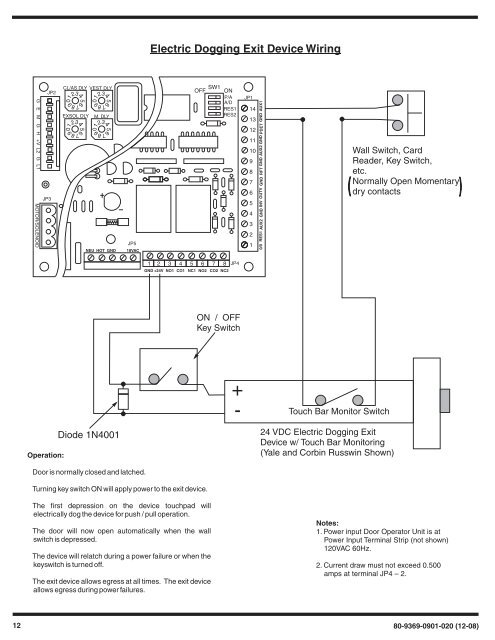
56789012345678901234567890123456789012340/0 RES1 AUX2 GND INV OUTV GND RFT GND AUX2 GND PDET GND AUX1Electric Dogging Exit Device <strong>Wiring</strong>G E M G H +V L2 G L1 MOTOR/SOLENOIDJP3JP2CL/AS DLY VEST DLYEXSOL DLY M. DLYNEU HOT GNDJP518VACSW1OFF ONP/AA/DRES1RES2JP11413121110987654321Wall Switch, CardReader, Key Switch,etc.Normally Open Momentarydry contacts1 2 3 4 5 6 7 8GND +24V NO1 CO1 NC1 NO2 CO2 NC2JP4ON / OFFKey SwitchOperation:Diode 1N4001Door is normally closed and latched.Turning key switch ON will apply power to the exit device.The first depression on the device touchpad willelectrically dog the device for push / pull operation.The door will now open automatically when the wallswitch is depressed.The device will relatch during a power failure or when thekeyswitch is turned off.The exit device allows egress at all times. The exit deviceallows egress during power failures.+-Touch Bar Monitor Switch24 VDC Electric Dogging ExitDevice w/ Touch Bar Monitoring(Yale and Corbin Russwin Shown)Notes:1. <strong>Power</strong> input Door <strong>Operator</strong> Unit is at<strong>Power</strong> Input Terminal Strip (not shown)120VAC 60Hz.2. Current draw must not exceed 0.500amps at terminal JP4 – 2.1280-9369-0901-020 (12-08)