6900 PowerMatic ® Low Energy Power Operator Wiring Instructions ...
6900 PowerMatic ® Low Energy Power Operator Wiring Instructions ...
6900 PowerMatic ® Low Energy Power Operator Wiring Instructions ...

Create successful ePaper yourself
Turn your PDF publications into a flip-book with our unique Google optimized e-Paper software.
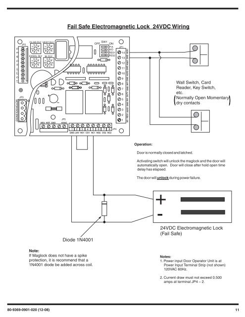
56789012345678901234567890123456789012340/0 RES1 AUX2 GND INV OUTV GND RFT GND AUX2 GND PDET GND AUX1+-Fail Safe Electromagnetic Lock 24VDC <strong>Wiring</strong>G E M G H +V L2 G L1 MOTOR/SOLENOIDJP3JP2CL/AS DLY VEST DLYEXSOL DLY M. DLYNEU HOT GNDJP518VACSW1OFF ONP/AA/DRES1RES2JP11413121110987654321Wall Switch, CardReader, Key Switch,etc.Normally Open Momentarydry contacts1 2 3 4 5 6 7 8GND +24V NO1 CO1 NC1 NO2 CO2 NC2JP4Operation:Door is normally closed and latched.Activating switch will unlock the maglock and the door willautomatically open. Door will close after hold open timedelay has elapsed.The door will unlock during power failure.Diode 1N4001Note:If Maglock does not have a spikeprotection, it is recommend that a1N4001 diode be added across coil.24VDC Electromagnetic Lock(Fail Safe)Notes:1. <strong>Power</strong> input Door <strong>Operator</strong> Unit is at<strong>Power</strong> Input Terminal Strip (not shown)120VAC 60Hz.2. Current draw must not exceed 0.500amps at terminal JP4 – 2.80-9369-0901-020 (12-08) 11