6900 PowerMatic ® Low Energy Power Operator Wiring Instructions ...
6900 PowerMatic ® Low Energy Power Operator Wiring Instructions ...
6900 PowerMatic ® Low Energy Power Operator Wiring Instructions ...

You also want an ePaper? Increase the reach of your titles
YUMPU automatically turns print PDFs into web optimized ePapers that Google loves.
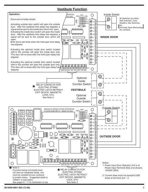
56789012345678901234567890123456789012345678901234567890123456789012345678901234Operation:JP3JP5NEU HOT GND 18VACwith-in the corridor will open the outside door only.Vestibule Function6600/6700 SERIES DOOR OPERATORCL/AS DLY VEST DLYSW1JP241-6700-0056 REV A MADE IN USA OFF ONP/ADoors are normally closed.A/DRES1EXSOL DLY M. DLYRES2Activating outside door switch will open the outsideG E M G H +V L2 G L1 MOTOR/SOLENOIDdoor. After the vestibule time delay has elapsed, asignal will be sent to the inside door which will open.Activating the inside door switch will open the insidedoor. After the vestibule time delay has elapsed, asignal will be sent to the outside door which willopen.Both doors will close when the hold open time delayhas elapsed.Activating the optional inside door switch locatedwith-in the corridor will open the inside door only.This door will re-close after the hold open delay haselapsed.Activating the optional outside door switch locatedThis door will re-close after the hold open delay haselapsed.1 2 3 4 5 6 7 8GND +24V NO1 CO1 NC1 NO2 CO2 NC2JP4JP114131211109876543210/0 RES1 AUX2 GND INV OUTV GND RFT GND AUX2 GND PDET GND AUX1Inside SwitchINSIDE DOORAll Switches are eitherWall Switches, CardReaders, Key Switches,etc.Normally Open Momentarydry contactsRELAY CONTACTS FORELECTRIC STRIKE.ELECTRIC LATCH RETRACTEXIT DEVICE, MAGNETICLOCK, ETC.See Note 3.OptionalInsideCorridor SwitchVESTIBULEOptionalOutsideCorridor SwitchG E M G H +V L2 G L1 MOTOR/SOLENOIDJP3JP2CL/AS DLY VEST DLYEXSOL DLYM. DLY6600/6700 SERIES DOOR OPERATOR41-6700-0056 REV A MADE IN USASW1OFF ONP/AA/DRES1RES2NEU HOT GNDJP518VACJP114131211109876543210/0 RES1 AUX2 GND INV OUTV GND RFT GND AUX2 GND PDET GND AUX1Outside SwitchOUTSIDE DOORNote 3:If product being connected doesnot have an integrated diode, onemust be installed across contractsto protect relays . Suggested diode is1N4001 or equivalent.See pages 9 - 11 for illustration of use.1 2 3 4 5 6 7 8GND +24V NO1 CO1 NC1 NO2 CO2 NC2RELAY CONTACTS FORELECTRIC STRIKE.ELECTRIC LATCH RETRACTEXIT DEVICE, MAGNETICLOCK, ETC.See Note 3.JP4Notes:1. <strong>Power</strong> input Door <strong>Operator</strong> Unit is at<strong>Power</strong> Input Terminal Strip (not shown)120VAC 60Hz.2. Current draw must not exceed 0.500amps at terminal Jp4 – 2.80-9369-0901-020 (12-08) 7