Installation Manual - James Hardie
Installation Manual - James Hardie
Installation Manual - James Hardie

Create successful ePaper yourself
Turn your PDF publications into a flip-book with our unique Google optimized e-Paper software.
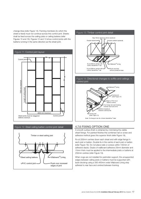
change lines (refer Figure 14). Framing members (to which thesheet is fixed) must not continue across this control joint. Sheetsshall be fixed across the ceiling joists or ceiling battens (referFigures 15 and 16). Figures 12 and 13 show control joints with thebattens running in the same direction as the sheet joint.Figure 13: Timber control joint detailFigure 11: Control joint layoutFix at 200mm centres with2.8mm <strong>Hardie</strong>Flex nailFigure 14: Directional changes to soffits and ceilings —control jointFigure 12: Steel ceiling batten control joint detail4.7.6 Fixing OPTION OneA smooth surface finish is obtained by minimising the visiblesheet fixings. For painted finishes the combined nail or screw andadhesive method gives this superior finish (refer Figure 19).Fix at 200mm centres down each sheet end with edge fixings ineach joist or batten. Double-fix in the centre of each joist or batten(refer Figure 19). Do not place nails or screws within 100mm ofadhesive daubs. Daubs of wallboard adhesive 25mm diameter and15mm thick must be applied to the intermediate joists or battens at250mm centres (refer Figure 19).When nogs are not installed for perimeter support, the unsupportededges between ceiling joists or battens must be supported withback blocking using a 300-400mm wide Villaboard Lining stripadhered to rear face and centred between framing.<strong>James</strong> <strong>Hardie</strong> Eaves And Soffits <strong>Installation</strong> <strong>Manual</strong> February 2013 New Zealand 17