DIODE / THYRISTOR MODULE - Datasheets.pl
DIODE / THYRISTOR MODULE - Datasheets.pl
DIODE / THYRISTOR MODULE - Datasheets.pl

Create successful ePaper yourself
Turn your PDF publications into a flip-book with our unique Google optimized e-Paper software.
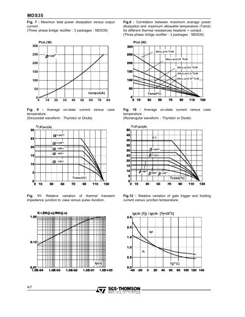
MDS35Fig. 7 : Maximun total power dissipation versus outputcurrent .(Three phase bridge rectifier : 3 packages : MDS35)Ptot.(W)300Fig.8 : Correlation between maximum average powerdissipation and maximum allowable temperature (Tamb)for different thermal resistances heatsink + contact .(Three phase bridge rectifier : 3 packages : MDS35)Ptot.(W)250200150100o=120Rth(c.a)=0 OC/WORth(c-a)=O.25 C/WRth(c-a)=0.5 OC/WORth(c-a)=1.0 C/WORth(c-a)=0.75 C/W50Ioutput(A)00 10 20 30 40 50 60 70 80Fig. 9 : Average on-state current versus casetemperature .(Sinusoidal waveform : Thyristor or Diode)I T,IF(av)(A)Fig. 10 : Average on-state current versus casetemperature .(Rectangular waveform : Thyristor or Diode)IT,IF(av)(A)Tamb( oC)=180 o=120 oD.C.=90 o=60 o=180o=120o=30 oTcase(oC)o=90=60oo=30oTcase( c)Fig. 11: Relative variation of thermal transientimpedance junction to case versus pulse duration.Fig.12 : Relative variation of gate trigger and holdingcurrent versus junction temperature.Igt;Ih [Tj] / Igt;Ih [Tj=25 C]oIgtIhtp(s)oTj( C)4/7