JHD1130 Owners Manual - ASA Electronics
JHD1130 Owners Manual - ASA Electronics
JHD1130 Owners Manual - ASA Electronics

Create successful ePaper yourself
Turn your PDF publications into a flip-book with our unique Google optimized e-Paper software.
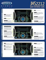
<strong>JHD1130</strong>AM/FM/WB/AUX-IN Heavy Duty RadioInstallation and Operation <strong>Manual</strong>Guide d’installation et d’opérationAS/PSDNUPT FPTYMENUINFOENTER<strong>JHD1130</strong>40Wx44
<strong>JHD1130</strong>CONTENTSIntroduction......................................................................................................... 1Safety Information .............................................................................................. 2Installation........................................................................................................... 3Wiring................................................................................................................... 4Basic Operation .................................................................................................. 5Tuner Operation.................................................................................................. 7Care and Maintenance........................................................................................ 9Troubleshooting.................................................................................................. 9Specifications ................................................................................................... 10ii
<strong>JHD1130</strong>INTRODUCTIONSystem FeaturesFeatures of the Jensen <strong>JHD1130</strong> mobile audio system include:• 10 Character Alpha-Numeric Segmented LCD• AM/FM US/EURO Tuner with 30 Presets (12 AM, 18 FM)• RBDS (Radio Broadcast Data Service) with PTY Search• Weatherband Tuner• Mute• Pre-set Equalizer - 5 settings (Flat, Rock, Pop, Classical, User)• Electronic Bass, Treble, Balance and Fader Controls• Output Power 40W x 4• Clock 12/24 Hour Selectable• IR Wireless Remote Control Ready (sold separately)• 2-Wire Power with Non-Volatile Memory and Clock/Time Support• Auxiliary Audio Input (Front 3.5mm Stereo Jack)Content List• Jensen Heavy Duty Radio• Hardware Kit• 15AMP Fuse• Installation <strong>Manual</strong>• Quick Reference GuideHARDWARE KIT CONTENTSFLANGE NUTSMOUNTING STRAPDIN SLEEVEREMOVAL TOOLMOUNTING SCREWMOUNTING BUSHING1
<strong>JHD1130</strong>SAFETY INFORMATIONWhen DrivingKeep the volume level Iow enough to be aware of the road and traffic conditions.When Washing Your VehicleDo not expose the product to water or excessive moisture. Moisture can cause electricalshorts, fire or other damage.When ParkedParking in direct sunlight can produce very high temperatures inside your vehicle. Give theinterior a chance to cool down before starting playback.Use the Proper Power SupplyThis product is designed to operate with a 12 volt DC negative ground battery system.WARNING:• TO REDUCE THE RISK OF FIRE OR ELECTRIC SHOCK, DO NOT EXPOSE THISEQUIPMENT TO RAIN OR MOISTURE.• TO REDUCE THE RISK OF FIRE OR ELECTRIC SHOCK AND ANNOYINGINTERFERENCE, USE ONLY THE RECOMMENDED ACCESSORIES.2
<strong>JHD1130</strong>INSTALLATIONThis unit is designed for installation in vehicle cabs with an existing 1-DIN radio opening. Inmany cases, a special installation kit will be required to mount the radio to the dashboard. Seethe dealer where the radio was purchased for kit availability. Always check the kit applicationbefore purchasing to make sure the kit works with your vehicle.Before You Begin1. Disconnect BatteryBefore you begin, always disconnect the battery negative terminal.2. Remove Transport ScrewsImportant Notes• Before final installation, test the wiring connections to make sure the unit is connectedproperly and the system works.• Use only the parts included with the unit to ensure proper installation. The use ofunauthorized parts can cause malfunctions.• Consult with your nearest dealer if installation requires the drilling of holes or othermodifications to your vehicle.• Install the unit where it does not interfere with driving and cannot injure passengers duringa sudden or emergency stop.• If the installation angle exceeds 30º from horizontal, the unit might not give optimumperformance.• Avoid installing the unit where it will be subject to high temperatures from direct sunlight,hot air, or from a heater, or where subject to excessive dust, dirt or vibration.DIN Front Mount1. Slide the mounting sleeve off of the chassisif it has not already been removed. IfDashboardlocked into position, use the removal keysBend Tabs182(supplied) to disengage it. The removalkeys are depicted in “Removing the Unit”53on page 3.2. Check the dashboard opening size byScrew Studsliding the mounting sleeve into it. If theopening is not large enough, carefully cutor file as necessary until the sleeve easilyslides into the opening. Do not force thesleeve into the opening or cause it to bendor bow. Check that there will be sufficientspace behind the dashboard for the radio chassis.3. Locate the series of bend tabs along the top, bottom and sides of the mounting sleeve.With the sleeve fully inserted into the dashboard opening, bend as many of the tabsoutward as necessary to firmly secure the sleeve to the dashboard.4. Place the radio in front of the dashboard opening so the wiring can be brought through themounting sleeve.5. Follow the wiring diagram carefully and make certain all connections are secure andinsulated with crimp connectors or electrical tape to ensure proper operation.6. After completing the wiring connections, turn the unit on to confirm operation (vehicleaccessory switch must be on). If the unit does not operate, recheck all wiring until theproblem is corrected. Once proper operation is achieved, turn the accessory switch offand proceed with final mounting of the chassis.7. Carefully slide the radio into the mounting sleeve making sure it is right-side-up until it isfully seated and the spring clips lock it into place.8. Attach one end of theperforated support strap(supplied) to the screwDashboardstud on the rear of theSupport Strapchassis using the hex nutprovided. Fasten thePlain Washerother end of theScrew (5 x 25mm)perforated strap to aRubber Bushingsecure part of theScrew Studdashboard either aboveHex Nut (5mm)or below the radio usingthe screw and plainwasher provided. Bendthe strap, as necessary,to position it. Somevehicle installationsprovide cavity for rearsupport. In these applications, place the rubber bushing over the screw stud and insertthe radio.CAUTION: The perforated rear support strap or rear rubber mounting bushing mustbe used in the installation of the radio. Installation without either may result indamage to the radio or the mounting surface and void the manufacturer’s warranty.9. Test radio operation by referring to the operating instructions for the unit.Removing the UnitTo remove the radio afterSleeveinstallation, remove the plastic endcaps, insert the removal keys Removal Keystraight back until they click, andthen pull the radio out. If removalkeys are inserted at an angle, theywill not lock properly to release theunit.Reconnect BatteryWhen wiring is complete, reconnectthe battery negative terminal.Removal Key3
<strong>JHD1130</strong>WIRING4
<strong>JHD1130</strong>System Menu1. Press and hold the PTY/MENU button (2) for more than 2 seconds to enter the systemmenu. The first menu item, “KEYBEEP”, will appear on the display.2. Press the TUNE/SEEK |>| (18, 19) button repeatedly to navigate the system menu.3. Press the INFO/ENTER button (16) to select the desired item.4. Press the INFO/ENTER button again to adjust the selected menu item.The following items can be adjusted:• KEYBEEP (Clk (click) / Bep (beep) / Off): Turn the audible beep On/Off (heard whenfunctions/buttons are selected).• LCDLITE (1-10): Adjust LCD brightness.• TUNING (USA / EURO): Set frequency spacing for various regions.• P-- CLOCK (1-10 / Off)• CLK FMT (12Hour / 24Hour): Select 12 or 24 hour display mode.• CLK (HH : MM): Set clock.• Press the INFO/ENTER button (16) to view the clock set screen.• Press the INFO/ENTER button to move to the next digit.• Press the TUNE/SEEK |>| (18, 19) buttons to adjust the selected digit.• PREONLY (On / Off): Turn preset-only tuning on/off.• BAT ALRM (Off / On): When ON, radio will alert when vehicle battery voltage is below10.8 VDC.• BAT OFF (Off / On): When ON, radio will automatically turn off when vehicle batteryvoltage is below 10.8 VDC.• RESET ALL : Press the INFO/ENTER button (16) to return the EEPROM tofactory default set up values.EqualizerPress the EQ/LOUD button (11) to choose one of the following pre-defined bass and treblecurves: USER > FLAT > ROCK > CLAS(SICAL) > POP.LoudnessPress and hold the EQ/LOUD button (11) to toggle loudness on/off. When listening to music atlow volumes, this feature will boost the bass and treble ranges to compensate for thecharacteristics of human hearing.Auxiliary InputTo access an auxiliary device:1. Connect the portable audio player to the AUX IN on the front panel (17).2. Press the MODE button (4) to select “Auxiliary” mode.3. Press MODE again to cancel “Auxiliary” mode and go to the next mode.Liquid Crystal Display (LCD)The current frequency and activated functions are shown on the LCD panel (21).Setting the ClockTo set the clock to display the current time, turn the vehicle ignition on and turn the radio on.Enter the system menu and adjust the clock by selecting the “CLK” menu item.• Press the INFO/ENTER button (16) to view the clock set screen.• Press the TUNE/SEEK |>| (18, 19) buttons to adjust the selected digit.• Press the INFO/ENTER button to move to the next digit.• Press the TUNE/SEEK |>| (18, 19) buttons to adjust the selected digit.When no adjustment is made for 15 seconds, the time will become set and normal operationwill resume.Display ModesPress the T/F button (12) to switch between LCD clock display and source display.NOTE: LCD panels may take longer to respond when subjected to cold temperatures foran extended period of time. In addition, the visibility of the characters on the LCD maydecrease slightly. The LCD display will return to normal when the temperature increasesto a normal range.6
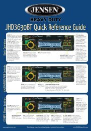
<strong>JHD1130</strong>TUNER OPERATION311220TF14AS/PS<strong>JHD1130</strong>21 18 1940Wx444 15 11 17 8 6 5 7 9 10 2 13DNPTYMENUUPINFOENTER16Automatically Store / Preset Scan (AS/PS)Automatically StoreSelect an AM or FM band. Press and hold the AS/PS button (14) for more than 2 seconds toautomatically select 18 strong stations (12 for AM). “FM STORE” or “AM STORE” appears onthe screen and the new stations replace any stations already stored.Preset ScanSelect a band. Press AS/PS (14) to scan all stored stations. The unit will pause for 8 secondsat each preset station. Press AS/PS again to stop scanning when the desired station isreached.RBDS OperationThis unit is equipped to display RBDS (Radio Broadcast Data Service) information whenbroadcast by the radio station.Select a BandPress the BAND/WB button (15) to change between three FM bands and two AM bands.Press and hold the BAND/WB button to access the Weatherband (WB).<strong>Manual</strong> TuningPress the TUNE/SEEK >>| or |>| or |>| or |
<strong>JHD1130</strong>Weather Band OperationWhat is the NOAA Weather Radio/Weatheradio Canada?NOAA (National Oceanic and Atmospheric Administration) is a nationwide system thatbroadcasts local weather emergency information 24 hours a day via the National WeatherService (NWS) network. The U.S. network has more than 530 stations covering the 50 statesas well as the adjacent costal waters, Puerto Rico, the U.S. Virgin Islands and the U.S. PacificTerritories. Each local area has its own transmitting station and there are a total of sevenbroadcasting frequencies used. A similar system is available in Canada under the WeatheradioCanada service administered by Environment Canada.Tuning to WeatherbandPress and hold the BAND/WB button (15) to access the Weatherband. The indication "WB"will appear on the display panel, along with the current number and channel indication: "WB-1",“WB-2", "WB-3", "WB-4", "WB-5", "WB-6" or "WB-7". The seven frequencies are shown in thefollowing table:Table 1: WB FrequenciesFrequency (MHz)Preset162.400 2162.425 4162.450 5162.475 3162.500 6162.525 -162.550 1The above table also shows which preset button will access the frequency. Note that onefrequency cannot be accessed using a preset button. The frequency can only be reachedusing the tuning controls.Use the TUNE/SEEK >>| or |
<strong>JHD1130</strong>CARE AND MAINTENANCE• Keep the product dry. If it does get wet, wipe it dry immediately. Liquids might containminerals that can corrode the electronic circuits.• Keep the product away from dust and dirt, which can cause premature wear of parts.• Handle the product gently and carefully. Dropping it can damage circuit boards andcases, and can cause the product to work improperly.• Wipe the product with a dampened cloth occasionally to keep it looking new. Do not useharsh chemicals, cleaning solvents, or strong detergents to clean the product.• Use and store the product only in normal temperature environments. High temperaturecan shorten the life of electronic devices, damage batteries, and distort or melt plasticparts.IgnitionThe most common source of noise in reception is the ignition system. This is a result of theradio being placed close to the ignition system (engine). This type of noise can be easilydetected because it will vary in intensity of pitch with the speed of the engine.Usually, the ignition noise can be suppressed considerably by using a radio suppression typehigh voltage ignition wire and suppressor resistor in the ignition system. (Most vehicles employthis wire and resistor but it may be necessary to check them for correct operation.) Anothermethod of suppression is the use of additional noise suppressors. These can be obtained frommost professional mobile electronics retailers.InterferenceRadio reception in a moving environment is very different from reception in a stationaryenvironment (home). It is very important to understand the difference.AM reception will deteriorate when passing under a bridge or when passing under high voltagelines. Although AM is subject to environmental noise, it has the ability to received at greatdistance. This is because broadcasting signals follow the curvature of the earth and arereflected back by the upper atmosphere.TROUBLESHOOTINGNo powerNo soundSymptom Cause SolutionThe operation keys donot workCannot tune to radio station,auto-seek does notworkThe vehicle’s accessoryswitch is not onThe fuse is blownVolume is too low or systemis mutedWiring is not properly connectedThe built-in microcomputeris not operating properlydue to noiseThe antenna cable is notconnectedThe signals are too weakIf the power supply is properlyconnected to the vehicle’s accessoryterminal, switch the ignitionkey to “ACC” or “Run”Replace the fuseAdjust volume to audible levelCheck wiring connectionsPress the RESET buttonCheck antenna cableSelect a station manually9
<strong>JHD1130</strong>SPECIFICATIONSFM RadioFrequency Coverage (USA) . . . . . . . . . . . . . . . . . . . . . . . . . . . . . . . . . . . 87.5 to 107.9 MHzFrequency Coverage (Europe) . . . . . . . . . . . . . . . . . . . . . . . . . . . . . . . . . . . 87.5 to 108 MHzSensitivity (S/N=30dB) . . . . . . . . . . . . . . . . . . . . . . . . . . . . . . . . . . . . . . . . . . . . . . . . . 2.2µVImage Rejection . . . . . . . . . . . . . . . . . . . . . . . . . . . . . . . . . . . . . . . . . . . . . . . . . . . . . >45 dBStereo Separation . . . . . . . . . . . . . . . . . . . . . . . . . . . . . . . . . . . . . . . . . . . . . . . . . . . . >25 dBAM/MWFrequency Range (USA). . . . . . . . . . . . . . . . . . . . . . . . . . . . . . . . . . . . . . . . . 530-1710 kHzFrequency Range (Europe). . . . . . . . . . . . . . . . . . . . . . . . . . . . . . . . . . . . . . . 522-1620 kHzSensitivity (S/N=20dB) . . . . . . . . . . . . . . . . . . . . . . . . . . . . . . . . . . . . . . . . . . . . . . . . . 21 µVGeneralOperating Voltage . . . . . . . . . . . . . . . . . . . . . . . . . . . . . . . . . . . . . . . . . . . . . . . . .DC 12 VoltsGrounding System . . . . . . . . . . . . . . . . . . . . . . . . . . . . . . . . . . . . . . . . . . . Negative GroundSpeaker Impedance . . . . . . . . . . . . . . . . . . . . . . . . . . . . . . . . . . . . . . .4-8 ohms per channelTone Controls:Bass (at 100 Hz) . . . . . . . . . . . . . . . . . . . . . . . . . . . . . . . . . . . . . . . . . . . . . . . . . : ±10 dBTreble (at 10 kHz). . . . . . . . . . . . . . . . . . . . . . . . . . . . . . . . . . . . . . . . . . . . . . . . . : ±10 dBPower Output . . . . . . . . . . . . . . . . . . . . . . . . . . . . . . . . . . . . . . . . . . . . . . . . . . . . . . 40W x 4Idle/Standby Current . . . . . . . . . . . . . . . . . . . . . . . . . . . . . . . . . . . . . . . . . . . . . . . . . . . 40mACurrent Drain. . . . . . . . . . . . . . . . . . . . . . . . . . . . . . . . . . . . . . . . . . . . . . . . . . . . . . . . . . 9.5ADimensions . . . . . . . . . . . . . . . . . . . . . . . . . . . . . . . . . . . . . . . . .7.4” (W) x 9.9” (D) x 2.3” (H)10
<strong>JHD1130</strong>11
<strong>ASA</strong> <strong>Electronics</strong> Corporationwww.asaelectronics.comwww.jensenheavyduty.com©2012 <strong>ASA</strong> <strong>Electronics</strong> Corporationv.083112