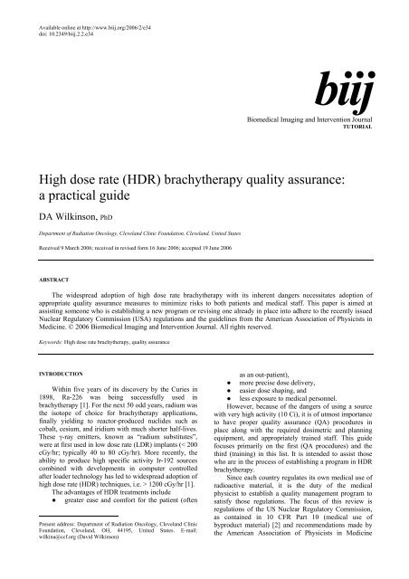
(HDR) brachytherapy quality assurance - Biomedical Imaging and ...
(HDR) brachytherapy quality assurance - Biomedical Imaging and ...
(HDR) brachytherapy quality assurance - Biomedical Imaging and ...

You also want an ePaper? Increase the reach of your titles
YUMPU automatically turns print PDFs into web optimized ePapers that Google loves.
DA Wilkinson. Biomed <strong>Imaging</strong> Interv J 2006; 2(2):e34 2This page number is notfor citation purposeThe Clevel<strong>and</strong> Clinic FoundationMANCHESTER TEMPLATEThe Clevel<strong>and</strong> Clinic FoundationThe Clevel<strong>and</strong> Clinic Foundation<strong>HDR</strong> Fletcher-suitGYN TEMPLATEFigure 1 Examples of <strong>HDR</strong> applicators used for lung, rectal, <strong>and</strong> gynecologic diseases.(AAPM). The latter are intended to provide the medicalphysicist in the USA (<strong>and</strong> it is hoped other nations aswell) the proper guidance to ensure that <strong>brachytherapy</strong>procedures are carried out safely <strong>and</strong> with due attentionto these rules. There are two AAPM task group (TG)reports that are particularly relevant to <strong>HDR</strong> QA. Theyare TG 56: Code of practice for <strong>brachytherapy</strong> physics[3], <strong>and</strong> especially TG 59: <strong>HDR</strong> <strong>brachytherapy</strong> treatmentdelivery [4]. Another useful reference for <strong>brachytherapy</strong><strong>quality</strong> <strong>assurance</strong> has been published by ESTRO <strong>and</strong> isavailable on their website [5]. This paper will providedetails about <strong>HDR</strong> QA as it is performed in our radiationtherapy department (on a Nucletron Microselectronsystem) <strong>and</strong> how the QA program is related to the NRCregulations <strong>and</strong> the task group recommendations.APPLICATOR QAPrior to the initial use of a new (or replacement)applicator, it is necessary to verify that the source dwellpositions correspond to the radiographic markerpositions used in simulation <strong>and</strong> treatment planning. TG-56 recommends that coincidence of dummy <strong>and</strong>radioactive sources be checked annually as well. Thereare many st<strong>and</strong>ard applicators; photographs of several ofthose used in our institution are shown in Figure 1.The method we employ to verify coincidence ofdwell position <strong>and</strong> radiographic marker isautoradiography. An applicator is taped securely to asealed film envelope (Figure 2) <strong>and</strong> the <strong>HDR</strong> after loaderis programmed to send the source to a few appropriatelychosen dwell positions for less than 1 second (e.g. 0.3 sfor 0.31 GBq source). Next, the film plus applicator istransferred to a diagnostic X-ray source such as asimulator, the dummy source markers are placed in theapplicator <strong>and</strong> the film exposed <strong>and</strong> developed (e.g. 125kVp, 125 mAs for Kodak XV film). An example of thisis shown in Figure 3. TG-56 recommends that the
DA Wilkinson. Biomed <strong>Imaging</strong> Interv J 2006; 2(2):e34 3This page number is notfor citation purpose1713915Figure 2 Photograph of a ring applicator secured to a base platewith film taped securely in place.Figure 3 Autoradiograph of a 3 cm ring showing 5 dwellpositions (1,5,9,13,17) as well as the interveningdummy markers (unnumbered arrows). Dwell positionsare for the 0.5 cm step-size.coincidence of dummy <strong>and</strong> active sources be within 2mm; the NRC regulations call for ± 1 mm.PERIODIC SPOT-CHECKThe new NRC regulations require a periodic spotcheckof each <strong>HDR</strong> unit prior to the first use on anygiven day that the after loader is in operation <strong>and</strong> aftereach new source installation. These spot-checks need notbe done by the authorized medical physicist, but thelatter must review the results <strong>and</strong> notify the licensee inwriting of his findings. Table 1 lists the checks that mustbe performed at a minimum to assure proper operation ofthe unit according to NRC Regulations 10 CFR Part 35.A convenient way of implementing <strong>and</strong> recordingthe above <strong>quality</strong> <strong>assurance</strong> is by using a checklist suchas the one our clinic uses as shown in figure 4.Certain tests require only a simple inspection toensure that materials are present, viz. User manual,Removal kit, Emergency instructions, Bailout pig,Radiation alarm setting, <strong>and</strong> Printer paper. Switching onthe system allows the tests in item 7 to be performed.The source activity comparison can be made using atable generated by the medical physicist (Figure 5). Thiswill also satisfy the requirement (see Full Calibrationbelow) for performing decay correction which must bedone by the authorized medical physicist. Agreementshould easily be within 1 percent tolerances.For the remaining tests, the active source will needto be deployed. For this, the system can be programmedmanually each time or a st<strong>and</strong>ard program recalled fromthe system memory. A single dwell time of 20 to 30 ssuffices to test the door interlock, the interrupt button,<strong>and</strong> the emergency off button as well as to verify that theappropriate exposure indicators <strong>and</strong> radiation monitorsare functioning properly. The spot check form requirestesting of the functioning of the meter in the treatmentroom (Figure 6) under battery power alone. Its alarmsetting of 4 mR/hr was established so as to be aboveexposure levels in the room due to an adjacent linactherapy suite. As an additional safety measure, we have acalibrated GM meter that is carried by h<strong>and</strong> by personnelupon entering the treatment room. It is checked using a 1mCi Cs-137 source that yields a 10 mR/hr contact value.The remaining item is an estimate of timer accuracy. Forthis, a stopwatch is used to time a 30 s dwell. Typicalerror estimates are well below 1 second.FULL CALIBRATIONA “full calibration” is m<strong>and</strong>ated for several differentcircumstances, e.g. before first medical use, following asource change or any major repair, etc. Since the sourcein most, if not all, modern <strong>HDR</strong> after loaders is Ir-192with a half-life of approximately 74 days, therequirement for quarterly calibration [2] does notformally apply. However, it is usual to replace an iridiumsource four times a year so as to maintain reasonabledose rates <strong>and</strong> treatment times. Quarterly QA testing of<strong>HDR</strong> after loaders was recommended in the report of TG56. The components of a full calibration as defined inNRC Regulations 10 CFR Part 35 are listed in Table 2.
DA Wilkinson. Biomed <strong>Imaging</strong> Interv J 2006; 2(2):e34 4This page number is notfor citation purposeFigure 5 Source decay on physicist-generated spreadsheet (left)<strong>and</strong> printout from the <strong>HDR</strong> control console (right). Theactual numbers for the particular treatment date are36772 <strong>and</strong> 36754 mGy m2 h-1 (respectively).Figure 4 Spot-check form used each day of patient treatment.The form we employ for the full calibration is on anExcel spreadsheet (Figure 7) which allows convenientcalculations of source activity <strong>and</strong> positioning as well astimer accuracy <strong>and</strong> linearity. The activity of the source ismeasured using a well chamber <strong>and</strong> electrometer havingcalibrations traceable to the National Institute ofSt<strong>and</strong>ards <strong>and</strong> Technology (within 2 years as indicatedby the dates on the form). The electrometer needs to becalibrated in both current <strong>and</strong> charge (integral) modes.The source is programmed to go to a series of positionswithin the well chamber <strong>and</strong> the maximum currentreading is used to calculate the activity in air kerma units.This value is then compared to the manufacturer’s statedactivity decayed to the day of measurement. Agreementis typically within 2%. The regulations allow a 5% range.If equipment calibrations traceable to a national st<strong>and</strong>ardare not available, dosimetry system constancy checks canbe performed using a long-lived source such as Cs-137[5]. This is not a desirable substitute for propercalibration.Positioning accuracy is measured using a specialruler supplied by the manufacturer (Figure 8). Theprogrammed position (e.g. 995) is for the center of thesource, hence the correction (one-half of the sourcelength, or 2.15 mm) for the leading edge. The one mmcriterion may not be satisfied if there is much curvaturein the measuring system (see Figure 9). Thus, some caremust be taken to ensure that the transfer tube isreasonably straight <strong>and</strong> horizontal.We perform the battery back-up test by shutting offthe AC power to the after loader while a source has beendeployed. This makes it a somewhat different testcompared to the one in the spot-check where theemergency off button is pushed. That the source has beenretracted is printed out at the control console <strong>and</strong> isverified by the radiation monitor indicating exposurerates below the set value (4 mR/hr).Timer error <strong>and</strong> linearity are measured using atechnique established for teletherapy sources. Charge iscollected <strong>and</strong> measured in the well chamber for a set ofpredetermined times. The pass/fail criteria we adoptedseem both reasonable <strong>and</strong> reproducible <strong>and</strong> well withinthe capability of the system.We test the integrity of the transfer tube/applicatorsystem in three ways.● Once a program has been loaded into thecontrol unit, a transfer tube + applicator isattached to Channel 1 but the indexer ring is notlocked.● The second test has the transfer tube removedfrom Channel 1 <strong>and</strong> the ring locked.● The final test has the transfer tube inserted intoChannel 1, the ring locked, <strong>and</strong> an applicatorwith an obstruction in it attached. It should beadded that in the Nucletron system, failure toconnect the transfer tube to the applicatorproperly will usually generate the same errorcode as an obstruction.
DA Wilkinson. Biomed <strong>Imaging</strong> Interv J 2006; 2(2):e34 5This page number is notfor citation purpose<strong>HDR</strong> FULL CALIBRATIONNucletron MicroSelecton <strong>HDR</strong> S/N 9213Date: December 5,2005 Time: 10:201. SOURCE ACTIVITYChamber: St<strong>and</strong>ard <strong>Imaging</strong> <strong>HDR</strong> 1000 Plus; S/N A943623Electrometer: CNMC K602; S/N 51090Source # Stated activity Reference date Check date Decayed actD35A-2870 41250 11/17/2005 12/5/2005 34852.6471T = 23.2 C t,p: 1.0188P = 749 Calibration factor: 4921 Calibrated: Apr 05Electrometer factor: 0.981 Calibrated: Oct 04Electr. rdgsPosition Rdg (Amp E-08)940 7.066945 7.102950 7.117955 7.109960 7.077Measured activity (U) 35003.72 8.68 CiRatio: measured/stated activity 1.0043_____ within ± 5%2. SOURCE POSITIONING ACCURACY (Mode 13)Figure 6 Exposure rate meter mounted on a wall in the treatmentroom so as to be visible from the entrance way.Programmed Measured Actual DeviationDistance (mm) Distance (mm) Distance (-2.15mm) (mm)905 907.5 905.35 0.35995 997 994.85 -0.15_____ within 1 mm3. BATTERY BACK-UP_____ Source retracted from treatment position when power to the unit was interrupted_____ Printout indicated failure due to power interruption <strong>and</strong> gave source out time <strong>and</strong> position4. LENGTH OF SOURCE TRANSFER TUBES & APPLICATOR(changes < 1 mm)_____ transfer tubes for flexible applicators_____ transfer tubes for rigid applicators_____ transfer tubes for gyn applicators_____ applicators5. TIMER ACCURACY & LINEARITY d = 950mmTREATMENT PLANNING QUALITY ASSURANCEIt is st<strong>and</strong>ard practice in external beam radiotherapyto have a second, independent check of the treatmentplan <strong>and</strong> monitor unit calculations. This may take theform of a simplified algorithm using data from phantommeasurements or dose measurements inside a suitablephantom (especially for IMRT plans). For <strong>brachytherapy</strong>,the independent check is also desirable (but notm<strong>and</strong>ated by NRC regulation), but there is no generallyaccepted method for doing it. Some characteristicparameter(s) of the plan must be compared to anexpected value; however, what the characteristicparameters should be <strong>and</strong> how to arrive at the expectedvalue are left to each medical physicist or institution.TG-59 addresses these issues <strong>and</strong> lists severalapproaches that have appeared in the literature [6-8].Typically, the dose is calculated at representative pointsby the treatment planning system <strong>and</strong> then compared tothe results from a second independent system (perhaps aspreadsheet or nomogram). It remains unclear whatagreement is acceptable. Our method has been to use aplot of treatment time x source activity/ dose versus theglobal parameter of treatment volume for variousapplicator types. This is similar to the Paterson-Parkertables from the days of radium sources. It has beendescribed previously [9] <strong>and</strong> will be summarized below.The treatment volume (usually V100 in ourexperience) is obtained from the dose volume histogram(DVH). Several plans were run on both the Plato <strong>and</strong> asecond treatment planning system <strong>and</strong> the respectiveDVH’s compared to lend credibility to the use of thisparameter. We, then, used data from 20 to 30 patientplans for each of several applicator types (vaginalcylinder, t<strong>and</strong>em/ring, endobronchial tube) to constructthe T*A/D vs V100 plots. Several cases for eachTime (s) Q x 10 -7 Slope = ∆Q/∆T Timer Error =(Q2-2Q1)∆T/(Q2-Q1)5 3.75510 7.176 0.6842 -0.488220 14.006 0.683 -0.5066_____ timer error < 1 sFigure 7 Full calibration spreadsheet with actual calibration data.applicator were double planned with a second treatmentplanning system (ROCS or Pinnacle) for verificationpurposes. The data on each graph were then fitted toeither a straight line or a second order polynomial usingstatistical methods. The result was then used forchecking new patient plans to ensure consistency. Asummary of the initial use of this method for two typesof applicators is shown in Table 3.Clearly, the agreement is better when a polynomialis used for fitting the reference data. A similar situationis found for other types of applicators as well.Perhaps an even more important aspect of treatmentplan <strong>quality</strong> <strong>assurance</strong> is to have a second trained personinspect the plan <strong>and</strong> compare it with the written directive.The comparison should include such items as the doseprescription (per fraction <strong>and</strong> per course of treatment),the step size, dwell positions, etc. A more complete list isto be found in the report of TG-59. A check-list that ispart of the patient’s chart is a practical method to ensurethat this aspect of <strong>quality</strong> control is performed.Examination of other input data such as simulator films<strong>and</strong> comparison with the treatment plan is also essential.In our institution, specially trained radiation therapytechnologists <strong>and</strong> the authorized user physician check thetreatment plan.
DA Wilkinson. Biomed <strong>Imaging</strong> Interv J 2006; 2(2):e34 6This page number is notfor citation purposeFigure 8 Source position ruler showing white plastic indicator (red circle).Figure 9 Source position accuracy test showing a well-aligned ruler, transfer tube, <strong>and</strong> afterloader (left) <strong>and</strong> a setupwith a large curvature.TRAINING OF PERSONNELThe clinical personnel involved in an <strong>HDR</strong> programinclude the authorized user physician, authorized medicalphysicist, radiation safety officer, dosimetrist, nurse, <strong>and</strong>radiation therapy technologist. Some of these roles maybe combined into one. For example, the medicalphysicist may act also as the radiation safety officer <strong>and</strong>do the treatment planning in lieu of a dosimetrist. Theauthorized physician <strong>and</strong> medical physicist should becertified by the appropriate medical specialties board <strong>and</strong>have had special training in <strong>brachytherapy</strong>. Of primeimportance is the radiation safety training that allpersonnel involved in <strong>HDR</strong> treatments undergo. This isadministered to new personnel <strong>and</strong> then annually for allthose in the <strong>HDR</strong> program. Included is training in theproper response to a major emergency, in particular,failure of the source to be retracted into the after loadersafe upon completion of treatment or upon power outage.The daily spot check should ensure that properequipment (removal kit <strong>and</strong> bailout pig) is in place <strong>and</strong>that simple emergency instructions are posted so as to bereadily available. If the source has to be retractedmanually, the st<strong>and</strong>ard precepts of radiation safety, viz.time, distance, <strong>and</strong> shielding, should be followed. Ifoperation of the h<strong>and</strong> crank is unsuccessful, then theapplicator containing the stuck source has to be removedfrom the patient. Once again, speed is crucial as ishaving such items as long forceps <strong>and</strong> a flashlight onh<strong>and</strong>. With the applicator plus source placed in thebailout pig <strong>and</strong> the patient <strong>and</strong> medical personnelremoved from the treatment room, the <strong>HDR</strong> suite shouldbe secured <strong>and</strong> a service engineer contacted for repair.We find it useful at the time of the annual training toreview <strong>and</strong> discuss in detail what each member of our<strong>brachytherapy</strong> team would do in various emergencysituations.REFERENCES1. Corbett PJ. Brachytherapy in carcinoma of the cervix: The state ofthe art. Martinez AA, Orton CG, Mould RF, eds. Brachytherapy<strong>HDR</strong> & LDR. Columbia: Nucletron, 1990:100-9.2. U.S. Nuclear Regulatory Commission [Web Page]. Available athttp://www.nrc.gov.3. Nath R, Anderson LL, Meli JA, et al. Code of practice for<strong>brachytherapy</strong> physics: report of the AAPM Radiation TherapyCommittee Task Group No. 56. American Association ofPhysicists in Medicine. Med Phys 1997;24(10):1557-98.4. Kubo HD, Glasgow GP, Pethel TD, et al. High dose-rate<strong>brachytherapy</strong> treatment delivery: report of the AAPM RadiationTherapy Committee Task Group No. 59. Med Phys1998;25(4):375-403.
DA Wilkinson. Biomed <strong>Imaging</strong> Interv J 2006; 2(2):e34 7This page number is notfor citation purpose5. Venselaar, J, Perez-Calataynd, J, eds. A practical guide to <strong>quality</strong>control of <strong>brachytherapy</strong> equipment [Web Page]. 2004; Availableat http://www.estro.be.6. Kubo HD, Chin RB. Simple mathematical formulas for quickcheckingof single-catheter high dose rate <strong>brachytherapy</strong> treatmentplans. Endocurietherapy/Hyperthermia Oncology 1992;8:165-9.7. Ezzell GA, Luthmann RW. Clinical implementation of dwell-timeoptimization techniques for single stepping-source remote afterloaders. Williamson JF, Thomadsen BT, Nath R, eds.Brachytherapy Physics. Madison: Medical Physics Pub, 1995:617-40.8. Rogus RD, Smith MJ, Kubo HD. An equation to QA check thetotal treatment time for single-catheter <strong>HDR</strong> <strong>brachytherapy</strong>. Int JRadiat Oncol Biol Phys 1998;40(1):245-8.9. Wilkinson DA, Clouser E, Fleming PA. A method for checking<strong>HDR</strong> <strong>brachytherapy</strong> treatment plans. Radiother Oncol2004;71(supp 2):S47.Table 1M<strong>and</strong>ated periodic spot-checks1. Electrical interlocks at entrance to room2. Source exposure indicator lights on the after loader, control console, <strong>and</strong> in thefacility3. Viewing <strong>and</strong> intercom systems4. Emergency response equipment5. Radiation monitors to indicate source position6. Timer accuracy7. Clock (date <strong>and</strong> time) in unit’s computer8. Decayed source activity in unit’s computerTable 2Full calibration measurements (as applicable).1. Output within ± 5%2. Source positioning accuracy to within ± 1 mm3. Source retraction with backup battery upon power failure4. Length of the source transfer tubes5. Timer accuracy <strong>and</strong> linearity over the typical range of use6. Length of the applicators7. Function of the source transfer tubes, applicators, <strong>and</strong> transfer tube-applicatorinterfacesTable 3Percentage difference between newly created plans <strong>and</strong> our reference data.Applicatorlinearaverage differencepolynomialaverage differencevaginal cylinder 5.45±.06% 2.76±.01% 34t<strong>and</strong>em/ring 4.56±.02% 2.48±.02% 40n