Separation and imaging of seismic diffractions using plane-wave ...
Separation and imaging of seismic diffractions using plane-wave ...
Separation and imaging of seismic diffractions using plane-wave ...

You also want an ePaper? Increase the reach of your titles
YUMPU automatically turns print PDFs into web optimized ePapers that Google loves.
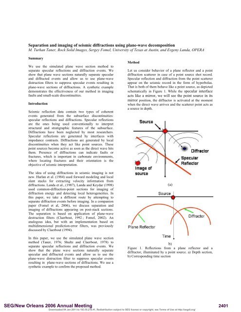
<strong>Separation</strong> <strong>and</strong> <strong>imaging</strong> <strong>of</strong> <strong>seismic</strong> <strong>diffractions</strong> <strong>using</strong> <strong>plane</strong>-<strong>wave</strong> decompositionM. Turhan Taner, Rock Solid Images, Sergey Fomel, University <strong>of</strong> Texas at Austin, <strong>and</strong> Evgeny L<strong>and</strong>a, OPERASummaryWe use the simulated <strong>plane</strong> <strong>wave</strong> section method toseparate specular reflections <strong>and</strong> diffraction events. Weshow that <strong>plane</strong> <strong>wave</strong> sections naturally separate specular<strong>and</strong> diffracted events <strong>and</strong> allow us to use <strong>plane</strong>-<strong>wave</strong>distruction filters to suppress specular events resulting in<strong>plane</strong>-<strong>wave</strong> sections <strong>of</strong> <strong>diffractions</strong>. A synthetic exampledemonstrates the effectiveness <strong>of</strong> our method in <strong>imaging</strong>faults <strong>and</strong> small-scale discontinuities.IntroductionSeismic reflection data contain two types <strong>of</strong> coherentevents generated from the subsurface discontinuities:specular reflections <strong>and</strong> <strong>diffractions</strong>. Specular reflectionsare the ones being used conventionally to interpretstructural <strong>and</strong> stratigraphic features <strong>of</strong> the subsurface.Diffractions have been neglected by most researchers.Specular reflections are generated by interfaces withimpedance contrasts. Diffractions are generated by localdiscontinuities when they act like point sources. Thesepoint sources become active as soon as the direct <strong>wave</strong> hitsthem. Presence <strong>of</strong> <strong>diffractions</strong> can indicate faults orfractures, which is important in carbonate environments,where locating fractures <strong>and</strong> their orientation is theobjective <strong>of</strong> <strong>seismic</strong> interpretation.The idea <strong>of</strong> <strong>using</strong> <strong>diffractions</strong> in <strong>seismic</strong> <strong>imaging</strong> is notnew. Harlan et al. (1984) used forward modeling <strong>and</strong> localslant stacks for extracting velocity information from<strong>diffractions</strong>. L<strong>and</strong>a et al., (1987), L<strong>and</strong>a <strong>and</strong> Keydar (1998)used common-diffraction-point sections for <strong>imaging</strong> <strong>of</strong>diffraction energy <strong>and</strong> detecting local heterogeneities. Inthis paper, we take a different route by attempting toseparate diffraction events before <strong>imaging</strong>. In a companionpaper (Fomel et al, 2006), we discuss separation <strong>and</strong><strong>imaging</strong> <strong>of</strong> <strong>diffractions</strong> appearing on post-stack sections.The separation is based on application <strong>of</strong> <strong>plane</strong>-<strong>wave</strong>destruction filters (Claerbout, 1992 ; Fomel, 2002). Ananalogous idea, but with an implementation based onmultidimensional prediction-error filters, was previouslydiscussed by Claerbout (1994).In this paper, we use the simulated <strong>plane</strong> <strong>wave</strong> sectionmethod (Taner, 1976; Shultz <strong>and</strong> Claerbout, 1978) toseparate specular reflections <strong>and</strong> diffraction events. Weshow that the <strong>plane</strong> <strong>wave</strong> sections naturally separatespecular <strong>and</strong> diffracted events <strong>and</strong> allow us to use the<strong>plane</strong>-<strong>wave</strong> distruction filter to suppress specular eventsresulting in <strong>plane</strong>-<strong>wave</strong> sections <strong>of</strong> <strong>diffractions</strong>. We use asynthetic example to confirm the proposed method.MethodLet us consider behavior <strong>of</strong> a <strong>plane</strong> reflector <strong>and</strong> a pointdiffraction scatterer in case <strong>of</strong> a point source shot record.Specular reflection <strong>and</strong> diffraction from the point scattererappear on the <strong>seismic</strong> record in the form <strong>of</strong> hyperbolas.That is both <strong>of</strong> them behave like a point source, as depictedschematically in Figure 1. While the specular interfaceacts like a mirror, we will see the point source in itsmirror position, the diffractor is activated at the momentwhen the direct <strong>wave</strong> arrives <strong>and</strong> the scatterer point acts asa source in depth.(a)b)Figure 1. Reflections from a <strong>plane</strong> reflector <strong>and</strong> adiffractor, illuminated by a point source. a) Depth section,b) Corresponding time sectionSEG/New Orleans 2006 Annual MeetingDownloaded 04 Jan 2011 to 193.55.218.41. Redistribution subject to SEG license or copyright; see Terms <strong>of</strong> Use at http://segdl.org/2401
Prestack diffraction separationIf we activate a <strong>plane</strong> <strong>wave</strong> source, the reflected event froma <strong>plane</strong> specular reflector creates a <strong>plane</strong> <strong>wave</strong>, while thepoint diffractor behaves the same way as in the previouscase <strong>and</strong> acts like a point source. (Figure 2)with marine case (single end observation geometry) thecable end creates an edge effect: semi spherical <strong>wave</strong> field,we wish to attenuate. To do it, we can use the reciprocityprinciple <strong>and</strong> create an artificial split-spread shot record bysorting the data to CMP domain, replicating the CMP datato the opposite sign <strong>of</strong>fsets, <strong>and</strong> sorting it back to the shotrecords.When we sum a split spread shot record horizontally, wesimulate a <strong>plane</strong> <strong>wave</strong> propagating vertically downward atthe inception. If we shift the traces linearly beforesummation, we generate a dipping <strong>plane</strong> <strong>wave</strong>. Byrepeating summations with various dips, we actuallygenerate a τ-p section corresponding to our shot record, orthe Radon transform estimate. There are many proceduresto compute the Radon transform (Gardner <strong>and</strong> Lu, 1991),<strong>and</strong> we do not discuss them here.(a)(b)Figure 2. Plane reflector <strong>and</strong> a diffractor reflections , asilluminated by a <strong>plane</strong> source <strong>wave</strong>: a) Depth section,b) Corresponding time section.To generate <strong>plane</strong> <strong>wave</strong> sections from a point source<strong>seismic</strong> data we invoke two basic laws: superposition <strong>and</strong>reciprocity. Reciprocity helps us exchange receiver <strong>and</strong>source positions. By the superposition we can combinedifferent <strong>seismic</strong> records together to simulate <strong>plane</strong>-<strong>wave</strong>records as if all the sources were exploded simultaneously.Plane <strong>wave</strong> decomposition (Taner, 1976) can beschematically described as follows. Taking one commonshot record <strong>and</strong> summing the traces horizontally withoutany time delay we simulate a trace which we would obtainif we exploded simultaneously many sources at the receiverlocations <strong>and</strong> record the reflected data at the sourceposition. Repeating this procedure for several shot recordswe can simulate <strong>plane</strong>-<strong>wave</strong> source record. When we dealMore details about <strong>plane</strong>-<strong>wave</strong> decomposition aredescribed by Yilmaz <strong>and</strong> Taner (1994). A section <strong>of</strong> aconstant <strong>plane</strong>-<strong>wave</strong> slope p illuminates the subsurfacewith a specific angle at the surface. On these constant psections we will have specular reflections appear as quasilinearcontinuous events <strong>and</strong> diffracted <strong>wave</strong>s will appearin the quasi-hyperbolic shaped traveltimes (Green’sfunctions). We can now use the <strong>plane</strong>-<strong>wave</strong> destructionfilter (Fomel, 2002) to suppress the specular events <strong>and</strong> toobtain a section containing mainly diffracted events <strong>and</strong>residual specular reflection energy. Since the resultingtraces are Radon transformed traces, their S/N ratio shouldbe better than the original traces in the time domain. Thescattering objects (faults, fractures etc.) will be imaged onthe migrated (time or depth) common p sections.In summary, our flow for <strong>wave</strong>field separation is:1) Generate split spread common source records;2) Plane-<strong>wave</strong> decompose each common sourcerecord;3) Sort into constant p sections;4) Plane-<strong>wave</strong> destruction filter on constant psections;5) Velocity analysis for migration;6) Migrate individual p sections <strong>and</strong> then sum toproduce a prestack migration image.ExampleFigure 3a shows a synthetic single end shot gather for amodel containing numerous sharp structural discontinuitiesproducing numerous diffraction events. To perform <strong>plane</strong><strong>wave</strong>decomposition for shot records we constructed a splitspread observation geometry <strong>using</strong> the reciprocity as it isdescribed above (Figure 3b). Figure 4a shows <strong>plane</strong>-<strong>wave</strong>decomposed shot gather <strong>and</strong> Figure 4b illustrates the sameshot gather reconstructed by an inverse Radon transform.SEG/New Orleans 2006 Annual MeetingDownloaded 04 Jan 2011 to 193.55.218.41. Redistribution subject to SEG license or copyright; see Terms <strong>of</strong> Use at http://segdl.org/2402
Prestack diffraction separationRepeating <strong>plane</strong>-<strong>wave</strong> decomposition for all shot recordswe obtain common p section for entire line. Figure 5 <strong>and</strong> 6show two common p sections for different p parameter: 0,0.5. Applying the <strong>plane</strong>-<strong>wave</strong> distruction filter to each <strong>of</strong>the total <strong>wave</strong>field sections (left) we obtain thecorresponding sections containing mostly diffractionenergy (right). It is interesting to observe that some <strong>of</strong> theseparated events in the deeper part <strong>of</strong> the sections areactually not <strong>diffractions</strong> but triplications <strong>of</strong> the propagating<strong>plane</strong> <strong>wave</strong> caused by lateral velocity variations.Figure 5. Common p (p=0) section <strong>of</strong> the total <strong>wave</strong>field(left) <strong>and</strong> after <strong>wave</strong>field separation (right).Figure 3. Single ended (left) <strong>and</strong> split-spread (right) shotgather.Figure 6. Common p (p=0.5) section <strong>of</strong> the total <strong>wave</strong>field(left) <strong>and</strong> after <strong>wave</strong>field separation (right)Figure 4. Radon transformed (left) <strong>and</strong> reconstructed byinverse Radon transform shot gatherSorting back to shot domain <strong>and</strong> applying inverse Radontransform we obtain <strong>seismic</strong> records containing diffractionevents <strong>and</strong> residual specular reflection energy. Theserecords now can be used for velocity model estimating,time or depth <strong>imaging</strong> <strong>and</strong> should emphasize sharpdiscontinuities <strong>of</strong> the subsurface. Figure 7 shows prestackdepth migrated image <strong>of</strong> the total <strong>wave</strong>field (a) <strong>and</strong>“<strong>diffractions</strong> only” components (b). Most <strong>of</strong> the scatteringobjects which are masked on the conventional section (a)can be observed on the “<strong>diffractions</strong> only” section (b).SEG/New Orleans 2006 Annual MeetingDownloaded 04 Jan 2011 to 193.55.218.41. Redistribution subject to SEG license or copyright; see Terms <strong>of</strong> Use at http://segdl.org/2403
Prestack diffraction separationSeparated <strong>and</strong> imaged <strong>diffractions</strong> can provide valuableinformation about small-scale subsurface features such asfaults, fractures, rough salt boundaries, channels, etc.Although we show only a 2-D example in this paper, ourmethod is applicable to 3-D <strong>plane</strong>-<strong>wave</strong> decompositionssuch as those recently described by Zhang et al (2005).ReferencesClaerbout, J. F., 1992, Earth sounding analysis: Processingversus inversion: Blackwell.Claerbout, J. F., 1994, Applications <strong>of</strong> two- <strong>and</strong> threedimensionalfiltering: 64th Ann. Internat. Mtg, Soc. <strong>of</strong>Expl. Geophys., 1572–1575.(a)Fomel, S., 2002, Applications <strong>of</strong> <strong>plane</strong>-<strong>wave</strong> destructionfilters: Geophysics, 67, 1946–1960.Fomel, S., E. L<strong>and</strong>a, <strong>and</strong> M. T. Taner, 2006, Post-stackvelocity analysis by separation <strong>and</strong> <strong>imaging</strong> <strong>of</strong> <strong>seismic</strong><strong>diffractions</strong>: 76th Ann. Internat. Mtg, Soc. <strong>of</strong> Expl.Geophys., submitted.Gardner, G. F. <strong>and</strong> L. Lu, eds., 1991, Slant-stackprocessing: Soc. Of Expl. Geophys.Harlan, W. S., J. F. Claerbout, <strong>and</strong> F. Rocca, 1984,Signal/noise separation <strong>and</strong> velocity estimation:Geophysics, 49, 1869-1880.L<strong>and</strong>a, E., V. Shtivelman, <strong>and</strong> B. Gelchinsky, 1987, Amethod for detection <strong>of</strong> diffracted <strong>wave</strong>s on common-<strong>of</strong>fsetsections: Geophysical Prospecting, 35, 359-373.(b)Figure 7. Prestack depth migration <strong>of</strong> the full <strong>wave</strong>-field (a)<strong>and</strong> the separated <strong>diffractions</strong> (b).ConclusionsThe objective <strong>of</strong> this paper is to show that <strong>plane</strong>-<strong>wave</strong>constant p sections contain diffraction patterns that directlyobey the <strong>wave</strong> equation together with specular reflectors. Incontrast to point source sections, <strong>plane</strong>-<strong>wave</strong> sectionscontain specular events that appear as simply shapedlaterally continuous events. Diffracted events appear in theform <strong>of</strong> foc<strong>using</strong> operators with a delay equal to the traveltime from the source <strong>wave</strong> origin to the point scatterer.This observation allowed us to develop a method fordiffraction separation <strong>and</strong> <strong>imaging</strong> based on applying<strong>plane</strong>-<strong>wave</strong> destruction filtering on <strong>plane</strong>-<strong>wave</strong> sections.L<strong>and</strong>a, E. <strong>and</strong> S. Keydar, 1998, Seismic monitoring <strong>of</strong>diffracted images for detection <strong>of</strong> local heterogeneities:Geophysics, 63, pp 1093Schultz, P. S. <strong>and</strong> J.F. Claerbout, J. F., 1978, Velocityestimation <strong>and</strong> downward continuation by <strong>wave</strong>frontsynthesis: Geophysics, 43, 691-714.Taner, M. T., 1976, Simplan: similated <strong>plane</strong>-<strong>wave</strong>exploration, 46th Ann. Internat. Mtg., Soc. Expl.Geophys., 186-187.Yilmaz, O. <strong>and</strong> M. T. Taner, 1994, Discrete <strong>plane</strong>-<strong>wave</strong>decomposition by least-mean-square-error method:Geophysics, 59, 973-982.Zhang, Y., J. Sun, C. Notfors, S. H. Gray, L. Chernis, <strong>and</strong>J. Young, 2005, Delayed-shot 3D depth migration:Geophysics, 70, E21-E28.SEG/New Orleans 2006 Annual MeetingDownloaded 04 Jan 2011 to 193.55.218.41. Redistribution subject to SEG license or copyright; see Terms <strong>of</strong> Use at http://segdl.org/2404