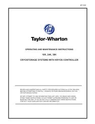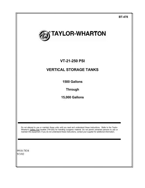
VT-21-250 PSI VERTICAL STORAGE TANKS - Taylor-Wharton
VT-21-250 PSI VERTICAL STORAGE TANKS - Taylor-Wharton
VT-21-250 PSI VERTICAL STORAGE TANKS - Taylor-Wharton

You also want an ePaper? Increase the reach of your titles
YUMPU automatically turns print PDFs into web optimized ePapers that Google loves.
BT-478<strong>VT</strong>-<strong>21</strong>-<strong>250</strong> <strong>PSI</strong><strong>VERTICAL</strong> <strong>STORAGE</strong> <strong>TANKS</strong>1500 GallonsThrough15,000 GallonsDo not attempt to use or maintain these units until you read and understand these instructions. Refer to the <strong>Taylor</strong>-<strong>Wharton</strong>’s Safety First booklet (TW-202) for handling cryogenic material. Do not permit untrained persons to use ormaintain this equipment. If you do not understand these instructions, contact your supplier for additional information.9918-78349/3/02
Extreme Cold - Cover Eyes and Exposed SkinAccidental contact of liquid oxygen or cold issuing gas with the skin or eyes may cause a freezinginjury similar to frostbite. Handle the liquid so that it won't splash or spill. Protect your eyes andcover the skin where the possibility of contact with the liquid, cold pipes and cold equipment, or thecold gas exists. Safety goggles or a face shield should be worn if liquid ejection or splashing mayoccur or cold gas may issue forcefully from equipment. Clean, insulated gloves that can be easilyremoved and long sleeves are recommended for arm protection. Cuffless trousers should be wornoutside boots or over the shoes to shed spilled liquid. If clothing should be splashed with liquidoxygen or otherwise saturated with the gas, air out the clothing immediately, removing it if possible.Such clothing will be highly flammable and easily ignited while the concentrated oxygen remains,and should not be considered safe for at least 30 minutes.Replacement Parts Must be Suitable for Oxygen ServiceMany materials, especially some non-metallic gaskets and seals, constitute a combustion hazardwhen in oxygen service, although they may be acceptable for use with other cryogenic liquids.Make no substitutions for recommended spare parts. Also, be sure all replacement parts arethoroughly "Cleaned For Oxygen Service" in accordance with Compressed Gas Association (CGA)Pamphlet G-4.1 "Cleaning for Oxygen Service" or equivalent industrial cleaning specifications.Observe Safety Codes When Locating Oxygen EquipmentBefore locating oxygen equipment, become thoroughly familiar with National Fire ProtectionAssociation (NFPA) Standard No. 50, "Bulk Oxygen Systems", and with all federal, state and localsafety codes. The NFPA Standard covers the general principles recommended for the installation ofbulk oxygen systems on industrial and institutional consumer premises.CAUTION: When installing field fabricated piping, make certain a suitable safety valve isinstalled in each section of piping between shut-off valves.For more detailed information concerning safety precautions and safe practices to be observed when handlingcryogenic liquids consult CGA pamphlet P-12 "Handling Cryogenic Liquids" available from the CompressedGas Association, 1235 Jefferson Davis Highway, Arlington, Va. 22202.5
SAFETY PRECAUTIONS FOR LIQUID NITROGENNitrogen is an inert, colorless, odorless, and tasteless gas, which makes up four-fifths of the air youbreathe. Liquid nitrogen is obtained by cooling air until it becomes a liquid and then removing theoxygen, which makes up the other fifth of the air. Liquid nitrogen is at a temperature of 320 degreesbelow zero Fahrenheit (-196°C) under normal atmospheric pressure.Extreme Cold - Cover Eyes and Exposed SkinAccidental contact of liquid nitrogen or cold issuing gas with the skin or eyes may cause a freezinginjury similar to frostbite. Handle the liquid so that it won't splash or spill. Protect your eyes andcover the skin where the possibility of contact with the liquid, cold pipes and cold equipment, or thecold gas exists. Safety goggles or a face shield should be worn if liquid ejection or splashing mayoccur or cold gas may issue forcefully from equipment. Clean insulated gloves that can be easilyremoved and long sleeves are recommended for arm protection. Cuffless trousers should be wornoutside boots or over the shoes to shed spilled liquid.Keep Equipment Area Well VentilatedAlthough nitrogen is non-toxic and non-flammable, it can cause asphyxiation in a confined areawithout adequate ventilation. Any atmosphere, which does not contain enough oxygen forbreathing, can cause dizziness, unconsciousness, or even death. Nitrogen being colorless, odorless,and tasteless cannot be detected by the human senses and will be inhaled normally as if it were air.Without adequate ventilation, the expanding nitrogen will displace the normal air without warningthat a non-life-supporting atmosphere is present. Store liquid containers outdoors or in other wellventilatedareas.Dispose of Waste Liquid Nitrogen SafelyDispose of waste liquid nitrogen out-of-doors where its cold temperature cannot damage floors ordriveways and where it will evaporate rapidly. An outdoor pit filled with clean sand or gravel willevaporate liquid nitrogen safely and quickly.CAUTION: When installing field fabricated piping, make certain a suitable safety valve isinstalled in each section of piping between shut-off valves.For more detailed information concerning safety precautions and safe practices to beobserved when handling cryogenic liquids consult CGA pamphlet P-12 "HandlingCryogenic Liquids" available from the Compressed Gas Association, 1235 Jefferson DavisHighway, Arlington, VA 22202.NOTE:Argon is an inert gas whose physical properties are very similar to those of nitrogen. For handling ofliquid argon, follow the safe practices described for the handling and use of liquid nitrogen.6
Vacuum System ComponentsINSTALLATIONHANDLINGDimension and connection data for the <strong>VT</strong>-<strong>250</strong> tanks can be found on the applicable GeneralArrangement Drawing in this manual. Additional copies of these drawings may be requested fromthe factory. Please include information on the tank model number and part number in makingrequests for this drawing. The drawing part number is listed in the applicable Specification chart inthis manual.Tank installation is the customer's responsibility. The tank is shipped in the horizontal position. Ifthe tank is secured on temporary wooden cradles, the cradles must be removed prior to erection ofthe tank. Make certain the foundation used for the tank is designed for the conditions at theinstallation site, and that it is suitable for the tank weight. Refer to local codes for recommendedfoundation specifications. Employ experienced personnel to move and install the tank. Ensure that11
Requirements for Installation and Use Within New York City Fire DepartmentJurisdictionOwners and installers within NYCFD jurisdiction are required to meet the following guidelinesconcerning the installation and use of <strong>VT</strong>-<strong>250</strong> design bulk tanks.• The installation and use of the vessel must comply with all applicable New York City Codes,Rules, and Regulations.• After installation, the vessel shall not be filled until the required New York City FireDepartment storage permit has been issued.• The owner / installer shall be in compliance with all of the manufacturer’s installation andmaintenance procedures and limitations.• The liquid level gauge is to be marked to indicate the maximum permissible fill level for therespective gas being utilized.• The vessel fill capacity shall be limited to comply with CGA-341 (Standard for InsulatedCargo Tank Specification for Cryogenic Liquids).• The vessel is for outdoor use only, will be placed in areas acceptable to NYCFD, and must beprotected from vandalism.• Changes in ownership or owner’s name must be reported to NYCFD in writing.WARNING: Failure to comply with the conditions of Certificate of Approval #4956 canbe the basis for being subjected to enforcement action that can include finesand imprisonment.13
Note: Refer to General Arrangement Drawing for Critical Weight and Dimensional DataFigure 1: Rigging for <strong>VT</strong>-6000 through <strong>VT</strong>-1300015
Note: Refer to General Arrangement Drawing for Critical Weight and Dimensional DataFigure 1: Rigging for <strong>VT</strong>-1500016
OPERATIONThese instructions are for experienced operators. Before operating the storage tank becomethoroughly familiar with the safety precautions in this manual and in reference publications.Make certain all applicable provisions set forth in the Installation section have been followedbefore placing a tank in operation. Study the Flow Diagram, Tank Elevation and End Views onthe applicable General Arrangement Drawing located in the back of this manual and theFunctional Description section of this manual. Know the location and function of all tankcomponents.PURGE PROCEDUREBefore placing a tank in service, determine the level of purity in the pressure vessel. If pressurevessel contents purity is unacceptable, perform a product purge to reduce contaminants. Thefollowing procedure is recommended for most application:1. Attach the liquid purge product source to tank FILL CONNECTION (CN-1). Productdelivery pressure should be approximately 100 psig (6.9 bar/690 kPa).CAUTION:A positive pressure must always be maintained in the tank during the purgeprocedure to prevent drawing atmospheric contaminants back into the tank.2. Close all valves except ISOLATION VALVES (HCV-8, HCV-10), PRESSUREBUILDING ISOLATION VALVE (HCV-3), and PRESSURE BUILDING ISOLATIONVALVE (HCV-11).3. Open TANK BLOWDOWN VALVE (HCV-12) and vent inner vessel to 5 psig (0.34 bar/34kPa) as indicated on the tank PRESSURE GAUGE, INNER VESSEL (PI-1). If not suppliedwith the tank this PRESSURE GAUGE, INNER VESSEL must be installed by theCustomer. Close TANK BLOWDOWN VALVE (HCV-12).4. Open BOTTOM FILL VALVE (HCV-1) slightly to allow liquid to flow slowly into bottomof tank. Flow must be gradual enough to allow the liquid to vaporize in the bottom fill lineand PRESSURE BUILDING COIL (PBC-1) so the pressure builds up in the inner vessel.Momentarily open TOP FILL VALVE (HCV-2) to flood the exposed section of line, thenclose valve.5. When tank PRESSURE GAUGE, INNER VESSEL (PI-1) indicates maximum desiredpurge pressure, close the liquid supply source. Close PRESSURE BUILDING ISOLATIONVALVE (HCV-3).6. Cautiously drain liquid from the tank by opening the AUXILIARY LIQUID VALVE (HCV-17) if provided or through the FILL LINE HOSE DRAIN VALVE (HCV-7). The valveshould be opened slowly to avoid splashing of liquid. When vapor appears from the valve,the liquid has been drained from the tank.7. Close AUXILIARY LIQUID VALVE (HCV-17) or FILL LINE HOSE DRAIN VALVE(HCV-7) opened in step 6.17
8. Tanks with factory supplied LIQUID LEVEL GAUGE: - After liquid has drained from thetank, close ISOLATION VALVES (HCV-8, HCV-10). The EQUALIZATION VALVE(HCV-9) should be opened just before closing ISOLATION VALVES (HCV-8, HCV-10) toprevent damage to the LIQUID LEVEL GAUGE (LL-1). Carefully loosen the adapters onboth sides of the LIQUID LEVEL GAUGE to relieve pressure. Disconnect the instrumentlines and fully open ISOLATION VALVES (HCV-8, HCV-10). Visually check the resultantgas streams for signs of moisture. Vent lines for approximately two minutes. If no moistureis evident, close the ISOLATION VALVES (HCV-8, HCV-10). If moisture is evident,continue venting until the stream is free of moisture.Tanks without factory supplied LIQUID LEVEL GAUGE: - Prior to installing components toISOLATION VALVES (HCV-8, HCV-10) visually check the resultant gas streams for signsof moisture by fully opening ISOLATION VALVES (HCV-8, HCV-10). Vent lines forapproximately two minutes. If no moisture is evident, close ISOLATION VALVES (HCV-8, HCV-10). If moisture is evident, continue venting until the stream is free of moisture.CAUTION:NOTE:Do not look directly into the tank lines. Bodily injury could occur.Carefully open gauge valves since some residual liquid may have remained intank or the instrument lines.9. Open PRODUCT SUPPLY VALVE (HCV-13) and AUXILIARY LIQUID VALVE (HCV-17) if provided to check for moisture as in Step 8.10. Open TANK BLOWDOWN VALVE (HCV-12) and TRYCOCK VALVE (HCV-4) andcheck for moisture as in step 8.11. Repeat purge procedures 2 through 11 until acceptable product purity is achieved.12. Reconnect the LIQUID LEVEL GAUGE (installed by user), open ISOLATION VALVES(HCV-8, HCV-10) and close EQUALIZATION VALVE (installed by user).13. After completion of tank purge, make sure that all valves are closed except the GAUGEISOLATION VALVES (HCV-8, HCV-10).FILLING A WARM TANKPerform the following steps to fill a tank for the first time or when returning a tank to service after ithas been emptied and allowed to warm.1. Close all valves except GAUGE ISOLATION VALVES (HCV-8) and (HCV-10).2. Check the name of the contents on the supply source against the product name on the tank tobe certain that the proper product is being transferred into the tank.3. Connect supply source fill hose to tank FILL CONNECTION (CN-1). Make certainconnection is leak tight. Purge the fill hose.18
4. Fully open tank BOTTOM FILL VALVE (HCV-1), PRESSURE BUILDING ISOLATIONVALVES (HCV-3) & (HCV-11) start tank fill. Open tank TOP FILL VALVE (HCV-2) oneturn. Adjust the two FILL VALVES (HCV-1, HCV-2) as required to maintain normal tankoperating pressure as shown on tag attached to tank PRESSURE GAUGE, INNER VESSEL(installed by user).NOTE:Filling through the BOTTOM FILL VALVE (HCV-1) will increase tankpressure since gas in the vapor space is compressed, whereas filling throughthe TOP FILL VALVE (HCV-2) decreases tank pressure since gas in theullage space is cooled and re-liquefied.5. Open tank FULL TRYCOCK valve (HCV-4) when tank LIQUID LEVEL GAUGE(supplied by customer) indicates 3/4 full.6. When liquid spurts from tank FULL TRYCOCK VALVE (HCV-4), close supply sourcedelivery valve to stop fill. Close tank BOTTOM FILL VALVE (HCV-1) and FULLTRYCOCK valve (HCV-4).7. When residual liquid in the fill hose vaporizes, close tank TOP FILL VALVE (HCV-2).CAUTION: To avoid injury, do not touch fill hose or connections with bare hands.During filling, these parts are cooled to extremely low temperatures.8. Open FILL LINE DRAIN VALVE (HCV-7) to relieve fill hose pressure. Close FILL LINEDRAIN VALVE (HCV-7).9. When pressure is released disconnect fill hose.NORMAL OPERATIONDuring normal operation, tank pressure forces product through the siphon withdrawal line and theVAPORIZER INLET VALVE (HCV-13) to an external vaporizer that feeds the user's pipeline. Tocompensate for lowering of tank pressure as product is withdrawn, the PRESSURE BUILDINGREGULATOR (PCV-1) allows a regulated amount of liquid to flow to the PRESSURE BUILDINGCOIL (PBC-1). Vaporized liquid is returned to the tank to provide the driving force foruninterrupted pipeline withdrawal. During periods when the withdrawal rate is low and tankpressure rises above the set point of ECONOMIZER REGULATOR (PCV-2), the economizercircuit becomes operational. Liquid withdrawal is interrupted and gas flows through theECONOMIZER REGULATOR (PCV-2) to the vaporizer thereby supplying the pipeline with gasthat would otherwise be vented to the atmosphere.To prepare the tank for normal product withdrawal, open the following valves:PRESSURE BUILDING ISOLATION VALVE (HCV-11),PRESSURE BUILDING ISOLATION VALVE (HCV-3),20
LIQUID LEVEL GAUGE ISOLATION VALVES (HCV-8) & (HCV-10)PRODUCT SUPPLY VALVE (HCV-13),All other valves should be closed.TAKING A TANK OUT OF SERVICESchedule shutdown operation to coincide with low liquid level in the tank. If a largequantity of liquid is in the tank, drain it into a trailer for use elsewhere or for disposal at a safelocation. For tanks so equipped, small quantities of liquid can be vaporized by the PRESSUREBUILDING COIL (PBC-1) and vented through the TANK BLOWDOWN VALVE (HCV-12),provided appropriate safety precautions are taken.For shutdowns of short duration, retain residual liquid in the tank. Close all valves excepttank LIQUID LEVEL GAUGE ISOLATION VALVES (HCV-8) and (HCV-10).For shutdowns of a prolonged duration, perform the following steps.<strong>TANKS</strong> IN OXYGEN SERVICE1. Drain liquid from tank. Open the TANK BLOWDOWN VALVE (HCV-12) and reducetank pressure to atmospheric. Close the TANK BLOWDOWN VALVE (HCV-12).2. Connect a source of warm nitrogen gas to tank FILL CONNECTION (CN-1). Admitnitrogen purge gas through tank BOTTOM FILL VALVE (HCV-1). Vent tank through theTANK BLOWDOWN VALVE (HCV-12). Two or three times during purge, close theTANK BLOWDOWN VALVE (HCV-12) and build tank pressure to about 10 psig (0.7bar/70 kPa). Release pressure and continue purge.3. Open the tank TRYCOCK VALVE (HCV-4) and the PRESSURE BUILDINGISOLATION VALVE (HCV-3) and check exit gas with a nitrogen gas analyzer. Allow onehour between samples reading for the gas to adequately mix. Discontinue purge when onlynitrogen gas is indicated. Close tank TRYCOCK VALVE (HCV-4).4. Close the TANK BLOWDOWN VALVE (HCV-12). Build tank pressure to 20 psig(1.38 bar/138 kPa). Close tank BOTTOM FILL VALVE (HCV-1). Disconnect nitrogen gashose from tank FILL CONNECTION (CN-1).5. Warm tank inner vessel before shipping to a new location.<strong>TANKS</strong> IN NITROGEN/ARGON SERVICE1. Drain liquid product from tank. Open tank TANK BLOWDOWN VALVE (HCV-12) andreduce tank pressure to 20 (1.4 bar/140 kPa). Close tank TANK BLOWDOWN VALVE(HCV-12).2. Warm tank inner vessel before moving to a new location.<strong>21</strong>
MAINTENANCEGENERALThe need for maintenance usually becomes apparent from inspection of the tank before filling,routine observation during and after filling, and indications of improper operation. Typical troubleindications would be unusually high or low tank or pipeline pressure, leakage from valves or pipingconnections, and excessive venting through relief valves. Prompt action to correct damage ormalfunction is required to assure reliable operation. Keep a permanent log of all inspections,vacuum readings, and repairs performed. Such a log can be valuable in evaluating tank performanceand scheduling maintenance.Always observe the safety precautions at the front of this manual and follow the instructions given inthis section. Before working on the tank or piping system, isolate the piping section to be repairedfrom the tank, and relieve pressure on the component or piping.Do not allow unqualified persons to attempt repairs on this equipment. Field repairs to instrumentsand controls must be made by a qualified instrument specialist. Refer to the Trouble-Remedy Guidein this manual for assistance in troubleshooting.Make certain all parts that will come in contact with cryogenic liquid or gaseous product have beencleaned for in conformance with CGA Pamphlet G-4.1, "Cleaning Equipment for Oxygen Service",or other equivalent standard. If parts are purchased cleaned for oxygen service, they should besuitably packaged to prevent contamination.LEAK TESTINGAfter making repairs requiring disassembly or part replacement, leak test all valves or piping jointsthat were taken apart and reconnected. Apply the leak detector to the test surface per themanufacturer's instructions. Large leaks instantly form large bubble clusters, while fine leaksproduce white foam that builds up more slowly. All leaks must be repaired and retested before thetank is returned to service.WARNING: For O 2 System Users: Residue of leak detectors can be flammable. All surfacesto which the leak detector solutions have been applied must be adequatelyrinsed with potable water to remove all traces of residue. Reference CGA G-4.Section 4.9.HAND VALVESThe most common trouble with manual valves will be leakage at the stem packing. Packing leaksare usually indicated by frost or ice accumulation more than half way up the valve stem extension.If packing leakage cannot be stopped by tightening, add or replace packing. Use preformed packing,which can be ordered from the valve manufacturer.Standard maintenance practices apply to the replacement of seats and discs in globe and gate valves.Replacement parts may be ordered from the valve manufacturer. Provide the factory part numbermarked on the valve for identification.22
CONTROL VALVESThese tanks have two automatic valves that control operating pressures.The PRESSURE BUILDING REGULATOR (PCV-1) opens on falling tank pressure and closes onrising pressure. This valve is factory set at 150 psig (10.34 bar/1034 kPa).The ECONOMIZER BACK PRESSURE REGULATOR (PCV-2) is a backpressure device thatopens on rising tank pressure and closes on falling pressure. This valve is factory set at 165 psig(11.37 bar/1137 kPa).The factory setting of the control valves may be field adjusted. The ECONOMIZER BACKPRESSURE REGULATOR (PCV-2) should be set to open at a pressure above the shut-off pressureof the pressure building circuit.Before attempting repair of either of the control valves, isolate and depressurize the valves byclosing the PRESSURE BUILDING ISOLATION VALVE (HCV-3), PRESSURE BUILDINGISOLATION VALVE (HCV-11) and ECONOMIZER ISOLATION VALVE (HCV-14). Turn theECONOMIZER BACK PRESSURE REGULATOR (PCV-2) set screw counterclockwise to the endof its adjustment. Open TOP AND BOTTOM FILL VALVES (HCV-1 / HCV-2). Vent pressure byopening FILL DRAIN VALVE (HCV-7). Close TOP AND BOTTOM FILL VALVES (HCV-1 /HCV-2) and FILL DRAIN VALVE (HCV-7). Carefully loosen the PRESSURE RELIEF VALVE(TSV-4) to release any pressure in the line. When repairs are complete, purge lines and retighten thePRESSURE RELIEF VALVE (TSV-4) and pressure test all joints that were disassembled.Order replacement parts from the valve manufacturer. Be sure to give all information on the valvenameplate, including the factory Part Number, as well as <strong>Taylor</strong>-<strong>Wharton</strong> part number listed in the"Replacement Parts" provided in this manual to ensure receiving the correct parts for these specialvalves.RESETTING CONTROL VALVESUse the following procedures to change control valve settings or to readjust the valves aftercompleting repairs of the valves.The PRESSURE BUILDING REGULATOR (PCV-1) should be set so that tank pressure is heldabout 5 psig (0.34 bar / 34 kPa) above the desired delivery pressure. The ECONOMIZER BACKPRESSURE REGULATOR (PCV-2) should be set at least 10 psig (0.7 bar / 70 kPa) above thesetting of the PRESSURE BUILDING REGULATOR (PCV-1). If both controls are to be reset, setthe PRESSURE BUILDING REGULATOR (PCV-1) before setting the ECONOMIZER BACKPRESSURE REGULATOR (PCV-2).23
NOTE:The tank must contain liquid for setting control valves. The ECONOMIZERREGULATOR (PCV-2) must be adjusted while product is being withdrawnthrough the product withdrawal line.SETTING PRESSURE BUILDING REGULATOR (PCV-1):1. If tank pressure is below desired setting: Loosen pressure screw locknut on REGULATOR(PCV-1). With PRESSURE BUILDING ISOLATION VALVE (HCV-3) and PRESSUREBUILDING ISOLATION VALVE (HCV-11) open, gradually open REGULATOR (PCV-1)by turning pressure screw in (clockwise) to build tank pressure to 5 psig (0.34 bar / 34 kPa)above the desired delivery pressure. Note that the pressure screw must be adjusted in smallincrements, allowing sufficient time for tank pressure to stabilize each time the screw isturned. When desired set point is reached, tighten pressure screw locknut.2. If tank pressure is above desired setting: Loosen pressure screw locknut and turn pressurescrew out (counterclockwise) to end of adjustment range. Open TANK BLOWDOWNVALVE (HCV-12) and vent until tank pressure is 5 psig (0.34 bar / 34 kPa) above desireddelivery pressure. With PRESSURE BUILDING ISOLATION VALVE (HCV-3) andPRESSURE BUILDING ISOLATION VALVE (HCV-11) open, slowly turn pressure screwin (clockwise) until REGULATOR (PCV-1) just opens as indicated by cooling ofdownstream pipe (at REGULATOR outlet). Tighten pressure screw locknut.SETTING ECONOMIZER BACK PRESSURE REGULATOR (PCV-2):1. Loosen ECONOMIZER BACK PRESSURE REGULATOR (PCV-2) pressure screwlocknut and turn pressure screw in (clockwise) to end of adjustment range. Check that thePRESSURE BUILDING ISOLATION VALVES (HCV-3) and (HCV-11) are open.2. a. If tank pressure is below desired set point: Build pressure by opening both fillvalves. Note that the fill connection must be securely blanked off. As tank pressureincreases to desired set point-- at least 10 psig (0.7 bar / 70 kPa) above setting ofPRESSURE BUILDING REGULATOR (PCV-1) close BOTTOM FILL VALVE(HCV-1). When liquid in line vaporizes, close the TOP FILL VALVE (HCV-2).Relieve any residual pressure by momentarily opening HOSE DRAIN VALVE(HCV-7).b. If tank pressure is above desired set point: Open TANK BLOWDOWN VALVE(HCV-12) and vent until tank pressure is at desired set point -- at least 10 psi (0.7 bar/ 70 kPa) above setting of PRESSURE BUILDING REGULATOR (PCV-1).24
3. With tank pressure at desired ECONOMIZER BACKPRESSURE REGULATOR (PCV-2)set point, slowly turn pressure screw out (counterclockwise) until valve just opens asindicated by cooling of pipe between the ECONOMIZER BACKPRESSUREREGULATOR (PCV-2) and the ECONOMIZER ISOLATION VALVE (HCV-14).INNER VESSEL AND PIPING SAFETY DEVICESThese tanks are equipped with a dual safety device manifold that permits servicing of one set ofsafety devices while the other set is in service.If a pressure vessel RUPTURE DISC (PSE-1A,PSE-1B) ruptures, determine and correct the causeof the rupture before replacing the device. This device should be replaced annually as a preventivemaintenance procedure. The bursting disc on this tank is a sealed assembly that must be replaced asa unit.Main SAFETY VALVES (PSV-1A,PSV-1B) that leak or fail to operate at the set pressure should bereplaced immediately. Repair and recalibration of these valves should only be done by experiencedpersonnel with proper equipment. Return the valves to the manufacturer or to an ASME approvedrepair station for overhaul or recalibration.Replace RELIEF VALVE (TSV-2, -3, -4) when leakage or improper functioning occurs. Do notattempt to repair or reseat these components since they are of the throw-away type.PRESSURE AND LIQUID LEVEL GAUGESThe major cause of malfunctioning tank TANK PRESSURE GAUGE (PI-1), or LIQUID LEVELGAUGE (LL-1) is an open EQUALIZATION VALVE (HCV-9) or leakage in the gauge lines.Refer to the Trouble-Remedy Guide in this manual for maintenance procedure. If the problem is notreadily corrected, replace the gauge with a spare. Return the defective gauge to the manufacturer forrepair. Include a description of the difficulty encountered.25
CASING VACUUM MAINTENANCECHECKING VACUUMSome vacuum deterioration may occur over an extended period of time due to out gassing ofmaterials within the vacuum space or from leakage. A history of vacuum readings taken over aperiod of time can be valuable when evaluating tank performance and scheduling maintenance work.To detect vacuum deterioration, periodic measurement of the tank vacuum is recommended. Athermocouple-type VACUUM GAUGE TUBE (VR-1), located on the lower head of the tank, isprovided for this purposeTo check tank vacuum perform the following steps:1. Remove the protective plastic cap from the gauge tube connector.2. Connect a Hastings-Raydist Model No. TV-4A or <strong>VT</strong>-6 Vacuum Gauge to theVACUUM PROBE (VR-1).3. Open the VACUUM PROBE ISOLATION VALVE (HCV-5) and wait at least 30minutes before taking the vacuum reading.4. After the vacuum reading is recorded, close the VACUUM PROBE ISOLATIONVALVE (HCV-5), disconnect the Vacuum Gauge, and replace the protective coveron the VACUUM PROBE (VR-1) connector.The vacuum reading obtained on a cold tank is initially less than 50 microns (0.05 mm Hg) absolute;however, gradual deterioration over an extended period of time is normal. A complete log ofvacuum readings, along with dates when they were taken, can be very helpful in evaluating vacuumperformance and scheduling maintenance work.NOTE:If the tank is empty and warm, vacuum space pressure will tend to be highbecause of the release of gases from adsorbent package inside the vacuumspace.Because re-evacuation is time consuming and usually requires taking the tank out of service, it is notnormally attempted until tank performance becomes unacceptable. Even a relatively high degree ofdeterioration can be tolerated in a tank from which high rates of withdrawal are being made.However, if vacuum deterioration seriously affects tank operation by producing excessive pressurebuildup and high loss rates, contact the factory for information about how to determine and correctthe cause of the trouble.26
VACUUM PROBE (VR-1) REPLACEMENTIf the VACUUM PROBE TUBE (VR-1) is damaged or is suspected of giving inaccuratereadings, replace it as follows:1. Make certain that the VACUUM PROBE ISOLATION VALVE (HCV-5) is closed.2. Unscrew the VACUUM PROBE (VR-1) from the VALVE (HCV-5). Using twowrenches.3. Clean the threads and opening of the VALVE (HCV-5).NOTE: Do not use Teflon tape as a sealant on vacuum system fittings.4. Thread the new VACUUM PROBE (VR-1) into the VALVE (V-5) by engaging onethread. Apply a suitable high vacuum sealant to remaining exposed threads. Tightenthe PROBE (VR-1) into VALVE (V-5), using two wrenches. Do not over tighten.5. Install a new vinyl cover over the VACUUM PROBE (VR-1) connector.NOTE:If corrosion of the PROBE (VR-1) is a problem at a particular location, spraythe tube housing with "Krylon Crystal Clear Coating 1301" or equivalentacrylic spray. Do not spray the contact pins of the electrical connector; thiscould cause erroneous vacuum readings.6. Open the VACUUM PROBE ISOLATON VALVE (HCV-5) and check vacuumfollowing the above described procedure. The waiting period to obtain a stablereading with a new gauge tube may exceed the specified 30 minutes. This is due toout gassing of the new gauge tube and the thread sealant.ANALYZING VACUUM DETERIORATIONIf you decide to re-evacuate because of normal aging and deterioration, contact the factory for reevacuationprocedures. If vacuum deterioration occurs over a relatively short period and pressure isgreater than 1,000 microns (1 mm Hg) absolute, suspect that a leak has developed in the externalcasing of the tank. If deterioration is rapid and causes the CASING RELIEF DEVICE (R-2) tofunction, suspect leakage from the liquid container or internal piping.NOTE:An abnormally high vacuum reading without other evidence of vacuum loss(excessive pressure, rapid venting, etc.) maybe caused by a fault in thegauging equipment or by improper operation of the equipment. Be sure thatthe Vacuum Gauge and the VACUUM PROBE (VR-1) are in good conditionand follow operating instructions carefully. Always be sure that theVACUUM PROBE ISOLATION VALVE (HCV-5) has been open for atleast 30 minutes before taking a reading.Try to determine the source of leakage in cases where the VACUUM JACKET LIFTPLATE (PSE-3) has not functioned, visually inspect the following areas in the order in which they are listed:27
a. VACUUM PROBE (VR-1),b. VACUUM PROBE ISOLATION VALVE (HCV-5),c. VACUUM PUMPOUT VALVE (HCV-6),d. Sealed insulation ports (on top of the tank),e. VACUUM JACKET LIFTPLATE (PSE-3),f. All liquid and gas phase lines exit points through vacuum jacket,g. Any area of the vacuum jacket that might have been exposed to cryogenic liquidspray or temperatures.Look for signs of damage, corrosion, or damaged valves, and other abnormal conditions. Contactthe factory for repair and re-evacuation procedures.PAINTINGIf repainting of the vessel is required, be sure to use materials that are compatible with the factoryappliedfinish. The vessel was originally painted with the following materials:Primer:Gavlon 8198 Zinc Rich Epoxy Polyamide/adduct5-6 dry mils thickFinish Coat:Gavlon HS350 Modified Acrylic Urethane, Gloss White2-3 dry mils thickSAFETY PRECAUTIONS PERTAINING TO PAINTING OPERATIONSAll paint components contain volatile solvents, mainly petroleum distillates, alcohols, xylene.Normal precautions for flammable materials should be observed including exclusion of heat, sparks,and open flame. Containers should be grounded before painting.All the ingredients present physiological hazards both from inhalation and absorption through theskin. Breathing of the vapor and spray mist must be avoided. Protective clothing including rubbergloves must be worn. Allergy-prone individuals may be sensitized and should not be exposed toisocyanates.Good industrial hygiene practice must be observed including thorough washing before eating orsmoking.28
TROUBLE-REMEDY GUIDETROUBLE POSSIBLE CAUSES REMEDY1. Tank Pressure too low. a. Safety Valve (PSV-1A/1B) leakingor frozen open.b. Rupture Disc (PSE-1A/1B) rupture.c. Piping leaks to atmosphere.d. Low liquid level.a. Thaw out valve or replace ifnecessary. Refer to Step 5, thissection.b. Replace Rupture Disc(PSE-1A/1B). Refer to Step 6, thissection.c. Test and repair tankd. Refill tank.e. Excessive product withdrawal.f. Improper filling procedure.2. Excessive tank pressure. a. Extensive shutdown time.b. Low withdrawal rate.c. Malfunction of Pressure BuildingRegulator (PCV-1).d. Malfunction of tank Pressure Gauge,Inner Vessel.e. Lack of refrigeration caused by lowliquid level.e. Install higher capacity PressureBuilding Coil.f. Refer to filling instruction inOperation Section.a. No Remedy.b. No Remedy.c. Refer to Step 3, this section.d. Replace Pressure Gauge, InnerVessel.e. Refill tank.3. Malfunction of Back Pressure Valve. a. Improper valve set point.b. Dirt on valve seat or valvecomponent.a. Check valve set point reset ifrequired, follow in Resetting ControlValves section.b. Disassemble, inspect, clean, andreassemble per instructions ofmanufacturer.4. Erratic or erroneous Liquid LevelGauge readings.a. Leaking gauge lines.b. By-pass valve open.c. Liquid Level Gauge needle stuck.d. Liquid Level Gauge needle not zeroadjusted.e. Gauge line reversed.f. Liquid Level Gauge damaged orfaulty.g. Plugged gauge lines.a. Test and repair leaks.b. Close by-pass valve.c. Tap Liquid Level Gauge slightly,Inspect needle and bend as required.d. Adjust as required.e. Connect properly.f. Replace Liquid Level Gauge.g. Disconnect lines at Liquid LevelGauge and test for flow.5. Leaking safety valve. a. Dirt or ice under valve or disc.b. Improper valve set point.c. Damaged valve seat or disc.a. Thaw out valve. Replace if necessary.b. Replace valve.c. Replace valve.6. Ruptured Pressure Vessel Rupture a. Excessive tank pressure. a. Refer to Step 2, this section. Replace29
Disc.Rupture Disc(PSE-1A/1B).b. Defective Rupture Disc(PSE-1A/1B).c. Atmosphere corrosion and/or discfatigue.d. Interior disc corrosion.e. Improper Rupture Disc(PSE-1A/1B).7. Tank vacuum leak. a. Leak in Vacuum Jacket Lift Plate(PSE-3).b. Vacuum Pump out Valve (HCV-6)leak.c. Vacuum Probe (VR-1) or VacuumProbe Isolation Valve (HCV-5) leak.b. Replace Rupture Disc(PSE-1A/1B).c. Replace Rupture Disc(PSE-1A/1B).d. Blow out safety device line. ReplaceRupture Disc(PSE-1A/1B).e. Install correct Rupture Disc(PSE-1A/1B).a. Refer to Analyzing VacuumDeterioration section. ReplaceVacuum Jacket Lift Plate (PSE-3).b. Replace Vacuum Pump out Valve(HCV-6) diaphragm. Re-evacuateinsulation space. Contact the factoryfor re-evacuation procedures.c. Replace faulty component. Reevacuateinsulation space. Contactthe factory for re-evacuationprocedures.30
RECOMMENDED TOOLS, EQUIPMENT, AND MATERIALSComponents in the "Reference" column are provided to indicate where various tools,equipment, and material are used. For locations of various suppliers listed, refer to the Address Listsection.REFERENCE DESCRIPTION PART NUMBER SOURCEAll Hand Valves Preformed Packing - Valve ManufactureLiquid Level Gauge Pointer Puller - ITT BartonVacuum Gauge TubeKrylon Crystal Clear Coating1301BordenVacuum GaugeTV-4A, <strong>VT</strong>-6Teledyne Hastings-RaydistLiquid High Vacuum Sealant 4oz.4036Airserco Mfg. Co.EpoxyA-12Armstrong Prod.Vacuum Jacket Relief DeviceCelevacene Grease-Consolidated Vacuum Corp.Chlorothene VG-Dow Chemical Co.REPLACEMENT PARTSOrder replacement parts from <strong>Taylor</strong>-<strong>Wharton</strong>, Theodore, Alabama or the primemanufacturer. All replacement parts must be cleaned for oxygen service before installation on thetank. If ordering from the prime manufacturer, provide the <strong>Taylor</strong>-<strong>Wharton</strong> part number and allidentifying information with part being serviced. Refer to each tank’s Flow Diagram.31
REPLACEMENT PARTS LIST - OPTION 1ITEMPARTNUMBERDESCRIPTION 1500 3000 6000 9000 11000 13000 15000CV-1 8544-1756 Valve, Check, 1.62” ODT x x x x x x xCV-2 8544-1368 Valve, Check, 0.50” FPT x x x x x x xHCV-1, HCV-2 615207 Valve, Angle, 1.62” ODT x x x x x x xHCV-3, HCV-11 <strong>21</strong>00145 Valve, Gate, 0.625” ODT x x x x x x xHCV-4 8545-4025 Valve, Globe, 0.38” FNPT x x x x x x xHCV-5 6129<strong>21</strong> Valve, Vacuum, 0.12” MPT x x x x x x xHCV-6 8545-0151 Valve, Vacuum, 1.5” MPT x x x x x x xHCV-7 8545-0361 Valve, Globe, 0.25” FPT x x x x x x xHCV-8, HCV-9 8544-3725 Valve, Globe, 0.25” MPT x x x x x x xHCV-10HCV-12 8544-4361 Valve, Globe, 1.0” FPT x x x x x x xHCV-13 85442355 Valve, Gate, 1.0” FPT x x x - - - -HCV-13 <strong>21</strong>00174 Valve, Gate, 1.5” FPT - - - x x x xHCV-14 8544-2274 Valve, Globe, 0.62” ODT x x x x x x xHCV-15 2098588 Valve, Diverter, 1.0” Globe x x x x x x xHCV-17 85442355 Valve, Gate, 1.0” FPT x x xHCV-17 <strong>21</strong>00174 Valve, Gate, 1.5” FPT - - - x x x xLI-1 5740-8860 D.P. Gauge, 0-200” Water x x - - - - -LI-1 5740-8865 D.P. Gauge, 0-400” Water - - x x x - -LI-1 5740-8870 D.P. Gauge, 0-500” Water - - - - - x -LI-1 5740-8872 D.P. Gauge, 0-600” Water - - - - - - xPCV-1 8536-8059 Pressure Regulator , 0.375” FPT, x x x x x x xset at 150 psigPCV-2 90<strong>21</strong>90 Back Pressure Regulator, 0.50” x x x x x x xFPT, set at 185 psigPSE-3 2200763 O-Ring Relief, 6” x x x x x x -PSE-3 2050856 O-Ring Relief, 10” - - - - - - xPSE-1A, PSE-1B 2207679 Safety Head, 0.75”, 330-357 psi x x x x x x xPSV-1A, PSV-1B 8545-0325 Safety Valve, 0.75" MPT x 1.0" x x x x x x xFPT, <strong>250</strong> psigPI-1 5714-3490 Pressure Gauge, 0.25 MPT, 0- x x x x x x x400 psiS-1 615200 Strainer, x x x x x x xTSV-2, TSV-3, 587695 Valve, Relief, 0.25", 350 psig set x x x x x x xTSV-4pressureVR-1 5740-8470 Vacuum Gauge Tube, 0-1000 x x x x x x xMicron Range2<strong>21</strong>4289 Operational Flow sheet x x x x x x x936178 Contents Chart x - - - - -936179 Contents Chart - x - - - - -936180 Contents Chart - - x - - - -2<strong>21</strong>4363 Contents Chart - - - x - - -936182 Contents Chart - - - - x - -2064970 Contents Chart - - - - - x -2<strong>21</strong>0714 Contents Chart - - - - - - x32
REPLACEMENT PARTS LIST - OPTION 2ITEMPARTNUMBERDESCRIPTION 1500 3000 6000 9000 11000 13000 15000CV-1 8544-1750 Valve, Check, 1.50” FPT x x x x x x xCV-2 8544-1368 Valve, Check, 0.50” FPT x x x x x x xHCV-1, HCV-2 615207 Valve, Angle, 1.62” ODT x x x x x x xHCV-3, HCV-11 <strong>21</strong>00145 Valve, Gate, 0.625” ODT x x x x x x xHCV-4 8545-4025 Valve, Globe, 0.38” FNPT x x x x x x xHCV-5 6129<strong>21</strong> Valve, Vacuum, 0.12” MPT x x x x x x xHCV-6 8545-0151 Valve, Vacuum, 1.5” MPT x x x x x x xHCV-7 <strong>21</strong>98262 Valve, Globe, 0.375” FPT x x x x x x xHCV-8, HCV-9 8544-3725 Valve, Globe, 0.25” MPT x x x x x x xHCV-10HCV-12 8544-4365 Valve, Globe, 1.0” FPT x x x x x x xHCV-13 8544-2365 Valve, Globe, 1.0” FPT xHCV-13 8544-2684 Valve, Gate, 1.5” FPT x x x x x xHCV-14 8544-2274 Valve, Globe, 0.62” ODT x x x x x x xHCV-16A 8544-3725 Valve, Globe, 0.25” MPT x x x x x x xHCV-16BHCV-15 2098588 Valve, Diverter, 1.0” Globe x x x x x x xHCV-17 85442355 Valve, Gate, 1.0” FPT - - - - - - -HCV-17 8544-2684 Valve, Gate, 1.5” FPT - - x x x x xLI-1 5740-8861 D.P. Gauge/Switch, 0-200” x x - - - -Water-LI-1 5740-8866 D.P. Gauge/Switch, 0-400” - - x x x -Water-LI-1 5740-8871 D.P. Gauge/Switch, 0-500” - - - - - xWater-LI-1 5740-8873 D.P. Gauge/Switch, 0-600” - - - - - -WaterxPCV-1 8536-2675 Pressure Regulator , 0.50” FPT x x x x x x xPCV-2 90<strong>21</strong>90 Back Pressure Regulator, 0.50” x x x x x x xFPT, set at 185 psigPSE-3 2200763 O-Ring Relief, 6” x x x x x xPSE-3 2050856 O-Ring Relief, 10” xPSE-1A, PSE-1B 2209522 Safety Head, 0.75”, 330-390 psi x x x x x x@ 72 F, 240-275 psi @ 800 FxPSV-1A, PSV-1B 8545-0320 Safety Valve, 0.50" MPT x 0.75" x x x x x x xFPT, <strong>250</strong> psigPI-1 5714-3490 Pressure Gauge, 0.25 MPT, 0- x x x x x x x400 psiS-1 615200 Strainer, x x x x x x xTSV-2, TSV-3, 587695 Valve, Relief, 0.25", 350 psig set x x x x x x xTSV-4pressureVR-1 5740-8470 Vacuum Gauge Tube, 0-1000 x x x x x x xMicron Range2<strong>21</strong>4289 Operational Flow sheet x x x x x x x936178 Contents Chart x - - - - - -936179 Contents Chart - x - - - - -936180 Contents Chart - - x - - - -2<strong>21</strong>4363 Contents Chart - - - x - - -936182 Contents Chart - - - - x - -2064970 Contents Chart - - - - - x -33
2<strong>21</strong>0714 Contents Chart - - - - - - xREPLACEMENT PARTS LIST - OPTION 3ITEMPARTNUMBERDESCRIPTION 1500 3000 6000 9000 11000 13000 15000CV-1 8544-1750 Valve, Check, 1.5” FPT x x x x x x xFB-1 2202366 Linde Fill Flange x x x x x x xHCV-1, HCV-2 615207 Valve, Angle, 1.62” ODT x x x x x x xHCV-3, HCV-11 8544-4560 Valve, Globe, 1.625” ODT x x x x x x xHCV-4 8545-4025 Valve, Globe, 0.38” FNPT x x x x x x xHCV-5 6129<strong>21</strong> Valve, Vacuum, 0.12” MPT x x x x x x xHCV-6 8545-0151 Valve, Vacuum, 1.5” MPT x x x x x x xHCV-7 8545-4025 Valve, Globe, 0.375” FPT x x x x x x xHCV-8, HCV-10 8544-3725 Valve, Globe, 0.25” MPT x x x x x x xHCV-12 8544-4345 Valve, Globe, 1.0” FPT x x x x x x xHCV-13 8544-2345 Valve, Globe, 1.0” FPT x x x x x x xHCV-14 8544-4044 Valve, Globe, 0.62” ODT x x x x x x xHCV-15 8544-9407 Valve, Diverter, Customerx x x x x x xSuppliedHCV-16A 8544-3725 Valve, Globe, 0.25” MPT x x x x x x xHCV-16BHCV-17 8544-2345 Valve, Globe, 1.0” FPT x - - - - - -HCV-17 8544-4569 Valve, Globe, 1.5” FPT - x x x x x xLI-1 5740-8860 D.P. Gauge, 0-200” Water x x - - - - -LI-1 5740-8865 D.P. Gauge, 0-400” Water - - x x x - -LI-1 5740-8870 D.P. Gauge, 0-500” Water - - - - - x -LI-1 5740-8872 D.P. Gauge, 0-600” Water - - - - - - xPCV-1 8536-8132 Pressure Regulator , 0.625” ODT, x x x x x x xset at 150 psigPCV-2 8536-2609 Back Pressure Regulator, 0.625” x x x x x x xODT, set at 165 psigPSE-3 2200763 O-Ring Relief, 6” x x x x x xPSE-3 2050856 O-Ring Relief, 10” xPSE-1A, PSE-1B 8508-5515 Safety Head, 1.0”, 326-375 psi @ x x x x x x72 F, 239-275 psi @ 800 FxPSV-1A, PSV-1B 8545-03<strong>21</strong> Safety Valve, 0.50" MPT x 0.5" x x x x x x xFPT, <strong>250</strong> psigPI-1 5714-3490 Pressure Gauge, 0.25 MPT, 0-400 psix x x x x x xTSV-2, TSV-3, 8545-0291 Valve, Relief, 0.25", 400 psig set x x x x x x xTSV-4pressureVR-1 5740-8470 Vacuum Gauge Tube, 0-1000 x x x x x x xMicron Range2<strong>21</strong>4289 Operational Flow sheet x x x x x x x936178 Contents Chart x - - - - - -936179 Contents Chart - x - - - - -936180 Contents Chart - - x - - - -2<strong>21</strong>4363 Contents Chart - - - x - - -34
936182 Contents Chart - - - - x - -2064970 Contents Chart - - - - - x -2<strong>21</strong>0714 Contents Chart - - - - - - xREPLACEMENT PARTS LIST - OPTION 4ITEMPARTNUMBERDESCRIPTION 1500 3000 6000 9000 11000 13000 15000CV-1 8544-1756 Valve, Check, 1.62” ODT x x x x x x xCV-2 8544-1368 Valve, Check, 0.50” FPT x x x x x x xHCV-1, HCV-2 615207 Valve, Angle, 1.62” ODT x x x x x x xHCV-3, HCV-11 8544-4044 Valve, Globe, 0.625” ODT x x x x x x xHCV-4 8545-4025 Valve, Globe, 0.38” FNPT x x x x x x xHCV-5 6129<strong>21</strong> Valve, Vacuum, 0.12” MPT x x x x x x xHCV-6 8545-0151 Valve, Vacuum, 1.5” MPT x x x x x x xHCV-7 8545-0361 Valve, Globe, 0.25” FPT x x x x x x xHCV-8, HCV-9 8544-3725 Valve, Globe, 0.25” MPT x x x x x x xHCV-10HCV-12 8544-4345 Valve, Globe, 1.0” FPT x x x x x x xHCV-13 8544-4345 Valve, Globe, 1.0” FPT x x xHCV-13 85444569 Valve, Globe, 1.5” FPT x x x xHCV-14 8544-4044 Valve, Globe, 0.625” ODT x x x x x x xHCV-15 2098588 Valve, Diverter, 1.0” Globe x x x x x x xHCV-16A 8544-3725 Valve, Globe, 0.25” MPT x x x x x x xHCV-16BHCV-17 8544-4345 Valve, Globe, 1.0” FPT x - - - - - -HCV-17 85444569 Valve, Globe, 1.5” FPT - x x x x x xLI-1 5740-8860 D.P. Gauge, 0-200” Water x x - - - - -LI-1 5740-8865 D.P. Gauge, 0-400” Water - - x x x - -LI-1 5740-8870 D.P. Gauge, 0-500” Water - - - - - x -LI-1 5740-8872 D.P. Gauge, 0-600” Water - - - - - - xPCV-1 8536-8130 Pressure Regulator , 0.375” FPT, x x x x x x xset at 150 psigPCV-2 90<strong>21</strong>90 Back Pressure Regulator, 0.50” x x x x x x xFPT, set at 185 psigPSE-3 2200763 O-Ring Relief, 6” x x x x x x -PSE-3 2050856 O-Ring Relief, 10” - - - - - - xPSE-1A, PSE-1B 2207679 Safety Head, 0.75”, 330-357 psi x x x x x x xPSV-1A, PSV-1B 8545-0325 Safety Valve, 0.75" MPT x 1.0" x x x x x x xFPT, <strong>250</strong> psigPI-1 5714-3490 Pressure Gauge, 0.25 MPT, 0- x x x x x x x400 psiS-1 615200 Strainer, x x x x x x xTSV-2, TSV-3, 587695 Valve, Relief, 0.25", 350 psig set x x x x x x xTSV-4pressureVR-1 5740-8470 Vacuum Gauge Tube, 0-1000 x x x x x x xMicron Range2<strong>21</strong>4289 Operational Flow sheet x x x x x x x936178 Contents Chart x - - - - - -936179 Contents Chart - x - - - - -936180 Contents Chart - - x - - - -2<strong>21</strong>4363 Contents Chart - - - x - - -936182 Contents Chart - - - - x - -35
2064970 Contents Chart - - - - - x -2<strong>21</strong>0714 Contents Chart - - - - - - xTANK PART AND GENERAL ARRANGEMENT DRAWING NUMBERSOPTION 1OPTION 2OPTION 3OPTION 4TANK SIZE MAWP PARTNUMBERGENERALARRANGEMENTDRAWING1500 <strong>250</strong> 2<strong>21</strong>4009 B-2<strong>21</strong>42993000 <strong>250</strong> 2<strong>21</strong>4010 B-2<strong>21</strong>42996000 <strong>250</strong> 2<strong>21</strong>4011 B-2<strong>21</strong>42999000 <strong>250</strong> 2<strong>21</strong>4240 B-2<strong>21</strong>429911000 <strong>250</strong> 2<strong>21</strong>4012 B-2<strong>21</strong>429913000 <strong>250</strong> 2<strong>21</strong>4013 B-2<strong>21</strong>429915000 <strong>250</strong> 2<strong>21</strong>4014 B-2<strong>21</strong>4299TANK SIZE MAWP PARTNUMBERGENERALARRANGEMENTDRAWING1500 <strong>250</strong> 2<strong>21</strong>4015 B-2<strong>21</strong>43003000 <strong>250</strong> 2201016 B-2<strong>21</strong>43006000 <strong>250</strong> 2<strong>21</strong>4017 B-2<strong>21</strong>43009000 <strong>250</strong> 2<strong>21</strong>4241 B-2<strong>21</strong>430011000 <strong>250</strong> 2<strong>21</strong>4018 B-2<strong>21</strong>430013000 <strong>250</strong> 2<strong>21</strong>4019 B-2<strong>21</strong>430015000 <strong>250</strong> 2<strong>21</strong>4020 B-2<strong>21</strong>4300TANK SIZE MAWP PARTNUMBERGENERALARRANGEMENTDRAWING1500 <strong>250</strong> 2<strong>21</strong>40<strong>21</strong> B-2<strong>21</strong>43013000 <strong>250</strong> 2201022 B-2<strong>21</strong>43016000 <strong>250</strong> 2<strong>21</strong>4023 B-2<strong>21</strong>43019000 <strong>250</strong> 2<strong>21</strong>4242 B-2<strong>21</strong>430111000 <strong>250</strong> 2<strong>21</strong>4024 B-2<strong>21</strong>430113000 <strong>250</strong> 2<strong>21</strong>4025 B-2<strong>21</strong>430115000 <strong>250</strong> 2<strong>21</strong>4026 B-2<strong>21</strong>4301TANK SIZE MAWP PARTNUMBERGENERALARRANGEMENTDRAWING1500 <strong>250</strong> 2<strong>21</strong>4258 B-2<strong>21</strong>43023000 <strong>250</strong> 2201259 B-2<strong>21</strong>43026000 <strong>250</strong> 2<strong>21</strong>4260 B-2<strong>21</strong>43029000 <strong>250</strong> 2<strong>21</strong>4261 B-2<strong>21</strong>430<strong>21</strong>1000 <strong>250</strong> 2<strong>21</strong>4262 B-2<strong>21</strong>430<strong>21</strong>3000 <strong>250</strong> 2<strong>21</strong>4263 B-2<strong>21</strong>430<strong>21</strong>5000 <strong>250</strong> 2<strong>21</strong>4264 B-2<strong>21</strong>430236
4275 Hamilton BlvdTheodore Alabama 36582 U.S.A.Telephone (344) 443-8680Fax (344) 443-2<strong>250</strong>In U.S. and Canada:(800) TW <strong>TANKS</strong> (898-2657)cryotanks@taylorwharton.com37