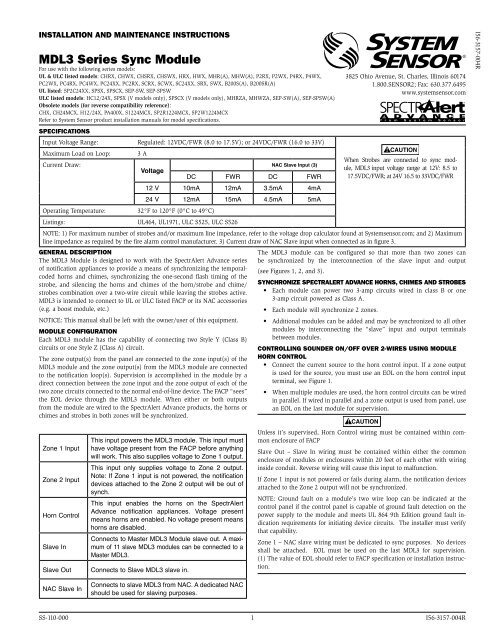
MDL3 Series Sync Module - System Sensor
MDL3 Series Sync Module - System Sensor
MDL3 Series Sync Module - System Sensor

Create successful ePaper yourself
Turn your PDF publications into a flip-book with our unique Google optimized e-Paper software.
inStaLLation anD Maintenance inStRUctionS<br />
<strong>MDL3</strong> <strong>Series</strong> <strong>Sync</strong> <strong>Module</strong><br />
For use with the following series models:<br />
UL & ULC listed models: CHRX, CHWX, CHSRX, CHSWX, HRX, HWX, MHR(A), MHW(A), P2RX, P2WX, P4RX, P4WX,<br />
PC2WX, PC4RX, PC4WX, PC24XX, PC2RX, SCRX, SCWX, SC24XX, SRX, SWX, B200S(A), B200SR(A)<br />
UL listed: SP2C24XX, SPSX, SPSCX, SEP-SW, SEP-SPSW<br />
ULC listed models: HC12/24X, SPSX (V models only), SPSCX (V models only), MHRZA, MHWZA, SEP-SW(A), SEP-SPSW(A)<br />
Obsolete models (for reverse compatibility reference):<br />
CHX, CH24MCX, H12/24X, PA400X, S1224MCX, SP2R1224MCX, SP2W1224MCX<br />
Refer to <strong>System</strong> <strong>Sensor</strong> product installation manuals for model specifications.<br />
3825 Ohio Avenue, St. Charles, Illinois 60174<br />
1.800.SENSOR2; Fax: 630.377.6495<br />
www.systemsensor.com<br />
SpecificationS<br />
Input Voltage Range: Regulated: 12VDC/FWR (8.0 to 17.5V); or 24VDC/FWR (16.0 to 33V)<br />
Maximum Load on Loop:<br />
Current Draw:<br />
3 A<br />
Voltage<br />
DC FWR<br />
NAC Slave Input (3)<br />
DC FWR<br />
CAUTION<br />
When Strobes are connected to sync module,<br />
<strong>MDL3</strong> input voltage range at 12V: 8.5 to<br />
17.5VDC/FWR; at 24V 16.5 to 33VDC/FWR<br />
12 V 10mA 12mA 3.5mA 4mA<br />
24 V 12mA 15mA 4.5mA 5mA<br />
Operating Temperature: 32°F to 120°F (0°C to 49°C)<br />
Listings: UL464, UL1971, ULC S525, ULC S526<br />
NOTE: 1) For maximum number of strobes and/or maximum line impedance, refer to the voltage drop calculator found at <strong>System</strong>sensor.com; and 2) Maximum<br />
line impedance as required by the fire alarm control manufacturer. 3) Current draw of NAC Slave input when connected as in figure 3.<br />
GeneRaL DeScRiption<br />
The <strong>MDL3</strong> module can be configured so that more than two zones can<br />
The <strong>MDL3</strong> <strong>Module</strong> is designed to work with the SpectrAlert Advance series be synchronized by the interconnection of the slave input and output<br />
of notification appliances to provide a means of synchronizing the temporalcoded<br />
horns and chimes, synchronizing the one-second flash timing of the<br />
strobe, and silencing the horns and chimes of the horn/strobe and chime/<br />
strobes combination over a two-wire circuit while leaving the strobes active.<br />
<strong>MDL3</strong> is intended to connect to UL or ULC listed FACP or its NAC accessories<br />
(see Figures 1, 2, and 3).<br />
<strong>Sync</strong>hRonize SpectRaLeRt aDvance hoRnS, chiMeS anD StRobeS<br />
• Each module can power two 3-amp circuits wired in class B or one<br />
3-amp circuit powered as Class A.<br />
(e.g. a boost module, etc.)<br />
• Each module will synchronize 2 zones.<br />
NOTICE: This manual shall be left with the owner/user of this equipment. • Additional modules can be added and may be synchronized to all other<br />
MoDULe confiGURation<br />
modules by interconnecting the “slave” input and output terminals<br />
Each <strong>MDL3</strong> module has the capability of connecting two Style Y (Class B) between modules.<br />
circuits or one Style Z (Class A) circuit.<br />
contRoLLinG SoUnDeR on/off oveR 2-WiReS USinG MoDULe<br />
The zone output(s) from the panel are connected to the zone input(s) of the hoRn contRoL<br />
<strong>MDL3</strong> module and the zone output(s) from the <strong>MDL3</strong> module are connected • Connect the current source to the horn control input. If a zone output<br />
to the notification loop(s). Supervision is accomplished in the module by a is used for the source, you must use an EOL on the horn control input<br />
direct connection between the zone input and the zone output of each of the terminal, see Figure 1.<br />
two zone circuits connected to the normal end-of-line device. The FACP “sees” • When multiple modules are used, the horn control circuits can be wired<br />
the EOL device through the <strong>MDL3</strong> module. When either or both outputs in parallel. If wired in parallel and a zone output is used from panel, use<br />
from the module are wired to the SpectrAlert Advance products, the horns or an EOL on the last module for supervision.<br />
chimes and strobes in both zones will be synchronized.<br />
CAUTION<br />
This input powers the <strong>MDL3</strong> module. This input must<br />
Unless it’s supervised, Horn Control wiring must be contained within common<br />
enclosure of FACP<br />
Zone 1 Input have voltage present from the FACP before anything<br />
will work. This also supplies voltage to Zone 1 output.<br />
Slave Out – Slave In wiring must be contained within either the common<br />
enclosure of modules or enclosures within 20 feet of each other with wiring<br />
This input only supplies voltage to Zone 2 output. inside conduit. Reverse wiring will cause this input to malfunction.<br />
Zone 2 Input<br />
Note: If Zone 1 input is not powered, the notification<br />
devices attached to the Zone 2 output will be out of<br />
synch.<br />
If Zone 1 input is not powered or fails during alarm, the notification devices<br />
attached to the Zone 2 output will not be synchronized.<br />
Horn Control<br />
This input enables the horns on the SpectrAlert<br />
Advance notification appliances. Voltage present<br />
means horns are enabled. No voltage present means<br />
horns are disabled.<br />
NOTE: Ground fault on a module’s two wire loop can be indicated at the<br />
control panel if the control panel is capable of ground fault detection on the<br />
power supply to the module and meets UL 864 9th Edition ground fault indication<br />
requirements for initiating device circuits. The installer must verify<br />
that capability.<br />
Slave In<br />
Connects to Master <strong>MDL3</strong> <strong>Module</strong> slave out. A maximum<br />
of 11 slave <strong>MDL3</strong> modules can be connected to a<br />
Master <strong>MDL3</strong>.<br />
Zone 1 – NAC slave wiring must be dedicated to sync purposes. No devices<br />
shall be attached. EOL must be used on the last <strong>MDL3</strong> for supervision.<br />
(1) The value of EOL should refer to FACP specification or installation instruc-<br />
Slave Out Connects to Slave <strong>MDL3</strong> slave in.<br />
tion.<br />
NAC Slave In<br />
Connects to slave <strong>MDL3</strong> from NAC. A dedicated NAC<br />
should be used for slaving purposes.<br />
SS-110-000 1 I56-3157-004R<br />
I56-3157-004R
fiGURe 1. hoRnS SiLenceD oveR tWo WiRe ciRcUit:<br />
NOTE: If zone 1 output of module is connected to strobes, chime/strobes or horn/<br />
strobes, zone 1 input supply power must be continuous for proper operation.<br />
FACP #1<br />
+<br />
+<br />
EOL<br />
HORN<br />
ZONE 1<br />
NAC 1} – (1) – CONTROL<br />
OUT<br />
+<br />
+<br />
ZONE 1 ZONE 2<br />
–<br />
– IN<br />
OUT<br />
+<br />
+<br />
ZONE 2<br />
NAC<br />
–<br />
– IN<br />
SLAVE IN<br />
B+<br />
B–<br />
NAC 2}<br />
B+<br />
B–<br />
NAC 3}<br />
B+<br />
MASTER MODULE HORN CONTROL CONNECTS TO INTERRUPTABLE POWER SOURCE<br />
TO NEXT<br />
SPECTRALERT<br />
ADVANCE DEVICE<br />
OR EOL (1)<br />
2 STYLE Y ZONES<br />
(CLASS B)<br />
MASTER<br />
TO NEXT<br />
SPECTRALERT<br />
ADVANCE DEVICE<br />
B–<br />
OR EOL (1)<br />
FACP #2<br />
B+ +<br />
NAC 1<br />
B– –<br />
}<br />
}<br />
A+ +<br />
A– –<br />
}<br />
}<br />
}<br />
}<br />
+<br />
SLAVE<br />
– IN<br />
}<br />
}<br />
}<br />
}<br />
+<br />
HORN<br />
– CONTROL<br />
+<br />
ZONE 1<br />
– IN<br />
+<br />
ZONE 2<br />
– IN<br />
+<br />
SLAVE<br />
– IN<br />
TEMP JUMP OFF<br />
SLAVE<br />
SLAVE<br />
OUT<br />
ZONE 1<br />
OUT<br />
ZONE 2<br />
OUT<br />
NAC<br />
SLAVE IN<br />
TEMP JUMP OFF<br />
SLAVE<br />
OUT<br />
}<br />
}<br />
}<br />
}<br />
}<br />
}<br />
}<br />
}<br />
+<br />
–<br />
fiGURe 3. MaSteR-SLave USinG nac-SLave inpUt:<br />
NOTE: If zone 1 is connected to synchronize other <strong>MDL3</strong> no devices shall be<br />
attached to this zone. Zone 1 input supply power must be continous to be<br />
operational.<br />
FACP<br />
B+ +<br />
NAC 1<br />
B– –<br />
B+ +<br />
NAC 2<br />
B– –<br />
}<br />
}<br />
FACP<br />
B+ +<br />
NAC 1<br />
B– –<br />
B+ +<br />
NAC 2<br />
B– –<br />
}<br />
}<br />
}<br />
}<br />
}<br />
}<br />
+<br />
HORN<br />
– CONTROL<br />
+<br />
ZONE 1<br />
– IN<br />
+<br />
ZONE 2<br />
– IN<br />
+<br />
SLAVE<br />
– IN<br />
}<br />
}<br />
}<br />
}<br />
+<br />
HORN<br />
– CONTROL<br />
+<br />
ZONE 1<br />
– IN<br />
+<br />
ZONE 2<br />
– IN<br />
+<br />
SLAVE<br />
– IN<br />
MASTER<br />
ZONE 1<br />
OUT<br />
ZONE 2<br />
OUT<br />
NAC<br />
SLAVE IN<br />
TEMP JUMP OFF<br />
ZONE 1<br />
OUT<br />
ZONE 2<br />
OUT<br />
NAC<br />
SLAVE IN<br />
TEMP JUMP OFF<br />
}<br />
}<br />
}<br />
}<br />
SLAVE<br />
OUT<br />
SLAVE<br />
}<br />
}<br />
}<br />
}<br />
SLAVE<br />
OUT<br />
fiGURe 4. WiRinG foR coDeD SUppLieS:<br />
MULTI CODE<br />
SOURCE<br />
MDL<br />
HC<br />
Z1<br />
IN OUT<br />
ANY<br />
SPECTRALERT<br />
HORN STROBE<br />
HORN<br />
POWER<br />
STROBE<br />
POWER<br />
+<br />
–<br />
+<br />
–<br />
+<br />
–<br />
+<br />
+<br />
–<br />
–<br />
+<br />
+<br />
–<br />
–<br />
+<br />
–<br />
+<br />
–<br />
+<br />
–<br />
+<br />
+<br />
–<br />
–<br />
+<br />
+<br />
–<br />
–<br />
+<br />
–<br />
WIRING MUST BE<br />
CONTAINED WITH EITHER<br />
THE COMMON ENCLOSURE<br />
OF MODULES OR<br />
ENCLOSURES WITHIN 20<br />
FEET OF EACH OTHER WITH<br />
WIRING INSIDE CONDUIT<br />
TO NEXT<br />
SPECTRALERT<br />
ADVANCE DEVICE<br />
TO NEXT<br />
SPECTRALERT<br />
ADVANCE DEVICE<br />
STYLE Z ZONES<br />
(CLASS A)<br />
A0414-01<br />
fiGURe 2 MaSteR-SLave MoDe:<br />
NOTE: If zone 1 output of module is connected to strobes, chime/strobes or horn/<br />
strobes, zone 1 input supply power must be continuous for proper operation.<br />
FACP<br />
B+ +<br />
NAC 1<br />
B– –<br />
B+ +<br />
NAC 2<br />
B– –<br />
(STYLE Z CLASS A)<br />
B+ +<br />
NAC 3<br />
B– –<br />
}<br />
}<br />
}<br />
}<br />
A+ +<br />
A– –<br />
}<br />
}<br />
}<br />
}<br />
+<br />
HORN<br />
– CONTROL<br />
+<br />
ZONE 1<br />
– IN<br />
+<br />
ZONE 2<br />
– IN<br />
+<br />
SLAVE<br />
– IN<br />
}<br />
}<br />
}<br />
}<br />
+<br />
HORN<br />
– CONTROL<br />
+<br />
ZONE 1<br />
– IN<br />
+<br />
ZONE 2<br />
– IN<br />
+<br />
SLAVE<br />
– IN<br />
MASTER<br />
ZONE 1<br />
OUT<br />
ZONE 2<br />
OUT<br />
NAC<br />
SLAVE IN<br />
TEMP JUMP OFF<br />
SLAVE<br />
SLAVE<br />
OUT<br />
ZONE 1<br />
OUT<br />
ZONE 2<br />
OUT<br />
NAC<br />
SLAVE IN<br />
TEMP JUMP OFF<br />
SLAVE<br />
OUT<br />
}<br />
}<br />
}<br />
}<br />
+<br />
–<br />
+<br />
–<br />
+<br />
–<br />
}<br />
}<br />
+<br />
–<br />
+<br />
–<br />
+<br />
–<br />
+<br />
–<br />
}<br />
}<br />
+<br />
–<br />
TO NEXT<br />
SPECTRALERT<br />
ADVANCE DEVICE<br />
OR EOL (1)<br />
2 STYLE Y ZONES<br />
(CLASS B)<br />
TO NEXT<br />
SPECTRALERT<br />
ADVANCE DEVICE<br />
OR EOL (1)<br />
WIRING MUST BE<br />
CONTAINED WITH EITHER<br />
THE COMMON ENCLOSURE<br />
OF MODULES OR<br />
ENCLOSURES WITHIN 20<br />
FEET OF EACH OTHER WITH<br />
WIRING INSIDE CONDUIT<br />
TO NEXT<br />
SPECTRALERT<br />
ADVANCE DEVICE<br />
TO NEXT<br />
SPECTRALERT<br />
ADVANCE DEVICE<br />
STYLE Z ZONES<br />
(CLASS A)<br />
A0415-01<br />
The sounder and/or strobe will not work without power. The sounder/strobe gets its power from the<br />
fire/security panel monitoring the alarm system. If power is cut off for any reason, the sounder/strobe<br />
will not provide the desired audio or visual warning.<br />
The sounder may not be heard. The loudness of the sounder meets (or exceeds) current Underwriters<br />
Laboratories’ standards. However, the sounder may not alert a sound sleeper or one who has recently<br />
used drugs or has been drinking alcoholic beverages. The sounder may not be heard if it is placed on<br />
a different floor from the person in hazard or if placed too far away to be heard over the ambient noise<br />
such as traffic, air conditioners, machinery or music appliances that may prevent alert persons from<br />
hearing the alarm. The sounder may not be heard by persons who are hearing impaired.<br />
The signal strobe may not be seen. The electronic visual warning signal uses an extremely reliable<br />
xenon flash tube. It flashes at least once every three seconds and exceeds current Underwriters<br />
Laboratories standards for private mode viewing. The visual warning signal is suitable for direct view-<br />
<strong>System</strong> <strong>Sensor</strong> warrants its enclosed product to be free from defects in materials and workmanship under<br />
normal use and service for a period of three years from date of manufacture. <strong>System</strong> <strong>Sensor</strong> makes<br />
no other express warranty for the enclosed product. No agent, representative, dealer, or employee of<br />
the Company has the authority to increase or alter the obligations or limitations of this Warranty. The<br />
Company’s obligation of this Warranty shall be limited to the replacement of any part of the product<br />
which is found to be defective in materials or workmanship under normal use and service during the<br />
three year period commencing with the date of manufacture. After phoning <strong>System</strong> <strong>Sensor</strong>’s toll free<br />
number 800-SENSOR2 (736-7672) for a Return Authorization number, send defective units postage prepaid<br />
to: <strong>System</strong> <strong>Sensor</strong>, Returns Department, RA #__________, 3825 Ohio Avenue, St. Charles, IL 60174.<br />
thRee-yeaR LiMiteD WaRRanty<br />
SPECTRALERT<br />
HORN ONLY<br />
TO NEXT<br />
SPECTRALERT<br />
ADVANCE DEVICE<br />
OR EOL (1)<br />
TO NEXT<br />
SPECTRALERT<br />
ADVANCE DEVICE<br />
OR EOL (1)<br />
TO NEXT <strong>MDL3</strong> NAC<br />
SLAVE IN OR EOL (1)<br />
2 STYLE Y ZONES<br />
(CLASS B)<br />
TO NEXT SPECTRALERT<br />
ADVANCE DEVICE OR EOL (1)<br />
TO NEXT<br />
HORN<br />
POWER<br />
OR<br />
EOL (1)<br />
} TO NEXT<br />
DEVICE<br />
OR EOL (1)<br />
}<br />
A0416-01<br />
NOTE: Horn control must be powered for horn/strobes to operate the horn portion.<br />
NOTE: SpectrAlert Advance horn-only/chime-only and horn/strobe or chime/<br />
strobe devices must be set to coded for multi-code sourcing.<br />
fiGUReS 5 & 6. MoUntinG DiaGRaM:<br />
BARRIER STRIPS<br />
1. Fold barrier strip flat and complete field wiring. Input terminal wire<br />
gauge: 12 to 18 AWG.<br />
2. Fold barrier strips toward terminal block and mount unit to back box with<br />
screws provided. Back box must be 4-11 /16˝ x 4-11 /16˝ x 2-1 /8˝ deep.<br />
Please refer to insert for the Limitations of Fire Alarm <strong>System</strong>s<br />
WARNING<br />
the LiMitationS of SoUnDeR/StRobeS<br />
A0265-01<br />
A0423-00<br />
ing and must be installed within an area where it can be seen by building occupants. The strobe must<br />
not be installed in direct sunlight or areas of high light intensity (over 60 foot candles) where the visual<br />
flash might be disregarded or not seen. The strobe may not be seen by the visually impaired and is not<br />
intended to meet American Disabilities Act (ADA) requirements.<br />
The signal strobe may cause seizures. Individuals who have positive photic response to visual stimuli<br />
with seizures, such as persons with epilepsy, should avoid prolonged exposure to environments in<br />
which strobe signals, including this strobe, are activated.<br />
The signal strobe cannot operate from coded power supplies. Coded power supplies produce interrupted<br />
power. The strobe must have an uninterrupted source of dc power in order to operate correctly. <strong>System</strong><br />
<strong>Sensor</strong> recommends that the sounder and signal strobe always be used in combination so that the risks<br />
from any of the above limitations are minimized.<br />
Please include a note describing the malfunction and suspected cause of failure. The Company shall not<br />
be obligated to replace units which are found to be defective because of damage, unreasonable use,<br />
modifications, or alterations occurring after the date of manufacture. In no case shall the Company be<br />
liable for any consequential or incidental damages for breach of this or any other Warranty, expressed<br />
or implied whatsoever, even if the loss or damage is caused by the Company’s negligence or fault. Some<br />
states do not allow the exclusion or limitation of incidental or consequential damages, so the above<br />
limitation or exclusion may not apply to you. This Warranty gives you specific legal rights, and you may<br />
also have other rights which vary from state to state.<br />
SS-110-000 2 I56-3157-004R<br />
©2012 <strong>System</strong> <strong>Sensor</strong>