R&S®ETL TV Analyzer - Product Brochure - Rohde & Schwarz
R&S®ETL TV Analyzer - Product Brochure - Rohde & Schwarz
R&S®ETL TV Analyzer - Product Brochure - Rohde & Schwarz

You also want an ePaper? Increase the reach of your titles
YUMPU automatically turns print PDFs into web optimized ePapers that Google loves.
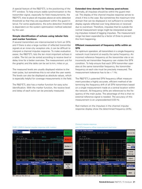
A special feature of the R&S®ETL is the positioning of theFFT window. To help ensure stable synchronization to thetransmitter signal, especially for field measurements, theR&S®ETL tries to place all impulses above an echo detectionthreshold so that they are equidistant within the guard interval.For some applications, the echo detection thresholdis dependent on the system optimization method selectedby the user.Simple identification of echoes using tabular listsand marker functionsIf several transmitters are interconnected to form an SFN,and if there is also a large number of reflected transmittersignals at an inner-city reception site, it can be difficult tointerpret a channel impulse response. To make evaluationeasier, the R&S®ETL lists the ten most important echoes ina table. The list can be sorted according to receive level ordelay time for a better overview. The measurement unit forthe graphic and the table can be set to km, miles or µs.The measured levels are usually displayed relative to themain pulse, but sometimes this is not what the user wants.The levels can also be displayed as absolute values, whichis especially helpful for coverage measurements in the field.The R&S®ETL also has a marker function for easy echoidentification. With the marker function, the receive leveland delay of each echo can be precisely measured.Extended time domain for faraway post-echoesNormally, all impulses should be within the guard interval.The display of the channel impulse response serves tocheck if this is the case. But sometimes the maximum timedomain that can be displayed is not sufficient to correctlydisplay signals reflected over long distances or receiveddue to overshoot. Therefore, impulses that lie outside thenormal measurement range might be interpreted as leadingimpulses instead of lagging impulses. The measurementrange has been expanded by a factor of three to preventthis from happening.Efficient measurement of frequency drifts within anSFNFor optimum operation, all transmitters in a single-frequencynetwork must transmit at exactly the same frequency. Anincorrect reference frequency at the transmitter site or anincorrectly set transmitter frequency can violate this SFNcondition. To help ensure that each SFN transmitter operatesat the same transmitter frequency, the transmitterfrequency at each site must be precisely measured. Themeasurement tolerance has to be < 1 Hz.The R&S®ETL's patented SFN frequency offset measurementprovides a highly accurate, efficient method of determiningthe frequency drift of all SFN transmitters basedon a single measurement made at a central location withinthe network. All frequency drifts are referenced to the frequencyof the main pulse. The advantage of this is that noexternal reference signal is needed. The accuracy of thismeasurement is an unprecedented 0.03 Hz.Red markers on the impulses in the channel impulseresponse display show the determined frequency drifts.DVB-T, DVB-H channel impulse response with markers.Channel impulse responsewith SFN frequency offset-measurement (red lines).<strong>Rohde</strong> & <strong>Schwarz</strong> R&S®ETL <strong>TV</strong> <strong>Analyzer</strong> 21