User Manual - VDSL - BlueView Technologies, Inc.
User Manual - VDSL - BlueView Technologies, Inc.
User Manual - VDSL - BlueView Technologies, Inc.

You also want an ePaper? Increase the reach of your titles
YUMPU automatically turns print PDFs into web optimized ePapers that Google loves.
P-Series with <strong>VDSL</strong>Sonar <strong>User</strong> HandbookPart Number: 203358-01Revision: BJan 2012©<strong>BlueView</strong> <strong>Technologies</strong>, <strong>Inc</strong>. All rights reserved.All product names are trademarks of their respective companies.
Table of ContentChapter 1 Welcome .................................................................. 4About the <strong>BlueView</strong> Sonar .......................................................................... 4Chapter 2 System Contents...................................................... 5Chapter 3 Understanding Imaging Sonar ................................. 6What is Imaging Sonar? ............................................................................. 6How do I interpret the Sonar images? .......................................................... 6Chapter 4 Sonar System Installation ....................................... 7Install Software on your PC......................................................................... 7Set your PC’s network card IP address ......................................................... 8Assemble System for Ethernet Connectivity .................................................. 9Required Cables: ....................................................................................... 9Assemble System for <strong>VDSL</strong> Connectivity ...................................................... 11Firewall Configuration ............................................................................... 12Chapter 5 Sonar Installation .................................................. 13Mount the Sonar ....................................................................................... 13Mounting Method ...................................................................................... 13Mounting Location .................................................................................... 13Sonar Up-Down Orientation ....................................................................... 13Sonar Angle ............................................................................................. 14Chapter 6 Sonar Operation .................................................... 16Connect to the Sonar ................................................................................ 16Dual Frequency Sonars ............................................................................. 16Image Calibration ..................................................................................... 17Shutdown ................................................................................................ 18Maintenance ............................................................................................ 18Chapter 7 Troubleshooting .................................................... 19If the ProViewer Software cannot see the sonar head: .................................. 19If the image updates seem slow: ................................................................ 21Appendix A: Technical Specifications ......................................... 22Appendix B: Mechanical Drawings ............................................. 23
Appendix C: Cable Diagrams ...................................................... 25
<strong>BlueView</strong> <strong>Technologies</strong> has made every effort to ensure the accuracy andcompleteness of this document; however, because ongoing development efforts aremade to continually improve the capabilities of our products, we cannot guarantee theaccuracy of the contents of this document. We disclaim liability for errors, omissions,or future changes herein.Copyright © 2003-2012 <strong>BlueView</strong> <strong>Technologies</strong> Corp. All rights reserved. No part ofthis publication may be copied, reproduced, or translated, without the prior writtenconsent of <strong>BlueView</strong> <strong>Technologies</strong>. No part of this publication may be stored ortransmitted in any electronic form without the prior consent of <strong>BlueView</strong> <strong>Technologies</strong>.Any unauthorized use is a violation of copyright laws.Warning! This device should not be used as a navigational aid to prevent collision,grounding, boat damage, or personal injury.Warning! This product contains lead, a chemical known to the state of California tocause cancer, birth defects and other reproductive harm. Handling and/or opening thisunit may result in exposure to lead, in the form of solder.Warning! Disassembly and repair of this electronic unit should only be performed byauthorized service personnel. Any modification of the serial number or attempt torepair the original equipment or accessories by unauthorized individuals will void thewarranty.Warning! Changes or modifications to this unit not expressly approved by the partyresponsible for compliance may void the user’s authority to operate this equipment.Warning! This equipment contains High Voltage electronics. Tampering with or usingdamaged equipment could lead to serious injury.Warranty Information:The sonar is backed by a standard 12-month parts and labor warranty policy.For more information on safety and/or maintenance issues please call <strong>BlueView</strong><strong>Technologies</strong> at 206.545.7260.3
Chapter 1WelcomeCongratulations on your purchase of a <strong>BlueView</strong> 2D Miniature MultibeamImaging Sonar system. This manual covers operations of the P-Series with <strong>VDSL</strong>sonar systems.<strong>BlueView</strong> 2D imaging sonar provides streaming sonar imagery, making it easyto search and navigate in low and zero visibility water. <strong>BlueView</strong> has coupled highperformanceimaging capability with a powerful software package creating one ofthe world’s most versatile underwater imaging systems available today.Advanced sonar technology, rugged design, and powerful software are just afew highlights of your sonar system. This manual explains imaging sonarinterpretation and provides instructions on the installation and operation of yoursonar system. For detailed information on using the sonar imaging software,please see the ProViewer Software Handbook found both on the software CD aswell as under the software’s help menu.About the <strong>BlueView</strong> SonarYour sonar is a general-purpose underwater imaging sonar designed for ROV,AUV, vessel mounted, and stationary tripod integration. With its dual Ethernet or<strong>VDSL</strong> interface and user-friendly software, the sonar system is designed to be justas easy-to-use as it is functional.4
Chapter 2System ContentsAll <strong>BlueView</strong> P-Series with <strong>VDSL</strong> sonar systems come with the sonar head andan accessory kit. The accessory kit includes the following:Power-Over-Ethernet (POE) Box with power cable<strong>VDSL</strong> Top Side Box with power cableSonar to Surface Cable (25 ft.) with <strong>VDSL</strong> and EthernetConnectorsCable Whip (4 ft.)<strong>VDSL</strong> Top Side Whip (RJ11 connector)Ethernet Cable (7 ft.)ProViewer CDQuickstart Guide<strong>User</strong> HandbookRugged Carry Case5
Chapter 3Understanding Imaging SonarWhat is Imaging Sonar?Many people are familiar with scanning type sonar, which employ mechanicalrotation of a single acoustic beam over an imaging area. This works well whenused on stationary platforms and/or when imaging static targets. They becomemuch less useful when working from a moving platform and/or trying to imagemoving targets since any motion can cause errors in the final image. Bycomparison, <strong>BlueView</strong> imaging sonar are multi-beam sensors, which form manysmall acoustic beams at once. This allows them to work well from stationary andmoving platforms. An imaging sonar can produce several high-quality images persecond, making it possible to get movie-like imagery from the sonar.How do I interpret the Sonar images?Imagine a flashlight lying on a table and an object such as a coffee cup locatedin front of the flashlight. If you look down on this scene, you will see a bright areawhere light is reflecting off the face of the coffee cup. You will also see a darkshadow behind the coffee cup where light is unable to reach. The same idea canbe applied to a <strong>BlueView</strong> imaging sonar by replacing the light source with a soundsource. Bright areas on the sonar image are the result of objects reflecting sound,while dark areas are acoustic shadows resulting from an object blocking thesound. The two figures below provide an example of how a given scene wouldappear when viewed visually and with high-definition imaging sonar:6
Chapter 4Sonar System InstallationThe following chapter contains step by step instructions for setting up your<strong>BlueView</strong> sonar. For more information on the specifics of operating the sonar, seethe ProViewer Software Handbook found both on the software CD as well as underthe software’s help menu for more information about your ProViewer Software.Install Software on your PCTo install ProViewer, just insert the ProViewer CD into your computer’s CD-ROMdrive. You may also launch the installation by double clicking on setup.exe in theCD’s root directory. Follow the instructions to complete the installation.If you have a personal firewall enabled you may receive a warning messagesaying that ProViewer is attempting to send information to the Internet. Thesemessages are caused by ProViewer looking for <strong>BlueView</strong> sonar on your network.<strong>BlueView</strong> recommends that you select the option that will always allow ProViewerto access the network. For example, in the image below, click Unblock.7
Set your PC’s network card IP addressIn Windows, open the ‘Control Panel’. In the control panel, open the ‘Networkconnections’ folder. In ‘Network connections’ folder, select the interface you’ll beattaching the sonar to. This interface is commonly called ‘Local Area Connection’,but might have another name in your particular application. In the ‘Local AreaConnection’ window, select ‘Properties’ In the ‘Properties’ window, select ‘InternetProtocol’ and click on the ‘Properties’ button. In the resultant ‘Internet Protocol(TCP/IP) Properties’ window, configure it as shown below:After you’ve set the IP address and Subnet mask as shown, close all thewindows you just opened.8
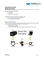
Assemble System for Ethernet ConnectivityAfter installing the PC software found on the included CD, the sonar system canbe connected for a bench-top test. The standard sonar package comes witheverything needed to get up and running quickly. The only additional itemrequired is an AC power source (your typical wall plug). The figure below depictshow the components are interconnected. Your sonar may look different than theone depicted below.Required Cables:AC Power Cable25ft Sonar to Surface Cable Standard Ethernet Cable9
The following are the recommended installation procedures for the Sonar system.1. Inspect all cable connector contacts for lack of moisture, corrosion, ordamage before assembling the system.2. Connect the underwater connector on the “25ft Sonar to Surface Test Cable”to the mating bulkhead connector on the rear of the sonar head. Make sure thatall o-rings are present and in good shape before making the connection. Onceconnected, ensure that the connector is fully engaged and tightened.3. Connect the RJ45 connector on the Sonar to Surface Test Cable to the“SONAR J1” port on the POE Box.4. Connect one end of the Standard Ethernet Cable to the “PC J2” port on thePOE Box.5. Connect the other end of the Standard Ethernet Cable to the Ethernet port onthe <strong>User</strong> computer.6. Plug the POE box power cable into a standard 120 VAC wall outlet. Thesonar head will power up and initialize itself in approximately 40 seconds.Note: When power cycling, correct operation requires that power be cycledfrom the AC side of the POE box. If you cycle the power off briefly, make sure youleave the power unplugged for at least 10 seconds.7. Turn on your computer.8. Start ProViewer, and click the “Connect” button.If ProViewer is able to connect to the sonar, the bench top test is successful. Ifnot, refer to Chapter 7, “Troubleshooting.”10
Assemble System for <strong>VDSL</strong> ConnectivityThe <strong>VDSL</strong> option enables communication over a single twisted pair. The figurebelow depicts how the components are interconnected. Your sonar and <strong>VDSL</strong> topside box may look different than the ones depicted below.<strong>VDSL</strong> Dip Switch Settings1 On2 Off3 On4 OffLEDs DefinitionOnce the converter connects to apower source, the LEDs of 10/100M willblink once, and the converter beginslooking for other converter automatically.During searching, the <strong>VDSL</strong> LEDs keepsblinking; it will stop blinking aftersuccessful detection.11
The following are the recommended installation procedures for the Sonar system.1. Inspect all cable connector contacts for lack of moisture, corrosion, ordamage before assembling the system.2. Connect the underwater connector on the “25ft Sonar to Surface Test Cable”to the mating bulkhead connector on the rear of the sonar head. Make sure thatall o-rings are present and in good shape before making the connection. Onceconnected, ensure that the connector is fully engaged and tightened.3. Connect the RJ11 connector on the Sonar to Surface Test Cable to the“<strong>VDSL</strong>” port on the <strong>VDSL</strong> Top Side box.4. Plug the power cable to the <strong>VDSL</strong> Top Side box to a standard wall outlet.5. Connect the RJ45 connector of the 25 ft cable to the “SONAR J1” port onthe POE Box.6. Connect one end of the Standard Ethernet Cable to the “LAN” port on the<strong>VDSL</strong> Top Side Box.7. Connect the other end of the Standard Ethernet Cable to the Ethernet port onthe <strong>User</strong> computer.8. Plug the POE box power cable and the <strong>VDSL</strong> power cable into a standard walloutlet. The sonar head will power up and initialize itself in approximately 60seconds.Note: When power cycling, correct operation requires that power be cycledfrom the AC side of the POE box. If you cycle the power off briefly, make sure youleave the power unplugged for at least 10 seconds.9. Turn on your computer.10. Start ProViewer, and click the “Connect” button.If ProViewer is able to connect to the sonar, the bench top test is successful. Ifnot, refer to Chapter 7, “Troubleshooting.”Firewall ConfigurationProViewer Software communicates with the sonar head using standardnetworking protocols. If your PC has firewall software, you may see a warning‘popup’ that asks permission to allow the ProViewer Software to connect to thesonar. In that case, you may need to configure your PC’s firewall to allowcommunications between your sonar and your PC using TCP and UDP on port1149. Refer to your anti-virus/firewall software vendor or your computer techsupport resources for assistance with your anti-virus/firewall software.12
Chapter 5Sonar InstallationMount the SonarAfter installing your software and running your sonar for the first time, you’reready to put the sonar into the water.Mounting MethodIn order to do this, the sonar needs a mounting structure to hold it securely inits underwater environment. This mount can either be one purchased from<strong>BlueView</strong>, or a customer supplied mount. The preferred mounting method is aclamp type fixture around the cylindrical portion of the unit. For custom mounts,refer to the technical drawings provided in the appendix of this manual for sonardimensions.Mounting LocationThe sonar images like a camera out of the front of the nose cone. It should bemounted looking forward, preferably on the same pan-and-tilt as the ROV’s maincamera.Sonar Up-Down OrientationUse the stickers and connector placement on the rear end cap, or the <strong>BlueView</strong>Logo on the front of the sonar to determine the up-down orientation of the sonar.TopTopBottomBottom13
Sonar AngleTo achieve optimal performance while imaging targets and/or the bottom at agiven depth, the angle that the sonar is tilted down from the surface is important.This issue is demonstrated in the figures below. On the left, the sonar is tilteddown at a steep angle that provides only a narrow field of view of the bottom. Thesonar on the right-hand figure is set at a much shallower angle that provides botha better perspective on targets and a larger field-of-view of the bottom.The sonar’s steep tilt-angle in this figureproduces imagery of a narrow strip of thebottom.The sonar’s shallow tilt-angle in this figureproduces an image of the bottom over abroad area. In general, shallower tilt-angles,which give larger areas of bottom imaging,are preferred.TargetDepth (ft)Approx.TiltAngle(Deg)0 10 20 30 40 60 800 3 8 10 10 15 2014
Wiring the Cable WhipLocate the cable wiring diagram in appendix C of this manual for the correcttype of connector on your sonar.Test the System Apply power to the system Start ProViewer software Once the sonar is fully powered up (approximately 45 seconds) click theconnect buttonPrecautions When power cycling the sonar, be sure to allow at least 10 seconds of ‘offtime’ before turning the sonar back on. If your network configuration requires a different sonar IP address than thefactory default, you can change it within the ProViewer application. If you decide todo that, you must change your PC’s IP address and net mask to compatible settings.Refer to the ProViewer software manual included in your ProViewer CD for moreinformation about sonar IP addressing.15
Chapter 6Sonar OperationConnect to the SonarOnce you’ve verified your computer is correctly configured and your hardwarecomponents are connected, start the ProViewer software and click the ‘connect’icon.ConnectThe ProViewer software should connect to the sonar head. If ProViewer cannotconnect to the sonar, see the trouble shooting section of this handbook.Dual Frequency SonarsSome <strong>BlueView</strong> products operate at more than one center frequency. Thosesonars are called ‘multi-head’ sonars. When connecting to a multi-head sonar, the‘Sonar Devices’ window will show you all the sonar heads available to connect to:Simply double-click the head you want to use, or select the head and click the‘connect’ button.16
If already connected to a sonar head, you can switch which head you are usingwith the ‘Head’ drop-down menu:Image CalibrationIf an image looks broken or misaligned, CTRL-J will bring up the ImageCalibration dialog.The top slider aligns the center of the image, and the bottom aligns the outeredges.17
ShutdownTo shutdown the sonar, close the “Sonar Window” by clicking on the “X” icon inthe top right-hand corner of the window, or select Exit from the File menu toclose the entire program. It is now safe to power down the sonar or disconnectthe Ethernet cable from the computer.MaintenanceTo ensure continued good operation of your sonar system, follow thesepractices:1. After use in salt water, rinse the sonar head and connectors off with freshwater, blow connector contacts clean and coat lightly with dielectric grease.2. Before use, ensure connector contacts are clear of dirt and corrosion andprotected with dielectric grease.18
Chapter 7TroubleshootingIf the ProViewer Software cannot see the sonar head:PossibleCauseNo PowerImproperlyconnectedBad StateDirtyconnectorsPossible SolutionConfirm that the ProViewer Junction (POE) Box is plugged into astandard 120VAC outlet and that the small green LED on the POEBox is glowing. Also check that the Sonar-to-Surface cable isplugged into the “SONAR J1” port on the POE Box.In addition to the connections described above, verify that youhave a good cable between the computer Ethernet port and the“PC J2” port on the POE Box.Reset the sonar by removing the POE box AC power cord for 10seconds. The sonar head takes 40 seconds to reboot after power isre-applied.Make sure that all connector pins are clean and corrosion free.The sonar head cabling is conveniently designed so that you canconnect your POE Box to a PC with a standard Ethernet cable.ImproperEthernet cablePCnetworkingsoftware isconfusedThe price for this convenience is paid when connecting your POEBox to a network hub. In this case, you will need to use a‘crossover’ Ethernet cable unless your network hardware iscapable automatically handling ‘crossed’ Ethernet cables.Sometimes the PC ‘arp’ table is corrupted and requires repair.There are several ways to do this, depending on your particular OS.On Windows you can: repair the arp table via the desktopnotification area icon:19
You can also simply restart the computer. Depending on yourparticular situation, it may also be helpful to cycle the power on thesonar. In this case, be sure to leave the sonar power disconnectedfor a full 10 seconds before restoring power.IP subnetmasks don’tmatchMake sure the subnet mask is the same on both PC and sonar.For the factory default ‘Class C network’ configuration, the subnetmask is 255.255.255.0. The ‘255’ part of the mask defines the‘network’ part of the IP address. The ‘0’ part of the mask definesthe ‘device’ part of the IP address.IP networkaddressesdon’t match.Make sure the IP *network* part of the IP address is the sameon both the sonar and the computer. In the factory default case,this is the first 3 numbers in the IP address: 192.168.1.IP networkdeviceaddresses arethe same.PoorconnectionqualityYou suspectyou’ve misconfiguredthe sonar IPaddressThe device part of the IP address must be *different* for everydevice on the network. In the factory default case, the sonar is setto 45 and the PC is set to 3. Don’t use 255, it’s reserved for‘broadcast’ use.Use an ohm meter to verify Tx and Rx line connectivity betweenthe Ethernet connector that plugs into the PC and the 10 pinconnector that plugs into the sonar head. Refer to “ProViewerSonar to Surface Cable Drawing” in the Appendix for pin to pinconnection information.To connect with the sonar, its IP address must be compatible withthe network or computer to which it is attached. If you misconfigurethe sonar’s network settings and are unable to connect toit, follow this procedure to reestablish communications with thesonar:1. Connect the sonar communication cable directly to aWindows XP computers network interface card. As described below in the ‘Running the sonar on a network’section, open the ‘Internet Protocol (TCP/IP) Propertieswindow for the network interface card you plugged thesonar into. Under the ‘General’ tab, select ‘Obtain an IP addressautomatically’. Under the ‘Alternate Configuration’ tab, select ‘Automaticprivate IP address’ and click OK.20
Close the rest of the Windows folders you opened. Cycle the sonar power off (for at least 10 seconds), thenturn the sonar back on. After about 100 seconds, the Widows PC and the sonarshould have negotiated ‘link local’ IP address (in the rangeof 169.254/16). Using the ProViewer software, ‘connect’ normally andreconfigure the sonar’s network settings to be compatiblewith its intended network.If the image updates seem slow:PossibleCauseEthernetcongestionRange settingsGUI window sizePossible SolutionShut down other computers or services that are consumingthe Ethernet network bandwidth. The sonar requires about10MBps of network bandwidth to operate.When your sonar ‘pings’, it has to wait for the echo toreturn from a distant object; long ‘range’ settings directlycause slow updates. Reduce the ‘Range Stop’ distance toincrease the update rate.The larger the displayed sonar image is, the longer it takesfor the ProViewer software to construct the image. Toincrease the image display update rate, decrease the size ofthe sonar image display window by grabbing one of sides orcorner of the GUI and dragging it towards the center of theGUI window.Still not working?Please contact us:<strong>BlueView</strong> <strong>Technologies</strong> Customer Supportwww.blueviewtech.com206-545-72608am – 5pm PST Mon through Fri21
Appendix A: Technical SpecificationsP900-45-P900-P900-P450-P450-<strong>VDSL</strong>90-<strong>VDSL</strong>130-<strong>VDSL</strong>90-<strong>VDSL</strong>130-<strong>VDSL</strong>SonarField-of-View 45º 90º 130º 90º 130ºMax. Range100m(328 ft.)100m(328 ft.)100m(328 ft.)250m(820 ft.)250m(820 ft.)Beam Width 1º x 20º 1º x 20º 1º x 20º 1º x 15º 1º x 15ºNumber ofBeams256 512 768 512 768Beam Spacing 0.18º 0.18º 0.18º 0.18º 0.18ºRangeResolution1 in. 1 in. 1 in. 2 in. 2 in.Update RateUp To15 HzUp To15 HzUp To15 HzUp To15 HzUp To15 HzFrequency 900 kHz 900 kHz 900 kHz 450 kHz 450 kHzMechanicalWeight in Air 6.0 lb 6.0 lb 6.0 lb 9.0 lb 9.0 lbWeight inWater1.9 lb 1.9 lb 1.9 lb 3.0 lb 3.0 lbDepth Rating 1,000m 1,000m 1,000m 1,000m 1,000mSize*12.3 in.12.3 in.12.3 in.14.4 in.14.4 in.x 5 in.x 5 in.x 5 in.x 7.1 in.x 7.1 in.*See Outline Drawings for exact dimensions.22
Appendix B: Mechanical DrawingsP900-<strong>VDSL</strong> Outline Drawing (Burton Connector Shown)23
P450-90-<strong>VDSL</strong> & P450-130-<strong>VDSL</strong> Outline Drawing(Burton Connector Shown)24
Appendix C: Cable DiagramsTABLE 1- BURTON INTERCONNECTIONTABLESIGNAL CONNECTOR CONDUCTORCOLORRx+ 1 ORG/WHTRx- 2 ORGTx+ 3 GRN/WHT12-48V 4RED (20 AWG)WHT (20 AWG)<strong>VDSL</strong> A 5 BRNTx- 6 GRNGROUND 7BLK (20 AWG)GRN (20 AWG)<strong>VDSL</strong> B 8 BRN/WHTTABLE 2- MKS INTERCONNECTIONTABLESIGNAL CONNECTOR CONDUCTORCOLORRx+ 1 ORG/WHTRx- 2 ORGTx+ 3 GRN/WHT12-48V 4 RED (20 AWG)12-48V 5 WHT (20 AWG)Tx- 6 GRNGROUND 7 BLK (20 AWG)GROUND 8 GRN (20 AWG)<strong>VDSL</strong> A 9 BRN<strong>VDSL</strong> B 10 BRN/WHT25
Integrate Sonar through ROV SystemFigure shows typical sonar/ROV integration into ROV system using a single twisted pair.Integration using a Single Twisted Pair (Burton Shown)26
Figure shows typical sonar/ROV integration into a fiber based ROV system.Integration using a Fiber to Ethernet Converter (Burton Shown)27