ProScan Software Handbook - BlueView Technologies, Inc.
ProScan Software Handbook - BlueView Technologies, Inc.
ProScan Software Handbook - BlueView Technologies, Inc.

Create successful ePaper yourself
Turn your PDF publications into a flip-book with our unique Google optimized e-Paper software.
<strong>ProScan</strong> <strong>Software</strong> <strong>Handbook</strong>Part Number: 202667-01Revision: B, August, 2011©<strong>BlueView</strong> <strong>Technologies</strong>, <strong>Inc</strong>. All rights reserved.All product names are trademarks of their respective companies.
Table of ContentsChapter 1: Welcome ................................................................................................... 6Overview ................................................................................................................ 6System Recommendations ........................................................................................ 6Technical Support .................................................................................................... 6Licensing Agreement ................................................................................................ 6Chapter 2: Connecting to the BV5000 ........................................................................... 7Installing <strong>Software</strong> .................................................................................................. 7Installing Hardware Drivers ...................................................................................... 8Configuring the Network ........................................................................................... 8Win XP ................................................................................................................ 8Windows Vista/7 ................................................................................................... 8Assembling the BV5000 System ................................................................................ 9Connecting BV5000 System to a Computer ............................................................... 10Connecting to a Pan & Tilt ...................................................................................... 10Bench Test the BV5000 .......................................................................................... 11Configure <strong>ProScan</strong> ................................................................................................. 11Chapter 3: Configuring the BV5000 ............................................................................ 12Range Threshold Level Controls ............................................................................... 12Sound Velocity ...................................................................................................... 12Override recorded Sound Velocity ............................................................................ 12BV5000 Orientation ............................................................................................... 13Pan / Tilt .............................................................................................................. 13Setup ................................................................................................................ 13Add Tilt Offset .................................................................................................... 13Beams Inverted .................................................................................................. 13Home Position ....................................................................................................... 14Chapter 4: Performing a BV5000 Scan ........................................................................ 15Running Single Scans ............................................................................................. 15Running Spherical Scans ........................................................................................ 16Scan Speed .......................................................................................................... 16File Name ............................................................................................................. 17File Types Created ................................................................................................. 17Heading, Pitch, and Roll ......................................................................................... 17©<strong>BlueView</strong> <strong>Technologies</strong> Page | 2
Depth .................................................................................................................. 18Latitude and Longitude ........................................................................................... 18Comments ............................................................................................................ 19Chapter 5: Reprocessing Data.................................................................................... 20Configure Recording .............................................................................................. 20Playing back a Scan ............................................................................................... 203D Point Cloud Files ............................................................................................... 22Chapter 6: <strong>ProScan</strong> Interface ..................................................................................... 23Toolbar ................................................................................................................ 23Opening a File .................................................................................................... 23Connecting to a Sonar ......................................................................................... 23Network Transmit ............................................................................................... 24New File ............................................................................................................ 24Image Calibration ............................................................................................... 24Length Measurement........................................................................................... 24Cursor Location .................................................................................................. 24Pan / Tilt Controls .................................................................................................. 25Pan Left ............................................................................................................. 25Pan Right ........................................................................................................... 25Tilt Up ............................................................................................................... 25Tilt Down ........................................................................................................... 25Communication Status ........................................................................................ 26Home Button ...................................................................................................... 26Start Button ....................................................................................................... 26Range Controls ..................................................................................................... 26Playback Controls .................................................................................................. 26Image Calibration .................................................................................................. 26Glossary of Terms .................................................................................................... 27Appendix A: Troubleshooting ..................................................................................... 28Connectivity Problems ............................................................................................ 28Rerun <strong>ProScan</strong> <strong>Software</strong> ......................................................................................... 28Reboot PC and Sonar ............................................................................................. 28Check Connectors .................................................................................................. 28Check Power ......................................................................................................... 29©<strong>BlueView</strong> <strong>Technologies</strong> Page | 3
Chapter 1: WelcomeOverviewThis manual describes the features and operational instructions for <strong>BlueView</strong> <strong>Technologies</strong>‟<strong>ProScan</strong> software. <strong>ProScan</strong> serves as graphical user interface for <strong>BlueView</strong>'s BV5000 andMicroBathymetry systems. <strong>ProScan</strong> can display, record, and stream live data from the sonaras well as open files for post processing or save data from rotational scans as 3D point cloudfiles. Finally, <strong>ProScan</strong> can communicate with third party bathymetry / line scanner softwarepackages.System RecommendationsFor best performance, <strong>ProScan</strong> requires a system that meets or exceeds the followingrequirements for optimum performance.‣ Windows XP/Vista/7 operating system‣ Dual-Core 1.8 GHz or faster processor‣ 2GB or more of RAM‣ 10GB or more of free disk space‣ CD-ROM drive for installation‣ 1 100Mbit or higher Ethernet interface‣ 2 USB PortsTechnical SupportAlthough we have attempted to make this manual as complete as possible, we realize thatthere are always additional unanswered questions, as well as unique situations not coveredby this document. <strong>BlueView</strong> is committed to providing industry leading customer service andtechnical support for all of our products. For technical assistance with <strong>ProScan</strong> or your<strong>BlueView</strong> sonar please email your questions to support@blueview.com, or contact ourcustomer service department at 206-545-7260 between the hours of 8am and 5pm PacificTime.For the latest contact information, data sheets and other support material please visit ourweb site at:Licensing Agreementhttp://www.blueview.comThe accompanying <strong>Software</strong> and Documentation hereinafter referred to as ”<strong>ProScan</strong>” areproprietary products owned by <strong>BlueView</strong> <strong>Technologies</strong>, <strong>Inc</strong>., and protected under U.S. andinternational copyright law. Except as authorized under this License Agreement, the<strong>Software</strong> may be used only on computers owned, leased, or otherwise controlled by you.You may not reverse assemble, reverse compile, or otherwise translate <strong>ProScan</strong>.©<strong>BlueView</strong> <strong>Technologies</strong> Page | 6
Chapter 2: Connecting to the BV5000There are several steps that need to be taken in order to use the BV5000 System.1. Installing the <strong>Software</strong>2. Installing Hardware Drivers3. Configuring the Network4. Assembling the Pan/Tilt device5. Connecting to the BV5000 system to a computer6. Bench test the BV50007. Configure <strong>ProScan</strong>Installing <strong>Software</strong>To install <strong>ProScan</strong>, insert the <strong>ProScan</strong> CD into your computer‟s CD-ROM drive. The installershould automatically run. If it does not, you may also launch the installation by doubleclicking on setup.exe in the CD‟s root directory. Follow the instructions to complete theinstallation.NOTE: We recommend that the software is installed and run with Administrator rights.If you have a personal firewall enabled you may receive a warning message saying that<strong>ProScan</strong> is attempting to send information to the Internet. These messages are caused by<strong>ProScan</strong> looking for <strong>BlueView</strong> sonar on your network. <strong>BlueView</strong> recommends that you selectthe option that will always allow <strong>ProScan</strong> to access the network. For example, in the imagebelow, click Unblock.Press UnblockFigure 1©<strong>BlueView</strong> <strong>Technologies</strong> Page | 7
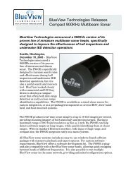
Figure 2Assembling the BV5000 SystemAttach the sonar to the sonar clamp by loosening the four cap screws, sliding the sonar in,and retightening the four cap screws. Use the locator pin, stickers, and side indicators todetermine the up/down orientation of the sonar. Figure 3, below, is the standard “VerticalUpright” “90 degree” orientation.Figure 3©<strong>BlueView</strong> <strong>Technologies</strong> Page | 9
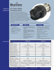
Connecting BV5000 System to a ComputerFollowing the diagram below:‣ Attach the sonar connector to the port on the end of the sonar.‣ Attach the pan/tilt connector to the port on the pan/tilt device.‣ Attach the other end of the cable to the SPT Junction box.‣ Connect the Ethernet cable from the SPT Junction box to the computer's Ethernetport.‣ Connect the USB cable from the SPT Junction box to the computer.Figure 4Connecting to a Pan & TiltIf the Auto-Connect to Pan/Tilt checkbox is checked, then <strong>ProScan</strong> will automatically detectand connect to an attached Pan/Tilt whenever a sonar connection is made.To manually connect to a pan/tilt, choose Connect to pan/tilt in the file menu.When <strong>ProScan</strong> has successfully connected to the pan/tilt, the Pan/Tilt control panel will bedisplayed.©<strong>BlueView</strong> <strong>Technologies</strong> Page | 10
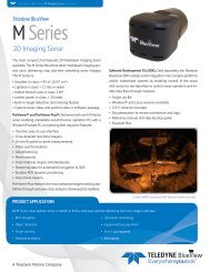
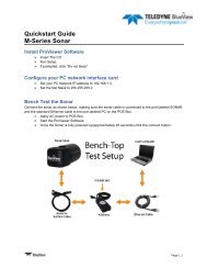
Bench Test the BV5000‣ Apply AC power to the SPT Junction Box and wait one minute.‣ IMPORTANT: Wait at least one minute for the network connection between theBV5000 and your computer to be established. The network may connect anddisconnect during this time, but do not attempt to use the BV5000 with <strong>ProScan</strong>until the network has stabilized.‣ Open the <strong>ProScan</strong> <strong>Software</strong> and click on the connect button:Figure 5‣ When the connect button is pressed, <strong>ProScan</strong> should connect automatically to thesonar.‣ If there is more than one sonar visible on the network, the Sonar Devices dialogbox will be displayedFigure 6‣ Select the desired Sonar/Head and click the Connect button. If the sonar doesnot connect, refer to the troubleshooting section of this manual on page 29.Configure <strong>ProScan</strong>‣ In <strong>ProScan</strong>, click File Settings and enter the appropriate sound speed.‣ Click the Recording tab. Click “Browse” and select a location to for data to bestored.©<strong>BlueView</strong> <strong>Technologies</strong> Page | 11
Chapter 3: Configuring the BV5000The Sonar Control window is accessible by clicking File Settings Sonar Controls.Figure 7Range Threshold Level ControlsThe Range Threshold specifies the intensity value above which a target will be recognized.The allowed values range from 100 to 20,000. The default value is 250, and values typicallyrange from 100 to 500.Sound VelocityThis is the sound velocity (in meters per second) used to compute target ranges and angles.Override recorded Sound VelocityWhen playing back a .SON file, you may wish to replace the recorded Sound Velocity with adifferent value. Click this box to do so.©<strong>BlueView</strong> <strong>Technologies</strong> Page | 12
BV5000 OrientationDefaults to Upright. Click the Inverted radio button if the BV5000 system is oriented asshown in the image on the right in Figure 7.Pan / TiltThe Pan/Tilt setup dialog is accessible through <strong>ProScan</strong>‟s settings (by clicking File Settings Pan/Tilt).SetupIf the Auto-Connect to Pan/Tilt checkbox is checked, then <strong>ProScan</strong> will automatically detectand connect to an attached Pan/Tilt whenever a sonar connection is made.Figure 8Add Tilt OffsetWhen checked, this allows the user to add an offset to tilt values that are used to processthe sonar data. This value can be either positive or negative decimal values.Beams InvertedWhen checked, this lets <strong>ProScan</strong> know that the sonar head itself is inverted in an otherwisenormal setup, i.e., the sonar is mounted upside down in an upright mount. This usuallyrequires bypassing the locator pin. When desired, this configuration should be used withcaution as this will cause erroneous output of the point cloud files.©<strong>BlueView</strong> <strong>Technologies</strong> Page | 13
Home PositionThe home position serves as the resting position for both pan and tilt axes. This is also the0, 0 position that all external offset measurements should be made from. Set the homeposition here, and click OK. This dialog’s degrees are specified in the pan/tilt manufacturer’scoordinate system, which uses 180 degrees at the center, and spans 0 to 360 degrees.<strong>BlueView</strong>‟s coordinate system used with the rest of <strong>ProScan</strong> is zero at the center, and spansfrom -180 to +180 degrees.Figure 9, Pan/Tilt Manufacturer's Coordinates©<strong>BlueView</strong> <strong>Technologies</strong> Page | 14
Chapter 4: Performing a BV5000 ScanScans are performed by clicking File Start Scan or the Start Scan button on the Pan/Tiltcontrol panel. Both Single Scans and Spherical Scans can be performed.Running Single ScansA single scan is a scan around a given total pan angle, maintaining one constant given tiltangle.To run a single scan, first move the sonar to the desired tilt angle, then check the SingleScan box, set the desired Scan Speed and Total Pan Angle, and click Start Scan. A progresswindow will appear while the scan is running.By default, the scan is centered about the Home position. If you want the scan centered atthe current pan position, check the “Center Scan(s) at current pan angle” checkbox. Notethat if the selected Total Pan Angle will hit a pan angle limit (less than -180, greater than180), then the start and stop angles will be adjusted so that the total scan angle is stillobtained. That is, if this option is checked when the current pan angle is -180, and a 360degree total scan angle is also selected, the scan will not be centered at -180, but will scan360 degrees from -180 to 180 degrees.©<strong>BlueView</strong> <strong>Technologies</strong> Page | 15
Running Spherical ScansSpherical scans allow a volume to be scanned in a single operation, by automaticallyconducting several single scans at different given tilt angles.Checking the Save Individual Scan Files box will preserve the files generated for each of theindividual scans after they are merged as described below. If not checked, the individualfiles will be deleted after merging is complete. If you want to view the 3D point cloud foreach of the individual scans, check the “run Meshlab after each scan” box.To run a spherical scan, check the Spherical Scan box, set the desired Scan Speed and TotalPan Angle. Different tilt angles will be displayed based on the sonar connected. Selectingany amount or all of them will cause the scans to progress at the tilt angles selected in theorder presented. A progress window will appear while the scan is running.A .SON file is output for each of the individual scans in a Spherical Scan. When the SphericalScan is completed, the individual files will be combined into a single .SON file. Thecombined file will have the name entered in the "Merge File Name" field with a suffix of"_complete" automatically appended. If no filename was entered in the field, then thename of the first scan will be used. The individual .SON files and 3D Point Cloud files willalso be renamed with that name, but with their tilt angle appended.NOTE: When performing a single scan, the tilt angle will remain constant at whatevertilt angle the system is set to when "Start Scan" is pressed.Scan SpeedScan speed can be designated in increments of 0.5 degrees per second, from 0.5 to 10.0degrees per second.The scan speed should be selected based on what type of scans are being taken and whatthe outputted data will be used for.©<strong>BlueView</strong> <strong>Technologies</strong> Page | 16
‣ For metrology and high density data purposes, it is highly recommendedto use only the 0.5 deg/sec and 1 deg/sec speed options. This will ensurethe highest data fidelity and accuracy.‣ If the scans are being taken as a quick check or for simple imaging purposes, thenhigher speeds may be used as long as the user realizes that there may be someloss of point location accuracy in the corresponding .XYZ and .OFF files.File NameAll scan files are saved in their own subdirectory that is generated based on the file namebase specified. Files can be named with some flexibility. Names can automatically begenerated by not selecting or inputting anything and the current date and time of the scanwill be used. If you wish to specify a special naming prefix, either enter it in the text field orclick the browse button and enter the location to use as the naming base.(This essentiallymanually creates the subdirectory ).One may also have an automatically incrementing index appended to the current file nameprefix, i.e. sampleFile1.son. This number will continue to increase until a different base filename is used or the program is exited.File Types CreatedSeveral file types are created when running scans:‣ .SON - This file contains the actual scan data.‣ .XYZ - This file contains point-cloud data where each point is described as:‣ .OFF - This file contains point-cloud data where each point is described as:‣ .TXT - This file contains information about the scan.Heading, Pitch, and RollHeading, pitch, and roll may be obtained with a Motion Reference Unit (MRU). The MRUmust be aligned with the sonar in the following way:1. Using the Pan/Tilt Home Position dialog, set the Pan and Tilt positions to 180.2. Using the Pan/Tilt Controls, move the sonar to the Home Position.3. Align the MRU's heading axis with the sonar axis.4. Verify that manually pitching the sonar (not with the pan/tilt) so that it points upcauses the MRU to output a positive pitch value.5. Verify that manually rolling the sonar so that its port side is up causes the MRU tooutput a positive roll value©<strong>BlueView</strong> <strong>Technologies</strong> Page | 17
NOTE: The Positive Y axis is the center of the Pan/Tilt, and indicates the direction thesonar is facing. The positive Z axis always points to the surface.Once aligned as described above, the MRU‟s heading (0 – 360 degrees), pitch (+/-degrees), and roll (+/- degrees) can be entered into the corresponding field in the ScanSetup dialog. When these values are entered, the orientation of the created 3D Point Cloudfiles is modified. When both pitch and roll data are known, the Z axis is oriented such that itis collinear with the local gravity vector. When heading is known, the Y axis in the pointcloud points to magnetic north. No local magnetic disturbance or declination is accountedfor unless the MRU is properly configured.DepthDepth should be measured to the tilt rotator‟s axis and entered as a positive number.Latitude and LongitudeLatitude and Longitude of the sonar should be entered if available.©<strong>BlueView</strong> <strong>Technologies</strong> Page | 18
CommentsEnter any comments describing the scan.The heading, pitch, roll, and depth inputs are applied to the X,Y, and Z values of each pointin the 3D Point Cloud. The heading, pitch, roll, and depth values are saved in the .SON file.The heading, pitch, roll, and depth values are also written out as comments (line starts witha “#” character) in the .XYZ and .OFF files.The Latitude and Longitude inputs are not applied to the X,Y, and Z values. They arerecorded to the .SON file and written out as comments to the .XYZ and .OFF files.The Comments input is recorded to the .SON file and written out as a comment to a .TXTfile alongside each generated .XYZ file.©<strong>BlueView</strong> <strong>Technologies</strong> Page | 19
Chapter 5: Reprocessing Data<strong>ProScan</strong> offers the ability to log the raw data before any filtering or threshold routines areperformed, making it convenient to post-process and/or reprocess data for improvedresults. Some of the controls one might alter to improve results are the threshold levelvalue and range windowing.When file recording is enabled, <strong>ProScan</strong> logs raw data to a file whenever the networktransmit function is enabled (when the “Network Transmit” function is pressed on the fronttoolbar, or a rotational scan is performed using an attached pan/tilt). The file name isautomatically generated based on the date and time when recording began. The formatused is "Day_MM_DD_HH_MM_SS_YYYY_TILTANGLE.son", where Y is the year, M themonth, D the day of the month, H the hour, M the minute, and S the seconds. TILTANGLEis optional and corresponds to the angle of the pan/tilt at the time of a scan. The fileextension is ".son".The pan/tilt position is stored for each ping in the SON file.To split recorded data over more than one file, press the New File button whilebroadcasting.Configure RecordingClick File Settings Recording to bring up the File Recording Setup dialog. To enable ordisable data logging, check or uncheck “File Recording Enabled,” and press OK. To changewhere files are saved type in a new location here or click “browse” to select one.Playing back a ScanRecorded single or spherical scans can be played back with different settings to transmitnetwork data or generate new 3D Point Cloud files after opening a .SON file. Clicking theScan... button on the Playback Controls will display the Playback Scan Setup dialog.©<strong>BlueView</strong> <strong>Technologies</strong> Page | 20
‣ Check the Generate 3D Point Cloud files box to re-create the XYZ and OFF files.To avoid over-writing the original 3D Point Cloud files, provide a new file name.‣ Check the Generate Network Output box to transmit network data.‣ Checking the Playback subset of file limits playback to the subset of the filespecified by the start and end ping numbers.‣ Check the "Override recorded values" to override values to the played back data,ignoring any values that may be saved in the file.‣ BV5000 Orientation: This box can be checked when processing a file to fix createpoint clouds with the specified orientation. This can be useful if the correctorientation was not used when initially collecting the data.‣ Checking the Add Tilt Offset box and entering a value in the box will add a tiltoffset to collected tilt values. This value should be a decimal value and can eitherbe positive or negative.‣ Checking the Lat/Long box will override/set the latitude and longitude values withthose specified in the boxes.‣ Checking the Comments box will override the comments included in the file.©<strong>BlueView</strong> <strong>Technologies</strong> Page | 21
3D Point Cloud FilesAs described above, .SON files are automatically created during scans. 3D Point Cloud filesare also created automatically, with the same names as the .SON file. Two kinds of 3D PointCloud files are created: XYZ files, with the extension “.xyz”, and OFF files, with theextension “.off”. In addition, a file with the extension ".txt" is also created.The .txt file contains descriptive information regarding the scan such as date, time, andprocessing parameters.Both kinds of 3D Point Cloud files are in ASCII format and represent 3D points using X, Y,and Z coordinates. The X and Y values are in meters from the sonar and are laid out on aCartesian grid with the sonar at the origin (X = 0, Y = 0). The Z values that are higher(shallower) than the sonar have positive values, and Z values lower (deeper) than the sonarhave negative values. If a depth value is provided as described in the on page 21, then Zvalues deeper than the water surface have negative values, effectively moving the origin tothe surface.XYZ files contain only four values on each line, separated by spaces. The first three valuesare the X, Y, and Z coordinates, and the fourth value is intensity.OFF files have a two-line header, followed by a line for each 3D point. Each of these lineshas the X, Y, and Z, followed by the color assigned to that point, expressed as RGBA. Eachof the X, Y, Z, and RGBA values are separated by spaces. .OFF files do not contain intensityvalues.The color map used assigns blue to the deepest points and red to the shallowest points.Meshlab and other 3D viewers use this color map to display the points.©<strong>BlueView</strong> <strong>Technologies</strong> Page | 22
Chapter 6: <strong>ProScan</strong> InterfaceToolbarRangeControlsPan & TiltControlsSonar ImageDisplayPlaybackControlsPlayback Time SliderCursor Location ReadoutToolbarThe toolbar provides quick access to several commonly used sonar functions.Opening a FileThis allows the user to select a sonar file (.son) to open. Both playback and network outputwill begin automatically.Connecting to a SonarTo connect to a sonar, simply click the connect icon on the toolbar. This will connect to thesonar at the network address specified in the Sonar Connection dialog.©<strong>BlueView</strong> <strong>Technologies</strong> Page | 23
Network TransmitIf <strong>ProScan</strong> is connected to both a sonar and a network, click the transmit button to beginstreaming data to the network. See the section on network configuration section later in thismanual for more information. If the UPD protocol is configured, data begins transmittingautomatically. If the TCP protocol is configured, <strong>ProScan</strong> waits for a TCP client to connect.New FileIf recording is enabled, <strong>ProScan</strong> records all broadcasting data to an automatically generated.SON file. To split recorded data between files, click the new file button while <strong>ProScan</strong> is setto record. A new .SON file will be created, and the remainder of the data will be storedthere.NOTE: Data files are automatically stored in C:\Documents and Settings\Username\.This can be changed in the Recording Setup dialog.Image CalibrationThis will display a dialog that will allow the user to adjust the sound speed to be used. Thisvalue will also be saved in the settings dialog. See the Image Calibration section later in thischapter for more information.Length MeasurementAfter clicking the length measurement icon in the toolbar, click the location where you wantto start the measurement. <strong>ProScan</strong> then draws a dotted line between that point and themouse cursor. Click a second time to freeze the current measurement. A third click sets thestarting point for a new measurement.The length of the dotted line is displayed just to the left of the cursor location in the lowerright of the <strong>ProScan</strong> window. To clear the measurement line, press the Measurementbutton a second time or right-click the mouse.Cursor LocationThe current range (meters) and bearing (degrees) of the cursor is displayed in the lowerright corner of the <strong>ProScan</strong> window.©<strong>BlueView</strong> <strong>Technologies</strong> Page | 24
Pan / Tilt Controls<strong>ProScan</strong> displays the sonar position control on the right side of the screen.The status of the communication link with the Pan/Tilt is shown in a color-coded display. Agreen display indicates a good link. A red display indicates that the link has failed andcommunications with the Pan/Tilt have been lost. A display that alternates between greenand red indicates a link with intermittent faults. The cabling and connections between thePC and the Pan/Tilt should be inspected for faults if any red is displayed. Scans should notbe performed if any red is displayed as the Pan/Tilt position data will be degraded orincorrect.Use the directional buttons to move the pan/tilt.Figure 10Pan LeftWhen a pan/tilt device is connected, this allows the user to pan the sonar counterclockwise,as viewed from above the BV5000.Pan RightWhen a pan/tilt device is connected, this allows the user to pan the sonar clockwise, asviewed from above the BV5000.Tilt UpWhen a pan/tilt device is connected, this allows the user to tilt towards the surface.Tilt DownWhen a pan/tilt device is connected, this allows the user to tilt towards the bottom.©<strong>BlueView</strong> <strong>Technologies</strong> Page | 25
Communication StatusWhen a pan/tilt device is connected, this indicates whether the pan/tilt device iscommunicating. The box should be green. It will only be red when the pan/tilt data iscorrupt, or not flowing.Home ButtonWhen a pan/tilt device is connected, this button allows the user to command the device togo to its home location. The Home position is defined as the center rotation angle for eachaxis.Start ButtonWhen a BV5000 system is connected, this allows the user to open a dialog to setup andstart a scan. This button will not appear if the pan/tilt is malfunctioning.Range ControlsThe Stop Range slider allows you to change the sonar's stop range (measured in meters).The stop range specifies how far out the sonar is looking. The Start Range slider specifiesthe range at which the system starts processing line data. Line data is processed from thisStart range to the Stop range. Sonar data is always displayed starting from the minimumrange of the sonar.Playback ControlsWhen a file is loaded, the playback controls appear at the bottom of the window. The tablebelow describes the different controls available. Also available between the previous pingand next ping buttons is the time slider. It shows the current location inside the file. Youmay click on it to jump to a new location or simply drag the marker back and forth toquickly scan through a file.Function Icon DescriptionPausePlayPrevious PingNext PingPause playback at the current pingResume playbackGo to the previous pingGo to the next pingImage CalibrationTo calibrate the image, first make sure that the sonar is thermally stabilized to the ambientwater temperature, then use the pan/tilt controls to point the sonar so that its beam isgrazing a relatively flat surface, such as a piling or the seafloor, and displaying a diagonalline across the image display.©<strong>BlueView</strong> <strong>Technologies</strong> Page | 26
<strong>BlueView</strong> sonars use sound speed for calibration and will display the dialog box in Figure 11below. For metrology applications, the sound speed must be measured in order toobtain accurate data.Figure 11When scanning a known flat surface, if the diagonal line which represents that surface has abreak in it, as shown in the left-hand figure below, move the slider until a single, unbrokenline is displayed. Click OK to save the calibration value.Figure 12Glossary of TermsBV5000A <strong>BlueView</strong> MB-series (MicroBathymetry) sonar mounted on a pan/tilt.SPT JunctionBoxA sonar and pan/tilt adapter box used to connect a computer running<strong>ProScan</strong> to a BV5000.©<strong>BlueView</strong> <strong>Technologies</strong> Page | 27
Appendix A: TroubleshootingConnectivity ProblemsThis section is designed to help you quickly identify and solve issues dealing with theinability to connect to a <strong>BlueView</strong> sonar from a PC. While the basic connection betweensonar and computer is straight forward, things can get very confusing once integrated into adelivery system. The approach we will use attempts to test different potential causes in away that optimizes the debugging process. The following steps are recommended to identifyand possibly fix issues you may be having:‣ Rerun <strong>ProScan</strong> <strong>Software</strong>‣ Reboot PC and Sonar‣ Check Network Settings‣ Check Connectors‣ Check Power‣ Test Sonar‣ Common Communication Link IssuesRerun <strong>ProScan</strong> <strong>Software</strong>If a sonar did not complete its boot process before <strong>ProScan</strong> was opened, it may have missedthat sonar. Closing and reopening the software can fix this. If you were not able to connectto the sonar, go on to the next section “Reboot PC and Sonar”Reboot PC and SonarPower down both the sonar and computer, wait 10 seconds, then power everything up. Thiscan solve network configuration problems that may have come about. The sonar takesabout one minute to boot up, so do not be surprised at sporadic network connectivity duringthis boot up process. Once everything is back up and running, open the <strong>ProScan</strong> softwareand try to connect to the sonar.NOTE: The sonar takes up to one minute to boot up, so do not be surprised at sporadicnetwork connectivity during this boot up process.Check ConnectorsIt is not uncommon for topside connectors to get pulled out of their ports or subseaconnectors to get corroded. Power-down the sonar, and check the condition and properseating of all connectors in the system. Once you have verified condition and properseating of all connectors, re-power the Sonar, wait 35 seconds, then try to reconnect to thesonar from <strong>ProScan</strong> software.If you were not able to connect to the sonar, go on to the next section “Check Power”©<strong>BlueView</strong> <strong>Technologies</strong> Page | 28
Check PowerIf the sonar does not receive the correct DC voltage on the correct pins, it can not operateproperly. Faulty power supplies, tripped breakers, and damaged cables can all be thesource of this problem. The best way to verify proper voltage is by measuring the voltageat the sonar connector using a multimeter. Refer to the hardware manual for your specificsonar for detailed connector/pin information.If you were not able to connect to the sonar, go on to the next section “Check Sonar”Check SonarIn most cases, the cause of the problem is not a faulty sonar, but before you start tearingapart your system integration, it is worth taking a quick second to verify that the sonar isworking properly. This is accomplished by setting up a bench-top test using the test cablesand AC power supply that came with the sonar. This test will quickly tell us whether theproblem is with the sonar/PC or with the rest of the system. Use the following instructionsto setup and test your sonar.Miscellaneous Problems3D Point Cloud Looks DistortedThe sonar may be accidentally mounted upside down with its bracket on the pan/tilt, whichwill cause 3D points to be placed in the wrong positions. Note, this not the same asinverting the entire BV5000 system.Figure 13 shows a typical scan, and Figure 14 shows the same scan with the sonar upsidedown.Figure 13©<strong>BlueView</strong> <strong>Technologies</strong> Page | 29
To re-process a scan acquired with the sonar (not BV5000) mounted upside down:1. Open the File Settings Pan/Tilt Setup dialog.2. Check the "Beam Inverted" checkbox and click the "Ok" button.3. Open the rotational scan file and perform a playback scan (see page 28).4. When playback is complete, new and corrected XYZ and OFF files will be createdin the directory of the .SON file.Be sure to go back and un-check the "Beams Inverted" checkbox before acquiring any moredata.To re-process a scan that was acquired with the BV5000 system inverted when a user forgotto specify the inverted orientation in the Pan/Tilt Setup dialog:1. Open a .SON file2. Click the Scan… button3. Click “override recorded values”4. Click “BV5000 orientation”5. Select “Inverted”6. Click “Start Playback”GPS Timeout ErrorIf you are getting a "GPS Timeout" error message, check the following conditions:1. A PPS signal must be output by the GPS.2. The PPS signal must be on pin 9 on the DB9 connector. Note the most serialcables do not actually have the signal for pin 9 brought all the way through. Performa continuity check on the cable.3. The only NMEA message <strong>ProScan</strong> can process is ZDA. <strong>ProScan</strong> does not processGGA messages, and including them will cause problems.4. The ZDA message must be sent at a rate of one per second.Plumb horizontal surfaces appear bent due to a tilt offsetThe pan/tilt‟s (P/T) encoder and feedback can develop an offset from the zero (home)position for a variety of reasons. It is important to know the angular relationship of the tiltrelative to the vertical pedestal of the P/T unit because an offset will cause incorrect anglevalues to be applied in <strong>ProScan</strong> when the XYZ point cloud is generated. In a typical casewhere a structure‟s plumb bottom is scanned, a tilt offset can cause the bottom to look bent(typically downwards) with respect to the scan origin as in the image below.©<strong>BlueView</strong> <strong>Technologies</strong> Page | 30
Un-calibrated 3D Point CloudConcrete BlocksBent structure‟s bottomTo compensate for this offset, a tilt calibration procedure needs to be conducted asdescribed in the BV5000 manual. Once this calibration offset value is input in <strong>ProScan</strong>, thesame bottom appears plumb as in reality as shown below.Calibrated 3D Point CloudPlumb structure‟s bottom<strong>BlueView</strong> Customer SupportAt this point, if you were able to connect to your sonar, you can assume your sonar isworking properly and that the PC is set up correctly. The only thing left is thecommunications link specific to your particular implementation/application. It is advised thatyou get your system integrator involved at this point.<strong>BlueView</strong> <strong>Technologies</strong> Customer Supportwww.blueview.com206-545-72608am to 5pm PST Mon through Fri©<strong>BlueView</strong> <strong>Technologies</strong> Page | 31