M16C User Manual.pdf
M16C User Manual.pdf
M16C User Manual.pdf

You also want an ePaper? Increase the reach of your titles
YUMPU automatically turns print PDFs into web optimized ePapers that Google loves.
To all our customersRegarding the change of names mentioned in the document, such as MitsubishiElectric and Mitsubishi XX, to Renesas Technology Corp.The semiconductor operations of Hitachi and Mitsubishi Electric were transferred to RenesasTechnology Corporation on April 1st 2003. These operations include microcomputer, logic, analogand discrete devices, and memory chips other than DRAMs (flash memory, SRAMs etc.)Accordingly, although Mitsubishi Electric, Mitsubishi Electric Corporation, MitsubishiSemiconductors, and other Mitsubishi brand names are mentioned in the document, these nameshave in fact all been changed to Renesas Technology Corp. Thank you for your understanding.Except for our corporate trademark, logo and corporate statement, no changes whatsoever have beenmade to the contents of the document, and these changes do not constitute any alteration to thecontents of the document itself.Note : Mitsubishi Electric will continue the business operations of high frequency & optical devicesand power devices.Renesas Technology Corp.Customer Support Dept.April 1, 2003
MITSUBISHI 16-BIT SINGLE-CHIP MICROCOMPUTER<strong>M16C</strong> FAMILY<strong>M16C</strong>/62Group<strong>User</strong>'s manual
Keep safety first in your circuit designs!● Mitsubishi Electric Corporation puts the maximum effort into making semiconductorproducts better and more reliable, but there is always the possibility that trouble mayoccur with them. Trouble with semiconductors may lead to personal injury, fire orproperty damage. Remember to give due consideration to safety when making yourcircuit designs, with appropriate measures such as (i) placement of substitutive,auxiliary circuits, (ii) use of non-flammable material or (iii) prevention against anymalfunction or mishap.Notes regarding these materials● These materials are intended as a reference to assist our customers in the selectionof the Mitsubishi semiconductor product best suited to the customer's application;they do not convey any license under any intellectual property rights, or any otherrights, belonging to Mitsubishi Electric Corporation or a third party.● Mitsubishi Electric Corporation assumes no responsibility for any damage, orinfringement of any third-party's rights, originating in the use of any product data,diagrams, charts, programs, algorithms, or circuit application examples contained inthese materials.● All information contained in these materials, including product data, diagrams, charts,programs and algorithms represents information on products at the time of publicationof these materials, and are subject to change by Mitsubishi Electric Corporationwithout notice due to product improvements or other reasons. It is thereforerecommended that customers contact Mitsubishi Electric Corporation or an authorizedMitsubishi Semiconductor product distributor for the latest product information beforepurchasing a product listed herein.The information described here may contain technical inaccuracies or typographicalerrors. Mitsubishi Electric Corporation assumes no responsibility for any damage,liability, or other loss rising from these inaccuracies or errors.Please also pay attention to information published by Mitsubishi Electric Corporationby various means, including the Mitsubishi Semiconductor home page (http://www.mitsubishichips.com).● When using any or all of the information contained in these materials, includingproduct data, diagrams, charts, programs, and algorithms, please be sure to evaluateall information as a total system before making a final decision on the applicability ofthe information and products. Mitsubishi Electric Corporation assumes noresponsibility for any damage, liability or other loss resulting from the informationcontained herein.● Mitsubishi Electric Corporation semiconductors are not designed or manufacturedfor use in a device or system that is used under circumstances in which human life ispotentially at stake. Please contact Mitsubishi Electric Corporation or an authorizedMitsubishi Semiconductor product distributor when considering the use of a productcontained herein for any specific purposes, such as apparatus or systems fortransportation, vehicular, medical, aerospace, nuclear, or undersea repeater use.● The prior written approval of Mitsubishi Electric Corporation is necessary to reprintor reproduce in whole or in part these materials.● If these products or technologies are subject to the Japanese export controlrestrictions, they must be exported under a license from the Japanese governmentand cannot be imported into a country other than the approved destination.Any diversion or reexport contrary to the export control laws and regulations of Japanand/or the country of destination is prohibited.● Please contact Mitsubishi Electric Corporation or an authorized Mitsubishi Semiconductor product distributor for further details on these materials or the products contained therein.
How to Use This <strong>Manual</strong>This user's manual is written for the <strong>M16C</strong>/62 group.The reader of this manual is expected to have the basic knowledge of electric and logiccircuits and microcomputers.This manual explains a function of the following kind.• M30620M8-XXXFP/GP • M30620MA-XXXFP/GP • M30620MC-XXXFP/GP• M30620EC-XXXFP/GP • M30620ECFS • M30620SFP/GP• M30622M4-XXXFP/GP • M30622M8-XXXFP/GP • M30622MA-XXXFP/GP• M30622MC-XXXFP/GP • M30622SFP/GP • M30624MG-XXXFP/GP• M30624FGFP/GP• M30624FGLFP/GPThese products have similar features except for the memories, which differ from one product toanother. This manual gives descriptions of M30622MC-XXXFP. An electric characteristic referto data sheet responded to. Memories built-in are as shown below. Be careful when writing aprogram, as the memories have different capacities.ROM Size(Byte)ExternalROM256K M30624MG-XXXFP/GPM30620MC-XXXFP/GP128KM30622MC-XXXFP/GPM30620MA-XXXFP/GP96KM30622MA-XXXFP/GPM30620M8-XXXFP/GP64K M30622M8-XXXFP/GPM30620ECFP/GPM30620ECFSM30624FGFP/GPM30624FGLFP/GPM30620SFP/GPM30622SFP/GP32KM30622M4-XXXFP/GPMask ROM version One-time PROM version EPROM version Flash memory versionExternal ROM versionThe figure of each register configuration describes its functions, contents at reset, and attributesas follows :• Bit attributeR.....ReadO.....Possible to readX.....Impossible to readW.....WriteO.....Possible to writeX.....Impossible to writeTimer Ai mode registerb7 b6 b5 b4 b3 b2 b1 b0Symbol Address When resetTAiMR(i=0 to 4) 039616 to 039A16 0016Bit attributeBit symbolTMOD0TMOD1MR0MR1MR2MR3TCK0TCK1Bit nameOperation mode select bitFunctionb1 b00 0 : Timer mode0 1 : Event counter mode1 0 : One-shot timer mode1 1 : Pulse width modulation(PWM) modeFunction varies with each operation modeCount source select bit(Function varies with each operation mode)R W
This manual comprises of eight chapters. Use the suggested chapters as a reference for thefollowing topics:* To understand hardware specifications ................................................... Chapter 1 Hardware* To understand the basic way of using peripheralfeatures and the operation timing................................Chapter 2 Peripheral Functions Usage* To observe applications ofperipheral features ........................ Chapter 3 Examples of Peripheral Functions Applications* To understand interrupt timing in detail .................................................... Chapter 4 Interrupts* To understand how to use external buses ....................................... Chapter 5 External Buses* To know the difference betweenthe mask ROM Version and external ROM Version............ Chapter 6 External ROM Version* To understand standard data............................................Chapter 7 Standard CharacteristicsThis manual includes a quick reference immediately following the Table of Contents, indicatethe page of the topic to be pursued.* To find a page describing a specific registerby the register address............................... Quick Reference to Pages Classified by AddressExtra application note explains follows, and please refer to each application note in addition toabove.* I 2 C BUS ............................................................................... <strong>M16C</strong>/62 Group SIMPLE I 2 C BUS* Three-phase motor control timer function ... <strong>M16C</strong>/62 Group THREE-PHASE MOTOR CONTROL
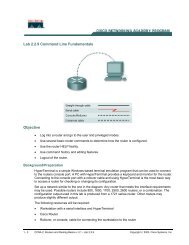
<strong>M16C</strong> Family-related document listUsages(Microcomputer development flow)Selection ofmicrocomputerOutline designof systemDetail designof systemHardwaredevelopmentSoftwaredevelopmentHardwareSoftwareType of documentData sheet anddata book<strong>User</strong>’s manualProgrammingmanualSoftware manualContentsHardware specifications (pin assignment,memory map, specifications of peripheral functions,electrical characteristics, timing charts)Detailed description about hardware specifications,operation, and application examples(connection with peripherals, relationship withsoftware)Method for creating programs using assemblyand C languagesDetailed description about operation of eachinstruction (assembly language)Systemevaluation<strong>M16C</strong> Family Line-up<strong>M16C</strong> Family <strong>M16C</strong>/80 Series <strong>M16C</strong>/80 Group<strong>M16C</strong>/60 Series<strong>M16C</strong>/60 Group<strong>M16C</strong>/61 Group<strong>M16C</strong>/62 Group<strong>M16C</strong>/20 Series<strong>M16C</strong>/20 Group<strong>M16C</strong>/21 Group<strong>M16C</strong>/22 Group
Table of ContentsChapter 1 Hardware ________________________________________Description ............................................................................................................................................2Memory ...............................................................................................................................................11Central Processing Unit (CPU) ...........................................................................................................12Reset...................................................................................................................................................15Memory Space Expansion Features ...................................................................................................22Processor Mode ..................................................................................................................................28Bus Settings ........................................................................................................................................32Bus Control .........................................................................................................................................34Clock Generating Circuit .....................................................................................................................41Protection ............................................................................................................................................50Overview of Interrupt...........................................................................................................................51______NMI Interrupt .......................................................................................................................................67Watchdog Timer..................................................................................................................................71DMAC .................................................................................................................................................73Timer ...................................................................................................................................................83Timer A ...............................................................................................................................................85Timer B ...............................................................................................................................................95Timers' function for three-phase motor control .................................................................................101Serial I/O ...........................................................................................................................................113Clock synchronous serial I/O mode ..................................................................................................122Clock asynchronous serial I/O mode ................................................................................................129UART2 Special Mode Register .........................................................................................................141SI/O3,4 ..............................................................................................................................................149A-D Converter ...................................................................................................................................153D-A Converter ...................................................................................................................................163CRC Calculation Circuit ....................................................................................................................165Programmable I/O Ports ...................................................................................................................167Flash .................................................................................................................................................235Chapter 2 Peripheral Functions Usage ________________________2.1 Protect ........................................................................................................................................276
2.1.1 Overview ..............................................................................................................................2762.1.2 Protect Operation.................................................................................................................2782.2 Timer A .......................................................................................................................................2802.2.1 Overview ..............................................................................................................................2802.2.2 Operation of Timer A (timer mode) ......................................................................................2862.2.3 Operation of Timer A (timer mode, gate function selected) .................................................2882.2.4 Operation of Timer A (timer mode, pulse output function selected) ....................................2902.2.5 Operation of Timer A (event counter mode, reload type selected) ......................................2922.2.6 Operation of Timer A (event counter mode, free run type selected)....................................2942.2.7 Operation of timer A (2-phase pulse signal process in event counter mode, nomal mode) ............2962.2.8 Operation of timer A (2-phase pulse signal process in event counter mode, multiply by-4mode selected .....................................................................................................................2982.2.9 Operation of Timer A (one-shot timer mode) .......................................................................3002.2.10 Operation of Timer A (one-shot timer mode, external trigger selected) .............................3022.2.11 Operation of Timer A (pulse width modulation mode, 16-bit PWM mode selected) ..........3042.2.12 Operation of Timer A (pulse width modulation mode, 8-bit PWM mode selected) ............3062.2.13 Precautions for Timer A (timer mode) ................................................................................3082.2.14 Precautions for Timer A (event counter mode) ..................................................................3092.2.15 Precautions for Timer A (one-shot timer mode) .................................................................3102.2.16 Precautions for Timer A (pulse width modulation mode) ...................................................3112.3 Timer B .......................................................................................................................................3122.3.1 Overview ..............................................................................................................................3122.3.2 Operation of Timer B (timer mode) ......................................................................................3162.3.3 Operation of Timer B (event counter mode) ........................................................................3182.3.4 Operation of Timer B (pulse period measurement mode) ...................................................3202.3.5 Operation of Timer B (pulse width measurement mode) .....................................................3222.3.6 Precautions for Timer B (timer mode, event counter mode) ................................................3242.3.7 Precautions for Timer B (pulse period/pulse width measurement mode) ........................... 3252.4 Clock-Synchronous Serial I/O .....................................................................................................3262.4.1 Overview ..............................................................................................................................3262.4.2 Operation of Serial I/O (transmission in clock-synchronous serial I/O mode) ..................... 3342.4.3 Operation of the Serial I/O (transmission in clock-synchronous serial I/O mode,transfer clock output from multiple pins function selected) ....................................................3382.4.4 Operation of Serial I/O (reception in clock-synchronous serial I/O mode) ........................... 3422.4.5 Precautions for Serial I/O (in clock-synchronous serial I/O) ................................................346
2.5 Clock-Asynchronous Serial I/O (UART) ......................................................................................3482.5.1 Overview ..............................................................................................................................3482.5.2 Operation of Serial I/O (transmission in UART mode) .........................................................3582.5.3 Operation of Serial I/O (reception in UART mode) ..............................................................3622.5.4 Operation of Serial I/O (transmission compliant with SIM interface) ...................................3662.5.5 Operation of Serial I/O (reception compliant with SIM interface) .........................................3702.5.6 Clock Signals in compliance with the SIM Interface ............................................................3742.6 SI/O3,4 ........................................................................................................................................3782.6.1 Overview ..............................................................................................................................3782.6.2 Operationof SI/O3,4 .............................................................................................................3802.7 A-D Converter .............................................................................................................................3822.7.1 Overview ..............................................................................................................................3822.7.2 Operation of A-D converter (one-shot mode) ......................................................................3882.7.3 Operation of A-D Converter (in one-shot mode, an external trigger selected) ....................3902.7.4 Operation of A-D Converter (in one-shot mode, expanded analog input pin selected) .......3922.7.5 Operation of A-D Converter (in one-shot mode,external op-amp connection mode selected) ..................................................................3942.7.6 Operation of A-D Converter (in repeat mode)......................................................................3962.7.7 Operation of A-D Converter (in single sweep mode) ...........................................................3982.7.8 Operation of A-D Converter (in repeat sweep mode 0) .......................................................4002.7.9 Operation of A-D Converter (in repeat sweep mode 1) .......................................................4022.7.10 Precautions for A-D Converter...........................................................................................4042.7.11 Method of A-D Conversion (10-bit mode) ..........................................................................4052.7.12 Method of A-D Conversion (8-bit mode) ............................................................................4072.7.13 Absolute Accuracy and Differential Non-Linearity Error ....................................................4092.7.14 Internal Equivalent Circuit of Analog Input.........................................................................4112.7.15 Sensor’s Output Impedance under A-D Conversion..........................................................4122.8 D-A Converter .............................................................................................................................4142.8.1 Overview ..............................................................................................................................4142.8.2 D-A Converter Operation .....................................................................................................4152.9 DMAC .........................................................................................................................................4162.9.1 Overview ..............................................................................................................................4162.9.2 Operation of DMAC (one-shot transfer mode) .....................................................................4202.9.3 Operation of DMAC (repeated transfer mode) .....................................................................4222.10 CRC Calculation Circuit ............................................................................................................424
2.10.1 Overview ............................................................................................................................4242.10.2 Operation of CRC Calculation Circuit ................................................................................4252.11 Watchdog Timer .......................................................................................................................4262.11.1 Overview ............................................................................................................................4262.11.2 Operation of Watchdog Timer............................................................................................4282.12 Address Match Interrupt ...........................................................................................................4302.12.1 Overview ............................................................................................................................4302.12.2 Operation of Address Match Interrupt................................................................................4322.13 Key-Input Interrupt ....................................................................................................................4342.13.1 Overview ............................................................................................................................4342.13.2 Operation of Key-Input Interrupt ........................................................................................4362.14 Power Control ...........................................................................................................................4382.14.1 Overview ............................................................................................................................4382.14.2 Stop Mode Set-Up .............................................................................................................4432.14.3 Wait Mode Set-Up .............................................................................................................4442.14.4 Precautions in Saving Power .............................................................................................4452.15 Programmable I/O Ports ...........................................................................................................4462.15.1 Overview ............................................................................................................................446Chapter 3 Examples of Peripheral functions Applications ________3.1 Long-Period Timers ....................................................................................................................4563.2 Variable-Period Variable-Duty PWM Output ...............................................................................4603.3 Delayed One-Shot Output ..........................................................................................................4643.4 Buzzer Output .............................................................................................................................4683.5 Solution for External Interrupt Pins Shortage .............................................................................4703.6 Memory to Memory DMA Transfer..............................................................................................4723.7 Controlling Power Using Stop Mode ...........................................................................................4763.8 Controling Power Using Wait Mode ............................................................................................480Chapter 4 Interrupt_________________________________________4.1 Overview of Interrupt ..................................................................................................................4864.1.1 Type of Interrupts.................................................................................................................4864.1.2 Software Interrupts ..............................................................................................................4874.1.3 Hardware Interrupts .............................................................................................................4884.1.4 Interrupts and Interrupt Vector Tables .................................................................................4894.2 Interrupt Control ..........................................................................................................................491
4.2.1 Interrupt Enable Flag ...........................................................................................................4934.2.2 Interrupt Request Bit ............................................................................................................4934.2.3 Changing the Interrupt Control Register ..............................................................................4944.2.4 Interrupt Priority Level Select Bit and Processor Interrupt Priority Level (IPL) ....................4954.3 Interrupt Sequence .....................................................................................................................4964.3.1 Interrupt Response Time .....................................................................................................4964.3.2 Variation of IPL when Interrupt Request is Accepted ..........................................................4974.3.3 Saving Registers ..................................................................................................................4984.4 Returning from an Interrupt Routine ...........................................................................................5004.5 Interrupt Priority ..........................................................................................................................5004.6 Multiple Interrupts .......................................................................................................................5024.7 Precautions for Interrupts ...........................................................................................................504Chapter 5 External Buses __________________________________5.1 Overview of External Buses ........................................................................................................5085.2 Data Access ................................................................................................................................5095.2.1 Data Bus Width ....................................................................................................................5095.2.2 Chip Selects and Address Bus ............................................................................................5105.2.3 Bus Types ...........................................................................................................................5115.2.4 R/W Modes .........................................................................................................................5115.3 Memory Space Expansion Features ...........................................................................................5125.3.1 Normal Mode .......................................................................................................................5135.3.2 Memory Space Expansion Mode 1 ......................................................................................5145.3.3 Memory Space Expansion Mode 2 .....................................................................................5155.4 Connection Examples .................................................................................................................5215.4.1 16-bit Memory to 16-bit Width Data Bus Connection Example ............................................5215.4.2 8-bit Memory to 16-bit Width Data Bus Connection Example..............................................5225.4.3 8-bit Memory to 8-bit Width Data Bus Connection Example...............................................5245.4.4 Two 8-bit and 16-Bit Memory to 16-Bit Width Data Bus Connection Example ....................5255.4.5 16-bit Width Data Bus Connection Example in Memory Space Expansion Mode 1 ............5265.4.6 8-bit Width Data Bus Connection Example in Memory Space Expansion Mode 1 .............5275.4.7 8-bit Width Data Bus Connection Example in Memory Space Expansion Mode 2 .............5285.4.8 Chip Selects and Address Bus ............................................................................................5295.5 Connectable Memories ...............................................................................................................5305.5.1 Operation Frequency and Access Time ..............................................................................530
5.5.2 Connecting Low-Speed Memory .........................................................................................5345.5.3 Connectable Memories ........................................................................................................538___________________5.6 Releasing an External Bus (HOLD input and HLDA output) .......................................................5405.7 Precautions for External Bus ......................................................................................................541Chapter 6 External ROM Version_____________________________6.1 Pin Configuration ........................................................................................................................5456.2 Pin Description ............................................................................................................................5476.3 Memory Map ...............................................................................................................................5496.4 Processor Mode ..........................................................................................................................553Chapter 7 Standard Characteristics __________________________7.1 Standard DC Characteristics ......................................................................................................5567.1.1 Standard Ports Characteristics ............................................................................................5567.1.2 Standard Characteristics of ICC-f(XIN) ...................................................................................5597.2 Standard Characteristics of A-D Converter ................................................................................5617.3 Standard Characteristics of D-A Converter ................................................................................5637.4 Standard Characteristics of Pull-Up Resistor .............................................................................566
Quick Reference to Pages Classified by AddressAddress Register Page000016000116000216000316000416000516000616000716000816000916000A16000B16000C16000D16000E16000F16001016001116001216001316001416001516001616001716001816001916001A16001B16001C16001D16001E16001F16002016002116002216002316002416002516002616002716002816002916002A16002B16002C16002D16002E16002F16003016003116003216003316003416003516003616003716003816003916003A16003B16003C16003D16003E16003F16Processor mode register 0 (PM0)Processor mode register 1(PM1)System clock control register 0 (CM0)System clock control register 1 (CM1)Chip select control register (CSR)Address match interrupt enable register (AIER)Protect register (PRCR)Data bank register (DBR)Watchdog timer start register (WDTS)Watchdog timer control register (WDC)Address match interrupt register 0 (RMAD0)Address match interrupt register 1 (RMAD1)DMA0 source pointer (SAR0)DMA0 destination pointer (DAR0)DMA0 transfer counter (TCR0)DMA0 control register (DM0CON)DMA1 source pointer (SAR1)DMA1 destination pointer (DAR1)DMA1 transfer counter (TCR1)DMA1 control register (DM1CON)2943356849257268687777777677777776Address Register Page004016004116004216004316004416004516004616004716004816004916004A16004B16004C16004D16004E16004F16005016005116005216005316005416005516005616005716005816005916005A16005B16005C16005D16005E16005F16006016006116006216006316006416006516032A16032B16032C16032D16032E16032F16033016033116033216033316033416033516033616033716033816033916033A16033B16033C16033D16033E16033F16INT3 interrupt control register (INT3IC)Timer B5 interrupt control register (TB5IC)Timer B4 interrupt control register (TB4IC)Timer B3 interrupt control register (TB3IC)SI/O4 interrupt control register (S4IC)INT5 interrupt control register (INT5IC)SI/O3 interrupt control register (S3IC)INT4 interrupt control register (INT4IC)Bus collision detection interrupt control register (BCNIC)DMA0 interrupt control register (DM0IC)DMA1 interrupt control register (DM1IC)Key input interrupt control register (KUPIC)A-D conversion interrupt control register (ADIC)UART2 transmit interrupt control register (S2TIC)UART2 receive interrupt control register (S2RIC)UART0 transmit interrupt control register (S0TIC)UART0 receive interrupt control register (S0RIC)UART1 transmit interrupt control register (S1TIC)UART1 receive interrupt control register (S1RIC)Timer A0 interrupt control register (TA0IC)Timer A1 interrupt control register (TA1IC)Timer A2 interrupt control register (TA2IC)Timer A3 interrupt control register (TA3IC)Timer A4 interrupt control register (TA4IC)Timer B0 interrupt control register (TB0IC)Timer B1 interrupt control register (TB1IC)Timer B2 interrupt control register (TB2IC)INT0 interrupt control register (INT0IC)INT1 interrupt control register (INT1IC)INT2 interrupt control register (INT2IC)57Note 1: Locations in the SFR area where nothing is allocated are reserved areas. Do not access these areas for read or write.
Quick Reference to Pages Classified by AddressAddress Register Page Address Register Page034016034116Timer B3, 4, 5 count start flag (TBSR)96 038016038116Count start flag (TABSR)Clock prescaler reset flag (CPSRF)86034216038216 One-shot start flag (ONSF)Timer A1-1 register (TA11)034316038316 Trigger select register (TRGSR)034416038416 Up-down flag (UDF)Timer A2-1 register (TA21)1030345160385168786034616034716034816034916034A16034B16034C16034D16034E16034F16035016035116035216035316035416035516035616035716035816035916035A16035B16035C16035D16035E16035F16036016036116036216036316036416036516036616036716036816036916036A16036B16036C16036D16036E16036F16037016037116037216037316037416037516037616037716037816037916037A16037B16037C16037D16037E16037F16Timer A4-1 register (TA41)Three-phase PWM control register 0(INVC0)Three-phase PWM control register 1(INVC1)Three-phase output buffer register 0(IDB0)Three-phase output buffer register 1(IDB1)Dead time timer(DTT)Timer B2 interrupt occurrence frequency set counter(ICTB2)Timer B3 register (TB3)Timer B4 register (TB4)Timer B5 register (TB5)Timer B3 mode register (TB3MR)Timer B4 mode register (TB4MR)Timer B5 mode register (TB5MR)Interrupt cause select register (IFSR)SI/O3 transmit/receive register (S3TRR)SI/O3 control register (S3C)SI/O3 bit rate generator (S3BRG)SI/O4 transmit/receive register (S4TRR)SI/O4 control register (S4C)SI/O4 bit rate generator (S4BRG)UART2 special mode register 2(U2SMR2)UART2 special mode register (U2SMR)UART2 transmit/receive mode register (U2MR)UART2 bit rate generator (U2BRG)UART2 transmit buffer register (U2TB)UART2 transmit/receive control register 0 (U2C0)UART2 transmit/receive control register 1 (U2C1)UART2 receive buffer register (U2RB)101102969565150141121118117119120117038616038716038816038916038A16038B16038C16038D16038E16038F16039016039116039216039316039416039516039616039716039816039916039A16039B16039C16039D16039E16039F1603A01603A11603A21603A31603A41603A51603A61603A71603A81603A91603AE1603AF1603B01603B11603B21603B31603B41603B51603B61603B71603B81603B91603BA1603BB1603BC1603BD1603BE1603BF16Timer A0 (TA0)Timer A1 (TA1)Timer A2 (TA2)Timer A3 (TA3)Timer A4 (TA4)Timer B0 (TB0)Timer B1 (TB1)Timer B2 (TB2)Timer A0 mode register (TA0MR)Timer A1 mode register (TA1MR)Timer A2 mode register (TA2MR)Timer A3 mode register (TA3MR)Timer A4 mode register (TA4MR)Timer B0 mode register (TB0MR)Timer B1 mode register (TB1MR)Timer B2 mode register (TB2MR)UART0 transmit/receive mode register (U0MR)UART0 bit rate generator (U0BRG)UART0 transmit buffer register (U0TB)UART0 transmit/receive control register 0 (U0C0)UART0 transmit/receive control register 1 (U0C1)UART0 receive buffer register (U0RB)UART1 transmit/receive mode register (U1MR)UART1 bit rate generator (U1BRG)03AA1603AB16UART1 transmit buffer register (U1TB)03AC16 UART1 transmit/receive control register 0 (U1C0)03AD16 UART1 transmit/receive control register 1 (U1C1)UART1 receive buffer register (U1RB)UART transmit/receive control register 2 (UCON)Flash memory control register 1 (FMR1) (Note 1)Flash memory control register 0 (FMR0) (Note 1)DMA0 request cause select register (DM0SL)DMA1 request cause select register (DM1SL)CRC data register (CRCD)CRC input register (CRCIN)869685951181171191201171181171191201171212407576165Note 1 : This register is only exist in flash memory version.Note 2 : Locations in the SFR area where nothing is allocated are reserved areas. Do not access these areas for read or write.
Quick Reference to Pages Classified by AddressAddress Register Page03C01603C11603C21603C31603C41603C51603C61603C71603C81603C91603CA1603CB1603CC1603CD1603CE1603CF1603D01603D11603D21603D31603D41603D51603D61603D71603D81603D91603DA1603DB1603DC1603DD1603DE1603DF1603E01603E11603E21603E31603E41603E51603E61603E71603E81603E91603EA1603EB1603EC1603ED1603EE1603EF1603F01603F11603F21603F31603F41603F51603F61603F71603F81603F91603FA1603FB1603FC1603FD1603FE1603FF16A-D register 0 (AD0)A-D register 1 (AD1)A-D register 2 (AD2)A-D register 3 (AD3)A-D register 4 (AD4)A-D register 5 (AD5)A-D register 6 (AD6)A-D register 7 (AD7)A-D control register 2 (ADCON2)A-D control register 0 (ADCON0)A-D control register 1 (ADCON1)D-A register 0 (DA0)D-A register 1 (DA1)D-A control register (DACON)Port P0 (P0)Port P1 (P1)Port P0 direction register (PD0)Port P1 direction register (PD1)Port P2 (P2)Port P3 (P3)Port P2 direction register (PD2)Port P3 direction register (PD3)Port P4 (P4)Port P5 (P5)Port P4 direction register (PD4)Port P5 direction register (PD5)Port P6 (P6)Port P7 (P7)Port P6 direction register (PD6)Port P7 direction register (PD7)Port P8 (P8)Port P9 (P9)Port P8 direction register (PD8)Port P9 direction register (PD9)Port P10 (P10)Port P10 direction register (PD10)Pull-up control register 0 (PUR0)Pull-up control register 1 (PUR1)Pull-up control register 2 (PUR2)Port control register (PCR)156156155164173172173172173172173172173172173172174175Note : Locations in the SFR area where nothing is allocated are reservedareas. Do not access these areas for read or write.
Chapter 1Hardware
DescriptionMitsubishi microcomputers<strong>M16C</strong> / 62 GroupSINGLE-CHIP 16-BIT CMOS MICROCOMPUTERDescriptionThe <strong>M16C</strong>/62 group of single-chip microcomputers are built using the high-performance silicon gate CMOSprocess using a <strong>M16C</strong>/60 Series CPU core and are packaged in a 100-pin plastic molded QFP. Thesesingle-chip microcomputers operate using sophisticated instructions featuring a high level of instructionefficiency. With 1M bytes of address space, they are capable of executing instructions at high speed. Theyalso feature a built-in multiplier and DMAC, making them ideal for controlling office, communications, industrialequipment, and other high-speed processing applications.The <strong>M16C</strong>/62 group includes a wide range of products with different internal memory types and sizes andvarious package types.Features• Memory capacity..................................ROM (See Figure 1.1.4. ROM Expansion)RAM 3K to 20K bytes• Shortest instruction execution time ......62.5ns (f(XIN)=16MHZ, VCC=5V)100ns (f(XIN)=10MHZ, VCC=3V, with software one-wait) : Mask ROM, flash memory 5V version142.9ns (f(XIN)=7MHZ, VCC=3V, with software one-wait) : One-time PROM version• Supply voltage ..................................... 4.2 to 5.5V (f(XIN)=16MHZ, without software wait) : Mask ROM, flash memory 5V version4.5 to 5.5V (f(XIN)=16MHZ, without software wait) : One-time PROM version2.7 to 5.5V (f(XIN)=10MHZ with software one-wait) : Mask ROM, flash memory 5V version2.7 to 5.5V (f(XIN)=7MHZ with software one-wait) : One-time PROM version• Low power consumption ......................25.5mW ( f(XIN)=10MHZ, with software one-wait, VCC = 3V)• Interrupts..............................................25 internal and 8 external interrupt sources, 4 softwareinterrupt sources; 7 levels (including key input interrupt)• Multifunction 16-bit timer......................5 output timers + 6 input timers• Serial I/O ..............................................5 channels (3 for UART or clock synchronous, 2 for clock synchronous)• DMAC ..................................................2 channels (trigger: 24 sources)• A-D converter.......................................10 bits X 8 channels (Expandable up to 10 channels)• D-A converter.......................................8 bits X 2 channels• CRC calculation circuit.........................1 circuit• Watchdog timer....................................1 line• Programmable I/O ...............................87 lines_______• Input port.............................................. 1 line (P85 shared with NMI pin)• Memory expansion ..............................Available (to 1.2M bytes or 4M bytes)• Chip select output ................................4 lines• Clock generating circuit .......................2 built-in clock generation circuits(built-in feedback resistor, and external ceramic or quartz oscillator)ApplicationsAudio, cameras, office equipment, communications equipment, portable equipmentCentral Processing Unit (CPU) ..................... 12Reset ............................................................. 15Processor Mode ............................................ 28Clock Generating Circuit ............................... 41Protection ...................................................... 49Interrupts ....................................................... 51Watchdog Timer ............................................ 71DMAC ........................................................... 73------Table of Contents------Timer ............................................................. 83Serial I/O ..................................................... 113A-D Converter ............................................. 153D-A Converter ............................................. 163CRC Calculation Circuit .............................. 165Programmable I/O Ports ............................. 167Electrical characteristic ............................... 182Flash memory version ................................. 2352
DescriptionMitsubishi microcomputers<strong>M16C</strong> / 62 GroupSINGLE-CHIP 16-BIT CMOS MICROCOMPUTERPin ConfigurationFigures 1.1.1 and 1.1.2 show the pin configurations (top view).PIN CONFIGURATION (top view)P10/D8P11/D9P12/D10P13/D11P14/D12P15/D13/INT3P16/D14/INT4P17/D15/INT5P20/A0(/D0/-)P21/A1(/D1/D0)P22/A2(/D2/D1)P23/A3(/D3/D2)P24/A4(/D4/D3)P25/A5(/D5/D4)P26/A6(/D6/D5)P27/A7(/D7/D6)VssP30/A8(/-/D7)VccP31/A9P32/A10P33/A11P34/A12P35/A13P36/A14P37/A15P40/A16P41/A17P42/A18P43/A19P07/D7P06/D6P05/D5P04/D4P03/D3P02/D2P01/D1P00/D0P107/AN7/KI3P106/AN6/KI2P105/AN5/KI1P104/AN4/KI0P103/AN3P102/AN2P101/AN1AVSSP100/AN0VREFAVccP97/ADTRG/SIN48182838485868788899091929394959697989910080 79 78 77 76 75 74 73 72 71 70 69 68 67 66 65 64 63 62 61 60 59 58 57 56 55 54 53 52 51<strong>M16C</strong>/62 Group5049484746454443424140393837363534333231P44/CS0P45/CS1P46/CS2P47/CS3P50/WRL/WRP51/WRH/BHEP52/RDP53/BCLKP54/HLDAP55/HOLDP56/ALEP57/RDY/CLKOUTP60/CTS0/RTS0P61/CLK0P62/RxD0P63/TXD0P64/CTS1/RTS1/CTS0/CLKS1P65/CLK1P66/RxD1P67/TXD11 2 3 4 5 6 7 8 9 101112131415161718192021222324252627282930P96/ANEX1/SOUT4P95/ANEX0/CLK4P94/DA1/TB4INP93/DA0/TB3INP91/TB1IN/SIN3P92/TB2IN/SOUT3P90/TB0IN/CLK3BYTECNVssP87/XCINP86/XCOUTRESETXOUTVSSXINVCCP85/NMIP84/INT2P83/INT1P82/INT0P81/TA4IN/UP80/TA4OUT/UP77/TA3INP76/TA3OUTP75/TA2IN/WP74/TA2OUT/WP73/CTS2/RTS2/TA1IN/VP72/CLK2/TA1OUT/VP71/RxD2/SCL/TA0IN/TB5INP70/TXD2/SDA/TA0OUTPackage: 100P6S-AFigure 1.1.1. Pin configuration (top view)3
DescriptionMitsubishi microcomputers<strong>M16C</strong> / 62 GroupSINGLE-CHIP 16-BIT CMOS MICROCOMPUTERPIN CONFIGURATION (top view)P12/D10P11/D9P10/D8P07/D7P06/D6P05/D5P04/D4P03/D3P02/D2P01/D1P00/D0P107/AN7/KI3P106/AN6/KI2P105/AN5/KI1P104/AN4/KI0P103/AN3P102/AN2P101/AN1AVSSP100/AN0VREFAVccP97/ADTRG/SIN4P96/ANEX1/SOUT4P95/ANEX0/CLK4767778798081828384858687888990919293949596979899100P13/D11P14/D12P15/D13/INT3P16/D14/INT4P17/D15/INT5P90/TB0IN/CLK3BYTE P20/A0(/D0/-)CNVssP21/A1(/D1/D0)P22/A2(/D2/D1)P23/A3(/D3/D2)P24/A4(/D4/D3)P25/A5(/D5/D4)P26/A6(/D6/D5)P27/A7(/D7/D6)75 74 73 72 71 70 69 68 67 66 65 64 63 62 61 60 59 58 57 56 55 54 53 52 511 2 3 4 5 6 7 8 9 101112131415161718192021 22 23 24 25P94/DA1/TB4INP93/DA0/TB3INP91/TB1IN/SIN3P92/TB2IN/SOUT3P87/XCINP86/XCOUTRESETXOUTVSSXINVCCVssP30/A8(/-/D7)VccP31/A9P32/A10<strong>M16C</strong>/62 GroupP85/NMIP84/INT2P83/INT1P82/INT0P33/A11P34/A12P35/A13P36/A14P37/A15P40/A16P41/A17P81/TA4IN/UP80/TA4OUT/UP77/TA3INP76/TA3OUTP75/TA2IN/WP74/TA2OUT/WP73/CTS2/RTS2/TA1IN/V50494847464544434241403938373635343332313029282726P42/A18P43/A19P44/CS0P45/CS1P46/CS2P47/CS3P50/WRL/WRP51/WRH/BHEP52/RDP53/BCLKP54/HLDAP55/HOLDP56/ALEP57/RDY/CLKOUTP60/CTS0/RTS0P61/CLK0P62/RxD0P63/TXD0P64/CTS1/RTS1/CTS0/CLKS1P65/CLK1P66/RxD1P67/TXD1P70/TXD2/SDA/TA0OUTP71/RxD2/SCL/TA0IN/TB5INP72/CLK2/TA1OUT/VPackage: 100P6Q-AFigure 1.1.2. Pin configuration (top view)4
DescriptionMitsubishi microcomputers<strong>M16C</strong> / 62 GroupSINGLE-CHIP 16-BIT CMOS MICROCOMPUTERBlock DiagramFigure 1.1.3 is a block diagram of the <strong>M16C</strong>/62 group.Block diagram of the <strong>M16C</strong>/62 group8888888I/O portsPort P0Port P1Port P2Port P3Port P4Port P5Port P6Internal peripheral functionsTimerTimer TA0 (16 bits)Timer TA1 (16 bits)Timer TA2 (16 bits)Timer TA3 (16 bits)Timer TA4 (16 bits)Timer TB0 (16 bits)Timer TB1 (16 bits)Timer TB2 (16 bits)Timer TB3 (16 bits)Timer TB4 (16 bits)Timer TB5 (16 bits)Watchdog timer(15 bits)DMAC(2 channels)D-A converter(8 bits X 2 channels)Note 1: ROM size depends on MCU type.Note 2: RAM size depends on MCU type.A-D converter(10 bits X 8 channelsExpandable up to 10 channels)UART/clock synchronous SI/O(8 bits X 3 channels)CRC arithmetic circuit (CCITT )(Polynomial : X 16 +X 12 +X 5 +1)<strong>M16C</strong>/60 series16-bit CPU coreRegistersR0H R0LR0H R0LR1H R1LR1H R1LR2R2R3R3A0A0A1A1FBFBSBProgram counterPCVector tableINTBStack pointerISPUSPFlag registerFLGSystem clock generatorXIN-XOUTXCIN-XCOUTClock synchronous SI/O(8 bits X 2 channels)MemoryROM(Note 1)RAM(Note 2)MultiplierPort P7Port P8Port P85Port P9Port P1087 8 8Figure 1.1.3. Block diagram of <strong>M16C</strong>/62 group5
DescriptionMitsubishi microcomputers<strong>M16C</strong> / 62 GroupSINGLE-CHIP 16-BIT CMOS MICROCOMPUTERPerformance OutlineTable 1.1.1 is a performance outline of <strong>M16C</strong>/62 group.Table 1.1.1. Performance outline of <strong>M16C</strong>/62 groupItemPerformanceNumber of basic instructions91 instructionsShortest instruction execution time62.5ns(f(XIN)=16MHZ, VCC=5V)100ns (f(XIN)=10MHZ, VCC=3V, with software one-wait): Mask ROM, flash memory 5V version142.9ns (f(XIN)=7MHZ, VCC=3V, with software one-wait): One-time PROM versionMemory ROM (See the figure 1.1.4. ROM Expansion)capacity RAM 3K to 20K bytesI/O port P0 to P10 (except P85) 8 bits x 10, 7 bits x 1Input port P85 1 bit x 1Multifunction TA0, TA1, TA2, TA3, TA4 16 bits x 5timer TB0, TB1, TB2, TB3, TB4, TB5 16 bits x 6Serial I/O UART0, UART1, UART2 (UART or clock synchronous) x 3SI/O3, SI/O4 (Clock synchronous) x 2A-D converter10 bits x (8 + 2) channelsD-A converter 8 bits x 2DMAC2 channels (trigger: 24 sources)CRC calculation circuitCRC-CCITTWatchdog timer15 bits x 1 (with prescaler)Interrupt25 internal and 8 external sources, 4 software sources, 7 levelsClock generating circuit2 built-in clock generation circuits(built-in feedback resistor, and external ceramic or quartz oscillator)Supply voltage4.2 to 5.5V (f(XIN)=16MHZ, without software wait): Mask ROM, flash memory 5V version4.5 to 5.5V (f(XIN)=16MHZ, without software wait): One-time PROM version2.7 to 5.5V (f(XIN)=10MHZ with software one-wait): Mask ROM, flash memory 5V version2.7 to 5.5V (f(XIN)=7MHZ with software one-wait): One-time PROM versionPower consumption25.5mW (f(XIN) = 10MHZ, VCC=3V with software one-wait)I/O I/O withstand voltage 5Vcharacteristics Output current 5mAMemory expansionAvailable (to 1.2M bytes or 4M bytes)Device configurationCMOS high performance silicon gatePackage100-pin plastic mold QFP6
DescriptionMitsubishi microcomputers<strong>M16C</strong> / 62 GroupSINGLE-CHIP 16-BIT CMOS MICROCOMPUTERMitsubishi plans to release the following products in the <strong>M16C</strong>/62 group:(1) Support for mask ROM version, external ROM version, one-time PROM version, EPROM version, andFlash memory version(2) ROM capacity(3) Package100P6S-A : Plastic molded QFP (mask ROM, one-time PROM, and flash memory versions)100P6Q-A : Plastic molded QFP(mask ROM, one-time PROM, and flash memory versions)100D0 : Ceramic LCC (EPROM version)ROM Size(Byte)ExternalROM256K M30624MG-XXXFP/GPM30620MC-XXXFP/GP128KM30622MC-XXXFP/GPM30620MA-XXXFP/GP96KM30622MA-XXXFP/GPM30620M8-XXXFP/GP64K M30622M8-XXXFP/GPM30620ECFP/GPM30620ECFSM30624FGFP/GPM30624FGLFP/GPM30620SFP/GPM30622SFP/GP32KM30622M4-XXXFP/GPMask ROM version One-time PROM version EPROM version Flash memory versionExternal ROM versionFigure 1.1.4. ROM expansionThe <strong>M16C</strong>/62 group products currently supported are listed in Table 1.1.2.Table 1.1.2. <strong>M16C</strong>/62 groupNovember. 1999Type No ROM capacity RAM capacity Package type RemarksM30622M4-XXXFP32K byte 3K byte100P6S-AM30622M4-XXXGP100P6Q-AM30620M8-XXXFP100P6S-A10K byteM30620M8-XXXGP100P6Q-A64K byteM30622M8-XXXFP100P6S-A4K byteM30622M8-XXXGP100P6Q-AM30620MA-XXXFP10K byte100P6S-AM30620MA-XXXGP100P6Q-A96K bytemask ROM versionM30622MA-XXXFP100P6S-A5K byteM30622MA-XXXGP100P6Q-AM30620MC-XXXFP100P6S-A10K byteM30620MC-XXXGP100P6Q-A128K byteM30622MC-XXXFP100P6S-A5K byteM30622MC-XXXGP100P6Q-AM30624MG-XXXFP100P6S-A256K byte 20K byteM30624MG-XXXGP100P6Q-AM30620ECFP100P6S-A128K byte 10K byteM30620ECGP100P6Q-AOne-time PROM versionM30620ECFS 128K byte 10K byte 100D0EPROM version (Note)M30624FGFP100P6S-A Flash memory256K byte 20K byteM30624FGGP100P6Q-A 5V versionM30624FGLFP100P6S-A Flash memory256K byte 20K byteM30624FGLGP100P6Q-A 3V versionM30620SFP100P6S-A10K byteM30620SGP100P6Q-AExternal ROM versionM30622SFP100P6S-A3K byteM30622SGP100P6Q-ANote: Do not use the EPROM version for mass production, because it is a tool for program development(for evaluation).7
DescriptionMitsubishi microcomputers<strong>M16C</strong> / 62 GroupSINGLE-CHIP 16-BIT CMOS MICROCOMPUTERType No.M 3 0 6 2 2 M 8 – X X X F PPackage type:FP : PackageGP :FS :100P6S-A100P6Q-A100D0ROM No.Omitted for blank one-time PROM version,andEPROM version, and flash memory versionROM capacity:4 : 32K bytes8 : 64K bytesA : 96K bytesC : 128K bytesG: 256K bytesMemory type:M : Mask ROM versionE : EPROM or one-time PROM versionS : External ROM versionF : Flash memory versionShows RAM capacity, pin count, etc(The value itself has no specific meaning)<strong>M16C</strong>/62 Group<strong>M16C</strong> FamilyFigure 1.1.5. Type No., memory size, and package8
Pin DescriptionMitsubishi microcomputers<strong>M16C</strong> / 62 GroupSINGLE-CHIP 16-BIT CMOS MICROCOMPUTERPin DescriptionPin nameSignal nameI/O typeFunctionVCC, VSSPower supplyinputSupply 2.7 to 5.5 V to the VCC pin. Supply 0 V to the VSS pin.CNVSSCNVSSInputThis pin switches between processor modes. Connect this pin to theVSS pin when after a reset you want to start operation in single-chipmode (memory expansion mode) or the VCC pin when startingoperation in microprocessor mode.RESETReset inputInputA “L” on this input resets the microcomputer.XINXOUTClock inputClock outputInputOutputThese pins are provided for the main clock generating circuit.Connecta ceramic resonator or crystal between the XIN and the XOUT pins. Touse an externally derived clock, input it to the XIN pin and leave theXOUT pin open.BYTEExternal databus widthselect inputInputThis pin selects the width of an external data bus. A 16-bit width isselected when this input is “L”; an 8-bit width is selected when thisinput is “H”. This input must be fixed to either “H” or “L”. Connect thispin to the VSS pin when not using external data bus.AVCCAnalog powersupply inputThis pin is a power supply input for the A-D converter. Connect thispin to VCC.AVSSAnalog powersupply inputThis pin is a power supply input for the A-D converter. Connect thispin to VSS.VREFReferencevoltage inputInputThis pin is a reference voltage input for the A-D converter.P00 to P07I/O port P0Input/outputThis is an 8-bit CMOS I/O port. It has an input/output port directionregister that allows the user to set each pin for input or outputindividually. When used for input in single-chip mode, the port can beset to have or not have a pull-up resistor in units of four bits bysoftware. In memory expansion and microprocessor modes, selectionof the internal pull-resistor is not available.D0 to D7Input/outputWhen set as a separate bus, these pins input and output data (D0–D7).P10 to P17I/O port P1Input/outputThis is an 8-bit I/O port equivalent to P0. Pins in this port also functionas external interrupt pins as selected by software.D8 to D15Input/outputWhen set as a separate bus, these pins input and output data (D8–D15).P20 to P27I/O port P2Input/outputThis is an 8-bit I/O port equivalent to P0.A0 to A7OutputThese pins output 8 low-order address bits (A0–A7).A0/D0 toA7/D7Input/outputIf the external bus is set as an 8-bit wide multiplexed bus, these pinsinput and output data (D0–D7) and output 8 low-order address bits(A0–A7) separated in time by multiplexing.A0, A1/D0to A7/D6OutputInput/outputIf the external bus is set as a 16-bit wide multiplexed bus, these pinsinput and output data (D0–D6) and output address (A1–A7) separatedin time by multiplexing. They also output address (A0).P30 to P37I/O port P3Input/outputThis is an 8-bit I/O port equivalent to P0.A8 to A15OutputThese pins output 8 middle-order address bits (A8–A15).A8/D7,A9 to A15Input/outputOutputIf the external bus is set as a 16-bit wide multiplexed bus, these pinsinput and output data (D7) and output address (A8) separated in timeby multiplexing. They also output address (A9–A15).P40 to P47I/O port P4Input/outputThis is an 8-bit I/O port equivalent to P0.CS0 to CS3,A16 to A19OutputOutputThese pins output CS0–CS3 signals and A16–A19. CS0–CS3 are chipselect signals used to specify an access space. A16–A19 are 4 highorderaddress bits.9
Pin DescriptionMitsubishi microcomputers<strong>M16C</strong> / 62 GroupSINGLE-CHIP 16-BIT CMOS MICROCOMPUTERPin DescriptionPin nameSignal nameI/O typeFunctionP50 to P57I/O port P5Input/outputThis is an 8-bit I/O port equivalent to P0. In single-chip mode, P57 inthis port outputs a divide-by-8 or divide-by-32 clock of XIN or a clock ofthe same frequency as XCIN as selected by software.WRL / WR,WRH / BHE,RD,BCLK,HLDA,HOLD,ALE,RDYOutputOutputOutputOutputOutputInputOutputInputOutput WRL, WRH (WR and BHE), RD, BCLK, HLDA, and ALEsignals. WRL and WRH, and BHE and WR can be switched usingsoftware control.WRL, WRH, and RD selectedWith a 16-bit external data bus, data is written to even addresseswhen the WRL signal is “L” and to the odd addresses when the WRHsignal is “L”. Data is read when RD is “L”.WR, BHE, and RD selectedData is written when WR is “L”. Data is read when RD is “L”. Oddaddresses are accessed when BHE is “L”. Use this mode when usingan 8-bit external data bus.While the input level at the HOLD pin is “L”, the microcomputer isplaced in the hold state. While in the hold state, HLDA outputs a “L”level. ALE is used to latch the address. While the input level of theRDY pin is “L”, the microcomputer is in the ready state.P60 to P67I/O port P6Input/outputThis is an 8-bit I/O port equivalent to P0. When used for input in singlechip,memory expansion, and microprocessor modes, the port can beset to have or not have a pull-up resistor in units of four bits bysoftware. Pins in this port also function as UART0 and UART1 I/O pinsas selected by software.P70 to P77I/O port P7Input/outputThis is an 8-bit I/O port equivalent to P6 (P70 and P71 are N channelopen-drain output). Pins in this port also function as timer A0–A3,timer B5 or UART2 I/O pins as selected by software.P80 to P84,P86,P87,P85I/O port P8I/O port P85Input/outputInput/outputInput/outputInputP80 to P84, P86, and P87 are I/O ports with the same functions as P6.Using software, they can be made to function as the I/O pins for timerA4 and the input pins for external interrupts. P86 and P87 can be setusing software to function as the I/O pins for a sub clock generationcircuit. In this case, connect a quartz oscillator between P86 (XCOUTpin) and P87 (XCIN pin). P85 is an input-only port that also functionsfor NMI. The NMI interrupt is generated when the input at this pinchanges from “H” to “L”. The NMI function cannot be cancelled usingsoftware. The pull-up cannot be set for this pin.P90 to P97I/O port P9Input/outputThis is an 8-bit I/O port equivalent to P6. Pins in this port also functionas SI/O3, 4 I/O pins, Timer B0–B4 input pins, D-A converter output pins,A-D converter extended input pins, or A-D trigger input pins as selectedby software.P100 to P107I/O port P10Input/outputThis is an 8-bit I/O port equivalent to P6. Pins in this port also functionas A-D converter input pins. Furthermore, P104–P107 also function asinput pins for the key input interrupt function.10
MemoryMitsubishi microcomputers<strong>M16C</strong> / 62 GroupSINGLE-CHIP 16-BIT CMOS MICROCOMPUTEROperation of Functional BlocksThe <strong>M16C</strong>/62 group accommodates certain units in a single chip. These units include ROM and RAM tostore instructions and data and the central processing unit (CPU) to execute arithmetic/logic operations.Also included are peripheral units such as timers, serial I/O, D-A converter, DMAC, CRC calculation circuit,A-D converter, and I/O ports.The following explains each unit.MemoryFigure 1.4.1 is a memory map of the <strong>M16C</strong>/62 group. The address space extends the 1M bytes fromaddress 0000016 to FFFFF16. From FFFFF16 down is ROM. For example, in the M30622MC-XXXFP, thereis 128K bytes of internal ROM from E000016 to FFFFF16. The vector table for fixed interrupts such as the_______reset and NMI are mapped to FFFDC16 to FFFFF16. The starting address of the interrupt routine is storedhere. The address of the vector table for timer interrupts, etc., can be set as desired using the internalregister (INTB). See the section on interrupts for details.From 0040016 up is RAM. For example, in the M30622MC-XXXFP, 5K bytes of internal RAM is mapped tothe space from 0040016 to 017FF16. In addition to storing data, the RAM also stores the stack used whencalling subroutines and when interrupts are generated.The SFR area is mapped to 0000016 to 003FF16. This area accommodates the control registers for peripheraldevices such as I/O ports, A-D converter, serial I/O, and timers, etc. Figures 1.7.1 to 1.7.3 are locationof peripheral unit control registers. Any part of the SFR area that is not occupied is reserved and cannot beused for other purposes.The special page vector table is mapped to FFE0016 to FFFDB16. If the starting addresses of subroutinesor the destination addresses of jumps are stored here, subroutine call instructions and jump instructionscan be used as 2-byte instructions, reducing the number of program steps.In memory expansion mode and microprocessor mode, a part of the spaces are reserved and cannot beused. For example, in the M30622MC-XXXFP, the following spaces cannot be used.• The space between 0180016 and 03FFF16 (Memory expansion and microprocessor modes)• The space between D000016 and D7FFF16 (Memory expansion mode)00000160040016SFR areaFor details, see Figures1.7.1 to 1.7.3FFE0016Type No. Address XXXXX16 Address YYYYY16M30622M4 00FFF16 F800016M30620M8 02BFF16 F000016M30620MA02BFF16E800016M30620MC/EC 02BFF16E000016M30622M8/E8013FF16F000016M30622MA017FF16E800016M30622MC017FF16E000016M30624MG/FG053FF16C000016XXXXX160400016 External areaD000016Internal reservedYYYYY16FFFFF16Internal RAM areaInternal reservedarea (Note 1)area (Note 2)Internal ROM areaFFFDC16FFFFF16Special pagevector tableUndefined instructionOverflowBRK instructionAddress matchSingle stepWatchdog timerDBCNMIResetNote 1: During memory expansion and microprocessor modes, can not be used.Note 2: In memory expansion mode, can not be used.Note 3: These memory maps show an instance in which PM13 is set to 0; but in thecase of M30624MG/FG, they show an instance in which PM13 is set to 1.Figure 1.4.1. Memory map11
CPUMitsubishi microcomputers<strong>M16C</strong> / 62 GroupSINGLE-CHIP 16-BIT CMOS MICROCOMPUTERCentral Processing Unit (CPU)The CPU has a total of 13 registers shown in Figure 1.5.1. Seven of these registers (R0, R1, R2, R3, A0,A1, and FB) come in two sets; therefore, these have two register banks.R1 (Note)b15 b8 b7 b0LHb15 b8 b7 b0HLPCb19b0Program counterR0 (Note) b15b0R2 (Note)DataregistersINTBb19HLb0Interrupt tableregisterb15b0USPb15b0<strong>User</strong> stack pointerR3 (Note) b15b0A0 (Note)ISPb15b0Interrupt stackpointerb15b0A1 (Note) AddressregistersSBb15b0Static baseregisterb15b0FB (Note) Frame baseregistersFLGb15b0Flag register IPLU I O B S Z D CNote: These registers consist of two register banks.Figure 1.5.1. Central processing unit register(1) Data registers (R0, R0H, R0L, R1, R1H, R1L, R2, and R3)Data registers (R0, R1, R2, and R3) are configured with 16 bits, and are used primarily for transfer andarithmetic/logic operations.Registers R0 and R1 each can be used as separate 8-bit data registers, high-order bits as (R0H/R1H),and low-order bits as (R0L/R1L). In some instructions, registers R2 and R0, as well as R3 and R1 canuse as 32-bit data registers (R2R0/R3R1).(2) Address registers (A0 and A1)Address registers (A0 and A1) are configured with 16 bits, and have functions equivalent to those of dataregisters. These registers can also be used for address register indirect addressing and address registerrelative addressing.In some instructions, registers A1 and A0 can be combined for use as a 32-bit address register (A1A0).12
CPUMitsubishi microcomputers<strong>M16C</strong> / 62 GroupSINGLE-CHIP 16-BIT CMOS MICROCOMPUTER(3) Frame base register (FB)Frame base register (FB) is configured with 16 bits, and is used for FB relative addressing.(4) Program counter (PC)Program counter (PC) is configured with 20 bits, indicating the address of an instruction to be executed.(5) Interrupt table register (INTB)Interrupt table register (INTB) is configured with 20 bits, indicating the start address of an interrupt vectortable.(6) Stack pointer (USP/ISP)Stack pointer comes in two types: user stack pointer (USP) and interrupt stack pointer (ISP), each configuredwith 16 bits.Your desired type of stack pointer (USP or ISP) can be selected by a stack pointer select flag (U flag).This flag is located at the position of bit 7 in the flag register (FLG).(7) Static base register (SB)Static base register (SB) is configured with 16 bits, and is used for SB relative addressing.(8) Flag register (FLG)Flag register (FLG) is configured with 11 bits, each bit is used as a flag. Figure 1.5.2 shows the flagregister (FLG). The following explains the function of each flag:• Bit 0: Carry flag (C flag)This flag retains a carry, borrow, or shift-out bit that has occurred in the arithmetic/logic unit.• Bit 1: Debug flag (D flag)This flag enables a single-step interrupt.When this flag is “1”, a single-step interrupt is generated after instruction execution. This flag iscleared to “0” when the interrupt is acknowledged.• Bit 2: Zero flag (Z flag)This flag is set to “1” when an arithmetic operation resulted in 0; otherwise, cleared to “0”.• Bit 3: Sign flag (S flag)This flag is set to “1” when an arithmetic operation resulted in a negative value; otherwise, cleared to “0”.• Bit 4: Register bank select flag (B flag)This flag chooses a register bank. Register bank 0 is selected when this flag is “0” ; register bank 1 isselected when this flag is “1”.• Bit 5: Overflow flag (O flag)This flag is set to “1” when an arithmetic operation resulted in overflow; otherwise, cleared to “0”.• Bit 6: Interrupt enable flag (I flag)This flag enables a maskable interrupt.An interrupt is disabled when this flag is “0”, and is enabled when this flag is “1”. This flag is cleared to“0” when the interrupt is acknowledged.13
CPUMitsubishi microcomputers<strong>M16C</strong> / 62 GroupSINGLE-CHIP 16-BIT CMOS MICROCOMPUTER• Bit 7: Stack pointer select flag (U flag)Interrupt stack pointer (ISP) is selected when this flag is “0” ; user stack pointer (USP) is selectedwhen this flag is “1”.This flag is cleared to “0” when a hardware interrupt is acknowledged or an INT instruction of softwareinterrupt Nos. 0 to 31 is executed.• Bits 8 to 11: Reserved area• Bits 12 to 14: Processor interrupt priority level (IPL)Processor interrupt priority level (IPL) is configured with three bits, for specification of up to eightprocessor interrupt priority levels from level 0 to level 7.If a requested interrupt has priority greater than the processor interrupt priority level (IPL), the interruptis enabled.• Bit 15: Reserved areaThe C, Z, S, and O flags are changed when instructions are executed. See the software manual fordetails.b15IPL UIO B SZCD b0Flag register (FLG)Carry flagDebug flagZero flagSign flagRegister bank select flagOverflow flagInterrupt enable flagStack pointer select flagReserved areaProcessor interrupt priority levelReserved areaFigure 1.5.2. Flag register (FLG)14
ResetMitsubishi microcomputers<strong>M16C</strong> / 62 GroupSINGLE-CHIP 16-BIT CMOS MICROCOMPUTERResetThere are two kinds of resets; hardware and software. In both cases, operation is the same after the reset.(See “Software Reset” for details of software resets.) This section explains on hardware resets.When the supply voltage is in the range where operation is guaranteed, a reset is effected by holding thereset pin level “L” (0.2VCC max.) for at least 20 cycles. When the reset pin level is then returned to the “H”level while main clock is stable, the reset status is cancelled and program execution resumes from theaddress in the reset vector table.Figure 1.6.1 shows the example reset circuit. Figure 1.6.2 shows the reset sequence.5V4.0VVCCRESETVCC0V5VRESET0V0.8VExample when VCC = 5V.Figure 1.6.1. Example reset circuitXINMicroprocessormode BYTE = “H”More than 20 cycles are neededRESETBCLK24cyclesBCLKContent of reset vectorAddressFFFFC16 FFFFD16 FFFFE16RDWRCS0Microprocessormode BYTE = “L”Content of reset vectorAddressFFFFC16FFFFE16RDWRCS0Single chipmodeAddressFFFFC16FFFFE16Content of reset vectorFigure 1.6.2. Reset sequence15
ResetMitsubishi microcomputers<strong>M16C</strong> / 62 GroupSINGLE-CHIP 16-BIT CMOS MICROCOMPUTER____________Table 1.6.1 shows the statuses of the other pins while the RESET pin level is “L”. Figures 1.6.3 and 1.6.4show the internal status of the microcomputer immediately after the reset is cancelled.____________Table 1.6.1. Pin status when RESET pin level is “L”StatusPin nameCNVSS = VSSBYTE = VSSCNVSS = VCCBYTE = VCCP0Input port (floating)Data input (floating)Data input (floating)P1Input port (floating)Data input (floating)Input port (floating)P2, P3, P40 to P43Input port (floating)Address output (undefined)Address output (undefined)P44Input port (floating)CS0 output (“H” level is output)CS0 output (“H” level is output)P45 to P47Input port (floating)Input port (floating)(pull-up resistor is on)Input port (floating)(pull-up resistor is on)P50Input port (floating)WR output (“H” level is output)WR output (“H” level is output)P51Input port (floating)BHE output (undefined)BHE output (undefined)P52Input port (floating)RD output (“H” level is output)RD output (“H” level is output)P53Input port (floating)BCLK outputBCLK outputP54Input port (floating)HLDA output (The output valuedepends on the input to theHOLD pin)HLDA output (The output valuedepends on the input to theHOLD pin)P55Input port (floating)HOLD input (floating)HOLD input (floating)P56Input port (floating)ALE output (“L” level is output)ALE output (“L” level is output)P57Input port (floating)RDY input (floating)RDY input (floating)P6, P7, P80 to P84,P86, P87, P9, P10Input port (floating)Input port (floating)Input port (floating)16
ResetMitsubishi microcomputers<strong>M16C</strong> / 62 GroupSINGLE-CHIP 16-BIT CMOS MICROCOMPUTER(1) Processor mode register 0 (Note) (000416)··· 0016(29) UART1 transmit interrupt control register(005316)···? 0 0 0(2) Processor mode register 1 (000516)··· 0 0 0 0 0 0(30) UART1 receive interrupt control register(005416)···? 0 0 0(3) System clock control register 0 (000616)··· 0 1 0 0 1 0 0 0(31) Timer A0 interrupt control register(005516)···? 0 0 0(4) System clock control register 1 (000716)··· 0 0 1 0 0 0 0 0(32) Timer A1 interrupt control register(005616)···? 0 0 0(5) Chip select control register (000816)··· 0 0 0 0 0 0 0 1(33) Timer A2 interrupt control register(005716)···? 0 0 0(6) Address match interrupt enable register (000916)···0 0(34) Timer A3 interrupt control register(005816)···? 0 0 0(7) Protect register (000A16)··· 0 0 0(35) Timer A4 interrupt control register(005916)···? 0 0 0(8) Data bank register (000B16)···0016(36) Timer B0 interrupt control register(005A16)···? 0 0 0(9) Watchdog timer control register (000F16)··· 0 0 0 ? ? ? ? ?(37) Timer B1 interrupt control register(005B16)···? 0 0 0(10) Address match interrupt register 0(001016)···0016(38)Timer B2 interrupt control register(005C16)···? 0 0 0(001116)···0016(39)INT0 interrupt control register(005D16)···0 0 ? 0 0 0(001216)··· 0 0 0 0(40)INT1 interrupt control register(005E16)···0 0 ? 0 0 0(11) Address match interrupt register 1 (001416)···0016(41)INT2 interrupt control register(005F16)···0 0 ? 0 0 0(001516)···0016(42)Timer B3,4,5 count start flag(034016)··· 0 0 0(001616)··· 0 0 0 0(43)Three-phase PWM control register 0(034816)···0016(12) DMA0 control register (002C16)··· 0 0 0 0 0 ? 0 0(44)Three-phase PWM control register 1(034916)···0016(13) DMA1 control register (003C16)··· 0 0 0 0 0 ? 0 0(45)Three-phase output buffer register 0(034A16)···0016(14) INT3 interrupt control register (004416)··· 0 0 ? 0 0 0(46)Three-phase output buffer register 1(034B16)···0016(15) Timer B5 interrupt control register (004516)···? 0 0 0(16) Timer B4 interrupt control register (004616)···? 0 0 0(17) Timer B3 interrupt control register (004716)···? 0 0 0(47)Timer B3 mode register(48)Timer B4 mode register(49)Timer B5 mode register(035B16)··· 0 0 ? 0 0 0 0(035C16)··· 0 0 ? 0 0 0 0(035D16)··· 0 0 ? 0 0 0 0(18) SI/O4 interrupt control register (004816)··· 0 0 ? 0 0 0(19) SI/O3 interrupt control register (004916)··· 0 0 ? 0 0 0(20) Bus collision detection interruptcontrol register(004A16)···? 0 0 0(21) DMA0 interrupt control register (004B16)···? 0 0 0(50)Interrupt cause select register (035F16)··· 0016(51) SI/O3 control register(036216)··· 4016(52)SI/O4 control register(036616)··· 4016(53)UART2 special mode register 2 (037616)··· 0016(22) DMA1 interrupt control register (004C16)···? 0 0 0(54)UART2 special mode register(037716)···0016(23) Key input interrupt control register (004D16)···? 0 0 0(24)A-D conversion interrupt control register(25) UART2 transmit interrupt control register (004F16)···(26) UART2 receive interrupt control register (005016)···(004E16)··· ? 0 0 0? 0 0 0? 0 0 0(55)UART2 transmit/receive mode register(56) UART2 transmit/receive control register 0(57) UART2 transmit/receive control register 1(037816)··· 0016(037C16)··· 0 0 0 0 1 0 0 0(037D16)··· 0 0 0 0 0 0 1 0(27) UART0 transmit interrupt control register(28) UART0 receive interrupt control register(005116)···(005216)···? 0 0 0? 0 0 0x : Nothing is mapped to this bit? : UndefinedThe content of other registers and RAM is undefined when the microcomputer is reset. The initial values must therefore be set.Note: When the VCC level is applied to the CNVSS pin, it is 0316 at a reset.Figure 1.6.3. Device's internal status after a reset is cleared17
ResetMitsubishi microcomputers<strong>M16C</strong> / 62 GroupSINGLE-CHIP 16-BIT CMOS MICROCOMPUTER(58) Count start flag (038016)··· 0016(84) A-D control register 1 (03D716)··· 0016(59) Clock prescaler reset flag(038116)··· 0(85)D-A control register(03DC16)···0016(60)One-shot start flag(038216)···0 0 0 0 0 0 0(86)Port P0 direction register(03E216)···0016(61) Trigger select flag(038316)···0016(87)Port P1 direction register(03E316)···0016(62)Up-down flag(038416)···0016(88)Port P2 direction register(03E616)···0016(63)Timer A0 mode register(039616)···0016(89)Port P3 direction register(03E716)···0016(64)Timer A1 mode register(039716)···0016(90)Port P4 direction register(03EA16)···0016(65) Timer A2 mode register(039816)···0016(91)Port P5 direction register(03EB16)···0016(66)Timer A3 mode register(039916)···0016(92)Port P6 direction register(03EE16)···0016(67) Timer A4 mode register(039A16)···0016(93)Port P7 direction register(03EF16)···0016(68)Timer B0 mode register(039B16)··· 0 0 ? 0 0 0 0(94)Port P8 direction register(03F216)···0 0 0 0 0 0 0(69)Timer B1 mode register(039C16)··· 0 0 ? 0 0 0 0(95)Port P9 direction register(03F316)···0016(70)Timer B2 mode register(039D16)··· 0 0 ? 0 0 0 0(96)Port P10 direction register(03F616)···0016(71)UART0 transmit/receive mode register(03A016)···0016(97)Pull-up control register 0(03FC16)···0016(72)UART0 transmit/receive control register 0(03A416)··· 0 0 0 0 1 0 0 0(98)Pull-up control register 1(Note1)(03FD16)···0016(73)UART0 transmit/receive control register 1(03A516)··· 0 0 0 0 0 0 1 0(99)Pull-up control register 2(03FE16)···0016(74) UART1 transmit/receive mode register (03A816)··· 0016(100) Port control register(03FF16)···0016(75)UART1 transmit/receive control register 0(03AC16)··· 0 0 0 0 1 0 0 0(101) Data registers (R0/R1/R2/R3)000016(76)UART1 transmit/receive control register 1(03AD16)··· 0 0 0 0 0 0 1 0(102) Address registers (A0/A1)000016(77) UART transmit/receive control register 2 (03B016)··· 00 0 0 0 0 0(78) Flash memory control register 1 (Note2) (03B616)··· ? ? ? ? 0 ? ? ?(103) Frame base register (FB)(104) Interrupt table register (INTB)0000160000016(79) Flash memory control register 0 (Note2)(03B716)···0 0 0 0 0 1(105) <strong>User</strong> stack pointer (USP)000016(80) DMA0 cause select register(03B816)···0016(106) Interrupt stack pointer (ISP)000016(81) DMA1 cause select register (03BA16)··· 0016(82) A-D control register 2(03D416)··· 0 0 0 0 0(107) Static base register (SB)(108) Flag register (FLG)000016000016(83) A-D control register 0(03D616)···0 0 0 0 0 ? ? ?x : Nothing is mapped to this bit? : UndefinedThe content of other registers and RAM is undefined when the microcomputer is reset. The initial valuesmust therefore be set.Note1: When the VCC level is applied to the CNVSS pin, it is 0216 at a reset.Note2: This register is only exist in flash memory version.Figure 1.6.4. Device's internal status after a reset is cleared18
SFRMitsubishi microcomputers<strong>M16C</strong> / 62 GroupSINGLE-CHIP 16-BIT CMOS MICROCOMPUTER000016004016000116004116000216004216000316000416000516000616000716000816000916000A16000B16000C16000D16000E16000F16001016001116001216001316001416001516001616001716001816001916001A16001B16001C16001D16001E16001F16002016002116Processor mode register 0 (PM0)Processor mode register 1(PM1)System clock control register 0 (CM0)System clock control register 1 (CM1)Chip select control register (CSR)Address match interrupt enable register (AIER)Protect register (PRCR)Data bank register (DBR)Watchdog timer start register (WDTS)Watchdog timer control register (WDC)Address match interrupt register 0 (RMAD0)Address match interrupt register 1 (RMAD1)DMA0 source pointer (SAR0)004316004416004516004616004716004816004916004A16004B16004C16004D16004E16004F16005016005116005216005316005416005516005616005716005816005916005A16005B16005C16005D16005E16005F16INT3 interrupt control register (INT3IC)Timer B5 interrupt control register (TB5IC)Timer B4 interrupt control register (TB4IC)Timer B3 interrupt control register (TB3IC)SI/O4 interrupt control register (S4IC)INT5 interrupt control register (INT5IC)SI/O3 interrupt control register (S3IC)INT4 interrupt control register (INT4IC)Bus collision detection interrupt control register (BCNIC)DMA0 interrupt control register (DM0IC)DMA1 interrupt control register (DM1IC)Key input interrupt control register (KUPIC)A-D conversion interrupt control register (ADIC)UART2 transmit interrupt control register (S2TIC)UART2 receive interrupt control register (S2RIC)UART0 transmit interrupt control register (S0TIC)UART0 receive interrupt control register (S0RIC)UART1 transmit interrupt control register (S1TIC)UART1 receive interrupt control register (S1RIC)Timer A0 interrupt control register (TA0IC)Timer A1 interrupt control register (TA1IC)Timer A2 interrupt control register (TA2IC)Timer A3 interrupt control register (TA3IC)Timer A4 interrupt control register (TA4IC)Timer B0 interrupt control register (TB0IC)Timer B1 interrupt control register (TB1IC)Timer B2 interrupt control register (TB2IC)INT0 interrupt control register (INT0IC)INT1 interrupt control register (INT1IC)INT2 interrupt control register (INT2IC)002216006016002316006116002416002516002616DMA0 destination pointer (DAR0)006216006316006416002716006516002816002916DMA0 transfer counter (TCR0)002A16002B16002C16002D16DMA0 control register (DM0CON)032A16032B16002E16032C16002F16032D16003016003116DMA1 source pointer (SAR1)032E16032F16003216033016003316033116003416003516DMA1 destination pointer (DAR1)033216033316003616033416003716033516003816003916DMA1 transfer counter (TCR1)033616033716003A16033816003B16003C16003D16DMA1 control register (DM1CON)033916033A16033B16003E16033C16003F16033D16033E16033F16Note 1: Locations in the SFR area where nothing is allocated are reserved areas. Do not access these areas for read or write.Figure 1.7.1. Location of peripheral unit control registers (1)19
SFRMitsubishi microcomputers<strong>M16C</strong> / 62 GroupSINGLE-CHIP 16-BIT CMOS MICROCOMPUTER034016034116034216034316034416034516Timer B3, 4, 5 count start flag (TBSR)Timer A1-1 register (TA11)Timer A2-1 register (TA21)038016038116038216038316038416038516Count start flag (TABSR)Clock prescaler reset flag (CPSRF)One-shot start flag (ONSF)Trigger select register (TRGSR)Up-down flag (UDF)034616034716034816034916034A16034B16034C16034D16Timer A4-1 register (TA41)Three-phase PWM control register 0(INVC0)Three-phase PWM control register 1(INVC1)Three-phase output buffer register 0(IDB0)Three-phase output buffer register 1(IDB1)Dead time timer(DTT)Timer B2 interrupt occurrence frequency set counter(ICTB2)038616038716038816038916038A16038B16038C16038D16Timer A0 (TA0)Timer A1 (TA1)Timer A2 (TA2)Timer A3 (TA3)034E16034F16038E16038F16Timer A4 (TA4)035016035116Timer B3 register (TB3)039016039116Timer B0 (TB0)035216035316Timer B4 register (TB4)039216039316Timer B1 (TB1)035416035516035616035716035816035916035A16035B16035C16035D16035E16035F16036016036116036216036316036416036516036616036716036816036916036A16036B16036C16036D16036E16036F16037016037116037216037316037416037516037616037716037816037916037A16037B16037C16037D16037E16037F16Timer B5 register (TB5)Timer B3 mode register (TB3MR)Timer B4 mode register (TB4MR)Timer B5 mode register (TB5MR)Interrupt cause select register (IFSR)SI/O3 transmit/receive register (S3TRR)SI/O3 control register (S3C)SI/O3 bit rate generator (S3BRG)SI/O4 transmit/receive register (S4TRR)SI/O4 control register (S4C)SI/O4 bit rate generator (S4BRG)UART2 special mode register 2(U2SMR2)UART2 special mode register (U2SMR)UART2 transmit/receive mode register (U2MR)UART2 bit rate generator (U2BRG)UART2 transmit buffer register (U2TB)UART2 transmit/receive control register 0 (U2C0)UART2 transmit/receive control register 1 (U2C1)UART2 receive buffer register (U2RB)039416039516039616039716039816039916039A16039B16039C16039D16039E16039F1603A01603A11603A21603A31603A41603A51603A61603A71603A81603A91603AA1603AB1603AC1603AD1603AE1603AF1603B01603B11603B21603B31603B41603B51603B61603B71603B81603B91603BA1603BB1603BC1603BD1603BE1603BF16Timer B2 (TB2)Timer A0 mode register (TA0MR)Timer A1 mode register (TA1MR)Timer A2 mode register (TA2MR)Timer A3 mode register (TA3MR)Timer A4 mode register (TA4MR)Timer B0 mode register (TB0MR)Timer B1 mode register (TB1MR)Timer B2 mode register (TB2MR)UART0 transmit/receive mode register (U0MR)UART0 bit rate generator (U0BRG)UART0 transmit buffer register (U0TB)UART0 transmit/receive control register 0 (U0C0)UART0 transmit/receive control register 1 (U0C1)UART0 receive buffer register (U0RB)UART1 transmit/receive mode register (U1MR)UART1 bit rate generator (U1BRG)UART1 transmit buffer register (U1TB)UART1 transmit/receive control register 0 (U1C0)UART1 transmit/receive control register 1 (U1C1)UART1 receive buffer register (U1RB)UART transmit/receive control register 2 (UCON)Flash memory control register 1 (FMR1) (Note1)Flash memory control register 0 (FMR0) (Note1)DMA0 request cause select register (DM0SL)DMA1 request cause select register (DM1SL)CRC data register (CRCD)CRC input register (CRCIN)Note 1: This register is only exist in flash memory version.Note 2: Locations in the SFR area where nothing is allocated are reserved areas. Do not access these areas forread or write.Figure 1.7.2. Location of peripheral unit control registers (2)20
SFRMitsubishi microcomputers<strong>M16C</strong> / 62 GroupSINGLE-CHIP 16-BIT CMOS MICROCOMPUTER03C01603C11603C21603C31603C41603C51603C61603C71603C81603C91603CA1603CB1603CC1603CD1603CE1603CF1603D01603D11603D21603D31603D41603D51603D61603D71603D81603D91603DA1603DB1603DC1603DD1603DE1603DF1603E01603E11603E21603E31603E41603E51603E61603E71603E81603E91603EA1603EB1603EC1603ED1603EE1603EF1603F01603F11603F21603F31603F41603F51603F61603F71603F81603F91603FA1603FB1603FC1603FD1603FE1603FF16A-D register 0 (AD0)A-D register 1 (AD1)A-D register 2 (AD2)A-D register 3 (AD3)A-D register 4 (AD4)A-D register 5 (AD5)A-D register 6 (AD6)A-D register 7 (AD7)A-D control register 2 (ADCON2)A-D control register 0 (ADCON0)A-D control register 1 (ADCON1)D-A register 0 (DA0)D-A register 1 (DA1)D-A control register (DACON)Port P0 (P0)Port P1 (P1)Port P0 direction register (PD0)Port P1 direction register (PD1)Port P2 (P2)Port P3 (P3)Port P2 direction register (PD2)Port P3 direction register (PD3)Port P4 (P4)Port P5 (P5)Port P4 direction register (PD4)Port P5 direction register (PD5)Port P6 (P6)Port P7 (P7)Port P6 direction register (PD6)Port P7 direction register (PD7)Port P8 (P8)Port P9 (P9)Port P8 direction register (PD8)Port P9 direction register (PD9)Port P10 (P10)Port P10 direction register (PD10)Pull-up control register 0 (PUR0)Pull-up control register 1 (PUR1)Pull-up control register 2 (PUR2)Port control register (PCR)Note : Locations in the SFR area where nothing is allocated are reservedareas. Do not access these areas for read or write.Figure 1.7.3. Location of peripheral unit control registers (3)21
Memory Space Expansion FunctionsMitsubishi microcomputers<strong>M16C</strong> / 62 GroupSINGLE-CHIP 16-BIT CMOS MICROCOMPUTERMemory Space Expansion FeaturesHere follows the description of the memory space expansion function.With the processor running in memory expansion mode or in microprocessor mode, the memory spaceexpansion features provide the means of expanding the accessible space. The memory space expansionfeatures run in one of the three modes given below.(1) Normal mode (no expansion)(2) Memory space expansion mode 1 (to be referred as expansion mode 1)(3) Memory space expansion mode 2 (to be referred as expansion mode 2)Use bits 5 and 4 (PM15, PM14) of processor mode register 1 to select a desired mode. The externalmemory area the chip select signal indicates is different in each mode so that the accessible memory spacevaries. Table 1.8.1 shows how to set individual modes and corresponding accessible memory spaces. Forexternal memory area the chip select signal indicates, see Table 1.12.1 on page 34.Table 1.8.1. The way of setting memory space expansion modes and corresponding memory spacesExpansion mode How to set PM15 and PM14 Accessible memory spaceNormal mode (no expansion) 0, 0 Up to 1M byteExpansion mode 1 1, 0 Up to 1.2M bytesExpansion mode 2 1, 1 Up to 4M bytesHere follows the description of individual modes.(1) Normal mode (a mode with memory not expanded)‘Normal mode’ means a mode in which memory is not expanded.Figure 1.8.1 shows the memory maps and the chip select areas in normal mode.Normal mode (memory area = 1M bytes for PM15 = 0, PM14 = 0)Memory expansion modeMicroprocessor mode00000160040016XXXXX16Internal area reservedExternal areaInternal area reserved0400016080001628000163000016D000016YYYYY16FFFFF16SFR areaInternal RAM areaInternal ROM areaType No. Address XXXXX16 Address YYYYY16M30622M4 00FFF16 F800016M30620M8 02BFF16 F000016M30620MAM30620MC/ECM30622M8/E8M30622MAM30622MCM30624MG/FG02BFF1602BFF16013FF16017FF16017FF16053FF16SFR areaInternal RAMareaInternal area reservedExternal areaE800016E000016F000016E800016E000016C000016CS3 (16K bytes)CS2 (128K bytes)CS1 (32K bytes)Note 1: These memory maps show an instance in which PM13 is set to 0; but in the case of M30624MG/FG, they show aninstance in which PM13 is set to 1.Note 2: The memory maps in single-chip mode are omitted.Figure 1.8.1. The memory maps and the chip select areas in normal modeCS0Memory expansion mode: 640K bytesMicroprocessor mode: 832K bytes22
Memory Space Expansion FunctionsMitsubishi microcomputers<strong>M16C</strong> / 62 GroupSINGLE-CHIP 16-BIT CMOS MICROCOMPUTER(2) Expansion mode 1In this mode, the memory space can be expanded by 176K bytes in addition to that in normal mode.Figure 1.8.2 shows the memory location and chip select area in expansion mode 1._______ _______ _______In accessing data in expansion mode 1, CS3, CS2, and CS1 go active in the area from 0400016 through_______2FFFF16; in fetching a program, CS0 goes active. That is, the address space is expanded by using the________ _______ _______area from 0400016 through 2FFFF16 (176K bytes) appropriately for accessing data (CS3, CS2, CS1)_______and fetching a program (CS0).Expansion mode 1 (memory space = 1.2M bytes for PM15 = 1, PM14 = 0)00000160040016XXXXX160800016D000016YYYYY16FFFFF16Memoryexpansion modeSFR areaInternal RAMareaInternal area reservedExternal area040001628000163000016Internal area reservedInternal ROMareaMicroprocessormodeSFR areaInternal RAMareaInternal area reservedExternalareaCS3(16K bytes)CS2(128 Kbytes)CS1(32K bytes)CS0Memory expansionmode:816K bytesMicroprocessor mode:1008K bytes0400016to2FFFF163000016toFFFFF16176K bytes= the extent of memory expandedCS0:active in fetching a programCS1, CS2, CS3:active in accessing dataCS0:active both in fetching a programand in accessing dataType No. Address XXXXX16 Address YYYYY16M30622M4 00FFF16 F800016M30620M8 02BFF16 F000016M30620MAM30620MC/ECM30622M8/E8M30622MAM30622MCM30624MG/FG02BFF1602BFF16013FF16017FF16017FF16053FF16E800016E000016F000016E800016E000016C000016Note 1: These memory maps show an instance in which PM13 is set to 0; but in the case of M30624MG/FG, they show aninstance in which PM13 is set to 1.Note 2: The memory maps in single-chip mode are omitted.Figure 1.8.2. Memory location and chip select area in expansion mode 123
Memory Space Expansion FunctionsMitsubishi microcomputers<strong>M16C</strong> / 62 GroupSINGLE-CHIP 16-BIT CMOS MICROCOMPUTERA connection exampleFigure 1.8.3 shows a connection example of the MCU with the external memories in expansion mode 1.______________In this example, CS0 is connected with a 1-M byte flash ROM and CS2 is connected with a 128-K byteSRAM.An example of connecting the MCU with external memories in expansion mode 1(An example of using M30622MC in microprocessor mode)M30622MCD0 to D7A0 to A16A17A18A19CS1CS2CS3RDCS0817DQ0 to DQ7AD0 to AD16AD17AD18AD19OECS1M byte flash ROMWRDQ0 to DQ7AD0 to AD16OES2S1W128K bytes SRAM00000160040016SFR areaInternal RAMarea017FF16Internal area reserved0400016080001628000163000016D000016FFFFF16External areaSRAM(128K bytes)Usable fordata onlyCS2(128K bytes)FlashROM(1M byte)Usable forprograms onlyUsable both forprograms andfor dataCS0(1008K bytes)Figure 1.8.3. External memory connect example in expansion mode 124
Memory Space Expansion FunctionsMitsubishi microcomputers<strong>M16C</strong> / 62 GroupSINGLE-CHIP 16-BIT CMOS MICROCOMPUTER(3) Expansion mode 2In expansion mode 2, the data bank register (0000B16) goes effective. Figure 1.8.4 shows the data bankregister.Data bank registerb7 b6 b5 b4 b3 b2 b1 b0Symbol Address When resetDBR 000B16 0016Bit symbol Bit nameDescriptionNothing is assigned.In an attempt to write to these bits, write “0”. The value, if read, turns out to be “0”.R WOFS Offset bit 0: Not offset1: OffsetBSRBank selection bitsb5 b4 b3b5 b4 b30 0 0: Bank 0 0 0 1: Bank 10 1 0: Bank 2 0 1 1: Bank 31 0 0: Bank 4 1 0 1: Bank 51 1 0: Bank 6 1 1 1: Bank 7Nothing is assigned.In an attempt to write to these bits, write “0”. The value, if read, turns out to be “0”.Figure 1.8.4. Data bank registerExpansion mode 2 (memory space = 4M bytes for PM15 = 1, PM14 = 1)00000160040016XXXXX16MicroprocessormodeSFR areaInternal RAM areaInternal area reservedExternal area External areaInternal area reservedInternal ROM area0400016080001628000164000016D000016YYYYY16Memoryexpansion modeSFR areaInternal RAM areaInternal area reservedFFFFF16Type No. Address XXXXX16 Address YYYYY16M30622M4 00FFF16 F800016M30620M8 02BFF16 F000016M30620MA02BFF16E800016M30620MC/EC 02BFF16E000016M30622M8/E8013FF16F000016M30622MA017FF16E800016M30622MC017FF16E000016M30624MG/FG 053FF16C000016CS3 (16K bytes)CS2 (128K bytes)CS1 (96K bytes)CS0Memory expansion mode:512K bytes x 7banks +256K bytesMicroprocessor mode:512K bytes x 8banksAddresses from 4000016 through BFFFF16Bank 7 in fetching a programA bank selected by use of the bank selectionbits in accessing dataAddresses from C000016 through FFFFF16Bank 7 invariablyBank number is output to CS3 to CS1Note 1: These memory maps show an instance in which PM13 is set to 0; but in the case of M30624MG/FG, theyshow an instance in which PM13 is set to 1.Note 2: The memory maps in single-chip mode are omitted.Figure 1.8.5. Memory location and chip select area in expansion mode 225
Memory Space Expansion FunctionsMitsubishi microcomputers<strong>M16C</strong> / 62 GroupSINGLE-CHIP 16-BIT CMOS MICROCOMPUTERThe data bank register is made up of the bank selection bits (bits 5 through 3) and the offset bit (bit 2). Thebank selection bits are used to set a bank number for accessing data lying between 4000016 andBFFFF16. Assigning 1 to the offset bit provides the means to set offsets covering 4000016.Figure 1.8.5 shows the memory location and chip select areas in expansion mode 2._______The area relevant to CS0 ranges from 4000016 through FFFFF16. As for the area from 4000016 through_______BFFFF16, the bank number set by use of the bank selection bits are output from the output terminals CS3_______ _______ _______- CS1 only in accessing data. In fetching a program, bank 7 (1112) is output from CS3 - CS1. As for the_______ _______area from C000016 through FFFFF16, bank 7 (1112) is output from CS3 - CS1 without regard to accessingdata or to fetching a program._______ _______ _______In accessing an area irrelevant to CS0, a chip select signal CS3 (400016 - 7FFF16), CS2 (800016 -_______27FFF16), and CS1 (2800016 - 3FFFF16) is output depending on the address as in the past.Figure 1.8.6 shows an example of connecting the MCU with a 4-M byte ROM and to a 128-K byte SRAM._______ _______ _______ _______Connect the chip select of 4-M byte ROM with CS0. Connect <strong>M16C</strong>’s CS3, CS2, and CS1 with addressinputs AD21, AD20, and AD19 respectively. Connect <strong>M16C</strong>’s output A19 with address input AD18. Figure1.8.7 shows the relationship between addresses of the 4-M byte ROM and those of <strong>M16C</strong>.In this mode, memory isbanked every 512 K bytes,so that data access in differentbanks requires switchingover banks. However, dataon bank boundaries whenoffset bit = 0 can be accessedsuccessively by settingthe offset bit to 1, becausein which case thememory address is offset by4000016. For example, twobytes of data located at addresses0FFFFF16 and10000016 of 4-Mbyte ROMcan be accessed successivelywithout having tochange the bank bit by settingthe offset bit to 1 andthen accessing addresses07FFFF16 and 80000016.On the other hand, theSRAM’s chip select assumes_______that CS0=1 (not selected)_______and CS2=0 (selected), so_______connect CS0 with S2 and___________CS2 with S1. If the SRAMdoesn’t have a bipolar chipselect input terminal, decode_______ _______CS0 and CS2 externally.An example of connecting the MCU withexternal memories in expansion mode 2(M30622MC, Microprocessor mode)M30622MCD0 to D7A0 to A16A17A19CS1CS2CS3RDCS0WR817DQ0 to DQ7AD0 to AD16AD17AD18AD19AD20AD21OECSDQ0 to DQ7AD0 to AD16OES2S1Note: If only one chip select terminal (S1 or S2) is present,decoding by use of an external circuit is required.Figure 1.8.6. An example of connecting the MCU with externalmemories in expansion mode 2W4-M byte ROM128-K byte SRAM26
Memory Space Expansion FunctionsMitsubishi microcomputers<strong>M16C</strong> / 62 GroupSINGLE-CHIP 16-BIT CMOS MICROCOMPUTERAddress area map of 4-M byte ROMAreas used for data only00000016to38000016Area commonly used for dataand programs38000016 to 3BFFFF16Area commonly used for dataand programs3C000016 to 3FFFFF16ROM address0000000400000800000C00001000001400001800001C00002000002400002800002C00003000003400003800003C00003FFFFFData areaData areaProgram/data areaProgram/data area<strong>M16C</strong> addressOffset bit = 0 Offset bit = 1Bank 0Bank 1Bank 2Bank 3Bank 4Bank 5Bank 6Bank 740000BFFFF40000BFFFF40000BFFFF40000BFFFF40000BFFFF40000BFFFF40000BFFFF400007FFFFC0000FFFFF40000Bank 0BFFFF40000Bank 1BFFFF40000Bank 2BFFFF40000Bank 3BFFFF40000Bank 4BFFFF40000Bank 5BFFFF40000Bank 6BFFFFFigure 1.8.7. Relationship between addresses on 4-M byte ROM and those on <strong>M16C</strong>27
Software ResetMitsubishi microcomputers<strong>M16C</strong> / 62 GroupSINGLE-CHIP 16-BIT CMOS MICROCOMPUTERSoftware ResetWriting “1” to bit 3 of the processor mode register 0 (address 000416) applies a (software) reset to themicrocomputer. A software reset has the same effect as a hardware reset. The contents of internal RAMare preserved.Processor Mode(1) Types of Processor ModeOne of three processor modes can be selected: single-chip mode, memory expansion mode, and microprocessormode. The functions of some pins, the memory map, and the access space differ according tothe selected processor mode.• Single-chip modeIn single-chip mode, only internal memory space (SFR, internal RAM, and internal ROM) can beaccessed. Ports P0 to P10 can be used as programmable I/O ports or as I/O ports for the internalperipheral functions.• Memory expansion modeIn memory expansion mode, external memory can be accessed in addition to the internal memoryspace (SFR, internal RAM, and internal ROM).In this mode, some of the pins function as the address bus, the data bus, and as control signals. Thenumber of pins assigned to these functions depends on the bus and register settings. (See “BusSettings” for details.)• Microprocessor modeIn microprocessor mode, the SFR, internal RAM, and external memory space can be accessed. Theinternal ROM area cannot be accessed.In this mode, some of the pins function as the address bus, the data bus, and as control signals. Thenumber of pins assigned to these functions depends on the bus and register settings. (See “BusSettings” for details.)(2) Setting Processor ModesThe processor mode is set using the CNVSS pin and the processor mode bits (bits 1 and 0 at address000416). Do not set the processor mode bits to “102”.Regardless of the level of the CNVSS pin, changing the processor mode bits selects the mode. Therefore,never change the processor mode bits when changing the contents of other bits. Also do not attempt toshift to or from the microprocessor mode within the program stored in the internal ROM area.• Applying VSS to CNVSS pinThe microcomputer begins operation in single-chip mode after being reset. Memory expansion modeis selected by writing “012” to the processor mode is selected bits.• Applying VCC to CNVSS pinThe microcomputer starts to operate in microprocessor mode after being reset.Figure 1.9.1 shows the processor mode register 0 and 1.Figure 1.10.1 shows the memory maps applicable for each of the modes when memory area dose not beexpanded (normal mode).28
Processor ModeMitsubishi microcomputers<strong>M16C</strong> / 62 GroupSINGLE-CHIP 16-BIT CMOS MICROCOMPUTERProcessor mode register 0 (Note 1)b7 b6 b5 b4 b3 b2 b1 b0Symbol Address When resetPM0 000416 0016 (Note 2)Bit symbolPM00PM01PM03Bit nameProcessor mode bitFunctionb1 b00 0: Single-chip mode0 1: Memory expansion mode1 0: Inhibited1 1: Microprocessor modePM02 R/W mode select bit 0 : RD,BHE,WR1 : RD,WRH,WRLPM04PM05PM06PM07Software reset bitMultiplexed bus spaceselect bitPort P40 to P43 functionselect bit (Note 3)BCLK output disable bitThe device is reset when this bit is setto “1”. The value of this bit is “0” whenread.b5 b40 0 : Multiplexed bus is not used0 1 : Allocated to CS2 space1 0 : Allocated to CS1 space1 1 : Allocated to entire space (Note4)0 : Address output1 : Port function(Address is not output)0 : BCLK is output1 : BCLK is not output(Pin is left floating)R WNote 1: Set bit 1 of the protect register (address 000A16) to “1” when writing newvalues to this register.Note 2: If the VCC voltage is applied to the CNVSS, the value of this register whenreset is 0316. (PM00 and PM01 both are set to “1”.)Note 3: Valid in microprocessor and memory expansion modes.Note 4: If the entire space is of multiplexed bus in memory expansion mode, choose an 8-bit width.The processor operates using the separate bus after reset is revoked, so the entirespace multiplexed bus cannot be chosen in microprocessor mode.The higher-order address becomes a port if the entire space multiplexed bus is chosen, soonly 256 bytes can be used in each chip select.Processor mode register 1 (Note 1)b7 b6 b5 b4 b3 b2 b1 b000Symbol Address When resetPM1 000516 00000XX02Bit symbol Bit nameFunctionReserved bit Must always be set to “0”Nothing is assigned.In an attempt to write to these bits, write “0”. The value, if read, turnsout to be indeterminate.PM13PM14PM15Internal reserved areaexpansion bit (Note 2)Memory areaexpansion bit (Note 3)0: The same internal reservedarea as that of <strong>M16C</strong>/60 and<strong>M16C</strong>/61 group1: Expands the internal RAM areaand internal ROM area to 23 Kbytes and to 256K bytesrespectively. (Note 2)b5 b40 0 : Normal mode(Do not expand)0 1 : Inhibited1 0 : Memory area expansionmode 11 1 : Memory area expansionmode 2Reserved bit Must always be set to “0”PM17 Wait bit 0 : No wait state1 : Wait state insertedR W Note 1: Set bit 1 of the protect register (address 000A16) to “1” when writing new values to this register.Note 2: Be sure to set this bit to 0 except products whose RAM size and ROM size exceed 15K bytesand 192K bytes respectively.In using M30624MG/FG, a product having a RAM of more than 15K bytes and a ROM of morethan 192K bytes, set this bit to 1 at the beginning of user program.Specify D000016 or a subsequent address, which becomes an internal ROM area if PM13 is setto “0” at the time reset is revoked, for the reset vector table of user program.Note 3: With the processor running in memory expansion mode or in microprocessor mode, setting thisbit provides the means of expanding the external memory area. (Normal mode: up to 1M byte,expansion mode 1: up to 1.2 M bytes, expansion mode 2: up to 4M bytes)For details, see “Memory space expansion functions”.Figure 1.9.1. Processor mode register 0 and 129
Processor ModeMitsubishi microcomputers<strong>M16C</strong> / 62 GroupSINGLE-CHIP 16-BIT CMOS MICROCOMPUTERSingle-chip modeMemory expansion modeMicroprocessor mode0000016SFR areaSFR areaSFR area0040016InternalRAM areaInternalRAM areaInternalRAM areaXXXXX160400016Internallyreserved areaInternallyreserved areaInhibitedExternalareaExternalareaD000016YYYYY16Internallyreserved areaInternalROM areaInternalROM areaFFFFF16Type No. Address XXXXX16 Address YYYYY16M30622M4 00FFF16 F800016M30620M8 02BFF16 F000016M30620MA02BFF16E800016M30620MC/EC 02BFF16E000016M30622M8/E8013FF16F000016M30622MA017FF16E800016M30622MC017FF16E000016M30624MG/FG053FF16C000016External area : Accessing this area allows the user toaccess a device connected externallyto the microcomputer.Note : These memory maps show an instance in which PM13 is set to 0; but in the case of M30624MG/FG,they show an instance in which PM13 is set to 1.Figure 1.10.1. Memory maps in each processor mode (without memory area expansion, normal mode)30
Processor ModeMitsubishi microcomputers<strong>M16C</strong> / 62 GroupSINGLE-CHIP 16-BIT CMOS MICROCOMPUTERFigure 1.10.2 shows the memory maps and the chip selection areas effected by PM13 (the internal reservedarea expansion bit) in each processor mode for the product having an internal RAM of more than15K bytes and a ROM of more than 192K bytes.(1)Normal mode000001600400160400016080001628000163000016CFFFF16D000016FFFFF16Internal reserved area expansion bit="0"Memory expansionmodeSFR area(1K bytes)Internal RAM area(15K bytes)SFR area(1K bytes)Internal RAM area(15K bytes) External areaExternal area Internal ROM area(192K bytes)After resetMicroprocessormodeCS3(16K bytes)CS2(128K bytes)CS1(32K bytes)CS0Memory expansion mode: 640K bytesMicroprocessor mode: 832K bytes00000160040016054001606000160800016SFR area(1K bytes) Internal ROM area (256K bytes)28000163000016BFFFF16C000016FFFFF16Internal reserved area expansion bit="1"Memory expansionmodeSFR area(1K bytes)Internal RAM area(20K bytes)Internal reserved areaExternal areaMicroprocessormodeInternal RAM area(20K bytes)Internal reserved areaExternal areaCS3(8K bytes)CS2(128K bytes)CS1(32K bytes)CS0Memory expansion mode: 576K bytesMicroprocessor mode: 832K bytesAfter reset, and set the Internal reserved area expansion bit to "1"Note: The reset vector lies in an area between D000016 and FFFFB16.(2)Expansion mode 1000001600400160400016080001628000163000016CFFFF16D000016FFFFF16Internal reserved area expansion bit="0"Memory expansionmodeSFR area(1K bytes)Internal RAM area(15K bytes)MicroprocessormodeSFR area(1K bytes)Internal RAM area(15K bytes) External areaExternal area Internal ROM area(192K bytes)After resetCS3 (16K bytes)CS2 (128K bytes)CS1 (32K bytes)CS0Memory expansion mode: 816K bytesMicroprocessor mode: 1008K bytes176K bytes= the extent ofmemoryexpanded00000160040016054001606000160800016 CS3 (8K bytes)CS2 (128K bytes)28000163000016BFFFF16C000016FFFFF16Internal reserved area expansion bit="1"Memory expansion MicroprocessormodemodeSFR area(1K bytes)Internal RAM area(20K bytes)Internal reserved areaExternal areaInternal ROM area(256K bytes)SFR area(1K bytes)Internal RAM area(20K bytes)External areaInternal reserved areaCS1 (32K bytes)CS0Memory expansion mode: 744K bytesMicroprocessor mode: 1000K bytesAfter reset, and set the Internal reserved area expansion bit to "1"Note: The reset vector lies in an area between D000016 and FFFFB16.168K bytes= the extent ofmemoryexpanded(2)Expansion mode 2000001600400160400016080001628000164000016CFFFF16D000016FFFFF16Internal reserved area expansion bit="0"Memory expansionmodeSFR area(1K bytes)Internal RAM area(15K bytes)MicroprocessormodeSFR area(1K bytes)Internal RAM area(15K bytes) External areaExternal area Internal ROM area(192K bytes)After reset CS3(16K bytes)CS2(128K bytes)CS1(96K bytes)CS0Memory expansion mode: 512K bytes x 7banks + 256K bytesMicroprocessor mode: 512K bytes x 8banks0000016SFR area(1K bytes)Internal RAM area(20K bytes)0540016 Internal reserved area06000160040016080001628000164000016BFFFF16C000016FFFFF16Internal reserved area expansion bit="1"Memory expansionmodeExternal areaInternal ROM area(256K bytes)MicroprocessormodeSFR area(1K bytes)Internal RAM area(20K bytes)Internal reserved areaExternal areaAfter reset, and set the Internal reserved area expansion bit to "1"CS3(8K bytes)CS2(128K bytes)CS1(96K bytes)CS0Note: The reset vector lies in an area between D000016 and FFFFB16.Memory expansion mode: 512K bytes x 7banks + 256K bytesMicroprocessor mode: 512K bytes x 8banksFigure 1.10.2. Memory location and chip select area in each processor mode31
Bus SettingsMitsubishi microcomputers<strong>M16C</strong> / 62 GroupSINGLE-CHIP 16-BIT CMOS MICROCOMPUTERBus SettingsThe BYTE pin and bits 4 to 6 of the processor mode register 0 (address 000416) are used to change the bus settings.Table 1.11.1 shows the factors used to change the bus settings.Table 1.11.1. Factors for switching bus settingsBus settingSwitching factorSwitching external address bus width Bit 6 of processor mode register 0Switching external data bus widthBYTE pinSwitching between separate and multiplex bus Bits 4 and 5 of processor mode register 0(1) Selecting external address bus widthThe address bus width for external output in the 1M bytes of address space can be set to 16 bits (64Kbytes address space) or 20 bits (1M bytes address space). When bit 6 of the processor mode register 0is set to “1”, the external address bus width is set to 16 bits, and P2 and P3 become part of the addressbus. P40 to P43 can be used as programmable I/O ports. When bit 6 of processor mode register 0 is setto “0”, the external address bus width is set to 20 bits, and P2, P3, and P40 to P43 become part of theaddress bus.(2) Selecting external data bus widthThe external data bus width can be set to 8 or 16 bits. (Note, however, that only the separate bus can beset.) When the BYTE pin is “L”, the bus width is set to 16 bits; when “H”, it is set to 8 bits. (The internal buswidth is permanently set to 16 bits.) While operating, fix the BYTE pin either to “H” or to “L”.(3) Selecting separate/multiplex busThe bus format can be set to multiplex or separate bus using bits 4 and 5 of the processor mode register 0.• Separate busIn this mode, the data and address are input and output separately. The data bus can be set using theBYTE pin to be 8 or 16 bits. When the BYTE pin is “H”, the data bus is set to 8 bits and P0 functions asthe data bus and P1 as a programmable I/O port. When the BYTE pin is “L”, the data bus is set to 16bits and P0 and P1 are both used for the data bus.When the separate bus is used for access, a software wait can be selected.• Multiplex busIn this mode, data and address I/O are time multiplexed. With an 8-bit data bus selected (BYTE pin =“H”), the 8 bits from D0 to D7 are multiplexed with A0 to A7.With a 16-bit data bus selected (BYTE pin = “L”), the 8 bits from D0 to D7 are multiplexed with A1 to A8.D8 to D15 are not multiplexed. In this case, the external devices connected to the multiplexed bus aremapped to the microcomputer’s even addresses (every 2nd address). To access these external devices,access the even addresses as bytes.The ALE signal latches the address. It is output from P56.Before using the multiplex bus for access, be sure to insert a software wait.If the entire space is of multiplexed bus in memory expansion mode, choose an 8-bit width.The processor operates using the separate bus after reset is revoked, so the entire space multiplexedbus cannot be chosen in microprocessor mode.The higher-order address becomes a port if the entire space multiplexed bus is chosen, so only 256bytes can be used in each chip select.32
Bus SettingsMitsubishi microcomputers<strong>M16C</strong> / 62 GroupSINGLE-CHIP 16-BIT CMOS MICROCOMPUTERTable 1.11.2. Pin functions for each processor modeProcessor mode Single-chip Memory expansion mode/microprocessor modesmodeMemoryexpansion modeMultiplexed busspace select bitData bus widthBYTE pin level“01”, “10” “00” “11” (Note 1)Either CS1 or CS2 is formultiplexedmultiplexed bus and othersbus for the(separate bus)are for separate busentirespace8 bits“H”16 bits“L”8 bits“H”16 bits“L”8 bit“H”P00 to P07 I/O port Data bus Data bus Data bus Data bus I/O portP10 to P17 I/O port I/O port Data bus I/O port Data bus I/O portP20 I/O port Address bus Address bus Address bus Address bus Address bus/data bus(Note 2)/data busP21 to P27 I/O port Address bus Address bus Address bus Address bus Address bus/data bus(Note 2) /data bus(Note 2) /data busP30 I/O port Address bus Address bus Address bus Address bus A8/D7/data bus(Note 2)P31 to P37 I/O port Address bus Address bus Address bus Address bus I/O portP40 to P43 I/O port I/O port I/O port /O port I/O port I/O portPort P40 to P43function select bit = 1P40 to P43 I/O port Address bus Address bus Address bus Address bus I/O portPort P40 to P43function select bit = 0P44 to P47P50 to P53I/O portI/O portCS (chip select) or programmable I/O port(For details, refer to “Bus control”)Outputs RD, WRL, WRH, and BCLK or RD, BHE, WR, and BCLK(For details, refer to “Bus control”)P54 I/O port HLDA HLDA HLDA HLDA HLDAP55 I/O port HOLD HOLD HOLD HOLD HOLDP56 I/O port ALE ALE ALE ALE ALEP57 I/O port RDY RDY RDY RDY RDYNote 1: If the entire space is of multiplexed bus in memory expansion mode, choose an 8-bit width.The processor operates using the separate bus after reset is revoked, so the entire space multiplexed bus cannot bechosen in microprocessor mode.The higher-order address becomes a port if the entire space multiplexed bus is chosen, so only 256 bytes can be usedin each chip select.Note 2: Address bus when in separate bus mode.33
Specified address rangeBus ControlMitsubishi microcomputers<strong>M16C</strong> / 62 GroupSINGLE-CHIP 16-BIT CMOS MICROCOMPUTERBus ControlThe following explains the signals required for accessing external devices and software waits. The signalsrequired for accessing the external devices are valid when the processor mode is set to memory expansionmode and microprocessor mode. The software waits are valid in all processor modes.(1) Address bus/data busThe address bus consists of the 20 pins A0 to A19 for accessing the 1M bytes of address space.The data bus consists of the pins for data I/O. When the BYTE pin is “H”, the 8 ports D0 to D7 functionas the data bus. When BYTE is “L”, the 16 ports D0 to D15 function as the data bus.When a change is made from single-chip mode to memory expansion mode, the value of the addressbus is undefined until external memory is accessed.(2) Chip select signalThe chip select signal is output using the same pins as P44 to P47. Bits 0 to 3 of the chip select controlregister (address 000816) set each pin to function as a port or to output the chip select signal. The chipselect control register is valid in memory expansion mode and microprocessor mode. In single-chipmode, P44 to P47 function as programmable I/O ports regardless of the value in the chip select controlregister._______In microprocessor mode, only CS0 outputs the chip select signal after the reset state has been can-_______ _______celled. CS1 to CS3 function as input ports. Figure 1.12.1 shows the chip select control register.The chip select signal can be used to split the external area into as many as four blocks. Tables 1.12.1and 1.12.2 show the external memory areas specified using the chip select signal.Table 1.12.1. External areas specified by the chip select signals(A product having an internal RAM equal to or less than 15K bytes and a ROM equal to or less than 192K bytes)(Note)Memory spaceexpansion modeProcessor modeMemory expansion modeNormal mode(PM15,14=0,0)Microprocessor modeExpansionmode 1(PM15,14=1,0)Expansionmode 2(PM15,14=1,1)Memory expansion modeMicroprocessor modeMemory expansion modeChip select signalCS0 CS1 CS2 CS33000016 toCFFFF16(640K bytes)3000016 toFFFFF16(832K bytes)0400016 toCFFFF16(816K bytes)0400016 toFFFFF16(1008K bytes)4000016 toBFFFF16(512K bytes X 7 +256K bytes)2800016 to2FFFF16(32K bytes)2800016 to3FFFF16(96K bytes)4000016 toMicroprocessor modeFFFFF16(512K bytes X 8)Note :Be sure to set bit 3 (PM13) of processor mode register 1 to “0”.0800016 to27FFF16(128K bytes)0400016 to07FFF16(16K bytes)34
Bus ControlMitsubishi microcomputers<strong>M16C</strong> / 62 GroupSINGLE-CHIP 16-BIT CMOS MICROCOMPUTERTable 1.12.2. External areas specified by the chip select signals(A product having an internal RAM of more than 15K bytes and a ROM of more than 192K bytes)Memory spaceexpansion modeNormal mode(PM15,14=0,0)Processor modeMemory expansion modeChip select signalCS0 CS1 CS2 CS3When PM13=03000016 to CFFFF16(640K bytes)When PM13=13000016 to BFFFF16(576K bytes)Specified address rangeExpansionmode 1(PM15,14=1,0)Microprocessor modeMemory expansion modeMicroprocessor mode3000016 to FFFFF16(816K bytes)When PM13=00400016 to CFFFF16(816K bytes)When PM13=10600016 to BFFFF16(744K bytes)When PM13=00400016 to FFFFF16(1008K bytes)When PM13=10600016 to FFFFF16(1000K bytes)2800016 to2FFFF16(32K bytes)0800016 to27FFF16(128K bytes)When PM13=00400016 to07FFF16(16K bytes)When PM13=10600016 to07FFF16(8K bytes)Expansionmode 2(PM15,14=1,1)Memory expansion modeMicroprocessor mode4000016 to BFFFF16(512K bytes X 7+256K bytes) 2800016 to4000016 to FFFFF16(512K bytes X 8)3FFFF16(96K bytes)Chip select control registerb7 b6 b5 b4 b3 b2 b1 b0Symbol Address When resetCSR 000816 0116Bit symbolCS0CS1CS2CS3CS0WCS1WCS2WCS3WBit nameCS0 output enable bitCS1 output enable bitCS2 output enable bitCS3 output enable bitCS0 wait bitCS1 wait bitCS2 wait bitCS3 wait bitFunction0 : Chip select output disabled(Normal port pin)1 : Chip select output enabled0 : Wait state inserted1 : No wait stateR WFigure 1.12.1. Chip select control register35
Bus ControlMitsubishi microcomputers<strong>M16C</strong> / 62 GroupSINGLE-CHIP 16-BIT CMOS MICROCOMPUTER(3) Read/write signalsWith a 16-bit data bus (BYTE pin =“L”), bit 2 of the processor mode register 0 (address 000416) select the_____ ________ ______ _____ ________ _________combinations of RD, BHE, and WR signals or RD, WRL, and WRH signals. With an 8-bit data bus (BYTE_____ ______ _______pin = “H”), use the combination of RD, WR, and BHE signals. (Set bit 2 of the processor mode register 0(address 000416) to “0”.) Tables 1.12.3 and 1.12.4 show the operation of these signals._____ ______ ________After a reset has been cancelled, the combination of RD, WR, and BHE signals is automatically selected._____ _________ _________When switching to the RD, WRL, and WRH combination, do not write to external memory until bit 2 of theprocessor mode register 0 (address 000416) has been set (Note).Note: Before attempting to change the contents of the processor mode register 0, set bit 1 of the protectregister (address 000A16) to “1”._____ ________ _________Table 1.12.3. Operation of RD, WRL, and WRH signalsData bus width16-bit(BYTE = “L”)RDLHHHWRLHLHLWRHHHLLStatus of external data busRead dataWrite 1 byte of data to even addressWrite 1 byte of data to odd addressWrite data to both even and odd addresses_____ ______ ________Table 1.12.4. Operation of RD, WR, and BHE signalsData bus width16-bit(BYTE = “L”)8-bit(BYTE = “H”)RD WR BHEH L LL H LH L HL H HA0HHLLH L L LL H L LH L Not used H / LL H Not used H / LStatus of external data busWrite 1 byte of data to odd addressRead 1 byte of data from odd addressWrite 1 byte of data to even addressRead 1 byte of data from even addressWrite data to both even and odd addressesRead data from both even and odd addressesWrite 1 byte of dataRead 1 byte of data(4) ALE signalThe ALE signal latches the address when accessing the multiplex bus space. Latch the address when theALE signal falls.When BYTE pin = “H”ALEWhen BYTE pin = “L”ALED0/A0 to D7/A7Address Data (Note 1)A0AddressA8 to A19Address (Note 2)D0/A1 to D7/A8Address Data (Note 1)A9 to A19AddressNote 1: Floating when reading.Note 2: When multiplexed bus for the entire space is selected, these are I/O ports.Figure 1.12.2. ALE signal and address/data bus36
Bus ControlMitsubishi microcomputers<strong>M16C</strong> / 62 GroupSINGLE-CHIP 16-BIT CMOS MICROCOMPUTER________(5) The RDY signal________RDY is a signal that facilitates access to an external device that requires long access time. As shown in________Figure 1.12.3, if an “L” is being input to the RDY at the BCLK falling edge, the bus turns to the wait state.________If an “H” is being input to the RDY pin at the BCLK falling edge, the bus cancels the wait state. Table1.12.5 shows the state of the microcomputer with the bus in the wait state, and Figure 1.12.3 shows an____________example in which the RD signal is prolonged by the RDY signal.________The RDY signal is valid when accessing the external area during the bus cycle in which bits 4 to 7 of the________chip select control register (address 000816) are set to “0”. The RDY signal is invalid when setting “1” to________all bits 4 to 7 of the chip select control register (address 000816), but the RDY pin should be treated asproperly as in non-using.Table 1.12.5. Microcomputer status in ready state (Note)Oscillation___Item_____R/W signal, address bus, data bus, CS__________ALE signal, HLDA, programmable I/O portsStatusOn________Maintain status when RDY signal receivedInternal peripheral circuitsOn________Note: The RDY signal cannot be received immediately prior to a software wait.In an instance of separate busBCLKRDCSi(i=0 to 3)RDYtsu(RDY - BCLK)In an instance of multiplexed busAccept timing of RDY signalBCLKRDCSi(i=0 to 3)RDYtsu(RDY - BCLK): Wait using RDY signal: Wait using software_____Accept timing of RDY signal________Figure 1.12.3. Example of RD signal extended by RDY signal37
Bus ControlMitsubishi microcomputers<strong>M16C</strong> / 62 GroupSINGLE-CHIP 16-BIT CMOS MICROCOMPUTER(6) Hold signalThe hold signal is used to transfer the bus privileges from the CPU to the external circuits. Inputting “L” to__________the HOLD pin places the microcomputer in the hold state at the end of the current bus access. This status____________________is maintained and “L” is output from the HLDA pin as long as “L” is input to the HOLD pin. Table 1.12.6shows the microcomputer status in the hold state.__________Bus-using priorities are given to HOLD, DMAC, and CPU in order of decreasing precedence.Figure 1.12.4. Bus-using prioritiesTable 1.12.6. Microcomputer status in hold stateItem__________HOLD > DMAC > CPUStatusOscillationON___ _____ _______R/W signal, address bus, data bus, CS, BHEFloatingProgrammable I/O ports P0, P1, P2, P3, P4, P5 FloatingP6, P7, P8, P9, P10 Maintains status when hold signal is received__________HLDAOutput “L”Internal peripheral circuitsON (but watchdog timer stops)ALE signalUndefined(7) External bus status when the internal area is accessedTable 1.12.7 shows the external bus status when the internal area is accessed.Table 1.12.7. External bus status when the internal area is accessedItem SFR accessed Internal ROM/RAM accessedAddress bus Address output Maintain status before accessedaddress of external areaData bus When read Floating FloatingWhen write Output data UndefinedRD, WR, WRL, WRH RD, WR, WRL, WRH output Output "H"BHE BHE output Maintain status before accessedstatus of external areaCS Output "H" Output "H"ALE Output "L" Output "L"38
Bus ControlMitsubishi microcomputers<strong>M16C</strong> / 62 GroupSINGLE-CHIP 16-BIT CMOS MICROCOMPUTER(8) BCLK outputThe user can choose the BCLK output by use of bit 7 of processor mode register 0 (000416) (Note).When set to “1”, the output floating.Note: Before attempting to change the contents of the processor mode register 0, set bit 1 of the protectregister (address 000A16) to “1”.(9) Software waitA software wait can be inserted by setting the wait bit (bit 7) of the processor mode register 1 (address000516) (Note) and bits 4 to 7 of the chip select control register (address 000816).A software wait is inserted in the internal ROM/RAM area and in the external memory area by setting thewait bit of the processor mode register 1. When set to “0”, each bus cycle is executed in one BCLK cycle.When set to “1”, each bus cycle is executed in two or three BCLK cycles. After the microcomputer has beenreset, this bit defaults to “0”. When set to “1”, a wait is applied to all memory areas (two or three BCLKcycles), regardless of the contents of bits 4 to 7 of the chip select control register. Set this bit after referringto the recommended operating conditions (main clock input oscillation frequency) of the electric character-________istics. However, when the user is using the RDY signal, the relevant bit in the chip select control register’sbits 4 to 7 must be set to “0”.When the wait bit of the processor mode register 1 is “0”, software waits can be set independently foreach of the 4 areas selected using the chip select signal. Bits 4 to 7 of the chip select control register_______ _______correspond to chip selects CS0 to CS3. When one of these bits is set to “1”, the bus cycle is executed inone BCLK cycle. When set to “0”, the bus cycle is executed in two or three BCLK cycles. These bitsdefault to “0” after the microcomputer has been reset.The SFR area is always accessed in two BCLK cycles regardless of the setting of these control bits. Also,insert a software wait if using the multiplex bus to access the external memory area.Table 1.12.8 shows the software wait and bus cycles. Figure 1.12.5 shows example bus timing whenusing software waits.Note: Before attempting to change the contents of the processor mode register 1, set bit 1 of the protectregister (address 000A16) to “1”.Table 1.12.8. Software waits and bus cyclesArea Bus status Wait bitBits 4 to 7 of chip selectcontrol registerBus cycleSFRInternalROM/RAMInvalid Invalid 2 BCLK cycles0 Invalid 1 BCLK cycle1 Invalid2 BCLK cyclesSeparate bus 0 1 1 BCLK cycleExternalmemoryareaSeparate bus 0 0 2 BCLK cyclesSeparate bus 1 0 (Note) 2 BCLK cyclesMultiplex bus 0 0 3 BCLK cyclesMultiplex bus 1 0 (Note)3 BCLK cyclesNote: When using the RDY signal, always set to “0”.39
Bus ControlMitsubishi microcomputers<strong>M16C</strong> / 62 GroupSINGLE-CHIP 16-BIT CMOS MICROCOMPUTER< Separate bus (no wait) >Bus cycle(Note)Bus cycle(Note)BCLKWrite signalRead signalData busOutputInputAddress bus Address AddressChip select< Separate bus (with wait) >Bus cycle(Note)Bus cycle(Note)BCLKWrite signalRead signalData busAddress busAddressOutputAddressInputChip select< Multiplexed bus >Bus cycle(Note)Bus cycle(Note)BCLKWrite signalRead signalALEAddress busAddressAddressAddress bus/Data busAddressData outputAddressInputChip selectNote : These example timing charts indicate bus cycle length.After this bus cycle sometimes come read and write cycles in succession.Figure 1.12.5. Typical bus timings using software wait40
Clock Generating CircuitMitsubishi microcomputers<strong>M16C</strong> / 62 GroupSINGLE-CHIP 16-BIT CMOS MICROCOMPUTERClock Generating CircuitThe clock generating circuit contains two oscillator circuits that supply the operating clock sources to theCPU and internal peripheral units.Table 1.13.1. Main clock and sub-clock generating circuitsMain clock generating circuit Sub-clock generating circuitUse of clock • CPU’s operating clock source • CPU’s operating clock source• Internal peripheral units’ • Timer A/B’s count clockoperating clock source sourceUsable oscillator Ceramic or crystal oscillator Crystal oscillatorPins to connect oscillator XIN, XOUT XCIN, XCOUTOscillation stop/restart function Available AvailableOscillator status immediately after reset Oscillating StoppedOtherExternally derived clock can be inputExample of oscillator circuitFigure 1.13.1 shows some examples of the main clock circuit, one using an oscillator connected to thecircuit, and the other one using an externally derived clock for input. Figure 1.13.2 shows some examplesof sub-clock circuits, one using an oscillator connected to the circuit, and the other one using an externallyderived clock for input. Circuit constants in Figures 1.13.1 and 1.13.2 vary with each oscillator used. Usethe values recommended by the manufacturer of your oscillator.Microcomputer(Built-in feedback resistor)Microcomputer(Built-in feedback resistor)XINXOUT(Note)RdXINXOUTOpenExternally derived clockCINCOUTVccVssNote: Insert a damping resistor if required. The resistance will vary depending on the oscillator and the oscillation drivecapacity setting. Use the value recommended by the maker of the oscillator.When the oscillation drive capacity is set to low, check that oscillation is stable. Also, if the oscillator manufacturer'sdata sheet specifies that a feedback resistor be added external to the chip, insert a feedback resistor between XINand XOUT following the instruction.Figure 1.13.1. Examples of main clockMicrocomputer(Built-in feedback resistor)Microcomputer(Built-in feedback resistor)XCINXCOUT(Note)RCdXCINXCOUTOpenExternally derived clockCCINCCOUTVccVssNote: Insert a damping resistor if required. The resistance will vary depending on the oscillator and the oscillation drivecapacity setting. Use the value recommended by the maker of the oscillator.When the oscillation drive capacity is set to low, check that oscillation is stable. Also, if the oscillator manufacturer'sdata sheet specifies that a feedback resistor be added external to the chip, insert a feedback resistor between XCINand XCOUT following the instruction.Figure 1.13.2. Examples of sub-clock41
Clock Generating CircuitMitsubishi microcomputers<strong>M16C</strong> / 62 GroupSINGLE-CHIP 16-BIT CMOS MICROCOMPUTERClock ControlFigure 1.13.3 shows the block diagram of the clock generating circuit.RESETSoftware resetNMICM10 “1”Write signalXCIN XCOUTCM04Sub clockS QXIN XOUTRMain clockCM05CM021/32fCfC32f1fADb cad Dividerf8f32CM07=0fCCM07=1f1SIO2f8SIO2f32SIO2BCLKInterrupt requestlevel judgmentoutputS QWAIT instructionRbca1/2 1/2 1/2 1/21/2CM06=1CM06=0CM17,CM16=10CM06=0CM17,CM16=11dCM0i : Bit i at address 000616CM1i : Bit i at address 000716WDCi : Bit i at address 000F16CM06=0CM17,CM16=00CM06=0CM17,CM16=01Details of dividerFigure 1.13.3. Clock generating circuit42
Clock Generating CircuitMitsubishi microcomputers<strong>M16C</strong> / 62 GroupSINGLE-CHIP 16-BIT CMOS MICROCOMPUTERThe following paragraphs describes the clocks generated by the clock generating circuit.(1) Main clockThe main clock is generated by the main clock oscillation circuit. After a reset, the clock is divided by 8 tothe BCLK. The clock can be stopped using the main clock stop bit (bit 5 at address 000616). Stopping theclock, after switching the operating clock source of CPU to the sub-clock, reduces the power dissipation.After the oscillation of the main clock oscillation circuit has stabilized, the drive capacity of the main clockoscillation circuit can be reduced using the XIN-XOUT drive capacity select bit (bit 5 at address 000716).Reducing the drive capacity of the main clock oscillation circuit reduces the power dissipation. This bitchanges to “1” when shifting from high-speed/medium-speed mode to stop mode and at a reset. Whenshifting from low-speed/low power dissipation mode to stop mode, the value before stop mode is retained.(2) Sub-clockThe sub-clock is generated by the sub-clock oscillation circuit. No sub-clock is generated after a reset.After oscillation is started using the port Xc select bit (bit 4 at address 000616), the sub-clock can beselected as the BCLK by using the system clock select bit (bit 7 at address 000616). However, be surethat the sub-clock oscillation has fully stabilized before switching.After the oscillation of the sub-clock oscillation circuit has stabilized, the drive capacity of the sub-clockoscillation circuit can be reduced using the XCIN-XCOUT drive capacity select bit (bit 3 at address 000616).Reducing the drive capacity of the sub-clock oscillation circuit reduces the power dissipation. This bitchanges to “1” when shifting to stop mode and at a reset.(3) BCLKThe BCLK is the clock that drives the CPU, and is fc or the clock is derived by dividing the main clock by1, 2, 4, 8, or 16. The BCLK is derived by dividing the main clock by 8 after a reset. The BCLK signal canbe output from BCLK pin by the BCLK output disable bit (bit 7 at address 000416) in the memory expansionand the microprocessor modes.The main clock division select bit 0(bit 6 at address 000616) changes to “1” when shifting from highspeed/medium-speedto stop mode and at reset. When shifting from low-speed/low power dissipationmode to stop mode, the value before stop mode is retained.(4) Peripheral function clock(f1, f8, f32, f1SIO2, f8SIO2,f32SIO2,fAD)The clock for the peripheral devices is derived from the main clock or by dividing it by 1, 8, or 32. Theperipheral function clock is stopped by stopping the main clock or by setting the WAIT peripheral functionclock stop bit (bit 2 at 000616) to “1” and then executing a WAIT instruction.(5) fC32This clock is derived by dividing the sub-clock by 32. It is used for the timer A and timer B counts.(6) fCThis clock has the same frequency as the sub-clock. It is used for the BCLK and for the watchdog timer.43
Clock Generating CircuitMitsubishi microcomputers<strong>M16C</strong> / 62 GroupSINGLE-CHIP 16-BIT CMOS MICROCOMPUTERFigure 1.13.4 shows the system clock control registers 0 and 1.System clock control register 0 (Note 1)b7 b6 b5 b4 b3 b2 b1 b0Symbol Address When resetCM0 000616 4816Bit symbolCM00CM01CM02CM03CM04CM05CM06CM07Bit nameClock output functionselect bit(Valid only in single-chipmode)WAIT peripheral functionclock stop bitXCIN-XCOUT drive capacityselect bit (Note 2)Port XC select bitMain clock (XIN-XOUT)stop bit (Note 3, 4, 5)Main clock division selectbit 0 (Note 7)System clock select bit(Note 6)Functionb1 b00 0 : I/O port P570 1 : fC output1 0 : f8 output1 1 : f32 output0 : Do not stop peripheral function clock in wait mode1 : Stop peripheral function clock in wait mode (Note 8)0 : LOW1 : HIGH0 : I/O port1 : XCIN-XCOUT generation0 : On1 : Off0 : CM16 and CM17 valid1 : Division by 8 mode0 : XIN, XOUT1 : XCIN, XCOUTNote 1: Set bit 0 of the protect register (address 000A16) to “1” before writing to this register.Note 2: Changes to “1” when shiffing to stop mode and at a reset.Note 3: When entering power saving mode, main clock stops using this bit. When returning from stop mode andoperating with XIN, set this bit to “0”. When main clock oscillation is operating by itself, set system clock selectbit (CM07) to “1” before setting this bit to “1”.Note 4: When inputting external clock, only clock oscillation buffer is stopped and clock input is acceptable.Note 5: If this bit is set to “1”, XOUT turns “H”. The built-in feedback resistor remains being connected, so XIN turnspulled up to XOUT (“H”) via the feedback resistor.Note 6: Set port Xc select bit (CM04) to “1” and stabilize the sub-clock oscillating before setting to this bit from “0” to “1”.Do not write to both bits at the same time. And also, set the main clock stop bit (CM05) to “0” and stabilize themain clock oscillating before setting this bit from “1” to “0”.Note 7: This bit changes to “1” when shifting from high-speed/medium-speed mode to stop mode and at a reset. Whenshifting from low-speed/low power dissipation mode to stop mode, the value before stop mode is retained.Note 8: fC32 is not included.System clock control register 1 (Note 1)R W b7 b6 b5 b4 b3 b2 b1 b00 0 0 0Symbol Address When resetCM1 000716 2016Bit symbol Bit nameCM10 All clock stop control bit(Note4)CM15C<strong>M16C</strong>M17XIN-XOUT drive capacityselect bit (Note 2)Figure 1.13.4. Clock control registers 0 and 1Function0 : Clock on1 : All clocks off (stop mode)Reserved bit Always set to “0”Reserved bit Always set to “0”Reserved bit Always set to “0”Reserved bit Always set to “0”Main clock divisionselect bit 1 (Note 3)0 : LOW1 : HIGHb7 b60 0 : No division mode0 1 : Division by 2 mode1 0 : Division by 4 mode1 1 : Division by 16 modeNote 1: Set bit 0 of the protect register (address 000A16) to “1” before writing to this register.Note 2: This bit changes to “1” when shifting from high-speed/medium-speed mode to stop mode and at a reset. Whenshifting from low-speed/low power dissipation mode to stop mode, the value before stop mode is retained.Note 3: Can be selected when bit 6 of the system clock control register 0 (address 000616) is “0”. If “1”, division mode isfixed at 8.Note 4: If this bit is set to “1”, XOUT turns “H”, and the built-in feedback resistor is cut off. XCIN and XCOUT turn highimpedancestate.R W44
Clock Generating CircuitMitsubishi microcomputers<strong>M16C</strong> / 62 GroupSINGLE-CHIP 16-BIT CMOS MICROCOMPUTERClock OutputIn single-chip mode, the clock output function select bits (bits 0 and 1 at address 000616) enable f8, f32, orfc to be output from the P57/CLKOUT pin. When the WAIT peripheral function clock stop bit (bit 2 at address000616) is set to “1”, the output of f8 and f32 stops when a WAIT instruction is executed.Stop ModeWriting “1” to the all-clock stop control bit (bit 0 at address 000716) stops all oscillation and the microcomputerenters stop mode. In stop mode, the content of the internal RAM is retained provided that VCC remainsabove 2V.Because the oscillation , BCLK, f1 to f32, f1SIO2 to f32SIO2, fC, fC32, and fAD stops in stop mode, peripheralfunctions such as the A-D converter and watchdog timer do not function. However, timer A and timer Boperate provided that the event counter mode is set to an external pulse, and UARTi(i = 0 to 2), SI/O3,4functions provided an external clock is selected. Table 1.13.2 shows the status of the ports in stop mode.Stop mode is cancelled by a hardware reset or an interrupt. If an interrupt is to be used to cancel stop mode,that interrupt must first have been enabled. If returning by an interrupt, that interrupt routine is executed.When shifting from high-speed/medium-speed mode to stop mode and at a reset, the main clock divisionselect bit 0 (bit 6 at address 000616) is set to “1”. When shifting from low-speed/low power dissipation modeto stop mode, the value before stop mode is retained.Table 1.13.2. Port status during stop modePin Memory expansion mode Single-chip mode______________Address bus, data bus, CS0 to CS3,________BHE_____ ______ ________ _________RD, WR, WRL, WRH__________HLDA, BCLKALEMicroprocessor modeRetains status before stop mode“H”“H”“H”Port Retains status before stop mode Retains status before stop modeCLKOUT When fc selected Valid only in single-chip mode “H”When f8, f32 selected Valid only in single-chip mode Retains status before stop mode45
Wait ModeMitsubishi microcomputers<strong>M16C</strong> / 62 GroupSINGLE-CHIP 16-BIT CMOS MICROCOMPUTERWait ModeWhen a WAIT instruction is executed, the BCLK stops and the microcomputer enters the wait mode. In thismode, oscillation continues but the BCLK and watchdog timer stop. Writing “1” to the WAIT peripheralfunction clock stop bit and executing a WAIT instruction stops the clock being supplied to the internalperipheral functions, allowing power dissipation to be reduced. Table 1.13.3 shows the status of the ports inwait mode.Wait mode is cancelled by a hardware reset or an interrupt. If an interrupt is used to cancel wait mode, themicrocomputer restarts from the interrupt routine using as BCLK, the clock that had been selected when theWAIT instruction was executed.Table 1.13.3. Port status during wait modePin Memory expansion mode Single-chip mode______________Address bus, data bus, CS0 to CS3,________BHE_____ ______ ________ _________RD, WR, WRL, WRH__________HLDA,BCLKALEMicroprocessor modeRetains status before wait mode“H”“H”“H”Port Retains status before wait mode Retains status before wait modeCLKOUT When fC selected Valid only in single-chip mode Does not stopWhen f8, f32 selected Valid only in single-chip modeDoes not stop when the WAITperipheral function clock stopbit is “0”.When the WAIT peripheralfunction clock stop bit is “1”,the status immediately priorto entering wait mode is maintained.46
Status Transition Of BCLKMitsubishi microcomputers<strong>M16C</strong> / 62 GroupSINGLE-CHIP 16-BIT CMOS MICROCOMPUTERStatus Transition Of BCLKPower dissipation can be reduced and low-voltage operation achieved by changing the count source forBCLK. Table 1.13.4 shows the operating modes corresponding to the settings of system clock controlregisters 0 and 1.When reset, the device starts in division by 8 mode. The main clock division select bit 0(bit 6 at address000616) changes to “1” when shifting from high-speed/medium-speed to stop mode and at a reset. Whenshifting from low-speed/low power dissipation mode to stop mode, the value before stop mode is retained.The following shows the operational modes of BCLK.(1) Division by 2 modeThe main clock is divided by 2 to obtain the BCLK.(2) Division by 4 modeThe main clock is divided by 4 to obtain the BCLK.(3) Division by 8 modeThe main clock is divided by 8 to obtain the BCLK. When reset, the device starts operating from thismode. Before the user can go from this mode to no division mode, division by 2 mode, or division by 4mode, the main clock must be oscillating stably. When going to low-speed or lower power consumptionmode, make sure the sub-clock is oscillating stably.(4) Division by 16 modeThe main clock is divided by 16 to obtain the BCLK.(5) No-division modeThe main clock is divided by 1 to obtain the BCLK.(6) Low-speed modefC is used as the BCLK. Note that oscillation of both the main and sub-clocks must have stabilized beforetransferring from this mode to another or vice versa. At least 2 to 3 seconds are required after the subclockstarts. Therefore, the program must be written to wait until this clock has stabilized immediatelyafter powering up and after stop mode is cancelled.(7) Low power dissipation modefC is the BCLK and the main clock is stopped.Note : Before the count source for BCLK can be changed from XIN to XCIN or vice versa, the clock to whichthe count source is going to be switched must be oscillating stably. Allow a wait time in software forthe oscillation to stabilize before switching over the clock.Table 1.13.4. Operating modes dictated by settings of system clock control registers 0 and 1CM17 CM16 CM07 CM06 CM05 CM04 Operating mode of BCLK0 1 0 0 0 Invalid Division by 2 mode1 0 0 0 0 Invalid Division by 4 modeInvalid Invalid 0 1 0 Invalid Division by 8 mode1 1 0 0 0 Invalid Division by 16 mode0 0 0 0 0 Invalid No-division modeInvalid Invalid 1 Invalid 0 1 Low-speed modeInvalid Invalid 1 Invalid 1 1 Low power dissipation mode47
Power controlMitsubishi microcomputers<strong>M16C</strong> / 62 GroupSINGLE-CHIP 16-BIT CMOS MICROCOMPUTERPower controlThe following is a description of the three available power control modes:ModesPower control is available in three modes.(a) Normal operation mode• High-speed modeDivide-by-1 frequency of the main clock becomes the BCLK. The CPU operates with the internalclock selected. Each peripheral function operates according to its assigned clock.• Medium-speed modeDivide-by-2, divide-by-4, divide-by-8, or divide-by-16 frequency of the main clock becomes theBCLK. The CPU operates according to the internal clock selected. Each peripheral function operatesaccording to its assigned clock.• Low-speed modefC becomes the BCLK. The CPU operates according to the fc clock. The fc clock is supplied by thesecondary clock. Each peripheral function operates according to its assigned clock.• Low power consumption modeThe main clock operating in low-speed mode is stopped. The CPU operates according to the fCclock. The fc clock is supplied by the secondary clock. The only peripheral functions that operateare those with the sub-clock selected as the count source.(b) Wait modeThe CPU operation is stopped. The oscillators do not stop.(c) Stop modeAll oscillators stop. The CPU and all built-in peripheral functions stop. This mode, among the threemodes listed here, is the most effective in decreasing power consumption.Figure 1.13.5 is the state transition diagram of the above modes.48
Power controlMitsubishi microcomputers<strong>M16C</strong> / 62 GroupSINGLE-CHIP 16-BIT CMOS MICROCOMPUTERTransition of stop mode, wait modeResetAll oscillators stoppedCM10 = “1”Stop modeInterruptInterruptAll oscillators stoppedCM10 = “1”Stop modeMedium-speed mode(divided-by-8 mode)High-speed/mediumspeedmodeWAITinstructionInterruptWAITinstructionInterruptCPU operation stoppedWait modeCPU operation stoppedWait modeAll oscillators stoppedStop modeCM10 = “1”InterruptLow-speed/low powerdissipation modeWAITinstructionInterruptCPU operation stoppedWait modeNormal mode(Refer to the following for the transition of normal mode.)Transition of normal modeCM06 = “1”Main clock is oscillatingSub clock is oscillatingHigh-speed modeBCLK : f(XIN)CM07 = “0” CM06 = “0”CM17 = “0” CM16 = “0”Medium-speed mode(divided-by-4 mode)BCLK : f(XIN)/4CM07 = “0” CM06 = “0”CM17 = “1” CM16 = “0”Main clock is oscillatingSub clock is stoppedMedium-speed mode(divided-by-8 mode)BCLK : f(XIN)/8CM07 = “0” CM06 = “1”CM04 = “0”CM04 = “1”(Notes 1, 3)Medium-speed mode(divided-by-2 mode)BCLK : f(XIN)/2CM07 = “0” CM06 = “0”CM17 = “0” CM16 = “1”Medium-speed mode(divided-by-16 mode)BCLK : f(XIN)/16CM07 = “0” CM06 = “0”CM17 = “1” CM16 = “1”Medium-speed mode(divided-by-8 mode)BCLK : f(XIN)/8CM07 = “0”CM06 = “1”CM07 = “0” (Note 1)CM06 = “1”CM04 = “0”CM07 = “0”(Note 1, 3)CM07 = “1”(Note 2)Main clock is oscillatingSub clock is oscillatingLow-speed modeBCLK : f(XCIN)CM07 = “1”CM05 = “0” CM05 = “1”CM04 = “0” Main clock is oscillatingSub clock is stoppedCM04 = “1”Medium-speed modeHigh-speed mode (divided-by-2 mode)BCLK : f(XIN)CM07 = “0” CM06 = “0”CM17 = “0” CM16 = “0”BCLK : f(XIN)/2CM07 = “0” CM06 = “0”CM17 = “0” CM16 = “1”CM07 = “1” (Note 2)CM05 = “1”Main clock is stoppedSub clock is oscillatingLow power dissipation modeBCLK : f(XCIN)CM07 = “1”CM06 = “0”(Notes 1,3)Medium-speed mode(divided-by-4 mode)BCLK : f(XIN)/4CM07 = “0” CM06 = “0”CM17 = “1” CM16 = “0”Medium-speed mode(divided-by-16 mode)BCLK : f(XIN)/16CM07 = “0” CM06 = “0”CM17 = “1” CM16 = “1”CM07 = “0” (Note 1)CM06 = “0” (Note 3)CM04 = “1”Note 1: Switch clock after oscillation of main clock is sufficiently stable.Note 2: Switch clock after oscillation of sub clock is sufficiently stable.Note 3: Change CM06 after changing CM17 and CM16.Note 4: Transit in accordance with arrow.Figure 1.13.5. State transition diagram of Power control mode49
ProtectionMitsubishi microcomputers<strong>M16C</strong> / 62 GroupSINGLE-CHIP 16-BIT CMOS MICROCOMPUTERProtectionThe protection function is provided so that the values in important registers cannot be changed in the eventthat the program runs out of control. Figure 1.13.6 shows the protect register. The values in the processormode register 0 (address 000416), processor mode register 1 (address 000516), system clock control register0 (address 000616), system clock control register 1 (address 000716), port P9 direction register (address03F316) , SI/O3 control register (address 036216) and SI/O4 control register (address 036616) canonly be changed when the respective bit in the protect register is set to “1”. Therefore, important outputscan be allocated to port P9.If, after “1” (write-enabled) has been written to the port P9 direction register and SI/Oi control register(i=3,4) write-enable bit (bit 2 at address 000A16), a value is written to any address, the bit automaticallyreverts to “0” (write-inhibited). However, the system clock control registers 0 and 1 write-enable bit (bit 0 at000A16) and processor mode register 0 and 1 write-enable bit (bit 1 at 000A16) do not automatically returnto “0” after a value has been written to an address. The program must therefore be written to return thesebits to “0”.Protect registerb7 b6 b5 b4 b3 b2 b1 b0Symbol Address When resetPRCR 000A16 XXXXX0002Figure 1.13.6. Protect registerBit symbolBit nameFunctionEnables writing to system clockPRC0 control registers 0 and 1 (addresses0 : Write-inhibited1 : Write-enabled000616 and 000716)PRC1PRC2Enables writing to processor moderegisters 0 and 1 (addresses 000416and 000516)Enables writing to port P9 directionregister (address 03F316) and SI/Oicontrol register (i=3,4) (addresses036216 and 036616) (Note)0 : Write-inhibited1 : Write-enabled0 : Write-inhibited1 : Write-enabledNothing is assigned.In an attempt to write to these bits, write “0”. The value, if read, turns out to beindeterminate.R WNote: Writing a value to an address after “1” is written to this bit returns the bitto “0” . Other bits do not automatically return to “0” and they must thereforebe reset by the program.50
InterruptMitsubishi microcomputers<strong>M16C</strong> / 62 GroupSINGLE-CHIP 16-BIT CMOS MICROCOMPUTEROverview of InterruptType of InterruptsFigure 1.14.1 lists the types of interrupts.Interrupt⎫⎪⎪⎪⎬⎪⎪⎪⎭SoftwareHardwareFigure 1.14.1. Classification of interrupts⎫⎪⎬⎪⎭SpecialPeripheral I/O (Note)⎫⎪⎬⎪⎭⎫⎪⎪⎬⎪⎪⎭Undefined instruction (UND instruction)Overflow (INTO instruction)BRK instructionINT instructionReset_______NMI________DBCWatchdog timerSingle stepAddress matchedNote: Peripheral I/O interrupts are generated by the peripheral functions built into the microcomputer system.• Maskable interrupt : An interrupt which can be enabled (disabled) by the interrupt enable flag(I flag) or whose interrupt priority can be changed by priority level.• Non-maskable interrupt : An interrupt which cannot be enabled (disabled) by the interrupt enable flag(I flag) or whose interrupt priority cannot be changed by priority level.51
InterruptMitsubishi microcomputers<strong>M16C</strong> / 62 GroupSINGLE-CHIP 16-BIT CMOS MICROCOMPUTERSoftware InterruptsA software interrupt occurs when executing certain instructions. Software interrupts are non-maskableinterrupts.• Undefined instruction interruptAn undefined instruction interrupt occurs when executing the UND instruction.• Overflow interruptAn overflow interrupt occurs when executing the INTO instruction with the overflow flag (O flag) set to“1”. The following are instructions whose O flag changes by arithmetic:ABS, ADC, ADCF, ADD, CMP, DIV, DIVU, DIVX, NEG, RMPA, SBB, SHA, SUB• BRK interruptA BRK interrupt occurs when executing the BRK instruction.• INT interruptAn INT interrupt occurs when specifying one of software interrupt numbers 0 through 63 and executingthe INT instruction. Software interrupt numbers 0 through 31 are assigned to peripheral I/O interrupts,so executing the INT instruction allows executing the same interrupt routine that a peripheral I/O interrupt does.The stack pointer (SP) used for the INT interrupt is dependent on which software interrupt number isinvolved.So far as software interrupt numbers 0 through 31 are concerned, the microcomputer saves the stackpointer assignment flag (U flag) when it accepts an interrupt request. If change the U flag to “0” andselect the interrupt stack pointer (ISP), and then execute an interrupt sequence. When returning fromthe interrupt routine, the U flag is returned to the state it was before the acceptance of interrupt request.So far as software numbers 32 through 63 are concerned, the stack pointer does not make ashift.52
InterruptMitsubishi microcomputers<strong>M16C</strong> / 62 GroupSINGLE-CHIP 16-BIT CMOS MICROCOMPUTERHardware InterruptsHardware interrupts are classified into two types — special interrupts and peripheral I/O interrupts.(1) Special interruptsSpecial interrupts are non-maskable interrupts.• Reset____________Reset occurs if an “L” is input to the RESET pin._______• NMI interrupt______________An NMI interrupt occurs if an “L” is input to the NMI pin.________• DBC interruptThis interrupt is exclusively for the debugger, do not use it in other circumstances.• Watchdog timer interruptGenerated by the watchdog timer.• Single-step interruptThis interrupt is exclusively for the debugger, do not use it in other circumstances. With the debugflag (D flag) set to “1”, a single-step interrupt occurs after one instruction is executed.• Address match interruptAn address match interrupt occurs immediately before the instruction held in the address indicated bythe address match interrupt register is executed with the address match interrupt enable bit set to “1”.If an address other than the first address of the instruction in the address match interrupt register is set,no address match interrupt occurs.(2) Peripheral I/O interruptsA peripheral I/O interrupt is generated by one of built-in peripheral functions. Built-in peripheral functionsare dependent on classes of products, so the interrupt factors too are dependent on classes ofproducts. The interrupt vector table is the same as the one for software interrupt numbers 0 through31 the INT instruction uses. Peripheral I/O interrupts are maskable interrupts.• Bus collision detection interruptThis is an interrupt that the serial I/O bus collision detection generates.• DMA0 interrupt, DMA1 interruptThese are interrupts that DMA generates.• Key-input interrupt___A key-input interrupt occurs if an “L” is input to the KI pin.• A-D conversion interruptThis is an interrupt that the A-D converter generates.• UART0, UART1, UART2/NACK, SI/O3 and SI/O4 transmission interruptThese are interrupts that the serial I/O transmission generates.• UART0, UART1, UART2/ACK, SI/O3 and SI/O4 reception interruptThese are interrupts that the serial I/O reception generates.• Timer A0 interrupt through timer A4 interruptThese are interrupts that timer A generates• Timer B0 interrupt through timer B5 interruptThese are interrupts that timer B generates.________________• INT0 interrupt through INT5 interrupt____________An INT interrupt occurs if either a rising edge or a falling edge or a both edge is input to the INT pin.53
InterruptMitsubishi microcomputers<strong>M16C</strong> / 62 GroupSINGLE-CHIP 16-BIT CMOS MICROCOMPUTERInterrupts and Interrupt Vector TablesIf an interrupt request is accepted, a program branches to the interrupt routine set in the interrupt vectortable. Set the first address of the interrupt routine in each vector table. Figure 1.14.2 shows the format forspecifying the address.Two types of interrupt vector tables are available — fixed vector table in which addresses are fixed andvariable vector table in which addresses can be varied by the setting.Vector address + 0Vector address + 1Vector address + 2Vector address + 3MSBLSBLow addressMid address0 0 0 0 High address0 0 0 0 0 0 0 0Figure 1.14.2. Format for specifying interrupt vector addresses• Fixed vector tablesThe fixed vector table is a table in which addresses are fixed. The vector tables are located in an areaextending from FFFDC16 to FFFFF16. One vector table comprises four bytes. Set the first address ofinterrupt routine in each vector table. Table 1.14.1 shows the interrupts assigned to the fixed vectortables and addresses of vector tables.Table 1.14.1. Interrupts assigned to the fixed vector tables and addresses of vector tablesInterrupt source Vector table addresses RemarksAddress (L) to address (H)Undefined instruction FFFDC16 to FFFDF16 Interrupt on UND instructionOverflow FFFE016 to FFFE316 Interrupt on INTO instructionBRK instruction FFFE416 to FFFE716 If the vector contains FF16, program execution starts fromthe address shown by the vector in the variable vector tableAddress match FFFE816 to FFFEB16 There is an address-matching interrupt enable bitSingle step (Note) FFFEC16 to FFFEF16 Do not useWatchdog timer FFFF016 to FFFF316________DBC (Note) FFFF416 to FFFF716 Do not useNMIFFFF816 to FFFFB16_______External interrupt by input to NMI pinResetFFFFC16 to FFFFF16Note: Interrupts used for debugging purposes only.54
InterruptMitsubishi microcomputers<strong>M16C</strong> / 62 GroupSINGLE-CHIP 16-BIT CMOS MICROCOMPUTER• Variable vector tablesThe addresses in the variable vector table can be modified, according to the user’s settings. Indicatethe first address using the interrupt table register (INTB). The 256-byte area subsequent to the addressthe INTB indicates becomes the area for the variable vector tables. One vector table comprisesfour bytes. Set the first address of the interrupt routine in each vector table. Table 1.14.2 shows theinterrupts assigned to the variable vector tables and addresses of vector tables.Table 1.14.2. Interrupts assigned to the variable vector tables and addresses of vector tablesSoftware interrupt numberVector table addressAddress (L) to address (H)Interrupt sourceRemarksSoftware interrupt number 0+0 to +3 (Note 1) BRK instructionCannot be masked I flagSoftware interrupt number 4Software interrupt number 5Software interrupt number 6Software interrupt number 7Software interrupt number 8Software interrupt number 9Software interrupt number 10Software interrupt number 11Software interrupt number 12Software interrupt number 13Software interrupt number 14Software interrupt number 15Software interrupt number 16Software interrupt number 17Software interrupt number 18Software interrupt number 19Software interrupt number 20Software interrupt number 21Software interrupt number 22Software interrupt number 23Software interrupt number 24Software interrupt number 25Software interrupt number 26Software interrupt number 27Software interrupt number 28Software interrupt number 29Software interrupt number 30Software interrupt number 31Software interrupt number 32toSoftware interrupt number 63+16 to +19 (Note 1) INT3+20 to +23 (Note 1)+24 to +27 (Note 1)+28 to +31 (Note 1)+32 to +35 (Note 1)+36 to +39 (Note 1) SI/O3/INT4 (Note 2)+40 to +43 (Note 1) Bus collision detection+44 to +47 (Note 1) DMA0+48 to +51 (Note 1)+52 to +55 (Note 1)+56 to +59 (Note 1)+60 to +63 (Note 1)+64 to +67 (Note 1)+68 to +71 (Note 1)+72 to +75 (Note 1)+76 to +79 (Note 1)+80 to +83 (Note 1)+84 to +87 (Note 1)+88 to +91 (Note 1)+92 to +95 (Note 1)+96 to +99 (Note 1)+100 to +103 (Note 1)+104 to +107 (Note 1)+108 to +111 (Note 1)+112 to +115 (Note 1)+116 to +119 (Note 1)+120 to +123 (Note 1)+124 to +127 (Note 1)+128 to +131 (Note 1)to+252 to +255 (Note 1)Timer B5Timer B4Timer B3SI/O4/INT5(Note 2)DMA1Key input interruptA-DUART2 transmit/NACK (Note 3)UART2 receive/ACK (Note 3)UART0 transmitUART0 receiveUART1 transmitUART1 receiveTimer A0Timer A1Timer A2Timer A3Timer A4Timer B0Timer B1Timer B2INT0INT1INT2Software interruptNote 1: Address relative to address in interrupt table register (INTB).Note 2: It is selected by interrupt request cause bit (bit 6, 7 in address 035F16 ).Note 3: When IIC mode is selected, NACK and ACK interrupts are selected.Cannot be masked I flag55
InterruptMitsubishi microcomputers<strong>M16C</strong> / 62 GroupSINGLE-CHIP 16-BIT CMOS MICROCOMPUTERInterrupt ControlDescriptions are given here regarding how to enable or disable maskable interrupts and how to set thepriority to be accepted. What is described here does not apply to non-maskable interrupts.Enable or disable a maskable interrupt using the interrupt enable flag (I flag), interrupt priority level selectionbit, or processor interrupt priority level (IPL). Whether an interrupt request is present or absent isindicated by the interrupt request bit. The interrupt request bit and the interrupt priority level selection bitare located in the interrupt control register of each interrupt. Also, the interrupt enable flag (I flag) and theIPL are located in the flag register (FLG).Figure 1.14.3 shows the memory map of the interrupt control registers.56
InterruptMitsubishi microcomputers<strong>M16C</strong> / 62 GroupSINGLE-CHIP 16-BIT CMOS MICROCOMPUTERInterrupt control register (Note2) b7 b6 b5 b4 b3 b2 b1 b0Symbol Address When resetTBiIC(i=3 to 5) 004516 to 004716 XXXXX0002BCNIC 004A16 XXXXX0002DMiIC(i=0, 1) 004B16, 004C16 XXXXX0002KUPIC 004D16 XXXXX0002ADIC 004E16 XXXXX0002SiTIC(i=0 to 2) 005116, 005316, 004F16 XXXXX0002SiRIC(i=0 to 2) 005216, 005416, 005016 XXXXX0002TAiIC(i=0 to 4) 005516 to 005916 XXXXX0002TBiIC(i=0 to 2) 005A16 to 005C16 XXXXX0002Bit symbolILVL0ILVL1ILVL2IRBit nameInterrupt priority levelselect bitInterrupt request bitb2 b1 b0Function0 0 0 : Level 0 (interrupt disabled)0 0 1 : Level 10 1 0 : Level 20 1 1 : Level 31 0 0 : Level 41 0 1 : Level 51 1 0 : Level 61 1 1 : Level 70 : Interrupt not requested1 : Interrupt requestedNothing is assigned.In an attempt to write to these bits, write “0”. The value, if read, turnsout to be indeterminate.RW (Note 1)Note 1: This bit can only be accessed for reset (= 0), but cannot be accessed for set (= 1).Note 2: To rewrite the interrupt control register, do so at a point that dose not generate theinterrupt request for that register. For details, see the precautions for interrupts.0b7 b6 b5 b4 b3 b2 b1 b0Symbol Address When resetINTiIC(i=3) 004416 XX00X0002SiIC/INTjIC (i=4, 3) 004816, 004916 XX00X0002(j=5, 4) 004816, 004916 XX00X0002INTiIC(i=0 to 2) 005D16 to 005F16 XX00X0002Bit symbolILVL0ILVL1ILVL2IRBit nameInterrupt priority levelselect bitInterrupt request bitFunctionb2 b1 b00 0 0 : Level 0 (interrupt disabled)0 0 1 : Level 10 1 0 : Level 20 1 1 : Level 31 0 0 : Level 41 0 1 : Level 51 1 0 : Level 61 1 1 : Level 70: Interrupt not requested1: Interrupt requestedRW(Note 1)POLReserved bitPolarity select bit0 : Selects falling edge1 : Selects rising edgeAlways set to “0”Nothing is assigned.In an attempt to write to these bits, write “0”. The value, if read, turnsout to be indeterminate.Note 1: This bit can only be accessed for reset (= 0), but cannot be accessed for set (= 1).Note 2: To rewrite the interrupt control register, do so at a point that dose not generate theinterrupt request for that register. For details, see the precautions for interrupts.Figure 1.14.3. Interrupt control registers57
InterruptMitsubishi microcomputers<strong>M16C</strong> / 62 GroupSINGLE-CHIP 16-BIT CMOS MICROCOMPUTERInterrupt Enable Flag (I flag)The interrupt enable flag (I flag) controls the enabling and disabling of maskable interrupts. Setting thisflag to “1” enables all maskable interrupts; setting it to “0” disables all maskable interrupts. This flag is setto “0” after reset.Interrupt Request BitThe interrupt request bit is set to "1" by hardware when an interrupt is requested. After the interrupt isaccepted and jumps to the corresponding interrupt vector, the request bit is set to "0" by hardware. Theinterrupt request bit can also be set to "0" by software. (Do not set this bit to "1").Interrupt Priority Level Select Bit and Processor Interrupt Priority Level (IPL)Set the interrupt priority level using the interrupt priority level select bit, which is one of the component bitsof the interrupt control register. When an interrupt request occurs, the interrupt priority level is comparedwith the IPL. The interrupt is enabled only when the priority level of the interrupt is higher than the IPL.Therefore, setting the interrupt priority level to “0” disables the interrupt.Table 1.14.3 shows the settings of interrupt priority levels and Table 1.14.4 shows the interrupt levelsenabled, according to the consist of the IPL.The following are conditions under which an interrupt is accepted:· interrupt enable flag (I flag) = 1· interrupt request bit = 1· interrupt priority level > IPLThe interrupt enable flag (I flag), the interrupt request bit, the interrupt priority select bit, and the IPL areindependent, and they are not affected by one another.Table 1.14.3. Settings of interrupt prioritylevelsTable 1.14.4. Interrupt levels enabled accordingto the contents of the IPLInterrupt prioritylevel select bitInterrupt prioritylevelPriorityorderIPLEnabled interrupt priority levelsb2 b1 b0IPL2 IPL1 IPL00 0 0Level 0 (interrupt disabled)0 0 0Interrupt levels 1 and above are enabled0 0 1Level 1Low0 0 1Interrupt levels 2 and above are enabled0 1 0Level 20 1 0Interrupt levels 3 and above are enabled0 1 1Level 30 1 1Interrupt levels 4 and above are enabled1 0 0Level 41 0 0Interrupt levels 5 and above are enabled1 0 1Level 51 0 1Interrupt levels 6 and above are enabled1 1 0Level 61 1 0Interrupt levels 7 and above are enabled1 1 1Level 7High1 1 1All maskable interrupts are disabled58
InterruptMitsubishi microcomputers<strong>M16C</strong> / 62 GroupSINGLE-CHIP 16-BIT CMOS MICROCOMPUTERRewrite the interrupt control registerTo rewrite the interrupt control register, do so at a point that does not generate the interrupt request forthat register. If there is possibility of the interrupt request occur, rewrite the interrupt control register afterthe interrupt is disabled. The program examples are described as follow:Example 1:INT_SWITCH1:FCLR I ; Disable interrupts.AND.B #00h, 0055h ; Clear TA0IC int. priority level and int. request bit.NOP; Four NOP instructions are required when using HOLD function.NOPFSET I ; Enable interrupts.Example 2:INT_SWITCH2:FCLR I ; Disable interrupts.AND.B #00h, 0055h ; Clear TA0IC int. priority level and int. request bit.MOV.W MEM, R0 ; Dummy read.FSET I ; Enable interrupts.Example 3:INT_SWITCH3:PUSHC FLG ; Push Flag register onto stackFCLR I ; Disable interrupts.AND.B #00h, 0055h ; Clear TA0IC int. priority level and int. request bit.POPC FLG ; Enable interrupts.The reason why two NOP instructions (four when using the HOLD function) or dummy read are insertedbefore FSET I in Examples 1 and 2 is to prevent the interrupt enable flag I from being set before theinterrupt control register is rewritten due to effects of the instruction queue.When a instruction to rewrite the interrupt control register is executed but the interrupt is disabled, theinterrupt request bit is not set sometimes even if the interrupt request for that register has been generated.This will depend on the instruction. If this creates problems, use the below instructions to changethe register.Instructions : AND, OR, BCLR, BSET59
InterruptMitsubishi microcomputers<strong>M16C</strong> / 62 GroupSINGLE-CHIP 16-BIT CMOS MICROCOMPUTERInterrupt SequenceAn interrupt sequence — what are performed over a period from the instant an interrupt is accepted to theinstant the interrupt routine is executed — is described here.If an interrupt occurs during execution of an instruction, the processor determines its priority when theexecution of the instruction is completed, and transfers control to the interrupt sequence from the nextcycle. If an interrupt occurs during execution of either the SMOVB, SMOVF, SSTR or RMPA instruction,the processor temporarily suspends the instruction being executed, and transfers control to the interruptsequence.In the interrupt sequence, the processor carries out the following in sequence given:(1) CPU gets the interrupt information (the interrupt number and interrupt request level) by reading address0000016. After this, the corresponding interrupt request bit becomes “0”.(2) Saves the content of the flag register (FLG) as it was immediately before the start of interrupt sequencein the temporary register (Note) within the CPU.(3) Sets the interrupt enable flag (I flag), the debug flag (D flag), and the stack pointer select flag (U flag) to“0” (the U flag, however does not change if the INT instruction, in software interrupt numbers 32through 63, is executed)(4) Saves the content of the temporary register (Note) within the CPU in the stack area.(5) Saves the content of the program counter (PC) in the stack area.(6) Sets the interrupt priority level of the accepted instruction in the IPL.After the interrupt sequence is completed, the processor resumes executing instructions from the firstaddress of the interrupt routine.Note: This register cannot be utilized by the user.Interrupt Response Time'Interrupt response time' is the period between the instant an interrupt occurs and the instant the firstinstruction within the interrupt routine has been executed. This time comprises the period from theoccurrence of an interrupt to the completion of the instruction under execution at that moment (a) and thetime required for executing the interrupt sequence (b). Figure 1.14.4 shows the interrupt response time.Interrupt request generatedInterrupt request acknowledgedTimeInstruction(a)Interrupt sequence(b)Instruction ininterrupt routineInterrupt response time(a) Time from interrupt request is generated to when the instruction then under execution is completed.(b) Time in which the instruction sequence is executed.Figure 1.14.4. Interrupt response time60
InterruptMitsubishi microcomputers<strong>M16C</strong> / 62 GroupSINGLE-CHIP 16-BIT CMOS MICROCOMPUTERTime (a) is dependent on the instruction under execution. Thirty cycles is the maximum required for theDIVX instruction (without wait).Time (b) is as shown in Table 1.14.5.Table 1.14.5. Time required for executing the interrupt sequenceInterrupt vector address Stack pointer (SP) value 16-Bit bus, without wait 8-Bit bus, without waitEvenEven18 cycles (Note 1)20 cycles (Note 1)EvenOdd19 cycles (Note 1)20 cycles (Note 1)Odd (Note 2)Even19 cycles (Note 1)20 cycles (Note 1)Odd (Note 2)Odd20 cycles (Note 1)20 cycles (Note 1)________Note 1: Add 2 cycles in the case of a DBC interrupt; add 1 cycle in the case either of an address coincidenceinterrupt or of a single-step interrupt.Note 2: Locate an interrupt vector address in an even address, if possible.BCLKAddress busData busR1 2 3 4 5 6 7 8 9 10 11 12 13 14 15 16 17 18Address0000 Indeterminate SP-2 SP-4 vec vec+2 PCInterruptinformationIndeterminateIndeterminateSP-2contentsSP-4contentsveccontentsvec+2contentsWThe indeterminate segment is dependent on the queue buffer.If the queue buffer is ready to take an instruction, a read cycle occurs.Figure 1.14.5. Time required for executing the interrupt sequenceVariation of IPL when Interrupt Request is AcceptedIf an interrupt request is accepted, the interrupt priority level of the accepted interrupt is set in the IPL.If an interrupt request, that does not have an interrupt priority level, is accepted, one of the values shownin Table 1.14.6 is set in the IPL.Table 1.14.6. Relationship between interrupts without interrupt priority levels and IPLInterrupt sources without priority levels_______Watchdog timer, NMIResetOtherValue set in the IPL70Not changed61
InterruptMitsubishi microcomputers<strong>M16C</strong> / 62 GroupSINGLE-CHIP 16-BIT CMOS MICROCOMPUTERSaving RegistersIn the interrupt sequence, only the contents of the flag register (FLG) and that of the program counter(PC) are saved in the stack area.First, the processor saves the four higher-order bits of the program counter, and 4 upper-order bits and 8lower-order bits of the FLG register, 16 bits in total, in the stack area, then saves 16 lower-order bits of theprogram counter. Figure 1.14.6 shows the state of the stack as it was before the acceptance of theinterrupt request, and the state the stack after the acceptance of the interrupt request.Save other necessary registers at the beginning of the interrupt routine using software. Using thePUSHM instruction alone can save all the registers except the stack pointer (SP).AddressMSBStack areaLSBAddressMSBStack areaLSBm – 4m – 4Program counter (PCL)[SP]New stackpointer valuem – 3m – 3Program counter (PCM)m – 2m – 2Flag register (FLGL)m – 1mm + 1Content of previous stackContent of previous stack[SP]Stack pointervalue beforeinterrupt occursm – 1mm + 1Flag register(FLGH)Programcounter (PCH)Content of previous stackContent of previous stackStack status before interrupt requestis acknowledgedStack status after interrupt requestis acknowledgedFigure 1.14.6. State of stack before and after acceptance of interrupt request62
InterruptMitsubishi microcomputers<strong>M16C</strong> / 62 GroupSINGLE-CHIP 16-BIT CMOS MICROCOMPUTERThe operation of saving registers carried out in the interrupt sequence is dependent on whether thecontent of the stack pointer, at the time of acceptance of an interrupt request, is even or odd. If thecontent of the stack pointer (Note) is even, the content of the flag register (FLG) and the content of theprogram counter (PC) are saved, 16 bits at a time. If odd, their contents are saved in two steps, 8 bits ata time. Figure 1.14.7 shows the operation of the saving registers.Note: When any INT instruction in software numbers 32 to 63 has been executed, this is the stack pointerindicated by the U flag. Otherwise, it is the interrupt stack pointer (ISP).(1) Stack pointer (SP) contains even numberAddressStack areaSequence in which orderregisters are saved[SP] – 5 (Odd)[SP] – 4 (Even)[SP] – 3(Odd)[SP] – 2 (Even)[SP] – 1(Odd)[SP] (Even)Program counter (PCL)Program counter (PCM)Flag register (FLGL)Flag register(FLGH)Programcounter (PCH)(2) Saved simultaneously,all 16 bits(1) Saved simultaneously,all 16 bitsFinished saving registersin two operations.(2) Stack pointer (SP) contains odd numberAddressStack areaSequence in which orderregisters are saved[SP] – 5 (Even)[SP] – 4(Odd)Program counter (PCL)(3)[SP] – 3 (Even)[SP] – 2(Odd)Program counter (PCM)Flag register (FLGL)(4)(1)Saved simultaneously,all 8 bits[SP] – 1 (Even)Flag register(FLGH)Programcounter (PCH)(2)[SP](Odd)Finished saving registersin four operations.Note: [SP] denotes the initial value of the stack pointer (SP) when interrupt request is acknowledged.After registers are saved, the SP content is [SP] minus 4.Figure 1.14.7. Operation of saving registers63
InterruptMitsubishi microcomputers<strong>M16C</strong> / 62 GroupSINGLE-CHIP 16-BIT CMOS MICROCOMPUTERReturning from an Interrupt RoutineExecuting the REIT instruction at the end of an interrupt routine returns the contents of the flag register(FLG) as it was immediately before the start of interrupt sequence and the contents of the program counter(PC), both of which have been saved in the stack area. Then control returns to the program that was beingexecuted before the acceptance of the interrupt request, so that the suspended process resumes.Return the other registers saved by software within the interrupt routine using the POPM or similar instructionbefore executing the REIT instruction.Interrupt PriorityIf there are two or more interrupt requests occurring at a point in time within a single sampling (checkingwhether interrupt requests are made), the interrupt assigned a higher priority is accepted.Assign an arbitrary priority to maskable interrupts (peripheral I/O interrupts) using the interrupt priority levelselect bit. If the same interrupt priority level is assigned, however, the interrupt assigned a higher hardwarepriority is accepted.Priorities of the special interrupts, such as Reset (dealt with as an interrupt assigned the highest priority),watchdog timer interrupt, etc. are regulated by hardware.Figure 1.14.8 shows the priorities of hardware interrupts.Software interrupts are not affected by the interrupt priority. If an instruction is executed, control branchesinvariably to the interrupt routine._______________Reset > NMI > DBC > Watchdog timer > Peripheral I/O > Single step > Address matchFigure 1.14.8. Hardware interrupts prioritiesInterrupt resolution circuitWhen two or more interrupts are generated simultaneously, this circuit selects the interrupt with the highestpriority level. Figure 1.14.9 shows the circuit that judges the interrupt priority level.64
InterruptMitsubishi microcomputers<strong>M16C</strong> / 62 GroupSINGLE-CHIP 16-BIT CMOS MICROCOMPUTERPriority level of each interruptINT1Timer B2Level 0 (initial value)HighTimer B0Timer A3Timer A1Timer B4INT3INT2INT0Timer B1Timer A4Timer A2Timer B3Timer B5UART1 receptionUART0 receptionUART2 reception/ACKPriority of peripheral I/O interrupts(if priority levels are same)A-D conversionDMA1Bus collision detectionSerial I/O4/INT5Timer A0UART1 transmissionUART0 transmissionUART2 transmission/NACKKey input interruptDMA0Serial I/O3/INT4Processor interrupt priority level (IPL)LowInterrupt request level judgment outputTo clock generating circuit (Fig.1.13.3)Interrupt enable flag (I flag)Address matchWatchdog timerDBCNMIResetInterruptrequestacceptedFigure 1.14.9. Maskable interrupts priorities (peripheral I/O interrupts)65
______INT InterruptMitsubishi microcomputers<strong>M16C</strong> / 62 GroupSINGLE-CHIP 16-BIT CMOS MICROCOMPUTER______INT Interrupt________ ________INT0 to INT5 are triggered by the edges of external inputs. The edge polarity is selected using the polarityselect bit.________Of interrupt control registers, 004816 is used both as serial I/O4 and external interrupt INT5 input control________register, and 004916 is used both as serial I/O3 and as external interrupt INT4 input control register. Use theinterrupt request cause select bits - bits 6 and 7 of the interrupt request cause select register (035F16) - tospecify which interrupt request cause to select. After having set an interrupt request cause, be sure to clearthe corresponding interrupt request bit before enabling an interrupt.Either of the interrupt control registers - 004816, 004916 - has the polarity-switching bit. Be sure to set this bitto “0” to select an serial I/O as the interrupt request cause.As for external interrupt input, an interrupt can be generated both at the rising edge and at the falling edgeby setting “1” in the INTi interrupt polarity switching bit of the interrupt request cause select register(035F16). To select both edges, set the polarity switching bit of the corresponding interrupt control registerto ‘falling edge’ (“0”).Figure 1.14.10 shows the Interrupt request cause select register.Interrupt request cause select registerb7 b6 b5 b4 b3 b2 b1 b0Bit symbolIFSR0IFSR1IFSR2IFSR3IFSR4IFSR5IFSR6IFSR7Symbol Address When resetIFSR 035F16 0016Bit nameINT0 interrupt polarityswitching bitINT1 interrupt polarityswitching bitINT2 interrupt polarityswitching bitINT3 interrupt polarityswitching bitINT4 interrupt polarityswitching bitINT5 interrupt polarityswitching bitInterrupt request causeselect bitInterrupt request causeselect bitFunction0 : One edge1 : Two edges0 : One edge1 : Two edges0 : One edge1 : Two edges0 : One edge1 : Two edges0 : One edge1 : Two edges0 : One edge1 : Two edges0 : SIO31 : INT40 : SIO41 : INT5RWFigure 1.14.10. Interrupt request cause select register66
________NMI InterruptMitsubishi microcomputers<strong>M16C</strong> / 62 GroupSINGLE-CHIP 16-BIT CMOS MICROCOMPUTER______NMI Interrupt______ ______ ______An NMI interrupt is generated when the input to the P85/NMI pin changes from “H” to “L”. The NMI interruptis a non-maskable external interrupt. The pin level can be checked in the port P85 register (bit 5 at address03F016).This pin cannot be used as a normal port input.Key Input InterruptIf the direction register of any of P104 to P107 is set for input and a falling edge is input to that port, a keyinput interrupt is generated. A key input interrupt can also be used as a key-on wakeup function for cancellingthe wait mode or stop mode. However, if you intend to use the key input interrupt, do not use P104 toP107 as A-D input ports. Figure 1.14.11 shows the block diagram of the key input interrupt. Note that if an“L” level is input to any pin that has not been disabled for input, inputs to the other pins are not detected asan interrupt.Pull-uptransistorPort P104-P107 pull-upselect bitPort P107 directionregisterPort P107 direction registerKey input interrupt control register (address 004D16)P107/KI3P106/KI2Pull-uptransistorPort P106 directionregisterInterrupt control circuitKey input interruptrequestPull-uptransistorPort P105 directionregisterP105/KI1Pull-uptransistorPort P104 directionregisterP104/KI0Figure 1.14.11. Block diagram of key input interrupt67
Address Match InterruptMitsubishi microcomputers<strong>M16C</strong> / 62 GroupSINGLE-CHIP 16-BIT CMOS MICROCOMPUTERAddress Match InterruptAn address match interrupt is generated when the address match interrupt address register contents matchthe program counter value. Two address match interrupts can be set, each of which can be enabled anddisabled by an address match interrupt enable bit. Address match interrupts are not affected by the interruptenable flag (I flag) and processor interrupt priority level (IPL). The value of the program counter (PC)for an address match interrupt varies depending on the instruction being executed. Note that when usingthe external data bus in width of 8 bits, the address match interrupt cannot be used for external area.Figure 1.14.12 shows the address match interrupt-related registers.Address match interrupt enable registerb7 b6 b5 b4 b3 b2 b1 b0Symbol Address When resetAIER 000916 XXXXXX002Bit symbolBit nameFunctionR WAIER0Address match interrupt 0 0 : Interrupt disabledenable bit 1 : Interrupt enabledAIER1 Address match interrupt 1enable bit0 : Interrupt disabled1 : Interrupt enabledNothing is assigned.In an attempt to write to these bits, write “0”. The value, if read, turns out tobe indeterminated.Address match interrupt register i (i = 0, 1)(b23)b7(b19)b3(b16)(b15)b0 b7(b8)b0 b7b0Symbol Address When resetRMAD0 001216 to 001016 X0000016RMAD1 001616 to 001416 X0000016FunctionAddress setting register for address match interruptValues that can be set R W0000016 toFFFFF16Nothing is assigned.In an attempt to write to these bits, write “0”. The value, if read, turns out tobe indeterminated.Figure 1.14.12. Address match interrupt-related registers68
Precautions for InterruptsMitsubishi microcomputers<strong>M16C</strong> / 62 GroupSINGLE-CHIP 16-BIT CMOS MICROCOMPUTERPrecautions for Interrupts(1) Reading address 0000016• When maskable interrupt is occurred, CPU read the interrupt information (the interrupt number andinterrupt request level) in the interrupt sequence.The interrupt request bit of the certain interrupt written in address 0000016 will then be set to “0”.Reading address 0000016 by software sets enabled highest priority interrupt source request bit to “0”.Though the interrupt is generated, the interrupt routine may not be executed.Do not read address 0000016 by software.(2) Setting the stack pointer• The value of the stack pointer immediately after reset is initialized to 000016. Accepting an interruptbefore setting a value in the stack pointer may become a factor of runaway. Be sure to set a value in_______the stack pointer before accepting an interrupt. When using the NMI interrupt, initialize the stack pointat the beginning of a program. Concerning the first instruction immediately after reset, generating any_______interrupts including the NMI interrupt is prohibited._______(3) The NMI interrupt_______•The NMI interrupt can not be disabled. Be sure to connect NMI pin to Vcc via a pull-up resistor ifunused._______• The NMI pin also serves as P85, which is exclusively input. Reading the contents of the P8 registerallows reading the pin value. Use the reading of this pin only for establishing the pin level at the time_______when the NMI interrupt is input._______• Do not reset the CPU with the input to the NMI pin being in the “L” state._______• Do not attempt to go into stop mode with the input to the NMI pin being in the “L” state. With the input to_______the NMI being in the “L” state, the CM10 is fixed to “0”, so attempting to go into stop mode is turneddown._______• Do not attempt to go into wait mode with the input to the NMI pin being in the “L” state. With the input to_______the NMI pin being in the “L” state, the CPU stops but the oscillation does not stop, so no power is saved.In this instance, the CPU is returned to the normal state by a later interrupt._______• Signals input to the NMI pin require an “L” level of 1 clock or more, from the operation clock of the CPU.(4) External interrupt________• Either an “L” level or an “H” level of at least 250 ns width is necessary for the signal input to pins INT0________through INT5 regardless of the CPU operation clock.________ ________• When the polarity of the INT0 to INT5 pins is changed, the interrupt request bit is sometimes set to “1”.After changing the polarity, set the interrupt request bit to “0”. Figure 1.14.13 shows the procedure for______changing the INT interrupt generate factor._______69
Precautions for InterruptsMitsubishi microcomputers<strong>M16C</strong> / 62 GroupSINGLE-CHIP 16-BIT CMOS MICROCOMPUTERClear the interrupt enable flag to “0”(Disable interrupt)Set the interrupt priority level to level 0(Disable INTi interrupt)Set the polarity select bitClear the interrupt request bit to “0”Set the interrupt priority level to level 1 to 7(Enable the accepting of INTi interrupt request)Set the interrupt enable flag to “1”(Enable interrupt)______Figure 1.14.13. Switching condition of INT interrupt request(5) Rewrite the interrupt control register• To rewrite the interrupt control register, do so at a point that does not generate the interrupt request forthat register. If there is possibility of the interrupt request occur, rewrite the interrupt control register afterthe interrupt is disabled. The program examples are described as follow:Example 1:INT_SWITCH1:FCLR I ; Disable interrupts.AND.B #00h, 0055h ; Clear TA0IC int. priority level and int. request bit.NOP; Four NOP instructions are required when using HOLD function.NOPFSET I ; Enable interrupts.Example 2:INT_SWITCH2:FCLR I ; Disable interrupts.AND.B #00h, 0055h ; Clear TA0IC int. priority level and int. request bit.MOV.W MEM, R0 ; Dummy read.FSET I ; Enable interrupts.Example 3:INT_SWITCH3:PUSHC FLG ; Push Flag register onto stackFCLR I ; Disable interrupts.AND.B #00h, 0055h ; Clear TA0IC int. priority level and int. request bit.POPC FLG ; Enable interrupts.The reason why two NOP instructions (four when using the HOLD function) or dummy read are insertedbefore FSET I in Examples 1 and 2 is to prevent the interrupt enable flag I from being set before theinterrupt control register is rewritten due to effects of the instruction queue.• When a instruction to rewrite the interrupt control register is executed but the interrupt is disabled, theinterrupt request bit is not set sometimes even if the interrupt request for that register has been generated.This will depend on the instruction. If this creates problems, use the below instructions to changethe register.Instructions : AND, OR, BCLR, BSET70
Watchdog TimerMitsubishi microcomputers<strong>M16C</strong> / 62 GroupSINGLE-CHIP 16-BIT CMOS MICROCOMPUTERWatchdog TimerThe watchdog timer has the function of detecting when the program is out of control. The watchdog timer isa 15-bit counter which down-counts the clock derived by dividing the BCLK using the prescaler. A watchdogtimer interrupt is generated when an underflow occurs in the watchdog timer. When XIN is selected for theBCLK, bit 7 of the watchdog timer control register (address 000F16) selects the prescaler division ratio (by16 or by 128). When XCIN is selected as the BCLK, the prescaler is set for division by 2 regardless of bit 7of the watchdog timer control register (address 000F16). Thus the watchdog timer's period can be calculatedas given below. The watchdog timer's period is, however, subject to an error due to the prescaler.With XIN chosen for BCLKWatchdog timer period =prescaler dividing ratio (16 or 128) X watchdog timer count (32768)BCLKWith XCIN chosen for BCLKWatchdog timer period =prescaler dividing ratio (2) X watchdog timer count (32768)BCLKFor example, suppose that BCLK runs at 16 MHz and that 16 has been chosen for the dividing ratio of theprescaler, then the watchdog timer's period becomes approximately 32.8 ms.The watchdog timer is initialized by writing to the watchdog timer start register (address 000E16) and whena watchdog timer interrupt request is generated. The prescaler is initialized only when the microcomputer isreset. After a reset is cancelled, the watchdog timer and prescaler are both stopped. The count is started bywriting to the watchdog timer start register (address 000E16).Figure 1.15.1 shows the block diagram of the watchdog timer. Figure 1.15.2 shows the watchdog timerrelatedregisters.Prescaler1/16“CM07 = 0”“WDC7 = 0”BCLKHOLD1/128“CM07 = 0”“WDC7 = 1”Watchdog timerWatchdog timerinterrupt request1/2“CM07 = 1”Write to the watchdog timerstart register(address 000E16)Set to“7FFF16”RESETFigure 1.15.1. Block diagram of watchdog timer71
Watchdog TimerMitsubishi microcomputers<strong>M16C</strong> / 62 GroupSINGLE-CHIP 16-BIT CMOS MICROCOMPUTERWatchdog timer control registerb7 b6 b5 b4 b3 b2 b1 b000Symbol Address When resetWDC 000F16 000XXXXX2Bit symbolHigh-order bit of watchdog timerReserved bitWDC7Bit nameFunctionMust always be set to “0”Reserved bit Must always be set to “0”Prescaler select bit 0 : Divided by 161 : Divided by 128R WWatchdog timer start registerb7b0Symbol Address When resetWDTS 000E16 IndeterminateFunctionThe watchdog timer is initialized and starts counting after a write instruction tothis register. The watchdog timer value is always initialized to “7FFF16”regardless of whatever value is written.R WFigure 1.15.2. Watchdog timer control and start registers72
DMACMitsubishi microcomputers<strong>M16C</strong> / 62 GroupSINGLE-CHIP 16-BIT CMOS MICROCOMPUTERDMACThis microcomputer has two DMAC (direct memory access controller) channels that allow data to be sent tomemory without using the CPU. DMAC shares the same data bus with the CPU. The DMAC is given ahigher right of using the bus than the CPU, which leads to working the cycle stealing method. On thisaccount, the operation from the occurrence of DMA transfer request signal to the completion of 1-word (16-bit) or 1-byte (8-bit) data transfer can be performed at high speed. Figure 1.16.1 shows the block diagramof the DMAC. Table 1.16.1 shows the DMAC specifications. Figures 1.16.2 to 1.16.4 show the registersused by the DMAC.Address bus DMA0 source pointer SAR0(20)(addresses002216 to 002016)DMA0 destination pointer DAR0 (20) (addresses 002616 to 002416) DMA0 forward address pointer (20) (Note)DMA0 transfer counter reload register TCR0 (16) DMA1 source pointer SAR1 (20) (addresses 002916, 002816)(addresses 003216 to 003016) DMA0 transfer counter TCR0 (16)DMA1 destination pointer DAR1 (20) (addresses 003616 to 003416)DMA1 transfer counter reload register TCR1 (16) DMA1 forward address pointer (20) (Note) (addresses 003916, 003816) DMA1 transfer counter TCR1 (16)DMA latch high-order bits DMA latch low-order bits Data bus low-order bitsData bus high-order bitsNote: Pointer is incremented by a DMA request.Figure 1.16.1. Block diagram of DMACEither a write signal to the software DMA request bit or an interrupt request signal is used as a DMA transferrequest signal. But the DMA transfer is affected neither by the interrupt enable flag (I flag) nor by theinterrupt priority level. The DMA transfer doesn't affect any interrupts either.If the DMAC is active (the DMA enable bit is set to 1), data transfer starts every time a DMA transfer requestsignal occurs. If the cycle of the occurrences of DMA transfer request signals is higher than the DMAtransfer cycle, there can be instances in which the number of transfer requests doesn't agree with thenumber of transfers. For details, see the description of the DMA request bit.73
DMACMitsubishi microcomputers<strong>M16C</strong> / 62 GroupSINGLE-CHIP 16-BIT CMOS MICROCOMPUTERTable 1.16.1. DMAC specificationsItemNo. of channelsTransfer memory spaceMaximum No. of bytes transferredDMA request factors (Note)Channel priorityTransfer unitTransfer address directionTransfer modeSpecification2 (cycle steal method)• From any address in the 1M bytes space to a fixed address• From a fixed address to any address in the 1M bytes space• From a fixed address to a fixed address(Note that DMA-related registers [002016 to 003F16] cannot be accessed)128K bytes (with 16-bit transfers) or 64K bytes (with 8-bit transfers)________ ________ ________ ________Falling edge of INT0 or INT1 (INT0 can be selected by DMA0, INT1 by DMA1) or both edgeTimer A0 to timer A4 interrupt requestsTimer B0 to timer B5 interrupt requestsUART0 transfer and reception interrupt requestsUART1 transfer and reception interrupt requestsUART2 transfer and reception interrupt requestsSerial I/O3, 4 interrpt requestsA-D conversion interrupt requestsSoftware triggersDMA0 takes precedence if DMA0 and DMA1 requests are generated simultaneously8 bits or 16 bitsforward/fixed (forward direction cannot be specified for both source anddestination simultaneously)• Single transfer modeAfter the transfer counter underflows, the DMA enable bit turns to“0”, and the DMAC turns inactive• Repeat transfer modeAfter the transfer counter underflows, the value of the transfer counterreload register is reloaded to the transfer counter.The DMAC remains active unless a “0” is written to the DMA enable bit.DMA interrupt request generation timing When an underflow occurs in the transfer counterActiveWhen the DMA enable bit is set to “1”, the DMAC is active.When the DMAC is active, data transfer starts every time a DMAtransfer request signal occurs.Inactive• When the DMA enable bit is set to “0”, the DMAC is inactive.• After the transfer counter underflows in single transfer modeForward address pointer and At the time of starting data transfer immediately after turning the DMAC active, thereload timing for transfer value of one of source pointer and destination pointer - the one specified for thecounterforward direction - is reloaded to the forward direction address pointer, and the valueof the transfer counter reload register is reloaded to the transfer counter.Writing to registerRegisters specified for forward direction transfer are always write enabled.Registers specified for fixed address transfer are write-enabled whenthe DMA enable bit is “0”.Reading the registerCan be read at any time.However, when the DMA enable bit is “1”, reading the register set up as theforward register is the same as reading the value of the forward address pointer.Note: DMA transfer is not effective to any interrupt. DMA transfer is affected neither by the interrupt enableflag (I flag) nor by the interrupt priority level.74
DMACMitsubishi microcomputers<strong>M16C</strong> / 62 GroupSINGLE-CHIP 16-BIT CMOS MICROCOMPUTERDMA0 request cause select registerb7 b6 b5 b4 b3 b2 b1 b0Symbol Address When resetDM0SL 03B816 0016Bit symbolDSEL0DSEL1DSEL2DSEL3Bit nameDMA request causeselect bitFunctionb3 b2 b1 b00 0 0 0 : Falling edge of INT0 pin0 0 0 1 : Software trigger0 0 1 0 : Timer A00 0 1 1 : Timer A10 1 0 0 : Timer A20 1 0 1 : Timer A30 1 1 0 : Timer A4 (DMS=0)/two edges of INT0 pin (DMS=1)0 1 1 1 : Timer B0 (DMS=0)Timer B3 (DMS=1)1 0 0 0 : Timer B1 (DMS=0)Timer B4 (DMS=1)1 0 0 1 : Timer B2 (DMS=0)Timer B5 (DMS=1)1 0 1 0 : UART0 transmit1 0 1 1 : UART0 receive1 1 0 0 : UART2 transmit1 1 0 1 : UART2 receive1 1 1 0 : A-D conversion1 1 1 1 : UART1 transmitNothing is assigned.In an attempt to write to these bits, write “0”. The value, if read, turns out to be “0”.RW DMSDSRDMA request causeexpansion bitSoftware DMArequest bit0 : Normal1 : Expanded causeIf software trigger is selected, aDMA request is generated bysetting this bit to “1” (When read,the value of this bit is always “0”) Figure 1.16.2. DMAC register (1)75
DMACMitsubishi microcomputers<strong>M16C</strong> / 62 GroupSINGLE-CHIP 16-BIT CMOS MICROCOMPUTERDMA1 request cause select registerb7 b6 b5 b4 b3 b2 b1 b0Symbol Address When resetDM1SL 03BA16 0016Bit symbolDSEL0DSEL1DSEL2DSEL3Bit nameDMA request causeselect bitFunctionb3 b2 b1 b00 0 0 0 : Falling edge of INT1 pin0 0 0 1 : Software trigger0 0 1 0 : Timer A00 0 1 1 : Timer A10 1 0 0 : Timer A20 1 0 1 : Timer A3(DMS=0)/serial I/O3 (DMS=1)0 1 1 0 : Timer A4 (DMS=0)/serial I/O4 (DMS=1)0 1 1 1 : Timer B0 (DMS=0)/two edges of INT1 (DMS=1)1 0 0 0 : Timer B11 0 0 1 : Timer B21 0 1 0 : UART0 transmit1 0 1 1 : UART0 receive1 1 0 0 : UART2 transmit1 1 0 1 : UART2 receive1 1 1 0 : A-D conversion1 1 1 1 : UART1 receiveNothing is assigned.In an attempt to write to these bits, write “0”. The value, if read, turns out to be “0”.R WDMSDSRDMA request causeexpansion bitSoftware DMArequest bit0 : Normal1 : Expanded causeIf software trigger is selected, aDMA request is generated bysetting this bit to “1” (When read,the value of this bit is always “0”)DMAi control registerb7 b6 b5 b4 b3 b2 b1 b0Symbol Address When resetDMiCON(i=0,1) 002C16, 003C16 00000X002Bit symbolDMBITDMASLDMASDMAEDSDDADBit nameTransfer unit bit select bitRepeat transfer modeselect bitDMA request bit (Note 1)DMA enable bitSource address directionselect bit (Note 3)Destination addressdirection select bit (Note 3)0 : 16 bits1 : 8 bitsFunction0 : Single transfer1 : Repeat transfer0 : DMA not requested1 : DMA requested0 : Disabled1 : Enabled0 : Fixed1 : Forward0 : Fixed1 : ForwardNothing is assigned.In an attempt to write to these bits, write “0”. The value, if read, turns out to be “0”.Note 1: DMA request can be cleared by resetting the bit.Note 2: This bit can only be set to “0”.Note 3: Source address direction select bit and destination address direction select bitcannot be set to “1” simultaneously.RW(Note 2) Figure 1.16.3. DMAC register (2)76
DMACMitsubishi microcomputers<strong>M16C</strong> / 62 GroupSINGLE-CHIP 16-BIT CMOS MICROCOMPUTERDMAi source pointer (i = 0, 1)(b23)b7(b19) (b16)(b15)(b8)b3 b0 b7 b0 b7 b0Symbol Address When resetSAR0 002216 to 002016 IndeterminateSAR1 003216 to 003016 IndeterminateTransfer countFunctionspecification• Source pointer0000016 to FFFFF16Stores the source addressNothing is assigned.In an attempt to write to these bits, write “0”. The value, if read, turns out to be “0”.RWDMAi destination pointer (i = 0, 1)(b23)b7(b19) (b16)(b15)(b8)b3 b0 b7 b0 b7 b0Symbol Address When resetDAR0 002616 to 002416 IndeterminateDAR1 003616 to 003416 IndeterminateFunctionTransfer countspecification• Destination pointer0000016 to FFFFF16Stores the destination addressNothing is assigned.In an attempt to write to these bits, write “0”. The value, if read, turns out to be “0”.RW DMAi transfer counter (i = 0, 1)(b15)(b8)b7 b0 b7 b0Symbol Address When resetTCR0 002916, 002816 IndeterminateTCR1 003916, 003816 IndeterminateFunction• Transfer counterSet a value one less than the transfer countTransfer countspecification000016 to FFFF16R WFigure 1.16.4. DMAC register (3)77
DMACMitsubishi microcomputers<strong>M16C</strong> / 62 GroupSINGLE-CHIP 16-BIT CMOS MICROCOMPUTER(1) Transfer cycleThe transfer cycle consists of the bus cycle in which data is read from memory or from the SFR area(source read) and the bus cycle in which the data is written to memory or to the SFR area (destinationwrite). The number of read and write bus cycles depends on the source and destination addresses. Inmemory expansion mode and microprocessor mode, the number of read and write bus cycles also dependson the level of the BYTE pin. Also, the bus cycle itself is longer when software waits are inserted.(a) Effect of source and destination addressesWhen 16-bit data is transferred on a 16-bit data bus, and the source and destination both start at oddaddresses, there are one more source read cycle and destination write cycle than when the sourceand destination both start at even addresses.(b) Effect of BYTE pin levelWhen transferring 16-bit data over an 8-bit data bus (BYTE pin = “H”) in memory expansion mode andmicroprocessor mode, the 16 bits of data are sent in two 8-bit blocks. Therefore, two bus cycles arerequired for reading the data and two are required for writing the data. Also, in contrast to when theCPU accesses internal memory, when the DMAC accesses internal memory (internal ROM, internalRAM, and SFR), these areas are accessed using the data size selected by the BYTE pin.(c) Effect of software waitWhen the SFR area or a memory area with a software wait is accessed, the number of cycles isincreased for the wait by 1 bus cycle. The length of the cycle is determined by BCLK.Figure 1.16.5 shows the example of the transfer cycles for a source read. For convenience, the destinationwrite cycle is shown as one cycle and the source read cycles for the different conditions are shown.In reality, the destination write cycle is subject to the same conditions as the source read cycle, with thetransfer cycle changing accordingly. When calculating the transfer cycle, remember to apply the respectiveconditions to both the destination write cycle and the source read cycle. For example (2) in Figure1.16.5, if data is being transferred in 16-bit units on an 8-bit bus, two bus cycles are required for both thesource read cycle and the destination write cycle.78
DMACMitsubishi microcomputers<strong>M16C</strong> / 62 GroupSINGLE-CHIP 16-BIT CMOS MICROCOMPUTER(1) 8-bit transfers16-bit transfers from even address and the source address is even.BCLKAddressbusCPU useSourceDestinationDummycycleCPU useRD signalWR signalDatabusCPU useSourceDestinationDummycycleCPU use(2) 16-bit transfers and the source address is oddTransferring 16-bit data on an 8-bit data bus (In this case, there are also two destination write cycles).BCLKAddressbusCPU useSourceSource + 1DestinationDummycycleCPU useRD signalWR signalDatabusCPU useSourceSource + 1DestinationDummycycleCPU use(3) One wait is inserted into the source read under the conditions in (1)BCLKAddressbusCPU useSourceDestinationDummycycleCPU useRD signalWR signalDatabusCPU useSourceDestinationDummycycleCPU use(4) One wait is inserted into the source read under the conditions in (2)(When 16-bit data is transferred on an 8-bit data bus, there are two destination write cycles).BCLKAddressbusCPU useSourceSource + 1DestinationDummycycleCPU useRD signalWR signalDatabusDummyCPU use SourceSource + 1 DestinationCPU usecycleNote: The same timing changes occur with the respective conditions at the destination as at the source.Figure 1.16.5. Example of the transfer cycles for a source read79
DMACMitsubishi microcomputers<strong>M16C</strong> / 62 GroupSINGLE-CHIP 16-BIT CMOS MICROCOMPUTER(2) DMAC transfer cyclesAny combination of even or odd transfer read and write addresses is possible. Table 1.16.2 shows thenumber of DMAC transfer cycles.The number of DMAC transfer cycles can be calculated as follows:No. of transfer cycles per transfer unit = No. of read cycles x j + No. of write cycles x kTable 1.16.2. No. of DMAC transfer cyclesSingle-chip mode Memory expansion modeTransfer unit Bus width Access address Microprocessor modeNo. of read No. of write No. of read No. of writecycles cycles cycles cycles16-bit Even 1 1 1 18-bit transfers (BYTE= “L”) Odd 1 1 1 1(DMBIT= “1”) 8-bit Even — — 1 1(BYTE = “H”) Odd — — 1 116-bit Even 1 1 1 116-bit transfers (BYTE = “L”) Odd 2 2 2 2(DMBIT= “0”) 8-bit Even — — 2 2(BYTE = “H”) Odd — — 2 2Coefficient j, kInternal memoryExternal memoryInternal ROM/RAM Internal ROM/RAM SFR area Separate bus Separate bus MultiplexNo wait With wait No wait With wait bus1 2 2 1 2 380
DMACMitsubishi microcomputers<strong>M16C</strong> / 62 GroupSINGLE-CHIP 16-BIT CMOS MICROCOMPUTERDMA enable bitSetting the DMA enable bit to "1" makes the DMAC active. The DMAC carries out the following operationsat the time data transfer starts immediately after DMAC is turned active.(1) Reloads the value of one of the source pointer and the destination pointer - the one specified for theforward direction - to the forward direction address pointer.(2) Reloads the value of the transfer counter reload register to the transfer counter.Thus overwriting "1" to the DMA enable bit with the DMAC being active carries out the operations givenabove, so the DMAC operates again from the initial state at the instant "1" is overwritten to the DMAenable bit.DMA request bitThe DMAC can generate a DMA transfer request signal triggered by a factor chosen in advance out ofDMA request factors for each channel.DMA request factors include the following.* Factors effected by using the interrupt request signals from the built-in peripheral functions and softwareDMA factors (internal factors) effected by a program.* External factors effected by utilizing the input from external interrupt signals.For the selection of DMA request factors, see the descriptions of the DMAi factor selection register.The DMA request bit turns to "1" if the DMA transfer request signal occurs regardless of the DMAC's state(regardless of whether the DMA enable bit is set "1" or to "0"). It turns to "0" immediately before datatransfer starts.In addition, it can be set to "0" by use of a program, but cannot be set to "1".There can be instances in which a change in DMA request factor selection bit causes the DMA request bitto turn to "1". So be sure to set the DMA request bit to "0" after the DMA request factor selection bit ischanged.The DMA request bit turns to "1" if a DMA transfer request signal occurs, and turns to "0" immediatelybefore data transfer starts. If the DMAC is active, data transfer starts immediately, so the value of theDMA request bit, if read by use of a program, turns out to be "0" in most cases. To examine whether theDMAC is active, read the DMA enable bit.Here follows the timing of changes in the DMA request bit.(1) Internal factorsExcept the DMA request factors triggered by software, the timing for the DMA request bit to turn to "1" dueto an internal factor is the same as the timing for the interrupt request bit of the interrupt control register toturn to "1" due to several factors.Turning the DMA request bit to "1" due to an internal factor is timed to be effected immediately before thetransfer starts.(2) External factorsAn external factor is a factor caused to occur by the leading edge of input from the INTi pin (i depends onwhich DMAC channel is used).Selecting the INTi pins as external factors using the DMA request factor selection bit causes input fromthese pins to become the DMA transfer request signals.The timing for the DMA request bit to turn to "1" when an external factor is selected synchronizes with thesignal's edge applicable to the function specified by the DMA request factor selection bit (synchronizeswith the trailing edge of the input signal to each INTi pin, for example).With an external factor selected, the DMA request bit is timed to turn to "0" immediately before datatransfer starts similarly to the state in which an internal factor is selected.81
DMACMitsubishi microcomputers<strong>M16C</strong> / 62 GroupSINGLE-CHIP 16-BIT CMOS MICROCOMPUTER(3) The priorities of channels and DMA transfer timingIf a DMA transfer request signal falls on a single sampling cycle (a sampling cycle means one period fromthe leading edge to the trailing edge of BCLK), the DMA request bits of applicable channels concurrentlyturn to "1". If the channels are active at that moment, DMA0 is given a high priority to start data transfer.When DMA0 finishes data transfer, it gives the bus right to the CPU. When the CPU finishes single busaccess, then DMA1 starts data transfer and gives the bus right to the CPU.An example in which DMA transfer is carried out in minimum cycles at the time when DMA transferrequest signals due to external factors concurrently occur.Figure 1.16.6 An example of DMA transfer effected by external factors.An example in which DMA transmission is carried out in minimumcycles at the time when DMA transmission request signals due toexternal factors concurrently occur.BCLKDMA0DMA1CPUINT0 Obtainment of thebus rightDMA0request bitINT1DMA1request bitFigure 1.16.6. An example of DMA transfer effected by external factors82
TimerMitsubishi microcomputers<strong>M16C</strong> / 62 GroupSINGLE-CHIP 16-BIT CMOS MICROCOMPUTERTimerThere are eleven 16-bit timers. These timers can be classified by function into timers A (five) and timers B(six). All these timers function independently. Figures 1.17.1 and 1.17.2 show the block diagram of timers.Clock prescalerXINf1 f8 f32 fC321/81/4f1f8f32XCINClock prescaler reset flag (bit 7at address 038116) set to “1”1/32 fC32ResetTA0INNoisefilter• Timer mode• One-shot mode• PWM mode• Event counter modeTimer A0Timer A0 interruptTA1INNoisefilter• Timer mode• One-shot mode• PWM mode• Event counter modeTimer A1Timer A1 interruptTA2INNoisefilter• Timer mode• One-shot mode• PWM mode• Event counter modeTimer A2Timer A2 interruptTA3INNoisefilter• Timer mode• One-shot mode• PWM mode• Event counter modeTimer A3Timer A3 interruptTA4INNoisefilter• Timer mode• One-shot mode• PWM mode• Event counter modeTimer A4Timer A4 interruptTimer B2 overflowNote 1: The TA0IN pin (P71) is shared with RxD2 and the TB5IN pin, so be careful.Figure 1.17.1. Timer A block diagram83
TimerMitsubishi microcomputers<strong>M16C</strong> / 62 GroupSINGLE-CHIP 16-BIT CMOS MICROCOMPUTERClock prescalerXIN1/81/4f1f8f32XCINClock prescaler reset flag (bit 7at address 038116) set to “1”1/32 fC32Resetf1 f8 f32 fC32Timer ATB0INNoisefilter• Timer mode• Pulse width measuring mode• Event counter modeTimer B0Timer B0 interruptTB1INNoisefilter• Timer mode• Pulse width measuring mode• Event counter modeTimer B1Timer B1 interruptTB2INNoisefilter• Timer mode• Pulse width measuring mode• Event counter modeTimer B2Timer B2 interruptTB3INNoisefilter• Timer mode• Pulse width measuring mode• Event counter modeTimer B3Timer B3 interruptTB4INNoisefilter• Timer mode• Pulse width measuring mode• Event counter modeTimer B4Timer B4 interruptTB5INNoisefilter• Timer mode• Pulse width measuring mode• Event counter modeTimer B5Timer B5 interruptNote 1: The TB5IN pin (P71) is shared with RxD2 and the TA0IN pin, so be careful.Figure 1.17.2. Timer B block diagram84
Timer AMitsubishi microcomputers<strong>M16C</strong> / 62 GroupSINGLE-CHIP 16-BIT CMOS MICROCOMPUTERTimer AFigure 1.17.3 shows the block diagram of timer A. Figures 1.17.4 to 1.17.6 show the timer A-relatedregisters.Except in event counter mode, timers A0 through A4 all have the same function. Use the timer Ai moderegister (i = 0 to 4) bits 0 and 1 to choose the desired mode.Timer A has the four operation modes listed as follows:• Timer mode: The timer counts an internal count source.• Event counter mode: The timer counts pulses from an external source or a timer over flow.• One-shot timer mode: The timer stops counting when the count reaches “000016”.• Pulse width modulation (PWM) mode: The timer outputs pulses of a given width.f1f8f32fC32Clock sourceselectionPolarityselectionTAiIN(i = 0 to 4)• Timer• One shot• PWM• Timer(gate function)• Event counterClock selectionTB2 overflowExternalTAj overflowtrigger(j = i – 1. Note, however, that j = 4 when i = 0)TAk overflow(k = i + 1. Note, however, that k = 0 when i = 4)Count start flag(Address 038016)Down countUp/down flag(Address 038416)Data bus high-order bitsData bus low-order bitsLow-order8 bitsReload register (16)High-order8 bitsCounter (16)Up count/down countAlways down count exceptin event counter modeTAi Addresses TAj TAkTimer A0 038716 038616 Timer A4 Timer A1Timer A1 038916 038816 Timer A0 Timer A2Timer A2 038B16 038A16 Timer A1 Timer A3Timer A3 038D16 038C16 Timer A2 Timer A4Timer A4 038F16 038E16 Timer A3 Timer A0TAiOUT(i = 0 to 4)Pulse outputToggle flip-flopFigure 1.17.3. Block diagram of timer ATimer Ai mode registerb7 b6 b5 b4 b3 b2 b1 b0Symbol Address When resetTAiMR(i=0 to 4) 039616 to 039A16 0016Bit symbolTMOD0TMOD1MR0MR1MR2MR3TCK0TCK1Bit nameOperation mode select bitFunctionb1 b00 0 : Timer mode0 1 : Event counter mode1 0 : One-shot timer mode1 1 : Pulse width modulation(PWM) modeFunction varies with each operation modeCount source select bit(Function varies with each operation mode)R WFigure 1.17.4. Timer A-related registers (1)85
Timer AMitsubishi microcomputers<strong>M16C</strong> / 62 GroupSINGLE-CHIP 16-BIT CMOS MICROCOMPUTERTimer Ai register (Note)(b15)(b8)b7 b0 b7 b0Symbol Address When resetTA0 038716,038616 IndeterminateTA1 038916,038816 IndeterminateTA2 038B16,038A16 IndeterminateTA3 038D16,038C16 IndeterminateTA4 038F16,038E16 IndeterminateFunction• Timer modeCounts an internal count source• Event counter modeCounts pulses from an external source or timer overflow• One-shot timer modeCounts a one shot widthValues that can be set R W000016 to FFFF16 000016 to FFFF16000016 to FFFF16• Pulse width modulation mode (16-bit PWM)Functions as a 16-bit pulse width modulator• Pulse width modulation mode (8-bit PWM)Timer low-order address functions as an 8-bitprescaler and high-order address functions as an 8-bitpulse width modulatorNote: Read and write data in 16-bit units.000016 to FFFE160016 to FE16(Both high-orderand low-orderaddresses)Count start flagb7 b6 b5 b4 b3 b2 b1 b0Symbol Address When resetTABSR 038016 0016Up/down flagb7 b6 b5 b4 b3 b2 b1 b0Bit symbolTA0SBit nameTimer A0 count start flagSymbol Address When resetUDF 038416 0016FunctionR W0 : Stops countingTA1S Timer A1 count start flag1 : Starts countingTA2S Timer A2 count start flagTA3S Timer A3 count start flagTA4S Timer A4 count start flagTB0S Timer B0 count start flagTB1S Timer B1 count start flagTB2S Timer B2 count start flagBit symbolTA0UDTA1UDTA2UDTA3UDTA4UDTA2PTA3PTA4PFigure 1.17.5. Timer A-related registers (2)Bit nameTimer A0 up/down flagTimer A1 up/down flagTimer A2 up/down flagTimer A3 up/down flagTimer A4 up/down flagTimer A2 two-phase pulsesignal processing select bitTimer A3 two-phase pulsesignal processing select bitTimer A4 two-phase pulsesignal processing select bit0 : Down count1 : Up countFunctionThis specification becomes validwhen the up/down flag content isselected for up/down switchingcause0 : two-phase pulse signalprocessing disabled1 : two-phase pulse signalprocessing enabledWhen not using the two-phasepulse signal processing function,set the select bit to “0”R W 86
Timer AMitsubishi microcomputers<strong>M16C</strong> / 62 GroupSINGLE-CHIP 16-BIT CMOS MICROCOMPUTEROne-shot start flagb7 b6 b5 b4 b3 b2 b1 b0Symbol Address When resetONSF 038216 00X000002Bit symbolTA0OSTA1OSTA2OSTA3OSTA4OSBit nameTimer A0 one-shot start flagTimer A1 one-shot start flagTimer A2 one-shot start flagTimer A3 one-shot start flagTimer A4 one-shot start flagFunctionNothing is assigned.In an attempt to write to this bit, write “0”. The value, if read, turns out to be indeterminate.TA0TGLTA0TGHTimer A0 event/triggerselect bit1 : Timer startWhen read, the value is “0”b7 b60 0 : Input on TA0IN is selected (Note)0 1 : TB2 overflow is selected1 0 : TA4 overflow is selected1 1 : TA1 overflow is selectedNote: Set the corresponding port direction register to “0”.R W Trigger select registerb7 b6 b5 b4 b3 b2 b1 b0Symbol Address When resetTRGSR 038316 0016Bit symbolTA1TGLTA1TGHTA2TGLTA2TGHTA3TGLTA3TGHTA4TGLTA4TGHBit nameTimer A1 event/triggerselect bitTimer A2 event/triggerselect bitTimer A3 event/triggerselect bitTimer A4 event/triggerselect bitFunctionb1 b00 0 : Input on TA1IN is selected (Note)0 1 : TB2 overflow is selected1 0 : TA0 overflow is selected1 1 : TA2 overflow is selectedb3 b20 0 : Input on TA2IN is selected (Note)0 1 : TB2 overflow is selected1 0 : TA1 overflow is selected1 1 : TA3 overflow is selectedb5 b40 0 : Input on TA3IN is selected (Note)0 1 : TB2 overflow is selected1 0 : TA2 overflow is selected1 1 : TA4 overflow is selectedb7 b60 0 : Input on TA4IN is selected (Note)0 1 : TB2 overflow is selected1 0 : TA3 overflow is selected1 1 : TA0 overflow is selectedNote: Set the corresponding port direction register to “0”.R WClock prescaler reset flagb7 b6 b5 b4 b3 b2 b1 b0Symbol Address When resetCPSRF 038116 0XXXXXXX2Bit symbolBit nameFunctionNothing is assigned.In an attempt to write to these bits, write “0”. The value, if read, turns out to beindeterminate.CPSR Clock prescaler reset flag0 : No effect1 : Prescaler is reset(When read, the value is “0”)R WFigure 1.17.6. Timer A-related registers (3)87
Timer AMitsubishi microcomputers<strong>M16C</strong> / 62 GroupSINGLE-CHIP 16-BIT CMOS MICROCOMPUTER(1) Timer modeIn this mode, the timer counts an internally generated count source. (See Table 1.17.1.) Figure 1.17.7shows the timer Ai mode register in timer mode.Table 1.17.1. Specifications of timer modeItemSpecificationCount sourcef1, f8, f32, fC32Count operation • Down count• When the timer underflows, it reloads the reload register contents before continuing countingDivide ratio 1/(n+1) n : Set valueCount start condition Count start flag is set (= 1)Count stop condition Count start flag is reset (= 0)Interrupt request generation timing When the timer underflowsTAiIN pin function Programmable I/O port or gate inputTAiOUT pin function Programmable I/O port or pulse outputRead from timer Count value can be read out by reading timer Ai registerWrite to timer• When counting stoppedWhen a value is written to timer Ai register, it is written to both reload register and counter• When counting in progressWhen a value is written to timer Ai register, it is written to only reload register(Transferred to counter at next reload time)Select function• Gate functionCounting can be started and stopped by the TAiIN pin’s input signal• Pulse output functionEach time the timer underflows, the TAiOUT pin’s polarity is reversedTimer Ai mode registerb7 b6 b5 b4 b3 b2 b1 b000 0Symbol Address When resetTAiMR(i=0 to 4) 039616 to 039A16 0016Bit symbolTMOD0TMOD1MR0MR1MR2MR3TCK0TCK1Bit nameOperation modeselect bitPulse output functionselect bitGate function select bitb1 b00 0 : Timer modeFunction0 : Pulse is not output(TAiOUT pin is a normal port pin)1 : Pulse is output (Note 1)(TAiOUT pin is a pulse output pin)b4 b30 (Must always be fixed to “0” in timer mode)Count source select bitFigure 1.17.7. Timer Ai mode register in timer mode0 X (Note 2): Gate function not available(TAiIN pin is a normal port pin)1 0 : Timer counts only when TAiIN pin isheld “L” (Note 3)1 1 : Timer counts only when TAiIN pin isheld “H” (Note 3)b7 b60 0 : f10 1 : f81 0 : f321 1 : fC32R WNote 1: The settings of the corresponding port register and port direction registerare invalid.Note 2: The bit can be “0” or “1”.Note 3: Set the corresponding port direction register to “0”.88
Timer AMitsubishi microcomputers<strong>M16C</strong> / 62 GroupSINGLE-CHIP 16-BIT CMOS MICROCOMPUTER(2) Event counter modeIn this mode, the timer counts an external signal or an internal timer’s overflow. Timers A0 and A1 cancount a single-phase external signal. Timers A2, A3, and A4 can count a single-phase and a two-phaseexternal signal. Table 1.17.2 lists timer specifications when counting a single-phase external signal.Figure 1.17.8 shows the timer Ai mode register in event counter mode.Table 1.17.3 lists timer specifications when counting a two-phase external signal. Figure 1.17.9 showsthe timer Ai mode register in event counter mode.Table 1.17.2. Timer specifications in event counter mode (when not processing two-phase pulse signal)ItemSpecificationCount source• External signals input to TAiIN pin (effective edge can be selected by software)• TB2 overflow, TAj overflowCount operation• Up count or down count can be selected by external signal or software• When the timer overflows or underflows, it reloads the reload register contents before continuing counting (Note)Divide ratio1/ (FFFF16 - n + 1) for up count1/ (n + 1) for down count n : Set valueCount start condition Count start flag is set (= 1)Count stop condition Count start flag is reset (= 0)Interrupt request generation timing The timer overflows or underflowsTAiIN pin function Programmable I/O port or count source inputTAiOUT pin function Programmable I/O port, pulse output, or up/down count select inputRead from timerCount value can be read out by reading timer Ai registerWrite to timer• When counting stoppedWhen a value is written to timer Ai register, it is written to both reload register and counter• When counting in progressWhen a value is written to timer Ai register, it is written to only reload register(Transferred to counter at next reload time)Select function• Free-run count functionEven when the timer overflows or underflows, the reload register content is not reloaded to it• Pulse output functionEach time the timer overflows or underflows, the TAiOUT pin’s polarity is reversedNote: This does not apply when the free-run function is selected.Timer Ai mode registerb7 b6 b5 b4 b3 b2 b1 b000 1Symbol Address When resetTAiMR(i = 0, 1) 039616, 039716 0016Bit symbol Bit name Function RWWTMOD0 Operation mode select bitb1 b0TMOD10 1 : Event counter mode (Note 1)MR0 Pulse output functionselect bitMR1MR2MR3TCK0TCK1Count polarityselect bit (Note 3)Up/down switchingcause select bit0 : Pulse is not output(TAiOUT pin is a normal port pin)1 : Pulse is output (Note 2)(TAiOUT pin is a pulse output pin)0 (Must always be fixed to “0” in event counter mode)Count operation typeselect bitInvalid in event counter modeCan be “0” or “1”0 : Counts external signal's falling edge1 : Counts external signal's rising edge0 : Up/down flag's content1 : TAiOUT pin's input signal (Note 4)0 : Reload type1 : Free-run typeNote 1: In event counter mode, the count source is selected by the event / trigger select bit(addresses 038216 and 038316).Note 2: The settings of the corresponding port register and port direction register are invalid.Note 3: Valid only when counting an external signal.Note 4: When an “L” signal is input to the TAiOUT pin, the downcount is activated. When “H”,the upcount is activated. Set the corresponding port direction register to “0”.Figure 1.17.8. Timer Ai mode register in event counter mode89
Timer AMitsubishi microcomputers<strong>M16C</strong> / 62 GroupSINGLE-CHIP 16-BIT CMOS MICROCOMPUTERTable 1.17.3. Timer specifications in event counter mode (when processing two-phase pulse signal with timers A2, A3, and A4)ItemSpecificationCount source• Two-phase pulse signals input to TAiIN or TAiOUT pinCount operation • Up count or down count can be selected by two-phase pulse signal• When the timer overflows or underflows, the reload register content isreloaded and the timer starts over again (Note)Divide ratio1/ (FFFF16 - n + 1) for up count1/ (n + 1) for down count n : Set valueCount start condition Count start flag is set (= 1)Count stop condition Count start flag is reset (= 0)Interrupt request generation timing Timer overflows or underflowsTAiIN pin function Two-phase pulse inputTAiOUT pin function Two-phase pulse inputRead from timer Count value can be read out by reading timer A2, A3, or A4 registerWrite to timer• When counting stoppedWhen a value is written to timer A2, A3, or A4 register, it is written to bothreload register and counter• When counting in progressWhen a value is written to timer A2, A3, or A4 register, it is written to onlyreload register. (Transferred to counter at next reload time.)Select function• Normal processing operationThe timer counts up rising edges or counts down falling edges on the TAiINpin when input signal on the TAiOUT pin is “H”TAiOUTTAiIN(i=2,3)UpcountUpcountUpcountDowncountDowncountDowncount• Multiply-by-4 processing operationIf the phase relationship is such that the TAiIN pin goes “H” when the inputsignal on the TAiOUT pin is “H”, the timer counts up rising and falling edgeson the TAiOUT and TAiIN pins. If the phase relationship is such that theTAiIN pin goes “L” when the input signal on the TAiOUT pin is “H”, the timercounts down rising and falling edges on the TAiOUT and TAiIN pins.TAiOUTCount up all edgesCount down all edgesTAiIN(i=3,4)Count up all edgesNote: This does not apply when the free-run function is selected.Count down all edges90
Timer AMitsubishi microcomputers<strong>M16C</strong> / 62 GroupSINGLE-CHIP 16-BIT CMOS MICROCOMPUTERTimer Ai mode register(When not using two-phase pulse signal processing)b7 b6 b5 b4 b3 b2 b1 b000 1Symbol Address When resetTAiMR(i = 2 to 4) 039816 to 039A16 0016Bit symbol Bit name Function R WTMOD0b1 b0Operation mode select bitTMOD10 1 : Event counter modeMR0MR1MR2MR3TCK0TCK1Pulse output functionselect bitCount polarityselect bit (Note 2)Up/down switchingcause select bit0 : Pulse is not output(TAiOUT pin is a normal port pin)1 : Pulse is output (Note 1)(TAiOUT pin is a pulse output pin)0 : (Must always be “0” in event counter mode)Count operation typeselect bitTwo-phase pulse signalprocessing operationselect bit (Note 4)(Note 5)0 : Counts external signal's falling edges1 : Counts external signal's rising edges0 : Up/down flag's content1 : TAiOUT pin's input signal (Note 3)0 : Reload type1 : Free-run type0 : Normal processing operation1 : Multiply-by-4 processing operationNote 1: The settings of the corresponding port register and port direction register are invalid.Note 2: This bit is valid when only counting an external signal.Note 3: Set the corresponding port direction register to “0”.Note 4: This bit is valid for the timer A3 mode register.For timer A2 and A4 mode registers, this bit can be “0 ”or “1”.Note 5: When performing two-phase pulse signal processing, make sure the two-phase pulsesignal processing operation select bit (address 038416) is set to “1”. Also, always besure to set the event/trigger select bit (addresses 038216 and 038316) to “00”.Timer Ai mode register(When using two-phase pulse signal processing)b7 b6 b5 b4 b3 b2 b1 b00 1 0 0 0 1Symbol Address When resetTAiMR(i = 2 to 4) 039816 to 039A16 0016Bit symbol Bit name Function R WTMOD0TMOD1MR0MR1MR2MR3TCK0TCK1Operation mode select bitb1 b00 1 : Event counter mode0 (Must always be “0” when using two-phase pulse signalprocessing)0 (Must always be “0” when using two-phase pulse signalprocessing)1 (Must always be “1” when using two-phase pulse signalprocessing)0 (Must always be “0” when using two-phase pulse signalprocessing)Count operation typeselect bitTwo-phase pulseprocessing operationselect bit (Note 1)(Note 2)0 : Reload type1 : Free-run type0 : Normal processing operation1 : Multiply-by-4 processing operationNote 1: This bit is valid for timer A3 mode register.For timer A2 and A4 mode registers, this bit can be “0” or “1”.Note 2: When performing two-phase pulse signal processing, make sure the two-phase pulsesignal processing operation select bit (address 038416) is set to “1”. Also, always besure to set the event/trigger select bit (addresses 038216 and 038316) to “00”.Figure 1.17.9. Timer Ai mode register in event counter mode91
Timer AMitsubishi microcomputers<strong>M16C</strong> / 62 GroupSINGLE-CHIP 16-BIT CMOS MICROCOMPUTER(3) One-shot timer modeIn this mode, the timer operates only once. (See Table 1.17.4.) When a trigger occurs, the timer starts upand continues operating for a given period. Figure 1.17.10 shows the timer Ai mode register in one-shottimer mode.Table 1.17.4. Timer specifications in one-shot timer modeItemCount sourceCount operationf1, f8, f32, fC32• The timer counts downSpecification• When the count reaches 000016, the timer stops counting after reloading a new count• If a trigger occurs when counting, the timer reloads a new count and restarts countingDivide ratio 1/n n : Set valueCount start condition • An external trigger is input• The timer overflows• The one-shot start flag is set (= 1)Count stop condition • A new count is reloaded after the count has reached 000016• The count start flag is reset (= 0)Interrupt request generation timing The count reaches 000016TAiIN pin function Programmable I/O port or trigger inputTAiOUT pin function Programmable I/O port or pulse outputRead from timer When timer Ai register is read, it indicates an indeterminate valueWrite to timer • When counting stoppedWhen a value is written to timer Ai register, it is written to both reloadregister and counter• When counting in progressWhen a value is written to timer Ai register, it is written to only reload register(Transferred to counter at next reload time)Timer Ai mode registerb7 b6 b5 b4 b3 b2 b1 b001 0Symbol Address When resetTAiMR(i = 0 to 4) 039616 to 039A16 0016Bit symbolTMOD0TMOD1Bit nameFigure 1.17.10. Timer Ai mode register in one-shot timer modeMR0MR1MR2MR3TCK0TCK1Functionb1 b0Operation mode select bit 1 0 : One-shot timer modePulse output functionselect bitExternal trigger selectbit (Note 2)Trigger select bit0 : Pulse is not output(TAiOUT pin is a normal port pin)1 : Pulse is output (Note 1)(TAiOUT pin is a pulse output pin)0 (Must always be “0” in one-shot timer mode)Count source select bit0 : Falling edge of TAiIN pin's input signal (Note 3)1 : Rising edge of TAiIN pin's input signal (Note 3)0 : One-shot start flag is valid1 : Selected by event/trigger selectregisterb7 b60 0 : f10 1 : f81 0 : f321 1 : fC32R W Note 1: The settings of the corresponding port register and port direction register are invalid.Note 2: Valid only when the TAiIN pin is selected by the event/trigger select bit(addresses 038216 and 038316). If timer overflow is selected, this bit can be “1” or “0”.Note 3: Set the corresponding port direction register to “0”.92
Timer AMitsubishi microcomputers<strong>M16C</strong> / 62 GroupSINGLE-CHIP 16-BIT CMOS MICROCOMPUTER(4) Pulse width modulation (PWM) modeIn this mode, the timer outputs pulses of a given width in succession. (See Table 1.17.5.) In this mode, thecounter functions as either a 16-bit pulse width modulator or an 8-bit pulse width modulator. Figure1.17.11 shows the timer Ai mode register in pulse width modulation mode. Figure 1.17.12 shows theexample of how a 16-bit pulse width modulator operates. Figure 1.17.13 shows the example of how an 8-bit pulse width modulator operates.Table 1.17.5. Timer specifications in pulse width modulation modeItemSpecificationCount sourcef1, f8, f32, fC32Count operation • The timer counts down (operating as an 8-bit or a 16-bit pulse width modulator)• The timer reloads a new count at a rising edge of PWM pulse and continues counting• The timer is not affected by a trigger that occurs when counting16-bit PWM • High level width n / fi n : Set value• Cycle time (2 16 -1) / fi fixed8-bit PWM • High level width n (m+1) / fi n : values set to timer Ai register’s high-order address• Cycle time (2 8 -1) (m+1) / fi m : values set to timer Ai register’s low-order addressCount start condition • External trigger is input• The timer overflows• The count start flag is set (= 1)Count stop condition • The count start flag is reset (= 0)Interrupt request generation timing PWM pulse goes “L”TAiIN pin function Programmable I/O port or trigger inputTAiOUT pin function Pulse outputRead from timer When timer Ai register is read, it indicates an indeterminate valueWrite to timer• When counting stoppedWhen a value is written to timer Ai register, it is written to both reloadregister and counter• When counting in progressWhen a value is written to timer Ai register, it is written to only reload register(Transferred to counter at next reload time)Timer Ai mode registerb7 b6 b5 b4 b3 b2 b1 b011 1Symbol Address When resetTAiMR(i=0 to 4) 039616 to 039A16 0016Bit symbol Bit nameTMOD0 Operation modeTMOD1 select bitMR0MR1MR2MR3TCK0TCK1Count source select bitb1 b01 1 : PWM mode0 0 : f10 1 : f81 0 : f321 1 : fC32Function1 (Must always be “1” in PWM mode)External trigger select 0: Falling edge of TAiIN pin's input signal (Note 2)bit (Note 1)1: Rising edge of TAiIN pin's input signal (Note 2)Trigger select bit16/8-bit PWM modeselect bit0: Count start flag is valid1: Selected by event/trigger select register0: Functions as a 16-bit pulse width modulator1: Functions as an 8-bit pulse width modulatorFigure 1.17.11. Timer Ai mode register in pulse width modulation modeb7 b6R WNote 1: Valid only when the TAiIN pin is selected by the event/trigger select bit(addresses 038216 and 038316). If timer overflow is selected, this bit can be “1” or “0”.Note 2: Set the corresponding port direction register to “0”.93
Timer AMitsubishi microcomputers<strong>M16C</strong> / 62 GroupSINGLE-CHIP 16-BIT CMOS MICROCOMPUTERCondition : Reload register = 000316, when external trigger(rising edge of TAiIN pin input signal) is selected161 / fi X (2 – 1)Count sourceTAiIN pininput signalPWM pulse outputfrom TAiOUT pin“H”“L”“H”“L”Trigger is not generated by this signal1 / fi X nTimer Ai interruptrequest bit“1”“0”fi : Frequency of count source(f1, f8, f32, fC32)Cleared to “0” when interrupt request is accepted, or cleared by softwareNote: n = 000016 to FFFE16.Figure 1.17.12. Example of how a 16-bit pulse width modulator operatesCondition : Reload register high-order 8 bits = 0216Reload register low-order 8 bits = 0216External trigger (falling edge of TAiIN pin input signal) is selected81 / fi X (m + 1) X (2 – 1)Count source (Note1)TAiIN pin input signal“H”Underflow signal of8-bit prescaler (Note2)“L”“H”“L”1 / fi X (m + 1)1 / fi X (m + 1) X nPWM pulse outputfrom TAiOUT pinTimer Ai interruptrequest bit“H”“L”“1”“0”fi : Frequency of count source(f1, f8, f32, fC32)Cleared to “0” when interrupt request is accepted, or cleaerd by softwareNote 1: The 8-bit prescaler counts the count source.Note 2: The 8-bit pulse width modulator counts the 8-bit prescaler's underflow signal.Note 3: m = 0016 to FE16; n = 0016 to FE16.Figure 1.17.13. Example of how an 8-bit pulse width modulator operates94
Timer BMitsubishi microcomputers<strong>M16C</strong> / 62 GroupSINGLE-CHIP 16-BIT CMOS MICROCOMPUTERTimer BFigure 1.17.14 shows the block diagram of timer B. Figures 1.17.15 and 1.17.16 show the timer B-relatedregisters.Use the timer Bi mode register (i = 0 to 5) bits 0 and 1 to choose the desired mode.Timer B has three operation modes listed as follows:• Timer mode: The timer counts an internal count source.• Event counter mode: The timer counts pulses from an external source or a timer overflow.• Pulse period/pulse width measuring mode: The timer measures an external signal's pulse period orpulse width.Data bus high-order bitsClock source selectionf1f8f32fC32• Timer• Pulse period/pulse width measurement• Event counterData bus low-order bitsLow-order 8 bitsReload register (16)Counter (16)High-order 8 bitsTBiIN(i = 0 to 5)Polarity switchingand edge pulseCan be selected in onlyevent counter modeTBj overflow(j = i – 1. Note, however,j = 2 when i = 0,j = 5 when i = 3)Count start flag(address 038016)Counter reset circuitTBi Address TBjTimer B0 039116 039016 Timer B2Timer B1 039316 039216 Timer B0Timer B2 039516 039416 Timer B1Timer B3 035116 035016 Timer B5Timer B4 035316 035216 Timer B3Timer B5 035516 035416 Timer B4Figure 1.17.14. Block diagram of timer BTimer Bi mode registerb7 b6 b5 b4 b3 b2 b1 b0Symbol Address When resetTBiMR(i = 0 to 5) 039B16 to 039D16 00XX00002035B16 to 035D16 00XX00002Bit symbolTMOD0TMOD1MR0MR1MR2Bit nameOperation mode select bitFunction varies with each operation modeFunctionb1 b00 0 : Timer mode0 1 : Event counter mode1 0 : Pulse period/pulse widthmeasurement mode1 1 : InhibitedR W(Note 1) MR3TCK0TCK1Count source select bit(Function varies with each operation mode)Note 1: Timer B0, timer B3.Note 2: Timer B1, timer B2, timer B4, timer B5.(Note 2) Figure 1.17.15. Timer B-related registers (1)95
Timer BMitsubishi microcomputers<strong>M16C</strong> / 62 GroupSINGLE-CHIP 16-BIT CMOS MICROCOMPUTERTimer Bi register (Note)(b15)(b8)b7 b0 b7 b0• Timer modeCounts the timer's periodSymbol Address When resetTB0 039116, 039016 IndeterminateTB1 039316, 039216 IndeterminateTB2 039516, 039416 IndeterminateTB3 035116, 035016 IndeterminateTB4 035316, 035216 IndeterminateTB5 035516, 035416 IndeterminateFunctionValues that can be set• Event counter modeCounts external pulses input or a timer overflow• Pulse period / pulse width measurement modeMeasures a pulse period or widthNote: Read and write data in 16-bit units.000016 to FFFF16000016 to FFFF16R WCount start flagb7 b6 b5 b4 b3 b2 b1 b0Symbol Address When resetTABSR 038016 0016Bit symbolTimer B3, 4, 5 count start flagb7 b6 b5 b4 b3 b2 b1 b0Bit nameFunctionR WTA0S Timer A0 count start flag0 : Stops countingTA1S Timer A1 count start flag 1 : Starts countingTA2S Timer A2 count start flagTA3S Timer A3 count start flagTA4S Timer A4 count start flagTB0S Timer B0 count start flagTB1S Timer B1 count start flagTB2S Timer B2 count start flagSymbol Address When resetTBSR 034016 000XXXXX2Bit symbol Bit nameFunctionR WNothing is assigned.In an attempt to write to these bits, write “0”. The value, if read, turnsout to be indeterminate.TB3S Timer B3 count start flag 0 : Stops countingTB4S Timer B4 count start flag1 : Starts countingTB5STimer B5 count start flagClock prescaler reset flagb7 b6 b5 b4 b3 b2 b1 b0Symbol Address When resetCPSRF 038116 0XXXXXXX2Figure 1.17.16. Timer B-related registers (2)Bit symbol Bit nameFunctionNothing is assigned.In an attempt to write to these bits, write “0”. The value, if read, turnsout to be indeterminate.CPSR Clock prescaler reset flag 0 : No effect1 : Prescaler is reset(When read, the value is “0”)R W96
Timer BMitsubishi microcomputers<strong>M16C</strong> / 62 GroupSINGLE-CHIP 16-BIT CMOS MICROCOMPUTER(1) Timer modeIn this mode, the timer counts an internally generated count source. (See Table 1.17.6.) Figure 1.17.17shows the timer Bi mode register in timer mode.Table 1.17.6. Timer specifications in timer modeItemSpecificationCount sourcef1, f8, f32, fC32Count operation • Counts down• When the timer underflows, it reloads the reload register contents beforecontinuing countingDivide ratio 1/(n+1) n : Set valueCount start condition Count start flag is set (= 1)Count stop condition Count start flag is reset (= 0)Interrupt request generation timing The timer underflowsTBiIN pin function Programmable I/O portRead from timer Count value is read out by reading timer Bi registerWrite to timer• When counting stoppedWhen a value is written to timer Bi register, it is written to both reload register and counter• When counting in progressWhen a value is written to timer Bi register, it is written to only reload register(Transferred to counter at next reload time)Timer Bi mode registerb7 b6 b5 b4 b3 b2 b1 b000Symbol Address When resetTBiMR(i=0 to 5) 039B16 to 039D16 00XX00002035B16 to 035D16 00XX00002Bit symbolTMOD0TMOD1MR0MR1MR2MR3Bit nameOperation mode select bitInvalid in timer modeCan be “0” or “1”b1 b00 0 : Timer modeb7 b6TCK0 Count source select bit0 0 : f10 1 : f8TCK11 0 : f321 1 : fC32Note 1: Timer B0, timer B3.Note 2: Timer B1, timer B2, timer B4, timer B5.Function0 (Fixed to “0” in timer mode ; i = 0, 3)Nothing is assiigned (i = 1, 2, 4, 5).In an attempt to write to this bit, write “0”. The value, if read, turns outto be indeterminate.Invalid in timer mode.In an attempt to write to this bit, write “0”. The value, if read intimer mode, turns out to be indeterminate.RW(Note 1)(Note 2)Figure 1.17.17. Timer Bi mode register in timer mode97
Timer BMitsubishi microcomputers<strong>M16C</strong> / 62 GroupSINGLE-CHIP 16-BIT CMOS MICROCOMPUTER(2) Event counter modeIn this mode, the timer counts an external signal or an internal timer's overflow. (See Table 1.17.7.)Figure 1.17.18 shows the timer Bi mode register in event counter mode.Table 1.17.7. Timer specifications in event counter modeItemSpecificationCount source• External signals input to TBiIN pin• Effective edge of count source can be a rising edge, a falling edge, or fallingand rising edges as selected by softwareCount operation• Counts down• When the timer underflows, it reloads the reload register contents beforecontinuing countingDivide ratio 1/(n+1) n : Set valueCount start condition Count start flag is set (= 1)Count stop condition Count start flag is reset (= 0)Interrupt request generation timing The timer underflowsTBiIN pin function Count source inputRead from timerCount value can be read out by reading timer Bi registerWrite to timer• When counting stoppedWhen a value is written to timer Bi register, it is written to both reload register and counter• When counting in progressWhen a value is written to timer Bi register, it is written to only reload register(Transferred to counter at next reload time)Timer Bi mode registerb7 b6 b5 b4 b3 b2 b1 b00 1Symbol Address When resetTBiMR(i=0 to 5) 039B16 to 039D16 00XX00002035B16 to 035D16 00XX00002Bit symbolTMOD0TMOD1MR0MR1MR2MR3TCK0TCK1Bit nameOperation mode select bitCount polarity selectbit (Note 1)Functionb1 b00 1 : Event counter modeb3 b20 0 : Counts external signal'sfalling edges0 1 : Counts external signal'srising edges1 0 : Counts external signal'sfalling and rising edges1 1 : Inhibited0 (Fixed to “0” in event counter mode; i = 0, 3)Nothing is assigned (i = 1, 2, 4, 5).In an attempt to write to this bit, write “0”. The value, if read,turns out to be indeterminate.Invalid in event counter mode.In an attempt to write to this bit, write “0”. The value, if read inevent counter mode, turns out to be indeterminate.Invalid in event counter mode.Can be “0” or “1”.Event clock select 0 : Input from TBiIN pin (Note 4)1 : TBj overflow(j = i – 1; however, j = 2 when i = 0,j = 5 when i = 3)Note 1: Valid only when input from the TBiIN pin is selected as the event clock.If timer's overflow is selected, this bit can be “0” or “1”.Note 2: Timer B0, timer B3.Note 3: Timer B1, timer B2, timer B4, timer B5.Note 4: Set the corresponding port direction register to “0”.R(Note 3)W(Note 2)Figure 1.17.18. Timer Bi mode register in event counter mode98
Timer BMitsubishi microcomputers<strong>M16C</strong> / 62 GroupSINGLE-CHIP 16-BIT CMOS MICROCOMPUTER(3) Pulse period/pulse width measurement modeIn this mode, the timer measures the pulse period or pulse width of an external signal. (See Table 1.17.8.)Figure 1.17.19 shows the timer Bi mode register in pulse period/pulse width measurement mode. Figure1.17.20 shows the operation timing when measuring a pulse period. Figure 1.17.21 shows the operationtiming when measuring a pulse width.Table 1.17.8. Timer specifications in pulse period/pulse width measurement modeItemSpecificationCount sourcef1, f8, f32, fC32Count operation• Up count• Counter value “000016” is transferred to reload register at measurementpulse's effective edge and the timer continues countingCount start condition Count start flag is set (= 1)Count stop condition Count start flag is reset (= 0)Interrupt request generation timing • When measurement pulse's effective edge is input (Note 1)• When an overflow occurs. (Simultaneously, the timer Bi overflow flagchanges to “1”. The timer Bi overflow flag changes to “0” when the countstart flag is “1” and a value is written to the timer Bi mode register.)TBiIN pin function Measurement pulse inputRead from timerWhen timer Bi register is read, it indicates the reload register’s content(measurement result) (Note 2)Write to timerCannot be written toNote 1: An interrupt request is not generated when the first effective edge is input after the timer has started counting.Note 2: The value read out from the timer Bi register is indeterminate until the second effective edge is input after the timer.Timer Bi mode registerb7 b6 b5 b4 b3 b2 b1 b01 0Symbol Address When resetTBiMR(i=0 to 5) 039B16 to 039D16 00XX00002035B16 to 035D16 00XX00002Bit symbolTMOD0TMOD1MR0MR1MR2MR3TCK0TCK1Bit nameOperation modeselect bitMeasurement modeselect bitFunctionb1 b01 0 : Pulse period / pulse widthmeasurement mode0 0 : Pulse period measurement (Interval betweenmeasurement pulse's falling edge to falling edge)0 1 : Pulse period measurement (Interval betweenmeasurement pulse's rising edge to rising edge)1 0 : Pulse width measurement (Interval betweenmeasurement pulse's falling edge to rising edge,and between rising edge to falling edge)1 1 : InhibitedFigure 1.17.19. Timer Bi mode register in pulse period/pulse width measurement modeb3 b20 (Fixed to “0” in pulse period/pulse width measurement mode; i = 0, 3)Nothing is assigned (i = 1, 2, 4, 5).In an attempt to write to this bit, write “0”. The value, if read, turns out to beindeterminate.Timer Bi overflowflag ( Note 1)Count sourceselect bit0 : Timer did not overflow1 : Timer has overflowedb7 b60 0 : f10 1 : f81 0 : f321 1 : fC32Note 1: The timer Bi overflow flag changes to “0” when the count start flag is “1” and a value is written to thetimer Bi mode register. This flag cannot be set to “1” by software.Note 2: Timer B0, timer B3.Note 3: Timer B1, timer B2, timer B4, timer B5.R(Note 2)(Note 3)W 99
Timer BMitsubishi microcomputers<strong>M16C</strong> / 62 GroupSINGLE-CHIP 16-BIT CMOS MICROCOMPUTERWhen measuring measurement pulse time interval from falling edge to falling edgeCount sourceMeasurement pulse“H”“L”Transfer(indeterminate value)Transfer(measured value)Reload registertransfer timingcounter(Note 1)(Note 1)(Note 2)Timing at which counterreaches “000016”Count start flag“1”“0”Timer Bi interruptrequest bitTimer Bi overflow flag“1”“0”“1”“0”Cleared to “0” when interrupt request is accepted, or cleared by software.Note 1: Counter is initialized at completion of measurement.Note 2: Timer has overflowed.Figure 1.17.20. Operation timing when measuring a pulse periodCount sourceMeasurement pulseReload registertransfer timing“H”“L”counterTransfer(indeterminatevalue)Transfer(measured value)Transfer(measuredvalue)Transfer(measured value)(Note 1)(Note 1)(Note 1)(Note 1)(Note 2)Timing at which counterreaches “000016”Count start flagTimer Bi interruptrequest bitTimer Bi overflow flag“1”“0”“1”“0”“1”“0”Cleared to “0” when interrupt request is accepted, or cleared by software.Note 1: Counter is initialized at completion of measurement.Note 2: Timer has overflowed.Figure 1.17.21. Operation timing when measuring a pulse width100
Timers’ functions for three-phase motor controlMitsubishi microcomputers<strong>M16C</strong> / 62 GroupSINGLE-CHIP 16-BIT CMOS MICROCOMPUTERTimers’ functions for three-phase motor controlUse of more than one built-in timer A and timer B provides the means of outputting three-phase motordriving waveforms.Figures 1.18.1 to 1.18.3 show registers related to timers for three-phase motor control.Three-phase PWM control register 0b7 b6 b5 b4 b3 b2 b1 b0Symbol Address When resetINVC0 034816 0016Bit symbol Bit name Description R WINV00Effective interrupt outputpolarity select bit(Note4)0: A timer B2 interrupt occurs when the timerA1 reload control signal is “1”.1: A timer B2 interrupt occurs when the timerA1 reload control signal is “0”.Effective only in three-phase mode 1INV01INV02Effective interrupt outputspecification bit(Note4)Mode select bit(Note 2)0: Not specified.1: Selected by the effective interrupt outputpolarity selection bit.Effective only in three-phase mode 10: Normal mode1: Three-phase PWM output modeINV03Output controlbit0: Output disabled1: Output enabledINV04INV05INV06INV07Positive and negativephases concurrent Loutput disable functionenable bitPositive and negativephases concurrent Loutput detect flagModulation mode selectbit (Note 3)Software trigger bit0: Feature disabled1: Feature enabled0: Not detected yet1: Already detected0: Triangular wave modulation mode1: Sawtooth wave modulation mode1: Trigger generatedThe value, when read, is “0”.Note 1: No value other than “0” can be written.Note 2: Selecting three-phase PWM output mode causes P80, P81, and P72 through P75 to output U, U, V, V, W, and W, and works thetimer for setting short circuit prevention time, the U, V, W phase output control circuits, and the circuit for setting timer B2 interruptfrequency.Note 3: In triangular wave modulation mode:The short circuit prevention timer starts in synchronization with the falling edge of timer Ai output.The data transfer from the three-phase buffer register to the three-phase output shift register is made only once in synchronizationwith the transfer trigger signal after writing to the three-phase output buffer register.In sawtooth wave modulation mode:The short circuit prevention timer starts in synchronization with the falling edge of timer A output and with the transfer trigger signal.The data transfer from the three-phase output buffer register to the three-phase output shift register is made with respect to everytransfer trigger.Note 4: To write “1” both to bit 0 (INV00) and bit 1 (INV01) of the three-phase PWM control register, set in advance the content of the timerB2 interrupt occurrences frequency set counter.(Note 1)Three-phase PWM control register 1b7 b6 b5 b4 b3 b2 b1 b00Symbol Address When resetINVC1 034916 0016Bit symbolBit nameDescriptionRWINV10Timer Ai start triggersignal select bit0: Timer B2 overflow signal1: Timer B2 overflow signal,signal for writing to timer B2INV11INV12Timer A1-1, A2-1, A4-1control bitShort circuit timer countsource select bit0: Three-phase mode 01: Three-phase mode 10 : Not to be used1 : f1/2 (Note)Noting is assigned.In an attempt to write to this bit, write “0”. The value, if read, turns out to be “0”.Reserved bit Always set to “0”Noting is assigned.In an attempt to write to these bits, write “0”. The value, if read, turns out to be “0”.Note : To use three-phase PWM output mode, write “1” to INV12.Figure 1.18.1. Registers related to timers for three-phase motor control101
Timers’ functions for three-phase motor controlMitsubishi microcomputers<strong>M16C</strong> / 62 GroupSINGLE-CHIP 16-BIT CMOS MICROCOMPUTERThree-phase output buffer register 0 (Note)b7 b6 b5 b4 b3 b2 b1 b0Symbol Address When resetIDB0 034A16 0016Bit SymbolBit nameFunctionRWDU0U phase output buffer 0 Setting in U phase output buffer 0DUB0DV0DVB0DW0DWB0U phase output buffer 0V phase output buffer 0V phase output buffer 0W phase output buffer 0W phase output buffer 0Setting in U phase output buffer 0Setting in V phase output buffer 0Setting in V phase output buffer 0Setting in W phase output buffer 0Setting in W phase output buffer 0Nothing is assigned.In an attempt to write to these bits, write “0”. The value, if read, turns out to be “0”.Note: When executing read instruction of this register, the contents of three-phase shiftregister is read out.Three-phase output buffer register 1 (Note)b7 b6 b5 b4 b3 b2 b1 b0Symbol Address When resetIDB1 034B16 0016Bit SymbolBit nameFunctionRWDU1U phase output buffer 1 Setting in U phase output buffer 1DUB1DV1DVB1DW1DWB1U phase output buffer 1V phase output buffer 1V phase output buffer 1W phase output buffer 1W phase output buffer 1Setting in U phase output buffer 1Setting in V phase output buffer 1Setting in V phase output buffer 1Setting in W phase output buffer 1Setting in W phase output buffer 1Nothing is assigned.In an attempt to write to these bits, write “0”. The value, if read, turns out to be “0”.Note: When executing read instruction of this register, the contents of three-phase shiftregister is read out.Dead time timerb7b0Symbol Address When resetDTT 034C16 IndeterminateFunction Values that can be set R WSet dead time timer 1 to 255Timer B2 interrupt occurrences frequency set counterb3b0Symbol Address When resetICTB2 034D16 IndeterminateFunction Values that can be set R WSet occurrence frequency of timer B2interrupt request1 to 15Note1: In setting 1 to bit 1 (INV01) - the effective interrupt output specification bit - of threephasePWM control register 0, do not change the B2 interrupt occurrences frequencyset counter to deal with the timer function for three-phase motor control.Note2: Do not write at the timing of an overflow occurrence in timer B2.Figure 1.18.2. Registers related to timers for three-phase motor control102
Timers’ functions for three-phase motor controlMitsubishi microcomputers<strong>M16C</strong> / 62 GroupSINGLE-CHIP 16-BIT CMOS MICROCOMPUTERTimer Ai register (Note)(b15)(b8)b7 b0 b7b0• Timer modeCounts an internal count source• One-shot timer modeCounts a one shot widthSymbol Address When resetTA1 038916,038816 IndeterminateTA2 038B16,038A16 IndeterminateTA4 038F16,038E16 IndeterminateTB2 039516,039416 IndeterminateFunctionNote: Read and write data in 16-bit units.Values that can be set R W000016 to FFFF16000016 to FFFF16Timer Ai-1 register (Note)(b15)(b8)b7 b0 b7 b0Symbol Address When resetTA11 034316,034216 IndeterminateTA21 034516,034416 IndeterminateTA41 034716,034616 IndeterminateTrigger select registerb7 b6 b5 b4 b3 b2 b1b0FunctionCounts an internal count sourceNote: Read and write data in 16-bit units.Symbol Address When resetTRGSR 038316 0016Values that can be set000016 to FFFF16R WBit symbolTA1TGLTA1TGHTA2TGLTA2TGHTA3TGLTA3TGHTA4TGLTA4TGHBit nameTimer A1 event/triggerselect bitTimer A2 event/triggerselect bitTimer A3 event/triggerselect bitTimer A4 event/triggerselect bitFunctionb1 b00 0 : Input on TA1IN is selected (Note)0 1 : TB2 overflow is selected1 0 : TA0 overflow is selected1 1 : TA2 overflow is selectedb3 b20 0 : Input on TA2IN is selected (Note)0 1 : TB2 overflow is selected1 0 : TA1 overflow is selected1 1 : TA3 overflow is selectedb5 b40 0 : Input on TA3IN is selected (Note)0 1 : TB2 overflow is selected1 0 : TA2 overflow is selected1 1 : TA4 overflow is selectedb7 b60 0 : Input on TA4IN is selected (Note)0 1 : TB2 overflow is selected1 0 : TA3 overflow is selected1 1 : TA0 overflow is selectedNote: Set the corresponding port direction register to “0”.R WCount start flagb7 b6 b5 b4 b3 b2 b1 b0Symbol Address When resetTABSR 038016 0016Bit symbolTA0SBit nameTimer A0 count start flagFunction0 : Stops counting1 : Starts countingFigure 1.18.3. Registers related to timers for three-phase motor controlR WTA1S Timer A1 count start flagTA2S Timer A2 count start flagTA3S Timer A3 count start flagTA4S Timer A4 count start flagTB0S Timer B0 count start flag TB1S Timer B1 count start flagTB2STimer B2 count start flag103
Timers’ functions for three-phase motor controlMitsubishi microcomputers<strong>M16C</strong> / 62 GroupSINGLE-CHIP 16-BIT CMOS MICROCOMPUTERThree-phase motor driving waveform output mode (three-phase waveform mode)Setting “1” in the mode select bit (bit 2 at 034816) shown in Figure 1.18.1 - causes three-phase waveformmode that uses four timers A1, A2, A4, and B2 to be selected. As shown in Figure 1.18.4, set timers A1,A2, and A4 in one-shot timer mode, set the trigger in timer B2, and set timer B2 in timer mode using therespective timer mode registers.Timer Ai mode registerb7 b6 b5 b4 b3 b2 b1 b0011 0Symbol Address When resetTA1MR 039716 0016TA2MR 039816 0016TA3MR 039A16 0016Bit symbolTMOD0TMOD1MR0MR1MR2MR3TCK0TCK1Bit nameOperation modeselect bitPulse output functionselect bitExternal trigger selectbitTrigger select bitFunctionb1 b01 0 : One-shot timer mode0 (Must always be “0” in one-shot timer mode)Count source select bit0 (Must always be “0” in three-phase PWMoutput mode)Invalid in three-phase PWM output mode1 : Selected by event/trigger selectregisterb7 b60 0 : f10 1 : f81 0 : f321 1 : fC32R W Timer B2 mode register 0b7 b6 b5 b4 b3 b2 b1 b000Symbol Address When resetTB2MR 039D16 00XX00002Bit symbolTMOD0TMOD1MR0MR1MR2MR3TCK0TCK1Bit nameOperation mode select bitInvalid in timer modeCan be “0” or “1”0 (Fixed to “0” in timer mode ; i = 0)Count source select bitFunctionb1 b00 0 : Timer modeInvalid in timer mode.This bit can neither be set nor reset. When read in timer mode,its content is indeterminate.b7 b60 0 : f10 1 : f81 0 : f321 1 : fC32R W Figure 1.18.4. Timer mode registers in three-phase waveform mode104
Timers’ functions for three-phase motor controlMitsubishi microcomputers<strong>M16C</strong> / 62 GroupSINGLE-CHIP 16-BIT CMOS MICROCOMPUTERFigure 1.18.5 shows the block diagram for three-phase waveform mode. In three-phase waveform mode,______the positive-phase waveforms (U phase, V phase, and W phase) and negative waveforms (U phase, V___phase, and W phase), six waveforms in total, are output from P80, P81, P72, P73, P74, and P75 as active___on the “L” level. Of the timers used in this mode, timer A4 controls the U phase and U phase, timer A1______controls the V phase and V phase, and timer A2 controls the W phase and W phase respectively; timer B2controls the periods of one-shot pulse output from timers A4, A1, and A2.In outputting a waveform, dead time can be set so as to cause the “L” level of the positive waveform___output (U phase, V phase, and W phase) not to lap over the “L” level of the negative waveform output (U______phase, V phase, and W phase).To set short circuit time, use three 8-bit timers sharing the reload register for setting dead time. A valuefrom 1 through 255 can be set as the count of the timer for setting dead time. The timer for setting deadtime works as a one-shot timer. If a value is written to the dead timer (034C16), the value is written to thereload register shared by the three timers for setting dead time.Any of the timers for setting dead time takes the value of the reload register into its counter, if a starttrigger comes from its corresponding timer, and performs a down count in line with the clock sourceselected by the dead time timer count source select bit (bit 2 at 034916). The timer can receive anothertrigger again before the workings due to the previous trigger are completed. In this instance, the timerperforms a down count from the reload register’s content after its transfer, provoked by the trigger, to thetimer for setting dead time.Since the timer for setting dead time works as a one-shot timer, it starts outputting pulses if a triggercomes; it stops outputting pulses as soon as its content becomes 0016, and waits for the next trigger tocome.______The positive waveforms (U phase, V phase, and W phase) and the negative waveforms (U phase, V___phase, and W phase) in three-phase waveform mode are output from respective ports by means ofsetting “1” in the output control bit (bit 3 at 034816). Setting “0” in this bit causes the ports to be the stateof set by port direction register. This bit can be set to “0” not only by use of the applicable instruction, but_______by entering a falling edge in the NMI terminal or by resetting. Also, if “1” is set in the positive and negativephases concurrent L output disable function enable bit (bit 4 at 034816) causes one of the pairs of U___ ___ ___phase and U phase, V phase and V phase, and W phase and W phase concurrently go to “L”, as a result,the port become the state of set by port direction register.105
Timers’ functions for three-phase motor controlMitsubishi microcomputers<strong>M16C</strong> / 62 GroupSINGLE-CHIP 16-BIT CMOS MICROCOMPUTERSignal to bewritten to B2INV10Trigger signal fortimer Ai startINV00Overflow 1Interrupt occurrencefrequency set countern = 1 to 15INV07INV01INV11f1 INV12INV061/210(Note)TriggerTriggerCircuit foriInterrupt occurrencefrequency set counterReload registern = 1 to 255Dead time timer settingn = 1 to 255Interrupt request bitDTQINV05RESETNMIINV04INV03DRQU(P80)Control signal for timer A4 reloadU phase output control circuitDU1DU0Bit 0 at 034B16Bit 0 at 034A16Timer A4 Reload Timer A4-1TriggerTimer A4 counter(One-shot timer mode)Trigger signal fortransferD QTDUB1D QTDUB0U phase output signalThree-phase outputshift register(U phase)T QINV11To be set to “0” when timer A4 stopsD QTD QTU phase output signalDTQU(P81)Timer A1 Reload Timer A1-1TriggerTimer A1 counter(One-shot timer mode)T QINV11To be set to “0” when timer A1 stopsTimer A2 Reload Timer A2-1INV06INV06TriggerTriggerV phase outputcontrol circuitTriggerTriggerDead time timer setting (8)n = 1 to 255V phase output signalV phase output signalFor short circuitpreventionDead time timer setting (8)n = 1 to 255DTDTDTQQQV(P72)V(P73)W(P74)TriggerTimer A2 counter(One-shot timer mode)INV11T QTo be set to “0” when timer A2 stopsW phase outputcontrol circuitW phase output signalW phase output signalDTQDiagram for switching to P80, P81, and to P72 - P75 is not shown.W(P75)Note: To use three-phase output mode, write "1" to INV12.Timer B2(Timer mode)Figure 1.18.5. Block diagram for three-phase waveform mode106
Timers’ functions for three-phase motor controlMitsubishi microcomputers<strong>M16C</strong> / 62 GroupSINGLE-CHIP 16-BIT CMOS MICROCOMPUTERTriangular wave modulationTo generate a PWM waveform of triangular wave modulation, set “0” in the modulation mode select bit(bit 6 at 034816). Also, set “1” in the timers A4-1, A1-1, A2-1 control bit (bit 1 at 034916). In this mode, eachof timers A4, A1, and A2 has two timer registers, and alternately reloads the timer register’s content to thecounter every time timer B2 counter’s content becomes 000016. If “0” is set to the effective interruptoutput specification bit (bit 1 at 034816), the frequency of interrupt requests that occur every time the timerB2 counter’s value becomes 000016 can be set by use of the timer B2 counter (034D16) for setting thefrequency of interrupt occurrences. The frequency of occurrences is given by (setting; setting ≠ 0).Setting “1” in the effective interrupt output specification bit (bit 1 at 034816) provides the means to choosewhich value of the timer A1 reload control signal to use, “0” or “1”, to cause timer B2’s interrupt request tooccur. To make this selection, use the effective interrupt output polarity selection bit (bit 0 at 034816).An example of U phase waveform is shown in Figure 1.18.6, and the description of waveform outputworkings is given below. Set “1” in DU0 (bit 0 at 034A16). And set “0” in DUB0 (bit 1 at 034A16). Inaddition, set “0” in DU1 (bit 0 at 034B16) and set “1” in DUB1 (bit 1 at 034B16). Also, set “0” in the effectiveinterrupt output specification bit (bit 1 at 034816) to set a value in the timer B2 interrupt occurrencefrequency set counter. By this setting, a timer B2 interrupt occurs when the timer B2 counter’s contentbecomes 000016 as many as (setting) times. Furthermore, set “1” in the effective interrupt output specificationbit (bit 1 at 034816), set “0” in the effective interrupt polarity select bit (bit 0 at 034816) and set "1" inthe interrupt occurrence frequency set counter (034D16). These settings cause a timer B2 interrupt tooccur every other interval when the U phase output goes to “H”.When the timer B2 counter’s content becomes 000016, timer A4 starts outputting one-shot pulses. In thisinstance, the content of DU1 (bit 0 at 034B16) and that of DU0 (bit 0 at 034A16) are set in the three-phaseoutput shift register (U phase), the content of DUB1 (bit 1 at 034B16) and that of DUB0 (bit 1 at 034A16)___are set in the three-phase shift register (U phase). After triangular wave modulation mode is selected,however, no setting is made in the shift register even though the timer B2 counter’s content becomes000016.___The value of DU0 and that of DUB0 are output to the U terminal (P80) and to the U terminal (P81)respectively. When the timer A4 counter counts the value written to timer A4 (038F16, 038E16) and whentimer A4 finishes outputting one-shot pulses, the three-phase shift register’s content is shifted one posi-___tion, and the value of DU1 and that of DUB1 are output to the U phase output signal and to U phase outputsignal respectively. At this time, one-shot pulses are output from the timer for setting dead time used for___setting the time over which the “L” level of the U phase waveform does not lap over the “L” level of the Uphase waveform, which has the opposite phase of the former. The U phase waveform output that startedfrom the “H” level keeps its level until the timer for setting dead time finishes outputting one-shot pulseseven though the three-phase output shift register’s content changes from “1” to “0” by the effect of theone-shot pulses. When the timer for setting dead time finishes outputting one-shot pulses, "0" alreadyshifted in the three-phase shift register goes effective, and the U phase waveform changes to the "L"level. When the timer B2 counter’s content becomes 000016, the timer A4 counter starts counting thevalue written to timer A4-1 (034716, 034616), and starts outputting one-shot pulses. When timer A4 finishesoutputting one-shot pulses, the three-phase shift register’s content is shifted one position, but if thethree-phase output shift register’s content changes from “0” to “1” as a result of the shift, the output levelchanges from “L” to “H” without waiting for the timer for setting dead time to finish outputting one-shotpulses. A U phase waveform is generated by these workings repeatedly. With the exception that thethree-phase output shift register on the U phase side is used, the workings in generating a U phasewaveform, which has the opposite phase of the U phase waveform, are the same as in generating a U107
Timers’ functions for three-phase motor controlMitsubishi microcomputers<strong>M16C</strong> / 62 GroupSINGLE-CHIP 16-BIT CMOS MICROCOMPUTERphase waveform. In this way, a waveform can be picked up from the applicable terminal in a manner inwhich the "L" level of the U phase waveform doesn’t lap over that of the U phase waveform, which has theopposite phase of the U phase waveform. The width of the “L” level too can be adjusted by varying the___ ___values of timer B2, timer A4, and timer A4-1. In dealing with the V and W phases, and V and W phases,the latter are of opposite phase of the former, have the corresponding timers work similarly to dealing with___the U and U phases to generate an intended waveform.A carrier wave of triangular waveformCarrier waveSignal waveTimer B2Trigger signal fortimer Ai start(timer B2 overflowsignal)Timer A4 outputControl signal fortimer A4 reloadTimber B2 interrupt occurresRewriting timer A4 and timer A4-1.Possible to set the number of overflows to generate aninterrupt by use of the interrupt occurrences frequencyset circuitm n mn m p oThe three-phaseshift registershifts insynchronizationwith the fallingedge of the A4output.U phaseoutput signalU phaseoutput signalU phaseU phaseDead timeNote: Set to triangular wave modulation mode and to three-phase mode 1.Figure 1.18.6. Timing chart of operation (1)108
Timers’ functions for three-phase motor controlMitsubishi microcomputers<strong>M16C</strong> / 62 GroupSINGLE-CHIP 16-BIT CMOS MICROCOMPUTERAssigning certain values to DU0 (bit 0 at 034A16) and DUB0 (bit 1 at 034A16), and to DU1 (bit 0 at 034B16)and DUB1 (bit 1 at 034B16) allows the user to output the waveforms as shown in Figure 1.18.7, that is, to______output the U phase alone, to fix U phase to “H”, to fix the U phase to “H,” or to output the U phase alone.A carrier wave of triangular waveformCarrier waveSignal waveTimer B2Rewriting timer A4 every timer B2 interrupt occurres.Trigger signal fortimer Ai start(timer B2 overflowsignal)Timer A4 outputTimer B2 interrupt occurres.Rewriting three-phase buffer register.m n mn m p oControl signal fortimer A4 reloadU phaseoutput signalU phaseoutput signalU phaseU phaseDead timeNote: Set to triangular wave modulation mode and to three-phase mode 0.Figure 1.18.7. Timing chart of operation (2)109
Timers’ functions for three-phase motor controlMitsubishi microcomputers<strong>M16C</strong> / 62 GroupSINGLE-CHIP 16-BIT CMOS MICROCOMPUTERSawtooth modulationTo generate a PWM waveform of sawtooth wave modulation, set “1” in the modulation mode select bit (bit6 at 034816). Also, set “0” in the timers A4-1, A1-1, and A2-1 control bit (bit 1 at 034916). In this mode, thetimer registers of timers A4, A1, and A2 comprise conventional timers A4, A1, and A2 alone, and reloadthe corresponding timer register’s content to the counter every time the timer B2 counter’s content becomes000016. The effective interrupt output specification bit (bit 1 at 034816) and the effective interruptoutput polarity select bit (bit 0 at 034816) go nullified.An example of U phase waveform is shown in Figure 1.18.8, and the description of waveform outputworkings is given below. Set “1” in DU0 (bit 0 at 034A16), and set “0” in DUB0 (bit 1 at 034A16). In addition,set “0” in DU1 (bit 0 at 034A16) and set “1” in DUB1 (bit 1 at 034A16).When the timber B2 counter’s content becomes 000016, timer B2 generates an interrupt, and timer A4starts outputting one-shot pulses at the same time. In this instance, the contents of the three-phase bufferregisters DU1 and DU0 are set in the three-phase output shift register (U phase), and the contents of___DUB1 and DUB0 are set in the three-phase output register (U phase). After this, the three-phase bufferregister’s content is set in the three-phase shift register every time the timer B2 counter’s content becomes000016.___The value of DU0 and that of DUB0 are output to the U terminal (P80) and to the U terminal (P81)respectively. When the timer A4 counter counts the value written to timer A4 (038F16, 038E16) and whentimer A4 finishes outputting one-shot pulses, the three-phase output shift register’s content is shifted one___position, and the value of DU1 and that of DUB1 are output to the U phase output signal and to the Uoutput signal respectively. At this time, one-shot pulses are output from the timer for setting dead timeused for setting the time over which the “L” level of the U phase waveform doesn’t lap over the “L” level of___the U phase waveform, which has the opposite phase of the former. The U phase waveform output thatstarted from the “H” level keeps its level until the timer for setting dead time finishes outputting one-shotpulses even though the three-phase output shift register’s content changes from “1” to “0 ”by the effect ofthe one-shot pulses. When the timer for setting dead time finishes outputting one-shot pulses, 0 alreadyshifted in the three-phase shift register goes effective, and the U phase waveform changes to the “L”level. When the timer B2 counter’s content becomes 000016, the contents of the three-phase bufferregisters DU1 and DU0 are set in the three-phase shift register (U phase), and the contents of DUB1 and___DUB0 are set in the three-phase shift register (U phase) again.A U phase waveform is generated by these workings repeatedly. With the exception that the three-phase______output shift register on the U phase side is used, the workings in generating a U phase waveform, whichhas the opposite phase of the U phase waveform, are the same as in generating a U phase waveform. Inthis way, a waveform can be picked up from the applicable terminal in a manner in which the “L” level of___the U phase waveform doesn’t lap over that of the U phase waveform, which has the opposite phase ofthe U phase waveform. The width of the “L” level too can be adjusted by varying the values of timer B2___ ___and timer A4. In dealing with the V and W phases, and V and W phases, the latter are of opposite phase___of the former, have the corresponding timers work similarly to dealing with the U and U phases to generatean intended waveform.___Setting “1” both in DUB0 and in DUB1 provides a means to output the U phase alone and to fix the Uphase output to “H” as shown in Figure 1.18.9.110
Timers’ functions for three-phase motor controlMitsubishi microcomputers<strong>M16C</strong> / 62 GroupSINGLE-CHIP 16-BIT CMOS MICROCOMPUTERA carrier wave of sawtooth waveformCarrier waveSignal waveTimer B2Trigger signal fortimer Ai start(timer B2 overflowsignal)Interrupt occurres.Rewriting the value of timer A4.Data transfer is made from the threephasebuffer register to the threephaseshift register in step with thetiming of the timer B overflow.Timer A4 outputU phase outputsignalU phaseoutput signalm n o pThe three-phaseshift registershifts insynchronizationwith the fallingedge of timer A4.U phaseU phaseDead timeNote: Set to sawtooth modulation mode and to three-phase mode 0.Figure 1.18.8. Timing chart of operation (3)111
Timers’ functions for three-phase motor controlMitsubishi microcomputers<strong>M16C</strong> / 62 GroupSINGLE-CHIP 16-BIT CMOS MICROCOMPUTERA carrier wave of sawtooth waveformCarrier waveSignal waveTimer B2Trigger signal fortimer Ai start(timer B2 overflowsignal)Interrupt occurres.Rewriting the value of timer A4.Rewriting three-phaseoutput buffer registerInterrupt occurres.Rewriting the value of timer A4.Data transfer is made from the threephasebuffer register to the threephaseshift register in step with thetiming of the timer B overflow.Timer A4 outputm n pThe three-phaseshift register shiftsin synchronizationwith the fallingedge of timer A4.U phaseoutput signalU phaseoutput signalU phaseU phaseDead timeNote: Set to sawtooth modulation mode and to three-phase mode 0.Figure 1.18.9. Timing chart of operation (4)112
Serial I/OMitsubishi microcomputers<strong>M16C</strong> / 62 GroupSINGLE-CHIP 16-BIT CMOS MICROCOMPUTERSerial I/OSerial I/O is configured as five channels: UART0, UART1, UART2, S I/O3 and S I/O4.UART0 to 2UART0, UART1 and UART2 each have an exclusive timer to generate a transfer clock, so they operateindependently of each other.Figure 1.19.1 shows the block diagram of UART0, UART1 and UART2. Figures 1.19.2 and 1.19.3 showthe block diagram of the transmit/receive unit.UARTi (i = 0 to 2) has two operation modes: a clock synchronous serial I/O mode and a clock asynchronousserial I/O mode (UART mode). The contents of the serial I/O mode select bits (bits 0 to 2 at addresses03A016, 03A816 and 037816) determine whether UARTi is used as a clock synchronous serial I/O or as aUART. Although a few functions are different, UART0, UART1 and UART2 have almost the same functions.UART2, in particular, is used for the SIM interface with some extra settings added in clock-asynchronousserial I/O mode (Note). It also has the bus collision detection function that generates an interrupt request ifthe TxD pin and the RxD pin are different in level.Table 1.19.1 shows the comparison of functions of UART0 through UART2, and Figures 1.19.4 to 1.19.8show the registers related to UARTi.Note: SIM : Subscriber Identity ModuleTable 1.19.1. Comparison of functions of UART0 through UART2FunctionUART0 UART1 UART2CLK polarity selectionPossible (Note 1)Possible (Note 1)Possible (Note 1)LSB first / MSB first selectionPossible (Note 1)Possible (Note 1)Possible (Note 2)Continuous receive mode selectionPossible (Note 1)Possible (Note 1)Possible (Note 1)Transfer clock output from multiplepins selectionImpossiblePossible (Note 1)ImpossibleSeparate CTS/RTS pinsPossibleImpossibleImpossibleSerial data logic switchImpossibleImpossiblePossible (Note 4)Sleep mode selectionPossible (Note 3)Possible (Note 3)ImpossibleTxD, RxD I/O polarity switch ImpossibleImpossible PossibleTxD, RxD port output formatCMOS outputCMOS outputN-channel open-drainoutputParity error signal outputImpossibleImpossiblePossible (Note 4)Bus collision detection ImpossibleImpossible PossibleNote 1: Only when clock synchronous serial I/O mode.Note 2: Only when clock synchronous serial I/O mode and 8-bit UART mode.Note 3: Only when UART mode.Note 4: Using for SIM interface.113
Serial I/OMitsubishi microcomputers<strong>M16C</strong> / 62 GroupSINGLE-CHIP 16-BIT CMOS MICROCOMPUTER(UART0)RxD0Clock source selectionf1Bit rate generatorInternal (address 03A116)f8f321 / (n0+1)ExternalUART reception1/16Clock synchronous typeReceptioncontrol circuitUART transmission1/16TransmissionClock synchronous typecontrol circuitClock synchronous type(when internal clock is selected)1/2ReceiveclockTransmitclockTransmit/receiveunitTxD0CLK0CTS0 / RTS0CLKpolarityreversingcircuitClock synchronous type(when internal clock is selected)CTS/RTS selectedCTS/RTS disabledVccCTS/RTS disabledCTS/RTS separatedClock synchronous type(when external clock isselected)RTS0CTS0CTS0 from UART1(UART1)RxD1TxD1Clock source selectionf1Bit rate generatorInternal (address 03A916)f8f321 / (n1+1)External1/161/16UART receptionClock synchronous typeUART transmissionClock synchronous typeClock synchronous type(when internal clock is selected)1/2Receptioncontrol circuitTransmissioncontrol circuitReceiveclockTransmitclockTransmit/receiveunitCLK1CTS1 / RTS1/ CTS0 / CLKS1CLKpolarityreversingcircuitClock synchronous type(when internal clock is selected)Clock output pinselect switchClock synchronous type(when external clock isselected)CTS/RTS disabledCTS/RTS separatedVCCCTS/RTS disabledRTS1CTS1(UART2)RxD2RxD polarityreversing circuitClock source selectionf1Bit rate generatorInternal (address 037916)f8f321 / (n2+1)ExternalCTS0UART reception1/16Clock synchronous typeUART transmission1/16Clock synchronous type1/2CTS0 to UART0Clock synchronous type(when internal clock is selected)Receptioncontrol circuitTransmissioncontrol circuitReceiveclockTransmitclockTransmit/receiveunitTxDpolarityreversingcircuitTxD2CLK2CTS2 / RTS2CLKpolarityreversingcircuitClock synchronous type(when internal clock is selected)CTS/RTSselectedCTS/RTS disabledVccCTS/RTS disabledClock synchronous type(when external clock isselected)RTS2CTS2n0 : Values set to UART0 bit rate generator (BRG0)n1 : Values set to UART1 bit rate generator (BRG1)n2 : Values set to UART2 bit rate generator (BRG2)Figure 1.19.1. Block diagram of UARTi (i = 0 to 2)114
Serial I/OMitsubishi microcomputers<strong>M16C</strong> / 62 GroupSINGLE-CHIP 16-BIT CMOS MICROCOMPUTERClocksynchronous typeRxDi1SPSP SP PAR2SPPARdisabledPARenabledClocksynchronoustypeUARTUART (7 bits)UART (8 bits)UART (9 bits)UART (7 bits)Clocksynchronous typeUARTi receive registerUART (8 bits)UART (9 bits)0 0 0 0 0 0 0D8D7 D6 D5 D4 D3 D2 D1 D0UARTi receivebuffer registerData bus high-order bitsMSB/LSB conversion circuitAddress 03A616Address 03A716Address 03AE16Address 03AF16Data bus low-order bitsMSB/LSB conversion circuitD8 D7 D6 D5 D4 D3 D2 D1 D0UART (8 bits)UART (9 bits)UARTi transmitbuffer registerAddress 03A216Address 03A316Address 03AA16Address 03AB162SPSP SP PAR1SPPARenabledPARdisabled“0”UARTClocksynchronoustypeUART (9 bits)UART (7 bits)UART (8 bits)Clock synchronoustypeClock synchronoustypeUART (7 bits)UARTi transmit registerSP: Stop bitPAR: Parity bitTxDiFigure 1.19.2. Block diagram of UARTi (i = 0, 1) transmit/receive unit115
Serial I/OMitsubishi microcomputers<strong>M16C</strong> / 62 GroupSINGLE-CHIP 16-BIT CMOS MICROCOMPUTERRxD2RxD datareverse circuitNo reverseReverse1SPSP SP PAR2SPPARdisabledPARenabledClocksynchronoustypeUARTClocksynchronous typeUART(7 bits)UART(8 bits) UART(7 bits)UART(9 bits)Clocksynchronous typeUART(8 bits)UART(9 bits)UART2 receive register0 0 0 0 0 0 0D8D7 D6 D5 D4 D3 D2 D1 D0UART2 receivebuffer registerLogic reverse circuit + MSB/LSB conversion circuitAddress 037E16Address 037F16Data bus high-order bitsData bus low-order bitsLogic reverse circuit + MSB/LSB conversion circuitD8 D7 D6 D5 D4 D3 D2 D1 D0 UART2 transmitbuffer register2SPSP SP PAR1SPPARenabledPARdisabled“0”UARTClocksynchronoustypeUART(9 bits)UART(7 bits)UART(8 bits)Clocksynchronous typeUART(8 bits)UART(9 bits)Clocksynchronous typeUART(7 bits)Error signal outputdisableUART2 transmit registerNo reverseAddress 037A16Address 037B16Error signaloutput circuitError signal outputenableTxD datareverse circuitReverseSP: Stop bitPAR: Parity bitTxD2Figure 1.19.3. Block diagram of UART2 transmit/receive unit116
Serial I/OMitsubishi microcomputers<strong>M16C</strong> / 62 GroupSINGLE-CHIP 16-BIT CMOS MICROCOMPUTERUARTi transmit buffer register(b15)(b8)b7b0 b7b0Symbol Address When resetU0TB 03A316, 03A216 IndeterminateU1TB 03AB16, 03AA16 IndeterminateU2TB 037B16, 037A16 IndeterminateTransmit dataFunctionNothing is assigned.In an attempt to write to these bits, write “0”. The value, if read, turn out to be indeterminate.R WUARTi receive buffer register(b15) (b8)Symbol Address When resetb7b0 b7b0U0RB 03A716, 03A616 IndeterminateU1RB 03AF16, 03AE16 IndeterminateU2RB 037F16, 037E16 IndeterminateBitsymbolOERFERPERSUMBit nameOverrun error flag (Note 1)Framing error flag (Note 1)Parity error flag (Note 1)Error sum flag (Note 1)Function(During clock synchronousserial I/O mode)Receive data0 : No overrun error1 : Overrun error foundInvalidInvalidInvalidFunction(During UART mode)Receive data0 : No overrun error1 : Overrun error found0 : No framing error1 : Framing error found0 : No parity error1 : Parity error found0 : No error1 : Error foundR WNothing is assigned.In an attempt to write to these bits, write “0”. The value, if read, turns out to be “0”.ABT Arbitration lost detecting 0 : Not detectedInvalidflag (Note 2)1 : DetectedNote 1: Bits 15 through 12 are set to “0” when the serial I/O mode select bit (bits 2 to 0 at addresses 03A016,03A816 and 037816) are set to “0002” or the receive enable bit is set to “0”.(Bit 15 is set to “0” when bits 14 to 12 all are set to “0”.) Bits 14 and 13 are also set to “0” when thelower byte of the UARTi receive buffer register (addresses 03A616, 03AE16 and 037E16) is read out.Note 2: Arbitration lost detecting flag is allocated to U2RB and noting but “0” may be written. Nothing isassigned in bit 11 of U0RB and U1RB. These bits can neither be set or reset. When read, the valueof this bit is “0”.UARTi bit rate generatorb7b0 Symbol Address When resetU0BRG 03A116 IndeterminateU1BRG 03A916 IndeterminateU2BRG 037916 IndeterminateFunctionAssuming that set value = n, BRGi divides the count source byn + 1Values that can be set0016 to FF16R WFigure 1.19.4. Serial I/O-related registers (1)117
Serial I/OMitsubishi microcomputers<strong>M16C</strong> / 62 GroupSINGLE-CHIP 16-BIT CMOS MICROCOMPUTERUARTi transmit/receive mode registerb7 b6 b5 b4 b3 b2 b1 b0Symbol Address When resetUiMR(i=0,1) 03A016, 03A816 0016BitsymbolSMD0SMD1SMD2CKDIRSTPSPRYPRYESLEPBit nameSerial I/O mode select bitInternal/external clockselect bitStop bit length select bitOdd/even parity select bitParity enable bitSleep select bitFunction(During clock synchronousserial I/O mode)Must be fixed to 001b2 b1 b00 0 0 : Serial I/O invalid0 1 0 : Inhibited0 1 1 : Inhibited1 1 1 : Inhibited0 : Internal clock1 : External clock (Note)InvalidInvalidInvalidMust always be “0”Note : Set the corresponding port direction register to “0”.b2 b1 b0Function(During UART mode)1 0 0 : Transfer data 7 bits long1 0 1 : Transfer data 8 bits long1 1 0 : Transfer data 9 bits long0 0 0 : Serial I/O invalid0 1 0 : Inhibited0 1 1 : Inhibited1 1 1 : Inhibited0 : Internal clock1 : External clock (Note)0 : One stop bit1 : Two stop bitsValid when bit 6 = “1”0 : Odd parity1 : Even parity0 : Parity disabled1 : Parity enabled0 : Sleep mode deselected1 : Sleep mode selectedR WUART2 transmit/receive mode registerb7 b6 b5 b4 b3 b2 b1 b0Symbol Address When resetU2MR 037816 0016BitsymbolSMD0SMD1SMD2CKDIRSTPSPRYPRYEIOPOLBit nameSerial I/O mode select bitInternal/external clockselect bitStop bit length select bitOdd/even parity select bitParity enable bitTxD, RxD I/O polarityreverse bitFunction(During clock synchronousserial I/O mode)Must be fixed to 001b2 b1 b00 0 0 : Serial I/O invalid0 1 0 : (Note 1)0 1 1 : Inhibited1 1 1 : Inhibited0 : Internal clock1 : External clock (Note 2)InvalidInvalidInvalid0 : No reverse1 : ReverseUsually set to “0”Note 1: Bit 2 to bit 0 are set to “0102” when I 2 C mode is used.Note 2: Set the corresponding port direction register to “0”.b2 b1 b0Function(During UART mode)1 0 0 : Transfer data 7 bits long1 0 1 : Transfer data 8 bits long1 1 0 : Transfer data 9 bits long0 0 0 : Serial I/O invalid0 1 0 : Inhibited0 1 1 : Inhibited1 1 1 : InhibitedMust always be fixed to “0”0 : One stop bit1 : Two stop bitsValid when bit 6 = “1”0 : Odd parity1 : Even parity0 : Parity disabled1 : Parity enabled0 : No reverse1 : ReverseUsually set to “0”R WFigure 1.19.5. Serial I/O-related registers (2)118
Serial I/OMitsubishi microcomputers<strong>M16C</strong> / 62 GroupSINGLE-CHIP 16-BIT CMOS MICROCOMPUTERUARTi transmit/receive control register 0b7 b6 b5 b4 b3 b2 b1 b0Symbol Address When resetUiC0(i=0,1) 03A416, 03AC16 0816BitsymbolCLK0CLK1CRSTXEPTCRDNCHBit nameBRG count sourceselect bitCTS/RTS functionselect bitTransmit register emptyflagCTS/RTS disable bitData output select bitFunction(During clock synchronousserial I/O mode)b1 b00 0 : f1 is selected0 1 : f8 is selected1 0 : f32 is selected1 1 : InhibitedValid when bit 4 = “0”0 : CTS function is selected (Note 1)1 : RTS function is selected (Note 2)0 : Data present in transmitregister (during transmission)1 : No data present in transmitregister (transmissioncompleted)0 : CTS/RTS function enabled1 : CTS/RTS function disabled(P60 and P64 function asprogrammable I/O port)0 : TXDi pin is CMOS output1 : TXDi pin is N-channelopen-drain outputFunction(During UART mode)b1 b00 0 : f1 is selected0 1 : f8 is selected1 0 : f32 is selected1 1 : InhibitedValid when bit 4 = “0”0 : CTS function is selected (Note 1)1 : RTS function is selected (Note 2)0 : Data present in transmit register(during transmission)1 : No data present in transmitregister (transmission completed)0 : CTS/RTS function enabled1 : CTS/RTS function disabled(P60 and P64 function asprogrammable I/O port)0: TXDi pin is CMOS output1: TXDi pin is N-channelopen-drain outputCKPOL CLK polarity select bit0 : Transmit data is output atfalling edge of transfer clockMust always be “0”and receive data is input atrising edge1 : Transmit data is output atrising edge of transfer clockand receive data is input atfalling edgeUFORM Transfer format select bit 0 : LSB first1 : MSB firstMust always be “0”Note 1: Set the corresponding port direction register to “0”.Note 2: The settings of the corresponding port register and port direction register are invalid.UART2 transmit/receive control register 0R W b7 b6 b5 b4 b3 b2 b1 b0Symbol Address When resetU2C0 037C16 0816BitsymbolCLK0CLK1CRSTXEPTCRDBit nameBRG count sourceselect bitCTS/RTS functionselect bitTransmit register emptyflagCTS/RTS disable bitFunction(During clock synchronousserial I/O mode)b1 b00 0 : f1 is selected0 1 : f8 is selected1 0 : f32 is selected1 1 : Inhibited0 : Data present in transmitregister (during transmission)1 : No data present in transmitregister (transmissioncompleted)0 : CTS/RTS function enabled1 : CTS/RTS function disabled(P73 functionsprogrammable I/O port)Function(During UART mode)Nothing is assigned.0 : TXDi pin is CMOS output 0: TXDi pin is CMOS outputIn an attempt to write to this bit, write 1 “0”. : TXDi The pin value, is N-channel if read, turns out 1: TXDi to be pin “0”. is N-channelopen-drain outputopen-drain outputCKPOL CLK polarity select bit0 : Transmit data is output atfalling edge of transfer clockMust always be “0”and receive data is input atrising edge1 : Transmit data is output atrising edge of transfer clockand receive data is input atfalling edgeUFORM Transfer format select bit(Note 3)Valid when bit 4 = “0”0 : CTS function is selected (Note 1)1 : RTS function is selected (Note 2)0 : LSB first1 : MSB firstb1 b00 0 : f1 is selected0 1 : f8 is selected1 0 : f32 is selected1 1 : InhibitedValid when bit 4 = “0”0 : CTS function is selected (Note 1)1 : RTS function is selected (Note 2)0 : Data present in transmit register(during transmission)1 : No data present in transmitregister (transmission completed)0 : CTS/RTS function enabled1 : CTS/RTS function disabled(P73 functions programmableI/O port)0 : LSB first1 : MSB firstNote 1: Set the corresponding port direction register to “0”.Note 2: The settings of the corresponding port register and port direction register are invalid.Note 3: Only clock synchronous serial I/O mode and 8-bit UART mode are valid.R W Figure 1.19.6. Serial I/O-related registers (3)119
Serial I/OMitsubishi microcomputers<strong>M16C</strong> / 62 GroupSINGLE-CHIP 16-BIT CMOS MICROCOMPUTERUARTi transmit/receive control register 1b7 b6 b5 b4 b3 b2 b1 b0Symbol Address When resetUiC1(i=0,1) 03A516,03AD16 0216BitsymbolTETIRERIBit nameTransmit enable bitTransmit bufferempty flagReceive enable bitReceive complete flagFunction(During clock synchronousserial I/O mode)0 : Transmission disabled1 : Transmission enabled0 : Data present intransmit buffer register1 : No data present intransmit buffer register0 : Reception disabled1 : Reception enabled0 : No data present inreceive buffer register1 : Data present inreceive buffer registerFunction(During UART mode)0 : Transmission disabled1 : Transmission enabled0 : Data present intransmit buffer register1 : No data present intransmit buffer register0 : Reception disabled1 : Reception enabled0 : No data present inreceive buffer register1 : Data present inreceive buffer registerNothing is assigned.In an attempt to write to these bits, write “0”. The value, if read, turns out to be “0”.R WUART2 transmit/receive control register 1b7 b6 b5 b4 b3 b2 b1 b0Symbol Address When resetU2C1 037D16 0216BitsymbolBit nameFigure 1.19.7. Serial I/O-related registers (4)TETIRERIU2IRSTransmit enable bitTransmit bufferempty flagReceive enable bitReceive complete flagUART2 transmit interruptcause select bitU2RRM UART2 continuousreceive mode enable bitU2LCHData logic select bitU2ERE Error signal outputenable bitFunction(During clock synchronousserial I/O mode)0 : Transmission disabled1 : Transmission enabled0 : Data present intransmit buffer register1 : No data present intransmit buffer register0 : Reception disabled1 : Reception enabled0 : No data present inreceive buffer register1 : Data present inreceive buffer register0 : Transmit buffer empty(TI = 1)1 : Transmit is completed(TXEPT = 1)0 : Continuous receivemode disabled1 : Continuous receivemode enabled0 : No reverse1 : ReverseMust be fixed to “0”Function(During UART mode)0 : Transmission disabled1 : Transmission enabled0 : Data present intransmit buffer register1 : No data present intransmit buffer register0 : Reception disabled1 : Reception enabled0 : No data present inreceive buffer register1 : Data present inreceive buffer register0 : Transmit buffer empty(TI = 1)1 : Transmit is completed(TXEPT = 1)Invalid0 : No reverse1 : Reverse0 : Output disabled1 : Output enabledR W120
Serial I/OMitsubishi microcomputers<strong>M16C</strong> / 62 GroupSINGLE-CHIP 16-BIT CMOS MICROCOMPUTERUART transmit/receive control register 2b7 b6 b5 b4 b3 b2 b1 b0Symbol Address When resetUCON 03B016 X00000002BitsymbolU0IRSU1IRSU0RRMU1RRMCLKMD0CLKMD1RCSPUART2 special mode registerBitnameUART0 transmitinterrupt cause select bitUART1 transmitinterrupt cause select bitUART0 continuousreceive mode enable bitUART1 continuousreceive mode enable bitCLK/CLKS select bit 0CLK/CLKS selectbit 1 (Note)Separate CTS/RTS bitFunction(During clock synchronousserial I/O mode)0 : Transmit buffer empty (Tl = 1)1 : Transmission completed(TXEPT = 1)0 : Transmit buffer empty (Tl = 1)1 : Transmission completed(TXEPT = 1)0 : Continuous receivemode disabled1 : Continuous receivemode enable0 : Continuous receivemode disabled1 : Continuous receivemode enabledValid when bit 5 = “1”0 : Clock output to CLK11 : Clock output to CLKS10 : Normal mode(CLK output is CLK1 only)1 : Transfer clock outputfrom multiple pinsfunction selected0 : CTS/RTS shared pin1 : CTS/RTS separatedFunction(During UART mode)0 : Transmit buffer empty (Tl = 1)1 : Transmission completed(TXEPT = 1)0 : Transmit buffer empty (Tl = 1)1 : Transmission completed(TXEPT = 1)InvalidInvalidInvalidMust always be “0”0 : CTS/RTS shared pin1 : CTS/RTS separatedNothing is assigned.In an attempt to write to this bit, write “0”. The value, if read, turns out to be indeterminate.Note: When using multiple pins to output the transfer clock, the following requirements must be met:• UART1 internal/external clock select bit (bit 3 at address 03A816) = “0”.R W b7 b6 b5 b4 b3 b2 b1 b00Symbol Address When resetU2SMR 037716 0016BitsymbolIICMABCBBSLSYNABSCSACSESSSBitnameIIC mode selection bitArbitration lost detectingflag control bitBus busy flagSCLL sync outputenable bitBus collision detectsamplingclock select bitAuto clear functionselect bit of transmitenable bitTransmit start conditionselect bitFunction(During clock synchronousserial I/O mode)0 : Normal mode1 : IIC mode0 : Update per bit1 : Update per byte0 : STOP condition detected1 : START condition detected0 : Disabled1 : EnabledMust always be “0”Must always be “0”Must always be “0”Function(During UART mode)Must always be “0”Must always be “0”Must always be “0”Must always be “0”0 : Rising edge of transferclock1 : Underflow signal of timer A00 : No auto clear function1 : Auto clear at occurrence ofbus collision0 : Ordinary1 : Falling edge of RxD2R W(Note) Reserved bit Always set to “0”Note: Nothing but "0" may be written.Figure 1.19.8. Serial I/O-related registers (5)121
Clock synchronous serial I/O modeMitsubishi microcomputers<strong>M16C</strong> / 62 GroupSINGLE-CHIP 16-BIT CMOS MICROCOMPUTER(1) Clock synchronous serial I/O modeThe clock synchronous serial I/O mode uses a transfer clock to transmit and receive data. Tables 1.19.2and 1.19.3 list the specifications of the clock synchronous serial I/O mode. Figure 1.19.9 shows theUARTi transmit/receive mode register.Table 1.19.2. Specifications of clock synchronous serial I/O mode (1)ItemSpecificationTransfer data format • Transfer data length: 8 bitsTransfer clock • When internal clock is selected (bit 3 at addresses 03A016, 03A816, 037816= “0”) : fi/ 2(n+1) (Note 1) fi = f1, f8, f32• When external clock is selected (bit 3 at addresses 03A016, 03A816, 037816= “1”) : Input from CLKi pin_______ _______ _______ _______Transmission/reception control • CTS function/RTS function/CTS, RTS function chosen to be invalidTransmission start condition • To start transmission, the following requirements must be met:_ Transmit enable bit (bit 0 at addresses 03A516, 03AD16, 037D16) = “1”_ Transmit buffer empty flag (bit 1 at addresses 03A516, 03AD16, 037D16) = “0”_______________ When CTS function selected, CTS input level = “L”• Furthermore, if external clock is selected, the following requirements must also be met:_ CLKi polarity select bit (bit 6 at addresses 03A416, 03AC16, 037C16) = “0”:CLKi input level = “H”_ CLKi polarity select bit (bit 6 at addresses 03A416, 03AC16, 037C16) = “1”:CLKi input level = “L”Reception start condition • To start reception, the following requirements must be met:_ Receive enable bit (bit 2 at addresses 03A516, 03AD16, 037D16) = “1”_ Transmit enable bit (bit 0 at addresses 03A516, 03AD16, 037D16) = “1”_ Transmit buffer empty flag (bit 1 at addresses 03A516, 03AD16, 037D16) = “0”• Furthermore, if external clock is selected, the following requirements mustalso be met:_ CLKi polarity select bit (bit 6 at addresses 03A416, 03AC16, 037C16) = “0”:CLKi input level = “H”_ CLKi polarity select bit (bit 6 at addresses 03A416, 03AC16, 037C16) = “1”:CLKi input level = “L”Interrupt request • When transmittinggeneration timing_ Transmit interrupt cause select bit (bits 0, 1 at address 03B016, bit 4 ataddress 037D16) = “0”: Interrupts requested when data transfer from UARTitransfer buffer register to UARTi transmit register is completed_ Transmit interrupt cause select bit (bits 0, 1 at address 03B016, bit 4 ataddress 037D16) = “1”: Interrupts requested when data transmission fromUARTi transfer register is completed• When receiving_ Interrupts requested when data transfer from UARTi receive register toUARTi receive buffer register is completedError detection • Overrun error (Note 2)This error occurs when the next data is ready before contents of UARTireceive buffer register are read outNote 1: “n” denotes the value 0016 to FF16 that is set to the UART bit rate generator.Note 2: If an overrun error occurs, the UARTi receive buffer will have the next data written in. Note also thatthe UARTi receive interrupt request bit is not set to “1”.122
Clock synchronous serial I/O modeMitsubishi microcomputers<strong>M16C</strong> / 62 GroupSINGLE-CHIP 16-BIT CMOS MICROCOMPUTERTable 1.19.4. Specifications of clock synchronous serial I/O mode (2)ItemSpecificationSelect function• CLK polarity selectionWhether transmit data is output/input at the rising edge or falling edge of thetransfer clock can be selected• LSB first/MSB first selectionWhether transmission/reception begins with bit 0 or bit 7 can be selected• Continuous receive mode selectionReception is enabled simultaneously by a read from the receive buffer register• Transfer clock output from multiple pins selection (UART1) (Note)UART1 transfer clock can be chosen by software to be output from one ofthe two pins set_______ _______• Separate CTS/RTS pins (UART0) (Note)_______ _______UART0 CTS and RTS pins each can be assigned to separate pins• Switching serial data logic (UART2)Whether to reverse data in writing to the transmission buffer register orreading the reception buffer register can be selected.• TxD, RxD I/O polarity reverse (UART2)This function is reversing TxD port output and RxD port input. All I/O datalevel is reversed._______ _______Note: The transfer clock output from multiple pins and the separate CTS/RTS pins functions cannot beselected simultaneously.123
Clock synchronous serial I/O modeMitsubishi microcomputers<strong>M16C</strong> / 62 GroupSINGLE-CHIP 16-BIT CMOS MICROCOMPUTERUARTi transmit/receive mode registersb7 b6 b5 b4 b3 b2 b1 b000 0 1Symbol Address When resetUiMR(i=0,1) 03A016, 03A816 0016Bit symbolSMD0SMD1SMD2CKDIRBit nameSerial I/O mode select bitInternal/external clockselect bitb2 b1 b0Function0 0 1 : Clock synchronous serialI/O mode0 : Internal clock1 : External clock (Note)STPSPRY Invalid in clock synchronous serial I/O modePRYESLEP 0 (Must always be “0” in clock synchronous serial I/O mode)Note : Set the corresponding port direction register to “0”.R WUART2 transmit/receive mode registerb7 b6 b5 b4 b3 b2 b1 b000 0 1Symbol Address When resetU2MR 037816 0016Bit symbolSMD0SMD1SMD2CKDIRSTPSPRYPRYEIOPOLBit nameSerial I/O mode select bitInternal/external clockselect bitb2 b1 b0Function0 0 1 : Clock synchronous serialI/O mode0 : Internal clock1 : External clock (Note 2)Invalid in clock synchronous serial I/O modeTxD, RxD I/O polarityreverse bit (Note 1)0 : No reverse1 : ReverseNote 1: Usually set to “0”.Note 2: Set the corresponding port direction register to “0”.R WFigure 1.19.9. UARTi transmit/receive mode register in clock synchronous serial I/O mode124
Clock synchronous serial I/O modeMitsubishi microcomputers<strong>M16C</strong> / 62 GroupSINGLE-CHIP 16-BIT CMOS MICROCOMPUTERTable 1.19.4 lists the functions of the input/output pins during clock synchronous serial I/O mode. This_______table shows the pin functions when the transfer clock output from multiple pins and the separate CTS/_______RTS pins functions are not selected. Note that for a period from when the UARTi operation mode isselected to when transfer starts, the TxDi pin outputs a “H”. (If the N-channel open-drain is selected, thispin is in floating state.)Table 1.19.4. Input/output pin functions in clock synchronous serial I/O modePin name Function Method of selectionTxDi(P63, P67, P70)Serial data output (Outputs dummy data when performing reception only)RxDi(P62, P66, P71)CLKi(P61, P65, P72)CTSi/RTSi(P60, P64, P73)Serial data inputTransfer clock outputTransfer clock inputCTS inputRTS outputPort P62, P66 and P71 direction register (bits 2 and 6 at address 03EE16,bit 1 at address 03EF16)= “0”(Can be used as an input port when performing transmission only)Internal/external clock select bit (bit 3 at address 03A016, 03A816, 037816) = “0”Internal/external clock select bit (bit 3 at address 03A016, 03A816, 037816) = “1”Port P61, P65 and P72 direction register (bits 1 and 5 at address 03EE16,bit 2 at address 03EF16) = “0”CTS/RTS disable bit (bit 4 at address 03A416, 03AC16, 037C16) =“0”CTS/RTS function select bit (bit 2 at address 03A416, 03AC16, 037C16) = “0”Port P60, P64 and P73 direction register (bits 0 and 4 at address 03EE16,bit 3 at address 03EF16) = “0”CTS/RTS disable bit (bit 4 at address 03A416, 03AC16, 037C16) = “0”CTS/RTS function select bit (bit 2 at address 03A416, 03AC16, 037C16) = “1”Programmable I/O port CTS/RTS disable bit (bit 4 at address 03A416, 03AC16, 037C16) = “1”_______ _______(when transfer clock output from multiple pins and separate CTS/RTS pins functions are not selected)125
Clock synchronous serial I/O modeMitsubishi microcomputers<strong>M16C</strong> / 62 GroupSINGLE-CHIP 16-BIT CMOS MICROCOMPUTER• Example of transmit timing (when internal clock is selected)TcTransfer clockTransmit enablebit (TE)Transmit bufferempty flag (Tl)CTSiCLKi“1”“0”“1”“0”“H”“L”Data is set in UARTi transmit buffer registerTransferred from UARTi transmit buffer register to UARTi transmit registerTCLKStopped pulsing because CTS = “H” Stopped pulsing because transfer enable bit = “0”TxDiD0 D1 D2 D3 D4 D5 D6 D7 D0 D1 D2 D3 D4 D5 D6 D7 D0 D1 D2 D3 D4 D5 D6 D7Transmit“1”register empty“0”flag (TXEPT)Transmit interrupt “1”request bit (IR) “0”Shown in ( ) are bit symbols.Cleared to “0” when interrupt request is accepted, or cleared by softwareThe above timing applies to the following settings:• Internal clock is selected.• CTS function is selected.• CLK polarity select bit = “0”.• Transmit interrupt cause select bit = “0”.Tc = TCLK = 2(n + 1) / fifi: frequency of BRGi count source (f1, f8, f32)n: value set to BRGi• Example of receive timing (when external clock is selected)Receive enable“1”bit (RE) “0”Transmit enablebit (TE)Transmit bufferempty flag (Tl)RTSiCLKiRxDi“1”“0”“1”“0”“H”“L”Dummy data is set in UARTi transmit buffer registerTransferred from UARTi transmit buffer register to UARTi transmit register1 / fEXTReceive data is taken inD0 D1 D2 D3 D4 D5 D6 D7 D0 D1 D2 D3 D4 D5Receive completeflag (Rl)“1”“0”Transferred from UARTi receive registerto UARTi receive buffer registerRead out from UARTi receive buffer registerReceive interrupt “1”request bit (IR) “0”Shown in ( ) are bit symbols.Cleared to “0” when interrupt request is accepted, or cleared by softwareThe above timing applies to the following settings:• External clock is selected.• RTS function is selected.• CLK polarity select bit = “0”.fEXT: frequency of external clockMeet the following conditions are met when the CLKinput before data reception = “H”• Transmit enable bit “1”• Receive enable bit “1”• Dummy data write to UARTi transmit buffer registerFigure 1.19.10. Typical transmit/receive timings in clock synchronous serial I/O mode126
Clock synchronous serial I/O modeMitsubishi microcomputers<strong>M16C</strong> / 62 GroupSINGLE-CHIP 16-BIT CMOS MICROCOMPUTER(a) Polarity select functionAs shown in Figure 1.19.11, the CLK polarity select bit (bit 6 at addresses 03A416, 03AC16, 037C16)allows selection of the polarity of the transfer clock.• When CLK polarity select bit = “0”CLKiTXDiD0D1 D2 D3 D4 D5 D6 D7Note 1: The CLK pin level when nottransferring data is “H”.RXDiD0D1 D2 D3 D4 D5 D6 D7• When CLK polarity select bit = “1”CLKiTXDiD0D1 D2 D3 D4 D5 D6 D7Note 2: The CLK pin level when nottransferring data is “L”.RXDiD0D1 D2 D3 D4 D5 D6 D7Figure 1.19.11. Polarity of transfer clock(b) LSB first/MSB first select functionAs shown in Figure 1.19.12, when the transfer format select bit (bit 7 at addresses 03A416, 03AC16,037C16) = “0”, the transfer format is “LSB first”; when the bit = “1”, the transfer format is “MSB first”.• When transfer format select bit = “0”CLKiTXDiD0D1 D2 D3 D4 D5 D6 D7LSB firstRXDiD0D1 D2 D3 D4 D5 D6 D7• When transfer format select bit = “1”CLKiTXDiRXDiD7D6 D5 D4 D3 D2 D1 D0D7 D6 D5 D4 D3 D2 D1 D0MSB firstNote: This applies when the CLK polarity select bit = “0”.Figure 1.19.12. Transfer format127
Clock synchronous serial I/O modeMitsubishi microcomputers<strong>M16C</strong> / 62 GroupSINGLE-CHIP 16-BIT CMOS MICROCOMPUTER(c) Transfer clock output from multiple pins function (UART1)This function allows the setting two transfer clock output pins and choosing one of the two to output aclock by using the CLK and CLKS select bit (bits 4 and 5 at address 03B016). (See Figure 1.19.13.)The multiple pins function is valid only when the internal clock is selected for UART1. Note that when_______ _______this function is selected, UART1 CTS/RTS function cannot be used.MicrocomputerTXD1 (P67)CLKS1 (P64)CLK1 (P65)INCLKINCLKNote: This applies when the internal clock is selected and transmissionis performed only in clock synchronous serial I/O mode.Figure 1.19.13. The transfer clock output from the multiple pins function usage(d) Continuous receive modeIf the continuous receive mode enable bit (bits 2 and 3 at address 03B016, bit 5 at address 037D16) isset to “1”, the unit is placed in continuous receive mode. In this mode, when the receive buffer registeris read out, the unit simultaneously goes to a receive enable state without having to set dummy data tothe transmit buffer register back again._______ _______(e) Separate CTS/RTS pins function (UART0)This function works the same way as in the clock asynchronous serial I/O (UART) mode. The methodof setting and the input/output pin functions are both the same, so refer to select function in the nextsection, “(2) Clock asynchronous serial I/O (UART) mode”. Note that this function is invalid if thetransfer clock output from the multiple pins function is selected.(f) Serial data logic switch function (UART2)When the data logic select bit (bit6 at address 037D16) = “1”, and writing to transmit buffer register orreading from receive buffer register, data is reversed. Figure 1.19.14 shows the example of serial datalogic switch timing.•When LSB firstTransfer clock“H”“L”TxD2(no reverse)TxD2(reverse)“H”“L”“H”“L”D0 D1 D2 D3 D4 D5 D6 D7D0 D1 D2 D3 D4 D5 D6 D7Figure 1.19.14. Serial data logic switch timing128
Clock asynchronous serial I/O (UART) modeMitsubishi microcomputers<strong>M16C</strong> / 62 GroupSINGLE-CHIP 16-BIT CMOS MICROCOMPUTER(2) Clock asynchronous serial I/O (UART) modeThe UART mode allows transmitting and receiving data after setting the desired transfer rate and transferdata format. Tables 1.19.5 and 1.19.6 list the specifications of the UART mode. Figure 1.19.15 showsthe UARTi transmit/receive mode register.Table 1.19.5. Specifications of UART Mode (1)ItemSpecificationTransfer data format • Character bit (transfer data): 7 bits, 8 bits, or 9 bits as selected• Start bit: 1 bit• Parity bit: Odd, even, or nothing as selected• Stop bit: 1 bit or 2 bits as selectedTransfer clock • When internal clock is selected (bit 3 at addresses 03A016, 03A816, 037816 = “0”) :fi/16(n+1) (Note 1) fi = f1, f8, f32• When external clock is selected (bit 3 at addresses 03A016, 03A816 =“1”) :fEXT/16(n+1) (Note 1) (Note 2) (Do not set external clock for UART2)_______ _______ _______ _______Transmission/reception control • CTS function/RTS function/CTS, RTS function chosen to be invalidTransmission start condition • To start transmission, the following requirements must be met:- Transmit enable bit (bit 0 at addresses 03A516, 03AD16, 037D16) = “1”- Transmit buffer empty flag (bit 1 at addresses 03A516, 03AD16, 037D16) = “0”______________- When CTS function selected, CTS input level = “L”Reception start condition • To start reception, the following requirements must be met:- Receive enable bit (bit 2 at addresses 03A516, 03AD16, 037D16) = “1”- Start bit detectionInterrupt request • When transmittinggeneration timing - Transmit interrupt cause select bits (bits 0,1 at address 03B016, bit4 ataddress 037D16) = “0”: Interrupts requested when data transfer from UARTitransfer buffer register to UARTi transmit register is completed- Transmit interrupt cause select bits (bits 0, 1 at address 03B016, bit4 ataddress 037D16) = “1”: Interrupts requested when data transmission fromUARTi transfer register is completed• When receiving- Interrupts requested when data transfer from UARTi receive register toUARTi receive buffer register is completedError detection • Overrun error (Note 3)This error occurs when the next data is ready before contents of UARTireceive buffer register are read out• Framing errorThis error occurs when the number of stop bits set is not detected• Parity errorThis error occurs when if parity is enabled, the number of 1’s in parity andcharacter bits does not match the number of 1’s set• Error sum flagThis flag is set (= 1) when any of the overrun, framing, and parity errors isencounteredNote 1: ‘n’ denotes the value 0016 to FF16 that is set to the UARTi bit rate generator.Note 2: fEXT is input from the CLKi pin.Note 3: If an overrun error occurs, the UARTi receive buffer will have the next data written in. Note also thatthe UARTi receive interrupt request bit is not set to “1”.129
Clock asynchronous serial I/O (UART) modeMitsubishi microcomputers<strong>M16C</strong> / 62 GroupSINGLE-CHIP 16-BIT CMOS MICROCOMPUTERTable 1.19.6. Specifications of UART Mode (2)ItemSelect function_______ _______Specification• Separate CTS/RTS pins (UART0)_______ _______UART0 CTS and RTS pins each can be assigned to separate pins• Sleep mode selection (UART0, UART1)This mode is used to transfer data to and from one of multiple slave microcomputers• Serial data logic switch (UART2)This function is reversing logic value of transferring data. Start bit, parity bitand stop bit are not reversed.•TXD, RXD I/O polarity switchThis function is reversing TXD port output and RXD port input. All I/O datalevel is reversed.130
Clock asynchronous serial I/O (UART) modeMitsubishi microcomputers<strong>M16C</strong> / 62 GroupSINGLE-CHIP 16-BIT CMOS MICROCOMPUTERUARTi transmit / receive mode registersb7 b6 b5 b4 b3 b2 b1 b0Symbol Address When resetUiMR(i=0,1) 03A016, 03A816 0016Bit symbolSMD0SMD1SMD2CKDIRSTPSPRYPRYEBit nameSerial I/O mode select bitInternal / external clockselect bitStop bit length select bitOdd / even parityselect bitParity enable bitb2 b1 b0Function1 0 0 : Transfer data 7 bits long1 0 1 : Transfer data 8 bits long1 1 0 : Transfer data 9 bits long0 : Internal clock1 : External clock (Note)0 : One stop bit1 : Two stop bitsValid when bit 6 = “1”0 : Odd parity1 : Even parity0 : Parity disabled1 : Parity enabledSLEP Sleep select bit0 : Sleep mode deselected1 : Sleep mode selectedNote : Set the corresponding port direction register to “0”.R W UART2 transmit / receive mode registerb7 b6 b5 b4 b3 b2 b1 b0Symbol Address When resetU2MR 037816 0016Bit symbolSMD0SMD1SMD2CKDIRSTPSPRYPRYEBit nameSerial I/O mode select bitInternal / external clockselect bitStop bit length select bitOdd / even parityselect bitParity enable bitIOPOL TxD, RxD I/O polarityreverse bit (Note)Note: Usually set to “0”.b2 b1 b0Function1 0 0 : Transfer data 7 bits long1 0 1 : Transfer data 8 bits long1 1 0 : Transfer data 9 bits longMust always be fixed to “0”0 : One stop bit1 : Two stop bitsValid when bit 6 = “1”0 : Odd parity1 : Even parity0 : Parity disabled1 : Parity enabled0 : No reverse1 : ReverseR WFigure 1.19.15. UARTi transmit/receive mode register in UART mode131
Clock asynchronous serial I/O (UART) modeMitsubishi microcomputers<strong>M16C</strong> / 62 GroupSINGLE-CHIP 16-BIT CMOS MICROCOMPUTERTable 1.19.7 lists the functions of the input/output pins during UART mode. This table shows the pin_______ _______functions when the separate CTS/RTS pins function is not selected. Note that for a period from when theUARTi operation mode is selected to when transfer starts, the TxDi pin outputs a “H”. (If the N-channelopen-drain is selected, this pin is in floating state.)Table 1.19.7. Input/output pin functions in UART modePin name Function Method of selectionTxDi(P63, P67, P70)Serial data outputRxDi(P62, P66, P71)CLKi(P61, P65, P72)CTSi/RTSi(P60, P64, P73)Serial data inputProgrammable I/O portTransfer clock inputCTS inputRTS outputPort P62, P66 and P71 direction register (bits 2 and 6 at address 03EE16,bit 1 at address 03EF16)= “0”(Can be used as an input port when performing transmission only)Internal/external clock select bit (bit 3 at address 03A016, 03A816, 037816) = “0”Internal/external clock select bit (bit 3 at address 03A016, 03A816) = “1”Port P61, P65 direction register (bits 1 and 5 at address 03EE16) = “0”(Do not set external clock for UART2)CTS/RTS disable bit (bit 4 at address 03A416, 03AC16, 037C16) =“0”CTS/RTS function select bit (bit 2 at address 03A416, 03AC16, 037C16) = “0”Port P60, P64 and P73 direction register (bits 0 and 4 at address 03EE16,bit 3 at address 03EF16) = “0”CTS/RTS disable bit (bit 4 at address 03A416, 03AC16, 037C16) = “0”CTS/RTS function select bit (bit 2 at address 03A416, 03AC16, 037C16) = “1”Programmable I/O port CTS/RTS disable bit (bit 4 at address 03A416, 03AC16, 037C16) = “1”________ _______(when separate CTS/RTS pins function is not selected)132
Clock asynchronous serial I/O (UART) modeMitsubishi microcomputers<strong>M16C</strong> / 62 GroupSINGLE-CHIP 16-BIT CMOS MICROCOMPUTER• Example of transmit timing when transfer data is 8 bits long (parity enabled, one stop bit)TcThe transfer clock stops momentarily as CTS is “H” when the stop bit is checked.The transfer clock starts as the transfer starts immediately CTS changes to “L”.Transfer clockTransmit enablebit(TE)Transmit bufferempty flag(TI)CTSiTxDiTransmit registerempty flag (TXEPT)“1”“0”“1”“0”“H”“L”“1”“0”StartbitData is set in UARTi transmit buffer register.Transferred from UARTi transmit buffer register to UARTi transmit registerParitybitStopbitStopped pulsing because transmit enable bit = “0”ST D0 D1 D2 D3 D4 D5 D6 D7 P SP ST D0 D1 D2 D3 D4 D5 D6 D7 P SP ST D0 D1Transmit interrupt “1”request bit (IR) “0”Shown in ( ) are bit symbols.The above timing applies to the following settings :• Parity is enabled.• One stop bit.• CTS function is selected.• Transmit interrupt cause select bit = “1”.Cleared to “0” when interrupt request is accepted, or cleared by softwareTc = 16 (n + 1) / fi or 16 (n + 1) / fEXTfi : frequency of BRGi count source (f1, f8, f32)fEXT : frequency of BRGi count source (external clock)n : value set to BRGi• Example of transmit timing when transfer data is 9 bits long (parity disabled, two stop bits)TcTransfer clockTransmit enablebit(TE)Transmit bufferempty flag(TI)TxDi“1”“0”“1”“0”Data is set in UARTi transmit buffer registerStartbitSTD0 D1 D2 D3 D4 D5 D6 D7Transferred from UARTi transmit buffer register to UARTi transmit registerStopbitStopbitD8 SP SP ST D0 D1 D2 D3 D4 D5 D6 D7 D8 SPSP ST D0 D1Transmit registerempty flag (TXEPT)“1”“0”Transmit interruptrequest bit (IR)“1”“0”Shown in ( ) are bit symbols.Cleared to “0” when interrupt request is accepted, or cleared by softwareThe above timing applies to the following settings :• Parity is disabled.• Two stop bits.• CTS function is disabled.• Transmit interrupt cause select bit = “0”.Tc = 16 (n + 1) / fi or 16 (n + 1) / fEXTfi : frequency of BRGi count source (f1, f8, f32)fEXT : frequency of BRGi count source (external clock)n : value set to BRGiFigure 1.19.16. Typical transmit timings in UART mode(UART0,UART1)133
Clock asynchronous serial I/O (UART) modeMitsubishi microcomputers<strong>M16C</strong> / 62 GroupSINGLE-CHIP 16-BIT CMOS MICROCOMPUTER• Example of transmit timing when transfer data is 8 bits long (parity enabled, one stop bit)TcTransfer clockTransmit enablebit(TE)Transmit bufferempty flag(TI)“1”“0”“1”“0”Data is set in UART2 transmit buffer registerNoteTxD2StartbitSTD0 D1 D2 D3 D4 D5 D6 D7ParitybitPSPTransferred from UART2 transmit buffer register to UARTi transmit registerStopbitSTD0 D1 D2 D3 D4 D5 D6 D7PSPTransmit registerempty flag (TXEPT)“1”“0”Transmit interruptrequest bit (IR)“1”“0”Shown in ( ) are bit symbols.The above timing applies to the following settings :• Parity is enabled.• One stop bit.• Transmit interrupt cause select bit = “1”.Cleared to “0” when interrupt request is accepted, or cleared by softwareTc = 16 (n + 1) / fifi : frequency of BRG2 count source (f1, f8, f32)n : value set to BRG2Note: The transmit is started with overflow timing of BRG after having written in a value at the transmit buffer in the above timing.Figure 1.19.17. Typical transmit timings in UART mode(UART2)134
Clock asynchronous serial I/O (UART) modeMitsubishi microcomputers<strong>M16C</strong> / 62 GroupSINGLE-CHIP 16-BIT CMOS MICROCOMPUTER• Example of receive timing when transfer data is 8 bits long (parity disabled, one stop bit)BRGi countsource“1”Receive enable bit“0”RxDiStart bitSampled “L”Transfer clockReception triggered when transfer clockReceivecomplete flagRTSi“1”“0”“H”“L”is generated by falling edge of start bitReceive interrupt “1”request bit “0”D0D1Receive data taken inD7Stop bitTransferred from UARTi receive register toUARTi receive buffer registerThe above timing applies to the following settings :•Parity is disabled.•One stop bit.•RTS function is selected.Cleared to “0” when interrupt request is accepted, or cleared by softwareFigure 1.19.18. Typical receive timing in UART mode_______ _______(a) Separate CTS/RTS pins function (UART0)_______ ______________Setting the CTS/RTS separate bit (bit 6 of address 03B016) to "1" inputs/outputs the CTS signal and_______ _______ _______ _______ _______RTS signal from different pins. Choose which to use, CTS or RTS, by use of the CTS/RTS functionselect bit (bit 2 of address 03A416). This function is effective in UART0 only. With this function cho-_______ ______________ _______sen, the user cannot use the CTS/RTS function. Set "0" both to the CTS/RTS function select bit (bit_______ _______2 of address 03AC16) and to the CTS/RTS disable bit (bit 4 of address 03AC16).MicrocomputerTXD0 (P63)RXD0 (P62)INOUTICRTS0 (P60)CTS0 (P64)CTSRTSNote : The user cannot use CTS and RTS at the same time._______ _______Figure 1.19.19. The separate CTS/RTS pins function usage(b) Sleep mode (UART0, UART1)This mode is used to transfer data between specific microcomputers among multiple microcomputersconnected using UARTi. The sleep mode is selected when the sleep select bit (bit 7 at addresses03A016, 03A816) is set to “1” during reception. In this mode, the unit performs receive operation whenthe MSB of the received data = “1” and does not perform receive operation when the MSB = “0”.135
Clock asynchronous serial I/O (UART) modeMitsubishi microcomputers<strong>M16C</strong> / 62 GroupSINGLE-CHIP 16-BIT CMOS MICROCOMPUTER(c) Function for switching serial data logic (UART2)When the data logic select bit (bit 6 of address 037D16) is assigned 1, data is inverted in writing to thetransmission buffer register or reading the reception buffer register. Figure 1.19.20 shows the exampleof timing for switching serial data logic.• When LSB first, parity enabled, one stop bitTransfer clock“H”“L”TxD2(no reverse)“H”“L”STD0 D1 D2 D3 D4 D5 D6 D7 P SPTxD2(reverse)“H”“L”ST D0 D1 D2 D3 D4 D5 D6 D7 PSPST : Start bitP : Even paritySP : Stop bitFigure 1.19.20. Timing for switching serial data logic(d) TxD, RxD I/O polarity reverse function (UART2)This function is to reverse TXD pin output and RXD pin input. The level of any data to be input or output(including the start bit, stop bit(s), and parity bit) is reversed. Set this function to “0” (not to reverse) forusual use.(e) Bus collision detection function (UART2)This function is to sample the output level of the TXD pin and the input level of the RXD pin at the risingedge of the transfer clock; if their values are different, then an interrupt request occurs. Figure 1.19.21shows the example of detection timing of a buss collision (in UART mode).Transfer clock“H”“L”TxD2“H”“L”STSPRxD2“H”“L”STSPBus collision detectioninterrupt request signal“1”“0”Bus collision detectioninterrupt request bit“1”“0”ST : Start bitSP : Stop bitFigure 1.19.21. Detection timing of a bus collision (in UART mode)136
Clock asynchronous serial I/O (UART) modeMitsubishi microcomputers<strong>M16C</strong> / 62 GroupSINGLE-CHIP 16-BIT CMOS MICROCOMPUTER(3) Clock-asynchronous serial I/O mode (used for the SIM interface)The SIM interface is used for connecting the microcomputer with a memory card or the like; adding someextra settings in UART2 clock-asynchronous serial I/O mode allows the user to effect this function. Table1.19.8 shows the specifications of clock-asynchronous serial I/O mode (used for the SIM interface).Table 1.19.8. Specifications of clock-asynchronous serial I/O mode (used for the SIM interface)ItemSpecificationTransfer data format • Transfer data 8-bit UART mode (bit 2 through bit 0 of address 037816 = “1012”)• One stop bit (bit 4 of address 037816 = “0”)• With the direct format chosenSet parity to “even” (bit 5 and bit 6 of address 037816 = “1” and “1” respectively)Set data logic to “direct” (bit 6 of address 037D16 = “0”).Set transfer format to LSB (bit 7 of address 037C16 = “0”).• With the inverse format chosenSet parity to “odd” (bit 5 and bit 6 of address 037816 = “0” and “1” respectively)Set data logic to “inverse” (bit 6 of address 037D16 = “1”)Set transfer format to MSB (bit 7 of address 037C16 = “1”)Transfer clock• With the internal clock chosen (bit 3 of address 037816 = “0”) : fi / 16 (n + 1) (Note 1) : fi=f1, f8, f32(Do not set external clock)Transmission / reception controlOther settings______________• Disable the CTS and RTS function (bit 4 of address 037C16 = “1”)• The sleep mode select function is not available for UART2• Set transmission interrupt factor to “transmission completed” (bit 4 of address 037D16 = “1”)Transmission start condition • To start transmission, the following requirements must be met:- Transmit enable bit (bit 0 of address 037D16) = “1”- Transmit buffer empty flag (bit 1 of address 037D16) = “0”Reception start condition • To start reception, the following requirements must be met:- Reception enable bit (bit 2 of address 037D16) = “1”- Detection of a start bitInterrupt request • When transmittinggeneration timingWhen data transmission from the UART2 transfer register is completed(bit 4 of address 037D16 = “1”)• When receivingWhen data transfer from the UART2 receive register to the UART2 receivebuffer register is completedError detection • Overrun error (see the specifications of clock-asynchronous serial I/O) (Note 2)• Framing error (see the specifications of clock-asynchronous serial I/O)• Parity error (see the specifications of clock-asynchronous serial I/O)- On the reception side, an “L” level is output from the TXD2 pin by use of the parity errorsignal output function (bit 7 of address 037D16 = “1”) when a parity error is detected- On the transmission side, a parity error is detected by the level of input tothe RXD2 pin when a transmission interrupt occurs• The error sum flag (see the specifications of clock-asynchronous serial I/O)Note 1: ‘n’ denotes the value 0016 to FF16 that is set to the UARTi bit rate generator.Note 2: If an overrun error occurs, the UART2 receive buffer will have the next data written in. Note alsothat the UARTi receive interrupt request bit is not set to “1”.137
Clock asynchronous serial I/O (UART) modeMitsubishi microcomputers<strong>M16C</strong> / 62 GroupSINGLE-CHIP 16-BIT CMOS MICROCOMPUTERTcTransfer clockTransmit enablebit(TE)Transmit bufferempty flag(TI)TxD2RxD2Signal conductor level(Note 2)Transmit registerempty flag (TXEPT)“1”“0”“1”“0”“1”“0”StartbitSTData is set in UART2 transmit buffer registerD0 D1 D2 D3 D4 D5 D6 D7ParitybitPSPStopbitNote 1Transferred from UART2 transmit buffer register to UART2 transmit registerST D0 D1 D2 D3 D4 D5 D6 D7 PA “L” level returns from TxD2 due tothe occurrence of a parity error.ST D0 D1 D2 D3 D4 D5 D6 D7 P SPST D0 D1 D2 D3 D4 D5 D6 D7 P SPThe level is detected by theinterrupt routine.SPThe level isdetected by theinterrupt routine.Transmit interrupt “1”request bit (IR) “0”Shown in ( ) are bit symbols.The above timing applies to the following settings :• Parity is enabled.• One stop bit.• Transmit interrupt cause select bit = “1”.Cleared to “0” when interrupt request is accepted, or cleared by softwareTc = 16 (n + 1) / fifi : frequency of BRG2 count source (f1, f8, f32)n : value set to BRG2Note 1: The transmit is started with overflow timing of BRG after having written in a value at the transmit buffer in the above timing.Note 2: Equal in waveform because TxD2 and RxD2 are connected.TcTransfer clockReceive enablebit (RE)“1”“0”StartbitParitybitStopbitRxD2STD0 D1 D2 D3 D4 D5 D6 D7PSPST D0 D1 D2 D3 D4 D5 D6 D7 P SPTxD2Signal conductor level(Note)STD0 D1 D2 D3 D4 D5 D6 D7PSPA “L” level returns from TxD2 due tothe occurrence of a parity error.ST D0 D1 D2 D3 D4 D5 D6 D7 P SPReceive completeflag (RI)“1”“0”Receive interrupt“1”request bit (IR) “0”Read to receive bufferRead to receive bufferShown in ( ) are bit symbols.The above timing applies to the following settings :• Parity is enabled.• One stop bit.• Transmit interrupt cause select bit = “0”.Cleared to “0” when interrupt request is accepted, or cleared by softwareTc = 16 (n + 1) / fifi : frequency of BRG2 count source (f1, f8, f32)n : value set to BRG2Note: Equal in waveform because TxD2 and RxD2 are connected.Figure 1.19.22. Typical transmit/receive timing in UART mode (used for the SIM interface)138
Clock asynchronous serial I/O (UART) modeMitsubishi microcomputers<strong>M16C</strong> / 62 GroupSINGLE-CHIP 16-BIT CMOS MICROCOMPUTER(a) Function for outputting a parity error signalWith the error signal output enable bit (bit 7 of address 037D16) assigned “1”, you can output an “L”level from the TxD2 pin when a parity error is detected. In step with this function, the generation timingof a transmission completion interrupt changes to the detection timing of a parity error signal. Figure1.19.23 shows the output timing of the parity error signal.• LSB firstTransferclock“H”“L”RxD2“H”“L”STD0 D1 D2 D3 D4 D5 D6 D7 P SPTxD2“H”“L”Hi-ZReceivecomplete flag“1”“0”ST : Start bitP : Even ParitySP : Stop bitFigure 1.19.23. Output timing of the parity error signal(b) Direct format/inverse formatConnecting the SIM card allows you to switch between direct format and inverse format. If you choosethe direct format, D0 data is output from TxD2. If you choose the inverse format, D7 data is invertedand output from TxD2.Figure 1.19.24 shows the SIM interface format.TransferclcckTxD2(direct)D0 D1 D2 D3 D4 D5 D6 D7 PTxD2(inverse)D7 D6 D5 D4 D3 D2 D1 D0 PP : Even parityFigure 1.19.24. SIM interface format139
Clock asynchronous serial I/O (UART) modeMitsubishi microcomputers<strong>M16C</strong> / 62 GroupSINGLE-CHIP 16-BIT CMOS MICROCOMPUTERFigure 1.19.25 shows the example of connecting the SIM interface. Connect TXD2 and RXD2 and applypull-up.MicrocomputerSIM cardTxD2RxD2Figure 1.19.25. Connecting the SIM interface140
UART2 Special Mode RegisterMitsubishi microcomputers<strong>M16C</strong> / 62 GroupSINGLE-CHIP 16-BIT CMOS MICROCOMPUTERUART2 Special Mode RegisterThe UART2 special mode register (address 037716) is used to control UART2 in various ways.Figure 1.19.26 shows the UART2 special mode register.UART2 special mode registerb7 b6 b5 b4 b3 b2 b1 b00Symbol Address When resetU2SMR 037716 0016BitsymbolIICMABCBBSLSYNABSCSACSESSSBit nameI 2C mode selection bitArbitration lost detectingflag control bitBus busy flagSCLL sync outputenable bitBus collision detectsampling clock select bitAuto clear functionselect bit of transmitenable bitTransmit start conditionselect bitNote: Nothing but "0" may be written.Function(During clock synchronousserial I/O mode)0 : Normal mode1 : I 2C mode0 : Update per bit1 : Update per byte0 : STOP condition detected1 : START condition detected0 : Disabled1 : EnabledMust always be “0”Must always be “0”Must always be “0”Reserved bit Always set to “0”Function(During UART mode)Must always be “0”Must always be “0”Must always be “0”Must always be “0”0 : Rising edge of transferclock1 : Underflow signal of timer A00 : No auto clear function1 : Auto clear at occurrence ofbus collision0 : Ordinary1 : Falling edge of RxD2R W(Note)Figure 1.19.26. UART2 special mode registerTable 1.19.9. Features in I 2 C mode12345678Function Normal mode I 2 C mode (Note 1)Factor of interrupt number 10 (Note 2)Bus collision detectionStart condition detection or stopcondition detectionFactor of interrupt number 15 (Note 2) UART2 transmission No acknowledgment detection (NACK)Factor of interrupt number 16 (Note 2)UART2 receptionAcknowledgment detection (ACK)UART2 transmission output delay Not delayed DelayedP70 at the time when UART2 is in use TxD2 (output) SDA (input/output) (Note 3)P71 at the time when UART2 is in use RxD2 (input) SCL (input/output)P72 at the time when UART2 is in use CLK2 P72DMA1 factor at the time when 1 1 0 1 is assignedto the DMA request factor selection bitsUART2 receptionAcknowledgment detection (ACK)91011Noise filter width 15ns 50nsReading P71Initial value of UART2 outputReading the terminal when 0 isassigned to the direction registerH level (when 0 is assigned tothe CLK polarity select bit)Reading the terminal regardless of thevalue of the direction registerThe value set in latch P70 when the port isselectedNote 1: Make the settings given below when I 2 C mode is in use.Set 0 1 0 in bits 2, 1, 0 of the UART2 transmission/reception mode register.Disable the RTS/CTS function. Choose the MSB First function.Note 2: Follow the steps given below to switch from a factor to another.1. Disable the interrupt of the corresponding number.2. Switch from a factor to another.3. Reset the interrupt request flag of the corresponding number.4. Set an interrupt level of the corresponding number.Note 3: Set an initial value of SDA transmission output when serial I/O is invalid.141
UART2 Special Mode RegisterMitsubishi microcomputers<strong>M16C</strong> / 62 GroupSINGLE-CHIP 16-BIT CMOS MICROCOMPUTERIn the first place, the control bits related to the I 2 C bus (simplified I 2 C bus) interface are explained.Bit 0 of the UART special mode register (037716) is used as the I 2 C mode selection bit.Setting “1” in the I 2 C mode select bit (bit 0) goes the circuit to achieve the I 2 C bus (simplified I 2 C bus)interface effective.Table 1.19.9 shows the relation between the I 2 C mode select bit and respective control workings.Since this function uses clock-synchronous serial I/O mode, set this bit to “0” in UART mode.P70 through P72 conforming to the simplified I 2C busP70/TxD2/SDAP71/RxD2/SCLP72/CLK2NoizeFilterNoizeFilterNoizeFilterSelectorTimerFalling edgedetectionSelectorTimerI/OUART2DQTUART2 IICM=0Selector I/OTimerIICM=1delayIICM=0ArbitrationIICM=1Start condition detectionStop condition detectionI/O RQ Data bus(Port P71 output data latch)UART2 Internal clockIICM=1IICM=1IICM=0IICM=0L-synchronousoutput enabling bitExternal clockSR QPort readingCLKTransmissionregisterUART2UART2Reception registerUART2Bus busyDQTDQT9th pulseBus collisiondetectionACKIICM=1IICM=0IICM=1IICM=0NACKIICM=1IICM=0* With IICM set to 1, the port terminal is to be readableeven if 1 is assigned to P71 of the direction register.UART2 transmission/NACK interruptrequestUART2 reception/ACKinterrupt requestDMA1 requestBus collision/start, stopcondition detectioninterrupt requestTo DMA0, DMA1To DMA0Figure 1.19.27. Functional block diagram for I 2 C modeFigure 1.19.27 shows the functional block diagram for I 2 C mode. Setting “1” in the I 2 C mode selection bit(IICM) causes ports P70, P71, and P72 to work as data transmission-reception terminal SDA, clock inputoutputterminal SCL, and port P72 respectively. A delay circuit is added to the SDA transmission output,so the SDA output changes after SCL fully goes to “L”. An attempt to read Port P71 (SCL) results ingetting the terminal’s level regardless of the content of the port direction register. The initial value of SDAtransmission output in this mode goes to the value set in port P70. The interrupt factors of the bus collisiondetection interrupt, UART2 transmission interrupt, and of UART2 reception interrupt turn to the start/stopcondition detection interrupt, acknowledgment non-detection interrupt, and acknowledgment detectioninterrupt respectively.The start condition detection interrupt refers to the interrupt that occurs when the falling edge of the SDAterminal (P70) is detected with the SCL terminal (P71) staying “H”. The stop condition detection interruptrefers to the interrupt that occurs when the rising edge of the SDA terminal (P70) is detected with the SCLterminal (P71) staying “H”. The bus busy flag (bit 2 of the UART2 special mode register) is set to “1” by thestart condition detection, and set to “0” by the stop condition detection.142
UART2 Special Mode RegisterMitsubishi microcomputers<strong>M16C</strong> / 62 GroupSINGLE-CHIP 16-BIT CMOS MICROCOMPUTERThe acknowledgment non-detection interrupt refers to the interrupt that occurs when the SDA terminallevel is detected still staying “H” at the rising edge of the 9th transmission clock. The acknowledgmentdetection interrupt refers to the interrupt that occurs when SDA terminal’s level is detected already wentto “L” at the 9th transmission clock. Also, assigning 1 1 0 1 (UART2 reception) to the DMA1 request factorselect bits provides the means to start up the DMA transfer by the effect of acknowledgment detection.Bit 1 of the UART2 special mode register (037716) is used as the arbitration loss detecting flag control bit.Arbitration means the act of detecting the nonconformity between transmission data and SDA terminaldata at the timing of the SCL rising edge. This detecting flag is located at bit 3 of the UART2 receptionbuffer register (037F16), and “1” is set in this flag when nonconformity is detected. Use the arbitration lostdetecting flag control bit to choose which way to use to update the flag, bit by bit or byte by byte. Whensetting this bit to “1” and updated the flag byte by byte if nonconformity is detected, the arbitration lostdetecting flag is set to “1” at the falling edge of the 9th transmission clock.If update the flag byte by byte, must judge and clear (“0”) the arbitration lost detecting flag after completingthe first byte acknowledge detect and before starting the next one byte transmission.Bit 3 of the UART2 special mode register is used as SCL- and L-synchronous output enable bit. Settingthis bit to “1” goes the P71 data register to “0” in synchronization with the SCL terminal level going to “L”.143
UART2 Special Mode RegisterMitsubishi microcomputers<strong>M16C</strong> / 62 GroupSINGLE-CHIP 16-BIT CMOS MICROCOMPUTERSome other functions added are explained here. Figure 1.19.28 shows their workings.Bit 4 of the UART2 special mode register is used as the bus collision detect sampling clock select bit. Thebus collision detect interrupt occurs when the RxD2 level and TxD2 level do not match, but the nonconformityis detected in synchronization with the rising edge of the transfer clock signal if the bit is set to “0”. Ifthis bit is set to “1”, the nonconformity is detected at the timing of the overflow of timer A0 rather than atthe rising edge of the transfer clock.Bit 5 of the UART2 special mode register is used as the auto clear function select bit of transmit enablebit. Setting this bit to “1” automatically resets the transmit enable bit to “0” when “1” is set in the buscollision detect interrupt request bit (nonconformity).Bit 6 of the UART2 special mode register is used as the transmit start condition select bit. Setting this bitto “1” starts the TxD transmission in synchronization with the falling edge of the RxD terminal.1. Bus collision detect sampling clock select bit (Bit 4 of the UART2 special mode register)0: Rising edges of the transfer clockCLKTxD/RxD1: Timer A0 overflowTimer A02. Auto clear function select bit of transmt enable bit (Bit 5 of the UART2 special mode register)CLKTxD/RxDBus collisiondetect interruptrequest bitTransmitenable bit3. Transmit start condition select bit (Bit 6 of the UART2 special mode register)0: In normal stateCLKTxDEnabling transmissionWith "1: falling edge of RxD2" selectedCLKTxDRxDFigure 1.19.28. Some other functions added144
UART2 Special Mode Register 2Mitsubishi microcomputers<strong>M16C</strong> / 62 GroupSINGLE-CHIP 16-BIT CMOS MICROCOMPUTERUART2 Special Mode Register 2UART2 special mode register 2 (address 037616) is used to further control UART2 in I 2 C mode. Figure1.19.29 shows the UART2 special mode register 2.UART2 special mode register 2b7 b6 b5 b4 b3 b2 b1 b0Symbol Address When resetU2SMR2 037616 0016BitsymbolIICM2CSCSWCASLSTACSWC2SDHISHTCBit nameI 2C mode selection bit 2Clock-synchronous bitSCL wait output bitSDA output stop bitUART2 initialization bitSCL wait output bit 2SDA output disable bitStart/stop conditioncontrol bitRefer to Table 1.19.100 : Disabled1 : Enabled0 : Disabled1 : Enabled0 : Disabled1 : Enabled0 : Disabled1 : EnabledFunction0: UART2 clock1: 0 output0: Enabled1: Disabled (high impedance)Set this bit to "1" in I 2 C mode(refer to Table 1.19.11)RWFigure 1.19.29. UART2 special mode register 2145
UART2 Special Mode Register 2Mitsubishi microcomputers<strong>M16C</strong> / 62 GroupSINGLE-CHIP 16-BIT CMOS MICROCOMPUTERBit 0 of the UART2 special mode register 2 (address 037616) is used as the I 2 C mode selection bit 2.Table 1.19.10 shows the types of control to be changed by I 2 C mode selection bit 2 when the I 2 C modeselection bit is set to “1”. Table 1.19.11 shows the timing characteristics of detecting the start conditionand the stop condition. Set the start/stop condition control bit (bit 7 of UART2 special mode register 2) to“1” in I 2 C mode.Table 1.19.10. Functions changed by I 2 C mode selection bit 2Function IICM2 = 0IICM2 = 112345Factor of interrupt number 15 No acknowledgment detection (NACK) UART2 transmission (the rising edgeof the final bit of the clock)Factor of interrupt number 16 Acknowledgment detection (ACK) UART2 reception (the falling edgeof the final bit of the clock)DMA1 factor at the time when 1 1 0 1is assigned to the DMA requestfactor selection bitsTiming for transferring data from theUART2 reception shift register to thereception buffer.Timing for generating a UART2reception/ACK interrupt requestAcknowledgment detection (ACK)The rising edge of the final bit of thereception clockThe rising edge of the final bit of thereception clockUART2 reception (the falling edge ofthe final bit of the clock)The falling edge of the final bit of thereception clockThe falling edge of the final bit of thereception clockTable 1.19.11. Timing characteristics of detecting the start condition and the stop condition (Note1)3 to 6 cycles < duration for setting-up (Note2)3 to 6 cycles < duration for holding (Note2)Note 1 : When the start/stop condition count bit is "1" .Note 2 : "cycles" is in terms of the input oscillation frequency f(XIN) of the main clock.SCLSDA(Start condition)SDA(Stop condition)Duration forsetting upDuration forholding146
UART2 Special Mode Register 2Mitsubishi microcomputers<strong>M16C</strong> / 62 GroupSINGLE-CHIP 16-BIT CMOS MICROCOMPUTERP70/TXD2/SDAP71/RXD2/SCLSelectorNoizeFilterNoizeFilterNoizeFilterUART2TimerI/0DQTI/0SelectorUART2IICM=1IICM=1IICM=0IICM=1IICM=0Start condition detectionStop condition detectionFalling edgedetectionIICM=1delayIICM=0SDHIALSL-synchronousoutput enabling bitRArbitrationTransmission registerUART2Data registerInternal clockSWC2External clockRSRReception registerUART2QCLKcontrolBusbusyDQTDQT9th pulseBus collisiondetectionUART2Falling of 9th pulseIICM=0orIICM2=1IICM=1and IICM2=0IICM=0or IICM2=1IICM=1and IICM2=0ACKNACKIICM=1IICM=0To DMA0, DMA1UART2 transmission/NACK interruptrequestTo DMA0UART2 reception/ACK interrupt requestDMA1 requestBus collision/start, stop condition detectioninterrupt requestSSWCP72/CLK2SelectorUART2IICM=0I/0TimerPort reading* With IICM set to 1, the port terminal is to be readableeven if 1 is assigned to P71 of the direction register.Figure 1.19.30. Functional block diagram for I 2 C modeFunctions available in I 2 C mode are shown in Figure 1.19.30 — a functional block diagram.Bit 3 of the UART2 special mode register 2 (address 037616) is used as the SDA output stop bit. Settingthis bit to "1" causes an arbitration loss to occur, and the SDA pin turns to high-impedance state theinstant when the arbitration loss detection flag is set to "1".Bit 1 of the UART2 special mode register 2 (address 037616) is used as the clock synchronization bit.With this bit set to "1" at the time when the internal SCL is set to "H", the internal SCL turns to "L" if thefalling edge is found in the SCL pin; and the baud rate generator reloads the set value, and start countingwithin the "L" interval. When the internal SCL changes from "L" to "H" with the SCL pin set to "L", stopscounting the baud rate generator, and starts counting it again when the SCL pin turns to "H". Due to thisfunction, the UART2 transmission-reception clock becomes the logical product of the signal flowingthrough the internal SCL and that flowing through the SCL pin. This function operates over the periodfrom the moment earlier by a half cycle than falling edge of the UART2 first clock to the rising edge of theninth bit. To use this function, choose the internal clock for the transfer clock.Bit 2 of the UART2 special mode register 2 (037616) is used as the SCL wait output bit. Setting this bit to"1" causes the SCL pin to be fixed to "L" at the falling edge of the ninth bit of the clock. Setting this bit to"0" frees the output fixed to "L".147
UART2 Special Mode Register 2Mitsubishi microcomputers<strong>M16C</strong> / 62 GroupSINGLE-CHIP 16-BIT CMOS MICROCOMPUTERBit 4 of the UART2 special mode register 2 (address 037616) is used as the UART2 initialization bit.Setting this bit to "1", and when the start condition is detected, the microcomputer operates as follows.(1) The transmission shift register is initialized, and the content of the transmission register is transferredto the transmission shift register. This starts transmission by dealing with the clock entered next as thefirst bit. The UART2 output value, however, doesn’t change until the first bit data is output after theentrance of the clock, and remains unchanged from the value at the moment when the microcomputerdetected the start condition.(2) The reception shift register is initialized, and the microcomputer starts reception by dealing with theclock entered next as the first bit.(3) The SCL wait output bit turns to "1". This turns the SCL pin to "L" at the falling edge of the ninth bit ofthe clock.Starting to transmit/receive signals to/from UART2 using this function doesn’t change the value of thetransmission buffer empty flag. To use this function, choose the external clock for the transfer clock.Bit 5 of the UART2 special mode register 2 (037616) is used as the SCL pin wait output bit 2. Setting thisbit to "1" with the serial I/O specified allows the user to forcibly output an "L" from the SCL pin even ifUART2 is in operation. Setting this bit to "0" frees the "L" output from the SCL pin, and the UART2 clockis input/output.Bit 6 of the UART2 special mode register 2 (037616) is used as the SDA output disable bit. Setting this bitto "1" forces the SDA pin to turn to the high-impedance state. Refrain from changing the value of this bitat the rising edge of the UART2 transfer clock. There can be instances in which arbitration lost detectionflag is turned on.148
S I/O3, 4Mitsubishi microcomputers<strong>M16C</strong> / 62 GroupSINGLE-CHIP 16-BIT CMOS MICROCOMPUTERS I/O3, 4S I/O3 and S I/O4 are exclusive clock-synchronous serial I/Os.Figure 1.19.31 shows the S I/O3, 4 block diagram, and Figure 1.19.32 shows the S I/O3, 4 control register.Table 1.19.12 shows the specifications of S I/O3, 4.f1f8SMi1SMi0Data busP90/CLK3(P95/CLK4)f32SMi3SMi6SMi6Synchronouscircuit1/2 1/(ni+1)Transfer rate register (8)S I/O counter i (3)S I/Oiinterrupt requestP92/SOUT3(P96/SOUT4)SMi2SMi3SMi5 LSBMSBP91/SIN3(P97/SIN4)S I/Oi transmission/reception register (8)8Note: i = 3, 4.ni = A value set in the S I/O transfer rate register i (036316, 036716).Figure 1.19.31. S I/O3, 4 block diagram149
S I/O3, 4Mitsubishi microcomputers<strong>M16C</strong> / 62 GroupSINGLE-CHIP 16-BIT CMOS MICROCOMPUTERS I/Oi control register (i = 3, 4) (Note 1)b7 b6 b5 b4 b3 b2 b1 b0Symbol Address When resetSiC 036216, 036616 4016BitsymbolBit nameDescriptionRWSMi0SMi1SMi3SMi5SMi6SMi7Internal synchronousclock select bitS I/Oi port select bit(Note 2)Transfer direction selectbitSynchronous clockselect bit (Note 2)SOUTi initial valueset bitb1 b00 0 : Selecting f10 1 : Selecting f81 0 : Selecting f321 1 : Not to be usedSMi2 SOUTi output disable bit 0 : SOUTi output1 : SOUTi output disable(high impedance)0 : Input-output port1 : SOUTi output, CLK functionNothing is assigned.In an attempt to write to this bit, write “0”. The value, if read, turns out to be “0”.0 : LSB first1 : MSB first0 : External clock1 : Internal clockEffective when SMi3 = 00 : L output1 : H outputNote 1: Set “1” in bit 2 of the protection register (000A16) in advance to write to theS I/Oi control register (i = 3, 4).Note 2: When using the port as an input/output port by setting the SI/Oi portselect bit (i = 3, 4) to “0”, be sure to set the sync clock select bit to “1”.SI/Oi bit rate generatorb7 b0 Symbol Address When resetS3BRG 036316 IndeterminateS4BRG 036716 IndeterminateIndeterminateAssuming that set value = n, BRGi divides the countsource by n + 1Values that can be set0016 to FF16R WSI/Oi transmit/receive registerb7 b0 Symbol Address When resetS3TRR 036016 IndeterminateS4TRR 036416 IndeterminateIndeterminateTransmission/reception starts by writing data to this register.After transmission/reception finishes, reception data is input.RWFigure 1.19.32. S I/O3, 4 related register150
S I/O3, 4Mitsubishi microcomputers<strong>M16C</strong> / 62 GroupSINGLE-CHIP 16-BIT CMOS MICROCOMPUTERTable 1.19.12. Specifications of S I/O3, 4ItemTransfer data formatTransfer clockConditions fortransmission/reception startInterrupt requestgeneration timingSelect functionPrecautionSpecifications• Transfer data length: 8 bits• With the internal clock selected (bit 6 of 036216, 036616 = “1”): f1/2(ni+1),f8/2(ni+1), f32/2(ni+1) (Note 1)• With the external clock selected (bit 6 of 036216, 036616 = 0):Input from the CLKi terminal (Note 2)• To start transmit/reception, the following requirements must be met:- Select the synchronous clock (use bit 6 of 036216, 036616).Select a frequency dividing ratio if the internal clock has been selected (use bits0 and 1 of 036216, 036616).- SOUTi initial value set bit (use bit 7 of 036216, 036616)= 1.- S I/Oi port select bit (bit 3 of 036216, 036616) = 1.- Select the transfer direction (use bit 5 of 036216, 036616)-Write transfer data to SI/Oi transmit/receive register (036016, 036416)• To use S I/Oi interrupts, the following requirements must be met:- Clear the SI/Oi interrupt request bit before writing transfer data to the SI/Oitransmit/receive register (bit 3 of 004916, 004816) = 0.• Rising edge of the last transfer clock. (Note 3)• LSB first or MSB first selectionWhether transmission/reception begins with bit 0 (LSB) or bit 7 (MSB) can beselected.• Function for setting an SOUTi initial value selectionWhen using an external clock for the transfer clock, the user can choose theSOUTi pin output level during a non-transfer time. For details on how to set, seeFigure 1.19.33.• Unlike UART0–2, SI/Oi (i = 3, 4) is not divided for transfer register and buffer.Therefore, do not write the next transfer data to the SI/Oi transmit/receive register(addresses 036016, 036416) during a transfer. When the internal clock is selectedfor the transfer clock, SOUTi holds the last data for a 1/2 transfer clock period afterit finished transferring and then goes to a high-impedance state. However, if thetransfer data is written to the SI/Oi transmit/receive register (addresses 036016,036416) during this time, SOUTi is placed in the high-impedance state immediatelyupon writing and the data hold time is thereby reduced.Note 1: n is a value from 0016 through FF16 set in the S I/Oi transfer rate register (i = 3, 4).Note 2: With the external clock selected:• Before data can be written to the SI/Oi transmit/receive register (addresses 036016, 036416), theCLKi pin input must be in the high state. Also, before rewriting the SI/Oi Control Register (addresses036216, 036616)’s bit 7 (SOUTi initial value set bit), make sure the CLKi pin input is held high.• The S I/Oi circuit keeps on with the shift operation as long as the synchronous clock is entered in it,so stop the synchronous clock at the instant when it counts to eight. The internal clock, if selected,automatically stops.Note 3: If the internal clock is used for the synchronous clock, the transfer clock signal stops at the “H” state.151
S I/O3, 4Mitsubishi microcomputers<strong>M16C</strong> / 62 GroupSINGLE-CHIP 16-BIT CMOS MICROCOMPUTERFunctions for setting an SOUTi initial valueWhen using an external clock for the transfer clock, the SOUTi pin output level during a non-transfertime can be set to the high or the low state. Figure 1.19.33 shows the timing chart for setting an SOUTiinitial value and how to set it.(Example) With “H” selected for SOUTi:Signal written to the S I/Oitransmission/receptionregisterSOUTi's initial valueset bit (SMi7)S I/Oi port select bit SMi3 = 0SOUTi initial value select bitSMi7 = 1(SOUTi: Internal “H” level)S I/Oi port select bit(SMi3)S I/Oi port select bitSMi3 = 0 1(Port select: Normal portSOUTi)SOUTi (internal)D0SOUTi terminal = “H” outputSOUTi terminal output(i = 3, 4)Port outputSetting the SOUTiinitial value to HPort selection(normal portInitial value = “H” (Note)SOUTi)Note: The set value is output only when the external clock has been selected. Wheninitializing SOUTi, make sure the CLKi pin input is held “H” level.If the internal clock has been selected or if SOUT output disable has been set,this output goes to the high-impedance state.D0Signal written to the S I/Oi register=“L” “H” “L”(Falling edge)SOUTi terminal = Outputtingstored data in the S I/Oi transmission/reception registerFigure 1.19.33. Timing chart for setting SOUTi’s initial value and how to set itS I/Oi operation timingFigure 1.19.34 shows the S I/Oi operation timing1.5 cycle (max)SI/Oi internal clock"H""L"Transfer clock(Note 1)Signal written to theS I/Oi registerS I/Oi output SOUTi(i= 3, 4)"H""L""H""L""H""L"HizD0 D1 D2 D3 D4 D5 D6D7Note2HizS I/Oi input SINi(i= 3, 4)"H""L"SI/Oi interrupt requestbit(i= 3, 4)"1""0"Note 1: With the internal clock selected for the transfer clock, the frequency dividing ratio can be selected using bits 0 and 1 of the S I/Oi controlregister. (i=3,4) (No frequency division, 8-division frequency, 32-division frequency.)Note 2: With the internal clock selected for the transfer clock, the SOUTi (i = 3, 4) pin becomes to the high-impedance state after the transfer finishes.Note 3: Shown above is the case where the SOUTi (i = 3, 4) port select bit ="1".Figure 1.19.34. S I/Oi operation timing chart152
A-D ConverterMitsubishi microcomputers<strong>M16C</strong> / 62 GroupSINGLE-CHIP 16-BIT CMOS MICROCOMPUTERA-D ConverterThe A-D converter consists of one 10-bit successive approximation A-D converter circuit with a capacitive couplingamplifier. Pins P100 to P107, P95, and P96 also function as the analog signal input pins. The direction registers ofthese pins for A-D conversion must therefore be set to input. The Vref connect bit (bit 5 at address 03D716) can beused to isolate the resistance ladder of the A-D converter from the reference voltage input pin (VREF) when the A-Dconverter is not used. Doing so stops any current flowing into the resistance ladder from VREF, reducing the powerdissipation. When using the A-D converter, start A-D conversion only after setting bit 5 of 03D716 to connect VREF.The result of A-D conversion is stored in the A-D registers of the selected pins. When set to 10-bit precision, the low8 bits are stored in the even addresses and the high 2 bits in the odd addresses. When set to 8-bit precision, the low8 bits are stored in the even addresses.Table 1.20.1 shows the performance of the A-D converter. Figure 1.20.1 shows the block diagram of theA-D converter, and Figures 1.20.2 and 1.20.3 show the A-D converter-related registers.Table 1.20.1. Performance of A-D converterItemPerformanceMethod of A-D conversion Successive approximation (capacitive coupling amplifier)Analog input voltage (Note 1) 0V to AVCC (VCC)Operating clock φAD (Note 2) VCC = 5V fAD/divide-by-2 of fAD/divide-by-4 of fAD, fAD=f(XIN)VCC = 3Vdivide-by-2 of fAD/divide-by-4 of fAD, fAD=f(XIN)Resolution8-bit or 10-bit (selectable)Absolute precision VCC = 5V • Without sample and hold function±3LSB• With sample and hold function (8-bit resolution)±2LSB• With sample and hold function (10-bit resolution)AN0 to AN7 input : ±3LSBANEX0 and ANEX1 input (including mode in which externaloperation amp is connected) : ±7LSBVCC = 3V • Without sample and hold function (8-bit resolution)±2LSBOperating modes One-shot mode, repeat mode, single sweep mode, repeat sweep mode 0,and repeat sweep mode 1Analog input pins 8pins (AN0 to AN7) + 2pins (ANEX0 and ANEX1)A-D conversion start condition • Software triggerA-D conversion starts when the A-D conversion start flag changes to “1”• External trigger (can be retriggered)A-D conversion starts when the A-D conversion start flag is “1” and the___________ADTRG/P97 input changes from “H” to “L”Conversion speed per pin • Without sample and hold function8-bit resolution: 49 φAD cycles, 10-bit resolution: 59 φAD cycles• With sample and hold function8-bit resolution: 28 φAD cycles, 10-bit resolution: 33 φAD cyclesNote 1: Does not depend on use of sample and hold function.Note 2: Divide the frequency if f(XIN) exceeds 10MHZ, and make φAD frequency equal to 10MHZ.Without sample and hold function, set the φAD frequency to 250kHZ min.With the sample and hold function, set the φAD frequency to 1MHZ min.153
A-D ConverterMitsubishi microcomputers<strong>M16C</strong> / 62 GroupSINGLE-CHIP 16-BIT CMOS MICROCOMPUTERCKS1=1fADCKS0=1φAD1/21/2CKS0=0CKS1=0A-D conversion rateselectionVREFAVSSVCUT=0VCUT=1Resistor ladderSuccessive conversion registerA-D control register 1 (address 03D716)A-D control register 0 (address 03D616)Addresses(03C116, 03C016)(03C316, 03C216)(03C516, 03C416)(03C716, 03C616)(03C916, 03C816)(03CB16, 03CA16)(03CD16, 03CC16)(03CF16, 03CE16)A-D register 0(16)A-D register 1(16)A-D register 2(16)A-D register 3(16)A-D register 4(16)A-D register 5(16)A-D register 6(16)A-D register 7(16)DecoderVrefVINComparatorData bus high-orderData bus low-orderAN0CH2,CH1,CH0=000AN1CH2,CH1,CH0=001AN2CH2,CH1,CH0=010AN3CH2,CH1,CH0=011OPA1,OPA0=0,0AN4CH2,CH1,CH0=100AN5CH2,CH1,CH0=101AN6CH2,CH1,CH0=110AN7ANEX0ANEX1CH2,CH1,CH0=111OPA0=1OPA1=1OPA1,OPA0=1,1OPA1,OPA0=0,1OPA1, OPA00 0 : Normal operation0 1 : ANEX01 0 : ANEX11 1 : External op-amp modeFigure 1.20.1. Block diagram of A-D converter154
A-D ConverterMitsubishi microcomputers<strong>M16C</strong> / 62 GroupSINGLE-CHIP 16-BIT CMOS MICROCOMPUTERA-D control register 0 (Note 1)b7 b6 b5 b4 b3 b2 b1 b0Symbol Address When resetADCON0 03D616 00000XXX2Bit symbol Bit name FunctionCH0CH1CH2MD0MD1TRGADSTAnalog input pin select bitA-D operation modeselect bit 0Trigger select bitA-D conversion start flagb2 b1 b00 0 0 : AN0 is selected0 0 1 : AN1 is selected0 1 0 : AN2 is selected0 1 1 : AN3 is selected1 0 0 : AN4 is selected1 0 1 : AN5 is selected1 1 0 : AN6 is selected1 1 1 : AN7 is selected (Note 2)b4 b30 0 : One-shot mode0 1 : Repeat mode1 0 : Single sweep mode1 1 : Repeat sweep mode 0Repeat sweep mode 1 (Note 2)0 : Software trigger1 : ADTRG trigger0 : A-D conversion disabled1 : A-D conversion startedCKS0Frequency select bit 0 0 : fAD/4 is selected1 : fAD/2 is selectedNote 1: If the A-D control register is rewritten during A-D conversion, the conversion result isindeterminate.Note 2: When changing A-D operation mode, set analog input pin again.R W A-D control register 1 (Note)b7 b6 b5 b4 b3 b2 b1 b0Symbol Address When resetADCON1 03D716 0016Bit symbolSCAN0SCAN1MD2Bit nameA-D sweep pin select bitBITS 8/10-bit mode select bit 0 : 8-bit mode1 : 10-bit modeCKS1VCUTOPA0OPA1A-D operation modeselect bit 1Frequency select bit 1Vref connect bitExternal op-ampconnection mode bitFunctionWhen single sweep and repeat sweepmode 0 are selectedb1 b00 0 : AN0, AN1 (2 pins)0 1 : AN0 to AN3 (4 pins)1 0 : AN0 to AN5 (6 pins)1 1 : AN0 to AN7 (8 pins)When repeat sweep mode 1 is selectedb1 b00 0 : AN0 (1 pin)0 1 : AN0, AN1 (2 pins)1 0 : AN0 to AN2 (3 pins)1 1 : AN0 to AN3 (4 pins)0 : Any mode other than repeat sweepmode 11 : Repeat sweep mode 10 : fAD/2 or fAD/4 is selected1 : fAD is selected0 : Vref not connected1 : Vref connectedb7 b60 0 : ANEX0 and ANEX1 are not used0 1 : ANEX0 input is A-D converted1 0 : ANEX1 input is A-D converted1 1 : External op-amp connection modeNote: If the A-D control register is rewritten during A-D conversion, the conversion result isindeterminate.R W Figure 1.20.2. A-D converter-related registers (1)155
A-D ConverterMitsubishi microcomputers<strong>M16C</strong> / 62 GroupSINGLE-CHIP 16-BIT CMOS MICROCOMPUTERA-D control register 2 (Note)b7 b6 b5 b4 b3 b2 b1 b00 0 0Symbol Address When resetADCON2 03D416 0000XXX02Bit symbol Bit name Function R WSMPA-D conversion methodselect bit0 : Without sample and hold1 : With sample and holdReserved bit Always set to “0”Nothing is assigned.In an attempt to write to these bits, write “0”. The value, if read, turns out tobe “0”.Note: If the A-D control register is rewritten during A-D conversion, the conversionresult is indeterminate. A-D register i Symbol Address When resetADi(i=0 to 7) 03C016 to 03CF16 Indeterminate(b15)(b8)b7 b0 b7b0FunctionEight low-order bits of A-D conversion result• During 10-bit modeTwo high-order bits of A-D conversion result• During 8-bit modeWhen read, the content is indeterminateR WNothing is assigned.In an attempt to write to these bits, write “0”. The value, ifread, turns out to be “0”.Figure 1.20.3. A-D converter-related registers (2)156
A-D ConverterMitsubishi microcomputers<strong>M16C</strong> / 62 GroupSINGLE-CHIP 16-BIT CMOS MICROCOMPUTER(1) One-shot modeIn one-shot mode, the pin selected using the analog input pin select bit is used for one-shot A-D conversion.Table 1.20.2 shows the specifications of one-shot mode. Figure 1.20.4 shows the A-D control registerin one-shot mode.Table 1.20.2. One-shot mode specificationsItemSpecificationFunctionThe pin selected by the analog input pin select bit is used for one A-D conversionStart conditionWriting “1” to A-D conversion start flagStop condition• End of A-D conversion (A-D conversion start flag changes to “0”, exceptwhen external trigger is selected)• Writing “0” to A-D conversion start flagInterrupt request generation timing End of A-D conversionInput pinOne of AN0 to AN7, as selectedReading of result of A-D converter Read A-D register corresponding to selected pinA-D control register 0 (Note 1)b7 b6 b5 b4 b3 b2 b1 b0 Symbol Address When reset0 0ADCON0 03D616 00000XXX2Bit symbol Bit name FunctionCH0CH1CH2MD0MD1TRGAnalog input pin selectbitA-D operation modeselect bit 0Trigger select bitb2 b1 b00 0 0 : AN0 is selected0 0 1 : AN1 is selected0 1 0 : AN2 is selected0 1 1 : AN3 is selected1 0 0 : AN4 is selected1 0 1 : AN5 is selected1 1 0 : AN6 is selected1 1 1 : AN7 is selected (Note 2)b4 b30 0 : One-shot mode (Note 2)0 : Software trigger1 : ADTRG triggerR W ADST A-D conversion start flag 0 : A-D conversion disabled1 : A-D conversion startedCKS0 Frequency select bit 0 0: fAD/4 is selected1: fAD/2 is selectedNote 1: If the A-D control register is rewritten during A-D conversion, the conversionresult is indeterminate.Note 2: When changing A-D operation mode, set analog input pin again.A-D control register 1 (Note)b7 b6 b5 b4 b3 b2 b1 b010Symbol Address When resetADCON1 03D716 0016Bit symbol Bit nameSCAN0 A-D sweep pinselect bitSCAN1Figure 1.20.4. A-D conversion register in one-shot modeMD2FunctionInvalid in one-shot modeBITS 8/10-bit mode select bit 0 : 8-bit mode1 : 10-bit modeCKS1VCUTOPA0OPA1A-D operation modeselect bit 1Frequency select bit1Vref connect bitExternal op-ampconnection mode bit0 : Any mode other than repeat sweepmode 10 : fAD/2 or fAD/4 is selected1 : fAD is selected1 : Vref connectedb7 b60 0 : ANEX0 and ANEX1 are not used0 1 : ANEX0 input is A-D converted1 0 : ANEX1 input is A-D converted1 1 : External op-amp connection modeNote: If the A-D control register is rewritten during A-D conversion, the conversionresult is indeterminate.R W157
A-D ConverterMitsubishi microcomputers<strong>M16C</strong> / 62 GroupSINGLE-CHIP 16-BIT CMOS MICROCOMPUTER(2) Repeat modeIn repeat mode, the pin selected using the analog input pin select bit is used for repeated A-D conversion.Table 1.20.3 shows the specifications of repeat mode. Figure 1.20.5 shows the A-D control register inrepeat mode.Table 1.20.3. Repeat mode specificationsItemSpecificationFunctionThe pin selected by the analog input pin select bit is used for repeated A-D conversionStar conditionWriting “1” to A-D conversion start flagStop conditionWriting “0” to A-D conversion start flagInterrupt request generation timing None generatedInput pinOne of AN0 to AN7, as selectedReading of result of A-D converter Read A-D register corresponding to selected pinA-D control register 0 (Note 1)b7 b6 b5 b4 b3 b2 b1 b00 1Symbol Address When resetADCON0 03D616 00000XXX2Bit symbol Bit name FunctionCH0CH1CH2MD0MD1TRGAnalog input pinselect bitA-D operation modeselect bit 0Trigger select bitb2 b1 b00 0 0 : AN0 is selected0 0 1 : AN1 is selected0 1 0 : AN2 is selected0 1 1 : AN3 is selected1 0 0 : AN4 is selected1 0 1 : AN5 is selected1 1 0 : AN6 is selected1 1 1 : AN7 is selected (Note 2)b4 b30 1 : Repeat mode (Note 2)0 : Software trigger1 : ADTRG triggerADST A-D conversion start flag 0 : A-D conversion disabled1 : A-D conversion startedCKS0 Frequency select bit 0 0 : fAD/4 is selected1 : fAD/2 is selectedNote 1: If the A-D control register is rewritten during A-D conversion, the conversionresult is indeterminate.Note 2: When changing A-D operation mode, set analog input pin again.R W A-D control register 1 (Note)b7 b6 b5 b4 b3 b2 b1 b010Symbol Address When resetADCON1 03D716 0016Bit symbolSCAN0SCAN1MD2BITSCKS1VCUTOPA0OPA1Bit nameA-D sweep pinselect bitA-D operation modeselect bit 18/10-bit mode select bitFrequency select bit 1Vref connect bitExternal op-ampconnection mode bitInvalid in repeat modeFunction0 : Any mode other than repeat sweep mode 10 : 8-bit mode1 : 10-bit mode0 : fAD/2 or fAD/4 is selected1 : fAD is selected1 : Vref connectedb7 b60 0 : ANEX0 and ANEX1 are not used0 1 : ANEX0 input is A-D converted1 0 : ANEX1 input is A-D converted1 1 : External op-amp connection modeNote: If the A-D control register is rewritten during A-D conversion, the conversionresult is indeterminate.R WFigure 1.20.5. A-D conversion register in repeat mode158
A-D ConverterMitsubishi microcomputers<strong>M16C</strong> / 62 GroupSINGLE-CHIP 16-BIT CMOS MICROCOMPUTER(3) Single sweep modeIn single sweep mode, the pins selected using the A-D sweep pin select bit are used for one-by-one A-Dconversion. Table 1.20.4 shows the specifications of single sweep mode. Figure 1.20.6 shows the A-Dcontrol register in single sweep mode.Table 1.20.4. Single sweep mode specificationsItemSpecificationFunctionThe pins selected by the A-D sweep pin select bit are used for one-by-one A-D conversionStart conditionWriting “1” to A-D converter start flagStop condition• End of A-D conversion (A-D conversion start flag changes to “0”, exceptwhen external trigger is selected)• Writing “0” to A-D conversion start flagInterrupt request generation timing End of A-D conversionInput pinAN0 and AN1 (2 pins), AN0 to AN3 (4 pins), AN0 to AN5 (6 pins), or AN0 to AN7 (8 pins)Reading of result of A-D converter Read A-D register corresponding to selected pinA-D control register 0 (Note)b7 b6 b5 b4 b3 b2 b1 b01 0Symbol Address When resetADCON0 03D616 00000XXX2Bit symbol Bit name FunctionCH0 Analog input pinselect bitInvalid in single sweep modeCH1CH2MD0MD1TRGADSTCKS0A-D operation modeselect bit 0Trigger select bitA-D conversion start flagFrequency select bit 0b4 b31 0 : Single sweep mode0 : Software trigger1 : ADTRG trigger0 : A-D conversion disabled1 : A-D conversion started0 : fAD/4 is selected1 : fAD/2 is selectedNote: If the A-D control register is rewritten during A-D conversion, the conversion resultis indeterminate.R WA-D control register 1 (Note 1)b7 b6 b5 b4 b3 b2 b1 b010Symbol Address When resetADCON1 03D716 0016Bit symbolSCAN0SCAN1MD2BITSCKS1VCUTOPA0OPA1Bit nameA-D sweep pin select bitA-D operation modeselect bit 18/10-bit mode select bitFrequency select bit 1Vref connect bitExternal op-ampconnection modebit (Note 2)Figure 1.20.6. A-D conversion register in single sweep modeFunctionWhen single sweep and repeat sweep mode 0are selectedb1 b00 0 : AN0, AN1 (2 pins)0 1 : AN0 to AN3 (4 pins)1 0 : AN0 to AN5 (6 pins)1 1 : AN0 to AN7 (8 pins)0 : Any mode other than repeat sweep mode 10 : 8-bit mode1 : 10-bit mode0 : fAD/2 or fAD/4 is selected1 : fAD is selected1 : Vref connectedb7 b60 0 : ANEX0 and ANEX1 are not used0 1 : ANEX0 input is A-D converted1 0 : ANEX1 input is A-D converted1 1 : External op-amp connection modeR WNote 1: If the A-D control register is rewritten during A-D conversion, the conversion resultis indeterminate.Note 2: Neither ‘01’ nor ‘10’ can be selected with the external op-amp connection mode bit.159
A-D ConverterMitsubishi microcomputers<strong>M16C</strong> / 62 GroupSINGLE-CHIP 16-BIT CMOS MICROCOMPUTER(4) Repeat sweep mode 0In repeat sweep mode 0, the pins selected using the A-D sweep pin select bit are used for repeat sweepA-D conversion. Table 1.20.5 shows the specifications of repeat sweep mode 0. Figure 1.20.7 shows theA-D control register in repeat sweep mode 0.Table 1.20.5. Repeat sweep mode 0 specificationsItemSpecificationFunctionThe pins selected by the A-D sweep pin select bit are used for repeat sweep A-D conversionStart conditionWriting “1” to A-D conversion start flagStop conditionWriting “0” to A-D conversion start flagInterrupt request generation timing None generatedInput pinAN0 and AN1 (2 pins), AN0 to AN3 (4 pins), AN0 to AN5 (6 pins), or AN0 to AN7 (8 pins)Reading of result of A-D converter Read A-D register corresponding to selected pin (at any time)A-D control register 0 (Note)b7 b6 b5 b4 b3 b2 b1 b01 1Symbol Address When resetADCON0 03D616 00000XXX2Bit symbol Bit name FunctionCH0 Analog input pinselect bitInvalid in repeat sweep mode 0CH1CH2MD0MD1A-D operation modeselect bit 0b4 b31 1 : Repeat sweep mode 0R WTRG Trigger select bit 0 : Software trigger1 : ADTRG triggerADSTA-D conversion start flag 0 : A-D conversion disabled1 : A-D conversion startedCKS0 Frequency select bit 0 0 : fAD/4 is selected1 : fAD/2 is selectedNote: If the A-D control register is rewritten during A-D conversion, the conversion resultis indeterminate.A-D control register 1 (Note 1)b7 b6 b5 b4 b3 b2 b1 b010Symbol Address When resetADCON1 03D716 0016Bit symbolSCAN0SCAN1MD2BITSCKS1VCUTOPA0OPA1Bit nameA-D sweep pin select bitA-D operation modeselect bit 18/10-bit mode select bitFrequency select bit 1Vref connect bitExternal op-ampconnection modebit (Note 2)FunctionWhen single sweep and repeat sweep mode 0are selectedb1 b00 0 : AN0, AN1 (2 pins)0 1 : AN0 to AN3 (4 pins)1 0 : AN0 to AN5 (6 pins)1 1 : AN0 to AN7 (8 pins)0 : Any mode other than repeat sweep mode 10 : 8-bit mode1 : 10-bit mode0 : fAD/2 or fAD/4 is selected1 : fAD is selected1 : Vref connectedb7 b60 0 : ANEX0 and ANEX1 are not used0 1 : ANEX0 input is A-D converted1 0 : ANEX1 input is A-D converted1 1 : External op-amp connection modeNote 1: If the A-D control register is rewritten during A-D conversion, the conversion resultis indeterminate.Note 2: Neither “01” nor “10” can be selected with the external op-amp connection mode bit.R WFigure 1.20.7. A-D conversion register in repeat sweep mode 0160
A-D ConverterMitsubishi microcomputers<strong>M16C</strong> / 62 GroupSINGLE-CHIP 16-BIT CMOS MICROCOMPUTER(5) Repeat sweep mode 1In repeat sweep mode 1, all pins are used for A-D conversion with emphasis on the pin or pins selectedusing the A-D sweep pin select bit. Table 1.20.6 shows the specifications of repeat sweep mode 1. Figure1.20.8 shows the A-D control register in repeat sweep mode 1.Table 1.20.6. Repeat sweep mode 1 specificationsItemSpecificationFunctionAll pins perform repeat sweep A-D conversion, with emphasis on the pin orpins selected by the A-D sweep pin select bitExample : AN0 selected AN0 AN1 AN0 AN2 AN0 AN3, etcStart conditionWriting “1” to A-D conversion start flagStop conditionWriting “0” to A-D conversion start flagInterrupt request generation timing None generatedInput pinAN0 (1 pin), AN0 and AN1 (2 pins), AN0 to AN2 (3 pins), AN0 to AN3 (4 pins)Reading of result of A-D converter Read A-D register corresponding to selected pin (at any time)A-D control register 0 (Note)b7 b6 b5 b4 b3 b2 b1 b01 1Symbol Address When resetADCON0 03D616 00000XXX2Bit symbol Bit name FunctionCH0 Analog input pinselect bitInvalid in repeat sweep mode 1CH1CH2MD0MD1TRGADSTCKS0A-D operation modeselect bit 0Trigger select bitA-D conversion start flagFrequency select bit 0b4 b31 1 : Repeat sweep mode 10 : Software trigger1 : ADTRG trigger0 : A-D conversion disabled1 : A-D conversion started0 : fAD/4 is selected1 : fAD/2 is selectedR W Note: If the A-D control register is rewritten during A-D conversion, the conversion resultis indeterminate.A-D control register 1 (Note 1)b7 b6 b5 b4 b3 b2 b1 b011Symbol Address When resetADCON1 03D716 0016Bit symbolSCAN0SCAN1MD2BITSCKS1VCUTOPA0OPA1Bit nameA-D sweep pin select bitA-D operation modeselect bit 18/10-bit mode select bitFrequency select bit 1Vref connect bitExternal op-ampconnection modebit (Note 2)FunctionWhen repeat sweep mode 1 is selectedb1 b00 0 : AN0 (1 pin)0 1 : AN0, AN1 (2 pins)1 0 : AN0 to AN2 (3 pins)1 1 : AN0 to AN3 (4 pins)1 : Repeat sweep mode 10 : 8-bit mode1 : 10-bit mode0 : fAD/2 or fAD/4 is selected1 : fAD is selected1 : Vref connectedb7 b60 0 : ANEX0 and ANEX1 are not used0 1 : ANEX0 input is A-D converted1 0 : ANEX1 input is A-D converted1 1 : External op-amp connection modeR W Note 1: If the A-D control register is rewritten during A-D conversion, the conversion resultis indeterminate.Note 2: Neither ‘01’ nor ‘10’ can be selected with the external op-amp connection mode bit.Figure 1.20.8. A-D conversion register in repeat sweep mode 1161
A-D ConverterMitsubishi microcomputers<strong>M16C</strong> / 62 GroupSINGLE-CHIP 16-BIT CMOS MICROCOMPUTER(a) Sample and holdSample and hold is selected by setting bit 0 of the A-D control register 2 (address 03D416) to “1”. Whensample and hold is selected, the rate of conversion of each pin increases. As a result, a 28 fAD cycle isachieved with 8-bit resolution and 33 fAD with 10-bit resolution. Sample and hold can be selected in allmodes. However, in all modes, be sure to specify before starting A-D conversion whether sample andhold is to be used.(b) Extended analog input pinsIn one-shot mode and repeat mode, the input via the extended analog input pins ANEX0 and ANEX1 canalso be converted from analog to digital.When bit 6 of the A-D control register 1 (address 03D716) is “1” and bit 7 is “0”, input via ANEX0 isconverted from analog to digital. The result of conversion is stored in A-D register 0.When bit 6 of the A-D control register 1 (address 03D716) is “0” and bit 7 is “1”, input via ANEX1 isconverted from analog to digital. The result of conversion is stored in A-D register 1.(c) External operation amp connection modeIn this mode, multiple external analog inputs via the extended analog input pins, ANEX0 and ANEX1, canbe amplified together by just one operation amp and used as the input for A-D conversion.When bit 6 of the A-D control register 1 (address 03D716) is “1” and bit 7 is “1”, input via AN0 to AN7 isoutput from ANEX0. The input from ANEX1 is converted from analog to digital and the result stored in thecorresponding A-D register. The speed of A-D conversion depends on the response of the external operationamp. Do not connect the ANEX0 and ANEX1 pins directly. Figure 1.20.9 is an example of how toconnect the pins in external operation amp mode.Resistor ladderSuccessive conversion registerAnaloginputAN0AN1AN2AN3AN4AN5AN6AN7ANEX0ANEX1External op-ampComparatorFigure 1.20.9. Example of external op-amp connection mode162
D-A ConverterMitsubishi microcomputers<strong>M16C</strong> / 62 GroupSINGLE-CHIP 16-BIT CMOS MICROCOMPUTERD-A ConverterThis is an 8-bit, R-2R type D-A converter. The microcomputer contains two independent D-A converters ofthis type.D-A conversion is performed when a value is written to the corresponding D-A register. Bits 0 and 1 (D-Aoutput enable bits) of the D-A control register decide if the result of conversion is to be output. Do not set thetarget port to output mode if D-A conversion is to be performed.Output analog voltage (V) is determined by a set value (n : decimal) in the D-A register.V = VREF X n/ 256 (n = 0 to 255)VREF : reference voltageTable 1.21.1 lists the performance of the D-A converter. Figure 1.21.1 shows the block diagram of the D-Aconverter. Figure 1.21.2 shows the D-A control register. Figure 1.21.3 shows the D-A converter equivalentcircuit.Table 1.21.1. Performance of D-A converterItemConversion methodResolutionAnalog output pinR-2R method8 bits2 channelsPerformanceData bus low-order bitsD-A register0 (8)(Address 03D816)D-A0 output enable bitR-2R resistor ladderP93/DA0D-A register1 (8)(Address 03DA16)D-A1 output enable bitR-2R resistor ladderP94/DA1Figure 1.21.1. Block diagram of D-A converter163
D-A ConverterMitsubishi microcomputers<strong>M16C</strong> / 62 GroupSINGLE-CHIP 16-BIT CMOS MICROCOMPUTERD-A control registerb7 b6 b5 b4 b3 b2 b1 b0Symbol Address When resetDACON 03DC16 0016Bit symbol Bit name Function R WDA0EDA1ED-A0 output enable bitD-A1 output enable bit0 : Output disabled1 : Output enabled0 : Output disabled1 : Output enabledNothing is assigned.In an attempt to write to these bits, write “0”. The value, if read, turns out to be “0”D-A registerb7b0Symbol Address When resetDAi (i = 0,1) 03D816, 03DA16 IndeterminateFigure 1.21.2. D-A control registerOutput value of D-A conversionFunctionR W D-A0 output enable bit“0”RRRRRRR2RDA0“1”2R2R2R2R2R2R2R2RMSBLSBD-A0 register0“0” “1”AVSSVREFNote 1: The above diagram shows an instance in which the D-A register is assigned 2A16.Note 2: The same circuit as this is also used for D-A1.Note 3: To reduce the current consumption when the D-A converter is not used, set the D-A output enable bit to 0 and set the D-A register to 0016so that no current flows in the resistors Rs and 2Rs.Figure 1.21.3. D-A converter equivalent circuit164
CRCMitsubishi microcomputers<strong>M16C</strong> / 62 GroupSINGLE-CHIP 16-BIT CMOS MICROCOMPUTERCRC Calculation CircuitThe Cyclic Redundancy Check (CRC) calculation circuit detects an error in data blocks. The microcomputeruses a generator polynomial of CRC_CCITT (X 16 + X 12 + X 5 + 1) to generate CRC code.The CRC code is a 16-bit code generated for a block of a given data length in multiples of 8 bits. The CRCcode is set in a CRC data register each time one byte of data is transferred to a CRC input register afterwriting an initial value into the CRC data register. Generation of CRC code for one byte of data is completedin two machine cycles.Figure 1.22.1 shows the block diagram of the CRC circuit. Figure 1.22.2 shows the CRC-related registers.Figure 1.22.3 shows the calculation example using the CRC calculation circuitData bus high-order bitsData bus low-order bitsEight low-order bitsEight high-order bits CRC data register (16)CRC code generating circuitx 16 + x 12 + x 5 + 1CRC input register (8) (Address 03BE16)(Addresses 03BD16, 03BC16)Figure 1.22.1. Block diagram of CRC circuitCRC data register(b15)(b8)b7 b0 b7 b0Symbol Address When resetCRCD 03BD16, 03BC16 IndeterminateFunctionCRC calculation result output registerValues thatcan be set000016 to FFFF16R WCRC input registerb7b0Symbo Address When resetCRCIN 03BE16 IndeterminateData input registerFunctionValues thatcan be set0016 to FF16R WFigure 1.22.2. CRC-related registers165
CRCMitsubishi microcomputers<strong>M16C</strong> / 62 GroupSINGLE-CHIP 16-BIT CMOS MICROCOMPUTER(1) Setting 000016b15b0CRC data registerCRCD[03BD16, 03BC16]b7(2) Setting 0116 CRC input register CRCIN[03BE16]b02 cyclesAfter CRC calculation is completeb15118916b0CRC data registerCRCD[03BD16, 03BC16]Stores CRC codeThe code resulting from sending 0116 in LSB first mode is (1000 0000). Thus the CRC code in the generating polynomial,(X 16 + X 12 + X 5 + 1), becomes the remainder resulting from dividing (1000 0000) X 16 by (1 0001 0000 0010 0001) inconformity with the modulo-2 operation.LSB1000 10001 0001 0000 0010 0001 1000 0000 0000 0000 0000 00001000 1000 0001 0000 11000 0001 0000 1000 01000 1000 0001 0000 11001 0001 1000 1000LSB9 8 1 1MSBMSBModulo-2 operation isoperation that complieswith the law given below.0 + 0 = 00 + 1 = 11 + 0 = 11 + 1 = 0-1 = 1Thus the CRC code becomes (1001 0001 1000 1000). Since the operation is in LSB first mode, the (1001 0001 1000 1000)corresponds to 118916 in hexadecimal notation. If the CRC operation in MSB first mode is necessary in the CRC operationcircuit built in the <strong>M16C</strong>, switch between the LSB side and the MSB side of the input-holding bits, and carry out the CRCoperation. Also switch between the MSB and LSB of the result as stored in CRC data.(3) Setting 2316b7b0CRC input registerCRCIN[03BE16]After CRC calculation is completeb150A4116b0CRC data registerCRCD[03BD16, 03BC16]Stores CRC codeFigure 1.22.3. Calculation example using the CRC calculation circuit166
Programmable I/O PortMitsubishi microcomputers<strong>M16C</strong> / 62 GroupSINGLE-CHIP 16-BIT CMOS MICROCOMPUTERProgrammable I/O PortsThere are 87 programmable I/O ports: P0 to P10 (excluding P85). Each port can be set independently forinput or output using the direction register. A pull-up resistance for each block of 4 ports can be set. P85 isan input-only port and has no built-in pull-up resistance.Figures 1.23.1 to 1.23.4 show the programmable I/O ports. Figure 1.23.5 shows the I/O pins.Each pin functions as a programmable I/O port and as the I/O for the built-in peripheral devices.To use the pins as the inputs for the built-in peripheral devices, set the direction register of each pin to inputmode. When the pins are used as the outputs for the built-in peripheral devices (other than the D-A converter),they function as outputs regardless of the contents of the direction registers. When pins are to beused as the outputs for the D-A converter, do not set the direction registers to output mode. See thedescriptions of the respective functions for how to set up the built-in peripheral devices.(1) Direction registersFigure 1.23.6 shows the direction registers.These registers are used to choose the direction of the programmable I/O ports. Each bit in these registerscorresponds one for one to each I/O pin.Note: There is no direction register bit for P85.(2) Port registersFigure 1.23.7 shows the port registers.These registers are used to write and read data for input and output to and from an external device. Aport register consists of a port latch to hold output data and a circuit to read the status of a pin. Each bitin port registers corresponds one for one to each I/O pin.(3) Pull-up control registersFigure 1.23.8 shows the pull-up control registers.The pull-up control register can be set to apply a pull-up resistance to each block of 4 ports. When portsare set to have a pull-up resistance, the pull-up resistance is connected only when the direction register isset for input.However, in memory expansion mode and microprocessor mode, the pull-up control register of P0 to P3,P40 to P43, and P5 is invalid.(4) Port control registerFigure 1.23.9 shows the port control register.The bit 0 of port control resister is used to read port P1 as follows:0 : When port P1 is input port, port input level is read.When port P1 is output port , the contents of port P1 register is read.1 : The contents of port P1 register is read always.This register is valid in the following:• External bus width is 8 bits in microprocessor mode or memory expansion mode.• Port P1 can be used as a port in multiplexed bus for the entire space.167
Programmable I/O PortMitsubishi microcomputers<strong>M16C</strong> / 62 GroupSINGLE-CHIP 16-BIT CMOS MICROCOMPUTERP00 to P07, P20 to P27,P30 to P37, P40 to P47,P50 to P54, P56Data busPull-up selectionDirection registerPort latch(Note)Pull-up selectionP10 to P14Direction registerPort P1 control registerData busPort latch(Note)Pull-up selectionP15 to P17Direction registerPort P1 control registerData busPort latch(Note)Input to respective peripheral functionsPull-up selectionP57, P60, P61, P64, P65,P72 to P76, P80, P81,P90, P92Data busDirection registerPort latch"1"Output(Note)Input to respective peripheral functionsNote :1symbolizes a parasitic diode.Do not apply a voltage higher than Vcc to each port.Figure 1.23.1. Programmable I/O ports (1)168
Programmable I/O PortMitsubishi microcomputers<strong>M16C</strong> / 62 GroupSINGLE-CHIP 16-BIT CMOS MICROCOMPUTERP82 to P84Pull-up selectionDirection registerData busPort latch(Note1)Input to respective peripheral functionsPull-up selectionP55, P62, P66, P77,P91, P97Data busDirection registerPort latch(Note1)Input to respective peripheral functionsPull-up selectionP63, P67Direction register"1"Data busPort latchOutput(Note1)P85Data busNMI interrupt input(Note1)P70, P71Direction register"1"Port latchOutput(Note2)Input to respective peripheral functionsNote :1Note :2symbolizes a parasitic diode.Do not apply a voltage higher than Vcc to each port.symbolizes a parasitic diode.Figure 1.23.2. Programmable I/O ports (2)169
Programmable I/O PortMitsubishi microcomputers<strong>M16C</strong> / 62 GroupSINGLE-CHIP 16-BIT CMOS MICROCOMPUTERP100 to P103(inside dotted-line not included)P104 to P107(inside dotted-line included)Pull-up selectionDirection registerData busPort latch(Note)Analog inputInput to respective peripheral functionsP93, P94Pull-up selectionD-A output enabledDirection registerData busPort latch(Note)Input to respective peripheral functionsAnalog outputD-A output enabledPull-up selectionP96Direction register"1"Data busPort latchOutput(Note)Analog inputPull-up selectionP95Direction register"1"Data busPort latchOutput(Note)Input to respective peripheral functionsAnalog inputNote :symbolizes a parasitic diode.Do not apply a voltage higher than Vcc to each port.Figure 1.23.3. Programmable I/O ports (3)170
Programmable I/O PortMitsubishi microcomputers<strong>M16C</strong> / 62 GroupSINGLE-CHIP 16-BIT CMOS MICROCOMPUTERPull-up selectionP87Direction registerData busPort latch(Note)fcRfPull-up selectionP86Direction register"1"RdData busPort latchOutput(Note)Note :symbolizes a parasitic diode.Do not apply a voltage higher than Vcc to each port.Figure 1.23.4. Programmable I/O ports (4)BYTEBYTE signal input(Note2)(Note1)CNVSSCNVSS signal input(Note2)(Note1)RESETRESET signal input(Note1)Note 1: symbolizes a parasitic diode.Do not apply a voltage higher than Vcc to each pin.Note 2: A parasitic diode on the VCC side is added to the mask ROM version.Do not apply a voltage higher than Vcc to each pin.Figure 1.23.5. I/O pins171
Programmable I/O PortMitsubishi microcomputers<strong>M16C</strong> / 62 GroupSINGLE-CHIP 16-BIT CMOS MICROCOMPUTERPort Pi direction register (Note)b7 b6 b5 b4 b3 b2 b1 b0Symbol Address When resetPDi (i = 0 to 10, except 8) 03E216, 03E316, 03E616, 03E716, 03EA16 001603EB16, 03EE16, 03EF16, 03F316, 03F616Bit symbolPDi_0PDi_1PDi_2PDi_3PDi_4PDi_5PDi_6Bit namePort Pi0 direction registerPort Pi1 direction registerPort Pi2 direction registerPort Pi3 direction registerPort Pi4 direction registerPort Pi5 direction registerPort Pi6 direction registerFunction0 : Input mode(Functions as an input port)1 : Output mode(Functions as an output port)(i = 0 to 10 except 8)R WPDi_7 Port Pi7 direction registerNote: Set bit 2 of protect register (address 000A16) to “1” before rewriting tothe port P9 direction register.Port P8 direction registerb7 b6 b5 b4 b3 b2 b1 b0Symbol Address When resetPD8 03F216 00X000002Bit symbolPD8_0PD8_1PD8_2PD8_3Bit namePort P80 direction registerPort P81 direction registerPort P82 direction registerPort P83 direction registerFunction0 : Input mode(Functions as an input port)1 : Output mode(Functions as an output port)PD8_4 Port P84 direction registerNothing is assigned.In an attempt to write to this bit, write “0”. The value, if read, turns out to beindeterminate.PD8_6 Port P86 direction register 0 : Input mode(Functions as an input port)1 : Output modePD8_7 Port P87 direction register (Functions as an output port)R WFigure 1.23.6. Direction register172
Programmable I/O PortMitsubishi microcomputers<strong>M16C</strong> / 62 GroupSINGLE-CHIP 16-BIT CMOS MICROCOMPUTERb7 b6 b5 b4 b3 b2 b1 b0Symbol Address When resetPi (i = 0 to 10, except 8) 03E016, 03E116, 03E416, 03E516, 03E816 Indeterminate03E916, 03EC16, 03ED16, 03F116, 03F416 IndeterminateBit symbolPi_0Pi_1Pi_2Pi_3Pi_4Pi_5Pi_6Bit namePort Pi0 registerPort Pi1 registerPort Pi2 registerPort Pi3 registerPort Pi4 registerPort Pi5 registerPort Pi6 registerFunctionData is input and output to and fromeach pin by reading and writing toand from each corresponding bit0 : “L” level data1 : “H” level data (Note)(i = 0 to 10 except 8)Pi_7 Port Pi7 registerNote : Since P70 and P71 are N-channel open drain ports, the data is high-impedance.R Wb7 b6 b5 b4 b3 b2 b1 b0Symbol Address When resetP8 03F016 IndeterminateBit symbolP8_0P8_1P8_2P8_3P8_4P8_5P8_6P8_7Bit namePort P80 registerPort P81 registerPort P82 registerPort P83 registerPort P84 registerPort P85 registerPort P86 registerPort P87 registerFunctionData is input and output to and fromeach pin by reading and writing toand from each corresponding bit(except for P85)0 : “L” level data1 : “H” level dataR WFigure 1.23.7. Port register173
Programmable I/O PortMitsubishi microcomputers<strong>M16C</strong> / 62 GroupSINGLE-CHIP 16-BIT CMOS MICROCOMPUTERPull-up control register 0b7 b6 b5 b4 b3 b2 b1 b0Symbol Address When resetPUR0 03FC16 0016Bit symbolPU00PU01PU02PU03PU04PU05PU06PU07Bit nameP00 to P03 pull-upP04 to P07 pull-upP10 to P13 pull-upP14 to P17 pull-upP20 to P23 pull-upP24 to P27 pull-upP30 to P33 pull-upP34 to P37 pull-upFunctionThe corresponding port is pulledhigh with a pull-up resistor0 : Not pulled high1 : Pulled highR WPull-up control register 1b7 b6 b5 b4 b3 b2 b1 b0Symbol Address When resetPUR1 03FD16 0016 (Note 2)Bit symbol Bit nameFunctionR WPU10 P40 to P43 pull-upThe corresponding port is pulledPU11 P44 to P47 pull-up high with a pull-up resistor0 : Not pulled high PU12 P50 to P53 pull-up1 : Pulled highPU13 P54 to P57 pull-upPU14 P60 to P63 pull-upPU15 P64 to P67 pull-upPU16 P70 to P73 pull-up (Note 1)PU17 P74 to P77 pull-upNote 1: Since P70 and P71 are N-channel open drain ports, pull-up is not available for them.Note 2: When the VCC level is being impressed to the CNVSS terminal, this register becomesto 0216 when reset (PU11 becomes to “1”).Pull-up control register 2b7 b6 b5 b4 b3 b2 b1 b0Symbol Address When resetPUR2 03FE16 0016Bit symbolPU20PU21PU22PU23PU24Bit nameP80 to P83 pull-upP84 to P87 pull-up(Except P85)P90 to P93 pull-upP94 to P97 pull-upP100 to P103 pull-upFunctionThe corresponding port is pulledhigh with a pull-up resistor0 : Not pulled high1 : Pulled highPU25 P104 to P107 pull-upNothing is assigned.In an attempt to write to these bits, write “0”. The value, if read, turns out to be “0”.R WFigure 1.23.8. Pull-up control register174
Programmable I/O PortMitsubishi microcomputers<strong>M16C</strong> / 62 GroupSINGLE-CHIP 16-BIT CMOS MICROCOMPUTERPort control registerb7 b6 b5 b4 b3 b2 b1 b0Symbpl Address When resetPCR 03FF16 0016Bit symbolBit nameFunctionPCR0 Port P1 control register 0 : When input port, read portinput level. When output port,read the contents of port P1register.1 : Read the contents of port P1register though input/outputport.R WNothing is assigned.In an attempt to write to these bits, write “0”. The value, if read, turnsout to be “0”.Figure 1.23.9. Port control register175
Programmable I/O PortMitsubishi microcomputers<strong>M16C</strong> / 62 GroupSINGLE-CHIP 16-BIT CMOS MICROCOMPUTERTable 1.23.1. Example connection of unused pins in single-chip modePin nameConnectionPorts P0 to P10(excluding P85)XOUT (Note)NMIAVCCAfter setting for input mode, connect every pin to VSS or VCC via aresistor; or after setting for output mode, leave these pins open.OpenConnect via resistor to VCC (pull-up)Connect to VCCAVSS, VREF, BYTENote: With external clock input to XIN pin.Connect to VSSTable 1.23.2. Example connection of unused pins in memory expansion mode and microprocessor modePin namePorts P6 to P10(excluding P85)P45 / CS1 to P47 / CS3BHE, ALE, HLDA,XOUT (Note 1), BCLK (Note 2)HOLD, RDY, NMIAVCCAVSS, VREFConnectionAfter setting for input mode, connect every pin to VSS or VCC via aresistor; or after setting for output mode, leave these pins open.Sets ports to input mode, sets bits CS1 through CS3 to 0, and connectsto Vcc via resistors (pull-up).OpenConnect via resistor to VCC (pull-up)Connect to VCCConnect to VSSNote 1: With external clock input to XIN pin.Note 2: When the BCLK output disable bit (bit 7 at address 000416) is set to “1”, connect to VCC via a resistor (pull-up).MicrocomputerMicrocomputerPort P0 to P10 (except for P85)Port P6 to P10 (except for P85)(Input mode)·(Input mode)·(Input mode)·(Input mode)·(Output mode)Open(Output mode)OpenNMIXOUTAVCCOpenVCCPort P45 / CS1to P47 / CS3NMIBHEHLDAALEXOUTBCLK (Note)OpenVCCBYTEHOLDAVSSRDYVREFAVCCAVSSVREFVSSVSSIn single-chip modeIn memory expansion mode orin microprocessor modeNote : When the BCLK output disable bit (bit 7 at address 000416) is set to “1”, connect to VCC via a resistor (pull-up).Figure 1.23.10. Example connection of unused pins176
Usage precautionMitsubishi microcomputers<strong>M16C</strong> / 62 GroupSINGLE-CHIP 16-BIT CMOS MICROCOMPUTERUsage PrecautionTimer A (timer mode)(1) Reading the timer Ai register while a count is in progress allows reading, with arbitrary timing, thevalue of the counter. Reading the timer Ai register with the reload timing gets “FFFF16”. Reading thetimer Ai register after setting a value in the timer Ai register with a count halted but before the counterstarts counting gets a proper value.Timer A (event counter mode)(1) Reading the timer Ai register while a count is in progress allows reading, with arbitrary timing, thevalue of the counter. Reading the timer Ai register with the reload timing gets “FFFF16” by underflowor “000016” by overflow. Reading the timer Ai register after setting a value in the timer Ai register witha count halted but before the counter starts counting gets a proper value.(2) When stop counting in free run type, set timer again.Timer A (one-shot timer mode)(1) Setting the count start flag to “0” while a count is in progress causes as follows:• The counter stops counting and a content of reload register is reloaded.• The TAiOUT pin outputs “L” level.• The interrupt request generated and the timer Ai interrupt request bit goes to “1”.(2) The timer Ai interrupt request bit goes to “1” if the timer's operation mode is set using any of thefollowing procedures:• Selecting one-shot timer mode after reset.• Changing operation mode from timer mode to one-shot timer mode.• Changing operation mode from event counter mode to one-shot timer mode.Therefore, to use timer Ai interrupt (interrupt request bit), set timer Ai interrupt request bit to “0”after the above listed changes have been made.Timer A (pulse width modulation mode)(1) The timer Ai interrupt request bit becomes “1” if setting operation mode of the timer in compliance withany of the following procedures:• Selecting PWM mode after reset.• Changing operation mode from timer mode to PWM mode.• Changing operation mode from event counter mode to PWM mode.Therefore, to use timer Ai interrupt (interrupt request bit), set timer Ai interrupt request bit to “0”after the above listed changes have been made.(2) Setting the count start flag to “0” while PWM pulses are being output causes the counter to stopcounting. If the TAiOUT pin is outputting an “H” level in this instance, the output level goes to “L”, andthe timer Ai interrupt request bit goes to “1”. If the TAiOUT pin is outputting an “L” level in this instance,the level does not change, and the timer Ai interrupt request bit does not becomes “1”.Timer B (timer mode, event counter mode)(1) Reading the timer Bi register while a count is in progress allows reading , with arbitrary timing, thevalue of the counter. Reading the timer Bi register with the reload timing gets “FFFF16”. Reading thetimer Bi register after setting a value in the timer Bi register with a count halted but before the counterstarts counting gets a proper value.177
Usage precautionMitsubishi microcomputers<strong>M16C</strong> / 62 GroupSINGLE-CHIP 16-BIT CMOS MICROCOMPUTERTimer B (pulse period/pulse width measurement mode)(1) If changing the measurement mode select bit is set after a count is started, the timer Bi interruptrequest bit goes to “1”.(2) When the first effective edge is input after a count is started, an indeterminate value is transferred tothe reload register. At this time, timer Bi interrupt request is not generated.A-D Converter(1) Write to each bit (except bit 6) of A-D control register 0, to each bit of A-D control register 1, and to bit0 of A-D control register 2 when A-D conversion is stopped (before a trigger occurs).In particular, when the Vref connection bit is changed from “0” to “1”, start A-D conversion after anelapse of 1 µs or longer.(2) When changing A-D operation mode, select analog input pin again.(3) Using one-shot mode or single sweep modeRead the correspondence A-D register after confirming A-D conversion is finished. (It is known by A-D conversion interrupt request bit.)(4) Using repeat mode, repeat sweep mode 0 or repeat sweep mode 1Use the undivided main clock as the internal CPU clock.Stop Mode and Wait Mode____________(1) When returning from stop mode by hardware reset, RESET pin must be set to “L” level until main clockoscillation is stabilized.(2) When switching to either wait mode or stop mode, instructions occupying four bytes either from theWAIT instruction or from the instruction that sets the every-clock stop bit to “1” within the instructionqueue are prefetched and then the program stops. So put at least four NOPs in succession either tothe WAIT instruction or to the instruction that sets the every-clock stop bit to “1”.Interrupts(1) Reading address 0000016• When maskable interrupt is occurred, CPU read the interrupt information (the interrupt numberand interrupt request level) in the interrupt sequence.The interrupt request bit of the certain interrupt written in address 0000016 will then be set to “0”.Reading address 0000016 by software sets enabled highest priority interrupt source request bit to “0”.Though the interrupt is generated, the interrupt routine may not be executed.Do not read address 0000016 by software.(2) Setting the stack pointer• The value of the stack pointer immediately after reset is initialized to 000016. Accepting aninterrupt before setting a value in the stack pointer may become a factor of runaway. Be sure toset a value in the stack pointer before accepting an interrupt._______When using the NMI interrupt, initialize the stack point at the beginning of a program. Concerning_______the first instruction immediately after reset, generating any interrupts including the NMI interrupt isprohibited._______(3) The NMI interrupt______________• The NMI interrupt can not be disabled. Be sure to connect NMI pin to Vcc via a pull-up resistor ifunused._______• Do not get either into stop mode with the NMI pin set to “L”.178
Usage precautionMitsubishi microcomputers<strong>M16C</strong> / 62 GroupSINGLE-CHIP 16-BIT CMOS MICROCOMPUTER(4) External interrupt______________• When the polarity of the INT0 to INT5 pins is changed, the interrupt request bit is sometimes setto "1". After changing the polarity, set the interrupt request bit to "0".(5) Rewrite the interrupt control register• To rewrite the interrupt control register, do so at a point that does not generate the interruptrequest for that register. If there is possibility of the interrupt request occur, rewrite the interruptcontrol register after the interrupt is disabled. The program examples are described as follow:Example 1:INT_SWITCH1:FCLR I ; Disable interrupts.AND.B #00h, 0055h ; Clear TA0IC int. priority level and int. request bit.NOP; Four NOP instructions are required when using HOLD function.NOPFSET I ; Enable interrupts.Example 2:INT_SWITCH2:FCLR I ; Disable interrupts.AND.B #00h, 0055h ; Clear TA0IC int. priority level and int. request bit.MOV.W MEM, R0 ; Dummy read.FSET I ; Enable interrupts.Example 3:INT_SWITCH3:PUSHC FLG ; Push Flag register onto stackFCLR I ; Disable interrupts.AND.B #00h, 0055h ; Clear TA0IC int. priority level and int. request bit.POPC FLG ; Enable interrupts.The reason why two NOP instructions (four when using the HOLD function) or dummy read are insertedbefore FSET I in Examples 1 and 2 is to prevent the interrupt enable flag I from being set before theinterrupt control register is rewritten due to effects of the instruction queue.• When a instruction to rewrite the interrupt control register is executed but the interrupt is disabled,the interrupt request bit is not set sometimes even if the interrupt request for that register hasbeen generated. This will depend on the instruction. If this creates problems, use the below instructionsto change the register.Instructions : AND, OR, BCLR, BSETNoise(1) VPP line of one-time PROM version or EPROM version• VPP (This line is for PROM programming power line) line of internal PROM connected to CNVSSwith one-time PROM version or EPROM version. So CNVSS should be a short line for improvementof noise resistance. If CNVSS line is long, you should insert an approximately 5K ohmresistor close to CNVSS pin and connect to VSS or VCC.Note 1: Inserting a 5 K ohm resistor will not cause any problem when switching to mask ROM version.(2) Insert bypass capacitor between VCC and VSS pin for noise and latch up countermeasure.• Insert bypass capacitor (about 0.1 µF) and connect short and wide line between VCC and VSSlines.179
Usage precautionMitsubishi microcomputers<strong>M16C</strong> / 62 GroupSINGLE-CHIP 16-BIT CMOS MICROCOMPUTERExternal ROM versionThe external ROM version is operated only in microprocessor mode, so be sure to perform the following:• Connect CNVss pin to Vcc.• Fix the processor mode bit to “112”Built-in PROM version(1) All built-in PROM versionsHigh voltage is required to program to the built-in PROM. Be careful not to apply excessive voltage.Be especially careful during power-on.(2) One Time PROM versionOne Time PROM versions shipped in blank (M30620ECFP, M30620ECGP), of which built-in PROMsare programmed by users, are also provided. For these microcomputers, a programming test andscreening are not performed in the assembly process and the following processes. Therefore ROMwrite defectiveness occurs around 5 %. To improve their reliability after programming, we recommendto program and test as flow shown in Figure 1.24.1 before use.Programming with PROM programmerScreening (Note)(Leave at 150˚C for 40 hours)Verify test PROM programmerFunction check in target deviceNote: Never expose to 150˚C exceeding 100 hours.Figure 1.24.1. Programming and test flow for One Time PROM version(3) EPROM version• Cover the transparent glass window with a shield or others during the read mode because exposingto sun light or fluorescent lamp can cause erasing the information.A shield to cover the transparent window is available from Mitsubishi Electric Corp. Be careful thatthe shield does not touch the EPROM lead pins.• Clean the transparent glass before erasing. Fingers’ flat and paste disturb the passage of ultravioletrays and may affect badly the erasure capability.• The EPROM version is a tool only for program development (for evaluation), and do not use it for themass product run.180
Mitsubishi microcomputers<strong>M16C</strong> / 62 GroupSINGLE-CHIP 16-BIT CMOS MICROCOMPUTERItems to be submitted when ordering masked ROM versionPlease submit the following when ordering masked ROM products:(1) Mask ROM confirmation form(2) Mark specification sheet(3) ROM data : EPROMs or floppy disks*: In the case of EPROMs, there sets of EPROMs are required per pattern.*: In the case of floppy disks, 3.5-inch double-sided high-density disk (IBM format) is required per pattern.181
Electrical characteristicsMitsubishi microcomputers<strong>M16C</strong> / 62 GroupSINGLE-CHIP 16-BIT CMOS MICROCOMPUTERTable 1.26.1. Absolute maximum ratingsSymbol Parameter Condition Rated value UnitVccAVccSupply voltageAnalog supply voltageVCC=AVCCVCC=AVCC-0.3 to 6.5-0.3 to 6.5VVInputvoltageRESET, (maskROM : CNVSS, BYTE),P00 to P07, P10 to P17, P20 to P27,VIP30 to P37, P40 to P47, P50 to P57,P60 to P67, P72 to P77, P80 to P87,P90 to P97, P100 to P107,-0.3 to Vcc+0.3VVREF, XINP70, P71,(EPROM : CNVSS, BYTE)-0.3 to 6.5(Note 1) VOutput P00 to P07, P10 to P17, P20 to P27,voltageP30 to P37,P40 to P47, P50 to P57,-0.3 to Vcc+0.3VVOP60 to P67,P72 to P77, P80 to P84,P86, P87, P90 to P97, P100 to P107,XOUTP70, P71,-0.3 to 6.5VPdPower dissipationTa=25 C300mWToprTstgOperating ambient temperatureStorage temperature-20 to 85 / -40 to 85(Note 2)-65 to 150CCNote 1: When writing to EPROM ,only CNVss is –0.3 to 13 (V) .Note 2: Specify a product of -40 to 85°C to use it.182
Operating maximum frequency [MHZ]Operating maximum frequency [MHZ]Operating maximum frequency [MHZ]Operating maximum frequency [MHZ]Electrical characteristicsMitsubishi microcomputers<strong>M16C</strong> / 62 GroupSINGLE-CHIP 16-BIT CMOS MICROCOMPUTERTable 1.26.2. Recommended operating conditions (referenced to VCC = 2.7V to 5.5V at Ta = – 20 o Cto 85 o C / – 40 o C to 85 o C(Note3) unless otherwise specified)StandardSymbol Parameter UnitP100Min Typ. Max.Vcc Supply voltage2.7 5.0 5.5 VAVcc Analog supply voltageVccVVssAVssSupply voltageAnalog supply voltage00VVHIGH input P31 to P37, P40 to P47, P50 to P57, P60 to P67,to P97, to P107,voltageVIHP72 to P77, P80 to P87, P90XIN, RESET, CNVSS, BYTE0.8VccVcc VHIGH peak output P00 to P07, P10 to P17, P20 to P27,P30 to P37,I OH (peak) currentP40 to P47, P50 to P57, P60 to P67,P72 to P77,-10.0 mAP70 , P710.8Vcc 6.5 VP00 to P07, P10 to P17, P20 to P27, P30 (during single-chip mode) 0.8VccVcc VP00 to P07, P10 to P17, P20 to P27, P30(data input function during memory expansion and microprocessor modes)0.5VccVcc VLOW input P31 to P37, P40 to P47, P50 to P57, P60 to P67,voltage P70 to P77, P80 to P87, P90 to P97, P100 to P107,00.2Vcc VVILXIN, RESET, CNVSS, BYTEP00 to P07, P10 to P17, P20 to P27, P30 (during single-chip mode) 00.2Vcc VP00 to P07, P10 to P17, P20 to P27, P30(data input function during memory expansion and microprocessor modes)00.16Vcc VP80 to P84,P86,P87,P90 to P97,P100 to P107I OL (avg)HIGH average output P00 to P07, P10 to P17, P20 to P27,P30 to P37,I OH (avg) currentP40 to P47, P50 to P57, P60 to P67,P72 to P77,-5.0 mAP80 to P84,P86,P87,P90 to P97,P100 to P107LOW peak output P00 to P07, P10 to P17, P20 to P27,P30 to P37,I OL (peak) currentP40 to P47, P50 to P57, P60 to P67,P70 to P77,P80 to P84,P86,P87,P90 to P97,P100 to P10710.0 mALOW average P00 to P07, P10 to P17, P20 to P27,P30 to P37,output current P40 to P47, P50 to P57, P60 to P67,P70 to P77,5.0 mAP80 to P84,P86,P87,P90 to P97,P100 to P107EPROM version, Vcc=4.5V to 5.5V 016 MHzNo waitOne time PROMVcc=2.7V to 4.5V 06.95 X Vccversion-15.275 MHzMask ROM version, Vcc=4.2V to 5.5V 016 MHzFlash memory 5V7.33 X Vccf (XIN)version (Note 5) Vcc=2.7V to 4.2V 0Main clock input-14.791 MHzoscillation frequencyEPROM version, Vcc=4.5V to 5.5V 016 MHzWith waitOne time PROMVcc=2.7V to 4.5V 05X Vccversion-6.5MHzMask ROM version, Vcc=4.2V to 5.5V 016 MHzFlash memory 5Vversion (Note 5)Vcc=2.7V to 4.2V 04 X Vcc-0.8MHzf (XcIN) Subclock oscillation frequency32.768 50 kHzNote 1: The mean output current is the mean value within 100ms.Note 2: The total IOL (peak) for ports P0, P1, P2, P86, P87, P9, and P10 must be 80mA max. The total IOH (peak) for ports P0, P1,P2, P86, P87, P9, and P10 must be 80mA max. The total IOL (peak) for ports P3, P4, P5, P6, P7, and P80 to P84 must be80mA max. The total IOH (peak) for ports P3, P4, P5, P6, P72 to P77, and P80 to P84 must be 80mA max.Note 3: Specify a product of -40°C to 85°C to use it.Note 4: Relationship between main clock oscillation frequency and supply voltage.16.03.50.0Main clock input oscillation frequency(EPROM version, One-time PROMversion, No wait)2.7 4.5 5.56.95 X VCC - 15.275MHZSupply voltage[V](BCLK: no division)Main clock input oscillation frequency(Mask ROM version, Flash memory 5V version,No wait)16.07.33 X VCC - 14.791MHZ5.00.02.7 4.2 5.5Supply voltage[V](BCLK: no division)16.07.00.0Main clock input oscillation frequency(EPROM version, One-time PROMversion, With wait)2.7 4.5 5.55 X VCC - 6.5MHZSupply voltage[V](BCLK: no division)16.010.00.0Main clock input oscillation frequency(Mask ROM version, Flash memory 5Vversion, With wait)2.7 4.2 5.54 X VCC - 0.8MHZSupply voltage[V](BCLK: no division)Note 5: Execute case without wait, program / erase of flash memory by VCC=4.2V to 5.5V and f(BCLK) ≤ 6.25 MHz. Execute casewith wait, program / erase of flash memory by VCC=4.2V to 5.5V and f(BCLK) ≤ 12.5 MHz.183
Electrical characteristics (Vcc = 5V)Mitsubishi microcomputers<strong>M16C</strong> / 62 GroupSINGLE-CHIP 16-BIT CMOS MICROCOMPUTERTable 1.26.3. Electrical characteristics (referenced to VCC = 5V, VSS = 0V at Ta = 25 o C, f(XIN) =VOHVOHVOLVOLVOLVT+-VT-16MHZ unless otherwise specified)Symbol Parameter Measuring conditionStandardMin Typ. Max.UnitHIGH output P00 to P07, P10 to P17, P20 to P27,VOHvoltage P30 to P37, P40 to P47, P50 to P57,P60 to P67, P72 to P77, P80 to P84,IOH=-5mA3.0VP86, P87, P90 to P97, P100 to P107IIHHIGH outputvoltageHIGH outputvoltageHIGH outputvoltageP00 to P07, P10 to P17, P20 to P27,P30 to P37, P40 to P47, P50 to P57,P60 to P67, P72 to P77, P80 to P84,IOH=-200µA4.7P86, P87, P90 to P97, P100 to P107XOUTHIGHPOWER IOH=-1mA3.0LOWPOWER IOH=-0.5mA3.0XCOUT HIGHPOWER With no load applied3.0LOWPOWER With no load applied1.6LOW output P00 to P07, P10 to P17, P20 to P27,voltage P30 to P37, P40 to P47, P50 to P57,P60 to P67, P70 to P77, P80 to P84,P86, P87, P90 to P97, P100 to P107LOW outputvoltageLOW outputvoltageLOW outputvoltageHysteresisP00 to P07, P10 to P17, P20 to P27,P30 to P37, P40 to P47, P50 to P57,P60 to P67, P70 to P77, P80 to P84,P86, P87, P90 to P97, P100 to P107XOUTXCOUTHIGHPOWERLOWPOWERHIGHPOWERLOWPOWERIOL=5mAIOL=200µAIOL=1mAIOL=0.5mAWith no load appliedWith no load applied002.0VVV0.45 V2.02.0VVV0.2 0.8 VVT+-VT- Hysteresis RESET0.2 1.8 VHIGH inputcurrentHOLD, RDY, TA0IN to TA4IN,TB0IN to TB5IN, INT0 to INT5,ADTRG, CTS0 to CTS2, CLK0 toCLK4,TA2OUT to TA4OUT,NMI,KI0 to KI3, RxD0 to RxD2, SIN3, SIN4P00 to P07, P10 to P17, P20 to P27,P30 to P37, P40 to P47, P50 to P57,P60 to P67, P70 to P77, P80 to P87,P90 to P97, P100 to P107,XIN, RESET, CNVss, BYTEVI=5VVCC = 5V5.0 µAI ILLOW inputcurrentP00 to P07, P10 to P17, P20 to P27,P30 to P37, P40 to P47, P50 to P57,P60 to P67, P70 to P77, P80 to P87,P90 to P97, P100 to P107,XIN, RESET, CNVss, BYTEVI=0V -5.0µAR PULLUP Pull-up P00 to P07, P10 to P17, P20 to P27,resistance P30 to P37, P40 to P47, P50 to P57,P60 to P67, P72 to P77, P80 to P84,VI=0V 30.0 50.0 167.0P86, P87, P90 to P97, P100 to P107R fXINR fXCINV RAMIccFeedback resistanceFeedback resistanceRAM retention voltagePower supply currentXINXCIN 6.0In single-chipmode, theoutput pins areopen and otherpins are VSSNote : With one timer operated using fC32.When clock is stoppedEPROM,One-time PROM,mask ROM versionsFlash memory 5Vversionf(XIN)=16MHzSquare wave, no divisionf(XIN)=16MHzSquare wave, no divisionEPROM, f(XCIN)=32kHzOne-time PROM,mask ROM versions Square waveFlash memory 5VversionFlash memory 5Vversionf(XCIN)=32kHzSquare wave, in RAMf(XCIN)=32kHzWhen a WAIT instructionis executed (Note)Ta=25°Cwhen clock is stoppedTa=85°Cwhen clock is stopped1.02.0 V30.0 50.035.0 50.0k ΩM ΩM ΩmAmA90.0 µA90.0 µAf(XCIN)=32kHz 8.0 mASquare wave, in flash memory4.0 µA1.020.0µA184
Electrical characteristics (Vcc = 5V)Mitsubishi microcomputers<strong>M16C</strong> / 62 GroupSINGLE-CHIP 16-BIT CMOS MICROCOMPUTERTable 1.26.4. A-D conversion characteristics (referenced to VCC = AVCC = VREF = 5V, Vss = AVSS = 0Vat Ta = 25 o C, f(XIN) = 16MHZ unless otherwise specified)VCC = 5VStandardSymbol Parameter Measuring conditionMin. Typ. Max.UnitResolutionVREF = VCC10 BitsAbsolute Sample & hold function not available VREF = VCC = 5V±3 LSBaccuracyAN0 to AN7 input±3 LSBSample & hold function available(10bit) VREF =VCC ANEX0, ANEX1 input,= 5V External op-amp connection mode±7 LSBSample & hold function available(8bit) VREF = VCC = 5V ±2 LSBRLADDER Ladder resistanceVREF = VCC1040 kΩtCONV Conversion time(10bit)3.3µstCONV Conversion time(8bit) 2.8µstSAMP Sampling time 0.3µsVREF Reference voltage2 VCC VVIA Analog input voltage0 VREF VNote: Divide the frequency if f(XIN) exceeds 10 MHz, and make ØAD equal to or lower than 10 MHz.Table 1.26.5. D-A conversion characteristics (referenced to VCC = 5V, VSS = AVSS = 0V, VREF = 5Vat Ta = 25 o C, f(XIN) = 16MHZ unless otherwise specified)Symbol Parameter Measuring conditionStandardMin. Typ. Max.UnitResolutionAbsolute accuracy81.0Bits%tsu Setup time3 µsRO Output resistance4 10 20 kΩ kIVREF Reference power supply input current (Note)1.5 mANote: This applies when using one D-A converter, with the D-A register for the unused D-A converter set to “0016”.The A-D converter's ladder resistance is not included.Also, when DA register contents are not “00”, the current IVREF always flows even though Vref mayhave been set to be “unconnected” by the A-D control register.185
Timing (VCC=5V)Mitsubishi microcomputers<strong>M16C</strong> / 62 GroupSINGLE-CHIP 16-BIT CMOS MICROCOMPUTERVCC = 5VTiming requirements (referenced to VCC = 5V, VSS = 0V at Ta = 25 o C unless otherwise specified)Table 1.26.6. External clock inputtctw(H)tw(L)trtfSymbolParameterExternal clock input cycle timeExternal clock input HIGH pulse widthExternal clock input LOW pulse widthExternal clock rise timeExternal clock fall timeStandardMin. Max.62.525251515UnitnsnsnsnsnsTable 1.26.7. Memory expansion and microprocessor modesSymbolParametertac1(RD-DB) Data input access time (no wait)tac2(RD-DB) Data input access time (with wait)tac3(RD-DB) Data input access time (when accessing multiplex bus area)tsu(DB-RD) Data input setup timetsu(RDY-BCLK )RDY input setup timetsu(HOLD-BCLK ) HOLD input setup timeth(RD-DB) Data input hold timeth(BCLK -RDY) RDY input hold timeth(BCLK-HOLD )HOLD input hold timetd(BCLK-HLDA ) HLDA output delay timeNote: Calculated according to the BCLK frequency as follows:StandardMin. Max.(Note)(Note)(Note)40304000040Unitnsnsnsnsnsnsnsnsnsns10 9tac1(RD – DB) = – 45f(BCLK) X 2 [ns]3 X 10 9 tac2(RD – DB) = – 45f(BCLK) X 2 [ns]tac3(RD – DB) =3 X 10 9 – 45f(BCLK) X 2[ns]186
Timing (VCC=5V)Mitsubishi microcomputers<strong>M16C</strong> / 62 GroupSINGLE-CHIP 16-BIT CMOS MICROCOMPUTERVCC = 5VTiming requirements (referenced to VCC = 5V, VSS = 0V at Ta = 25 o C unless otherwise specified)Table 1.26.8. Timer A input (counter input in event counter mode)SymbolParameterStandardMin. Max.Unittc(TA)TAiIN input cycle time100nstw(TAH)TAiIN input HIGH pulse width40nstw(TAL)TAiIN input LOW pulse width40nsTable 1.26.9. Timer A input (gating input in timer mode)SymbolParameterStandardMin. Max.Unittc(TA)TAiIN input cycle time400nstw(TAH)tw(TAL)TAiIN input HIGH pulse widthTAiIN input LOW pulse width200200nsnsTable 1.26.10. Timer A input (external trigger input in one-shot timer mode)SymbolParameterStandardMin. Max.Unittc(TA)TAiIN input cycle time200nstw(TAH)tw(TAL)TAiIN input HIGH pulse widthTAiIN input LOW pulse width100100nsnsTable 1.26.11. Timer A input (external trigger input in pulse width modulation mode)SymbolParameterStandardMin. Max.Unittw(TAH)TAiIN input HIGH pulse width100nstw(TAL)TAiIN input LOW pulse width100nsTable 1.26.12. Timer A input (up/down input in event counter mode)SymbolParameterStandardMin. Max.Unittc(UP)TAiOUT input cycle time2000nstw(UPH)TAiOUT input HIGH pulse width1000nstw(UPL)tsu(UP-TIN)th(TIN-UP)TAiOUT input LOW pulse widthTAiOUT input setup timeTAiOUT input hold time1000400400nsnsns187
Timing (VCC=5V)Mitsubishi microcomputers<strong>M16C</strong> / 62 GroupSINGLE-CHIP 16-BIT CMOS MICROCOMPUTERVCC = 5VTiming requirements (referenced to VCC = 5V, VSS = 0V at Ta = 25 o C unless otherwise specified)Table 1.26.13. Timer B input (counter input in event counter mode)Symboltc(TB)tw(TBH)tw(TBL)tc(TB)tw(TBH)tw(TBL)ParameterTBiIN input cycle time (counted on one edge)TBiIN input HIGH pulse width (counted on one edge)TBiIN input LOW pulse width (counted on one edge)TBiIN input cycle time (counted on both edges)TBiIN input HIGH pulse width (counted on both edges)TBiIN input LOW pulse width (counted on both edges)StandardMin. Max.10040402008080UnitnsnsnsnsnsnsTable 1.26.14. Timer B input (pulse period measurement mode)Symbol ParameterStandardMin. Max.Unittc(TB)tw(TBH)TBiIN input cycle timeTBiIN input HIGH pulse width400200nsnstw(TBL) TBiIN input LOW pulse width200nsTable 1.26.15. Timer B input (pulse width measurement mode)Symbol ParameterStandardMin. Max.Unittc(TB)tw(TBH)tw(TBL)TBiIN input cycle timeTBiIN input HIGH pulse widthTBiIN input LOW pulse width400200200nsnsnsTable 1.26.16. A-D trigger inputSymbol ParameterStandardMin. Max.Unittc(AD) ADTRG input cycle time (trigger able minimum)1000nstw(ADL) ADTRG input LOW pulse width125nsTable 1.26.17. Serial I/OSymboltc(CK)tw(CKH)tw(CKL)td(C-Q)th(C-Q)tsu(D-C)th(C-D)CLKi input cycle timeCLKi input HIGH pulse widthCLKi input LOW pulse widthTxDi output delay timeTxDi hold timeRxDi input setup timeRxDi input hold timeParameterStandardMin. Max.2001001008003090Unitnsnsnsnsnsnsns_______Table 1.26.18. External interrupt INTi inputsSymbol ParameterStandardMin. Max.Unittw(INH)tw(INL)INTi input HIGH pulse widthINTi input LOW pulse width250250nsns188
Timing (VCC=5V)Mitsubishi microcomputers<strong>M16C</strong> / 62 GroupSINGLE-CHIP 16-BIT CMOS MICROCOMPUTERSwitching characteristics (referenced to VCC = 5V, VSS = 0V at Ta = 25 o C, CM15 = “1” unlessotherwise specified)Table 1.26.19. Memory expansion mode and microprocessor mode (no wait)SymbolParameterMeasuring conditionStandardMin. Max.Unittd(BCLK-AD) Address output delay time 25 nsth(BCLK-AD) Address output hold time (BCLK standard) 4 nsth(RD-AD) Address output hold time (RD standard) 0 nsth(WR-AD) Address output hold time (WR standard) 0 nstd(BCLK-CS) Chip select output delay time 25 nsth(BCLK-CS) Chip select output hold time (BCLK standard) 4 nstd(BCLK-ALE) ALE signal output delay time 25 nsth(BCLK-ALE) ALE signal output hold time Figure 1.26.1 – 4 nstd(BCLK-RD) RD signal output delay time 25 nsth(BCLK-RD) RD signal output hold time 0 nstd(BCLK-WR) WR signal output delay time 25 nsth(BCLK-WR) WR signal output hold time 0 nstd(BCLK-DB) Data output delay time (BCLK standard) 40 nsth(BCLK-DB) Data output hold time (BCLK standard) 4 nstd(DB-WR) Data output delay time (WR standard) (Note1)nsth(WR-DB) Data output hold time (WR standard)(Note2) 0 nsNote 1: Calculated according to the BCLK frequency as follows:VCC = 5V10 9td(DB – WR) = – 40f(BCLK) X 2[ns]Note 2: This is standard value shows the timing when the output is off,and doesn't show hold time of data bus.Hold time of data bus is different by capacitor volume and pull-up(pull-down) resistance value.Hold time of data bus is expressed int = –CR X ln (1 – VOL / VCC)by a circuit of the right figure.For example, when VOL = 0.2VCC, C = 30pF, R = 1kΩ, hold timeof output “L” level ist = – 30pF X 1kΩ X ln (1 – 0.2VCC / VCC)= 6.7ns.DBiRC189
Timing (VCC=5V)Mitsubishi microcomputers<strong>M16C</strong> / 62 GroupSINGLE-CHIP 16-BIT CMOS MICROCOMPUTERSwitching characteristics (referenced to VCC = 5V, VSS = 0V at Ta = 25 o C, CM15 = “1” unlessotherwise specified)Table 1.26.20. Memory expansion mode and microprocessor mode(with wait, accessing external memory)SymbolParameterMeasuring conditionStandardMin. Max.Unittd(BCLK-AD) Address output delay time 25 nsth(BCLK-AD) Address output hold time (BCLK standard) 4 nsth(RD-AD) Address output hold time (RD standard) 0 nsth(WR-AD) Address output hold time (WR standard) 0 nstd(BCLK-CS) Chip select output delay time 25 nsth(BCLK-CS) Chip select output hold time (BCLK standard) 4 nstd(BCLK-ALE) ALE signal output delay time 25 nsth(BCLK-ALE) ALE signal output hold time – 4 nsFigure 1.26.1td(BCLK-RD) RD signal output delay time 25 nsth(BCLK-RD) RD signal output hold time 0 nstd(BCLK-WR) WR signal output delay time 25 nsth(BCLK-WR) WR signal output hold time 0 nstd(BCLK-DB) Data output delay time (BCLK standard) 40 nsth(BCLK-DB) Data output hold time (BCLK standard) 4 nstd(DB-WR) Data output delay time (WR standard) (Note1)nsth(WR-DB) Data output hold time (WR standard)(Note2) 0 nsNote 1: Calculated according to the BCLK frequency as follows:VCC = 5Vtd(DB – WR) =10 9 – 40f(BCLK)[ns]Note 2: This is standard value shows the timing when the output is off,and doesn't show hold time of data bus.Hold time of data bus is different by capacitor volume and pull-up(pull-down) resistance value.Hold time of data bus is expressed int = –CR X ln (1 – VOL / VCC)by a circuit of the right figure.For example, when VOL = 0.2VCC, C = 30pF, R = 1kΩ, hold timeof output “L” level ist = – 30pF X 1kΩ X ln (1 – 0.2VCC / VCC)= 6.7ns.DBiRC190
Timing (VCC=5V)Mitsubishi microcomputers<strong>M16C</strong> / 62 GroupSINGLE-CHIP 16-BIT CMOS MICROCOMPUTERSwitching characteristics (referenced to VCC = 5V, VSS = 0V at Ta = 25 o C, CM15 = “1” unlessotherwise specified)VCC = 5VTable 1.26.21. Memory expansion mode and microprocessor mode(with wait, accessing external memory, multiplex bus area selected)SymbolParameterMeasuring conditionStandardMin. Max.Unittd(BCLK-AD) Address output delay time 25 nsth(BCLK-AD) Address output hold time (BCLK standard) 4 nsth(RD-AD) Address output hold time (RD standard) (Note)nsth(WR-AD) Address output hold time (WR standard) (Note)td(BCLK-CS) Chip select output delay time 25 nsth(BCLK-CS) Chip select output hold time (BCLK standard) 4 nsth(RD-CS) Chip select output hold time (RD standard) (Note)nsth(WR-CS) Chip select output hold time (WR standard) (Note) nstd(BCLK-RD) RD signal output delay time 25 nsth(BCLK-RD) RD signal output hold time 0 nstd(BCLK-WR) WR signal output delay time 25 nsth(BCLK-WR) WR signal output hold time 0 nsFigure 1.26.1td(BCLK-DB) Data output delay time (BCLK standard) 40 nsth(BCLK-DB) Data output hold time (BCLK standard) 4 nstd(DB-WR) Data output delay time (WR standard) (Note) nsth(WR-DB) Data output hold time (WR standard) (Note)nstd(BCLK-ALE) ALE signal output delay time (BCLK standard) 25 nsth(BCLK-ALE) ALE signal output hold time (BCLK standard) – 4 nstd(AD-ALE) ALE signal output delay time (Address standard) (Note)nsth(ALE-AD) ALE signal output hold time (Adderss standard) 30 nstd(AD-RD) Post-address RD signal output delay time 0nstd(AD-WR) Post-address WR signal output delay time 0nstdZ(RD-AD) Address output floating start time 8 nsNote: Calculated according to the BCLK frequency as follows:nsth(RD – AD) =10 9f(BCLK) X 2 [ns]th(WR – AD) =10 9f(BCLK) X 2 [ns]th(RD – CS) =10 9f(BCLK) X 2 [ns]th(WR – CS) =10 9f(BCLK) X 2 [ns]td(DB – WR) =10 9 X 3– 40f(BCLK) X 2[ns]th(WR – DB) =10 9f(BCLK) X 2 [ns]10 9td(AD – ALE) = – 25 f(BCLK) X 2 [ns]191
TimingMitsubishi microcomputers<strong>M16C</strong> / 62 GroupSINGLE-CHIP 16-BIT CMOS MICROCOMPUTERP0P1P2P3P4P5P6P7P8P9P1030pFFigure 1.26.1. Port P0 to P10 measurement circuit192
tTiming (Vcc = 5V)Mitsubishi microcomputers<strong>M16C</strong> / 62 GroupSINGLE-CHIP 16-BIT CMOS MICROCOMPUTERVCC = 5Vtc(TA)tw(TAH)TAiIN inputtw(TAL)tc(UP)tw(UPH)TAiOUT inputtw(UPL)TAiOUT input(Up/down input)During event counter modeTAiIN input(When count on fallingedge is selected)TAiIN input(When count on risingedge is selected)th(TIN–UP)tsu(UP–TIN)tw(TBH)tc(TB)TBiIN inputtw(TBL)tc(AD)tw(ADL)ADTRG inputtc(CK)tw(CKH)CLKitw(CKL)th(C–Q)TxDiRxDitd(C–Q)tsu(D–C)th(C–D)tw(INL)INTi inputtw(INH)Figure 1.26.2. VCC=5V timing diagram (1)193
Timing (Vcc = 5V)Mitsubishi microcomputers<strong>M16C</strong> / 62 GroupSINGLE-CHIP 16-BIT CMOS MICROCOMPUTERVCC = 5VMemory Expansion Mode and Microprocessor Mode(Valid only with wait)BCLKRD(Separate bus)WR, WRL, WRH(Separate bus)RD(Multiplexed bus)WR, WRL, WRH(Multiplexed bus)RDY inputtsu(RDY–BCLK)th(BCLK–RDY)(Valid with or without wait)BCLKtsu(HOLD–BCLK)th(BCLK–HOLD)HOLD inputHLDA outputP0, P1, P2,P3, P4,P50 to P52td(BCLK–HLDA)Hi–Ztd(BCLK–HLDA)Note: The above pins are set to high-impedance regardless of the input level of theBYTE pin and bit (PM06) of processor mode register 0 selects the function ofports P40 to P43.Measuring conditions :• VCC=5V• Input timing voltage : Determined with VIL=1.0V, VIH=4.0V• Output timing voltage : Determined with VOL=2.5V, VOH=2.5VFigure 1.26.3. VCC=5V timing diagram (2)194
tTiming (Vcc = 5V)Mitsubishi microcomputers<strong>M16C</strong> / 62 GroupSINGLE-CHIP 16-BIT CMOS MICROCOMPUTERMemory Expansion Mode and Microprocessor Mode(With no wait)VCC = 5VRead timingBCLKCSitd(BCLK–CS)25ns.maxtcycth(BCLK–CS)4ns.minth(RD–CS)0ns.minADiBHEALERDtd(BCLK–AD)25ns.maxtd(BCLK–ALE) th(BCLK–ALE)25ns.max–4ns.mintd(BCLK–RD)25ns.maxth(BCLK–AD)4ns.minth(RD–AD)0ns.minth(BCLK–RD)0ns.minDBHi–ZtSU(DB–RD)40ns.mintac1(RD–DB)th(RD–DB)0ns.minWrite timingBCLKCSitd(BCLK–CS)25ns.maxtcycth(BCLK–CS)4ns.minth(WR–CS)0ns.minADiBHEALEWR,WRL,WRHDBtd(BCLK–ALE)25ns.maxtd(BCLK–AD)25ns.maxtd(BCLK–WR)25ns.maxth(BCLK–ALE)–4ns.mintd(BCLK–DB)40ns.maxHi-Zth(BCLK-AD)4ns.minth(WR–AD) 0ns.minth(BCLK–WR)0ns.minth(BCLK–DB)4ns.mintd(DB–WR)(tcyc/2–40)ns.minth(WR–DB)0ns.minFigure 1.26.4. VCC=5V timing diagram (3)195
Timing (Vcc = 5V)Mitsubishi microcomputers<strong>M16C</strong> / 62 GroupSINGLE-CHIP 16-BIT CMOS MICROCOMPUTERMemory Expansion Mode and Microprocessor Mode(When accessing external memory area with wait)Read timingVCC = 5VBCLKCSiADiBHEALERDDBtd(BCLK–CS)25ns.maxtcyctd(BCLK–AD)25ns.maxtd(BCLK–ALE) 25ns.maxtd(BCLK–RD)25ns.maxtac2(RD–DB)Hi–ZtSU(DB–RD)40ns.minth(RD–AD)0ns.minth(BCLK–CS)4ns.minth(RD–CS)0ns.minth(BCLK–AD)4ns.minth(BCLK–RD)0ns.minth(RD–DB)0ns.minth(BCLK–ALE)–4ns.minWrite timingBCLKCSitd(BCLK–CS)25ns.maxtcycth(BCLK–CS)4ns.minth(WR–CS)0ns.minADiBHEALEWR,WRL,WRHDBitd(BCLK–AD)25ns.maxtd(BCLK–ALE)25ns.maxtd(BCLK–WR)25ns.maxtd(BCLK–DB)40ns.maxth(WR–AD)0ns.mintd(DB–WR)(tcyc–40)ns.minth(BCLK–AD)4ns.minth(BCLK–WR)0ns.minth(BCLK–DB)4ns.minth(WR–DB)0ns.minth(BCLK–ALE)–4ns.minMeasuring conditions :• VCC=5V• Input timing voltage : Determined with: VIL=0.8V, VIH=2.5V• Output timing voltage : Determined with: VOL=0.8V, VOH=2.0VFigure 1.26.5. VCC=5V timing diagram (4)196
tTiming (Vcc = 5V)Mitsubishi microcomputers<strong>M16C</strong> / 62 GroupSINGLE-CHIP 16-BIT CMOS MICROCOMPUTERMemory Expansion Mode and Microprocessor Mode(When accessing external memory area with wait, and select multiplexed bus)Read timingVCC = 5VBCLKCSiADi/DBiADiBHEALERDtd(AD–ALE)(tcyc/2-25)ns.mintd(BCLK–ALE)25ns.maxtd(BCLK–CS)25ns.maxAddresstd(BCLK–AD)25ns.maxtdz(RD–AD)8ns.maxth(BCLK–ALE)–4ns.mintcycth(ALE–AD)30ns.mintac3(RD–DB)td(AD–RD)0ns.mintd(BCLK–RD)25ns.maxth(RD–CS)(tcyc/2)ns.minData inputth(RD–DB)tSU(DB–RD) 0ns.min40ns.minth(RD–AD)(tcyc/2)ns.minth(BCLK–RD)0ns.minth(BCLK–CS)4ns.minAddressth(BCLK–AD)4ns.minWrite timingBCLKCSiADi/DBiADiBHEALEWR,WRL,WRHtd(BCLK–ALE)25ns.maxtd(BCLK–CS)25ns.maxAddresstd(AD–ALE)(tcyc/2–25)ns.mintd(BCLK–AD)25ns.maxth(BCLK–ALE)–4ns.mintcyctd(BCLK–DB)40ns.maxtd(AD–WR)0ns.mintd(BCLK–WR)25ns.maxData outputtd(DB–WR)(tcyc*3/2–40)ns.minth(WR–CS)(tcyc/2)ns.minth(WR–DB)(tcyc/2)ns.minth(WR–AD)(tcyc/2)ns.minth(BCLK–WR)0ns.minth(BCLK–CS)4ns.minth(BCLK–DB)4ns.minAddressth(BCLK–AD)4ns.minMeasuring conditions :• VCC=5V• Input timing voltage : Determined with VIL=0.8V, VIH=2.5V• Output timing voltage : Determined with VOL=0.8V, VOH=2.0VFigure 1.26.6. VCC=5V timing diagram (5)197
Electrical characteristics (Vcc = 3V)Mitsubishi microcomputers<strong>M16C</strong> / 62 GroupSINGLE-CHIP 16-BIT CMOS MICROCOMPUTERVCC = 3VTable 1.26.22. Electrical characteristics (referenced to VCC = 3V, VSS = 0V at Ta = 25 o C, f(XIN) =SymbolVOHVOHVOLVOLIIHI ILV RAMIccHIGH outputvoltageHIGH output voltageLOW outputvoltageLOW output voltage7MHZ(Note 1) with wait)ParameterP00 to P07,P10 to P17,P20 to P27,P30 to P37,P40 to P47,P50 to P57,IOH=-1mAP60 to P67,P72 to P77,P80 to P84,P86,P87,P90 to P97,P100 to P107XOUTP00 to P07,P10 to P17,P20 to P27,XOUTHIGHPOWERLOWPOWERNote 1: 10 MHZ for the mask ROM version and flash memory 5V version.Note 2: With one timer operated using fC32.IOH=-0.1mAIOH=-50µAHIGH output voltage XCOUT HIGHPOWER With no load appliedLOWPOWER With no load appliedLOW output voltageHysteresisHysteresisHIGH inputcurrentLOW inputcurrentRAM retention voltagePower supply currentP30 to P37,P40 to P47,P50 to P57,IOL=1mAP60 to P67,P70 to P77,P80 to P84,P86,P87,P90 to P97,P100 to P107RESETXCOUTHIGHPOWERLOWPOWERP00 to P07,P10 to P17,P20 to P27,P30 to P37,P40 to P47,P50 to P57,P60 to P67,P70 to P77,P80 to P87,P90 to P97,P100 to P107,XIN, RESET, CNVss, BYTEHIGHPOWERLOWPOWERHOLD, RDY, TA0IN to TA4IN,TB0IN to TB5IN, INT0 to INT5,ADTRG, CTS0 to CTS2, CLK0 toCLK4,TA2OUT to TA4OUT,NMI,KI0 to KI3, RxD0 to RxD2, SIN3, SIN4P00 to P07,P10 to P17,P20 to P27,P30 to P37,P40 to P47,P50 to P57,P60 to P67,P70 to P77,P80 to P87,P90 to P97,P100 to P107,IOL=0.1mAMeasuring conditionIOL=50µAWith no load appliedWith no load appliedVI=3VStandardMin Typ. Max.2.52.52.53.01.60.50.50.5Unit0.2 0.8 VVVVVV0.2 1.8 VVI=0V -4.04.0 µAR PULLUPXIN, RESET, CNVss, BYTEPull-up P00 to P07,P10 to P17,P20 to P27,resistance P30 to P37,P40 to P47,P50 to P57,P60 to P67,P72 to P77,P80 to P84, VI=0V 66.0 120.0 500.0 kΩP86,P87,P90 to P97,P100 to P107R fXIN Feedback resistance XIN3.0 MΩR fXCIN Feedback resistance XCIN 10.0MΩIn single-chipmode, theoutput pins areopen and otherpins are VSSWhen clock is stopped 2.0 VVT+-VT-VT+-VT-EPROM,OnetimePROMversionsMask ROMversionFlash memory5V versionEPROM,One-timePROM, maskROM versionsFlash memory5V versionFlash memory5V versionf(XIN)=7MHzSquare wave, no divisionf(XIN)=10MHzSquare wave, no divisionf(XIN)=10MHzSquare wave, no division6.0 15.08.5 21.25f(XCIN)=32kHz 40.0 µASquare wavef(XCIN)=32kHzSquare wave in RAMf(XCIN)=32kHzSquare wave, in flash memoryf(XCIN)=32kHzWhen a WAITinstructionis executed.Oscillation capacity High(Note2)f(XCIN)=32kHzWhen a WAIT instructionis executed.Oscillation capacity Low(Note2)Ta=25°Cwhen clock is stoppedTa=85°Cwhen clock is stopped0013.5 21.2540.01.020.0VµAmAmAmAµA4.5 mA2.8 µA0.9 µAµA198
Electrical characteristics (Vcc = 3V)Mitsubishi microcomputers<strong>M16C</strong> / 62 GroupSINGLE-CHIP 16-BIT CMOS MICROCOMPUTERVCC = 3VTable 1.26.23. A-D conversion characteristics (referenced to VCC = AVCC = VREF = 3V, VSS = AVSS =0V at Ta = 25 o C, f(XIN) = 7MHZ unless otherwise specified)Symbol Parameter Measuring conditionStandardMin. Typ. MaxUnitResolutionAbsolute accuracy Sample & hold function not available (8 bit)VREF = VCCVREF = VCC = 3V, φAD = f(XIN)/210±2BitsLSBRLADDER Ladder resistanceVREF = VCC10 40 kΩtCONVConversion EPROM, One-time PROM14.0µstime(8bit) Mask ROM, Flash memory (5V Version)9.8µsVREF Reference voltage2.7 VCC VVIA Analog input voltage0 VREF VNote: 10 MHZ for the mask ROM version and flash memory 5V version.Table 1.26.24. D-A conversion characteristics (referenced to VCC = 3V, VSS = AVSS = 0V, VREF = 3Vat Ta = 25 o C, f(XIN) = 7MHZ(Note2) unless otherwise specified)Symbol Parameter Measuring conditionStandardMin. Typ. MaxUnitResolutionAbsolute accuracy81.0Bits%tsuROSetup timeOutput resistance4 10320µskΩIVREF Reference power supply input current(Note1)1.0 mANote 1: This applies when using one D-A converter, with the D-A register for the unused D-A converter set to“0016”. The A-D converter's ladder resistance is not included.Also, when DA register contents are not “00”, the current IVREF always flows even though Vref mayhave been set to be “unconnected” by the A-D control register.Note 2: 10 MHZ for the mask ROM version and flash memory 5V version.199
Timing (Vcc = 3V)Mitsubishi microcomputers<strong>M16C</strong> / 62 GroupSINGLE-CHIP 16-BIT CMOS MICROCOMPUTERVCC = 3VTiming requirements (referenced to VCC = 3V, VSS = 0V at Ta = 25 o C unless otherwise specified)Table 1.26.25. External clock inputtctw(H)tw(L)trtfSymbolExternal clock inputcycle timeExternal clock inputHIGH pulse widthExternal clock inputLOW pulse widthExternal clock rise timeExternal clock fall timeParameterEPROM, One-time PROMMask ROM, Flash memory (5V version)EPROM, One-time PROMMask ROM, Flash memory (5V version)EPROM, One-time PROMMask ROM, Flash memory (5V version)StandardMin. Max.143100604060401818UnitnsnsnsnsnsnsnsnsTable 1.26.26. Memory expansion and microprocessor modesSymboltac1(RD-DB)tac2(RD-DB)tac3(RD-DB)tsu(DB-RD)tsu(RDY-BCLK )tsu(HOLD-BCLK )th(RD-DB)th(BCLK -RDY)th(BCLK-HOLD )ParameterData input access time (no wait)Data input access time (with wait)Data input access time (when accessing multiplex bus area)Data input setup timeRDY input setup timeHOLD input setup timeData input hold timeRDY input hold timeHOLD input hold timetd(BCLK-HLDA)HLDA output delay timeNote: Calculated according to the BCLK frequency as follows:10 9tac1(RD – DB) = – 90f(BCLK) X 2 [ns]StandardMin. Max.806080000(Note)(Note)(Note)100Unitnsnsnsnsnsnsnsnsnsns3 X 10 9tac2(RD – DB) = – 90f(BCLK) X 2 [ns]3 X 10 9tac3(RD – DB) = – 90f(BCLK) X 2[ns]200
Timing (Vcc = 3V)Mitsubishi microcomputers<strong>M16C</strong> / 62 GroupSINGLE-CHIP 16-BIT CMOS MICROCOMPUTERVCC = 3VTiming requirements (referenced to VCC = 3V, VSS = 0V at Ta = 25 o C unless otherwise specified)Table 1.26.27. Timer A input (counter input in event counter mode)SymbolParameterStandardMin. Max.tc(TA) TAiIN input cycle time 150tw(TAH) TAiIN input HIGH pulse width 60tw(TAL) TAiIN input LOW pulse width 60UnitnsnsnsTable 1.26.28. Timer A input (gating input in timer mode)SymbolParameterMin.StandardMax.Unittc(TA) TAiIN input cycle time 600tw(TAH) TAiIN input HIGH pulse width 300tw(TAL) TAiIN input LOW pulse width 300nsnsnsTable 1.26.29. Timer A input (external trigger input in one-shot timer mode)SymbolParameterMin.StandardMax.Unittc(TA) TAiIN input cycle time 300tw(TAH) TAiIN input HIGH pulse width 150tw(TAL) TAiIN input LOW pulse width 150nsnsnsTable 1.26.30. Timer A input (external trigger input in pulse width modulation mode)SymbolParameterStandardMin. Max.Unittw(TAH) TAiIN input HIGH pulse width 150tw(TAL) TAiIN input LOW pulse width 150nsnsTable 1.26.31. Timer A input (up/down input in event counter mode)SymbolParameterStandardMin. Max.tc(UP) TAiOUT input cycle time 3000tw(UPH) TAiOUT input HIGH pulse width 1500tw(UPL) TAiOUT input LOW pulse width 1500tsu(UP-TIN) TAiOUT input setup time 600th(TIN-UP) TAiOUT input hold time 600Unitnsnsnsnsns201
Timing (Vcc = 3V)Mitsubishi microcomputers<strong>M16C</strong> / 62 GroupSINGLE-CHIP 16-BIT CMOS MICROCOMPUTERVCC = 3VTiming requirements (referenced to VCC = 3V, VSS = 0V at Ta = 25 o C unless otherwise specified)Table 1.26.32. Timer B input (counter input in event counter mode)StandardSymbolParameterMin. Max.tc(TB) TBiIN input cycle time (counted on one edge) 150tw(TBH) TBiIN input HIGH pulse width (counted on one edge) 60tw(TBL) TBiIN input LOW pulse width (counted on one edge) 60tc(TB) TBiIN input cycle time (counted on both edges) 300tw(TBH) TBiIN input HIGH pulse width (counted on both edges) 160tw(TBL) TBiIN input LOW pulse width (counted on both edges) 160UnitnsnsnsnsnsnsTable 1.26.33. Timer B input (pulse period measurement mode)SymbolParameterStandardMin. Max.tc(TB) TBiIN input cycle time 600tw(TBH) TBiIN input HIGH pulse width 300tw(TBL) TBiIN input LOW pulse width 300UnitnsnsnsTable 1.26.34. Timer B input (pulse width measurement mode)SymbolParametertc(TB) TBiIN input cycle time 600tw(TBH) TBiIN input HIGH pulse width 300tw(TBL)TBiIN input LOW pulse width 300StandardMin. Max.UnitnsnsnsTable 1.26.35. A-D trigger inputSymbolParameterStandardMin. Max.tc(AD) ADTRG input cycle time (trigger able minimum) 1500tw(ADL) ADTRG input LOW pulse width 200UnitnsnsTable 1.26.36. Serial I/OSymbolParameterStandardMin. Max.tc(CK) CLKi input cycle time 300tw(CKH) CLKi input HIGH pulse width 150tw(CKL) CLKi input LOW pulse width 150td(C-Q) TxDi output delay time 160th(C-Q) TxDi hold time 0tsu(D-C) RxDi input setup time 50th(C-D) RxDi input hold time 90Unitnsnsnsnsnsnsns_______Table 1.26.37. External interrupt INTi inputsSymbolParameterStandardMin. Max.tw(INH) INTi input HIGH pulse width 380tw(INL) INTi input LOW pulse width 380Unitnsns202
Timing (Vcc = 3V)Mitsubishi microcomputers<strong>M16C</strong> / 62 GroupSINGLE-CHIP 16-BIT CMOS MICROCOMPUTERSwitching characteristics (referenced to VCC = 3V, VSS = 0V at Ta = 25 o C, CM15 = “1” unlessotherwise specified)Table 1.26.38. Memory expansion and microprocessor modes (with no wait)SymbolParameterMeasuring conditionStandardMin. Max.td(BCLK-AD) Address output delay time 60 nsth(BCLK-AD) Address output hold time (BCLK standard) 4 nsth(RD-AD) Address output hold time (RD standard) 0 nsth(WR-AD) Address output hold time (WR standard) 0 nstd(BCLK-CS) Chip select output delay time 60 nsth(BCLK-CS) Chip select output hold time (BCLK standard) 4 nstd(BCLK-ALE) ALE signal output delay time 60 nsth(BCLK-ALE) ALE signal output hold time — 4 nsFigure 1.26.1td(BCLK-RD) RD signal output delay time 60 nsth(BCLK-RD) RD signal output hold time 0 nstd(BCLK-WR) WR signal output delay time 60 nsth(BCLK-WR) WR signal output hold time 0 nstd(BCLK-DB) Data output delay time (BCLK standard) 80 nsth(BCLK-DB) Data output hold time (BCLK standard) 4 nstd(DB-WR) Data output delay time (WR standard) (Note1) nsth(WR-DB) Data output hold time (WR standard)(Note2) 0 nsNote 1: Calculated according to the BCLK frequency as follows:VCC = 3VUnit10 9td(DB – WR) = – 80f(BCLK) X 2[ns]Note 2: This is standard value shows the timing when the output is off,and doesn't show hold time of data bus.Hold time of data bus is different by capacitor volume and pull-up(pull-down) resistance value.Hold time of data bus is expressed int = –CR X ln (1 – VOL / VCC)by a circuit of the right figure.For example, when VOL = 0.2VCC, C = 30pF, R = 1kΩ, hold timeof output “L” level ist = – 30pF X 1kΩ X ln (1 – 0.2VCC / VCC)= 6.7ns.DBiRC203
Timing (Vcc = 3V)Mitsubishi microcomputers<strong>M16C</strong> / 62 GroupSINGLE-CHIP 16-BIT CMOS MICROCOMPUTERSwitching characteristics (referenced to VCC = 3V, VSS = 0V at Ta = 25 o C, CM15 = “1” unlessotherwise specified)Table 1.26.39. Memory expansion and microprocessor modesSymbol(when accessing external memory area with wait)ParameterMeasuring conditionStandardMin. Max.td(BCLK-AD) Address output delay time 60 nsth(BCLK-AD) Address output hold time (BCLK standard) 4 nsth(RD-AD) Address output hold time (RD standard) 0 nsth(WR-AD) Address output hold time (WR standard) 0 nstd(BCLK-CS) Chip select output delay time 60 nsth(BCLK-CS) Chip select output hold time (BCLK standard) 4 nstd(BCLK-ALE) ALE signal output delay time 60 nsth(BCLK-ALE) ALE signal output hold time – 4 nstd(BCLK-RD) RD signal output delay time Figure 1.26.160 nsth(BCLK-RD) RD signal output hold time 0 nstd(BCLK-WR) WR signal output delay time 60 nsth(BCLK-WR) WR signal output hold time 0 nstd(BCLK-DB) Data output delay time (BCLK standard) 80 nsth(BCLK-DB) Data output hold time (BCLK standard) 4 nstd(DB-WR) Data output delay time (WR standard) (Note1) nsth(WR-DB) Data output hold time (WR standard)(Note2) 0 nsNote 1: Calculated according to the BCLK frequency as follows:VCC = 3VUnittd(DB – WR) =10 9 – 80f(BCLK)[ns]Note 2: This is standard value shows the timing when the output is off,and doesn't show hold time of data bus.Hold time of data bus is different by capacitor volume and pull-up(pull-down) resistance value.Hold time of data bus is expressed int = –CR X ln (1 – VOL / VCC)by a circuit of the right figure.For example, when VOL = 0.2VCC, C = 30pF, R = 1kΩ, hold timeof output “L” level ist = – 30pF X 1kΩ X ln (1 – 0.2VCC / VCC)= 6.7ns.DBiRC204
Timing (Vcc = 3V)Mitsubishi microcomputers<strong>M16C</strong> / 62 GroupSINGLE-CHIP 16-BIT CMOS MICROCOMPUTERVCC = 3VSwitching characteristics (referenced to VCC = 3V, VSS = 0V at Ta = 25 o C, CM15 = “1” unlessotherwise specified)Table 1.26.40. Memory expansion and microprocessor modes(when accessing external memory area with wait, and select multiplexed bus)SymbolParameterMeasuring conditionStandardMin. Max.Unittd(BCLK-AD) Address output delay time 60 nsth(BCLK-AD) Address output hold time (BCLK standard) 4 nsth(RD-AD) Address output hold time (RD standard) (Note)nsth(WR-AD) Address output hold time (WR standard) (Note)nstd(BCLK-CS) Chip select output delay time 60 nsth(BCLK-CS) Chip select output hold time (BCLK standard) 4 nsth(RD-CS) Chip select output hold time (RD standard) (Note)nsth(WR-CS) Chip select output hold time (WR standard) (Note) nstd(BCLK-RD) RD signal output delay time 60 nsth(BCLK-RD) RD signal output hold time 0 nstd(BCLK-WR) WR signal output delay time Figure 1.26.160 nsth(BCLK-WR) WR signal output hold time 0 nstd(BCLK-DB) Data output delay time (BCLK standard) 80 nsth(BCLK-DB) Data output hold time (BCLK standard) 4 nstd(DB-WR) Data output delay time (WR standard) (Note) nsth(WR-DB) Data output hold time (WR standard) (Note)nstd(BCLK-ALE) ALE signal output delay time (BCLK standard) 60 nsth(BCLK-ALE) ALE signal output hold time (BCLK standard) – 4 nstd(AD-ALE) ALE signal output delay time (Address standard) (Note) nsth(ALE-AD) ALE signal output hold time(Address standard) 50 nstd(AD-RD) Post-address RD signal output delay time 0nstd(AD-WR) Post-address WR signal output delay time 0nstdZ(RD-AD) Address output floating start time 8 nsNote: Calculated according to the BCLK frequency as follows:th(RD – AD) =10 9f(BCLK) X 2 [ns]th(WR – AD) =10 9f(BCLK) X 2 [ns]th(RD – CS) =10 9f(BCLK) X 2 [ns]th(WR – CS) =td(DB – WR) =10 9f(BCLK) X 2 [ns]10 9 X 3– 80f(BCLK) X 2 [ns]th(WR – DB) =10 9f(BCLK) X 2 [ns]10 9td(AD – ALE) = – 45 f(BCLK) X 2 [ns]205
Timing (Vcc = 3V)Mitsubishi microcomputers<strong>M16C</strong> / 62 GroupSINGLE-CHIP 16-BIT CMOS MICROCOMPUTERtw(TAH)tc(TA)VCC = 3VTAiIN inputtw(TAL)tc(UP)tw(UPH)TAiOUT inputtw(UPL)TAiOUT input(Up/down input)During event counter modeTAiIN input(When count on fallingedge is selected)th(TIN–UP)tsu(UP–TIN)TAiIN input(When count on risingedge is selected)TBiIN inputtw(TBH)tw(ADL)tc(TB)tc(AD)tw(TBL)ADTRG inputtw(CKH)tc(CK)CLKitw(CKL)th(C–Q)TxDiRxDitd(C–Q)tsu(D–C)th(C–D)INTi inputtw(INL)tw(INH)Figure 1.26.7. VCC=3V timing diagram (1)206
Timing (Vcc = 3V)Mitsubishi microcomputers<strong>M16C</strong> / 62 GroupSINGLE-CHIP 16-BIT CMOS MICROCOMPUTERVCC = 3VMemory Expansion Mode and Microprocessor Mode(Valid only with wait)BCLKRD(Separate bus)WR, WRL, WRH(Separate bus)RD(Multiplexed bus)WR, WRL, WRH(Multiplexed bus)RDY inputtsu(RDY–BCLK)th(BCLK–RDY)(Valid with or without wait)BCLKtsu(HOLD–BCLK)th(BCLK–HOLD)HOLD inputHLDA outputtd(BCLK–HLDA)td(BCLK–HLDA)P0, P1, P2,P3, P4,P50 to P52Hi–ZNote: The above pins are set to high-impedance regardless of the input level of theBYTE pin and bit (PM06) of processor mode register 0 selects the function ofports P40 to P43.Measuring conditions :• VCC=3V• Input timing voltage : Determined with VIL=0.6V, VIH=2.4V• Output timing voltage : Determined with VOL=1.5V, VOH=1.5VFigure 1.26.8. VCC=3V timing diagram (2)207
Timing (Vcc = 3V)Mitsubishi microcomputers<strong>M16C</strong> / 62 GroupSINGLE-CHIP 16-BIT CMOS MICROCOMPUTERMemory Expansion Mode and Microprocessor Mode(With no wait)Read timingVCC = 3VBCLKCSiADiBHEALERDtd(BCLK–ALE)60ns.maxtd(BCLK–CS)60ns.maxtcyctd(BCLK–AD)60ns.maxth(BCLK–ALE)–4ns.mintd(BCLK–RD)60ns.maxth(BCLK–CS)4ns.minth(RD–CS)0ns.minth(BCLK–AD)4ns.minth(RD–AD) 0ns.minth(BCLK–RD)0ns.minDBWrite timingHi–ZtSU(DB–RD)80ns.mintac1(RD–DB)th(RD–DB)0ns.minBCLKCSitd(BCLK–CS)60ns.maxtcycth(BCLK–CS)4ns.minth(WR–CS)0ns.minADiBHEALEWR,WRL,WRHDBtd(BCLK–AD)60ns.maxtd(BCLK–ALE) th(BCLK–ALE)60ns.maxtd(BCLK–WR)60ns.maxtd(BCLK–DB)80ns.maxHi–Z–4ns.mintd(DB–WR)(tcyc/2–80)ns.minth(BCLK–AD)4ns.minth(WR–AD)0ns.minth(BCLK–WR)0ns.minth(BCLK–DB)4ns.minth(WR–DB)0ns.minFigure 1.26.9. VCC=3V timing diagram (3)208
Timing (Vcc = 3V)Mitsubishi microcomputers<strong>M16C</strong> / 62 GroupSINGLE-CHIP 16-BIT CMOS MICROCOMPUTERMemory Expansion Mode and Microprocessor Mode(When accessing external memory area with wait)Read timingVCC = 3VBCLKCSiADiBHEALERDDBWrite timingBCLKCSitd(BCLK–CS)60ns.maxtcyctd(BCLK–AD)60ns.maxtd(BCLK–ALE)60ns.maxtd(BCLK–CS)60ns.maxtcyctd(BCLK–RD)60ns.maxtac2(RD–DB)Hi–Zth(RD–AD)0ns.mintSU(DB–RD)80ns.minth(BCLK–CS)4ns.minth(RD–CS)0ns.minth(BCLK–AD)4ns.minth(BCLK–CS)4ns.minth(WR–CS)0ns.minth(BCLK–ALE)–4ns.minth(BCLK–RD) 0ns.minth(RD–DB) 0ns.minADiBHEALEWR,WRL,WRHDBitd(BCLK–AD)60ns.maxtd(BCLK–ALE) 60ns.maxtd(BCLK–DB)80ns.maxtd(BCLK–WR)60ns.maxth(WR–AD)0ns.mintd(DB–WR)(tcyc–80)ns.minth(BCLK–AD)4ns.minth(BCLK–WR)0ns.minth(BCLK–DB)4ns.minth(WR–DB)0ns.minMeasuring conditions :• VCC=3V• Input timing voltage : Determined with VIL=0.48V, VIH=1.5V• Output timing voltage : Determined with VOL=1.5V, VOH=1.5Vth(BCLK–ALE)–4ns.minFigure 1.26.10. VCC=3V timing diagram (4)209
Timing (Vcc = 3V)Mitsubishi microcomputers<strong>M16C</strong> / 62 GroupSINGLE-CHIP 16-BIT CMOS MICROCOMPUTERMemory Expansion Mode and Microprocessor Mode(When accessing external memory area with wait, and select multiplexed bus)Read timingVCC = 3VBCLKCSiADi/DBiADiBHEALERDtd(BCLK–CS)60ns.maxtd(AD–ALE) (tcyc/2–45)ns.mintd(BCLK–ALE)60ns.maxth(ALE–AD)50ns.minAddresstd(BCLK–AD)60ns.maxtd(AD–RD)0ns.minth(BCLK–ALE)–4ns.mintcyctdz(RD–AD)8ns.maxtd(BCLK–RD)60ns.maxtac3(RD–DB)th(RD–CS)(tcyc/2)ns.minData inputtSU(DB–RD)80ns.minth(RD–DB)0ns.minth(RD–AD)(tcyc/2)ns.minth(BCLK–RD)0ns.minth(BCLK–CS)4ns.minAddressth(BCLK–AD)4ns.minWrite timingBCLKCSiADi/DBitd(BCLK–CS)60ns.maxAddresstd(AD–ALE)(tcyc/2–60)ns.mintcyctd(BCLK–DB)80ns.maxData outputtd(DB–WR)(tcyc*3/2–80)ns.minth(WR–CS)(tcyc/2)ns.minth(WR–DB)(tcyc/2)ns.minth(BCLK–CS)4ns.minth(BCLK–DB)4ns.minAddressADiBHEALEWR,WRL,WRHtd(BCLK–ALE)60ns.maxtd(BCLK–AD)60ns.maxth(BCLK–ALE)–4ns.mintd(AD–WR)0ns.mintd(BCLK–WR)60ns.maxth(BCLK–AD)4ns.minth(WR–AD)(tcyc/2)ns.minth(BCLK–WR)0ns.minMeasuring conditions :• VCC=3V• Input timing voltage : Determined with VIL=0.48V,VIH=1.5V• Output timing voltage : Determined with VOL=1.5V,VOH=1.5VFigure 1.26.11. VCC=3V timing diagram (5)210
IssuancesignatureReceipttMitsubishi microcomputers<strong>M16C</strong> / 62 GroupSINGLE-CHIP 16-BIT CMOS MICROCOMPUTERGZZ SH12 58B MITSUBISHI ELECTRIC SINGLE-CHIP 16-BITMICROCOMPUTER M30620M8-XXXFP/GPMASK ROM CONFIRMATION FORMMask ROM numberDate :Section headsignatureSupervisorsignatureNote : Please complete all items marked .CustomerCompanynameDateissuedDate :TEL( )Submitted bySupervisor1. Check sheetName the product you order, and choose which to give in, EPROMs or floppy disks.If you order by means of EPROMs, three sets of EPROMs are required per pattern. If you order bymeans of floppy disks, one floppy disk is required per pattern.In the case of EPROMsMitsubishi will create the mask using the data on the EPROMs supplied, providing the data is thesame on at least two of those sets. Mitsubishi will, therefore, only accept liability if there is anydiscrepancy between the data on the EPROM sets and the ROM data written to the product.Please carefully check the data on the EPROMs being submitted to Mitsubishi.Microcomputer type No. :M30620M8-XXXFPM30620M8-XXXGPChecksum code for total EPROM area :(hex)EPROM type :27C201Address00000160000F1600010162FFFF1630000163FFFF16Product : Areacontaining ASCIIcode for M30620M8 -ROM(64K)Address00000160000F16000101627C401Product : Areacontaining ASCIIcode for M30620M8 -6FFFF1670000167FFFF16ROM(64K)(1) Write “FF16” to the lined area.(2) The area from 0000016 to 0000F16 is for storingdata on the product type name.The ASCII code for 'M30620M8-' is shown at right.The data in this table must be written to address0000016 to 0000F16.Both address and data are shown in hex.Address00000160000116000021600003160000416000051600006160000716'M '' 3 '' 0 '' 6 '' 2 '' 0 ''M '' 8 '= 4D16= 3316= 3016= 3616= 3216= 3016= 4D16= 3816Address000081600009160000A160000B160000C160000D160000E160000F16' — ' = 2D16FF16FF16FF16FF16FF16FF16FF16211
Mitsubishi microcomputers<strong>M16C</strong> / 62 GroupSINGLE-CHIP 16-BIT CMOS MICROCOMPUTERGZZ SH12 58B MITSUBISHI ELECTRIC SINGLE-CHIP 16-BITMICROCOMPUTER M30620M8-XXXGPMASK ROM CONFIRMATION FORMMask ROM numberThe ASCII code for the type No. can be written to EPROM addresses 0000016 to 0000F16 by specifying thepseudo-instructions for the respective EPROM type shown in the following table at the beginning of theassembler source program.EPROM typeCode entered insource programNote:27C201.SECTION ASCIICODE, ROM DATA.ORG 0C0000H.BYTE ' M30620M8- '27C401.SECTION ASCIICODE, ROM DATA.ORG 080000H.BYTE ' M30620M8- 'The ROM cannot be processed if the type No. written to the EPROM does not match the type No.in the check sheet.In the case of floppy disksMitsubishi processes the mask files generated by the mask file generation utilities out of those held onthe floppy disks you give in to us, and forms them into masks. Hence, we assume liability provided thatthere is any discrepancy between the contents of these mask files and the ROM data to be burned intoproducts we produce. Check thoroughly the contents of the mask files you give in.Prepare 3.5 inches 2HD(IBM format) floppy disks. And store only one mask file in a floppy disk.Microcomputer type No. :M30620M8-XXXFPM30620M8-XXXGPFile code :(hex)Mask file name :.MSK (alpha-numeric 8-digit)2. Mark specificationThe mark specification differs according to the type of package. After entering the mark specification onthe separate mark specification sheet (for each package), attach that sheet to this masking check sheetfor submission to Mitsubishi.For the M30620M8-XXXFP, submit the 100P6S mark specification sheet. For the M30620M8-XXXGP,submit the 100P6Q mark specification sheet.3. Usage ConditionsFor our reference when of testing our products, please reply to the following questions about the usage ofthe products you ordered.(1) Which kind of XIN-XOUT oscillation circuit is used?Ceramic resonator Quartz-crystal oscillatorExternal clock input Other ( )What frequency do you use?f(XIN) =MHZ212
tMitsubishi microcomputers<strong>M16C</strong> / 62 GroupSINGLE-CHIP 16-BIT CMOS MICROCOMPUTERGZZ SH12 58B MITSUBISHI ELECTRIC SINGLE-CHIP 16-BITMICROCOMPUTER M30620M8-XXXFP/GPMASK ROM CONFIRMATION FORMMask ROM number(2) Which kind of XCIN-XCOUT oscillation circuit is used?Ceramic resonator Quartz-crystal oscillatorExternal clock input Other ( )What frequency do you use?f(XCIN) =kHZ(3) Which operation mode do you use?Single-chip modeMicroprocessor modeMemory expansion mode(4) Which operating ambient temperature do you use?–10 °C to 75 °C –20 °C to 75 °C –40 °C to 75 °C–10 °C to 85 °C –20 °C to 85 °C –40 °C to 85 °C(5) Which operating supply voltage do you use?2.7V to 3.2V 3.2V to 3.7V 3.7V to 4.2V4.2V to 4.7V 4.7V to 5.2V 5.2V to 5.5VThank you cooperation.4. Special item (Indicate none if there is no specified item)213
IssuancesignatureReceiptMitsubishi microcomputers<strong>M16C</strong> / 62 GroupSINGLE-CHIP 16-BIT CMOS MICROCOMPUTERGZZ SH12 60B MITSUBISHI ELECTRIC SINGLE-CHIP 16-BITMICROCOMPUTER M30620MA-XXXFP/GPMASK ROM CONFIRMATION FORMMask ROM numberDate :Section headsignatureSupervisorsignatureNote : Please complete all items marked .CustomerCompanynameDateissuedDate :TEL( )Submitted bySupervisor1. Check sheetName the product you order, and choose which to give in, EPROMs or floppy disks.If you order by means of EPROMs, three sets of EPROMs are required per pattern. If you order bymeans of floppy disks, one floppy disk is required per pattern.In the case of EPROMsMitsubishi will create the mask using the data on the EPROMs supplied, providing the data is thesame on at least two of those sets. Mitsubishi will, therefore, only accept liability if there is anydiscrepancy between the data on the EPROM sets and the ROM data written to the product.Please carefully check the data on the EPROMs being submitted to Mitsubishi.Microcomputer type No. :M30620MA-XXXFPM30620MA-XXXGPChecksum code for total EPROM area :(hex)EPROM type :27C201Address00000160000F16000101627FFF1628000163FFFF16Product : Areacontaining ASCIIcode for M30620MA-ROM(96K)Address00000160000F16000101667FFF1668000167FFFF1627C401Product : Areacontaining ASCIIcode for M30620MA -ROM(96K)(1) Write “FF16” to the lined area.(2) The area from 0000016 to 0000F16 is for storingdata on the product type name.The ASCII code for 'M30620MA-' is shown at right.The data in this table must be written to address0000016 to 0000F16.Both address and data are shown in hex.Address00000160000116000021600003160000416000051600006160000716'M '' 3 '' 0 '' 6 '' 2 '' 0 ''M '' A '= 4D16= 3316= 3016= 3616= 3216= 3016= 4D16= 4116Address000081600009160000A160000B160000C160000D160000E160000F16' — ' = 2D16FF16FF16FF16FF16FF16FF16FF16214
tMitsubishi microcomputers<strong>M16C</strong> / 62 GroupSINGLE-CHIP 16-BIT CMOS MICROCOMPUTERGZZ SH12 60B MITSUBISHI ELECTRIC SINGLE-CHIP 16-BITMICROCOMPUTER M30620MA-XXXGPMASK ROM CONFIRMATION FORMMask ROM numberThe ASCII code for the type No. can be written to EPROM addresses 0000016 to 0000F16 by specifying thepseudo-instructions for the respective EPROM type shown in the following table at the beginning of theassembler source program.EPROM typeCode entered insource programNote:27C201.SECTION ASCIICODE, ROM DATA.ORG 0C0000H.BYTE ' M30620MA- '27C401.SECTION ASCIICODE, ROM DATA.ORG 080000H.BYTE ' M30620MA- 'The ROM cannot be processed if the type No. written to the EPROM does not match the type No.in the check sheet.In the case of floppy disksMitsubishi processes the mask files generated by the mask file generation utilities out of those held onthe floppy disks you give in to us, and forms them into masks. Hence, we assume liability provided thatthere is any discrepancy between the contents of these mask files and the ROM data to be burned intoproducts we produce. Check thoroughly the contents of the mask files you give in.Prepare 3.5 inches 2HD(IBM format) floppy disks. And store only one mask file in a floppy disk.Microcomputer type No. :M30620MA-XXXFPM30620MA-XXXGPFile code :(hex)Mask file name :.MSK (alpha-numeric 8-digit)2. Mark specificationThe mark specification differs according to the type of package. After entering the mark specification onthe separate mark specification sheet (for each package), attach that sheet to this masking check sheetfor submission to Mitsubishi.For the M30620MA-XXXFP, submit the 100P6S mark specification sheet. For the M30620MA-XXXGP,submit the 100P6Q mark specification sheet.3. Usage ConditionsFor our reference when of testing our products, please reply to the following questions about the usage ofthe products you ordered.(1) Which kind of XIN-XOUT oscillation circuit is used?Ceramic resonator Quartz-crystal oscillatorExternal clock input Other ( )What frequency do you use?f(XIN) =MHZ215
Mitsubishi microcomputers<strong>M16C</strong> / 62 GroupSINGLE-CHIP 16-BIT CMOS MICROCOMPUTERGZZ SH12 60B MITSUBISHI ELECTRIC SINGLE-CHIP 16-BITMICROCOMPUTER M30620MA-XXXFP/GPMASK ROM CONFIRMATION FORMMask ROM number(2) Which kind of XCIN-XCOUT oscillation circuit is used?Ceramic resonator Quartz-crystal oscillatorExternal clock input Other ( )What frequency do you use?f(XCIN) =kHZ(3) Which operation mode do you use?Single-chip modeMicroprocessor modeMemory expansion mode(4) Which operating ambient temperature do you use?–10 °C to 75 °C –20 °C to 75 °C –40 °C to 75 °C–10 °C to 85 °C –20 °C to 85 °C –40 °C to 85 °C(5) Which operating supply voltage do you use?2.7V to 3.2V 3.2V to 3.7V 3.7V to 4.2V4.2V to 4.7V 4.7V to 5.2V 5.2V to 5.5VThank you cooperation.4. Special item (Indicate none if there is no specified item)216
IssuancesignatureReceipttMitsubishi microcomputers<strong>M16C</strong> / 62 GroupSINGLE-CHIP 16-BIT CMOS MICROCOMPUTERGZZ SH12 62B MITSUBISHI ELECTRIC SINGLE-CHIP 16-BITMICROCOMPUTER M30620MC-XXXFP/GPMASK ROM CONFIRMATION FORMMask ROM numberDate :Section headsignatureSupervisorsignatureNote : Please complete all items marked .CustomerCompanynameDateissuedDate :TEL( )Submitted bySupervisor1. Check sheetName the product you order, and choose which to give in, EPROMs or floppy disks.If you order by means of EPROMs, three sets of EPROMs are required per pattern. If you order bymeans of floppy disks, one floppy disk is required per pattern.In the case of EPROMsMitsubishi will create the mask using the data on the EPROMs supplied, providing the data is thesame on at least two of those sets. Mitsubishi will, therefore, only accept liability if there is anydiscrepancy between the data on the EPROM sets and the ROM data written to the product.Please carefully check the data on the EPROMs being submitted to Mitsubishi.Microcomputer type No. :M30620MC-XXXFPM30620MC-XXXGPChecksum code for total EPROM area :(hex)EPROM type :27C201Address00000160000F1600010161FFFF1620000163FFFF16Product : Areacontaining ASCIIcode for M30620MC-ROM(128K)Address00000160000F16000101627C401Product : Areacontaining ASCIIcode for M30620MC -5FFFF1660000167FFFF16ROM(128K)(1) Write “FF16” to the lined area.(2) The area from 0000016 to 0000F16 is for storingdata on the product type name.The ASCII code for 'M30620MC-' is shown at right.The data in this table must be written to address0000016 to 0000F16.Both address and data are shown in hex.Address00000160000116000021600003160000416000051600006160000716'M '' 3 '' 0 '' 6 '' 2 '' 0 ''M ''C '= 4D16= 3316= 3016= 3616= 3216= 3016= 4D16= 4316Address000081600009160000A160000B160000C160000D160000E160000F16' — ' = 2D16FF16FF16FF16FF16FF16FF16FF16217
Mitsubishi microcomputers<strong>M16C</strong> / 62 GroupSINGLE-CHIP 16-BIT CMOS MICROCOMPUTERGZZ SH12 62B MITSUBISHI ELECTRIC SINGLE-CHIP 16-BITMICROCOMPUTER M30620MC-XXXFP/GPMASK ROM CONFIRMATION FORMMask ROM numberThe ASCII code for the type No. can be written to EPROM addresses 0000016 to 0000F16 by specifying thepseudo-instructions for the respective EPROM type shown in the following table at the beginning of theassembler source program.EPROM typeCode entered insource programNote:27C201.SECTION ASCIICODE, ROM DATA.ORG 0C0000H.BYTE ' M30620MC- '27C401.SECTION ASCIICODE, ROM DATA.ORG 080000H.BYTE ' M30620MC- 'The ROM cannot be processed if the type No. written to the EPROM does not match the type No.in the check sheet.In the case of floppy disksMitsubishi processes the mask files generated by the mask file generation utilities out of those held onthe floppy disks you give in to us, and forms them into masks. Hence, we assume liability provided thatthere is any discrepancy between the contents of these mask files and the ROM data to be burned intoproducts we produce. Check thoroughly the contents of the mask files you give in.Prepare 3.5 inches 2HD(IBM format) floppy disks. And store only one mask file in a floppy disk.Microcomputer type No. :M30620MC-XXXFPM30620MC-XXXGPFile code :(hex)Mask file name :.MSK (alpha-numeric 8-digit)2. Mark specificationThe mark specification differs according to the type of package. After entering the mark specification onthe separate mark specification sheet (for each package), attach that sheet to this masking check sheetfor submission to Mitsubishi.For the M30620MC-XXXFP, submit the 100P6S mark specification sheet. For the M30620MC-XXXGP,submit the 100P6Q mark specification sheet.3. Usage ConditionsFor our reference when of testing our products, please reply to the following questions about the usage ofthe products you ordered.(1) Which kind of XIN-XOUT oscillation circuit is used?Ceramic resonator Quartz-crystal oscillatorExternal clock input Other ( )What frequency do you use?f(XIN) =MHZ218
tMitsubishi microcomputers<strong>M16C</strong> / 62 GroupSINGLE-CHIP 16-BIT CMOS MICROCOMPUTERGZZ SH12 62B MITSUBISHI ELECTRIC SINGLE-CHIP 16-BITMICROCOMPUTER M30620MC-XXXFP/GPMASK ROM CONFIRMATION FORMMask ROM number(2) Which kind of XCIN-XCOUT oscillation circuit is used?Ceramic resonator Quartz-crystal oscillatorExternal clock input Other ( )What frequency do you use?f(XCIN) =kHZ(3) Which operation mode do you use?Single-chip modeMicroprocessor modeMemory expansion mode(4) Which operating ambient temperature do you use?–10 °C to 75 °C –20 °C to 75 °C –40 °C to 75 °C–10 °C to 85 °C –20 °C to 85 °C –40 °C to 85 °C(5) Which operating supply voltage do you use?2.7V to 3.2V 3.2V to 3.7V 3.7V to 4.2V4.2V to 4.7V 4.7V to 5.2V 5.2V to 5.5VThank you cooperation.4. Special item (Indicate none if there is no specified item)219
IssuancesignatureReceiptMitsubishi microcomputers<strong>M16C</strong> / 62 GroupSINGLE-CHIP 16-BIT CMOS MICROCOMPUTERGZZ SH12 74B MITSUBISHI ELECTRIC SINGLE-CHIP 16-BITMICROCOMPUTER M30622M4-XXXFP/GPMASK ROM CONFIRMATION FORMMask ROM numberDate :Section headsignatureSupervisorsignatureNote : Please complete all items marked .CustomerCompanynameDateissuedDate :TEL( )Submitted bySupervisor1. Check sheetName the product you order, and choose which to give in, EPROMs or floppy disks.If you order by means of EPROMs, three sets of EPROMs are required per pattern. If you order bymeans of floppy disks, one floppy disk is required per pattern.In the case of EPROMsMitsubishi will create the mask using the data on the EPROMs supplied, providing the data is thesame on at least two of those sets. Mitsubishi will, therefore, only accept liability if there is anydiscrepancy between the data on the EPROM sets and the ROM data written to the product.Please carefully check the data on the EPROMs being submitted to Mitsubishi.Microcomputer type No. :M30622M4-XXXFPM30622M4-XXXGPChecksum code for total EPROM area :(hex)EPROM type :27C101Address00000160000F16000101617FFF161800016Product : Areacontaining ASCIIcode for M30622M4-ROM(32K)Address000001627C201Product : Areacontaining ASCIIcode for M30622M4 -0000F16000101637FFF163800016ROM(32K)Address000001627C4010000F16000101677FFF167800016Product : Areacontaining ASCIIcode for M30622M4 -ROM(32K)1FFFF163FFFF167FFFF16(1) Write “FF16” to the lined area.(2) The area from 0000016 to 0000F16 is for storingdata on the product type name.The ASCII code for 'M30622M4-' is shown at right.The data in this table must be written to address0000016 to 0000F16.Both address and data are shown in hex.Address00000160000116000021600003160000416000051600006160000716'M '' 3 '' 0 '' 6 '' 2 '' 2 ''M '' 4 '= 4D16= 3316= 3016= 3616= 3216= 3216= 4D16= 3416Address000081600009160000A160000B160000C160000D160000E160000F16' — ' = 2D16FF16FF16FF16FF16FF16FF16FF16220
tMitsubishi microcomputers<strong>M16C</strong> / 62 GroupSINGLE-CHIP 16-BIT CMOS MICROCOMPUTERGZZ SH12 74B MITSUBISHI ELECTRIC SINGLE-CHIP 16-BITMICROCOMPUTER M30622M4-XXXFP/GPMASK ROM CONFIRMATION FORMMask ROM numberThe ASCII code for the type No. can be written to EPROM addresses 0000016 to 0000F16 by specifying thepseudo-instructions for the respective EPROM type shown in the following table at the beginning of theassembler source program.EPROM typeCode entered insource programNote:27C101.SECTIONASCIICODE, ROM DATA.ORG 0E0000H.BYTE ' M30622M4- '27C201.SECTIONASCIICODE, ROM DATA.ORG 0C0000H.BYTE ' M30622M4- '27C401.SECTIONASCIICODE, ROM DATA.ORG 080000H.BYTE ' M30622M4- 'The ROM cannot be processed if the type No. written to the EPROM does not match the type No.in the check sheet.In the case of floppy disksMitsubishi processes the mask files generated by the mask file generation utilities out of those held onthe floppy disks you give in to us, and forms them into masks. Hence, we assume liability provided thatthere is any discrepancy between the contents of these mask files and the ROM data to be burned intoproducts we produce. Check thoroughly the contents of the mask files you give in.Prepare 3.5 inches 2HD(IBM format) floppy disks. And store only one mask file in a floppy disk.Microcomputer type No. :M30622M4-XXXFPM30622M4-XXXGPFile code :(hex)Mask file name :.MSK (alpha-numeric 8-digit)2. Mark specificationThe mark specification differs according to the type of package. After entering the mark specification onthe separate mark specification sheet (for each package), attach that sheet to this masking check sheetfor submission to Mitsubishi.For the M30622M4-XXXFP, submit the 100P6S mark specification sheet. For the M30622M4-XXXGP,submit the 100P6Q mark specification sheet.3. Usage ConditionsFor our reference when of testing our products, please reply to the following questions about the usage ofthe products you ordered.(1) Which kind of XIN-XOUT oscillation circuit is used?Ceramic resonator Quartz-crystal oscillatorExternal clock input Other ( )What frequency do you use?f(XIN) =MHZ221
Mitsubishi microcomputers<strong>M16C</strong> / 62 GroupSINGLE-CHIP 16-BIT CMOS MICROCOMPUTERGZZ SH12 74B MITSUBISHI ELECTRIC SINGLE-CHIP 16-BITMICROCOMPUTER M30622M4-XXXFP/GPMASK ROM CONFIRMATION FORMMask ROM number(2) Which kind of XCIN-XCOUT oscillation circuit is used?Ceramic resonator Quartz-crystal oscillatorExternal clock input Other ( )What frequency do you use?f(XCIN) =kHZ(3) Which operation mode do you use?Single-chip modeMicroprocessor modeMemory expansion mode(4) Which operating ambient temperature do you use?–10 °C to 75 °C –20 °C to 75 °C –40 °C to 75 °C–10 °C to 85 °C –20 °C to 85 °C –40 °C to 85 °C(5) Which operating supply voltage do you use?2.7V to 3.2V 3.2V to 3.7V 3.7V to 4.2V4.2V to 4.7V 4.7V to 5.2V 5.2V to 5.5VThank you cooperation.4. Special item (Indicate none if there is no specified item)222
IssuancesignatureReceipttMitsubishi microcomputers<strong>M16C</strong> / 62 GroupSINGLE-CHIP 16-BIT CMOS MICROCOMPUTERGZZ SH12 64B MITSUBISHI ELECTRIC SINGLE-CHIP 16-BITMICROCOMPUTER M30622M8-XXXFP/GPMASK ROM CONFIRMATION FORMMask ROM numberDate :Section headsignatureSupervisorsignatureNote : Please complete all items marked .CustomerCompanynameDateissuedDate :TEL( )Submitted bySupervisor1. Check sheetName the product you order, and choose which to give in, EPROMs or floppy disks.If you order by means of EPROMs, three sets of EPROMs are required per pattern. If you order bymeans of floppy disks, one floppy disk is required per pattern.In the case of EPROMsMitsubishi will create the mask using the data on the EPROMs supplied, providing the data is thesame on at least two of those sets. Mitsubishi will, therefore, only accept liability if there is anydiscrepancy between the data on the EPROM sets and the ROM data written to the product.Please carefully check the data on the EPROMs being submitted to Mitsubishi.Microcomputer type No. :M30622M8-XXXFPM30622M8-XXXGPChecksum code for total EPROM area :(hex)EPROM type :27C201Address0000016Product : Areacontaining ASCIIcode for M30622M8 -0000F1600010162FFFF1630000163FFFF16ROM(64K)Address000001627C4010000F1600010166FFFF1670000167FFFF16Product : Areacontaining ASCIIcode for M30622M8 -ROM(64K)(1) Write “FF16” to the lined area.(2) The area from 0000016 to 0000F16 is for storingdata on the product type name.The ASCII code for 'M30622M8-' is shown at right.The data in this table must be written to address0000016 to 0000F16.Both address and data are shown in hex.Address00000160000116000021600003160000416000051600006160000716'M ' = 4D16' 3 ' = 3316' 0 ' = 3016' 6 ' = 3616' 2 ' = 3216' 2 ' = 3016'M ' = 4D16' 8 ' = 3816Address000081600009160000A160000B160000C160000D160000E160000F16' — ' = 2D16FF16FF16FF16FF16FF16FF16FF16223
Mitsubishi microcomputers<strong>M16C</strong> / 62 GroupSINGLE-CHIP 16-BIT CMOS MICROCOMPUTERGZZ SH12 64B MITSUBISHI ELECTRIC SINGLE-CHIP 16-BITMICROCOMPUTER M30622M8-XXXFP/GPMASK ROM CONFIRMATION FORMMask ROM numberThe ASCII code for the type No. can be written to EPROM addresses 0000016 to 0000F16 by specifying thepseudo-instructions for the respective EPROM type shown in the following table at the beginning of theassembler source program.EPROM typeCode entered insource programNote:27C201.SECTION ASCIICODE, ROM DATA.ORG 0C0000H.BYTE ' M30622M8- '27C401.SECTION ASCIICODE, ROM DATA.ORG 080000H.BYTE ' M30622M8- 'The ROM cannot be processed if the type No. written to the EPROM does not match the type No.in the check sheet.In the case of floppy disksMitsubishi processes the mask files generated by the mask file generation utilities out of those held onthe floppy disks you give in to us, and forms them into masks. Hence, we assume liability provided thatthere is any discrepancy between the contents of these mask files and the ROM data to be burned intoproducts we produce. Check thoroughly the contents of the mask files you give in.Prepare 3.5 inches 2HD(IBM format) floppy disks. And store only one mask file in a floppy disk.Microcomputer type No. :M30622M8-XXXFPM30622M8-XXXGPFile code :(hex)Mask file name :.MSK (alpha-numeric 8-digit)2. Mark specificationThe mark specification differs according to the type of package. After entering the mark specification onthe separate mark specification sheet (for each package), attach that sheet to this masking check sheetfor submission to Mitsubishi.For the M30622M8-XXXFP, submit the 100P6S mark specification sheet. For the M30622M8-XXXGP,submit the 100P6Q mark specification sheet.3. Usage ConditionsFor our reference when of testing our products, please reply to the following questions about the usage ofthe products you ordered.(1) Which kind of XIN-XOUT oscillation circuit is used?Ceramic resonator Quartz-crystal oscillatorExternal clock input Other ( )What frequency do you use?f(XIN) =MHZ224
tMitsubishi microcomputers<strong>M16C</strong> / 62 GroupSINGLE-CHIP 16-BIT CMOS MICROCOMPUTERGZZ SH12 64B MITSUBISHI ELECTRIC SINGLE-CHIP 16-BITMICROCOMPUTER M30622M8-XXXFP/GPMASK ROM CONFIRMATION FORMMask ROM number(2) Which kind of XCIN-XCOUT oscillation circuit is used?Ceramic resonator Quartz-crystal oscillatorExternal clock input Other ( )What frequency do you use?f(XCIN) =kHZ(3) Which operation mode do you use?Single-chip modeMicroprocessor modeMemory expansion mode(4) Which operating ambient temperature do you use?–10 °C to 75 °C –20 °C to 75 °C –40 °C to 75 °C–10 °C to 85 °C –20 °C to 85 °C –40 °C to 85 °C(5) Which operating supply voltage do you use?2.7V to 3.2V 3.2V to 3.7V 3.7V to 4.2V4.2V to 4.7V 4.7V to 5.2V 5.2V to 5.5VThank you cooperation.4. Special item (Indicate none if there is no specified item)225
IssuancesignatureReceiptMitsubishi microcomputers<strong>M16C</strong> / 62 GroupSINGLE-CHIP 16-BIT CMOS MICROCOMPUTERGZZ SH12 66B MITSUBISHI ELECTRIC SINGLE-CHIP 16-BITMICROCOMPUTER M30622MA-XXXFP/GPMASK ROM CONFIRMATION FORMMask ROM numberDate :Section headsignatureSupervisorsignatureNote : Please complete all items marked .CustomerCompanynameDateissuedDate :TEL( )Submitted bySupervisor1. Check sheetName the product you order, and choose which to give in, EPROMs or floppy disks.If you order by means of EPROMs, three sets of EPROMs are required per pattern. If you order bymeans of floppy disks, one floppy disk is required per pattern.In the case of EPROMsMitsubishi will create the mask using the data on the EPROMs supplied, providing the data is thesame on at least two of those sets. Mitsubishi will, therefore, only accept liability if there is anydiscrepancy between the data on the EPROM sets and the ROM data written to the product.Please carefully check the data on the EPROMs being submitted to Mitsubishi.Microcomputer type No. :M30622MA-XXXFPM30622MA-XXXGPChecksum code for total EPROM area :(hex)EPROM type :27C20127C401Address00000160000F16000101627FFF162800016Product : Areacontaining ASCIIcode for M30622MA-ROM(96K)Address00000160000F16000101667FFF166800016Product : Areacontaining ASCIIcode for M30622MA -ROM(96K)3FFFF167FFFF16(1) Write “FF16” to the lined area.(2) The area from 0000016 to 0000F16 is for storingdata on the product type name.The ASCII code for 'M30622MA-' is shown at right.The data in this table must be written to address0000016 to 0000F16.Both address and data are shown in hex.Address00000160000116000021600003160000416000051600006160000716'M '' 3 '' 0 '' 6 '' 2 '' 2 ''M '' A '= 4D16= 3316= 3016= 3616= 3216= 3216= 4D16= 4116Address000081600009160000A160000B160000C160000D160000E160000F16' — ' = 2D16FF16FF16FF16FF16FF16FF16FF16226
tMitsubishi microcomputers<strong>M16C</strong> / 62 GroupSINGLE-CHIP 16-BIT CMOS MICROCOMPUTERGZZ SH12 66B MITSUBISHI ELECTRIC SINGLE-CHIP 16-BITMICROCOMPUTER M30622MA-XXXGPMASK ROM CONFIRMATION FORMMask ROM numberThe ASCII code for the type No. can be written to EPROM addresses 0000016 to 0000F16 by specifying thepseudo-instructions for the respective EPROM type shown in the following table at the beginning of theassembler source program.EPROM typeCode entered insource programNote:27C201.SECTION ASCIICODE, ROM DATA.ORG 0C0000H.BYTE ' M30622MA- '27C401.SECTION ASCIICODE, ROM DATA.ORG 080000H.BYTE ' M30622MA- 'The ROM cannot be processed if the type No. written to the EPROM does not match the type No.in the check sheet.In the case of floppy disksMitsubishi processes the mask files generated by the mask file generation utilities out of those held onthe floppy disks you give in to us, and forms them into masks. Hence, we assume liability provided thatthere is any discrepancy between the contents of these mask files and the ROM data to be burned intoproducts we produce. Check thoroughly the contents of the mask files you give in.Prepare 3.5 inches 2HD(IBM format) floppy disks. And store only one mask file in a floppy disk.Microcomputer type No. :M30622MA-XXXFPM30622MA-XXXGPFile code :(hex)Mask file name :.MSK (alpha-numeric 8-digit)2. Mark specificationThe mark specification differs according to the type of package. After entering the mark specification onthe separate mark specification sheet (for each package), attach that sheet to this masking check sheetfor submission to Mitsubishi.For the M30622MA-XXXFP, submit the 100P6S mark specification sheet. For the M30622MA-XXXGP,submit the 100P6Q mark specification sheet.3. Usage ConditionsFor our reference when of testing our products, please reply to the following questions about the usage ofthe products you ordered.(1) Which kind of XIN-XOUT oscillation circuit is used?Ceramic resonator Quartz-crystal oscillatorExternal clock input Other ( )What frequency do you use?f(XIN) =MHZ227
Mitsubishi microcomputers<strong>M16C</strong> / 62 GroupSINGLE-CHIP 16-BIT CMOS MICROCOMPUTERGZZ SH12 66B MITSUBISHI ELECTRIC SINGLE-CHIP 16-BITMICROCOMPUTER M30622MA-XXXFP/GPMASK ROM CONFIRMATION FORMMask ROM number(2) Which kind of XCIN-XCOUT oscillation circuit is used?Ceramic resonator Quartz-crystal oscillatorExternal clock input Other ( )What frequency do you use?f(XCIN) =kHZ(3) Which operation mode do you use?Single-chip modeMicroprocessor modeMemory expansion mode(4) Which operating ambient temperature do you use?–10 °C to 75 °C –20 °C to 75 °C –40 °C to 75 °C–10 °C to 85 °C –20 °C to 85 °C –40 °C to 85 °C(5) Which operating supply voltage do you use?2.7V to 3.2V 3.2V to 3.7V 3.7V to 4.2V4.2V to 4.7V 4.7V to 5.2V 5.2V to 5.5VThank you cooperation.4. Special item (Indicate none if there is no specified item)228
IssuancesignatureReceipttMitsubishi microcomputers<strong>M16C</strong> / 62 GroupSINGLE-CHIP 16-BIT CMOS MICROCOMPUTERGZZ SH12 03B MITSUBISHI ELECTRIC SINGLE-CHIP 16-BITMICROCOMPUTER M30622MC-XXXFP/GPMASK ROM CONFIRMATION FORMMask ROM numberDate :Section headsignatureSupervisorsignatureNote : Please complete all items marked .CustomerCompanynameDateissuedDate :TEL( )Submitted bySupervisor1. Check sheetName the product you order, and choose which to give in, EPROMs or floppy disks.If you order by means of EPROMs, three sets of EPROMs are required per pattern. If you order bymeans of floppy disks, one floppy disk is required per pattern.In the case of EPROMsMitsubishi will create the mask using the data on the EPROMs supplied, providing the data is thesame on at least two of those sets. Mitsubishi will, therefore, only accept liability if there is anydiscrepancy between the data on the EPROM sets and the ROM data written to the product.Please carefully check the data on the EPROMs being submitted to Mitsubishi.Microcomputer type No. :M30622MC-XXXFPM30622MC-XXXGPChecksum code for total EPROM area :(hex)EPROM type :27C201Address00000160000F1600010161FFFF1620000163FFFF16Product : Areacontaining ASCIIcode for M30622MC-ROM(128K)Address00000160000F16000101627C401Product : Areacontaining ASCIIcode for M30622MC -5FFFF1660000167FFFF16ROM(128K)(1) Write “FF16” to the lined area.(2) The area from 0000016 to 0000F16 is for storingdata on the product type name.The ASCII code for 'M30622MC-' is shown at right.The data in this table must be written to address0000016 to 0000F16.Both address and data are shown in hex.Address00000160000116000021600003160000416000051600006160000716'M '' 3 '' 0 '' 6 '' 2 '' 2 ''M ''C '= 4D16= 3316= 3016= 3616= 3216= 3216= 4D16= 4316Address000081600009160000A160000B160000C160000D160000E160000F16' — ' = 2D16FF16FF16FF16FF16FF16FF16FF16229
Mitsubishi microcomputers<strong>M16C</strong> / 62 GroupSINGLE-CHIP 16-BIT CMOS MICROCOMPUTERGZZ SH12 03B MITSUBISHI ELECTRIC SINGLE-CHIP 16-BITMICROCOMPUTER M30622MC-XXXFP/GPMASK ROM CONFIRMATION FORMMask ROM numberThe ASCII code for the type No. can be written to EPROM addresses 0000016 to 0000F16 by specifying thepseudo-instructions for the respective EPROM type shown in the following table at the beginning of theassembler source program.EPROM typeCode entered insource programNote:27C201.SECTION ASCIICODE, ROM DATA.ORG 0C0000H.BYTE ' M30622MC- '27C401.SECTION ASCIICODE, ROM DATA.ORG 080000H.BYTE ' M30622MC- 'The ROM cannot be processed if the type No. written to the EPROM does not match the type No.in the check sheet.In the case of floppy disksMitsubishi processes the mask files generated by the mask file generation utilities out of those held onthe floppy disks you give in to us, and forms them into masks. Hence, we assume liability provided thatthere is any discrepancy between the contents of these mask files and the ROM data to be burned intoproducts we produce. Check thoroughly the contents of the mask files you give in.Prepare 3.5 inches 2HD(IBM format) floppy disks. And store only one mask file in a floppy disk.Microcomputer type No. :M30622MC-XXXFPM30622MC-XXXGPFile code :(hex)Mask file name :.MSK (alpha-numeric 8-digit)2. Mark specificationThe mark specification differs according to the type of package. After entering the mark specification onthe separate mark specification sheet (for each package), attach that sheet to this masking check sheetfor submission to Mitsubishi.For the M30622MC-XXXFP, submit the 100P6S mark specification sheet. For the M30622MC-XXXGP,submit the 100P6Q mark specification sheet.3. Usage ConditionsFor our reference when of testing our products, please reply to the following questions about the usage ofthe products you ordered.(1) Which kind of XIN-XOUT oscillation circuit is used?Ceramic resonator Quartz-crystal oscillatorExternal clock input Other ( )What frequency do you use?f(XIN) =MHZ230
tMitsubishi microcomputers<strong>M16C</strong> / 62 GroupSINGLE-CHIP 16-BIT CMOS MICROCOMPUTERGZZ SH12 03B MITSUBISHI ELECTRIC SINGLE-CHIP 16-BITMICROCOMPUTER M30622MC-XXXFP/GPMASK ROM CONFIRMATION FORMMask ROM number(2) Which kind of XCIN-XCOUT oscillation circuit is used?Ceramic resonator Quartz-crystal oscillatorExternal clock input Other ( )What frequency do you use?f(XCIN) =kHZ(3) Which operation mode do you use?Single-chip modeMicroprocessor modeMemory expansion mode(4) Which operating ambient temperature do you use?–10 °C to 75 °C –20 °C to 75 °C –40 °C to 75 °C–10 °C to 85 °C –20 °C to 85 °C –40 °C to 85 °C(5) Which operating supply voltage do you use?2.7V to 3.2V 3.2V to 3.7V 3.7V to 4.2V4.2V to 4.7V 4.7V to 5.2V 5.2V to 5.5VThank you cooperation.4. Special item (Indicate none if there is no specified item)231
IssuancesignatureReceiptMitsubishi microcomputers<strong>M16C</strong> / 62 GroupSINGLE-CHIP 16-BIT CMOS MICROCOMPUTERGZZ SH12 78B MITSUBISHI ELECTRIC SINGLE-CHIP 16-BITMICROCOMPUTER M30624MG-XXXFP/GPMASK ROM CONFIRMATION FORMMask ROM numberDate :Section headsignatureSupervisorsignatureNote : Please complete all items marked .CustomerCompanynameDateissuedDate :TEL( )Submitted bySupervisor1. Check sheetName the product you order, and choose which to give in, EPROMs or floppy disks.If you order by means of EPROMs, three sets of EPROMs are required per pattern. If you order bymeans of floppy disks, one floppy disk is required per pattern.In the case of EPROMsMitsubishi will create the mask using the data on the EPROMs supplied, providing the data is thesame on at least two of those sets. Mitsubishi will, therefore, only accept liability if there is anydiscrepancy between the data on the EPROM sets and the ROM data written to the product.Please carefully check the data on the EPROMs being submitted to Mitsubishi.Microcomputer type No. :M30624MG-XXXFPM30624MG-XXXGPChecksum code for total EPROM area :(hex)EPROM type :27C401Address00000160000F1600010163FFFF164000016Product : Areacontaining ASCIIcode for M30624MG-ROM(128K)7FFFF16(1) Write “FF16” to the lined area.(2) The area from 0000016 to 0000F16 is for storingdata on the product type name.The ASCII code for 'M30624MG-' is shown at right.The data in this table must be written to address0000016 to 0000F16.Both address and data are shown in hex.Address00000160000116000021600003160000416000051600006160000716'M '' 3 '' 0 '' 6 '' 2 '' 4 ''M ''G '= 4D16= 3316= 3016= 3616= 3216= 3416= 4D16= 4716Address000081600009160000A160000B160000C160000D160000E160000F16' — ' = 2D16FF16FF16FF16FF16FF16FF16FF16232
tMitsubishi microcomputers<strong>M16C</strong> / 62 GroupSINGLE-CHIP 16-BIT CMOS MICROCOMPUTERGZZ SH12 78B MITSUBISHI ELECTRIC SINGLE-CHIP 16-BITMICROCOMPUTER M30624MG-XXXFP/GPMASK ROM CONFIRMATION FORMMask ROM numberThe ASCII code for the type No. can be written to EPROM addresses 0000016 to 0000F16 by specifying thepseudo-instructions for the respective EPROM type shown in the following table at the beginning of theassembler source program.EPROM typeCode entered insource programNote:27C401.SECTION ASCIICODE, ROM DATA.ORG 080000H.BYTE ' M30624MG- 'The ROM cannot be processed if the type No. written to the EPROM does not match the type No.in the check sheet.In the case of floppy disksMitsubishi processes the mask files generated by the mask file generation utilities out of those held onthe floppy disks you give in to us, and forms them into masks. Hence, we assume liability provided thatthere is any discrepancy between the contents of these mask files and the ROM data to be burned intoproducts we produce. Check thoroughly the contents of the mask files you give in.Prepare 3.5 inches 2HD(IBM format) floppy disks. And store only one mask file in a floppy disk.Microcomputer type No. :M30624MG-XXXFPM30624MG-XXXGPFile code :(hex)Mask file name :.MSK (alpha-numeric 8-digit)2. Mark specificationThe mark specification differs according to the type of package. After entering the mark specification onthe separate mark specification sheet (for each package), attach that sheet to this masking check sheetfor submission to Mitsubishi.For the M30624MG-XXXFP, submit the 100P6S mark specification sheet. For the M30624MG-XXXGP,submit the 100P6Q mark specification sheet.3. Usage ConditionsFor our reference when of testing our products, please reply to the following questions about the usage ofthe products you ordered.(1) Which kind of XIN-XOUT oscillation circuit is used?Ceramic resonator Quartz-crystal oscillatorExternal clock input Other ( )What frequency do you use?f(XIN) =MHZ233
Mitsubishi microcomputers<strong>M16C</strong> / 62 GroupSINGLE-CHIP 16-BIT CMOS MICROCOMPUTERGZZ SH12 78B MITSUBISHI ELECTRIC SINGLE-CHIP 16-BITMICROCOMPUTER M30624MG-XXXFP/GPMASK ROM CONFIRMATION FORMMask ROM number(2) Which kind of XCIN-XCOUT oscillation circuit is used?Ceramic resonator Quartz-crystal oscillatorExternal clock input Other ( )What frequency do you use?f(XCIN) =kHZ(3) Which operation mode do you use?Single-chip modeMicroprocessor modeMemory expansion mode(4) Which operating ambient temperature do you use?–10 °C to 75 °C –20 °C to 75 °C –40 °C to 75 °C–10 °C to 85 °C –20 °C to 85 °C –40 °C to 85 °C(5) Which operating supply voltage do you use?2.7V to 3.2V 3.2V to 3.7V 3.7V to 4.2V4.2V to 4.7V 4.7V to 5.2V 5.2V to 5.5VThank you cooperation.4. Special item (Indicate none if there is no specified item)234
Operating maximum frequency [MHZ]Description (Flash Memory Version)Mitsubishi microcomputers<strong>M16C</strong> / 62 GroupSINGLE-CHIP 16-BIT CMOS MICROCOMPUTEROutline PerformanceTable 1.28.1 shows the outline performance of the <strong>M16C</strong>/62 (flash memory version) and Table 1.28.2shows the power supply current( Typ.).Table 1.28.1. Outline Performance of the <strong>M16C</strong>/62 (flash memory version)ItemPower supply voltageProgram/erase voltageFlash memory operation modePerformance5V version: 2.7V to 5.5 V(f(XIN)=16MHz, without wait, 4.2V to 5.5V,f(XIN)=10MHz, with one wait, 2.7V to 5.5V)3V version: 2.4V to 3.6 V(f(XIN)=10MHz, without wait, 2.7V to 3.6V,f(XIN)=7MHz, without wait, 2.4V to 3.6V)5V version: 4.2V to 5.5 V(f(XIN)=12.5MHz, with one wait,f(XIN)=6.25MHz, without wait)3V version: 2.7V to 3.6 V(f(XIN)=10MHz, with one wait,f(XIN)=6.25MHz, without wait)Three modes (parallel I/O, standard serial I/O, CPU rewrite)Erase blockdivisionProgram methodErase methodProgram/erase control methodProtect methodNumber of commandsProgram/erase countROM code protect<strong>User</strong> ROM areaBoot ROM area3V version main clock inputoscillation frequency(Max.)(Note2)3V version power supplycurrent (Notes 3, 4)See Figure 1.28.1One division (8 Kbytes) (Note 1)In units of pages (in units of 256 bytes)Collective erase/block eraseProgram/erase control by software commandProtected for each block by lock bit8 commands100 timesParallel I/O and standard serial modes are supported.10MHz (VCC=2.7V to 3.6V,without wait)10 X VCC - 17 MHz (VCC=2.4V to 2.7V,without wait)12.0mA(Typ.), 21.25mA(Max.) (VCC=3V, f(XIN)=10MHz, square wave, no division, without wait)40µA(Typ.) (VCC=3V, f(XCIN)=32kHz, square wave, without wait) [operate in RAM]Note1: The boot ROM area contains a standard serial I/O mode control program which is stored in it when shipped from the factory.This area can be erased and programmed in only parallel I/O mode.Note2: Refer to recommended operating conditions about 5 V version. 3V version relationship between main clock oscillationfrequency and supply voltage are as follows.Main clock input oscillation frequency(flash memory 3V version, without wait)10.07.00.010 X VCC - 17MHZ700µA(Typ.) (VCC=3V, f(XCIN)=32kHz, square wave, without wait) [operate in flash memory]2.4 2.7 3.6Supply voltage[V] (BCLK: no division)Note3: Refer to electric characteristic about 5V version.Note4: A standard value in stop and wait modes do not depend on a kind of memory to have built-in and is the same class. Refer toelectric characteristic in VCC=3V.Table 1.28.2. Power supply current (typ.) of the <strong>M16C</strong>/62 (flash memory version)Standard (Typ.)ParameterMeasuring conditionRead Program Erase5V power supply current(5V version) f(XIN)=16MHz, without wait, No division 35mA 28mA 25mA3V power supply current(5V version) f(XIN)=10MHz, with wait, No division 13.5mA --3V power supply current(3V version) f(XIN)=10MHz, without wait, No division 12mA 17mA 14mARemarkDivision by 4 in program/eraseDivision by 2 in program/erase235
Description (Flash Memory Version)Mitsubishi microcomputers<strong>M16C</strong> / 62 GroupSINGLE-CHIP 16-BIT CMOS MICROCOMPUTERFlash MemoryThe <strong>M16C</strong>/62 (flash memory version) contains the DINOR (DIvided bit line NOR) type of flash memory thatcan be rewritten with a single voltage of 5 V or 3.3 V. For this flash memory, three flash memory modes areavailable in which to read, program, and erase: parallel I/O and standard serial I/O modes in which the flashmemory can be manipulated using a programmer and a CPU rewrite mode in which the flash memory canbe manipulated by the Central Processing Unit (CPU). Each mode is detailed in the pages to follow.The flash memory is divided into several blocks as shown in Figure 1.28.1, so that memory can be erasedone block at a time. Each block has a lock bit to enable or disable execution of an erase or programoperation, allowing for data in each block to be protected.In addition to the ordinary user ROM area to store a microcomputer operation control program, the flashmemory has a boot ROM area that is used to store a program to control rewriting in CPU rewrite andstandard serial I/O modes. This boot ROM area has had a standard serial I/O mode control program storedin it when shipped from the factory. However, the user can write a rewrite control program in this area thatsuits the user’s application system. This boot ROM area can be rewritten in only parallel I/O mode.0C000016Block 6 : 64K byte0D000016Block 5 : 64K byteFlash memorysizeFlash memorystart address256 K byte 0C0000160E0000160F0000160F8000160FA000160FC000160FFFFF16Block 4 : 64K byteBlock 3 : 32K byteBlock 2 : 8K byteBlock 1 : 8K byteBlock 0 : 16K byte<strong>User</strong> ROM areaNote 1: The boot ROM area can be rewritten inonly parallel input/output mode. (Accessto any other areas is inhibited.)Note 2: To specify a block, use the maximumaddress in the block that is an evenaddress.0FE000160FFFFF168K byteBoot ROM areaFigure 1.28.1. Block diagram of flash memory version236
CPU Rewrite Mode (Flash Memory Version)Mitsubishi microcomputers<strong>M16C</strong> / 62 GroupSINGLE-CHIP 16-BIT CMOS MICROCOMPUTERCPU Rewrite ModeIn CPU rewrite mode, the on-chip flash memory can be operated on (read, program, or erase) under controlof the Central Processing Unit (CPU).In CPU rewrite mode, only the user ROM area shown in Figure 1.28.1 can be rewritten; the boot ROM areacannot be rewritten. Make sure the program and block erase commands are issued for only the user ROMarea and each block area.The control program for CPU rewrite mode can be stored in either user ROM or boot ROM area. In the CPUrewrite mode, because the flash memory cannot be read from the CPU, the rewrite control program mustbe transferred to any area other than the internal flash memory before it can be executed.Microcomputer Mode and Boot ModeThe control program for CPU rewrite mode must be written into the user ROM or boot ROM area inparallel I/O mode beforehand. (If the control program is written into the boot ROM area, the standardserial I/O mode becomes unusable.)See Figure 1.28.1 for details about the boot ROM area.Normal microcomputer mode is entered when the microcomputer is reset with pulling CNVSS pin low. Inthis case, the CPU starts operating using the control program in the user ROM area.When the microcomputer is reset by pulling the P55 pin low, the CNVSS pin high, and the P50 pin high, theCPU starts operating using the control program in the boot ROM area. This mode is called the “boot”mode. The control program in the boot ROM area can also be used to rewrite the user ROM area.Block AddressBlock addresses refer to the maximum even address of each block. These addresses are used in theblock erase command, lock bit program command, and read lock status command.237
CPU Rewrite Mode (Flash Memory Version)Mitsubishi microcomputers<strong>M16C</strong> / 62 GroupSINGLE-CHIP 16-BIT CMOS MICROCOMPUTEROutline Performance (CPU Rewrite Mode)In the CPU rewrite mode, the CPU erases, programs and reads the internal flash memory as instructed bysoftware commands. Operations must be executed from a memory other than the internal flash memory,such as the internal RAM.When the CPU rewrite mode select bit (bit 1 at address 03B716) is set to “1”, transition to CPU rewrite modeoccurs and software commands can be accepted.In the CPU rewrite mode, write to and read from software commands and data into even-numbered address(“0” for byte address A0) in 16-bit units. Always write 8-bit software commands into even-numberedaddress. Commands are ignored with odd-numbered addresses.Use software commands to control program and erase operations. Whether a program or erase operationhas terminated normally or in error can be verified by reading the status register.Figure 1.29.1 shows the flash memory control register 0 and the flash memory control register 1._____Bit 0 of the flash memory control register 0 is the RY/BY status flag used exclusively to read the operatingstatus of the flash memory. During programming and erase operations, it is “0”. Otherwise, it is “1”.Bit 1 of the flash memory control register 0 is the CPU rewrite mode select bit. The CPU rewrite mode isentered by setting this bit to “1”, so that software commands become acceptable. In CPU rewrite mode, theCPU becomes unable to access the internal flash memory directly. Therefore, write bit 1 in an area otherthan the internal flash memory. To set this bit to “1”, it is necessary to write “0” and then write “1” insuccession. The bit can be set to “0” by only writing a “0” .Bit 2 of the flash memory control register 0 is a lock bit disable bit. By setting this bit to “1”, it is possible todisable erase and write protect (block lock) effectuated by the lock bit data. The lock bit disable select bitonly disables the lock bit function; it does not change the lock data bit value. However, if an erase operationis performed when this bit =“1”, the lock bit data that is “0” (locked) is set to “1” (unlocked) after erasure. Toset this bit to “1”, it is necessary to write “0” and then write “1” in succession. This bit can be manipulatedonly when the CPU rewrite mode select bit = “1”.Bit 3 of the flash memory control register 0 is the flash memory reset bit used to reset the control circuit ofthe internal flash memory. This bit is used when exiting CPU rewrite mode and when flash memory accesshas failed. When the CPU rewrite mode select bit is “1”, writing “1” for this bit resets the control circuit. Torelease the reset, it is necessary to set this bit to “0”.Bit 5 of the flash memory control register 0 is a user ROM area select bit which is effective in only bootmode. If this bit is set to “1” in boot mode, the area to be accessed is switched from the boot ROM area tothe user ROM area. When the CPU rewrite mode needs to be used in boot mode, set this bit to “1”. Notethat if the microcomputer is booted from the user ROM area, it is always the user ROM area that can beaccessed and this bit has no effect. When in boot mode, the function of this bit is effective regardless ofwhether the CPU rewrite mode is on or off. Use the control program except in the internal flash memory torewrite this bit.238
CPU Rewrite Mode (Flash Memory Version)Mitsubishi microcomputers<strong>M16C</strong> / 62 GroupSINGLE-CHIP 16-BIT CMOS MICROCOMPUTERBit 3 of the flash memory control register 1 turns power supply to the internal flash memory on/off. Whenthis bit is set to “1”, power is not supplied to the internal flash memory, thus power consumption can bereduced. However, in this state, the internal flash memory cannot be accessed. To set this bit to “1”, it isnecessary to write “0” and then write “1” in succession. Use this bit mainly in the low speed mode (whenXCIN is the block count source of BCLK).When the CPU is shifted to the stop or wait modes, power to the internal flash memory is automatically shutoff. It is reconnected automatically when CPU operation is restored. Therefore, it is not particularly necessaryto set flash memory control register 1.Figure 1.29.2 shows a flowchart for setting/releasing the CPU rewrite mode. Figure 1.29.3 shows a flowchartfor shifting to the low speed mode. Always perform operation as indicated in these flowcharts.Flash memory control register 0b7 b6 b5 b4 b3 b2 b1 b00Symbol Address When resetFMR0 03B716 XX0000012Bit symbol Bit name Function R WFMR00 RY/BY status flag 0: Busy (being written or erased) 1: ReadyFMR01FMR02FMR03FMR05Flash memory control register 1CPU rewrite modeselect bit (Note 1)Lock bit disable bit(Note 2)Flash memory reset bit(Note 3)<strong>User</strong> ROM area select bit (Note 4) (Effective in onlyboot mode)0: Normal mode(Software commands invalid)1: CPU rewrite mode(Software commands acceptable)0: Block lock by lock bit data isenabled1: Block lock by lock bit data isdisabled0: Normal operation1: ResetReserved bit Must always be set to “0”0: Boot ROM area is accessed1: <strong>User</strong> ROM area is accessedNothing is assigned.When write, set "0". When read, values are indeterminate. Note 1: For this bit to be set to “1”, the user needs to write a “0” and then a “1” toit in succession. When it is not this procedure, it is not enacted in “1”.This is necessary to ensure that no interrupt or DMA transfer will beexecuted during the interval. Use the control program except in theinternal flash memory for write to this bit.Note 2: For this bit to be set to “1”, the user needs to write a “0” and then a “1” toit in succession when the CPU rewrite mode select bit = “1”. When it isnot this procedure, it is not enacted in “1”. This is necessary to ensurethat no interrupt or DMA transfer will be executed during the interval.Note 3: Effective only when the CPU rewrite mode select bit = 1. Set this bit to 0subsequently after setting it to 1 (reset).Note 4: Use the control program except in the internal flash memory for write tothis bit.b7 b6 b5 b4 b3 b2 b1 b00 0 0 0 0 0 0Symbol Address When resetFMR1 03B616 XXXX0XXX2Bit symbol Bit name Function R WReserved bit Must always be set to “0”FMR13Flash memory powersupply-OFF bit (Note)0: Flash memory power supply isconnected1: Flash memory power supply-offReserved bit Must always be set to “0”Note : For this bit to be set to “1”, the user needs to write a “0” and then a “1” toit in succession. When it is not this procedure, it is not enacted in “1”.This is necessary to ensure that no interrupt or DMA transfer will beexecuted during the interval. Use the control program except in theinternal flash memory for write to this bit.During parallel I/O mode,programming,erase or read of flash memory isnot controlled by this bit,only by external pins.Figure 1.29.1. Flash memory control registers239
CPU Rewrite Mode (Flash Memory Version)Mitsubishi microcomputers<strong>M16C</strong> / 62 GroupSINGLE-CHIP 16-BIT CMOS MICROCOMPUTERProgram in ROMProgram in RAMStart*1Single-chip mode, memory expansionmode, or boot mode(Boot mode only)Set user ROM area select bit to “1”Set processor mode register (Note 1)Set CPU rewrite mode select bit to “1” (bywriting “0” and then “1” in succession)(Note 2)Transfer CPU rewrite mode controlprogram to internal RAMJump to transferred control program in RAM(Subsequent operations are executed by controlprogram in this RAM)Using software command execute erase,program, or other operation(Set lock bit disable bit as required)Execute read array command or reset flashmemory by setting flash memory reset bit (bywriting “1” and then “0” in succession) (Note 3)*1Write “0” to CPU rewrite mode select bit(Boot mode only)Write “0” to user ROM area select bit (Note 4)Note 1: During CPU rewrite mode, set the main clock frequency as shown below using the main clock divide ratioselect bit (bit 6 at address 000616 and bits 6 and 7 at address 000716):6.25 MHz or less when wait bit (bit 7 at address 000516) = “0” (without internal access wait state)12.5 MHz or less when wait bit (bit 7 at address 000516) = “1” (with internal access wait state)Note 2: For CPU rewrite mode select bit to be set to “1”, the user needs to write a “0” and then a “1” to it insuccession. When it is not this procedure, it is not enacted in “1”. This is necessary to ensure that nointerrupt or DMA transfer will be executed during the interval.Note 3: Before exiting the CPU rewrite mode after completing erase or program operation, always be sure toexecute a read array command or reset the flash memory.Note 4: “1” can be set. However, when this bit is “1”, user ROM area is accessed.Figure 1.29.2. CPU Rewrite Mode Set/Reset FlowchartEndProgram in ROMProgram in RAMStart*1Transfer the program to be executed in thelow speed mode, to the internal RAM.Set flash memory power supply-OFF bit to “1”(by writing “0” and then “1” in succession)(Note 1)Jump to transferred control program in RAM(Subsequent operations are executed by controlprogram in this RAM)Switch the count source of BCLK.XIN stop. (Note 2)*1Process of low speed modeXIN oscillatingWait until the XIN has stabilizedSwitch the count source of BCLK (Note 2)Set flash memory power supply-OFF bit to “0”Wait time until the internal circuit stabilizes(Set NOP instruction about twice)Note 1: For flash memory power supply-OFF bit to be set to “1”, the user needs to write a “0” and then a “1” to it insuccession. When it is not this procedure, it is not enacted in “1”. This is necessary to ensure that nointerrupt or DMA transfer will be executed during the interval.Note 2: Before the count source for BCLK can be changed from XIN to XCIN or vice versa, the clock to whichthe count source is going to be switched must be oscillating stably.Figure 1.29.3. Shifting to The Low Speed Mode FlowchartEnd240
CPU Rewrite Mode (Flash Memory Version)Mitsubishi microcomputers<strong>M16C</strong> / 62 GroupSINGLE-CHIP 16-BIT CMOS MICROCOMPUTERPrecautions on CPU Rewrite ModeDescribed below are the precautions to be observed when rewriting the flash memory in CPU rewritemode.(1) Operation speedDuring CPU rewrite mode, set the main clock frequency as shown below using the main clock divideratio select bit (bit 6 at address 000616 and bits 6 and 7 at address 000716):6.25 MHz or less when wait bit (bit 7 at address 000516) = 0 (without internal access wait state)12.5 MHz or less when wait bit (bit 7 at address 000516) = 1 (with internal access wait state)(2) Instructions inhibited against useThe instructions listed below cannot be used during CPU rewrite mode because they refer to theinternal data of the flash memory:UND instruction, INTO instruction, JMPS instruction, JSRS instruction, and BRK instruction(3) Interrupts inhibited against useThe address match interrupt cannot be used during CPU rewrite mode because they refer to theinternal data of the flash memory. If interrupts have their vector in the variable vector table, they can be_______used by transferring the vector into the RAM area. The NMI and watchdog timer interrupts each canbe used to change the flash memory’s operation mode forcibly to read array mode upon occurrence of_______the interrupt. Since the rewrite operation is halted when the NMI and watchdog timer interrupts occur,the erase/program operation needs to be performed over again.Disabling erase or rewrite operations for address FC00016 to address FFFFF16 in the user ROM blockdisables these operations for all subsequent blocks as well. Therefore, it is recommended to rewritethis block in the standard serial I/O mode.(4) Internal reserved area expansion bit (Bit 3 at address 000516)The reserved area of the internal memory can be changed by using the internal reserved area expansionbit (bit 3 at address 000516). However, if the CPU rewrite mode select bit (bit 1 at address 03B716)is set to 1, the internal reserved area expansion bit (bit 3 at address 000516) also is set to 1 automatically.Similarly, if the CPU rewrite mode select bit (bit 1 at address 03B716) is set to 0, the internalreserved area expansion bit (bit 3 at address 000516) also is set to 0 automatically.The precautions above apply to the M30624FG and M30624FGL only.(5) ResetReset input is always accepted. After a reset, the addresses 0C000016 through 0CFFFF16 are madea reserved area and cannot be accessed. Therefore, if your product has this area in the user ROMarea, do not write any address of this area to the reset vector. This area is made accessible bychanging the internal reserved area expansion bit (bit 3 at address 000516) in a program.(6) Access disableWrite CPU rewrite mode select bit, flash memory power supply-OFF bit and user ROM area select bitin an area other than the internal flash memory.(7) How to accessFor CPU rewrite mode select bit, lock bit disable bit, and flash memory power supply-OFF bit to be setto “1”, the user needs to write a “0” and then a “1” to it in succession. When it is not this procedure, itis not enacted in “1”. This is necessary to ensure that no interrupt or DMA transfer will be executedduring the interval.241
CPU Rewrite Mode (Flash Memory Version)Mitsubishi microcomputers<strong>M16C</strong> / 62 GroupSINGLE-CHIP 16-BIT CMOS MICROCOMPUTERSoftware CommandsTable 1.29.1 lists the software commands available with the <strong>M16C</strong>/62 (flash memory version).After setting the CPU rewrite mode select bit to 1, write a software command to specify an erase orprogram operation. Note that when entering a software command, the upper byte (D8 to D15) is ignored.The content of each software command is explained below.Table 1.29.1. List of Software Commands (CPU Rewrite Mode)First bus cycle Second bus cycle Third bus cycleCommandDataDataDataMode Address Mode Address Mode Address(D0 to D7)(D0 to D7)(D0 to D7)Read arrayRead status registerClear status registerWriteWriteWriteX (Note 6)XXFF1670165016Read X SRD (Note 2)Page program (Note 3) Write X 4116 Write WA0(Note 3) WD0 (Note 3) Write WA1 WD1Block erase Write X 2016 Write BA (Note 4) D016Erase all unlock block Write X A716 Write X D016Lock bit program Write X 7716 Write BA D016Read lock bit status Write X 7116 Read BA D6 (Note 5)Note 1: When a software command is input, the high-order byte of data (D8 to D15) is ignored.Note 2: SRD = Status Register DataNote 3: WA = Write Address, WD = Write DataWA and WD must be set sequentially from 0016 to FE16 (byte address; however, an even address). The page size is256 bytes.Note 4: BA = Block Address (Enter the maximum address of each block that is an even address.)Note 5: D6 corresponds to the block lock status. Block not locked when D6 = 1, block locked when D6 = 0.Note 6: X denotes a given address in the user ROM area (that is an even address).Read Array Command (FF16)The read array mode is entered by writing the command code “FF16” in the first bus cycle. When aneven address to be read is input in one of the bus cycles that follow, the content of the specifiedaddress is read out at the data bus (D0–D15), 16 bits at a time.The read array mode is retained intact until another command is written.Read Status Register Command (7016)When the command code “7016” is written in the first bus cycle, the content of the status register isread out at the data bus (D0–D7) by a read in the second bus cycle.The status register is explained in the next section.Clear Status Register Command (5016)This command is used to clear the bits SR3 to 5 of the status register after they have been set. Thesebits indicate that operation has ended in an error. To use this command, write the command code“5016” in the first bus cycle.242
CPU Rewrite Mode (Flash Memory Version)Mitsubishi microcomputers<strong>M16C</strong> / 62 GroupSINGLE-CHIP 16-BIT CMOS MICROCOMPUTERPage Program Command (4116)Page program allows for high-speed programming in units of 256 bytes. Page program operationstarts when the command code “4116” is written in the first bus cycle. In the second bus cycle throughthe 129th bus cycle, the write data is sequentially written 16 bits at a time. At this time, the addressesA0-A7 need to be incremented by 2 from “0016” to “FE16.” When the system finishes loading the data,it starts an auto write operation (data program and verify operation).Whether the auto write operation is completed can be confirmed by reading the status register or theflash memory control register 0. At the same time the auto write operation starts, the read statusregister mode is automatically entered, so the content of the status register can be read out. Thestatus register bit 7 (SR7) is set to 0 at the same time the auto write operation starts and is returned to1 upon completion of the auto write operation. In this case, the read status register mode remainsactive until the Read Array command (FF16) or Read Lock Bit Status command (7116) is written or theflash memory is reset using its reset bit.____The RY/BY status flag of the flash memory control register 0 is 0 during auto write operation and 1when the auto write operation is completed as is the status register bit 7.After the auto write operation is completed, the status register can be read out to know the result of theauto write operation. For details, refer to the section where the status register is detailed.Figure 1.29.4 shows an example of a page program flowchart.Each block of the flash memory can be write protected by using a lock bit. For details, refer to thesection where the data protect function is detailed.Additional writes to the already programmed pages are prohibited.StartWrite 4116n = 0Write address n anddata nn = n + 2n = FE16NOYESRY/BY status flag= 1?NOYESCheck full statusPage programcompletedFigure 1.29.4. Page program flowchart243
CPU Rewrite Mode (Flash Memory Version)Mitsubishi microcomputers<strong>M16C</strong> / 62 GroupSINGLE-CHIP 16-BIT CMOS MICROCOMPUTERBlock Erase Command (2016/D016)By writing the command code “2016” in the first bus cycle and the confirmation command code “D016”in the second bus cycle that follows to the block address of a flash memory block, the system initiatesan auto erase (erase and erase verify) operation.Whether the auto erase operation is completed can be confirmed by reading the status register or theflash memory control register 0. At the same time the auto erase operation starts, the read statusregister mode is automatically entered, so the content of the status register can be read out. Thestatus register bit 7 (SR7) is set to 0 at the same time the auto erase operation starts and is returnedto 1 upon completion of the auto erase operation. In this case, the read status register mode remainsactive until the Read Array command (FF16) or Read Lock Bit Status command (7116) is written or theflash memory is reset using its reset bit.____The RY/BY status flag of the flash memory control register 0 is 0 during auto erase operation and 1when the auto erase operation is completed as is the status register bit 7.After the auto erase operation is completed, the status register can be read out to know the result ofthe auto erase operation. For details, refer to the section where the status register is detailed.Figure 1.29.5 shows an example of a block erase flowchart.Each block of the flash memory can be protected against erasure by using a lock bit. For details, referto the section where the data protect function is detailed.StartWrite 2016Write D016Block addressRY/BY status flag= 1?NOYESCheck full status checkBlock erasecompletedFigure 1.29.5. Block erase flowchart244
CPU Rewrite Mode (Flash Memory Version)Mitsubishi microcomputers<strong>M16C</strong> / 62 GroupSINGLE-CHIP 16-BIT CMOS MICROCOMPUTERErase All Unlock Blocks Command (A716/D016)By writing the command code “A716” in the first bus cycle and the confirmation command code “D016”in the second bus cycle that follows, the system starts erasing blocks successively.Whether the erase all unlock blocks command is terminated can be confirmed by reading the statusregister or the flash memory control register 0, in the same way as for block erase. Also, the statusregister can be read out to know the result of the auto erase operation.When the lock bit disable bit of the flash memory control register 0 = 1, all blocks are erased no matterhow the lock bit is set. On the other hand, when the lock bit disable bit = 0, the function of the lock bitis effective and only nonlocked blocks (where lock bit data = 1) are erased.Lock Bit Program Command (7716/D016)By writing the command code “7716” in the first bus cycle and the confirmation command code “D016”in the second bus cycle that follows to the block address of a flash memory block, the system sets thelock bit for the specified block to 0 (locked).Figure 1.29.6 shows an example of a lock bit program flowchart. The status of the lock bit (lock bitdata) can be read out by a read lock bit status command.Whether the lock bit program command is terminated can be confirmed by reading the status registeror the flash memory control register 0, in the same way as for page program.For details about the function of the lock bit and how to reset the lock bit, refer to the section where thedata protect function is detailed.StartWrite 7716Write D016block addressRY/BY status flag= 1?NOYESSR4 = 0?YESLock bit programcompletedNOLock bit program inerrorFigure 1.29.6. Lock bit program flowchart245
CPU Rewrite Mode (Flash Memory Version)Mitsubishi microcomputers<strong>M16C</strong> / 62 GroupSINGLE-CHIP 16-BIT CMOS MICROCOMPUTERRead Lock Bit Status Command (7116)By writing the command code “7116” in the first bus cycle and then the block address of a flashmemory block in the second bus cycle that follows, the system reads out the status of the lock bit ofthe specified block on to the data (D6).Figure 1.29.7 shows an example of a read lock bit program flowchart.StartWrite 7116Enter block address(Note)D6 = 0?YESBlocks lockedNOBlocks not lockedNote: Data bus bit 6.Figure 1.29.7. Read lock bit status flowchart246
CPU Rewrite Mode (Flash Memory Version)Mitsubishi microcomputers<strong>M16C</strong> / 62 GroupSINGLE-CHIP 16-BIT CMOS MICROCOMPUTERData Protect Function (Block Lock)Each block in Figure 1.28.1 has a nonvolatile lock bit to specify that the block be protected (locked)against erase/write. The lock bit program command is used to set the lock bit to 0 (locked). The lock bit ofeach block can be read out using the read lock bit status command.Whether block lock is enabled or disabled is determined by the status of the lock bit and how the flashmemory control register 0’s lock bit disable bit is set.(1) When the lock bit disable bit = 0, a specified block can be locked or unlocked by the lock bit status(lock bit data). Blocks whose lock bit data = 0 are locked, so they are disabled against erase/write.On the other hand, the blocks whose lock bit data = 1 are not locked, so they are enabled for erase/write.(2) When the lock bit disable bit = 1, all blocks are nonlocked regardless of the lock bit data, so they areenabled for erase/write. In this case, the lock bit data that is 0 (locked) is set to 1 (nonlocked) aftererasure, so that the lock bit-actuated lock is removed.Status RegisterThe status register indicates the operating status of the flash memory and whether an erase or programoperation has terminated normally or in an error. The content of this register can be read out by onlywriting the read status register command (7016). Table 1.29.2 details the status register.The status register is cleared by writing the Clear Status Register command (5016).After a reset, the status register is set to “8016.”Each bit in this register is explained below.Write state machine (WSM) status (SR7)After power-on, the write state machine (WSM) status is set to 1.The write state machine (WSM) status indicates the operating status of the device, as for output on the____RY/BY pin. This status bit is set to 0 during auto write or auto erase operation and is set to 1 uponcompletion of these operations.Erase status (SR5)The erase status informs the operating status of auto erase operation to the CPU. When an eraseerror occurs, it is set to 1.The erase status is reset to 0 when cleared.247
CPU Rewrite Mode (Flash Memory Version)Mitsubishi microcomputers<strong>M16C</strong> / 62 GroupSINGLE-CHIP 16-BIT CMOS MICROCOMPUTERProgram status (SR4)The program status informs the operating status of auto write operation to the CPU. When a writeerror occurs, it is set to 1.The program status is reset to 0 when cleared.When an erase command is in error (which occurs if the command entered after the block erasecommand (2016) is not the confirmation command (D016), both the program status and erase status(SR5) are set to 1.When the program status or erase status = 1, the following commands entered by command write arenot accepted.Also, in one of the following cases, both SR4 and SR5 are set to 1 (command sequence error):(1) When the valid command is not entered correctly(2) When the data entered in the second bus cycle of lock bit program (7716/D016), block erase(2016/D016), or erase all unlock blocks (A716/D016) is not the D016 or FF16. However, if FF16 isentered, read array is assumed and the command that has been set up in the first bus cycle iscanceled.Block status after program (SR3)If excessive data is written (phenomenon whereby the memory cell becomes depressed which resultsin data not being read correctly), “1” is set for the program status after-program at the end of the pagewrite operation. In other words, when writing ends successfully, “8016” is output; when writing fails,“9016” is output; and when excessive data is written, “8816” is output.Table 1.29.2. Definition of each bit in status registerEach bit ofSRDSR7 (bit7)SR6 (bit6)SR5 (bit5)SR4 (bit4)SR3 (bit3)SR2 (bit2)SR1 (bit1)SR0 (bit0)Status nameWrite state machine (WSM) statusReservedErase statusProgram statusBlock status after programReservedReservedReservedDefinition"1" "0"ReadyBusy--Terminated in error Terminated normallyTerminated in error Terminated normallyTerminated in error Terminated normally------248
CPU Rewrite Mode (Flash Memory Version)Mitsubishi microcomputers<strong>M16C</strong> / 62 GroupSINGLE-CHIP 16-BIT CMOS MICROCOMPUTERFull Status CheckBy performing full status check, it is possible to know the execution results of erase and programoperations. Figure 1.29.8 shows a full status check flowchart and the action to be taken when eacherror occurs.Read status registerSR4=1 and SR5=1 ?NOYESCommandsequence errorExecute the clear status register command (5016)to clear the status register. Try performing theoperation one more time after confirming that thecommand is entered correctly.SR5=0?YESNOBlock erase errorShould a block erase error occur, the block in errorcannot be used.SR4=0?YESNOProgram error (pageor lock bit)Execute the read lock bit status command (7116)to see if the block is locked. After removing lock,execute write operation in the same way. If theerror still occurs, the page in error cannot beused.SR3=0?YESNOProgram error(block)After erasing the block in error, execute writeoperation one more time. If the same error stilloccurs, the block in error cannot be used.End (block erase, program)Note: When one of SR5 to SR3 is set to 1, none of the page program, block erase,erase all unlock blocks and lock bit program commands is accepted. Execute theclear status register command (5016) before executing these commands.Figure 1.29.8. Full status check flowchart and remedial procedure for errors249
Functions To Inhibit Rewriting (Flash Memory Version)Mitsubishi microcomputers<strong>M16C</strong> / 62 GroupSINGLE-CHIP 16-BIT CMOS MICROCOMPUTERFunctions To Inhibit Rewriting Flash Memory VersionTo prevent the contents of the flash memory version from being read out or rewritten easily, the deviceincorporates a ROM code protect function for use in parallel I/O mode and an ID code check function foruse in standard serial I/O mode.ROM code protect functionThe ROM code protect function reading out or modifying the contents of the flash memory version byusing the ROM code protect control address (0FFFFF16) during parallel I/O mode. Figure 1.29.9 showsthe ROM code protect control address (0FFFFF16). (This address exists in the user ROM area.)If one of the pair of ROM code protect bits is set to 0, ROM code protect is turned on, so that the contentsof the flash memory version are protected against readout and modification. ROM code protect is implementedin two levels. If level 2 is selected, the flash memory is protected even against readout by ashipment inspection LSI tester, etc. When an attempt is made to select both level 1 and level 2, level 2 isselected by default.If both of the two ROM code protect reset bits are set to “00,” ROM code protect is turned off, so that thecontents of the flash memory version can be read out or modified. Once ROM code protect is turned on,the contents of the ROM code protect reset bits cannot be modified in parallel I/O mode. Use the serial I/O or some other mode to rewrite the contents of the ROM code protect reset bits.ROM code protect control addressb7 b6 b5 b4 b3 b2 b1 b0Symbol Address When resetROMCP 0FFFFF16 FF16Bit symbol Bit nameFunctionReserved bit Always set this bit to 1.ROMCP2b3 b2ROM code protect level2 set bit (Note 1, 2) 00: Protect enabled01: Protect enabled10: Protect enabled11: Protect disabledROMCRROMCP1ROM code protect resetbit (Note 3)ROM code protect level1 set bit (Note 1)b5 b400: Protect removed01: Protect set bit effective10: Protect set bit effective11: Protect set bit effectiveb7 b600: Protect enabled01: Protect enabled10: Protect enabled11: Protect disabledNote 1: When ROM code protect is turned on, the on-chip flash memory is protected againstreadout or modification in parallel input/output mode.Note 2: When ROM code protect level 2 is turned on, ROM code readout by a shipmentinspection LSI tester, etc. also is inhibited.Note 3: The ROM code protect reset bits can be used to turn off ROM code protect level 1 andROM code protect level 2. However, since these bits cannot be changed in parallel input/output mode, they need to be rewritten in serial input/output or some other mode.Figure 1.29.9. ROM code protect control address250
Functions To Inhibit Rewriting (Flash Memory Version)Mitsubishi microcomputers<strong>M16C</strong> / 62 GroupSINGLE-CHIP 16-BIT CMOS MICROCOMPUTERID Code Check FunctionUse this function in standard serial I/O mode. When the contents of the flash memory are not blank, the IDcode sent from the peripheral unit is compared with the ID code written in the flash memory to see if theymatch. If the ID codes do not match, the commands sent from the peripheral unit are not accepted. The IDcode consists of 8-bit data, the areas of which, beginning with the first byte, are 0FFFDF16, 0FFFE316,0FFFEB16, 0FFFEF16, 0FFFF316, 0FFFF716, and 0FFFFB16. Write a program which has had the ID codepreset at these addresses to the flash memory.Address0FFFDC16 to 0FFFDF160FFFE016 to 0FFFE3160FFFE416 to 0FFFE7160FFFE816 to 0FFFEB160FFFEC16 to 0FFFEF160FFFF016 to 0FFFF3160FFFF416 to 0FFFF7160FFFF816 to 0FFFFB160FFFFC16 to 0FFFFF16ID1ID2ID3ID4ID5ID6ID7Undefined instruction vectorOverflow vectorBRK instruction vectorAddress match vectorSingle step vectorWatchdog timer vectorDBC vectorNMI vectorReset vector4 bytesFigure 1.29.10. ID code store addresses251
Appendix Parallel I/O Mode (Flash Memory Version)Mitsubishi microcomputers<strong>M16C</strong> / 62 GroupSINGLE-CHIP 16-BIT CMOS MICROCOMPUTERParallel I/O ModeIn this mode, the <strong>M16C</strong>/62 (flash memory version) operates in a manner similar to the flash memoryM5M29FB/T800 from Mitsubishi. Since there are some differences with regard to the functions not availablewith the microcomputer and matters related to memory capacity, the <strong>M16C</strong>/62 cannot be programedby a programer for the flash memory.Use an exclusive programer supporting <strong>M16C</strong>/62 (flash memory version).Refer to the instruction manual of each programer maker for the details of use.<strong>User</strong> ROM and Boot ROM AreasIn parallel I/O mode, the user ROM and boot ROM areas shown in Figure 1.28.1 can be rewritten. Bothareas of flash memory can be operated on in the same way.Program and block erase operations can be performed in the user ROM area. The user ROM area and itsblocks are shown in Figure 1.28.1.The boot ROM area is 8 Kbytes in size. In parallel I/O mode, it is located at addresses 0FE00016 through0FFFFF16. Make sure program and block erase operations are always performed within this addressrange. (Access to any location outside this address range is prohibited.)In the boot ROM area, an erase block operation is applied to only one 8 Kbyte block. The boot ROM areahas had a standard serial I/O mode control program stored in it when shipped from the Mitsubishi factory.Therefore, using the device in standard serial input/output mode, you do not need to write to the bootROM area.252
Appendix Standard Serial I/O Mode (Flash Memory Version)Mitsubishi microcomputers<strong>M16C</strong> / 62 GroupSINGLE-CHIP 16-BIT CMOS MICROCOMPUTERPin functions (Flash memory standard serial I/O mode)PinNameI/ODescriptionVCC,VSS Power inputApply program/erase protection voltage to Vcc pin and 0 V to Vss pin.CNVSSCNVSSIConnect to Vcc pin.RESETReset inputIReset input pin. While reset is "L" level, a 20 cycle or longer clockmust be input to XIN pin.XINXOUTBYTEAVCC, AVSSClock inputClock outputBYTEAnalog power supply inputIOIConnect a ceramic resonator or crystal oscillator between XIN andXOUT pins. To input an externally generated clock, input it to XIN pinand open XOUT pin.Connect this pin to Vcc or Vss.Connect AVSS to Vss and AVcc to Vcc, respectively.VREFP00 to P07P10 to P17P20 to P27P30 to P37P40 to P47P51 to P54,P56, P57Reference voltage inputInput port P0Input port P1Input port P2Input port P3Input port P4Input port P5Enter the reference voltage for AD from this pin.Input "H" or "L" level signal or open.Input "H" or "L" level signal or open.Input "H" or "L" level signal or open.Input "H" or "L" level signal or open.Input "H" or "L" level signal or open.Input "H" or "L" level signal or open.P50CE inputIInput "H" level signal.P55EPM inputIInput "L" level signal.P60 to P63 Input port P6IInput "H" or "L" level signal or open.P64BUSY outputOBUSY signal output pinP65SCLK inputISerial clock input pinP66RxD inputISerial data input pinP67TxD outputOSerial data output pinP70 to P77 Input port P7IInput "H" or "L" level signal or open.P80 to P84, P86, Input port P8Input "H" or "L" level signal or open.IP87P85 NMI input I Connect this pin to Vcc.IIIIIIIP90 to P97P100 to P107Input port P9Input port P10IIInput "H" or "L" level signal or open.Input "H" or "L" level signal or open.253
Appendix Standard Serial I/O Mode (Flash Memory Version)Mitsubishi microcomputers<strong>M16C</strong> / 62 GroupSINGLE-CHIP 16-BIT CMOS MICROCOMPUTERP10/D8P11/D9P12/D10P13/D11P14/D12P15/D13/INT3P16/D14/INT4P17/D15/INT5P20/A0(/D0/-)P21/A1(/D1/D0)P22/A2(/D2/D1)P23/A3(/D3/D2)P24/A4(/D4/D3)P25/A5(/D5/D4)P26/A6(/D6/D5)P27/A7(/D7/D6)VssP30/A8(/-/D7)VccP31/A9P32/A10P33/A11P34/A12P35/A13P36/A14P37/A15P40/A16P41/A17P42/A18P43/A1980 79 78 77 76 75 74 73 72 71 70 69 68 67 66 65 64 63 62 61 60 59 58 57 56 55 54 53 52 51P07/D7P06/D6P05/D5P04/D4P03/D3P02/D2P01/D1P00/D0P107/AN7/KI3P106/AN6/KI2P105/AN5/KI1P104/AN4/KI0P103/AN3P102/AN2P101/AN1AVSSP100/AN0VREFAVccP97/ADTRG/SIN481828384858687888990919293949596979899100<strong>M16C</strong>/62 flash memory version(100P6S)5049484746454443424140393837363534333231P44/CS0P45/CS1P46/CS2P47/CS3P50/WRL/WRP51/WRH/BHEP52/RDP53/BCLKP54/HLDAP55/HOLDP56/ALEP57/RDY/CLKOUTP60/CTS0/RTS0P61/CLK0P62/RxD0P63/TXD0P64/CTS1/RTS1/CTS0/CLKS1P65/CLK1P66/RxD1P67/TXD1CEEPMBUSYRxDSCLKTxD1 2 3 4 5 6 7 8 9 101112131415161718192021222324252627282930VssMode setup methodSignal ValueCNVss VccEPMVssRESET Vss to VccCEVccP96/ANEX1/SOUT4P95/ANEX0/CLK4P93/DA0/TB3INP94/DA1/TB4INP91/TB1IN/SIN3P92/TB2IN/SOUT3P90/TB0IN/CLK3BYTECNVssCNVssP87/XCINP86/XCOUTRESETRESETXOUTVSSXINVCCConnectoscillatorcircuit.P85/NMIP84/INT2P83/INT1P82/INT0P81/TA4IN/UP80/TA4OUT/UP77/TA3INP76/TA3OUTP75/TA2IN/WP74/TA2OUT/WP73/CTS2/RTS2/TA1IN/VP72/CLK2/TA1OUT/VP71/RxD2/SCL/TA0IN/TB5INP70/TXD2/SDA/TA0OUTVccFigure 1.31.1. Pin connections for serial I/O mode (1)254
CNVSSRESETP93/DA0/TB3INP94/DA1/TB4INP91/TB1IN/SIN3P92/TB2IN/SOUT3P90/TB0IN/CLK3BYTECNVssP87/XCINP86/XCOUTRESETXOUTVSSXINVCCP85/NMIP84/INT2P82/INT0P83/INT1P81/TA4IN/UP80/TA4OUT/UP77/TA3INP76/TA3OUTP75/TA2IN/WP74/TA2OUT/WP73/CTS2/RTS2/TA1IN/VP13/D11P14/D12P15/D13/INT3P16/D14/INT4P17/D15/INT5P20/A0(/D0/-)P21/A1(/D1/D0)P22/A2(/D2/D1)P23/A3(/D3/D2)P24/A4(/D4/D3)P25/A5(/D5/D4)P26/A6(/D6/D5)P27/A7(/D7/D6)VssP30/A8(/-/D7)VccP31/A9P32/A10P33/A11P34/A12P35/A13P36/A14P37/A15P40/A16P41/A17Appendix Standard Serial I/O Mode (Flash Memory Version)Mitsubishi microcomputers<strong>M16C</strong> / 62 GroupSINGLE-CHIP 16-BIT CMOS MICROCOMPUTER75 74 73 72 71 70 69 68 67 66 65 64 63 62 61 60 59 58 57 56 55 54 53 52 51P12/D10P11/D9P10/D8P07/D7P06/D6P05/D5P04/D4P03/D3P02/D2P01/D1P00/D0P107/AN7/KI3P106/AN6/KI2P105/AN5/KI1P104/AN4/KI0P103/AN3P102/AN2P101/AN1AVSSP100/AN0VREFAVccP97/ADTRG/SIN4P96/ANEX1/SOUT4P95/ANEX0/CLK4767778798081828384858687888990919293949596979899100<strong>M16C</strong>/62 flash memory version(100P6Q)50494847464544434241403938373635343332313029282726P42/A18P43/A19P44/CS0P45/CS1P46/CS2P47/CS3P50/WRL/WRP51/WRH/BHEP52/RDP53/BCLKP54/HLDAP55/HOLDP56/ALEP57/RDY/CLKOUTP60/CTS0/RTS0P61/CLK0P62/RxD0P63/TXD0P64/CTS1/RTS1/CTS0/CLKS1P65/CLK1P66/RxD1P67/TXD1P70/TXD2/SDA/TA0OUTP71/RxD2/SCL/TA0IN/TB5INP72/CLK2/TA1OUT/VCEBUSYRXDEPMSCLKTXD1 2 3 4 5 6 7 8 9 10111213141516171819202122232425VSSVCCMode setup methodSignal ValueCNVss VccEPM VssRESET Vss to VccCEVccConnectoscillatorcircuit.Figure 1.31.2. Pin connections for serial I/O mode (2)255
Appendix Standard Serial I/O Mode (Flash Memory Version)Mitsubishi microcomputers<strong>M16C</strong> / 62 GroupSINGLE-CHIP 16-BIT CMOS MICROCOMPUTERStandard Serial I/O ModeThe standard serial I/O mode serially inputs and outputs the software commands, addresses and datanecessary for operating (read, program, erase, etc.) the internal flash memory. It uses a purpose-specificperipheral unit.The standard serial I/O mode differs from the parallel I/O mode in that the CPU controls operations likerewriting (uses the CPU rewrite mode) in the flash memory or serial input for rewriting data. The standard_____serial I/O mode is started by clearing the reset with an “H” level signal at the P50 (CE) pin, an “L” signal at________the P55 (EPM) pin and an “H” level at the CNVss pin. (For the normal microprocessor mode, set CNVss to“L”.)This control program is written in the boot ROM area when shipped from Mitsubishi Electric. Therefore, ifthe boot ROM area is rewritten in the parallel I/O mode, the standard serial I/O mode cannot be used.Figures 1.31.1 and 1.31.2 show the pin connections for the standard serial I/O mode. Serial data I/O usesfour UART1 pins: CLK1, RxD1, TxD1 and RTS1 (BUSY).The CLK1 pin is the transfer clock input pin and it inputs the external transfer clock. The TxD1 pin outputsthe CMOS signal. The RTS1 (BUSY) pin outputs an “L” level when reception setup ends and an “H” levelwhen the reception operation starts. Transmission and reception data is transferred serially in 8-byteblocks.In the standard serial I/O mode, only the user ROM area shown in Figure 1.31.1 can be rewritten, the bootROM area cannot.The standard serial I/O mode has a 7-byte ID code. When the flash memory is not blank and the ID codedoes not match the content of the flash memory, the command sent from the peripheral unit (programmer)is not accepted.Function Overview (Standard Serial I/O Mode)In the standard serial I/O mode, software commands, addresses and data are input and output betweenthe flash memory and an external device (peripheral unit, etc.) using a 4-wire clock synchronized serial I/O (UART1). In reception, the software commands, addresses and program data are synchronized withthe rise of the transfer clock input to the CLK1 pin and input into the flash memory via the RxD1 pin.In transmission, the read data and status are synchronized with the fall of the transfer clock and output tothe outside from the TxD1 pin.The TxD1 pin is CMOS output. Transmission is in 8-bit blocks and LSB first.When busy, either during transmission or reception, or while executing an erase operation or program,the RTS1 (BUSY) pin is “H” level. Accordingly, do not start the next transmission until the RTS1 (BUSY)pin is “L” level.Also, data in memory and the status register can be read after inputting a software command. It is possibleto check flash memory operating status or whether a program or erase operation ended successfullyor in error by reading the status register.Software commands and the status register are explained here following.256
Appendix Standard Serial I/O Mode (Flash Memory Version)Mitsubishi microcomputers<strong>M16C</strong> / 62 GroupSINGLE-CHIP 16-BIT CMOS MICROCOMPUTERSoftware CommandsTable 1.31.1 lists software commands. In the standard serial I/O mode, erase operations, programs andreading are controlled by transferring software commands via the RxD pin. Software commands areexplained here below.Table 1.31.1. Software commands (Standard serial I/O mode)Control command 2nd byte 3rd byte 4th byte 5th byte 6th byte1 Page read2 Page program3 Block erase4 Erase all unlocked blocks5 Read status register6 Clear status register7 Read lockbit status8 Lockbit program9 Lockbit enable10 Lockbit disable11 ID check function12 Download function13 Version data output function14 Boot area output functionFF 1641 1620 16A7 1670 1650 1671 1677 167A 1675 16F5 16FA 16FB 16FC 16Address(middle)Address(middle)Address(middle)D0 16SRDoutputAddress(middle)Address(middle)Address(low)Size(low)VersiondataoutputAddress(middle)Address(high)Address(high)Address(high)SRD1outputAddress(high)Address(high)Address(middle)Size(high)VersiondataoutputAddress(high)DataoutputDataoutputDataoutputDataoutput to259thbyteData inputto 259thbyteTo ID7Versiondata outputto 9th byteDataoutput to259th byteWhen ID isnot verificateNotacceptableNotacceptableNotacceptableNotacceptableAcceptableNotacceptableNotacceptableNotacceptableNotacceptableNotacceptableAcceptableNotacceptableAcceptableNotacceptableNote1: Shading indicates transfer from flash memory microcomputer to peripheral unit. All other data is transferredfrom the peripheral unit to the flash memory microcomputer.Note2: SRD refers to status register data. SRD1 refers to status register 1 data.Note3: All commands can be accepted when the flash memory is totally blank.DatainputD0 16Lock bitdataoutputD0 16Address(high)ChecksumVersiondataoutputDataoutputDatainputID sizeDatainputVersiondataoutputDataoutputDatainputID1Torequirednumberof timesVersiondataoutputDataoutput257
Appendix Standard Serial I/O Mode (Flash Memory Version)Mitsubishi microcomputers<strong>M16C</strong> / 62 GroupSINGLE-CHIP 16-BIT CMOS MICROCOMPUTERPage Read CommandThis command reads the specified page (256 bytes) in the flash memory sequentially one byte at atime. Execute the page read command as explained here following.(1) Send the “FF16” command code in the 1st byte of the transmission.(2) Send addresses A8 to A15 and A16 to A23 in the 2nd and 3rd bytes of the transmission respectively.(3) From the 4th byte onward, data (D0–D7) for the page (256 bytes) specified with addresses A8 toA23 will be output sequentially from the smallest address first in sync with the rise of the clock.CLK1RxD1(<strong>M16C</strong> reception data)FF16A8 toA15A16 toA23TxD1(<strong>M16C</strong> transmit data)data0data255RTS1(BUSY)Figure 1.31.3. Timing for page readRead Status Register CommandThis command reads status information. When the “7016” command code is sent in the 1st byte of thetransmission, the contents of the status register (SRD) specified in the 2nd byte of the transmissionand the contents of status register 1 (SRD1) specified in the 3rd byte of the transmission are read.CLK1RxD1(<strong>M16C</strong> reception data)7016TxD1(<strong>M16C</strong> transmit data)SRDoutputSRD1outputRTS1(BUSY)Figure 1.31.4. Timing for reading the status register258
Appendix Standard Serial I/O Mode (Flash Memory Version)Mitsubishi microcomputers<strong>M16C</strong> / 62 GroupSINGLE-CHIP 16-BIT CMOS MICROCOMPUTERClear Status Register CommandThis command clears the bits (SR3–SR5) which are set when the status register operation ends inerror. When the “5016” command code is sent in the 1st byte of the transmission, the aforementionedbits are cleared. When the clear status register operation ends, the RTS1 (BUSY) signal changesfrom the “H” to the “L” level.CLK1RxD1(<strong>M16C</strong> reception data)5016TxD1(<strong>M16C</strong> transmit data)RTS1(BUSY)Figure 1.31.5. Timing for clearing the status registerPage Program CommandThis command writes the specified page (256 bytes) in the flash memory sequentially one byte at atime. Execute the page program command as explained here following.(1) Send the “4116” command code in the 1st byte of the transmission.(2) Send addresses A8 to A15 and A16 to A23 in the 2nd and 3rd bytes of the transmission respectively.(3) From the 4th byte onward, as write data (D0–D7) for the page (256 bytes) specified with addressesA8 to A23 is input sequentially from the smallest address first, that page is automatically written.When reception setup for the next 256 bytes ends, the RTS1 (BUSY) signal changes from the “H” tothe “L” level. The result of the page program can be known by reading the status register. For moreinformation, see the section on the status register.Each block can be write-protected with the lock bit. For more information, see the section on the dataprotection function. Additional writing is not allowed with already programmed pages.CLK1RxD1(<strong>M16C</strong> reception data)4116 A8 to A16 toA15 A23data0 data255TxD1(<strong>M16C</strong> transmit data)RTS1(BUSY)Figure 1.31.6. Timing for the page program259
Appendix Standard Serial I/O Mode (Flash Memory Version)Mitsubishi microcomputers<strong>M16C</strong> / 62 GroupSINGLE-CHIP 16-BIT CMOS MICROCOMPUTERBlock Erase CommandThis command erases the data in the specified block. Execute the block erase command as explainedhere following.(1) Send the “2016” command code in the 1st byte of the transmission.(2) Send addresses A8 to A15 and A16 to A23 in the 2nd and 3rd bytes of the transmission respectively.(3) Send the verify command code “D016” in the 4th byte of the transmission. With the verify commandcode, the erase operation will start for the specified block in the flash memory. Write thehighest address of the specified block for addresses A16 to A23.When block erasing ends, the RTS1 (BUSY) signal changes from the “H” to the “L” level. After blockerase ends, the result of the block erase operation can be known by reading the status register. Formore information, see the section on the status register.Each block can be erase-protected with the lock bit. For more information, see the section on the dataprotection function.CLK1RxD1(<strong>M16C</strong> reception data)2016 A8 to A16 toA15 A23D016TxD1(<strong>M16C</strong> transmit data)RTS1(BUSY)Figure 1.31.7. Timing for block erasing260
Appendix Standard Serial I/O Mode (Flash Memory Version)Mitsubishi microcomputers<strong>M16C</strong> / 62 GroupSINGLE-CHIP 16-BIT CMOS MICROCOMPUTERErase All Unlocked Blocks CommandThis command erases the content of all blocks. Execute the erase all unlocked blocks command asexplained here following.(1) Send the “A716” command code in the 1st byte of the transmission.(2) Send the verify command code “D016” in the 2nd byte of the transmission. With the verify commandcode, the erase operation will start and continue for all blocks in the flash memory.When block erasing ends, the RTS1 (BUSY) signal changes from the “H” to the “L” level. The result of theerase operation can be known by reading the status register. Each block can be erase-protected with thelock bit. For more information, see the section on the data protection function.CLK1RxD1(<strong>M16C</strong> reception data)A716D016TxD1(<strong>M16C</strong> transmit data)RTS1(BUSY)Figure 1.31.8. Timing for erasing all unlocked blocksLock Bit Program CommandThis command writes “0” (lock) for the lock bit of the specified block. Execute the lock bit programcommand as explained here following.(1) Send the “7716” command code in the 1st byte of the transmission.(2) Send addresses A8 to A15 and A16 to A23 in the 2nd and 3rd bytes of the transmission respectively.(3) Send the verify command code “D016” in the 4th byte of the transmission. With the verify commandcode, “0” is written for the lock bit of the specified block. Write the highest address of thespecified block for addresses A8 to A23.When writing ends, the RTS1 (BUSY) signal changes from the “H” to the “L” level. Lock bit status canbe read with the read lock bit status command. For information on the lock bit function, reset procedureand so on, see the section on the data protection function.CLK1RxD1(<strong>M16C</strong> reception data)7716 A8 to A16 toA15 A23D016TxD1(<strong>M16C</strong> transmit data)RTS1(BUSY)Figure 1.31.9. Timing for the lock bit program261
Appendix Standard Serial I/O Mode (Flash Memory Version)Mitsubishi microcomputers<strong>M16C</strong> / 62 GroupSINGLE-CHIP 16-BIT CMOS MICROCOMPUTERRead Lock Bit Status CommandThis command reads the lock bit status of the specified block. Execute the read lock bit status commandas explained here following.(1) Send the “7116” command code in the 1st byte of the transmission.(2) Send addresses A8 to A15 and A16 to A23 in the 2nd and 3rd bytes of the transmission respectively.(3) The lock bit data of the specified block is output in the 4th byte of the transmission. Write thehighest address of the specified block for addresses A8 to A23.CLK1RxD1(<strong>M16C</strong> reception data)7116A8 toA15A16 toA23TxD1(<strong>M16C</strong> transmit data)DQ6RTS1(BUSY)Figure 1.31.10. Timing for reading lock bit statusLock Bit Enable CommandThis command enables the lock bit in blocks whose bit was disabled with the lock bit disable command.The command code “7A16” is sent in the 1st byte of the serial transmission. This command onlyenables the lock bit function; it does not set the lock bit itself.CLK1RxD1(<strong>M16C</strong> reception data)7A16TxD1(<strong>M16C</strong> transmit data)RTS1(BUSY)Figure 1.31.11. Timing for enabling the lock bit262
Appendix Standard Serial I/O Mode (Flash Memory Version)Mitsubishi microcomputers<strong>M16C</strong> / 62 GroupSINGLE-CHIP 16-BIT CMOS MICROCOMPUTERLock Bit Disable CommandThis command disables the lock bit. The command code “7516” is sent in the 1st byte of the serialtransmission. This command only disables the lock bit function; it does not set the lock bit itself.However, if an erase command is executed after executing the lock bit disable command, “0” (locked)lock bit data is set to “1” (unlocked) after the erase operation ends. In any case, after the reset iscancelled, the lock bit is enabled.CLK1RxD1(<strong>M16C</strong> reception data)7516TxD1(<strong>M16C</strong> transmit data)RTS1(BUSY)Figure 1.31.12. Timing for disabling the lock bitDownload CommandThis command downloads a program to the RAM for execution. Execute the download command asexplained here following.(1) Send the “FA16” command code in the 1st byte of the transmission.(2) Send the program size in the 2nd and 3rd bytes of the transmission.(3) Send the check sum in the 4th byte of the transmission. The check sum is added to all data sentin the 5th byte onward.(4) The program to execute is sent in the 5th byte onward.When all data has been transmitted, if the check sum matches, the downloaded program is executed.The size of the program will vary according to the internal RAM.CLK1RxD1(<strong>M16C</strong> reception data)FA16ChecksumProgramdataProgramdataTxD1(<strong>M16C</strong> transmit data)Data size (low)Data size (high)RTS1(BUSY)Figure 1.31.13. Timing for download263
Appendix Standard Serial I/O Mode (Flash Memory Version)Mitsubishi microcomputers<strong>M16C</strong> / 62 GroupSINGLE-CHIP 16-BIT CMOS MICROCOMPUTERVersion Information Output CommandThis command outputs the version information of the control program stored in the boot area. Executethe version information output command as explained here following.(1) Send the “FB16” command code in the 1st byte of the transmission.(2) The version information will be output from the 2nd byte onward. This data is composed of 8ASCII code characters.CLK1RxD1(<strong>M16C</strong> reception data)FB16TxD1(<strong>M16C</strong> transmit data)'V' 'E' 'R''X'RTS1(BUSY)Figure 1.31.14. Timing for version information outputBoot Area Output CommandThis command outputs the control program stored in the boot area in one page blocks (256 bytes).Execute the boot area output command as explained here following.(1) Send the “FC16” command code in the 1st byte of the transmission.(2) Send addresses A8 to A15 and A16 to A23 in the 2nd and 3rd bytes of the transmission respectively.(3) From the 4th byte onward, data (D0–D7) for the page (256 bytes) specified with addresses A8 toA23 will be output sequentially from the smallest address first, in sync with the rise of the clock.CLK1RxD1(<strong>M16C</strong> reception data)FC16A8 toA15A16 toA23TxD1(<strong>M16C</strong> transmit data)data0data255RTS1(BUSY)Figure 1.31.15. Timing for boot area output264
Appendix Standard Serial I/O Mode (Flash Memory Version)Mitsubishi microcomputers<strong>M16C</strong> / 62 GroupSINGLE-CHIP 16-BIT CMOS MICROCOMPUTERID CheckThis command checks the ID code. Execute the boot ID check command as explained here following.(1) Send the “F516” command code in the 1st byte of the transmission.(2) Send addresses A0 to A7, A8 to A15 and A16 to A23 of the 1st byte of the ID code in the 2nd, 3rdand 4th bytes of the transmission respectively.(3) Send the number of data sets of the ID code in the 5th byte.(4) The ID code is sent in the 6th byte onward, starting with the 1st byte of the code.CLK1RxD1(<strong>M16C</strong> receptiondata)TxD1(<strong>M16C</strong> transmitdata)RTS1(BUSY)F516 DF16 FF16 0F16ID size ID1 ID7Figure 1.31.16. Timing for the ID checkID CodeWhen the flash memory is not blank, the ID code sent from the peripheral unit and the ID code writtenin the flash memory are compared to see if they match. If the codes do not match, the command sentfrom the peripheral unit is not accepted. An ID code contains 8 bits of data. Area is, from the 1st byte,addresses 0FFFDF16, 0FFFE316, 0FFFEB16, 0FFFEF16, 0FFFF316, 0FFFF716 and 0FFFFB16. Writea program into the flash memory, which already has the ID code set for these addresses.Address0FFFDC16 to 0FFFDF160FFFE016 to 0FFFE3160FFFE416 to 0FFFE7160FFFE816 to 0FFFEB160FFFEC16 to 0FFFEF160FFFF016 to 0FFFF3160FFFF416 to 0FFFF7160FFFF816 to 0FFFFB160FFFFC16 to 0FFFFF16ID1ID2ID3ID4ID5ID6ID7Undefined instruction vectorOverflow vectorBRK instruction vectorAddress match vectorSingle step vectorWatchdog timer vectorDBC vectorNMI vectorReset vector4 bytesFigure 1.31.17. ID code storage addresses265
Appendix Standard Serial I/O Mode (Flash Memory Version)Mitsubishi microcomputers<strong>M16C</strong> / 62 GroupSINGLE-CHIP 16-BIT CMOS MICROCOMPUTERData Protection (Block Lock)Each of the blocks in Figure 1.30.1 have a nonvolatile lock bit that specifies protection (block lock) againsterasing/writing. A block is locked (writing “0” for the lock bit) with the lock bit program command. Also, thelock bit of any block can be read with the read lock bit status command.Block lock disable/enable is determined by the status of the lock bit itself and execution status of the lockbit disable and lock enable bit commands.(1) After the reset has been cancelled and the lock bit enable command executed, the specified blockcan be locked/unlocked using the lock bit (lock bit data). Blocks with a “0” lock bit data are lockedand cannot be erased or written in. On the other hand, blocks with a “1” lock bit data are unlockedand can be erased or written in.(2) After the lock bit enable command has been executed, all blocks are unlocked regardless of lock bitdata status and can be erased or written in. In this case, lock bit data that was “0” before the blockwas erased is set to “1” (unlocked) after erasing, therefore the block is actually unlocked with thelock bit.0C000016Block 6 : 64K byte0D000016Block 5 : 64K byte0E000016Block 4 : 64K byteFlash memorysize256K byteFlash memorystart address0C0000160F0000160F8000160FA000160FC000160FFFFF16Block 3 : 32K byteBlock 2 : 8K byteBlock 1 : 8K byteBlock 0 : 16K byte<strong>User</strong> ROM areaFigure 1.31.18. Blocks in the user area266
Appendix Standard Serial I/O Mode (Flash Memory Version)Mitsubishi microcomputers<strong>M16C</strong> / 62 GroupSINGLE-CHIP 16-BIT CMOS MICROCOMPUTERStatus Register (SRD)The status register indicates operating status of the flash memory and status such as whether an eraseoperation or a program ended successfully or in error. It can be read by writing the read status registercommand (7016). Also, the status register is cleared by writing the clear status register command (5016).Table 1.31.2 gives the definition of each status register bit. After clearing the reset, the status registeroutputs “8016”.Table 1.31.2. Status register (SRD)SRD0 bitsSR7 (bit7)SR6 (bit6)SR5 (bit5)SR4 (bit4)SR3 (bit3)SR2 (bit2)SR1 (bit1)SR0 (bit0)Status nameWrite state machine (WSM) statusReservedErase statusProgram statusBlock status after programReservedReservedReservedDefinition"1" "0"ReadyBusy--Terminated in error Terminated normallyTerminated in error Terminated normallyTerminated in error Terminated normally------Write State Machine (WSM) Status (SR7)The write state machine (WSM) status indicates the operating status of the flash memory. Whenpower is turned on, “1” (ready) is set for it. The bit is set to “0” (busy) during an auto write or auto eraseoperation, but it is set back to “1” when the operation ends.Erase Status (SR5)The erase status reports the operating status of the auto erase operation. If an erase error occurs, it isset to “1”. When the erase status is cleared, it is set to “0”.Program Status (SR4)The program status reports the operating status of the auto write operation. If a write error occurs, it isset to “1”. When the program status is cleared, it is set to “0”.267
Appendix Standard Serial I/O Mode (Flash Memory Version)Mitsubishi microcomputers<strong>M16C</strong> / 62 GroupSINGLE-CHIP 16-BIT CMOS MICROCOMPUTERProgram Status After Program (SR3)If excessive data is written (phenomenon whereby the memory cell becomes depressed which resultsin data not being read correctly), “1” is set for the program status after-program at the end of the pagewrite operation. In other words, when writing ends successfully, “8016” is output; when writing fails,“9016” is output; and when excessive data is written, “8816” is output.If “1” is written for any of the SR5, SR4 or SR3 bits, the page program, block erase, erase all unlockedblocks and lock bit program commands are not accepted. Before executing these commands, executethe clear status register command (5016) and clear the status register.268
Appendix Standard Serial I/O Mode (Flash Memory Version)Mitsubishi microcomputers<strong>M16C</strong> / 62 GroupSINGLE-CHIP 16-BIT CMOS MICROCOMPUTERStatus Register 1 (SRD1)Status register 1 indicates the status of serial communications, results from ID checks and results fromcheck sum comparisons. It can be read after the SRD by writing the read status register command (7016).Also, status register 1 is cleared by writing the clear status register command (5016).Table 1.31.3 gives the definition of each status register 1 bit. “0016” is output when power is turned ONand the flag status is maintained even after the reset.Table 1.31.3. Status register 1 (SRD1)SRD1 bitsSR15 (bit7)SR14 (bit6)SR13 (bit5)SR12 (bit4)SR11 (bit3)SR10 (bit2)Status nameBoot update completed bitReservedReservedChecksum match bitID check completed bitsDefinition"1" "0"Update completed--Match00011011Not update--MismatchNot verifiedVerification mismatchReservedVerifiedSR9 (bit1)Data receive time outTime outNormal operationSR8 (bit0)Reserved--Boot Update Completed Bit (SR15)This flag indicates whether the control program was downloaded to the RAM or not, using the downloadfunction.Check Sum Consistency Bit (SR12)This flag indicates whether the check sum matches or not when a program, is downloaded for executionusing the download function.ID Check Completed Bits (SR11 and SR10)These flags indicate the result of ID checks. Some commands cannot be accepted without an IDcheck.Data Reception Time Out (SR9)This flag indicates when a time out error is generated during data reception. If this flag is attachedduring data reception, the received data is discarded and the microcomputer returns to the commandwait state.269
Appendix Standard Serial I/O Mode (Flash Memory Version)Mitsubishi microcomputers<strong>M16C</strong> / 62 GroupSINGLE-CHIP 16-BIT CMOS MICROCOMPUTERFull Status CheckResults from executed erase and program operations can be known by running a full status check. Figure1.31.19 shows a flowchart of the full status check and explains how to remedy errors which occur.Read status registerSR4=1 and SR5=1 ?NOYESCommandsequence errorExecute the clear status register command (5016)to clear the status register. Try performing theoperation one more time after confirming that thecommand is entered correctly.SR5=0?YESNOBlock erase errorShould a block erase error occur, the block in errorcannot be used.SR4=0?YESNOProgram error (pageor lock bit)Execute the read lock bit status command (7116)to see if the block is locked. After removing lock,execute write operation in the same way. If theerror still occurs, the page in error cannot beused.SR3=0?YESNOProgram error(block)After erasing the block in error, execute writeoperation one more time. If the same error stilloccurs, the block in error cannot be used.End (block erase, program)Note: When one of SR5 to SR3 is set to 1, none of the page program, block erase,erase all unlock blocks and lock bit program commands is accepted. Execute theclear status register command (5016) before executing these commands.Figure 1.31.19. Full status check flowchart and remedial procedure for errors270
Appendix Standard Serial I/O Mode (Flash Memory Version)Mitsubishi microcomputers<strong>M16C</strong> / 62 GroupSINGLE-CHIP 16-BIT CMOS MICROCOMPUTERExample Circuit Application for The Standard Serial I/O ModeThe below figure shows a circuit application for the standard serial I/O mode. Control pins will vary accordingto peripheral unit (programmer), therefore see the peripheral unit (programmer) manual for moreinformation.Clock inputBUSY outputData inputData outputCLK1RTS1(BUSY)RXD1TXD1<strong>M16C</strong>/62 flashmemory versionCNVssNMIP50(CE)P55(EPM)(1) Control pins and external circuitry will vary according to peripheral unit (programmer). Formore information, see the peripheral unit (programmer) manual.(2) In this example, the microprocessor mode and standard serial I/O mode are switched via aswitch.Figure 1.31.20. Example circuit application for the standard serial I/O mode271
Mitsubishi microcomputers<strong>M16C</strong> / 62 GroupSINGLE-CHIP 16-BIT CMOS MICROCOMPUTER100P6S-AMMPEIAJ Package Code JEDEC Code Weight(g)QFP100-P-1420-0.65 –1.58Lead MaterialAlloy 42Plastic 100pin 14✕20mm body QFPMDe100HDD81b2ME180I2Recommended Mount Pad3031yeEHE5150Fb x MAA1 A2Detail FL1cLSymbolDimension in MillimetersMin Nom MaxA – – 3.05A1A20–0.12.80.2–b 0.25 0.3 0.4c 0.13 0.15 0.2D 13.8 14.0 14.2E 19.8 20.0 20.2e – 0.65 –HD 16.5 16.8 17.1HE 22.5 22.8 23.1L 0.4 0.6 0.8L1 – 1.4 –x – – 0.13y –0°––0.110°b2 – 0.35 –I2 1.3 – –MD – 14.6 –ME – 20.6 –100P6Q-AEIAJ Package CodeLQFP100-P-1414-0.50MMPJEDEC Code Weight(g)– 0.63Lead MaterialCu AlloyPlastic 100pin 14✕14mm body LQFPeMDHDDb2ME12510026eb x M765075EHE51FyA1 A2ADetail FL1LLpcA3l2Recommended Mount PadSymbolDimension in MillimetersMin Nom MaxA – – 1.7A1A20–0.11.40.2–b 0.13 0.18 0.28c 0.105 0.125 0.175D 13.9 14.0 14.1E 13.9 14.0 14.1e – 0.5 –HD 15.8 16.0 16.2HE 15.8 16.0 16.2L 0.3 0.5 0.7L1 – 1.0 –Lp 0.45 0.6 0.75A3 – 0.25 –x – – 0.08y –0°––0.110°b2 – 0.225 –I2 0.9 – –MD – 14.4 –ME – 14.4 –272
Mitsubishi microcomputers<strong>M16C</strong> / 62 GroupSINGLE-CHIP 16-BIT CMOS MICROCOMPUTERDifferences between M30622MC and M30612MCType Name M30622MC M30612MCMemory spaceMemory expansion is possible1.2M bytes mode4M bytes mode1M byte fixedTimer B 6 channels 3 channelsSerial I/OIIC bus modePort functionInterrupt causeUART/clocked SI/O · · · · · 3 channelClocked SI/O · · · · · · · · · · 2 channelUART2 usedIIC bus interface can be performedwith softwareP90 · · · · · TB0IN/CLK3P91 · · · · · TB1IN/SIN3P92 · · · · · TB2IN/SOUT3P93 · · · · · TB3IN/DA0P94 · · · · · TB4IN/DA1P95 · · · · · ANEX0/CLK4P96 · · · · · ANEX1/SOUT4P97 · · · · · ADTRG/SIN4P15 · · · · · D13/INT3P16 · · · · · D14/INT4P17 · · · · · D15/INT5P71 · · · · · RXD2/TA0IN/TB5INInternal 25 sourcesExternal 8 sourcesSoftware 4 sources(Added two Serial I/O, threetimers and 3external interrupts)UART/clocked SI/O · · · · · 3 channelsImpossibleP90 · · · · · TB0INP91 · · · · · TB1INP92 · · · · · TB2INP93 · · · · · DA0P94 · · · · · DA1P95 · · · · · ANEX0P96 · · · · · ANEX1P97 · · · · · ADTRGP15 · · · · · D13P16 · · · · · D14P17 · · · · · D15P71 · · · · · RXD2/TA0INInternal 20 sourcesExternal 5 sourcesSoftware 4 sourcesChip selectM30612MC type and the type asbelow can be switched(Besides 4M-byte mode is possible.)CS0 : 0400016 to 3FFFF16 (fetch)4000016 to FFFFF16 (data/facth)CS1 : 2800016 to 2FFFF16 (data)CS2 : 0800016 to 27FFF16 (data)CS3 : 0400016 to 07FFF16 (data)CS0 : 3000016 to FFFFF16CS1 : 2800016 to 2FFFF16CS2 : 0800016 to 27FFF16CS3 : 0400016 to 07FFF16Three-phase invertercontrol circuitRead port P1PWM output for three-phase invertercan be performed using timer A4, A1and A2.Output port is arranged to P72 to P75,P80 and P81.By setting to register, the state of portregister can be read always.ImpossibleThe state of port when input mode.The state of port register when outputmode.P44/CS0 - P47/CS3pin pull-up resistorsIf a Vcc level is applied to the CNVsspin, bit 2 (PU11) of pull-up controlregister 1 turns to "1" when reset, andP44/ CS0 - P47/ CS3 turn involved inpull-up.Bit 2 (PU11) of the pull-up controlregister 1 turns to "0" when reset, andP44/ CS0 - P47/ CS3 turn free from pullup.273
274Mitsubishi microcomputers<strong>M16C</strong> / 62 GroupSINGLE-CHIP 16-BIT CMOS MICROCOMPUTER
Chapter 2Peripheral Functions Usage
ProtectMitsubishi microcomputers<strong>M16C</strong> / 62 GroupSINGLE-CHIP 16-BIT CMOS MICROCOMPUTER2.1 Protect2.1.1 Overview'Protect' is a function that causes a value held in a register to be unchanged even when a program runsaway. The following is an overview of the protect function:(1) Registers affected by the protect functionThe registers affected by the protect function are:(a) System clock control registers 0, 1 (addresses 000616 and 000716)(b) Processor mode registers 0, 1 (addresses 000416 and 000516)(c) Port P9 direction register (address 03F316), SI/Oi control register (i=3,4)(addresses 036216 and036616)The values in registers (1) through (3) cannot be changed in write-protect state. To change values inthe registers, put the individual registers in write-enabled state.(2) Protect registerFigure 2.1.1 shows protect register.276
ProtectMitsubishi microcomputers<strong>M16C</strong> / 62 GroupSINGLE-CHIP 16-BIT CMOS MICROCOMPUTERProtect registerb7 b6 b5 b4 b3 b2 b1 b0Symbol Address When resetPRCR 000A16 XXXXX0002Bit symbolBit nameFunctionEnables writing to system clockPRC0 control registers 0 and 1 (addresses0 : Write-inhibited1 : Write-enabled000616 and 000716)PRC1PRC2Enables writing to processor moderegisters 0 and 1 (addresses 000416and 000516)Enables writing to port P9 directionregister (address 03F316) and SI/Oicontrol register (i=3,4) (addresses036216 and 036616) (Note)0 : Write-inhibited1 : Write-enabled0 : Write-inhibited1 : Write-enabledNothing is assigned.In an attempt to write to these bits, write “0”. The value, if read, turns out to beindeterminate.R W Note: Writing a value to an address after “1” is written to this bit returns the bitto “0” . Other bits do not automatically return to “0” and they must thereforebe reset by the program.Figure 2.1.1. Protect register277
ProtectMitsubishi microcomputers<strong>M16C</strong> / 62 GroupSINGLE-CHIP 16-BIT CMOS MICROCOMPUTER2.1.2 Protect OperationThe following explains the protect operation. Figure 2.1.2 shows the set-up procedure.Operation (1) Setting “1” in the write-enable bit of system clock control registers 0 and 1 causes systemclock control register 0 and system clock control register 1 to be in write-enabled state.(2) The contents of system clock control register 0 and that of system clock control register 1 are changed.(3) Setting “0” in the write-enable bit of system control registers 0 and 1 causes system clockcontrol register 0 and system control register 1 to be in write-inhibited state.(4) To change the contents of processor mode register 0 and that of processor mode register 1,follow the same steps as in dealing with system clock control registers.(5) The write-enable bit of port 9 direction register and SI/Oi control register (i=3,4) goes to “0”when the next write instruction is executed after write-enabled state is readied. Makechanges in input/output and SI/Oi control register (i=3,4) immediately after the instruction thatsets “1” in the write-enable bit of port P9 direction register and SI/Oi control register(i=3,4)(avoid causing an interrupt). Also take measures to prevent DMA transfer from beingexecuted.278
ProtectMitsubishi microcomputers<strong>M16C</strong> / 62 GroupSINGLE-CHIP 16-BIT CMOS MICROCOMPUTER(1) Clearing the protect (set to write-enabled state)b7b01Protect register [Address 000A16]PRCREnables writing to system clock control registers 0 and 1 (addresses 000616 and 000716)1 : Write-enabledEnables writing to port P9 direction register (address 03F316) and SI/Oi control register(i=3,4) (addresses 036216 and 036616)0 : Write-inhibited1 : Write-enabled(2)Setting system clock control register i (i = 0, 1)(3) Setting the protect (set to write-inhibited state)b7b00Protect register [Address 000A16]PRCREnables writing to system clock control registers 0 and 1 (addresses 000616 and 000716)0 : Write-inhibitedEnables writing to port P9 direction register (address 03F316) and SI/Oi control register(i=3,4) (addresses 036216 and 036616)0 : Write-inhibited1 : Write-enabled(4) Clearing the protect (set to write-enabled state)b71b0Protect register [Address 000A16]PRCREnables writing to system clock control registers 0 and 1 (addresses 000616 and 000716)0 : Write-inhibited1 : Write-enabledEnables writing to port P9 direction register (address 03F316) and SI/Oi control register (i=3,4) (addresses 036216 and 036616)1 : Write-enabled(5)Changes in port P9 or changes in SI/Oi control register (i=3,4)Figure 2.1.2. Set-up procedure for protect function2.1.3 Precaution for Protect(1) The write-enable bit of port 9 direction register and SI/Oi control register (i=3,4) goes to “0”when the next write instruction is executed after write-enabled state is readied. Makechanges in input/output and SI/Oi control register (i=3,4) immediately after the instruction thatsets “1” in the write-enable bit of port P9 direction register and SI/Oi control register(i=3,4)(avoid causing an interrupt). Also take measures to prevent DMA transfer from beingexecuted.279
Timer AMitsubishi microcomputers<strong>M16C</strong> / 62 GroupSINGLE-CHIP 16-BIT CMOS MICROCOMPUTER2.2 Timer A2.2.1 OverviewThe following is an overview for timer A, a 16-bit timer.(1) ModeTimer A operates in one of the four modes:(a) Timer modeIn this mode, the internal count source is counted. Two functions can be selected: the pulse outputfunction that reverses output from a port every time an overflow occurs, or the gate function whichcontrols the count start/stop according to the input signal from a port.• Timer mode operation .............................................................................................................. P286• Timer mode, gate function operation ........................................................................................ P288• Timer mode, pulse output function operation ........................................................................... P290(b) Event counter modeThis mode counts the pulses from the outside and the number of overflows in other timers. The freeruntype, in which nothing is reloaded from the reload register, can be selected when an underflowoccurs. The pulse output function can also be selected. Please refer to the timer mode explanationfor details, as the operation is identical.• Event counter mode operation ................................................................................................. P292• Event counter mode, free run type operation ........................................................................... P294Furthermore, Timer A has a 2-phase pulse signal processing function which generates an up countor down count in the event counter mode, depending on the phase of the two input signals.• Operation of the 2-phase pulse signal processing function in normal event counter mode ..... P296• Operation of the 2-phase pulse signal processing function in 4-multiplication mode ............... P298(c) One-shot timer modeIn this mode, the timer is started by the trigger and stops when the timer goes to “0”. The trigger canbe selected from the following 3 types: an external input signal, an overflow of the timer, or a softwaretrigger. The pulse output function can also be selected. Please refer to the timer mode explanationfor details, as the operation is identical.• Operation in one-shot timer mode effected by software ........................................................... P300• Operation in one-shot timer mode effected by an external trigger ........................................... P302(d) Pulse width modulation (PWM) modeIn this mode, the arbitrary pulses are successively output. Either a 16-bit fixed-period PWM mode or8-bit variable-period mode can be selected. The trigger for initiating output can also be selected.Please refer to the one-shot timer mode explanation for details, as the operation is identical.• 16-bit PWM mode operation ..................................................................................................... P304• 8-bit PWM mode operation ....................................................................................................... P306280
Timer AMitsubishi microcomputers<strong>M16C</strong> / 62 GroupSINGLE-CHIP 16-BIT CMOS MICROCOMPUTER(2) Count sourceThe internal count source can be selected from f1, f8, f32, and fC32. Clocks f1, f8, and f32 are derivedby dividing the CPU's main clock by 1, 8, and 32 respectively. Clock fC32 is derived by dividing theCPU's secondary clock by 32.(3) Frequency division ratioIn timer mode or pulse width modulation mode, [the value set in the timer register + 1] becomes thefrequency division ratio. In event counter mode, [the set value + 1] becomes the frequency divisionratio when a down count is performed, or [FFFF16 - the set value + 1] becomes the frequency divisionratio when an up count is performed. In one-shot timer mode, the value set in the timer register becomesthe frequency division ratio.The counter overflows (or underflows) when a count source equal to a frequency division ratio is input,and an interrupt occurs. For the pulse output function, the output from the port varies (the value in theport register does not vary).(4) Reading the timerEither in timer mode or in event counter mode, reading the timer register takes out the count at thatmoment. Read it in 16-bit units. The data either in one-shot timer mode or in pulse width modulationmode is indeterminate.(5) Writing to the timerTo write to the timer register when a count is in progress, the value is written only to the reload register.When writing to the timer register when a count is stopped, the value is written both to the reloadregister and to the counter. Write a value in 16-bit units.(6) Relation between the input/output to/from the timer and the direction registerWith the output function of the timer, pulses are output regardless of the direction register of therelevant port. To input an external signal to the timer, set the direction register of the relevant port toinput.(7) Pins related to timer A(a) TA0IN, TA1IN, TA2IN, TA3IN, TA4IN Input pins to timer A.(b) TA0OUT, TA1OUT, TA2OUT, TA3OUT, TA4OUT Output pins from timer A. They become input pins totimer A when event counter mode is active.(8) Registers related to timer AFigure 2.2.1 shows the memory map of timer A-related registers. Figures 2.2.2 through 2.2.5 showtimer A-related registers.281
Timer AMitsubishi microcomputers<strong>M16C</strong> / 62 GroupSINGLE-CHIP 16-BIT CMOS MICROCOMPUTER005516005616005716005816005916Timer A0 interrupt control register (TA0IC)Timer A1 interrupt control register (TA1IC)Timer A2 interrupt control register (TA2IC)Timer A3 interrupt control register (TA3IC)Timer A4 interrupt control register (TA4IC)038016038116038216038316038416038516038616038716038816038916038A16038B16038C16038D16038E16038F16Count start flag (TABSR)Clock prescaler reset flag (CPSRF)One-shot start flag (ONSF)Trigger select register (TRGSR)Up-down flag (UDF)Timer A0 (TA0)Timer A1 (TA1)Timer A2 (TA2)Timer A3 (TA3)Timer A4 (TA4)039616039716039816039916039A16Timer A0 mode register (TA0MR)Timer A1 mode register (TA1MR)Timer A2 mode register (TA2MR)Timer A3 mode register (TA3MR)Timer A4 mode register (TA4MR)Figure 2.2.1. Memory map of timer A-related registersTimer Ai mode registerb7 b6 b5 b4 b3 b2 b1 b0Symbol Address When resetTAiMR(i=0 to 4) 039616 to 039A16 0016Bit symbolTMOD0TMOD1MR0MR1MR2MR3TCK0TCK1Figure 2.2.2. Timer A-related registers (1)Bit nameOperation mode select bitFunctionb1 b00 0 : Timer mode0 1 : Event counter mode1 0 : One-shot timer mode1 1 : Pulse width modulation(PWM) modeFunction varies with each operation modeCount source select bit(Function varies with each operation mode)R W 282
Timer AMitsubishi microcomputers<strong>M16C</strong> / 62 GroupSINGLE-CHIP 16-BIT CMOS MICROCOMPUTERTimer Ai register (Note)(b15)(b8)b7 b0 b7 b0Symbol Address When resetTA0 038716,038616 IndeterminateTA1 038916,038816 IndeterminateTA2 038B16,038A16 IndeterminateTA3 038D16,038C16 IndeterminateTA4 038F16,038E16 IndeterminateFunction• Timer modeCounts an internal count source• Event counter modeCounts pulses from an external source or timer overflow• One-shot timer modeCounts a one shot width• Pulse width modulation mode (16-bit PWM)Functions as a 16-bit pulse width modulator• Pulse width modulation mode (8-bit PWM)Timer low-order address functions as an 8-bitprescaler and high-order address functions as an 8-bitpulse width modulatorNote: Read and write data in 16-bit units.Values that can be set000016 to FFFF16000016 to FFFF16000016 to FFFF16000016 to FFFE160016 to FE16(Both high-orderand low-orderaddresses)R WCount start flagb7 b6 b5 b4 b3 b2 b1 b0Symbol Address When resetTABSR 038016 0016Bit symbolBit nameFunctionR WTA0S Timer A0 count start flag 0 : Stops countingTimer A1 count start flag1 : Starts counting TA1STA2S Timer A2 count start flagTA3S Timer A3 count start flagTA4S Timer A4 count start flagTB0S Timer B0 count start flagTB1S Timer B1 count start flagTB2S Timer B2 count start flagFigure 2.2.3. Timer A-related registers (2)283
Timer AMitsubishi microcomputers<strong>M16C</strong> / 62 GroupSINGLE-CHIP 16-BIT CMOS MICROCOMPUTERUp/down flagb7 b6 b5 b4 b3 b2 b1 b0Symbol Address When resetUDF 038416 0016Bit symbolTA0UDTA1UDTA2UDTA3UDTA4UDTA2PTA3PTA4PBit nameTimer A0 up/down flagTimer A1 up/down flagTimer A2 up/down flagTimer A3 up/down flagTimer A4 up/down flagTimer A2 two-phase pulsesignal processing select bitTimer A3 two-phase pulsesignal processing select bitTimer A4 two-phase pulsesignal processing select bit0 : Down count1 : Up countFunctionThis specification becomes validwhen the up/down flag content isselected for up/down switchingcause0 : two-phase pulse signalprocessing disabled1 : two-phase pulse signalprocessing enabledWhen not using the two-phasepulse signal processing function,set the select bit to “0”R WOne-shot start flagb7 b6 b5 b4 b3 b2 b1 b0Symbol Address When resetONSF 038216 00X000002Bit symbolTA0OSTA1OSTA2OSTA3OSTA4OSBit nameTimer A0 one-shot start flagTimer A1 one-shot start flagTimer A2 one-shot start flagTimer A3 one-shot start flagTimer A4 one-shot start flagFunctionNothing is assigned.In an attempt to write to this bit, write “0”. The value, if read, turns out to be indeterminate.TA0TGLTA0TGHTimer A0 event/triggerselect bit1 : Timer startWhen read, the value is “0”b7 b60 0 : Input on TA0IN is selected (Note)0 1 : TB2 overflow is selected1 0 : TA4 overflow is selected1 1 : TA1 overflow is selectedNote: Set the corresponding port direction register to “0”.R WFigure 2.2.4. Timer A-related registers (3)284
Timer AMitsubishi microcomputers<strong>M16C</strong> / 62 GroupSINGLE-CHIP 16-BIT CMOS MICROCOMPUTERTrigger select registerb7 b6 b5 b4 b3 b2 b1 b0Symbol Address When resetTRGSR 038316 0016Bit symbolTA1TGLTA1TGHTA2TGLTA2TGHTA3TGLTA3TGHTA4TGLTA4TGHBit nameTimer A1 event/triggerselect bitTimer A2 event/triggerselect bitTimer A3 event/triggerselect bitTimer A4 event/triggerselect bitFunctionb1 b00 0 : Input on TA1IN is selected (Note)0 1 : TB2 overflow is selected1 0 : TA0 overflow is selected1 1 : TA2 overflow is selectedb3 b20 0 : Input on TA2IN is selected (Note)0 1 : TB2 overflow is selected1 0 : TA1 overflow is selected1 1 : TA3 overflow is selectedb5 b40 0 : Input on TA3IN is selected (Note)0 1 : TB2 overflow is selected1 0 : TA2 overflow is selected1 1 : TA4 overflow is selectedb7 b60 0 : Input on TA4IN is selected (Note)0 1 : TB2 overflow is selected1 0 : TA3 overflow is selected1 1 : TA0 overflow is selectedNote: Set the corresponding port direction register to “0”.R WClock prescaler reset flagb7 b6 b5 b4 b3 b2 b1 b0Symbol Address When resetCPSRF 038116 0XXXXXXX2Bit symbolBit nameFunctionNothing is assigned.In an attempt to write to these bits, write “0”. The value, if read, turns out to beindeterminate.CPSR Clock prescaler reset flag0 : No effect1 : Prescaler is reset(When read, the value is “0”)R WFigure 2.2.5. Timer A-related registers (4)285
Counter content (hex)Timer AMitsubishi microcomputers<strong>M16C</strong> / 62 GroupSINGLE-CHIP 16-BIT CMOS MICROCOMPUTER2.2.2 Operation of Timer A (timer mode)In timer mode, choose functions from those listed in Table 2.2.1. Operations of the circled items aredescribed below. Figure 2.2.6 shows the operation timing, and Figure 2.2.7 shows the set-up procedure.Table 2.2.1. Choosed functionsItemCount sourcePulse output functionGate functionOOOSet-upInternal count source (f1 / f8 / f32 / fc32)No pulses outputPulses outputNo gate functionPerforms count only for the period in which the TAiIN pin is at “L” levelPerforms count only for the period in which the TAiIN pin is at “H” levelOperation (1) Setting the count start flag to “1” causes the counter to perform a down count on the countsource.(2) If an underflow occurs, the content of the reload register is reloaded, and the count continues.At this time, the timer Ai interrupt request bit goes to “1”.(3) Setting the count start flag to “0” causes the counter to hold its value and to stop.n = reload register contentFFFF16(1) Start count (2) Underflow (3) Stop countnStart count again000016Set to “1” by softwareCleared to “0” bysoftwareTimeSet to “1” by softwareCount start flagTimer Ai interruptrequest bit“1”“0”“1”“0”Cleared to “0” when interrupt request is accepted, or cleared by softwareFigure 2.2.6. Operation timing of timer mode286
Timer AMitsubishi microcomputers<strong>M16C</strong> / 62 GroupSINGLE-CHIP 16-BIT CMOS MICROCOMPUTERSelecting timer mode and functionsb70 0 0b00 0Timer Ai mode register (i=0 to 4) [Address 039616 to 039A16]TAiMR (i=0 to 4)Selection of timer modePulse output function select bit0 : Pulse is not output (TAiOUT pin is a normal port pin)Gate function select bitb4 b30 0 :Gate function not available (TAiIN pin is a normal port pin)0 1 :0 (Must always be “0” in timer mode)Count source select bitb7 b60 0 : f10 1 : f81 0 : f321 1 : fC32b7 b60 00 11 01 1Countsourcef1f8f32fC32Count source periodf(XIN) : 16MHZ f(XcIN) : 32.768kHZ62.5ns500ns2µs976.56µsSetting divide ratioTimer A0 register [Address 038716, 038616] TA0(b15) (b8)b7b0 b7 b0 Timer A1 register [Address 038916, 038816] TA1Timer A2 register [Address 038B16, 038A16] TA2Timer A3 register [Address 038D16, 038C16]TA3Timer A4 register [Address 038F16, 038E16] TA4Can be set to 000016 to FFFF16Setting clock prescaler reset flag(This function is effective when fC32 is selected as the count source. Reset the prescaler for generating fC32 bydividing the XCIN by 32.)b7b0Clock prescaler reset flag [Address 038116]CPSRFClock prescaler reset flag0 : No effect1 : Prescaler is reset (When read, the value is “0”)Setting count start flagb7b0Count start flag [Address 038016]TABSRTimer A0 count start flagTimer A1 count start flagTimer A2 count start flagTimer A3 count start flagTimer A4 count start flagStart countFigure 2.2.7. Set-up procedure of timer mode287
Counter content (hex)Timer AMitsubishi microcomputers<strong>M16C</strong> / 62 GroupSINGLE-CHIP 16-BIT CMOS MICROCOMPUTER2.2.3 Operation of Timer A (timer mode, gate function selected)In timer mode, choose functions from those listed in Table 2.2.2. Operations of the circled items aredescribed below. Figure 2.2.8 shows the operation timing, and Figure 2.2.9 shows the set-up procedure.Table 2.2.2. Choosed functionsItemCount sourcePulse output functionGate functionOOOSet-upInternal count source(f1 / f8 / f32 / fc32)No pulses outputPulses outputNo gate functionPerforms count only for the period in which the TAiIN pin is at “L” levelPerforms count only for the period in which the TAiIN pin is at “H” levelOperation(1) When the count start flag is set to “1” and the TAiIN pin inputs at “H” level, the counter performsa down count on the count source.(2) When the TAiIN pin inputs at “L” level, the counter holds its value and stops.(3) If an underflow occurs, the content of the reload register is reloaded and the count continues.At this time, the timer Ai interrupt request bit goes to “1”.(4) Setting the count start flag to “0” causes the counter to hold its value and to stop.Note• Make the pulse width of the signal input to the TAiIN pin not less than two cycles of the countsource.FFFF16nn = reload register content(1) Start count(3) Underflow(2) Stop count(4) Stop countStart count again.000016Set to “1” by softwareCleared to “0” bysoftwareTimeSet to “1” by softwareCount start flagTAiIN pininput signalTimer Ai interruptrequest bit“1”“0”“H”“L”“1”“0”Cleared to “0” when interrupt request is accepted, or cleared by softwareFigure 2.2.8. Operation timing of timer mode, gate function selected288
Timer AMitsubishi microcomputers<strong>M16C</strong> / 62 GroupSINGLE-CHIP 16-BIT CMOS MICROCOMPUTERSelecting timer mode and functionsb70 011b00 0Timer Ai mode register (i=0 to 4) [Address 039616 to 039A16]TAiMR (i=0 to 4)Selection of timer modePulse output function select bit0 : Pulse is not output (TAiOUT pin is a normal port pin)Gate function select bitb4 b31 1 : Timer counts only when TAiIN pin is held “H” (Note)0 (Must always be “0” in timer mode)Count source select bitb7 b60 0 : f10 1 : f81 0 : f321 1 : fC32Note: Set the corresponding port direction register to “0”.b7 b6 Countsource0 00 11 01 1f1f8f32fC32Count source periodf(XIN) : 16MHZ f(XcIN) : 32.768kHZ62.5ns500ns2µs976.56µsSetting divide ratioTimer A0 register [Address 038716, 038616] TA0(b15) (b8)b7b0 b7 b0 Timer A1 register [Address 038916, 038816] TA1Timer A2 register [Address 038B16, 038A16] TA2Timer A3 register [Address 038D16, 038C16]TA3Timer A4 register [Address 038F16, 038E16] TA4Can be set to 000016 to FFFF16Setting clock prescaler reset flag(This function is effective when fC32 is selected as the count source. Reset the prescaler for generating fC32 bydividing the XCIN by 32.)b7b0Clock prescaler reset flag [Address 038116]CPSRFClock prescaler reset flag0 : No effect1 : Prescaler is reset (When read, the value is “0”)Setting count start flagb7b0Count start flag [Address 038016]TABSRTimer A0 count start flagTimer A1 count start flagTimer A2 count start flagTimer A3 count start flagTimer A4 count start flagStart countFigure 2.2.9. Set-up procedure of timer mode, gate function selected289
Counter content (hex)Timer AMitsubishi microcomputers<strong>M16C</strong> / 62 GroupSINGLE-CHIP 16-BIT CMOS MICROCOMPUTER2.2.4 Operation of Timer A (timer mode, pulse output function selected)In timer mode, choose functions from those listed in Table 2.2.3. Operations of the circled items aredescribed below. Figure 2.2.10 shows the operation timing, and Figure 2.2.11 shows the set-up procedure.Table 2.2.3. Choosed functionsItemSet-upCount sourcePulse output functionGate functionOOOInternal count source(f1 / f8 / f32 / fc32)No pulses outputPulses outputNo gate functionPerforms count only for the period in which the TAiIN pin is at “L” levelPerforms count only for the period in which the TAiIN pin is at “H” levelOperation(1) Setting the count start flag to “1” causes the counter to perform a down count on the countsource.(2) If an underflow occurs, the content of the reload register is reloaded and the count continues.At this time, the timer Ai interrupt request bit goes to “1”. Also, the output polarity of theTAiOUT pin reverses.(3) Setting the count start flag to “0” causes the counter to hold its value and to stop. Also, theTAiOUT pin outputs an “L” level.FFFF16n = reload register content(2) Underflow(1) Start count(3) Stop countnStart count again000016Set to “1” by softwareCleared to “0” bysoftwareSet to “1” by softwareTimeCount start flag“1”“0”Pulse output fromTAiOUT pin“H”“L”Cleared to “0” when interrupt request is accepted, or cleared by softwareTimer Ai interruptrequest bit“1”“0”Figure 2.2.10. Operation timing of timer mode, pulse output function selected290
Timer AMitsubishi microcomputers<strong>M16C</strong> / 62 GroupSINGLE-CHIP 16-BIT CMOS MICROCOMPUTERSelecting timer mode and functionsb70 0 1b00 0Timer Ai mode register (i=0 to 4) [Address 039616 to 039A16]TAiMR (i=0 to 4)Selection of timer mode1 : Pulse is output (Note) (TAiOUT pin is a pulse output pin)Gate function select bitb4 b30 0 :0 1 :Gate function not available (TAiIN pin is a normal port pin)0 (Must always be “0” in timer mode)Count source select bitCount source periodb7 b6Countb7 b6source f(XIN) : 16MHZ f(XcIN) : 32.768kHZ0 0 : f10 0 f162.5ns0 1 : f81 0 : f321 1 : fC320110f8f32500ns2µs1 1 fC32976.56µsNote: The settings of the corresponding port register and port direction register are invalid.Setting divide ratio(b15)(b8)b7b0 b7b0Timer A0 register [Address 038716, 038616] TA0Timer A1 register [Address 038916, 038816] TA1Timer A2 register [Address 038B16, 038A16] TA2Timer A3 register [Address 038D16, 038C16]TA3Timer A4 register [Address 038F16, 038E16] TA4Can be set to 000016 to FFFF16Setting clock prescaler reset flag(This function is effective when fC32 is selected as the count source. Reset the prescaler for generating fC32 bydividing the XCIN by 32.)b7b0Clock prescaler reset flag [Address 038116]CPSRFClock prescaler reset flag0 : No effect1 : Prescaler is reset (When read, the value is “0”)Setting count start flagb7b0Count start flag [Address 038016]TABSRTimer A0 count start flagTimer A1 count start flagTimer A2 count start flagTimer A3 count start flagTimer A4 count start flagStart countFigure 2.2.11. Set-up procedure of timer mode, pulse output function selected291
Counter content (hex)Timer AMitsubishi microcomputers<strong>M16C</strong> / 62 GroupSINGLE-CHIP 16-BIT CMOS MICROCOMPUTER2.2.5 Operation of Timer A (event counter mode, reload type selected)In event counter mode, choose functions from those listed in Table 2.2.4. Operations of the circled itemsare described below. Figure 2.2.12 shows the operation timing, and Figure 2.2.13 shows the set-upprocedure.Table 2.2.4. Choosed functionsItemSet-upItemSet-upCount sourceOInput signal to TAiIN(counting falling edges)Pulse output functionONo pulses outputPulses outputInput signal to TAiIN(counting rising edges)Count operation typeOReload typeFree-run typeTimer overflow(TB2/TAj overflow)Factor for switchingbetween up anddownOContent of up/down flagInput signal to TAiOUTNote: j = i – 1, but j = 4 when i = 0.Operation(1) Setting the count start flag to “1” causes the counter to count the falling edges of the countsource.(2) If an underflow occurs, the content of the reload register is reloaded, and the count continues.At this time, the timer Ai interrupt request bit goes to “1”.(3) If switching from an up count to a down count or vice versa while a count is in progress, theswitch takes effect from the next effective edge of the count source.(4) Setting the count start flag to “0” causes the counter to hold its value and to stop.(5) If an overflow occurs, the content of the reload register is reloaded, and the count continues.At this time, the timer Ai interrupt request bit goes to “1”.FFFF16nn = reload register content(1) Start count(3) Switch count(2) Underflow (5) Overflow(4) Stop countStart count againCount start flagUp/down flag000016“1”“0”“1”“0”Set to “1” by softwareSet to “1” by softwareCleared to “0” bysoftwareSet to “1” by softwareTimeCleared to “0” when interrupt request is accepted, or cleared by softwareTimer Ai interruptrequest bit“1”“0”Figure 2.2.12. Operation timing of event counter mode, reload type selected292
Timer AMitsubishi microcomputers<strong>M16C</strong> / 62 GroupSINGLE-CHIP 16-BIT CMOS MICROCOMPUTERSelecting event counter mode and functionsb700 0 0 0b00 1Timer Ai mode register (i=0 to 4) [Address 039616 to 039A16]TAiMR (i=0 to 4)Selection of event counter modePulse output function select bit0 : Pulse is not output (TAiOUT pin is a normal port pin)Count polarity select bit0 : Counts external signal's falling edgeUp/down switching cause select bit0 : Up/down flag's content0 (Must always be “0” in event counter mode)Count operation type select bit0 : Reload typeInvalid in event counter mode (i = 0, 1)Invalid when not using two-phase pulse signal processing(i = 2 to 4)Setting up/down flagb70 00b0Up/down flag [Address 038416]UDFTimer A0 up/down flag0 : Down countTimer A1 up/down flag0 : Down countTimer A2 up/down flag0 : Down countTimer A3 up/down flag0 : Down countTimer A4 up/down flag0 : Down countWhen not using the 2-phase pulse signal processing function, set the select bit to “0”.Setting one-shot start flag and trigger select registerb7 b0 b7 b0One-shot start flag [Address 038216]ONSFTimer A0 event/trigger select bitb7 b60 0 : Input on TA0IN is selected (Note)Trigger select register [Address 038316]TRGSRTimer A1 event/trigger select bitb1 b00 0 : Input on TA1IN is selected (Note)Timer A2 event/trigger select bitb3 b20 0 : Input on TA2IN is selected (Note)Timer A3 event/trigger select bitb5 b40 0 : Input on TA3IN is selected (Note)Note: Set the corresponding port direction register to “0”.Timer A4 event/trigger select bitb7 b60 0 : Input on TA4IN is selected (Note)Setting divide ratio(b15)(b8)b7b0 b7b0Timer A0 register [Address 038716, 038616] TA0Timer A1 register [Address 038916, 038816] TA1Timer A2 register [Address 038B16, 038A16] TA2Timer A3 register [Address 038D16, 038C16]TA3Timer A4 register [Address 038F16, 038E16] TA4Can be set to 000016 to FFFF16Setting count start flagb7b0Count start flag [Address 038016]TABSRTimer A0 count start flagTimer A1 count start flagTimer A2 count start flagTimer A3 count start flagTimer A4 count start flagStart countFigure 2.2.13. Set-up procedure of event counter mode, reload type selected293
Counter content (hex)Timer AMitsubishi microcomputers<strong>M16C</strong> / 62 GroupSINGLE-CHIP 16-BIT CMOS MICROCOMPUTER2.2.6 Operation of Timer A (event counter mode, free run type selected)In event counter mode, choose functions from those listed in Table 2.2.5. Operations of the circled itemsare described below. Figure 2.2.14 shows the operation timing, and Figure 2.2.15 shows the set-upprocedure.Table 2.2.5. Choosed functionsItemSet-upItemSet-upCount sourceOInput signal to TAiIN(counting falling edges)Pulse output functionONo pulses outputPulses outputInput signal to TAiIN(counting rising edges)Count operation typeOReload typeFree-run typeTimer overflow(TB2/TAj overflow)Factor for switchingbetween up anddownOContent of up/down flagInput signal to TAiOUTNote: j = i – 1, but j = 4 when i = 0Operation(1) Setting the count start flag to “1” causes the counter to count the falling edges of the countsource.(2) Even if an underflow occurs, the content of the reload register is not reloaded, but the countcontinues. At this time, the timer Ai interrupt request bit goes to “1”.(3) If switching from an up count to a down count or vice versa while a count is in progress, theswitch takes effect from the next effective edge of the count source.(4) Even if an overflow occurs, the content of the reload register is not reloaded, but the countcontinues. At this time, the timer Ai interrupt request bit goes to “1”.n = reload register content(2) Underflow(3) Switch count(4) OverflowFFFF16(1) Start countn000016TimeCount start flagUp/down flagTimer Ai interruptrequest bit“1”“0”“1”“0”“1”“0”Set to “1” by softwareSet to “1” by softwareCleared to “0” when interrupt request is accepted, or cleared by softwareFigure 2.2.14. Operation timing of event counter mode, free run type selected294
Timer AMitsubishi microcomputers<strong>M16C</strong> / 62 GroupSINGLE-CHIP 16-BIT CMOS MICROCOMPUTERSelecting event counter mode and functionsb710 0 0 0b00 1Timer Ai mode register (i=0 to 4) [Address 039616 to 039A16]TAiMR (i=0 to 4)Selection of event counter modePulse output function select bit0 : Pulse is not output (TAiOUT pin is a normal port pin)Count polarity select bit0 : Counts external signal's falling edgeUp/down switching cause select bit0 : Up/down flag's content0 (Must always be “0” in event counter mode)Count operation type select bit1 : Free-run typeInvalid in event counter mode (i = 0, 1)Invalid when not using two-phase pulse signal processing(i = 2 to 4)Setting up/down flagb7b00 0 0Up/down flag [Address 038416]UDFTimer A0 up/down flag0 : Down countTimer A1 up/down flag0 : Down countTimer A2 up/down flag0 : Down countTimer A3 up/down flag0 : Down countTimer A4 up/down flag0 : Down countWhen not using the 2-phase pulse signal processing function, be sure to set the select bit to “0”.Setting one-shot start flag and trigger select registerb7b0One-shot start flag [Address 038216]ONSFTimer A0 event/trigger select bitb7 b60 0 : Input on TA0IN is selected (Note)b7b0Trigger select register [Address 038316]TRGSRTimer A1 event/trigger select bitb1 b00 0 : Input on TA1IN is selected (Note)Timer A2 event/trigger select bitb3 b20 0 : Input on TA2IN is selected (Note)Timer A3 event/trigger select bitb5 b40 0 : Input on TA3IN is selected (Note)Note: Set the corresponding port direction register to “0”.Timer A4 event/trigger select bitb7 b60 0 : Input on TA4IN is selected (Note)Setting divide ratio(b15)(b8)b7b0 b7b0Timer A0 register [Address 038716, 038616] TA0Timer A1 register [Address 038916, 038816] TA1Timer A2 register [Address 038B16, 038A16] TA2Timer A3 register [Address 038D16, 038C16]TA3Timer A4 register [Address 038F16, 038E16] TA4Can be set to 000016 to FFFF16Setting count start flagb7b0Count start flag [Address 038016]TABSRTimer A0 count start flagTimer A1 count start flagTimer A2 count start flagTimer A3 count start flagTimer A4 count start flagStart countFigure 2.2.15. Set-up procedure of event counter mode, free run type selected295
Timer AMitsubishi microcomputers<strong>M16C</strong> / 62 GroupSINGLE-CHIP 16-BIT CMOS MICROCOMPUTER2.2.7 Operation of timer A (2-phase pulse signal process in event counter mode,normal mode selected)In processing 2-phase pulse signals in event counter mode, choose functions from those listed in Table2.2.6. Operations of the circled items are described below. Figure 2.2.16 shows the operation timing, andFigure 2.2.17 shows the set-up procedure.Table 2.2.6. Choosed functionsItemSet-upCount operation typeOReload typeFree run type2-phase pulsesprocess (Note)O Normal processing4-multiplication processingNote: Timer A3 alone can be selected. Timer A2 is solely used for normal processes, and timer A4 is solely used for 4multiplication processes.Operation(1) Setting the count start flag to “1” causes the counter to count effective edges of the countsource.(2) Even if an underflow occurs, the content of the reload register is not reloaded, but the countcontinues. At this time, the timer Ai interrupt request bit goes to “1”.(3) Even if an overflow occurs, the content of the reload register is not reloaded, but the countcontinues. At this time, the timer Ai interrupt request bit goes to “1”.Note• The up count or down count conditions are as follows:If a rising edge is present at the TAiIN pin when the input signal level to the TAiOUT pin is “H”,an up count is performed.If a falling edge is present at the TAiIN pin when the input signal level to the TAiOUT pin is “H”,a down count is performed.Counter content (hex) Input pulse“H”TAiOUT“L”“H”TAiIN“L”Count start flagFFFF16000016“1”“0”(1) Start countSet to “1” by software(2) Underflow (3) OverflowTimeTimer Ai interruptrequest bit“1”“0”Cleared to “0” when interrupt request is accepted, or cleared by softwareFigure 2.2.16. Operation timing of 2-phase pulse signal process in event counter mode, normal mode selected296
Timer AMitsubishi microcomputers<strong>M16C</strong> / 62 GroupSINGLE-CHIP 16-BIT CMOS MICROCOMPUTERSelecting event counter mode and functionsb70 10 1 0 0b00 1Timer Ai mode register (i= 2, 3) [Address 039816, 039916]TAiMR (i= 2, 3)Selection of event counter mode0 (Must always be “0” when using two-phase pulse signal processing)0 (Must always be “0” when using two-phase pulse signal processing)1 (Must always be “1” when using two-phase pulse signal processing)0 (Must always be “0” when using two-phase pulse signal processing)Count operation type select bit1 : Free-run typeTwo-phase pulse signal processing operation select bit0 : Normal processing operationTwo-phase pulse signal processing select bitb7b0Up/down flag [Address 038416]UDFTimer A2 two-phase pulse signal processing select bit1 : Two-phase pulse signal processing enabledTimer A3 two-phase pulse signal processing select bit1 : Two-phase pulse signal processing enabledSetting divide ratio(b15)b7(b8)b0 b7 b0 Timer A2 register [Address 038B16, 038A16] TA2Timer A3 register [Address 038D16, 038C16]TA3Can be set to 000016 to FFFF16Setting count start flagb7b0Count start flag [Address 038016]TABSRTimer A2 count start flagTimer A3 count start flagStart countFigure 2.2.17. Set-up procedure of 2-phase pulse signal process in event counter mode, normal mode selected297
Timer AMitsubishi microcomputers<strong>M16C</strong> / 62 GroupSINGLE-CHIP 16-BIT CMOS MICROCOMPUTER2.2.8 Operation of timer A (2-phase pulse signal process in event counter mode,multiply-by-4 mode selected)In processing 2-phase pulse signals in event counter mode, choose functions from those listed in Table2.2.7. Operations of the circled items are described below. Figure 2.2.18 shows the operation timing, andFigure 2.2.19 shows the set-up procedure.Table 2.2.7. Choosed functionsItemSet-upItemSet-upCount operation typeOReload typeFree run typeProcessing 2 phasepulses (Note)ONormal processing4-multiplication processingNote: Timer A3 alone can be selected. Timer A2 is solely used for normal processes, and timer A4 is solely used for 4-multiplication processes.Operation(1) Setting the count start flag to “1” causes the counter to count effective edges of the count source.(2) Even if an underflow occurs, the content of the reload register is not reloaded, but the countcontinues. At this time, the interrupt request bit goes to “1”.(3) Even if an overflow occurs, the content of the reload register is not reloaded, but the countcontinues. At this time, the interrupt request bit goes to “1”.Note• The up count or down count conditions are as follows:Table 2.2.8. The up count or down count conditionsInput signal to theTAiOUT pinInput signal to theTAiIN pinInput signal to theTAiOUT pinInput signal to theTAiIN pinUp count“H” level“L” levelRisingFallingDowncount“H” level“L” levelFallingRisingRising“L” levelRising“H” levelFalling“H” levelFalling“L” level“H”TAiOUT“L”“H”TAiIN“L”(1) Start countCounter content (hex) Input pulseFFFF16“1”Count start flag“0”Timer Ai interrupt “1”request bit“0”000016Set to “1” by softwareTime(2) Underflow (3) OverflowCleared to “0” when interrupt request is accepted, or cleared by softwareFigure 2.2.18. Operation timing of 2-phase pulse signal process in event counter mode, multiply-by-4 mode selected298
Timer AMitsubishi microcomputers<strong>M16C</strong> / 62 GroupSINGLE-CHIP 16-BIT CMOS MICROCOMPUTERSelecting event counter mode and functionsb71 10 1 0 0b00 1Timer Ai mode register (i= 3, 4) [Address 039916, 039A16]TAiMR (i= 3, 4)Selection of event counter mode0 (Must always be “0” when using two-phase pulse signal processing)0 (Must always be “0” when using two-phase pulse signal processing)1 (Must always be “1” when using two-phase pulse signal processing)0 (Must always be “0” when using two-phase pulse signal processing)Count operation type select bit1 : Free-run typeTwo-phase pulse signal processing operation select bit1 : Multiply-by-4 processing operationTwo-phase pulse signal processing select bitb7b0Up/down flag [address 038416]UDFTimer A3 two-phase pulse signal processing select bit1 : Two-phase pulse signal processing enabledTimer A4 two-phase pulse signal processing select bit1 : Two-phase pulse signal processing enabledSetting divide ratio(b15)b7(b8)b0 b7 b0 Timer A3 register [Address 038D16, 038C16]TA3Timer A4 register [Address 038F16, 038E16] TA4Can be set to 000016 to FFFF16Setting count start flagb7b0Count start flag [Address 038016]TABSRTimer A3 count start flagTimer A4 count start flagStart countFigure 2.2.19. Set-up procedure of 2-phase pulse signal process in event counter mode, multiply-by-4 mode selected299
Counter content (hex)Timer AMitsubishi microcomputers<strong>M16C</strong> / 62 GroupSINGLE-CHIP 16-BIT CMOS MICROCOMPUTER2.2.9 Operation of Timer A (one-shot timer mode)In one-shot timer mode, choose functions from those listed in Table 2.2.9. Operations of the circled itemsare described below. Figure 2.2.20 shows the operation timing, and Figure 2.2.21 shows the set-upprocedure.Table 2.2.9. Choosed functionsItemSet-upCount sourcePulse output functionCount start conditionOOInternal count source (f1 / f8 / f32 / fc32)No pulses outputPulses outputExternal trigger input (falling edge of input signal to the TAiIN pin)External trigger input (rising edge of input signal to the TAiIN pin)Timer overflow (TB2/TAj/TAk overflow)O Writing “1” to the one-shot start flagNote: j = i – 1, but j = 4 when i = 0; k = i + 1, but k = 0 when i = 4.Operation(1) Setting the one-shot start flag to “1” with the count start flag set to “1” causes the counter toperform a down count on the count source. At this time, the TAiOUT pin outputs an “H” level.(2) The instant the value of the counter becomes “000016”, the TAiOUT pin outputs an “L” level,and the counter reloads the content of the reload register and stops counting. At this time, thetimer Ai interrupt request bit goes to “1”.(3) If a trigger occurs while a count is in progress, the counter reloads the value in the reloadregister again and continues counting. The reload timing is in step with the next count sourceinput after the trigger.(4) Setting the count start flag to “0” causes the counter to stop and to reload the content of thereload register. Also, the TAiOUT pin outputs an “L” level. At this time, the timer Ai interruptrequest bit goes to “1”.FFFF16n = reload register content(1) Start count(2) Stop count(3) Start count Start count (4) Stop countnReloadReloadReloadTimer Ai interruptrequest bit000116Count start flag “1”“0”Write signal toone-shot start flagOne-shot pulse outputfrom TAiOUT pin“H”“L”“1”“0”Set to “1” by software1 / fi X (n)Cleared to “0” by software1 / fi X (n+1)TimeFigure 2.2.20. Operation timing of one-shot modeCleared to “0” when interrupt request is accepted, or cleared by software300
Timer AMitsubishi microcomputers<strong>M16C</strong> / 62 GroupSINGLE-CHIP 16-BIT CMOS MICROCOMPUTERSelecting one-shot timer mode and functionsb70 0 1b01 0Timer Ai mode register (i=0 to 4) [Address 039616 to 039A16]TAiMR (i=0 to 4)Selection of one-shot timer modePulse output function select bit1 : Pulse is outputExternal trigger select bitWhen internal trigger is selected, this bit can be “1” or “0”Trigger select bit0 : When the one-shot start flag is set “1”0 (Must always be “0” in one-shot timer mode)Count source select bitb7 b60 0 : f10 1 : f81 0 : f321 1 : fC32b7b60 00 11 01 1Countsourcef1f8f32fC32Count source periodf(XIN) : 16MHZ f(XcIN) : 32.768kHZ62.5ns500ns2µs976.56µsClearing timer Ai interrupt request bitb70b0Timer Ai interrupt control register [Address 005516 to 005916]TAiIC (i=0 to 4)Interrupt request bitRefer to 'Precaution for Timer A (one shot timer mode)'Setting one-shot timer's time(b15)(b8)b7b0 b7b0Timer A0 register [Address 038716, 038616] TA0Timer A1 register [Address 038916, 038816] TA1Timer A2 register [Address 038B16, 038A16] TA2Timer A3 register [Address 038D16, 038C16]TA3Timer A4 register [Address 038F16, 038E16] TA4Can be set to 000116 to FFFF16Setting clock prescaler reset flag(This function is effective when fC32 is selected as the count source. Reset the prescaler for generating fC32by dividing the XCIN by 32.)b7b0Clock prescaler reset flag [Address 038116]CPSRFClock prescaler reset flag0 : No effect1 : Prescaler is reset (When read, the value is “0”)Setting count start flagb7b0Count start flag [Address 038016]TABSRTimer A0 count start flagTimer A1 count start flagTimer A2 count start flagTimer A3 count start flagTimer A4 count start flagSetting one-shot start flagb7b0One-shot start flag [Address 038216]ONSFTimer A0 one-shot start flagTimer A1 one-shot start flagTimer A2 one-shot start flagTimer A3 one-shot start flagTimer A4 one-shot start flagStart countFigure 2.2.21. Set-up procedure of one-shot mode301
Counter content (hex)Timer AMitsubishi microcomputers<strong>M16C</strong> / 62 GroupSINGLE-CHIP 16-BIT CMOS MICROCOMPUTER2.2.10 Operation of Timer A (one-shot timer mode, external trigger selected)In one-shot timer mode, choose functions from those listed in Table 2.2.10. Operations of the circleditems are described below. Figure 2.2.22 shows the operation timing, and Figure 2.2.23 shows the set-upprocedure.Table 2.2.10. Choosed functionsItemSet-upCount source O Internal count source (f1 / f8 / f32 / fc32)Pulse output function No pulses outputO Pulses outputCount start condition External trigger input (falling edge of input signal to the TAiIN pin)O External trigger input (rising edge of input signal to the TAiIN pin)Timer overflow (TB2/TAj/TAk overflow)Writing “1” to the one-shot start flagNote: j = i – 1, but j = 4 when i = 0; k = i + 1, but k = 0 when i = 4.Operation(1) If the TAiIN pin input level changes from “L” to “H” with the count start flag set to “1”, thecounter performs a down count on the count source. At this time, the TAiOUT pin output levelgoes to “H” level.(2) If the value of the counter becomes “000016”, the TAiOUT pin outputs an “L” level, and thecounter reloads the content of the reload register and stops counting. At this time, the timer Aiinterrupt request bit goes to “1”.(3) If a trigger occurs while a count is in progress, the counter reloads the value of the reloadregister again and continues counting. The reload timing is in step with the next count sourceinput after the trigger.(4) Setting the count start flag to “0” causes the counter to stop and to reload the content of thereload register. Also, the TAiOUT pin outputs an “L” level. At this time, the timer Ai interruptrequest bit goes to “1”.FFFF16nn = reload register content(2) Stop count(1) Start count (3) Start countStart count(4) Stop countReloadReloadReload000116Set to “1” by softwareCleared to “0” by softwareTimeCount start flag“1”“0”Trigger during countTAiIN pininput signalOne-shot pulse outputfrom TAiOUT pin“H”“L”“H”“L”1 / fi X (n)1 / fi X (n+1)Timer Ai interruptrequest bit“1”“0”Cleared to “0” when interrupt request is accepted, or cleared by softwareFigure 2.2.22. Operation timing of one-shot mode, external trigger selected302
Timer AMitsubishi microcomputers<strong>M16C</strong> / 62 GroupSINGLE-CHIP 16-BIT CMOS MICROCOMPUTERSelecting one-shot timer mode and functionsb7011 1b01 0Timer Ai mode register (i=0 to 4) [Address 039616 to 039A16]TAiMR (i=0 to 4)Selection of one-shot timer modePulse output function select bit1 : Pulse is outputExternal trigger select bit1 : Rising edge of TAiIN pin's input signalTrigger select bit1 : Selected by event/trigger select register0 (Must always be “0” in one-shot timer mode)Count source select bitb7 b60 0 : f10 1 : f81 0 : f321 1 : fC32b7 b6 Countsource0 00 11 01 1f1f8f32fC32Count source periodf(XIN) : 16MHZ f(XcIN) : 32.768kHZ62.5ns500ns2µs976.56µsClearing timer Ai interrupt request bitb70b0Refer to 'Precaution for Timer A (one shot timer mode)'Timer Ai interrupt control register [Address 005516 to 005916]TAiIC (i=0 to 4)Interrupt request bitSetting event/trigger select bitb7 b0 b7 b0One-shot start flag [Address 038216]ONSFTimer A0 event/trigger select bitb7 b60 0 : Input on TA0IN is selected (Note)Note: Set the corresponding port direction register to “0”.Trigger select register [Address 038316]TRGSRTimer A1 event/trigger select bitb1 b00 0 : Input on TA1IN is selected (Note)Timer A2 event/trigger select bitb3 b20 0 : Input on TA2IN is selected (Note)Timer A3 event/trigger select bitb5 b40 0 : Input on TA3IN is selected (Note)Timer A4 event/trigger select bitb7 b60 0 : Input on TA4IN is selected (Note)Setting one-shot timer's time(b15)b7(b8)b0 b7b0Timer A0 register [Address 038716, 038616] TA0Timer A1 register [Address 038916, 038816] TA1Timer A2 register [Address 038B16, 038A16] TA2Timer A3 register [Address 038D16, 038C16]TA3Timer A4 register [Address 038F16, 038E16] TA4Can be set to 000116 to FFFF16Setting clock prescaler reset flag(This function is effective when fC32 is selected as the count source. Reset the prescaler for generating fC32 by dividing the XCIN by 32.)b7b0Clock prescaler reset flag [Address 038116]CPSRFClock prescaler reset flag0 : No effect1 : Prescaler is reset (When read, the value is “0”)Setting count start flagb7b0Count start flag [Address 038016]TABSRTimer A0 count start flagTimer A1 count start flagTimer A2 count start flagTimer A3 count start flagTimer A4 count start flagStart countFigure 2.2.23. Set-up procedure of one-shot mode, external trigger selected303
Timer AMitsubishi microcomputers<strong>M16C</strong> / 62 GroupSINGLE-CHIP 16-BIT CMOS MICROCOMPUTER2.2.11 Operation of Timer A (pulse width modulation mode, 16-bit PWM mode selected)In pulse width modulation mode, choose functions from those listed in Table 2.2.11. Operations of thecircled items are described below. Figure 2.2.24 shows the operation timing, and Figure 2.2.25 shows theset-up procedure.Table 2.2.11. Choosed functionsItemSet-upCount sourcePWM modeCount start conditionOOOInternal count source (f1 / f8 / f32 / fc32)16-bit PWM8-bit PWMExternal trigger input (falling edge of input signal to the TAiIN pin)External trigger input (rising edge of input signal to the TAiIN pin)Timer overflow (TB2/TAj/TAk overflow)Note: j = i – 1, but j = 4 when i = 0; k = i + 1, but k = 0 when i = 4.Operation(1) If the TAiIN pin input level changes from “L” to “H” with the count start flag set to “1”, the counterperforms a down count on the count source. Also, the TAiOUT pin outputs an “H” level.(2) The TAiOUT pin output level changes from “H” to “L” when a set time period elapses. At thistime, the timer Ai interrupt request bit goes to “1”.(3) The counter reloads the content of the reload register every time PWM pulses are output forone cycle, and continues counting.(4) Setting the count start flag to “0” causes the counter to hold its value and to stop. Also, theTAiOUT outputs an “L” level.Note• The period of PWM pulses becomes (2 16 – 1)/fi, and the “H” level pulse width becomes n/fi. Ifthe timer Ai register is set to “000016”, the pulse width modulator does not work, and the theTAiOUT pin output level remains at “L”.(fi : frequency of the count source f1, f8, f32, fC32; n : value of the timer)Conditions: Reload register = 000316, external trigger (rising edge of TAiIN pin input signal) is selected161 / fi X (2 –1)Count sourceTAiIN pininput signalCount start flagPWM pulse outputfrom TAiOUT pinTimer Ai interruptrequest bit“H”“L”“1”“0”“H”“L”“1”“0”Set to “1” by softwareTrigger is not generated by this signal(1) Start count(2) Output level “H” to “L”1 / fi X nCleared to “0” when interrupt request isaccepted, or cleared by softwareCleared to “0”by software(3) One period is complete(4) Stop countNote: n = 000016 to FFFE16Figure 2.2.24. Operation timing of pulse width modulation mode, 16-bit PWM mode selected304
Timer AMitsubishi microcomputers<strong>M16C</strong> / 62 GroupSINGLE-CHIP 16-BIT CMOS MICROCOMPUTERSelecting PWM mode and functionsb7011 1b0Timer Ai mode register (i=0 to 4) [Address 039616 to 039A16]1 1TAiMR (i=0 to 4)Selection of PWM mode1 (Must always be “1” in PWM mode)External trigger select bit1 : Rising edge of TAiIN pin's input signal (Note 1)Trigger select bit1 : Selected by event/trigger select register16/8-bit PWM mode select bit0 : Functions as a 16-bit pulse width modulatorCount source select bitb7 b60 0 : f10 1 : f81 0 : f3211 : fC32b7 b6 Countsource0 00 11 01 1f1f8f32fC32Note 1: Set the corresponding port directionregister to “0”.Count source periodf(XIN) : 16MHZ f(XcIN) : 32.768kHZ62.5ns500ns2µs976.56µsClearing timer Ai interrupt request bitb70b0Timer Ai interrupt control register [Address 005516 to 005916]TAiIC (i=0 to 4)Interrupt request bitRefer to 'Precaution for Timer A (pulse width modulation mode)'Setting event/trigger select bitb7 b0 b7 b0One-shot start flag [Address 038216]ONSFTimer A0 event/trigger select bitb7 b60 0 : Input on TA0IN is selected (Note 2)Note 2: Set the corresponding port direction register to “0”.Trigger select register [Address 038316]TRGSRTimer A1 event/trigger select bitb1 b00 0 : Input on TA1IN is selected (Note 2)Timer A2 event/trigger select bitb3 b20 0 : Input on TA2IN is selected (Note 2)Timer A3 event/trigger select bitb5 b40 0 : Input on TA3IN is selected (Note 2)Timer A4 event/trigger select bitb7 b60 0 : Input on TA4IN is selected (Note 2)Setting PWM pulse's “H” level width(b15)(b8)b7b0 b7b0Timer A0 register [Address 038716, 038616] TA0Timer A1 register [Address 038916, 038816] TA1Timer A2 register [Address 038B16, 038A16] TA2Timer A3 register [Address 038D16, 038C16]TA3Timer A4 register [Address 038F16, 038E16] TA4Can be set to 000016 to FFFE16Setting clock prescaler reset flag(This function is effective when fC32 is selected as the count source. Reset the prescaler for generating fC32 by dividing the XCIN by 32.)Clock prescaler reset flag [Address 038116]CPSRFb7b0Clock prescaler reset flag0 : No effect1 : Prescaler is reset (When read, the value is “0”)Setting count starts flagb7b0Count start flag [Address 038016]TABSRTimer A0 count start flagTimer A1 count start flagTimer A2 count start flagTimer A3 count start flagTimer A4 count start flagStart countFigure 2.2.25. Set-up procedure of pulse width modulation mode, 16-bit PWM mode selected305
Timer AMitsubishi microcomputers<strong>M16C</strong> / 62 GroupSINGLE-CHIP 16-BIT CMOS MICROCOMPUTER2.2.12 Operation of Timer A (pulse width modulation mode, 8-bit PWM mode selected)In pulse width modulation mode, choose functions from those listed in Table 2.2.12. Operations of thecircled items are described below. Figure 2.2.26 shows the operation timing, and Figure 2.2.27 shows theset-up procedure.Table 2.2.12. Choosed functionsItemSet-upCount sourcePWM modeCount start conditionOOOInternal count source (f1 / f8 / f32 / fc32)16-bit PWM8-bit PWMExternal trigger input (falling edge of input signal to the TAiIN pin)External trigger input (rising edge of input signal to the TAiIN pin)Timer overflow (TB2/TAj/TAk overflow)Note: j = i – 1, but j = 4 when i = 0; k = i + 1, but k = 0 when i = 4.OperationNote(1) If the TAiIN pin input level changes from “H” to “L” with the count start flag set to “1”, the counterperforms a down count on the count source. Also, the TAiOUT pin outputs an “H” level.(2) The TAiOUT pin output level changes from “H” to “L” when a set time period elapses. At thistime, the timer Ai interrupt request bit goes to “1”.(3) The counter reloads the content of the reload register every time PWM pulses are output forone cycle, and continues counting.(4) Setting the count start flag to “0” causes the counter to hold its value and to stop. Also, theTAiOUT pin outputs an “L” level.• The period of PWM pulses becomes (m + 1) X (2 8 – 1) / fi, and the “H” level pulse widthbecomes n X (m + 1) / fi. If “0016” is set in the eight higher-order bits of the timer Ai register, thepulse width modulator does not work, and the the TAiOUT pin output level remains at “L”.(fi : frequency of the count source f1, f8, f32, fc32; n : value of the timer)• When a trigger is generated, the TAiout pin outputs “L” level of same amplitude as “H” level ofthe set PWM pulse, after which it starts PWM pulse output.Conditions:Reload register high-order 8 bits = 0216Reload register low-order 8 bits = 0216External trigger (falling edge of TAiIN pin input signal) is selected81 / fi X (m + 1) X (2 – 1)(4) Stop countCount source (Note 1)Count start flagTAiIN pin inputUnderflow signal of 8-bitprescaler (Note 2)PWM pulse output fromTAiOUT pinTimer Ai interruptrequest bit“1”“0”“H”“L”1 / fi X (m+1)“H”“L”“H”“L”“1”“0”(1) Start count (2) Output level “H” to “L”1 / fi X (m + 1) X nCleared to “0” when interrupt requestis accepted, or cleared by softwareNote 1: The 8-bit prescaler counts the count source.Note 2: The 8-bit pulse width modulator counts the 8-bit prescaler's underflow signal.Note 3: m = 0016 to FE16; n = 0016 to FE16.(3) One period iscompleteFigure 2.2.26. Operation timing of pulse width modulation mode, with 8-bit PWM mode selected306
Timer AMitsubishi microcomputers<strong>M16C</strong> / 62 GroupSINGLE-CHIP 16-BIT CMOS MICROCOMPUTERSelecting PWM mode and functionb7110 1b01 1Timer Ai mode register (i=0 to 4) [Address 039616 to 039A16]TAiMR (i=0 to 4)Selection of PWM mode1 (Must always be “1” in PWM mode)External trigger select bit0 : Falling edge of TAiIN pin's input signal (Note1)Trigger select bit1 : Selected by event/trigger select register16/8-bit PWM mode select bit1: Functions as an 8-bit pulse width modulatorCount source select bitb7 b60 0 : f10 1 : f81 0 : f321 1 : fC32b7 b60 00 11 01 1Countsourcef1f8f32fC32Note 1: Set the corresponding port directionregister to “0”.Count source periodf(XIN) : 16MHZ f(XcIN) : 32.768kHZ62.5ns500ns2µs976.56µsClearing timer Ai interrupt request bitb70b0Timer Ai interrupt control register [Address 005516 to 005916]TAiIC (i=0 to 4)Interrupt request bitRefer to 'Precaution for Timer A (pulse width modulation mode)'Setting event/trigger select bitb7b0One-shot start flag [Address 038216]ONSFb7b0Trigger select register [Address 038316]TRGSRTimer A0 event/trigger select bitb7 b60 0 : Input on TA0IN is selected (Note 2)Timer A1 event/trigger select bitb1 b00 0 : Input on TA1IN is selected (Note 2)Timer A2 event/trigger select bitb3 b20 0 : Input on TA2IN is selected (Note 2)Timer A3 event/trigger select bitb5 b40 0 : Input on TA3IN is selected (Note 2)Note 2: Set the corresponding port direction register to “0”.Timer A4 event/trigger select bitb7 b60 0 : Input on TA4IN is selected (Note 2)Setting PWM pulse's period and “H” level width(b15)b7(b8)b0 b7 b0 Timer A0 register [Address 038716, 038616] TA0Timer A1 register [Address 038916, 038816] TA1Timer A2 register [Address 038B16, 038A16] TA2Timer A3 register [Address 038D16, 038C16]TA3Timer A4 register [Address 038F16, 038E16] TA4Can be set to 0016 to FE16Can be set to 0016 to FE16Setting clock prescaler reset flag(This function is effective when fC32 is selected as the count source. Reset the prescaler for generating fC32 by dividing the XCIN by 32.)b7b0Clock prescaler reset flag [Address 038116]CPSRFClock prescaler reset flag0 : No effect1 : Prescaler is reset (When read, the value is “0”)Setting count start flagb7b0Count start flag [Address 038016]TABSRTimer A0 count start flagTimer A1 count start flagTimer A2 count start flagTimer A3 count start flagTimer A4 count start flagStart countFigure 2.2.27. Set-up procedure of pulse width modulation mode, 8-bit PWM mode selected307
Timer AMitsubishi microcomputers<strong>M16C</strong> / 62 GroupSINGLE-CHIP 16-BIT CMOS MICROCOMPUTER2.2.13 Precautions for Timer A (timer mode)(1) To clear reset, the count start flag is set to “0”. Set a value in the timer Ai register, then set theflag to “1”.(2) Reading the timer Ai register while a count is in progress allows reading, with arbitrary timing,the value of the counter. Reading the timer Ai register with the reload timing shown in Figure2.2.28 gets “FFFF16”. Reading the timer Ai register after setting a value in the timer Ai registerwith a count halted but before the counter starts counting gets a proper value.ReloadCounter value (Hex.)2 1 0 n n – 1Read value (Hex.)2 1 0 FFFF n – 1n = reload register contentTimeFigure 2.2.28. Reading timer Ai register308
Timer AMitsubishi microcomputers<strong>M16C</strong> / 62 GroupSINGLE-CHIP 16-BIT CMOS MICROCOMPUTER2.2.14 Precautions for Timer A (event counter mode)(1) To clear reset, the count start flag is set to “0”. Set a value in the timer Ai register, then set theflag to “1”.(2) Reading the timer Ai register while a count is in progress allows reading, with arbitrary timing,the value of the counter. Reading the timer Ai register with the reload timing shown in Figure2.2.29 gets “FFFF16” by underflow or “000016” by overflow. Reading the timer Ai register aftersetting a value in the timer Ai register with a count halted but before the counter starts countinggets a proper value.(3) Please note the standards for the differences between the 2 pulses used in the 2-phase pulsesignals input signals to the TAiIN pin and TAiOUT pin (i = 2, 3, 4), as shown in Figure 2.2.30.(4) When free run type is selected, if count is stopped, set a value in the timer Ai register again.(1) Down countCounter value(Hex.)Reload2 1 0 n n – 1(2) Up countCounter value(Hex.)ReloadFFFD FFFE FFFF n n + 1Read value(Hex.)2 1 0 FFFFn – 1Read value(Hex.)FFFD FFFE FFFF 0000 n + 1n = reload register contentTimen = reload register contentTimeFigure 2.2.29. Reading timer Ai registerTA2INTA3INTA4INT1Vcc = 5V, f(XIN) = 16MHzT1(Min.)800nsT2, T3(Min.)200nsTA2OUTTA3OUTTA4OUTT2T3Vcc = 3V, f(XIN) = 10MHz, one-waitT1(Min.)T2, T3(Min.)2µs 500nsFigure 2.2.30. Standard of 2-phase pulses309
Timer AMitsubishi microcomputers<strong>M16C</strong> / 62 GroupSINGLE-CHIP 16-BIT CMOS MICROCOMPUTER2.2.15 Precautions for Timer A (one-shot timer mode)(1) At reset, the count start flag is set to “0”. Set a value in the timer Ai register, then set the flagto “1”.(2) Setting the count start flag to “0” while a count is in progress causes as follows:• The counter stops counting and a content of reload register is reloaded.• The TAiOUT pin outputs “L” level.• The interrupt request generated and the timer Ai interrupt request bit goes to “1”.(3) The output from the one-shot timer synchronizes with the count source generated internally.Therefore, when an external trigger has been selected, a delay of one cycle of count sourceas a maximum occurs between the trigger input to the TAiIN pin and the one-shot timeroutput.(4) The timer Ai interrupt request bit goes to “1” if the timer's operation mode is set using any ofthe following procedures:• Selecting one-shot timer mode after reset.• Changing operation mode from timer mode to one-shot timer mode.• Changing operation mode from event counter mode to one-shot timer mode.Therefore, to use timer Ai interrupt (interrupt request bit), set timer Ai interrupt request bit to“0” after the above listed changes have been made.(5) If a trigger occurs while a count is in progress, after the counter performs one down countfollowing the reoccurrence of a trigger, the reload register contents are reloaded, and thecount continues. To generate a trigger while a count is in progress, generate the secondtrigger after an elapse longer than one cycle of the timer's count source after the previoustrigger occurred.TAiIN pin input signal“H”“L”Trigger inputCount sourceOne-shot pulseoutput from TAiOUT pinStart one-shot pulse outputNote: The above applies when an external trigger (falling edge of TAiIN pin input signal) is selected.Figure 2.2.31. One-shot timer delay310
Timer AMitsubishi microcomputers<strong>M16C</strong> / 62 GroupSINGLE-CHIP 16-BIT CMOS MICROCOMPUTER2.2.16 Precautions for Timer A (pulse width modulation mode)(1) To clear reset, the count start flag is set to “0”. Set a value in the timer Ai register, then set theflag to “1”.(2) The timer Ai interrupt request bit becomes “1” if setting operation mode of the timer in compliancewith any of the following procedures:• Selecting PWM mode after reset.• Changing operation mode from timer mode to PWM mode.• Changing operation mode from event counter mode to PWM mode.Therefore, to use timer Ai interrupt (interrupt request bit), set timer Ai interrupt request bit to“0” after the above listed changes have been made.(3) Setting the count start flag to “0” while PWM pulses are being output causes the counter tostop counting. If the TAiOUT pin is outputting an “H” level in this instance, the output levelgoes to “L”, and the timer Ai interrupt request bit goes to “1”. If the TAiOUT pin is outputting an“L” level in this instance, the level does not change, and the timer Ai interrupt request bit doesnot becomes “1”.311
Timer BMitsubishi microcomputers<strong>M16C</strong> / 62 GroupSINGLE-CHIP 16-BIT CMOS MICROCOMPUTER2.3 Timer B2.3.1 OverviewThe following is an overview for timer B, a 16-bit timer.(1) ModeTimer B operates in one of three modes:(a) Timer modeThe internal count source is counted.• Operation in timer mode ........................................................................................................... P316(b) Event counter modeThe number of pulses coming from outside and the number of the timer overflows are counted.• Operation in event counter mode ............................................................................................. P318(c) Pulse period measurement/pulse width measurement modeExternal pulse period or external pulse widths are measured. If pulse period measurement mode isselected, the periods of input pulses are continuously measured. If pulse width measurement modeis selected, widths of “H” level pulses and those of “L” level pulses are continuously measured.• Operation in pulse period measurement mode ........................................................................ P320• Operation in pulse width measurement mode .......................................................................... P322(2) Count sourceAn internal count source can be selected from f1, f8, f32, and fC32. f1, f8, and f32 are clocks obtained bydividing the CPU main clock by 1, 8, and 32 respectively. fC32 is the clock obtained by dividing theCPU secondary clock by 32.(3) Frequency division ratioThe frequency division ratio equals [the value set in the timer register + 1]. The counter underflowswhen a count source equal to a frequency division ratio is input, and an interrupt request occurs.(4) Reading the timerIn timer mode or event counter mode, the count value at the time of reading the timer register will beread. Read the register in 16-bit increments. In both the pulse period measurement mode and pulsewidth measurement mode, an indeterminate value is read until the second effective edge is input aftera count is started, otherwise, the measurement results are read.(5) Writing to the timerWhen writing to the timer register while a count is in progress, the value is written only to the reloadregister. When writing to the timer register while a count has stopped, the value is written both to thereload register and the count. Write the value in 16-bit increments. The timer register cannot bewritten to in either the pulse period measurement mode or the pulse width measurement mode.312
Timer BMitsubishi microcomputers<strong>M16C</strong> / 62 GroupSINGLE-CHIP 16-BIT CMOS MICROCOMPUTER(6) Input to the timer and the direction registerTo input an external signal to the timer, set the direction register of the relevant port to input.(7) Pins related to timer B(a) TB0IN, TB1IN, TB2IN, TB3IN, TB4IN, TB5IN:Input pins to timer B.(8) Registers related to timer BFigure 2.3.1 shows the memory map of timer B-related registers. Figures 2.3.2 and 2.3.3 show timerB-related registers.004516004516004716034016Timer B5 interrupt control register (TB5IC)Timer B4 interrupt control register (TB4IC)Timer B3 interrupt control register (TB3IC)Timer B3,4,5 count start flag (TBSR)005A16005B16005C16Timer B0 interrupt control register (TB0IC)Timer B1 interrupt control register (TB1IC)Timer B2 interrupt control register (TB2IC)035016035116035216035316035416035516035B16035C16035D16038016038116Timer B3 (TB3)Timer B4 (TB4)Timer B5 (TB5)Timer B3 mode register (TB3MR)Timer B4 mode register (TB4MR)Timer B5 mode register (TB5MR)Count start flag (TABSR)Clock prescaler reset flag (CPSRF)039016039116039216039316039416039516Timer B0 (TB0)Timer B1 (TB1)Timer B2 (TB2)039B16039C16039D16Timer B0 mode register (TB0MR)Timer B1 mode register (TB1MR)Timer B2 mode register (TB2MR)Figure 2.3.1. Memory map of timer B-related registers313
Timer BMitsubishi microcomputers<strong>M16C</strong> / 62 GroupSINGLE-CHIP 16-BIT CMOS MICROCOMPUTERTimer Bi mode registerb7 b6 b5 b4 b3 b2 b1 b0Symbol Address When resetTBiMR(i = 0 to 5) 039B16 to 039D16 00XX00002035B16 to 035D16 00XX00002Bit symbolTMOD0TMOD1MR0MR1MR2MR3TCK0TCK1Bit nameOperation mode select bitFunction varies with each operation modeFunctionb1 b00 0 : Timer mode0 1 : Event counter mode1 0 : Pulse period/pulse widthmeasurement mode1 1 : InhibitedCount source select bit(Function varies with each operation mode)Note 1: Timer B0, timer B3.Note 2: Timer B1, timer B2, timer B4, timer B5.RW(Note 1)(Note 2)Figure 2.3.2. Timer B-related registers (1)314
Timer BMitsubishi microcomputers<strong>M16C</strong> / 62 GroupSINGLE-CHIP 16-BIT CMOS MICROCOMPUTERTimer Bi register (Note)(b15)(b8)b7 b0 b7 b0• Timer modeCounts the timer's periodSymbol Address When resetTB0 039116, 039016 IndeterminateTB1 039316, 039216 IndeterminateTB2 039516, 039416 IndeterminateTB3 035116, 035016 IndeterminateTB4 035316, 035216 IndeterminateTB5 035516, 035416 IndeterminateFunctionValues that can be set• Event counter modeCounts external pulses input or a timer overflow• Pulse period / pulse width measurement modeMeasures a pulse period or widthNote: Read and write data in 16-bit units.000016 to FFFF16000016 to FFFF16R WCount start flagb7 b6 b5 b4 b3 b2 b1 b0Symbol Address When resetTABSR 038016 0016Bit symbol Bit nameFunctionR WTA0S Timer A0 count start flag0 : Stops countingTA1S Timer A1 count start flag1 : Starts countingTA2S Timer A2 count start flagTA3S Timer A3 count start flagTA4S Timer A4 count start flagTB0S Timer B0 count start flagTB1S Timer B1 count start flagTB2S Timer B2 count start flagTimer B3, 4, 5 count start flagb7 b6 b5 b4 b3 b2 b1 b0Symbol Address When resetTBSR 034016 000XXXXX2Clock prescaler reset flagb7 b6 b5 b4 b3 b2 b1 b0Bit symbolBit nameSymbol Address When resetCPSRF 038116 0XXXXXXX2FunctionR WNothing is assigned.In an attempt to write to these bits, write “0”. The value, if read, turnsout to be indeterminate.TB3S Timer B3 count start flag 0 : Stops countingTB4S Timer B4 count start flag1 : Starts countingTB5STimer B5 count start flagBit symbol Bit nameFunctionNothing is assigned.In an attempt to write to these bits, write “0”. The value, if read, turnsout to be indeterminate.CPSR Clock prescaler reset flag 0 : No effect1 : Prescaler is reset(When read, the value is “0”)R WFigure 2.3.3. Timer B-related registers (2)315
Counter content (hex)Timer BMitsubishi microcomputers<strong>M16C</strong> / 62 GroupSINGLE-CHIP 16-BIT CMOS MICROCOMPUTER2.3.2 Operation of Timer B (timer mode)In timer mode, choose functions from those listed in Table 2.3.1. Operations of the circled items aredescribed below. Figure 2.3.4 shows the operation timing, and Figure 2.3.5 shows the set-up procedure.Table 2.3.1. Choosed functionsItemSet-upCount sourceOInternal count source (f1 / f8 / f32 / fc32)Operation(1) Setting the count start flag to “1” causes the counter to perform a down count on the countsource.(2) If an underflow occurs, the content of the reload register is reloaded, and the counter continuescounting. At this time, the timer Bi interrupt request bit goes to “1”.(3) Setting the count start flag to “0” causes the counter to hold its value and to stop.n = reload register contentFFFF16(1) Start count(2) Underflow (3) Stop countnStart countagain000016TimeSet to “1” by softwareCleared to “0” bysoftwareSet to “1” by softwareCount start flagTimer Bi interruptrequest bit“1”“0”“1”“0”Cleared to “0” when interrupt request is accepted, or cleared by softwareFigure 2.3.4. Operation timing of timer mode316
Timer BMitsubishi microcomputers<strong>M16C</strong> / 62 GroupSINGLE-CHIP 16-BIT CMOS MICROCOMPUTERSelecting timer mode and functionsb7b00 0Timer Bi mode register (i=0 to 5) [Address 039B16 to 039D16, 035B16 to 035D16]TBiMR (i=0 to 5)Selection of timer modeInvalid in timer modeCan be “0” or “1”Fixed to “0” in timer mode ( i = 0, 3)In an attempt to write to this bit, write “0” (i = 1, 2, 4, 5)Invalid in timer modeCount source select bitb7 b60 0 : f10 1 : f81 0 : f321 1 : fC32b7 b60 00 11 01 1Countsourcef1f8f32fC32Count source periodf(XIN) : 16MHZ f(XcIN) : 32.768kHZ62.5ns500ns2µs976.56µsSetting divide ratio(b15)b7(b8)b0 b7b0Timer B0 register [Address 039116, 039016] TB0Timer B1 register [Address 039316, 039216] TB1Timer B2 register [Address 039516, 039416] TB2Timer B3 register [Address 035116, 035016] TB3Timer B4 register [Address 035316, 035216] TB4Timer B5 register [Address 035516, 035416] TB5Can be set to 000016 to FFFF16Setting clock prescaler reset flag(This function is effective when fC32 is selected as the count source. Reset the prescaler for generating fC32 bydividing the XCIN by 32.)b7b0Clock prescaler reset flag [Address 038116]CPSRFClock prescaler reset flag0 : No effect1 : Prescaler is reset (When read, the value is “0”)Setting count start flagb7b0Count start flag[Address 038016]TABSRTimer B0 count start flagTimer B1 count start flagTimer B2 count start flagb7Timer B3,4,5 count startb0 flag[Address 034016]TBSRTimer B3 count start flagTimer B4 count start flagTimer B5 count start flagStart countFigure 2.3.5. Set-up procedure of timer mode317
Counter content (hex)Timer BMitsubishi microcomputers<strong>M16C</strong> / 62 GroupSINGLE-CHIP 16-BIT CMOS MICROCOMPUTER2.3.3 Operation of Timer B (event counter mode)In event counter mode, choose functions from those listed in Table 2.3.2. Operations of the circled items aredescribed below. Figure 2.3.6 shows the operation timing, and Figure 2.3.7 shows the set-up procedure.Table 2.3.2. Choosed functionsItemSet-upCount source O Input signal to the TBiIN pin (counting falling edges)Input signal to the TBiIN pin (counting rising edges)Input signal to the TBiIN pin (counting rising edges and falling edges)Timer overflow(TBj overflow)Note: j = i – 1, but j = 2 when i = 0,j = 5 when i = 3Operation(1) Setting the count start flag to “1” causes the counter to count the falling edges of the countsource.(2) If an underflow occurs, the content of the reload register is reloaded, and the count continues.At this time, the timer Bi interrupt request bit goes to “1”.(3) Setting the count start flag to “0” causes the counter to hold its value and to stop.n = reload register contentFFFF16(1) Start count (2) Underflow (3) Stop countnStart count again000016Set to “1” by softwareCleared to “0” bysoftwareTimeSet to “1” by softwarCount start flagTimer Bi interruptrequest bit“1”“0”“1”“0”Cleared to “0” when interrupt request is accepted, or cleared by softwareFigure 2.3.6. Operation timing of event counter mode318
Timer BMitsubishi microcomputers<strong>M16C</strong> / 62 GroupSINGLE-CHIP 16-BIT CMOS MICROCOMPUTERSelecting event counter mode and functionsb7000b00 1Timer Bi mode register (i=0 to 5) [Address 039B16 to 039D16, 035B16 to 035D16]TBiMR (i=0 to 5)Selection of event counter modeCount polarity select bitb3 b20 0 : Counts external signal falling edgesFixed to “0” in event counter mode ( i = 0, 3)In an attempt to write to this bit, write “0” (i = 1, 2, 4, 5)Invalid in event counter modeEvent clock select0 : Input from TBiIN pin (Note)Note: Set the corresponding port direction register to “0”.Setting divide ratio(b15)(b8)b7b0 b7b0Timer B0 register [Address 039116, 039016] TB0Timer B1 register [Address 039316, 039216] TB1Timer B2 register [Address 039516, 039416] TB2Timer B3 register [Address 035116, 035016] TB3Timer B4 register [Address 035316, 035216] TB4Timer B5 register [Address 035516, 035416] TB5Can be set to 000016 to FFFF16 (n)Setting count start flagb7b0Count start flag[Address 038016]TABSRTimer B0 count start flagTimer B1 count start flagTimer B2 count start flagb7Timer B3,4,5 count startb0flag[Address 034016]TBSRTimer B3 count start flagTimer B4 count start flagTimer B5 count start flagStart countFigure 2.3.7. Set-up procedure of event counter mode319
Timer BMitsubishi microcomputers<strong>M16C</strong> / 62 GroupSINGLE-CHIP 16-BIT CMOS MICROCOMPUTER2.3.4 Operation of Timer B (pulse period measurement mode)In pulse period/pulse width measurement mode, choose functions from those listed in Table 2.3.3. Operationsof the circled items are described below. Figure 2.3.8 shows the operation timing, and Figure2.3.9 shows the set-up procedure.Table 2.3.3. Choosed functionsItemSet-upCount sourceMeasurementmodeOOInternal count source (f1 / f8 / f32 / fc32)Pulse period measurement (interval between measurement pulse falling edge to falling edge)Pulse period measurement (interval between measurement pulse rising edge to rising edge)Pulse width measurement (interval between measurement pulse falling edge to rising edge,and between rising edge to falling edge)Operation(1) Setting the count start flag to “1” causes the counter to start counting the count source.(2) If a measurement pulse changes from “H” to “L”, the value of the counter goes to “000016”,and measurement is started. In this instance, an indeterminate value is transferred to thereload register. The timer Bi interrupt request does not generate.(3) If a measurement pulse changes from “H” to “L” again, the value of the counter is transferredto the reload register, and the timer Bi interrupt request bit goes to “1”. Then the value of thecounter becomes “000016”, and the measurement is started again.Note• The timer Bi interrupt request bit goes to “1” when an effective edge of a measurement pulse isinput or timer Bi is overflowed. The factor of interrupt request can be determined by use of thetimer Bi overflow flag within the interrupt routine.• The value of the counter at the beginning of a count is indeterminate. Thus there can be instancesin which the timer Bi overflow flag goes to “1” immediately after a count is performed.• The timer Bi overflow flag goes to “0” if timer Bi mode register is written to when the count startflag is “1”. This flag cannot be set to “1” by software.Measurement of pulse time interval from falling edge to falling edge(1) Start count (2) Start measurement (3) Start measurement againCount sourceMeasurement pulseReload register ← countertransfer timingTiming at which counterreaches “000016”Count start flag“H”“L”“1”“0”Transfer(indeterminate value)Transfer(measured value)(Note 1) (Note 1) (Note 2)Cleared to “0” when interrupt request is accepted, or cleared by softwareTimer Bi interrupt “1”request bit“0”Timer Bi overflow flag “1”“0”Note 1: Counter is initialized at completion of measurement.Note 2: Timer has overflowed.Figure 2.3.8. Operation timing of pulse period measurement mode320
Timer BMitsubishi microcomputers<strong>M16C</strong> / 62 GroupSINGLE-CHIP 16-BIT CMOS MICROCOMPUTERSelecting pulse period / pulse width measurement mode and functionsb700b01 0Timer Bi mode register (i=0 to 5) [Address 039B16 to 039D16, 035B16 to 035D16]TBiMR (i=0 to 5)Selection of pulse period / pulse width measurement modeMeasurement mode select bitb3 b20 0 : Pulse period measurement(Interval between measurement pulse falling edge to falling edge)Fixed to “0” in pulse period/pulse width measurement mode (i = 0, 3)In an attempt to write to this bit, write “0” (i = 1, 2, 4, 5)Timer Bi overflow flag0 : Timer did not overflow1 : Timer has overflowedCount source select bitb7 b60 0 : f10 1 : f81 0 : f321 1 : fC32b7 b6 Countsource0 0 f10 1 f81 0 f321 1 fC32Count source periodf(XIN) : 16MHZ f(XcIN) : 32.768kHZ62.5ns500ns2µs976.56µsSetting clock prescaler reset flag(This function is effective when fC32 is selected as the count source. Reset the prescaler for generating fC32 bydividing the XCIN by 32.)b7b0Clock prescaler reset flag [Address 038116]CPSRFClock prescaler reset flag0 : No effect1 : Prescaler is reset (When read, the value is “0”)Setting count start flagb7b0Count start flag[Address 038016]TABSRTimer B0 count start flagTimer B1 count start flagTimer B2 count start flagb7b0Timer B3,4,5 count startflag[Address 034016]TBSRTimer B3 count start flagTimer B4 count start flagTimer B5 count start flagStart countClearing overflow flagb70b0Timer Bi mode register (i=0 to 5) [Address 039B16 to 039D16, 035B16 to 035D16]TBiMR (i=0 to 5)Timer Bi overflow flag0 : Timer did not overflowFigure 2.3.9. Set-up procedure of pulse period measurement mode321
Timer BMitsubishi microcomputers<strong>M16C</strong> / 62 GroupSINGLE-CHIP 16-BIT CMOS MICROCOMPUTER2.3.5 Operation of Timer B (pulse width measurement mode)In pulse period/pulse width measurement mode, choose functions from those listed in Table 2.3.4. Operationsof the circled items are described below. Figure 2.3.10 shows the operation timing, and Figure2.3.11 shows the set-up procedure.Table 2.3.4. Choosed functionsItemSet-upCount sourceMeasurementmodeOOInternal count source (f1 / f8 / f32 / fc32)Pulse period measurement (interval between measurement pulse falling edge to falling edge)Pulse period measurement (interval between measurement pulse rising edge to rising edge)Pulse width measurement (interval between measurement pulse falling edge to rising edge,and between rising edge to falling edge)Operation(1) Setting the count start flag to “1” causes the counter to start counting the count source.(2) If an effective edge of a pulse to be measured is input, the value of the counter goes to“000016”, and measurement is started. In this instance, an indeterminate value is transferredto the reload register. The timer Bi interrupt request does not generate.(3) If an effective edge of a pulse to be measured is input again, the value of the counter istransferred to the reload register, and the timer Bi interrupt request bit goes to “1”. Then thevalue of the counter becomes “000016”, and measurement is started again.Note• The timer Bi interrupt request bit goes to “1” when an effective edge of a pulse to be measuredis input or timer Bi is overflows. The factor of interrupt request can be determined by use of thetimer Bi overflow flag within the interrupt routine.• The value of the counter at the beginning of a count is indeterminate. Thus there can be instancesin which the timer Bi overflow flag goes to “1” immediately after a count is performed.• The timer Bi overflow flag goes to “0” if timer Bi mode register is written to when the count startflag is “1”. This flag cannot be set to “1” by software.(1) Start count(3) Start measurement again(2) Start measurementCount sourceMeasurement pulseReload register ← countertransfer timingTiming at which counterreaches “000016”“H”“L”Transfer(indeterminatevalue)Transfer(measured value)(Note 1) (Note 1) (Note 1) (Note 1) (Note 2)Count start flagTimer Bi interrupt request bit“1”“0”“1”“0”Timer Bi overflow flag “1”“0”Cleared to “0” when interrupt request is accepted, or cleared by softwareNote 1: Counter is initialized at completion of measurement.Note 2: Timer has overflowed.Figure 2.3.10. Operation timing of pulse width measurement mode322
Timer BMitsubishi microcomputers<strong>M16C</strong> / 62 GroupSINGLE-CHIP 16-BIT CMOS MICROCOMPUTERSelecting pulse period / pulse width measurement mode and functionsb710b01 0Timer Bi mode register (i=0 to 5) [Address 039B16 to 039D16, 035B16 to 035D16]TBiMR (i=0 to 5)Selection of pulse period / pulse width measurement modeMeasurement mode select bitb3 b21 0 : Pulse width measurement (Interval between measurement pulse falling edge torising edge, and between rising edge to falling edge)Fixed to “0” in pulse period/pulse width measurement mode (i = 0, 3)In an attempt to write to this bit, write “0” (i = 1, 2, 4, 5)Timer Bi overflow flag0 : Timer did not overflow1 : Timer has overflowedCount source select bitb7 b60 0 : f10 1 : f81 0 : f321 1 : fC32b7 b60 00 11 01 1Countsourcef1f8f32fC32Count source periodf(XIN) : 16MHZ f(XcIN) : 32.768kHZ62.5ns500ns2µs976.56µsSetting clock prescaler reset flag(This function is effective when fC32 is selected as the count source. Reset the prescaler for generating fC32 bydividing the XCIN by 32.)b7b0Clock prescaler reset flag [Address 038116]CPSRFClock prescaler reset flag0 : No effect1 : Prescaler is reset (When read, the value is “0”)Setting count start flagb7b0Count start flag[Address 038016]TABSRTimer B0 count start flagTimer B1 count start flagTimer B2 count start flagb7b0Timer B3,4,5 count startflag[Address 034016]TBSRTimer B3 count start flagTimer B4 count start flagTimer B5 count start flagStart countClearing overflow flagb70b0Timer Bi mode register (i=0 to 5) [Address 039B16 to 039D16, 035B16 to 035D16]TBiMR (i=0 to 5)Timer Bi overflow flag0 : Timer did not overflowFigure 2.3.11. Set-up procedure of pulse width measurement mode323
Timer BMitsubishi microcomputers<strong>M16C</strong> / 62 GroupSINGLE-CHIP 16-BIT CMOS MICROCOMPUTER2.3.6 Precautions for Timer B (timer mode, event counter mode)(1) To clear reset, the count start flag is set to “0”. Set a value in the timer Bi register, then set theflag to “1”.(2) Reading the timer Bi register while a count is in progress allows reading, with arbitrary timing,the value of the counter. Reading the timer Bi register with the reload timing shown in Figure2.3.12 gets “FFFF16”. Reading the timer Bi register after setting a value in the timer Bi registerwith a count halted but before the counter starts counting gets a proper value.ReloadCounter value (Hex.)2 1 0 n n – 1Read value (Hex.)2 1 0 FFFF n – 1n = reload register contentTimeFigure 2.3.12. Reading timer Bi register324
Timer BMitsubishi microcomputers<strong>M16C</strong> / 62 GroupSINGLE-CHIP 16-BIT CMOS MICROCOMPUTER2.3.7 Precautions for Timer B (pulse period/pulse width measurement mode)(1) The timer Bi interrupt request bit goes to “1” when an effective edge of a measurement pulseis input or timer Bi is overflowed. The factor of interrupt request can be determined by use ofthe timer Bi overflow flag within the interrupt routine.(2) If the timer overflow occurs simultaneously with the input of a measurement pulse, and if theinterrupt factor cannot be determined from the timer Bi overflow flag, connect the timers andcount the number of overflows.(3) When reset, the timer Bi overflow flag goes to “1”. This flag can be set to “0” by writing to thetimer Bi mode register when the count start flag is “1”.(4) Use the timer Bi interrupt request bit to detect only overflows. Use the timer Bi overflow flagonly to determine the interrupt factor within the interrupt routine.(5) When the first effective edge is input after a count is started, an indeterminate value is transferredto the reload register. At this time, timer Bi interrupt request is not generated.(6) The value of the counter is indeterminate at the beginning of a count. Therefore the timer Bioverflow flag may go to “1” immediately after a count is started.(7) If changing the measurement mode select bit is set after a count is started, the timer Biinterrupt request bit goes to “1”.(8) If the input signal to the TBiIN pin is affected by noise, precise measurement may not beperformed in some cases. It is recommended to see that measurements fall within a specificrange by use of software.(9) For pulse width measurement, pulse widths are successively measured. Use software tocheck whether the measurement result is an “H” level width or an “L” level width.325
Clock-Synchronous Serial I/OMitsubishi microcomputers<strong>M16C</strong> / 62 GroupSINGLE-CHIP 16-BIT CMOS MICROCOMPUTER2.4 Clock-Synchronous Serial I/O2.4.1 OverviewClock-synchronous serial I/O carries out 8-bit data communications in synchronization with the clock. Thefollowing is an overview of the clock-synchronous serial I/O.(1) Transmission/reception format8-bit data(2) Transfer rateIf the internal clock is selected as the transfer clock, the divide-by-2 frequency, resulting from the bitrate generator division, becomes the transfer rate. The bit rate generator count source can be selectedfrom the following: f1, f8, and f32. Clocks f1, f8, and f32 are derived by dividing the CPU’s mainclock by 1, 8, and 32 respectively.Furthermore, if an external clock is selected as the transfer clock, the clock frequency input to the CLKpin becomes the transfer rate.(3) Error detectionOnly overrun error can be detected. Overrun error is an error that occurs when the next data is madeready before the reception buffer register is read.(4) How to deal with an errorWhen receiving data, read an error flag and reception data simultaneously to determine which errorhas occurred. If the data read is erroneous, initialize the error flag and the UARTi receive bufferregister, then receive the data again.To initialize the UARTi receive buffer register1. Set the receive enable bit to “0” (disable reception).2. Set the serial I/O mode select bit to “0002” (invalid serial I/O).3. Set the serial I/O mode select bit.4. Set the receive enable bit to “1” again (enable reception).To transmit data again due to an error on the reception side, set the UARTi transmit buffer registeragain, then transmit the data again.To set the UARTi transmit buffer register again1. Set the serial I/O mode select bits to “0002” (invalidate serial I/O).2. Set the serial I/O mode select bits again.3. Set the transmit enable bit to “1” (enable transmission), then set transmission data in the UARTitransmit buffer register.(5) Function selectionFor clock-synchronous serial I/O, the following functions can be selected:_______ _______(a) CTS/RTS function_______In the CTS function, an external IC can start transmission/reception by inputting an “H” level to the______________CTS pin. The CTS pin input level is detected when transmission/reception starts. Therefore, if thelevel is set to “L” during transmission/reception, it will stop from the next data._______ _______ _______The RTS function informs an external IC that RTS is reception-ready and has changed to “L”. RTSgoes to “H” at the falling edge of the transfer clock._______ _______The clock-synchronous serial I/O has four types of CTS/RTS functions to choose from:326
Clock-Synchronous Serial I/OMitsubishi microcomputers<strong>M16C</strong> / 62 GroupSINGLE-CHIP 16-BIT CMOS MICROCOMPUTER_______ _______• CTS/RTS functions disabled_______• CTS function only enabled_______• RTS function only enabled_______ _______• CTS/RTS separation function_______ _______CTS/RTS pin is a programmable I/O port._______ ______________CTS/RTS pin performs the CTS function._______ ______________CTS/RTS pin performs the RTS function.______________P60 pin works the RTS function, and P64 pin performs the CTS_______ ______________function. When CTS/RTS separation function is selected, CTS/_______RTS function cannot select simultaneously.(b) Function for choosing polarityThis function switches the polarity of the transfer clock. The following operations are available:• Data is input at the falling edge of the transfer clock, and is output at the rising edge.• Data is input at the rising edge of the transfer clock, and is output at the falling edge.(c) Function for choosing which bit to transmit firstThis function is to choose whether to transmit data from bit 0 or from bit 7. Choose either of thefollowing:• LSB first Data is transmitted from bit 0.• MSB first Data is transmitted from bit 7.(d) Function for choosing successive reception modeSuccessive reception mode is a mode in which reading the receive buffer register makes the reception-enabledstatus ready. In this mode, there is no need to write dummy data to the transmit bufferregister so as to make the reception-enabled status ready. But at the time of starting reception, readthe receive buffer register into a dummy manner.• Normal modeWriting dummy data to the transmit buffer register makes thereception enabled status ready.• Successive reception mode Reading the reception buffer register makes the reception-enabledstatus ready.(e) Function for outputting transfer clock to multiple pinsThis function is to switch among pins to output the transfer clock. This function is effective only whenselecting the internal clock. Switching among pins for outputting the transfer clock allows data transmissionto two external ICs in a time-sharing manner.(f) Data logic select functionThis function is to reserve data when writing to transmit buffer register or reading from receive buffer register.(g) Function for choosing a transmission interrupt factorThe timing to generate a transmission interrupt can be selected from the following: the instant thetransmission buffer is emptied or the instant the transmission register is emptied. When transmissionbuffer empty timing is selected, an interrupt occurs when transmitted data is moved from thetransmission buffer to the transmission register. Therefore, data can be transmitted in succession.When transmission register empty timing is selected, an interrupt occurs when data transmission iscomplete.(h) TxD, RxD I/O polarity reverse functionThis function is to reserve a polarity of TxD port output level and a polarity of RxD port input level.327
Clock-Synchronous Serial I/OMitsubishi microcomputers<strong>M16C</strong> / 62 GroupSINGLE-CHIP 16-BIT CMOS MICROCOMPUTERFollowing are some examples in which various functions (a) through (g) are selected:_______• Transmission Operation WITH: CTS function, transmission at falling edge of transfer clock, LSBFirst, interrupt at instant transmission buffer is emptied; WITHOUT transfer clock output to multiplepins function ............................................................................................................................ P334_______ _______• Transmission Operation WITH: CTS/RTS function disabled, transmission at falling edge of transferclock, LSB First, interrupt at instant transmission is completed; WITH transfer clock output to multiplepins function (UART0 selection available) ....................................................................... P338• Reception WITH: RTS function, reception at falling edge of transfer clock, LSB First, successivereception mode disabled; WITHOUT transfer clock output to multiple pins function .............. P342(6) Input to the serial I/O and the direction registerTo input an external signal to the serial I/O, set the direction register of the relevant port to input.(7) Pins related to the serial I/O_______ ________ _______________• CTS0, CTS1, CTS2 pins Input pins for the CTS function________ ________ _______________• RTS0, RTS1, RTS2 pins Output pins for the RTS function• CLK0, CLK1, CLK2 pins Input/output pins for the transfer clock• RxD0, RxD1, RxD2 pins Input pins for data• TxD0, TxD1, TxD2 pins Output pins for data (Since TxD2 pin is N-channel open drain, this pinneeds pull-up resistor.)• CLKS1 pinOutput pin for transfer clock. Can be used as transfer clock output pin inthe transfer clock output to multiple pins function.(8) Registers related to the serial I/OFigure 2.4.1 shows the memory map of serial I/O-related registers, and Figures 2.4.2 to 2.4.6 showserial I/O-related registers.004F16005016005116005216005316005416UART2 transmit interrupt control register (S2TIC)UART2 receive interrupt control register (S2RIC)UART0 transmit interrupt control register (S0TIC)UART0 receive interrupt control register (S0RIC)UART1 transmit interrupt control regster(S1TIC)UART1 receive interrupt control register(S1RIC)037816 UART2 transmit/receive mode register (U2MR)037916 UART2 bit rate generator (U2BRG)037A16UART2 transmit buffer register (U2TB)037B16037C16 UART2 transmit/receive control register 0 (U2C0)037D16 UART2 transmit/receive control register 1 (U2C1)037E16UART2 receive buffer register (U2RB)037F1603A01603A11603A21603A31603A41603A51603A61603A71603A81603A91603AA1603AB1603AC1603AD1603AE1603AF1603B01603B116UART0 transmit/receive mode register (U0MR)UART0 bit rate generator (U0BRG)UART0 transmit buffer register (U0TB)UART0 transmit/receive control register 0 (U0C0)UART0 transmit/receive control register 1 (U0C1)UART0 receive buffer register (U0RB)UART1 transmit/receive mode register (U1MR)UART1 bit rate generator (U1BRG)UART1 transmit buffer register (U1TB)UART1 transmit/receive control register 0 (U1C0)UART1 transmit/receive control register 1 (U1C1)UART1 receive buffer register (U1RB)UART transmit/receive control register 2 (UCON)Figure 2.4.1. Memory map of serial I/O-related registers328
Clock-Synchronous Serial I/OMitsubishi microcomputers<strong>M16C</strong> / 62 GroupSINGLE-CHIP 16-BIT CMOS MICROCOMPUTERUARTi transmit buffer register(b15)(b8)b7b0 b7b0Symbol Address When resetU0TB 03A316, 03A216 IndeterminateU1TB 03AB16, 03AA16 IndeterminateU2TB 037B16, 037A16 IndeterminateTransmit dataFunctionNothing is assigned.In an attempt to write to these bits, write “0”. The value, if read, turn out to be indeterminate.R WUARTi receive buffer register(b15) (b8)Symbol Address When resetb7b0 b7b0U0RB 03A716, 03A616 IndeterminateU1RB 03AF16, 03AE16 IndeterminateU2RB 037F16, 037E16 IndeterminateBitsymbolBit nameFunction(During clock synchronousserial I/O mode)Receive dataFunction(During UART mode)Nothing is assigned.In an attempt to write to these bits, write “0”. The value, if read, turns out to be “0”.ABTOERArbitration lost detectingflag (Note 2)Overrun error flag (Note 1)0 : Not detected1 : Detected0 : No overrun error1 : Overrun error foundReceive dataInvalid0 : No overrun error1 : Overrun error foundR W FERFraming error flag (Note 1)Invalid0 : No framing error1 : Framing error foundPERParity error flag (Note 1)Invalid0 : No parity error1 : Parity error foundSUMError sum flag (Note 1)Invalid0 : No error1 : Error foundNote 1: Bits 15 through 12 are set to “0” when the serial I/O mode select bit (bits 2 to 0 at addresses 03A016,03A816 and 037816) are set to “0002” or the receive enable bit is set to “0”.(Bit 15 is set to “0” when bits 14 to 12 all are set to “0”.) Bits 14 and 13 are also set to “0” when thelower byte of the UARTi receive buffer register (addresses 03A616, 03AE16 and 037E16) is read out.Note 2: Arbitration lost detecting flag is allocated to U2RB and noting but “0” may be written. Nothing isassigned in bit 11 of U0RB and U1RB. These bits can neither be set or reset. When read, the valueof this bit is “0”.UARTi bit rate generatorb7b0 Symbol Address When resetU0BRG 03A116 IndeterminateU1BRG 03A916 IndeterminateU2BRG 037916 IndeterminateFunctionAssuming that set value = n, BRGi divides the count source byn + 1Values that can be set0016 to FF16R WFigure 2.4.2. Serial I/O-related registers (1)329
Clock-Synchronous Serial I/OMitsubishi microcomputers<strong>M16C</strong> / 62 GroupSINGLE-CHIP 16-BIT CMOS MICROCOMPUTERUARTi transmit/receive mode registerb7 b6 b5 b4 b3 b2 b1 b0Symbol Address When resetUiMR(i=0,1) 03A016, 03A816 0016BitsymbolSMD0SMD1SMD2CKDIRSTPSPRYPRYESLEPBit nameSerial I/O mode select bitInternal/external clockselect bitStop bit length select bitOdd/even parity select bitParity enable bitSleep select bitFunction(During clock synchronousserial I/O mode)Must be fixed to 001b2 b1 b00 0 0 : Serial I/O invalid0 1 0 : Inhibited0 1 1 : Inhibited1 1 1 : Inhibited0 : Internal clock1 : External clock (Note)InvalidInvalidInvalidMust always be “0”Note : Set the corresponding port direction register to “0”.b2 b1 b0Function(During UART mode)1 0 0 : Transfer data 7 bits long1 0 1 : Transfer data 8 bits long1 1 0 : Transfer data 9 bits long0 0 0 : Serial I/O invalid0 1 0 : Inhibited0 1 1 : Inhibited1 1 1 : Inhibited0 : Internal clock1 : External clock (Note)0 : One stop bit1 : Two stop bitsValid when bit 6 = “1”0 : Odd parity1 : Even parity0 : Parity disabled1 : Parity enabled0 : Sleep mode deselected1 : Sleep mode selectedR W UART2 transmit/receive mode registerb7 b6 b5 b4 b3 b2 b1 b0Symbol Address When resetU2MR 037816 0016BitsymbolSMD0SMD1SMD2CKDIRSTPSPRYPRYEIOPOLBit nameSerial I/O mode select bitInternal/external clockselect bitStop bit length select bitOdd/even parity select bitParity enable bitTxD, RxD I/O polarityreverse bitFunction(During clock synchronousserial I/O mode)Must be fixed to 001b2 b1 b00 0 0 : Serial I/O invalid0 1 0 : (Note 1)0 1 1 : Inhibited1 1 1 : Inhibited0 : Internal clock1 : External clock (Note 2)InvalidInvalidInvalid0 : No reverse1 : ReverseUsually set to “0”Note 1: Bit 2 to bit 0 are set to “0102” when I 2 C mode is used.Note 2: Set the corresponding port direction register to “0”.b2 b1 b0Function(During UART mode)1 0 0 : Transfer data 7 bits long1 0 1 : Transfer data 8 bits long1 1 0 : Transfer data 9 bits long0 0 0 : Serial I/O invalid0 1 0 : Inhibited0 1 1 : Inhibited1 1 1 : InhibitedMust always be fixed to “0”0 : One stop bit1 : Two stop bitsValid when bit 6 = “1”0 : Odd parity1 : Even parity0 : Parity disabled1 : Parity enabled0 : No reverse1 : ReverseUsually set to “0”R W Figure 2.4.3. Serial I/O-related registers (2)330
Clock-Synchronous Serial I/OMitsubishi microcomputers<strong>M16C</strong> / 62 GroupSINGLE-CHIP 16-BIT CMOS MICROCOMPUTERUARTi transmit/receive control register 0b7 b6 b5 b4 b3 b2 b1 b0Symbol Address When resetUiC0(i=0,1) 03A416, 03AC16 0816BitsymbolCLK0CLK1CRSTXEPTCRDNCHBit nameBRG count sourceselect bitCTS/RTS functionselect bitTransmit register emptyflagCTS/RTS disable bitData output select bitFunction(During clock synchronousserial I/O mode)b1 b00 0 : f1 is selected0 1 : f8 is selected1 0 : f32 is selected1 1 : InhibitedValid when bit 4 = “0”0 : CTS function is selected (Note 1)1 : RTS function is selected (Note 2)0 : Data present in transmitregister (during transmission)1 : No data present in transmitregister (transmissioncompleted)0 : CTS/RTS function enabled1 : CTS/RTS function disabled(P60 and P64 function asprogrammable I/O port)0 : TXDi pin is CMOS output1 : TXDi pin is N-channelopen-drain outputFunction(During UART mode)b1 b00 0 : f1 is selected0 1 : f8 is selected1 0 : f32 is selected1 1 : InhibitedValid when bit 4 = “0”0 : CTS function is selected (Note 1)1 : RTS function is selected (Note 2)0 : Data present in transmit register(during transmission)1 : No data present in transmitregister (transmission completed)0 : CTS/RTS function enabled1 : CTS/RTS function disabled(P60 and P64 function asprogrammable I/O port)0: TXDi pin is CMOS output1: TXDi pin is N-channelopen-drain outputCKPOL CLK polarity select bit0 : Transmit data is output atfalling edge of transfer clockMust always be “0”and receive data is input atrising edge1 : Transmit data is output atrising edge of transfer clockand receive data is input atfalling edgeUFORM Transfer format select bit 0 : LSB first1 : MSB firstMust always be “0”Note 1: Set the corresponding port direction register to “0”.Note 2: The settings of the corresponding port register and port direction register are invalid.UART2 transmit/receive control register 0R W b7 b6 b5 b4 b3 b2 b1 b0Symbol Address When resetU2C0 037C16 0816BitsymbolCLK0CLK1CRSTXEPTCRDBit nameBRG count sourceselect bitCTS/RTS functionselect bitTransmit register emptyflagCTS/RTS disable bitFunction(During clock synchronousserial I/O mode)b1 b00 0 : f1 is selected0 1 : f8 is selected1 0 : f32 is selected1 1 : Inhibited0 : Data present in transmitregister (during transmission)1 : No data present in transmitregister (transmissioncompleted)0 : CTS/RTS function enabled1 : CTS/RTS function disabled(P73 functionsprogrammable I/O port)Function(During UART mode)Nothing is assigned.0 : TXDi pin is CMOS output 0: TXDi pin is CMOS outputIn an attempt to write to this bit, write 1 “0”. : TXDi The pin value, is N-channel if read, turns out 1: TXDi to be pin “0”. is N-channelopen-drain outputopen-drain outputCKPOL CLK polarity select bit0 : Transmit data is output atfalling edge of transfer clockMust always be “0”and receive data is input atrising edge1 : Transmit data is output atrising edge of transfer clockand receive data is input atfalling edgeUFORM Transfer format select bit(Note 3)Valid when bit 4 = “0”0 : CTS function is selected (Note 1)1 : RTS function is selected (Note 2)0 : LSB first1 : MSB firstb1 b00 0 : f1 is selected0 1 : f8 is selected1 0 : f32 is selected1 1 : InhibitedValid when bit 4 = “0”0 : CTS function is selected (Note 1)1 : RTS function is selected (Note 2)0 : Data present in transmit register(during transmission)1 : No data present in transmitregister (transmission completed)0 : CTS/RTS function enabled1 : CTS/RTS function disabled(P73 functions programmableI/O port)0 : LSB first1 : MSB firstNote 1: Set the corresponding port direction register to “0”.Note 2: The settings of the corresponding port register and port direction register are invalid.Note 3: Only clock synchronous serial I/O mode and 8-bit UART mode are valid.R W Figure 2.4.4. Serial I/O-related registers (3)331
Clock-Synchronous Serial I/OMitsubishi microcomputers<strong>M16C</strong> / 62 GroupSINGLE-CHIP 16-BIT CMOS MICROCOMPUTERUARTi transmit/receive control register 1b7 b6 b5 b4 b3 b2 b1 b0Symbol Address When resetUiC1(i=0,1) 03A516,03AD16 0216BitsymbolTETIRERIBit nameTransmit enable bitTransmit bufferempty flagReceive enable bitReceive complete flagFunction(During clock synchronousserial I/O mode)0 : Transmission disabled1 : Transmission enabled0 : Data present intransmit buffer register1 : No data present intransmit buffer register0 : Reception disabled1 : Reception enabled0 : No data present inreceive buffer register1 : Data present inreceive buffer registerFunction(During UART mode)0 : Transmission disabled1 : Transmission enabled0 : Data present intransmit buffer register1 : No data present intransmit buffer register0 : Reception disabled1 : Reception enabled0 : No data present inreceive buffer register1 : Data present inreceive buffer registerNothing is assigned.In an attempt to write to these bits, write “0”. The value, if read, turns out to be “0”.R WUART2 transmit/receive control register 1b7 b6 b5 b4 b3 b2 b1 b0Symbol Address When resetU2C1 037D16 0216BitsymbolBit nameFigure 2.4.5. Serial I/O-related registers (4)TETIRERIU2IRSTransmit enable bitTransmit bufferempty flagReceive enable bitReceive complete flagUART2 transmit interruptcause select bitU2RRM UART2 continuousreceive mode enable bitU2LCHData logic select bitU2ERE Error signal outputenable bitFunction(During clock synchronousserial I/O mode)0 : Transmission disabled1 : Transmission enabled0 : Data present intransmit buffer register1 : No data present intransmit buffer register0 : Reception disabled1 : Reception enabled0 : No data present inreceive buffer register1 : Data present inreceive buffer register0 : Transmit buffer empty(TI = 1)1 : Transmit is completed(TXEPT = 1)0 : Continuous receivemode disabled1 : Continuous receivemode enabled0 : No reverse1 : ReverseMust be fixed to “0”Function(During UART mode)0 : Transmission disabled1 : Transmission enabled0 : Data present intransmit buffer register1 : No data present intransmit buffer register0 : Reception disabled1 : Reception enabled0 : No data present inreceive buffer register1 : Data present inreceive buffer register0 : Transmit buffer empty(TI = 1)1 : Transmit is completed(TXEPT = 1)Invalid0 : No reverse1 : Reverse0 : Output disabled1 : Output enabledR W332
Clock-Synchronous Serial I/OMitsubishi microcomputers<strong>M16C</strong> / 62 GroupSINGLE-CHIP 16-BIT CMOS MICROCOMPUTERUART transmit/receive control register 2b7 b6 b5 b4 b3 b2 b1 b0Symbol Address When resetUCON 03B016 X00000002BitsymbolU0IRSU1IRSU0RRMU1RRMCLKMD0CLKMD1RCSPUART2 special mode registerBitnameUART0 transmitinterrupt cause select bitUART1 transmitinterrupt cause select bitUART0 continuousreceive mode enable bitUART1 continuousreceive mode enable bitCLK/CLKS select bit 0CLK/CLKS selectbit 1 (Note)Separate CTS/RTS bitFunction(During clock synchronousserial I/O mode)0 : Transmit buffer empty (Tl = 1)1 : Transmission completed(TXEPT = 1)0 : Transmit buffer empty (Tl = 1)1 : Transmission completed(TXEPT = 1)0 : Continuous receivemode disabled1 : Continuous receivemode enable0 : Continuous receivemode disabled1 : Continuous receivemode enabledValid when bit 5 = “1”0 : Clock output to CLK11 : Clock output to CLKS10 : Normal mode(CLK output is CLK1 only)1 : Transfer clock outputfrom multiple pinsfunction selected0 : CTS/RTS shared pin1 : CTS/RTS separatedFunction(During UART mode)0 : Transmit buffer empty (Tl = 1)1 : Transmission completed(TXEPT = 1)0 : Transmit buffer empty (Tl = 1)1 : Transmission completed(TXEPT = 1)InvalidInvalidInvalidMust always be “0”0 : CTS/RTS shared pin1 : CTS/RTS separatedNothing is assigned.In an attempt to write to this bit, write “0”. The value, if read, turns out to be indeterminate.Note: When using multiple pins to output the transfer clock, the following requirements must be met:• UART1 internal/external clock select bit (bit 3 at address 03A816) = “0”.R Wb7 b6 b5 b4 b3 b2 b1 b00Symbol Address When resetU2SMR 037716 0016BitsymbolIICMABCBBSLSYNABSCSBitnameIIC mode selection bitArbitration lost detectingflag control bitBus busy flagSCLL sync outputenable bitBus collision detectsamplingclock select bitFunction(During clock synchronousserial I/O mode)0 : Normal mode1 : IIC mode0 : Update per bit1 : Update per byte0 : STOP condition detected1 : START condition detected0 : Disabled1 : EnabledMust always be “0”Function(During UART mode)Must always be “0”Must always be “0”Must always be “0”Must always be “0”0 : Rising edge of transferclock1 : Underflow signal of timer A0R W(Note)ACSESSSAuto clear functionselect bit of transmitenable bitTransmit start conditionselect bitMust always be “0”Must always be “0”0 : No auto clear function1 : Auto clear at occurrence ofbus collision0 : Ordinary1 : Falling edge of RxD2Reserved bit Always set to “0”Note: Nothing but "0" may be written.Figure 2.4.6. Serial I/O-related registers (5)333
Clock-Synchronous Serial I/OMitsubishi microcomputers<strong>M16C</strong> / 62 GroupSINGLE-CHIP 16-BIT CMOS MICROCOMPUTER2.4.2 Operation of Serial I/O (transmission in clock-synchronous serial I/O mode)In transmitting data in clock-synchronous serial I/O mode, choose functions from those listed in Table2.4.1. Operations of the circled items are described below. Figure 2.4.7 shows the operation timing, andFigures 2.4.8 and 2.4.9 show the set-up procedures.Table 2.4.1. Choosed functionsItemSet-upItemSet-upTransfer clocksourceCTS functionCLK polarityOOOInternal clock (f1 / f8 / f32)External clock (CLKi pin)CTS function enabledCTS function disabledOutput transmission data atthe falling edge of thetransfer clockOutput transmission data atthe rising edge of thetransfer clockTransmissioninterrupt factorOutput transfer clockto multiple pins(Note 1)CTS / RTSseparation function(Note 2)Data logic selectfunction(Note 3)Transmission buffer emptyTransmission completeNot selectedSelectedPin shared by CTS and RTSCTS and RTS separatedTransfer clock O LSB firstTXD, RXD I/O O No reversepolarity reverse bitMSB first(Note 3)ReverseNote 1: This can be selected only when UART1 is used in combination with the internal clock. When this function is_______ ______________ _______selected, neither UART1 CTS/RTS function, nor UART0 CTS/RTS separation function can be utilized. Set the_______ _______UART1 CTS/RTS disable bit to “1”._______ _______Note 2: UART0 only. (UART1 CTS/RTS function cannot be used when this function is selected.)Note 3: UART2 only.OOOONo reverseReverseOperation(1) Setting the transmit enable bit to “1” and writing transmission data to the UARTi transmitbuffer register makes data transmissible status ready._______________(2) When input to the CTSi pin goes to “L” level, transmission starts (the CTSi pin must becontrolled on the reception side).(3) In synchronization with the first falling edge of the transfer clock, transmission data held in theUARTi transmit buffer register is transmitted to the UARTi transmit register. At this time, theUARTi transmit interrupt request bit goes to “1”. Also, the first bit of the transmission data istransmitted from the TxDi pin. Then the data is transmitted bit by bit from the lower order insynchronization with the falling edges.(4) When transmission of 1-byte data is completed, the transmit register empty flag goes to “1”,which indicates that transmission is completed. The transfer clock stops at “H” level.(5) If the next transmission data is set in the UARTi transmit buffer register while transmission isin progress (before the eighth bit has been transmitted), the data is transmitted in succession.334
Clock-Synchronous Serial I/OMitsubishi microcomputers<strong>M16C</strong> / 62 GroupSINGLE-CHIP 16-BIT CMOS MICROCOMPUTERExample of wiring(Note)MicrocomputerCLKiTXDiCTSiReceiver side ICCLKRXDPortNote : Since TXD2 pin is N-channel open drain,this pin needs pull-up resistor.Example of operationTransfer clock(1) Transmission enabled(2) Confirming CTS(3) Start transmission Tc(4) Transmission is complete(5) Transmit next dataTransmitenable bit (TE)Transmitbuffer emptyflag (Tl)CTSiCLKi“1”“0”“1”“0”“H”“L”Data is set to UARTi transmit buffer registerTCLKTransferred from UARTi transmit buffer register to UARTi transmit registerStopped pulsing because CTSi = “H”Stopped pulsing becausetransfer enable bit = “0”TxDiD0 D1 D2 D3 D4 D5 D6 D7D0 D1 D2 D3 D4 D5 D6 D7 D0 D1 D2 D3 D4 D5 D6 D7Transmit registerempty flag(TXEPT)Transmitinterrupt requestbit (IR)“1”“0”“1”“0”Cleared to “0” when interrupt request is accepted, or cleared by softwareShown in ( ) are bit symbols.The above timing applies to the following settings:• Internal clock is selected.• CTS function is selected.• CLK polarity select bit = “0”.• Transmit interrupt cause select bit = “0”.Tc = TCLK = 2(n + 1) / fifi: frequency of BRGi count source (f1, f8, f32)n: value set to BRGiFigure 2.4.7. Operation timing of transmission in clock-synchronous serial I/O mode335
Clock-Synchronous Serial I/OMitsubishi microcomputers<strong>M16C</strong> / 62 GroupSINGLE-CHIP 16-BIT CMOS MICROCOMPUTERSetting UARTi transmit/receive mode register (i=0 to 2)b70 0 0b00 1UART0 transmit/receive mode registerU0MR [Address 03A016]UART1 transmit/receive mode registerU1MR [Address 03A816]b70 0 0b00 1UART2 transmit/receive mode registerU2MR [Address 037816]Must be fixed to “001”Must be fixed to “001”Internal/external clock select bit0 : Internal clockInvalid in clock synchronous I/O modeInvalid in clock synchronous I/O modeInvalid in clock synchronous I/O modeSleep select bitMust be “0” in clock synchronous I/O modeInternal/external clock select bit0 : Internal clockInvalid in clock synchronous I/O modeInvalid in clock synchronous I/O modeInvalid in clock synchronous I/O modeTXD, RXD I/O polarity reverse bitUsually set to “0”Setting UARTi transmit/receive control register 0 (i=0 to 2)b70 00 0b0UART0 transmit/receive control register 0U0C0 [Address 03A416]UART1 transmit/receive control register 0U1C0 [Address 03AC16]BRG count source select bitb1 b00 0 : f1 is selected0 1 : f8 is selected1 0 : f32 is selected1 1 : InhibitedCTS/RTS function select bit(Valid when bit 4 = “0”)0 : CTS function is selected (Note)Transmit register empty flag0 : Data present in transmit register(during transmission)1 : No data present in transmit register(transmission completed)CTS/RTS disable bit0 : CTS/RTS function enabledData output select bit0 : TxDi pin is CMOS output1 : TxDi pin is N-channel open-drain outputCLK polarity select bit0 : Transmission data is output at falling edgeof transfer clock and reception data is inputat rising edgeTransfer format select bit0 : LSB firstb70 00 0b0UART2 transmit/receive control register 0U2C0 [Address 037C16]BRG count source select bitb1 b00 0 : f1 is selected0 1 : f8 is selected1 0 : f32 is selected1 1 : InhibitedCTS/RTS function select bit(Valid when bit 4 = “0”)0 : CTS function is selected (Note)Transmit register empty flag0 : Data present in transmit register(during transmission)1 : No data present in transmit register(transmission completed)CTS/RTS disable bit0 : CTS/RTS function enabledCLK polarity select bit0 : Transmission data is output at falling edgeof transfer clock and reception data is inputat rising edgeTransfer format select bit0 : LSB firstNote: Set the corresponding port direction register to “0” .Setting UART transmit/receive control register 2 and UART2 transmit/receive control register 1b70 0b00 0UART transmit/receive control register 2UCON [Address 03B016]b70 0b0UART2 transmit/receive control register 1U2C1 [Address 037D16]UART0 transmit interrupt cause select bit0 : Transmit buffer empty (Tl = 1)UART2 transmit interrupt cause select bit0 : Transmit buffer empty (Tl = 1)UART1 transmit interrupt cause select bit0 : Transmit buffer empty (Tl = 1)Valid when bit 5 = “1”CLK/CLKS select bit 10 : Normal mode (CLK output is CLK1 only)Data logic select bit0 : No reverseError signal output enable bitMust be “0” in clock synchronous I/O modeSeparate CTS/RTS bit0 : CTS/RTS shared pinContinued to the next pageFigure 2.4.8. Set-up procedure of transmission in clock-synchronous serial I/O mode (1)336
Clock-Synchronous Serial I/OMitsubishi microcomputers<strong>M16C</strong> / 62 GroupSINGLE-CHIP 16-BIT CMOS MICROCOMPUTERContinued from the previous pageSetting UARTi bit rate generator (i = 0 to 2)b7b0UARTi bit rate generator (i = 0 to 2) [Address 03A116, 03A916, 037916]UiBRG (i = 0 to 2)Can be set to 0016 to FF16 (Note)Note: Write to UARTi bit rate generator when transmission/reception is halted.Transmission enabledb7b01UART0 transmit/receive control register 1U0C1 [Address 03A516]UART1 transmit/receive control register 1U1C1 [Address 03AD16]b7b01UART2 transmit/receive control register 1U2C1 [Address 037D16]Transmit enable bit1 : Transmission enabledTransmit enable bit1 : Transmission enabledWriting transmit data(b15)(b8)b7 b0 b7 b0UART0 transmit buffer register [Address 03A316, 03A216] U0TBUART1 transmit buffer register [Address 03AB16, 03AA16] U1TBUART2 transmit buffer register [Address 037B16, 037A16] U2TBSetting transmission dataWhen CTSi input level = “L”Start transmissionChecking the status of UARTi transmit /receive control register (i = 0 to 2)b7b0UART0 transmit/receive control register 1U0C1 [Address 03A516]UART1 transmit/receive control register 1U1C1 [Address 03AD16]b7b0UART2 transmit/receive control register 1U2C1 [Address 037D16]Transmit buffer empty flag0 : Data present in transmitbuffer register1 : No data present in transmitbuffer register(Writing next transmit data enabled)Transmit buffer empty flag0 : Data present in transmitbuffer register1 : No data present in transmitbuffer register(Writing next transmit data enabled)Writing next transmit data(b15)(b8)b7 b0 b7 b0UART0 transmit buffer register [Address 03A316, 03A216] U0TBUART1 transmit buffer register [Address 03AB16, 03AA16] U1TBUART2 transmit buffer register [Address 037B16, 037A16] U2TBSetting transmission dataTransmission is completeFigure 2.4.9. Set-up procedure of transmission in clock-synchronous serial I/O mode (2)337
Clock-Synchronous Serial I/OMitsubishi microcomputers<strong>M16C</strong> / 62 GroupSINGLE-CHIP 16-BIT CMOS MICROCOMPUTER2.4.3 Operation of the Serial I/O (transmission in clock-synchronous serial I/Omode, transfer clock output from multiple pins function selected)In transmitting data in clock-synchronous serial I/O mode, choose functions from those listed in Table2.4.2. Operations of the circled items are described below. Figure 2.4.10 shows the operation timing, andFigures 2.4.11 and 2.4.12 show the set-up procedures.Table 2.4.2. Choosed functionsItemSet-upItemSet-upTransfer clocksourceOInternal clock (f1 / f8 / f32)External clock (CLKi pin)Transmissioninterrupt factorOTransmission buffer emptyTransmission completeCTS functionOCTS function enabledCTS function disabledOutput transfer clockto multiple pins(Note 1)ONot selectedSelectedCLK polarityOOutput transmission data atthe falling edge of thetransfer clockCTS / RTSseparation function(Note 2)OPin shared by CTS and RTSCTS and RTS separatedOutput transmission data atthe rising edge of thetransfer clockData logic selectfunction(Note 3)ONo reverseReverseTransfer clockOLSB firstMSB firstTXD, RXD I/Opolarity reverse bit(Note 3)ONo reverseReverseNote 1: This can be selected only when UART1 is used in combination with the internal clock. When this function is_______ ______________ _______selected, neither UART1 CTS/RTS function, nor UART0 CTS/RTS separation function can be utilized. Set the_______ _______UART1 CTS/RTS disable bit to “1”._______ _______Note 2: UART0 only. (UART1 CTS/RTS function cannot be used when this function is selected.)Note 3: UART2 only.Operation(1) Setting the transmit enable bit to “1” makes data transmissible status ready.(2) When transmission data is written to the UART1 transmit buffer register, transmission dataheld in the UART1 transmit buffer register is transmitted to the UART1 transmit register insynchronization with the first falling edge of the transfer clock. At this time, the first bit of thetransmission data is transmitted from the TxD1 pin. Then the data is transmitted bit by bitfrom the lower order in synchronization with the falling edges of the transfer clock.(3) When transmission of 1-byte data is completed, the transmit register empty flag goes to “1”,which indicates that the transmission is completed. The transfer clock stops at “H” level. Atthis time, the UART1 transmit interrupt request bit goes to “1”.(4) Setting CLK/CLKS select bit 1 to “1” and setting CLK/CLKS select bit 0 to “1” causes theCLKS1 pin to go to the transfer clock output pin. Change the transfer clock output pin whentransmission is halted.338
Clock-Synchronous Serial I/OMitsubishi microcomputers<strong>M16C</strong> / 62 GroupSINGLE-CHIP 16-BIT CMOS MICROCOMPUTERExample of wiringMicrocomputerTXD1 (P67)CLKS1 (P64)CLK1 (P65)INCLKINCLKNote: This applies when performing only transmission with an internalclock selected in the clock synchronous serial I/O mode.Example of operation(1) Transmission enabled(2) Start transmission(3) Transmission is complete(4) Clock switchedTransfer clock(TE)Transmit enable bit(TI)“1”“0”“1”Transmit bufferempty flag “0”(CLKMD1)“1”CLK, CLKSselect bit 1 “0”(CLKMD0)“1”CLK, CLKSselect bit 0 “0”CLK1CLKS1TxD1D0 D1 D2 D3 D4 D5 D6 D7 D0 D1 D2 D3 D4 D5 D6 D7UART1 Transmit“1”interrupt request bit “0”(IR)Cleared to “0” when interrupt request is accepted, or cleared by softwareFigure 2.4.10. Operation timing of transmission in clock-synchronous serial I/O mode, transferclock output from multiple pins function selected339
Clock-Synchronous Serial I/OMitsubishi microcomputers<strong>M16C</strong> / 62 GroupSINGLE-CHIP 16-BIT CMOS MICROCOMPUTERSetting UART1 transmit/receive mode registerb70 0 0b00 1UART1 transmit/receive mode register [Address 03A816]U1MRMust be fixed to “001”Internal/external clock select bit0 : Internal clockInvalid in clock synchronous I/O modeInvalid in clock synchronous I/O modeInvalid in clock synchronous I/O modeSleep select bitMust be “0” in clock synchronous I/O modeSetting UART1 transmit/receive control register 0b70 01b0UART1 transmit/receive control register 0 [Address 03AC16]U1C0BRG count source select bitb1 b00 0 : f1 is selected0 1 : f8 is selected1 0 : f32 is selected1 1 : InhibitedValid when bit 4 = “0”Transmit register empty flag0 : Data present in transmit register (during transmission)1 : No data present in transmit register (transmission completed)CTS/RTS disable bit1 : CTS/RTS function disabledData output select bit0 : TXDi pin is CMOS output1 : TxDi pin is N-channel open-drain outputCLK polarity select bit0 : Transmission data is output at falling edge of transfer clock andreception data is input at rising edgeTransfer format select bit0 : LSB firstSetting UART transmit/receive control register 2b71 1b0UART transmit/receive control register 2 [Address 03B016]UCONUART0 transmit interrupt cause select bit1 : Transmission completed (TXEPT = 1)CLK/CLKS select bit 00 : Clock output to CLK11 : Clock output to CLKS1CLK/CLKS select bit 11 : Transfer clock output from multiple pins function selectedInvalid when bit 5 = “1”Continued to the next pageFigure 2.4.11. Set-up procedure of transmission in clock-synchronous serial I/O mode, transferclock output from multiple pins function selected (1)340
Clock-Synchronous Serial I/OMitsubishi microcomputers<strong>M16C</strong> / 62 GroupSINGLE-CHIP 16-BIT CMOS MICROCOMPUTERContinued from the previous pageSetting UART1 bit rate generatorb7b0UART1 bit rate generator [Address 03A916]U1BRGCan be set to 0016 to FF16 (Note)Note: Write to UART1 bit rate generator when transmission/reception is halted.Transmission enabledb7b01UART1 transmit/receive control register 1 [Address 03AD16]U1C1Transmit enable bit1 : Transmission enabledWriting transmit data(b15)(b8)b7 b0 b7 b0UART1 transmit buffer register [Address 03AB16, 03AA16]U1TBSetting transmission dataStart transmissionChecking the status of UART1 transmit/receieve control registerb7b0UART1 transmit/receive control register 1 [Address 03AD16]U1C1Transmit buffer empty flag0 : Data present in transmit buffer register1 : No data present in transmit buffer register (Writing next transmit data enabled)Writing next transmit data(b15)(b8)b7 b0 b7 b0UART1 transmit buffer register [Address 03AB16, 03AA16]U1TBSetting transmission dataTransmission is completeFigure 2.4.12. Set-up procedure of transmission in clock-synchronous serial I/O mode, transferclock output from multiple pins function selected (2)341
Clock-Synchronous Serial I/OMitsubishi microcomputers<strong>M16C</strong> / 62 GroupSINGLE-CHIP 16-BIT CMOS MICROCOMPUTER2.4.4 Operation of Serial I/O (reception in clock-synchronous serial I/O mode)In receiving data in clock-synchronous serial I/O mode, choose functions from those listed in Table 2.4.3.Operations of the circled items are described below. Figure 2.4.13 shows the operation timing, and Figures2.4.14 and 2.4.15 show the set-up procedures.Table 2.4.3. Choosed functionsItemSet-upItemSet-upTransfer clocksourceOInternal clock (f1 / f8 / f32)External clock (CLKi pin)Continuous receivemodeODisabledEnabledRTS functionORTS function enabledRTS function disabledOutput transfer clockto multiple pins(Note 1)ONot selectedSelectedCLK polarityOInput reception data atthe rising edge of thetransfer clockCTS / RTSseparation function(Note 2)OPin shared by CTS and RTSCTS and RTS separatedInput reception data atthe falling edge of thetransfer clockData logic selectfunction(Note 3)ONo reverseReverseTransfer clockOLSB firstMSB firstTXD, RXD I/Opolarity reverse bit(Note 3)ONo reverseReverseNote 1: This can be selected only when UART1 is used in combination with the internal clock. When this function is_______ ______________ _______selected, neither UART1 CTS/RTS function, nor UART0 CTS/RTS separation function can be utilized. Set the_______ _______UART1 CTS/RTS disable bit to “1”._______ _______Note 2: UART0 only. (UART1 CTS/RTS function cannot be used when this function is selected.)Note 3: UART2 only.Operation (1) Writing dummy data to the UARTi transmit buffer register, setting the receive enable bit to “1”,and the transmit enable bit to “1”, makes the data receivable status ready. At this time, the________output from the RTSi pin goes to “L” level, which informs the transmission side that the datareceivable status is ready (output the transfer clock from the IC on the transmission side after_______checking that the RTS output has gone to “L” level).(2) In synchronization with the first rising edge of the transfer clock, the input signal to the RxDipin is stored in the highest bit of the UARTi receive register. Then, data is taken in by shiftingright the content of the UARTi reception data in synchronization with the rising edges of thetransfer clock.(3) When 1-byte data lines up in the UARTi receive register, the content of the UARTi receiveregister is transmitted to the UARTi receive buffer register. The transfer clock stops at “H”level. At this time, the receive complete flag and the UARTi receive interrupt request bit goesto “1”.(4) The receive complete flag goes to “0” when the lower-order byte of the UARTi buffer registeris read.342
Clock-Synchronous Serial I/OMitsubishi microcomputers<strong>M16C</strong> / 62 GroupSINGLE-CHIP 16-BIT CMOS MICROCOMPUTERExample of wiringMicrocomputerCLKiRXDiRTSiTransmitter side ICCLKTXDPortExample of operationReceive enable “1”bit (RE) “0”(1) Reception enabled(2) Start reception(3) Reception is complete(4) Read of reception dataTransmit enablebit (TE)Transmit bufferempty flag (Tl)RTSiCLKiRxDi“1”“0”“1”“0”“H”“L”Dummy data is set in UARTi transmit buffer registerTransferred from UARTi transmit buffer register to UARTi transmit register1 / fEXTReception data is taken inD0 D1 D2 D3 D4 D5 D6 D7 D0 D1 D2 D3 D4 D5Receive completeflag (Rl)“1”“0”Transferred from UARTi receive registerto UARTi receive buffer registerRead out from UARTi receive buffer registerReceive interrupt “1”request bit (IR) “0”Cleared to “0” when interrupt request is accepted, or cleared by softwareShown in ( ) are bit symbols.The above timing applies to the following settings:• External clock is selected.• RTS function is selected.• CLK polarity select bit = “0”.fEXT: frequency of external clockMake sure that the following conditions are met whenthe CLKi pin input =“H” before data reception• Transmit enable bit → “1”• Receive enable bit → “1”• Dummy data write to UARTi transmit buffer registerFigure 2.4.13. Operation timing of reception in clock-synchronous serial I/O mode343
Clock-Synchronous Serial I/OMitsubishi microcomputers<strong>M16C</strong> / 62 GroupSINGLE-CHIP 16-BIT CMOS MICROCOMPUTERSetting UARTi transmit/receive mode register (i=0 to 2)b70 1 0b00 1UART0 transmit/receive mode registerU0MR [Address 03A016]UART1 transmit/receive mode registerU1MR [Address 03A816]Must be fixed to “001”Internal/external clock select bit1 : External clockInvalid in clock synchronous I/O modeInvalid in clock synchronous I/OmodeInvalid in clock synchronous I/O modeSleep select bitMust be “0” in clock synchronous I/O modeb70 1 0b00 1UART2 transmit/receive mode registerU2MR [Address 037816]Must be fixed to “001”Internal/external clock select bit1 : External clockInvalid in clock synchronous I/O modeInvalid in clock synchronous I/O modeInvalid in clock synchronous I/O modeTXD, RXD I/O polarity reverse bitUsually set to “0”Setting UARTi transmit/receive control register 0 (i=0 to 2)b70 00 1b0UART0 transmit/receive control register 0U0C0 [Address 03A416]UART1 transmit/receive control register 0U1C0 [Address 03AC16]BRG count source select bitb1 b00 0 : f1 is selected0 1 : f8 is selected1 0 : f32 is selected1 1 : InhibitedCTS/RTS function select bit(Valid when bit 4 = “0”)1 : RTS function is selectedTransmit register empty flag0 : Data present in transmit register(during transmission)1 : No data present in transmit register(transmission completed)CTS/RTS disable bit0 : CTS/RTS function enabledData output select bit0 : TxDi pin is CMOS output1 : TxDi pin is N-channel open-drain outputCLK polarity select bit0 : Transmission data is output at falling edgeof transfer clock and reception data is inputat rising edgeTransfer format select bit0 : LSB firstb70 00 1b0UART2 transmit/receive control register 0U2C0 [Address 037C16]BRG count source select bitb1 b00 0 : f1 is selected0 1 : f8 is selected1 0 : f32 is selected1 1 : InhibitedCTS/RTS function select bit(Valid when bit 4 = “0”)1 : RTS function is selectedTransmit register empty flag0 : Data present in transmit register(during transmission)1 : No data present in transmit register(transmission completed)CTS/RTS disable bit0 : CTS/RTS function enabledCLK polarity select bit0 : Transmission data is output at falling edgeof transfer clock and reception data is inputat rising edgeTransfer format select bit0 : LSB firstSetting UART transmit/receive control register 2 and UART2 transmit/receive control register 1b70 0b0b7UART transmit/receive control register 20 0 0 0 0UCON [Address 03B016]b0UART2 transmit/receive control register 1U2C1 [Address 037D16]UART0 continuous receive mode enable bit0 : Continuous receive mode disabledUART2 continuous receive mode enable bit0 : Continuous receive mode disabledUART1 continuous receive mode enable bit0 : Continuous receive mode disabledData logic select bit0 : No reverseValid when bit 5 = “1”CLK/CLKS select bit 10 : Normal mode (CLK output is CLK1 only)Error signal output enable bitMust be “0” in clock synchronous I/O modeSeparate CTS/RTS bit0 : CTS/RTS shared pinContinued to the next pageFigure 2.4.14. Set-up procedure of reception in clock-synchronous serial I/O mode (1)344
Clock-Synchronous Serial I/OMitsubishi microcomputers<strong>M16C</strong> / 62 GroupSINGLE-CHIP 16-BIT CMOS MICROCOMPUTERContinued from the previous pageReception enabledb7b01 1UART0 transmit/receive control register 1[Address 03A516] U0C1UART1 transmit/receive control register 1[Address 03AD16] U1C1Transmit enable bit1 : Transmission enabledb71b01UART2 transmit/receive control register 1[Address 037D16] U2C1Transmit enable bit1 : Transmission enabledReceive enable bit1 : Reception enabledReceive enable bit1 : Reception enabledWriting dummy data(b15)(b8)b7 b0 b7 b0UART0 transmit buffer register [Address 03A316, 03A216] U0TBUART1 transmit buffer register [Address 03AB16, 03AA16] U1TBUART2 transmit buffer register [Address 037B16, 037A16] U2TBSetting dummy dataStart receptionChecking completion of receptionb7b0UART0 transmit/receive control register 1[Address 03A516] U0C1UART1 transmit/receive control register 1[Address 03AD16] U1C1Receive complete flag0 : No data present in receive buffer register1 : Data present in receive buffer registerb7 b0UART2 transmit/receive control register 1[Address 037D16] U2C1Receive complete flag0 : No data present in receive buffer register1 : Data present in receive buffer registerChecking error(b15)(b8)b7 b0 b7 b0UART0 receive buffer register [Address 03A716, 03A616]U0RBUART1 receive buffer register [Address 03AF16, 03AE16]U1RBUART2 receive buffer register [Address 037F16, 037E16]U2RBReceive dataOverrun error flag0 : No overrun error1 : Overrun error foundProcessing after reading out reception dataFigure 2.4.15. Set-up procedure of reception in clock-synchronous serial I/O mode (2)345
Clock-Synchronous Serial I/OMitsubishi microcomputers<strong>M16C</strong> / 62 GroupSINGLE-CHIP 16-BIT CMOS MICROCOMPUTER2.4.5 Precautions for Serial I/O (in clock-synchronous serial I/O)Transmission/reception_______________(1) With an external clock selected, and choosing the RTS function, the output level of the RTSipin goes to “L” when the data-receivable status becomes ready, which informs the transmis-________sion side that the reception has become ready. The output level of the RTSi pin goes to “H”________________when reception starts. So if the RTSi pin is connected to the CTSi pin on the transmissionside, the circuit can transmission and reception data with consistent timing. With the internal_______clock, the RTS function has no effect. Figure 2.4.16 shows an example of wiring.Transmitter side ICTxDiReceiver side ICTxDiRxDiRxDiCLKiCTSiCLKiRTSiFigure 2.4.16. Example of wiring346
Clock-Synchronous Serial I/OMitsubishi microcomputers<strong>M16C</strong> / 62 GroupSINGLE-CHIP 16-BIT CMOS MICROCOMPUTERTransmission(1) With an external clock selected, perform the following set-up procedure with the CLKi pininput level = “H” if the CLK polarity select bit = “0” or with the CLKi pin input level = “L” if theCLK polarity select bit = “1”:1. Set the transmit enable bit (to “1”)2. Write transmission data to the UARTi transmit buffer register_______________3. “L” level input to the CTSi pin (when the CTS function is selected)Reception(1) In operating the clock-synchronous serial I/O, operating a transmitter generates a shift clock.Fix settings for transmission even when using the device only for reception. Dummy data isoutput to the outside from the TxDi pin (transmission pin) when receiving data.(2) With the internal clock selected, setting the transmit enable bit to “1” (transmission-enabledstatus) and setting dummy data in the UARTi transmission buffer register generates a shiftclock.With the external clock selected, a shift clock is generated when the transmit enable bit is setto “1”, dummy data is set in the UARTi transmit buffer register, and the external clock is inputto the CLKi pin.(3) In receiving data in succession, an overrun error occurs when the next reception data is madeready in the UARTi receive register with the receive complete flag set to “1” (before thecontent of the UARTi receive buffer register is read), and overrun error flag is set to “1”. In thisinstance, the next data is written to the UARTi receive buffer register, so handle with thisproblem by writing programs on transmission side and reception side so that the previousdata is transmitted again.If an overrun error occurs, the UARTi receive interrupt request bit does not go to “1”.(4) To receive data in succession, set dummy data in the lower-order byte of the UARTi transmitbuffer register every time reception is made.(5) With an external clock selected, perform the following set-up procedure with the CLKi pininput level = “H” if the CLK polarity select bit = “0” or with the CLKi pin input level = “L” if theCLK polarity select bit = “1”:1. Set receive enable bit (to “1”)2. Set transmit enable bit (to “1”)3. Write dummy data to the UARTi transmit buffer register_______(6) Output from the RTS pin goes to “L” level as soon as the receive enable bit is set to “1”. Thisis not related to the content of the transmit buffer empty flag or the content of the transmitenable bit._______Output from the RTS pin goes to “H” level when reception starts, and goes to “L” level whenreception is completed. This is not related to the content of the transmit buffer empty flag orthe content of the receive complete flag.347
UARTMitsubishi microcomputers<strong>M16C</strong> / 62 GroupSINGLE-CHIP 16-BIT CMOS MICROCOMPUTER2.5 Clock-Asynchronous Serial I/O (UART)2.5.1 OverviewUART handles communications by means of character-by-character synchronization. The transmissionside and the reception side are independent of each other, so full-duplex communication is possible. Thefollowing is an overview of the clock-asynchronous serial I/O.(1) Transmission/reception formatFigure 2.5.1 shows the transmission/reception format, and Table 2.5.1 shows the names and functionsof transmission data.Transfer data length : 7 bits 1ST – 7DATA 1SP1ST – 7DATA 2SP1ST – 7DATA – 1PAR – 1SP1ST – 7DATA – 1PAR – 2SPTransfer data length : 8 bits 1ST – 8DATA 1SP1ST – 8DATA 2SP1ST – 8DATA – 1PAR – 1SP1ST – 8DATA – 1PAR – 2SPTransfer data length : 9 bits 1ST – 9DATA 1SP1ST – 9DATA 2SP1ST – 9DATA – 1PAR – 1SP1ST – 9DATA – 1PAR – 2SPST : Start bitDATA : Character bit (Transfer data)PAR : Parity bitSP : Stop bitFigure 2.5.1. Transmission/reception formatTable 2.5.1. Transmission data names and functionsNameST (start bit)FunctionA 1-bit “L” signal to be added immediately before character bits.This bit signals the start of data transmission.DATA (character bits)PAR (parity bit)SP (stop bit)Transmission data set in the UARTi transmit buffer register.A signal to be added immediately after character bits so as to increase datareliability. The level of this signal so varies that the total number of 1's incharacter bits and this bit always becomes even or odd depending on whichparity is chosen, even or odd.Either 1-bit or 2-bit “H” signal to be added immediately after character bits (afterthe parity bit if parity is checked). This / they signals the end of datatransmission.348
UARTMitsubishi microcomputers<strong>M16C</strong> / 62 GroupSINGLE-CHIP 16-BIT CMOS MICROCOMPUTER(2) Transfer rateThe divide-by-16 frequency, resulting from division in the bit rate generator (BRG), becomes the transferrate. The count source for the transfer rate register can be selected from f1, f8, f32, and the inputfrom the CLK pin. Clocks f1, f8, f32 are derived by dividing the CPU’s main clock by 1, 8, and 32respectively.Table 2.5.2. Example of baud rate settingSystem clock : 16MHzBaud rate(bps)600BRG'scount sourcef8BRG's set value : n Actual time (bps) BRG's set value : n207 (CF16)60195 (5F16)System clock : 7.3728MHzActual time (bps)6001200f8103 (6716)120247 (2F16)12002400f851 (3316)240423 (1716)24004800f1207 (CF16)480895 (5F16)48009600f1103 (6716)961547 (2F16)960014400f168 (4416)1449331 (1F16)1440019200f151 (3316)1923123 (1716)1920028800f134 (2216)2857115 (F16)2880031250f131 (1F16)31250(3) An error detectionIn clock-asynchronous serial I/O mode, detect errors are shown in Table 2.5.3.Table 2.5.3. Error detectionType of errorDescriptionWhen the flag turns onHow to clear the flagOverrun errorFraming errorParity errorError-sum flag• This error occurs when thenext data lines up before thecontent of the UARTi receivebuffer register is read.• The next data is written to theUARTi receive buffer register.• The UARTi receive interruptrequest bit does not go to “1”.• This error occurs when thestop bit falls short of the setnumber of stop bits.• With parity enabled, this erroroccurs when the total numberof 1's in character bits and theparity bit is different from thespecified number.• This flag turns on when anyerror (overrun, framing, orparity) is detected.The error is detectedwhen data istransferred from theUARTi receive registerto the UARTi receivebuffer register.• Set the serial I/O mode selectbits to “0002”.• Set the receive enable bit to“0”.• Set the serial I/O mode selectbits to ”0002”.• Set the receive enable bit to“0”.• Read the lower-order byte ofthe UARTi receive bufferregister.• When all error (overrun,framing, and parity) areremoved, the flag is cleared.349
UARTMitsubishi microcomputers<strong>M16C</strong> / 62 GroupSINGLE-CHIP 16-BIT CMOS MICROCOMPUTER(4) How to deal with an errorWhen receiving data, read an error flag and reception data simultaneously to determine which errorhas occurred. If the data read is erroneous, initialize the error flag and the UARTi receive bufferregister, then receive the data again.To initialize the UARTi receive buffer register1. Set the receive enable bit to “0” (disable reception).2. Set the receive enable bit to “1” again (enable reception).To transmit data again due to an error on the reception side, set the UARTi transmit buffer registeragain, then transmit the data again.To set the UARTi transmit buffer register again1. Set the serial I/O mode select bits to “0002” (invalidate serial I/O).2. Set the serial I/O mode select bits again.3. Set the transmit enable bit to “1” (enable transmission), then set transmission data in the UARTitransmit buffer register.(5) Functions selectionIn operating UART, the following functions can be used:_______ _______(a) CTS/RTS function_______CTS function is a function in which an external IC can start transmission/reception by means of______________inputting an “L” level to the CTS pin. The CTS pin input level is detected when transmission/receptionstarts, so if the level is gone to“ H” while transmission/reception is in progress, transmission/receptionstops at the next data.______________RTS function is a function to inform an external IC that RTS pin output level has changed to “L” when_______reception is ready. RTS regoes to “H” at the falling edge of the transfer clock._______ _______When using clock-asynchronous serial I/O, choose one of four types of CTS/RTS functions._______ ______________ _______• CTS/RTS functions disabledCTS/RTS pin is a programmable I/O port.______________ ______________• CTS function only enabledCTS/RTS pin performs the CTS function._______• RTS function only enabled_______ _______• CTS/RTS separation function_______ ______________CTS/RTS pin performs the RTS function._______P60 pin performs the RTS function, and P64 pin per-______________ _______forms the CTS function. When CTS/RTS separation_______ _______function is selected, CTS/RTS function cannot selectsimultaneously.(b) Sleep modeSleep mode is a mode in which data is transferred to a particular microcomputer among those connectedby use of clock-asynchronous serial I/O devices.(c) Data logic select functionThis function is to reserve data when writing to transmit buffer register or reading from receive bufferregister.(d) TxD, RxD I/O polarity reverse functionThis function receive a polarity of TxD port output level and a polarity of RxD port input level.350
UARTMitsubishi microcomputers<strong>M16C</strong> / 62 GroupSINGLE-CHIP 16-BIT CMOS MICROCOMPUTER(e) Bus collision detection functionThis function is to sample the output level of the TxD pin and the input level of the RxD pin at therising edge of the transfer clock; if their values are different, then an interrupt request occurs.The following are examples in which functions (a) to (e) are chosen:_______• Transmission WITH: CTS function, WITHOUT: other functions ............................................... P358_______• Reception WITH: RTS function, WITHOUT: other functions .................................................... P362Also, the SIM interface is used by adding some extra settings in UART2's clock-asynchronous serialI/O mode. Direct or inverse format is selected by connecting SIM card.• Transmission WITH: direct format ............................................................................................ P366• Reception WITH: direct format ................................................................................................. P370(6) Input to the serial I/O and the direction registerTo input an external signal to the serial I/O, set the direction register of the relevant port to input.(7) Pins related to the serial I/O_________ _________ _________________• CTS0, CTS1, CTS2 pins :Input pins for the CTS function_________ _________ ________________• RTS0, RTS1, RTS2 pins :Output pins for the RTS function• CLK0, CLK1 pins:Input pins for the transfer clock• RxD0, RxD1, RxD2 pins :Input pins for data• TxD0, TxD1, TxD2 pins :Output pins for dataSince TxD2 pin is N-channel open drain, this pin needs pull-up resistor.351
UARTMitsubishi microcomputers<strong>M16C</strong> / 62 GroupSINGLE-CHIP 16-BIT CMOS MICROCOMPUTER(8) Registers related to the serial I/OFigure 2.5.2 shows the memory map of serial I/O-related registers, and Figures 2.5.3 to 2.5.7 showUARTi-related registers.004A16Bus collision detection interrupt control register (BCNIC)004F16005016005116005216005316005416UART2 transmit interrupt control register (S2TIC)UART2 receive interrupt control register (S2RIC)UART0 transmit interrupt control register (S0TIC)UART0 receive interrupt control register (S0RIC)UART1 transmit interrupt control regster(S1TIC)UART1 receive interrupt control register(S1RIC)037816037916037A16037B16037C16037D16037E16037F16UART2 transmit/receive mode register (U2MR)UART2 bit rate generator (U2BRG)UART2 transmit buffer register (U2TB)UART2 transmit/receive control register 0 (U2C0)UART2 transmit/receive control register 1 (U2C1)UART2 receive buffer register (U2RB)03A01603A11603A21603A31603A41603A51603A61603A71603A81603A91603AA1603AB1603AC1603AD1603AE1603AF1603B016UART0 transmit/receive mode register (U0MR)UART0 bit rate generator (U0BRG)UART0 transmit buffer register (U0TB)UART0 transmit/receive control register 0 (U0C0)UART0 transmit/receive control register 1 (U0C1)UART0 receive buffer register (U0RB)UART1 transmit/receive mode register (U1MR)UART1 bit rate generator (U1BRG)UART1 transmit buffer register (U1TB)UART1 transmit/receive control register 0 (U1C0)UART1 transmit/receive control register 1 (U1C1)UART1 receive buffer register (U1RB)UART transmit/receive control register 2 (UCON)Figure 2.5.2. Memory map of UARTi-related registers352
UARTMitsubishi microcomputers<strong>M16C</strong> / 62 GroupSINGLE-CHIP 16-BIT CMOS MICROCOMPUTERUARTi transmit buffer register(b15)(b8)b7b0 b7b0Symbol Address When resetU0TB 03A316, 03A216 IndeterminateU1TB 03AB16, 03AA16 IndeterminateU2TB 037B16, 037A16 IndeterminateTransmit dataFunctionNothing is assigned.In an attempt to write to these bits, write “0”. The value, if read, turn out to be indeterminate.R WUARTi receive buffer register(b15) (b8)Symbol Address When resetb7b0 b7b0U0RB 03A716, 03A616 IndeterminateU1RB 03AF16, 03AE16 IndeterminateU2RB 037F16, 037E16 IndeterminateBitsymbolBit nameFunction(During clock synchronousserial I/O mode)Receive dataFunction(During UART mode)Nothing is assigned.In an attempt to write to these bits, write “0”. The value, if read, turns out to be “0”.ABTOERFERPERSUMArbitration lost detectingflag (Note 2)Overrun error flag (Note 1)Framing error flag (Note 1)Parity error flag (Note 1)Error sum flag (Note 1)InvalidInvalidInvalidReceive data0 : Not detectedInvalid1 : Detected0 : No overrun error1 : Overrun error found0 : No overrun error1 : Overrun error found0 : No framing error1 : Framing error found0 : No parity error1 : Parity error found0 : No error1 : Error foundR WNote 1: Bits 15 through 12 are set to “0” when the serial I/O mode select bit (bits 2 to 0 at addresses 03A016,03A816 and 037816) are set to “0002” or the receive enable bit is set to “0”.(Bit 15 is set to “0” when bits 14 to 12 all are set to “0”.) Bits 14 and 13 are also set to “0” when thelower byte of the UARTi receive buffer register (addresses 03A616, 03AE16 and 037E16) is read out.Note 2: Arbitration lost detecting flag is allocated to U2RB and noting but “0” may be written. Nothing isassigned in bit 11 of U0RB and U1RB. These bits can neither be set or reset. When read, the valueof this bit is “0”.UARTi bit rate generatorb7b0 Symbol Address When resetU0BRG 03A116 IndeterminateU1BRG 03A916 IndeterminateU2BRG 037916 IndeterminateFunctionAssuming that set value = n, BRGi divides the count source byn + 1Values that can be set0016 to FF16R WFigure 2.5.3. UARTi-related registers (1)353
UARTMitsubishi microcomputers<strong>M16C</strong> / 62 GroupSINGLE-CHIP 16-BIT CMOS MICROCOMPUTERUARTi transmit/receive mode registerb7 b6 b5 b4 b3 b2 b1 b0Symbol Address When resetUiMR(i=0,1) 03A016, 03A816 0016BitsymbolSMD0SMD1SMD2CKDIRSTPSPRYPRYESLEPBit nameSerial I/O mode select bitInternal/external clockselect bitStop bit length select bitOdd/even parity select bitParity enable bitSleep select bitFunction(During clock synchronousserial I/O mode)Must be fixed to 001b2 b1 b00 0 0 : Serial I/O invalid0 1 0 : Inhibited0 1 1 : Inhibited1 1 1 : Inhibited0 : Internal clock1 : External clock (Note)InvalidInvalidInvalidMust always be “0”Note : Set the corresponding port direction register to “0”.b2 b1 b0Function(During UART mode)1 0 0 : Transfer data 7 bits long1 0 1 : Transfer data 8 bits long1 1 0 : Transfer data 9 bits long0 0 0 : Serial I/O invalid0 1 0 : Inhibited0 1 1 : Inhibited1 1 1 : Inhibited0 : Internal clock1 : External clock (Note)0 : One stop bit1 : Two stop bitsValid when bit 6 = “1”0 : Odd parity1 : Even parity0 : Parity disabled1 : Parity enabled0 : Sleep mode deselected1 : Sleep mode selectedR W UART2 transmit/receive mode registerb7 b6 b5 b4 b3 b2 b1 b0Symbol Address When resetU2MR 037816 0016BitsymbolSMD0SMD1SMD2CKDIRSTPSPRYPRYEIOPOLBit nameSerial I/O mode select bitInternal/external clockselect bitStop bit length select bitOdd/even parity select bitParity enable bitTxD, RxD I/O polarityreverse bitFunction(During clock synchronousserial I/O mode)Must be fixed to 001b2 b1 b00 0 0 : Serial I/O invalid0 1 0 : (Note 1)0 1 1 : Inhibited1 1 1 : Inhibited0 : Internal clock1 : External clock (Note 2)InvalidInvalidInvalid0 : No reverse1 : ReverseUsually set to “0”Note 1: Bit 2 to bit 0 are set to “0102” when I 2 C mode is used.Note 2: Set the corresponding port direction register to “0”.b2 b1 b0Function(During UART mode)1 0 0 : Transfer data 7 bits long1 0 1 : Transfer data 8 bits long1 1 0 : Transfer data 9 bits long0 0 0 : Serial I/O invalid0 1 0 : Inhibited0 1 1 : Inhibited1 1 1 : InhibitedMust always be fixed to “0”0 : One stop bit1 : Two stop bitsValid when bit 6 = “1”0 : Odd parity1 : Even parity0 : Parity disabled1 : Parity enabled0 : No reverse1 : ReverseUsually set to “0”R W Figure 2.5.4. UARTi-related registers (2)354
UARTMitsubishi microcomputers<strong>M16C</strong> / 62 GroupSINGLE-CHIP 16-BIT CMOS MICROCOMPUTERUARTi transmit/receive control register 0b7 b6 b5 b4 b3 b2 b1 b0Symbol Address When resetUiC0(i=0,1) 03A416, 03AC16 0816BitsymbolCLK0CLK1CRSTXEPTCRDNCHBit nameBRG count sourceselect bitCTS/RTS functionselect bitTransmit register emptyflagCTS/RTS disable bitData output select bitFunction(During clock synchronousserial I/O mode)b1 b00 0 : f1 is selected0 1 : f8 is selected1 0 : f32 is selected1 1 : InhibitedValid when bit 4 = “0”0 : CTS function is selected (Note 1)1 : RTS function is selected (Note 2)0 : Data present in transmitregister (during transmission)1 : No data present in transmitregister (transmissioncompleted)0 : CTS/RTS function enabled1 : CTS/RTS function disabled(P60 and P64 function asprogrammable I/O port)0 : TXDi pin is CMOS output1 : TXDi pin is N-channelopen-drain outputFunction(During UART mode)b1 b00 0 : f1 is selected0 1 : f8 is selected1 0 : f32 is selected1 1 : InhibitedValid when bit 4 = “0”0 : CTS function is selected (Note 1)1 : RTS function is selected (Note 2)0 : Data present in transmit register(during transmission)1 : No data present in transmitregister (transmission completed)0 : CTS/RTS function enabled1 : CTS/RTS function disabled(P60 and P64 function asprogrammable I/O port)0: TXDi pin is CMOS output1: TXDi pin is N-channelopen-drain outputCKPOL CLK polarity select bit0 : Transmit data is output atfalling edge of transfer clockMust always be “0”and receive data is input atrising edge1 : Transmit data is output atrising edge of transfer clockand receive data is input atfalling edgeUFORM Transfer format select bit 0 : LSB first1 : MSB firstMust always be “0”Note 1: Set the corresponding port direction register to “0”.Note 2: The settings of the corresponding port register and port direction register are invalid.UART2 transmit/receive control register 0R Wb7 b6 b5 b4 b3 b2 b1 b0Symbol Address When resetU2C0 037C16 0816BitsymbolCLK0CLK1CRSTXEPTCRDBit nameBRG count sourceselect bitCTS/RTS functionselect bitTransmit register emptyflagCTS/RTS disable bitFunction(During clock synchronousserial I/O mode)b1 b00 0 : f1 is selected0 1 : f8 is selected1 0 : f32 is selected1 1 : Inhibited0 : Data present in transmitregister (during transmission)1 : No data present in transmitregister (transmissioncompleted)0 : CTS/RTS function enabled1 : CTS/RTS function disabled(P73 functionsprogrammable I/O port)Function(During UART mode)Nothing is assigned.0 : TXDi pin is CMOS output 0: TXDi pin is CMOS outputIn an attempt to write to this bit, write 1 “0”. : TXDi The pin value, is N-channel if read, turns out 1: TXDi to be pin “0”. is N-channelopen-drain outputopen-drain outputCKPOL CLK polarity select bit0 : Transmit data is output atfalling edge of transfer clockMust always be “0”and receive data is input atrising edge1 : Transmit data is output atrising edge of transfer clockand receive data is input atfalling edgeUFORM Transfer format select bit(Note 3)Valid when bit 4 = “0”0 : CTS function is selected (Note 1)1 : RTS function is selected (Note 2)0 : LSB first1 : MSB firstb1 b00 0 : f1 is selected0 1 : f8 is selected1 0 : f32 is selected1 1 : InhibitedValid when bit 4 = “0”0 : CTS function is selected (Note 1)1 : RTS function is selected (Note 2)0 : Data present in transmit register(during transmission)1 : No data present in transmitregister (transmission completed)0 : CTS/RTS function enabled1 : CTS/RTS function disabled(P73 functions programmableI/O port)0 : LSB first1 : MSB firstNote 1: Set the corresponding port direction register to “0”.Note 2: The settings of the corresponding port register and port direction register are invalid.Note 3: Only clock synchronous serial I/O mode and 8-bit UART mode are valid.R WFigure 2.5.5. UARTi-related registers (3)355
UARTMitsubishi microcomputers<strong>M16C</strong> / 62 GroupSINGLE-CHIP 16-BIT CMOS MICROCOMPUTERUARTi transmit/receive control register 1b7 b6 b5 b4 b3 b2 b1 b0Symbol Address When resetUiC1(i=0,1) 03A516,03AD16 0216BitsymbolTETIRERIBit nameTransmit enable bitTransmit bufferempty flagReceive enable bitReceive complete flagFunction(During clock synchronousserial I/O mode)0 : Transmission disabled1 : Transmission enabled0 : Data present intransmit buffer register1 : No data present intransmit buffer register0 : Reception disabled1 : Reception enabled0 : No data present inreceive buffer register1 : Data present inreceive buffer registerFunction(During UART mode)0 : Transmission disabled1 : Transmission enabled0 : Data present intransmit buffer register1 : No data present intransmit buffer register0 : Reception disabled1 : Reception enabled0 : No data present inreceive buffer register1 : Data present inreceive buffer registerNothing is assigned.In an attempt to write to these bits, write “0”. The value, if read, turns out to be “0”.R WUART2 transmit/receive control register 1b7 b6 b5 b4 b3 b2 b1 b0Symbol Address When resetU2C1 037D16 0216BitsymbolTETIRERIU2IRSBit nameTransmit enable bitTransmit bufferempty flagReceive enable bitReceive complete flagUART2 transmit interruptcause select bitU2RRM UART2 continuousreceive mode enable bitU2LCHData logic select bitU2ERE Error signal outputenable bitFunction(During clock synchronousserial I/O mode)0 : Transmission disabled1 : Transmission enabled0 : Data present intransmit buffer register1 : No data present intransmit buffer register0 : Reception disabled1 : Reception enabled0 : No data present inreceive buffer register1 : Data present inreceive buffer register0 : Transmit buffer empty(TI = 1)1 : Transmit is completed(TXEPT = 1)0 : Continuous receivemode disabled1 : Continuous receivemode enabled0 : No reverse1 : ReverseMust be fixed to “0”Function(During UART mode)0 : Transmission disabled1 : Transmission enabled0 : Data present intransmit buffer register1 : No data present intransmit buffer register0 : Reception disabled1 : Reception enabled0 : No data present inreceive buffer register1 : Data present inreceive buffer register0 : Transmit buffer empty(TI = 1)1 : Transmit is completed(TXEPT = 1)Invalid0 : No reverse1 : Reverse0 : Output disabled1 : Output enabledR WFigure 2.5.6. UARTi-related registers (4)356
UARTMitsubishi microcomputers<strong>M16C</strong> / 62 GroupSINGLE-CHIP 16-BIT CMOS MICROCOMPUTERUART transmit/receive control register 2b7 b6 b5 b4 b3 b2 b1 b0Symbol Address When resetUCON 03B016 X00000002BitsymbolU0IRSU1IRSU0RRMU1RRMCLKMD0CLKMD1RCSPUART2 special mode registerBitnameUART0 transmitinterrupt cause select bitUART1 transmitinterrupt cause select bitUART0 continuousreceive mode enable bitUART1 continuousreceive mode enable bitCLK/CLKS select bit 0CLK/CLKS selectbit 1 (Note)Separate CTS/RTS bitFunction(During clock synchronousserial I/O mode)0 : Transmit buffer empty (Tl = 1)1 : Transmission completed(TXEPT = 1)0 : Transmit buffer empty (Tl = 1)1 : Transmission completed(TXEPT = 1)0 : Continuous receivemode disabled1 : Continuous receivemode enable0 : Continuous receivemode disabled1 : Continuous receivemode enabledValid when bit 5 = “1”0 : Clock output to CLK11 : Clock output to CLKS10 : Normal mode(CLK output is CLK1 only)1 : Transfer clock outputfrom multiple pinsfunction selected0 : CTS/RTS shared pin1 : CTS/RTS separatedFunction(During UART mode)0 : Transmit buffer empty (Tl = 1)1 : Transmission completed(TXEPT = 1)0 : Transmit buffer empty (Tl = 1)1 : Transmission completed(TXEPT = 1)InvalidInvalidInvalidMust always be “0”0 : CTS/RTS shared pin1 : CTS/RTS separatedNothing is assigned.In an attempt to write to this bit, write “0”. The value, if read, turns out to be indeterminate.Note: When using multiple pins to output the transfer clock, the following requirements must be met:• UART1 internal/external clock select bit (bit 3 at address 03A816) = “0”.R W b7 b6 b5 b4 b3 b2 b1 b00Symbol Address When resetU2SMR 037716 0016BitsymbolIICMABCBBSLSYNABSCSACSESSSBitnameIIC mode selection bitArbitration lost detectingflag control bitBus busy flagSCLL sync outputenable bitBus collision detectsamplingclock select bitAuto clear functionselect bit of transmitenable bitTransmit start conditionselect bitFunction(During clock synchronousserial I/O mode)0 : Normal mode1 : IIC mode0 : Update per bit1 : Update per byte0 : STOP condition detected1 : START condition detected0 : Disabled1 : EnabledMust always be “0”Must always be “0”Must always be “0”Function(During UART mode)Must always be “0”Must always be “0”Must always be “0”Must always be “0”0 : Rising edge of transferclock1 : Underflow signal of timer A00 : No auto clear function1 : Auto clear at occurrence ofbus collision0 : Ordinary1 : Falling edge of RxD2R W(Note)Reserved bit Always set to “0”Note: Nothing but "0" may be written.Figure 2.5.7. UARTi-related registers (5)357
UARTMitsubishi microcomputers<strong>M16C</strong> / 62 GroupSINGLE-CHIP 16-BIT CMOS MICROCOMPUTER2.5.2 Operation of Serial I/O (transmission in UART mode)In transmitting data in UART mode, choose functions from those listed in Table 2.5.4. Operations of thecircled items are described below. Figure 2.5.8 shows the operation timing, and Figures 2.5.9 and 2.5.10show the set-up procedures.Table 2.5.4. Choosed functionsItemSet-upItemSet-upTransfer clocksource(Note 2)CTS functionTransmissioninterrupt factorCTS / RTSseparation function(Note 1)OOOOInternal clock (f1 / f8 / f32)External clock (CLKi pin)CTS function enabledCTS function disabledTransmission buffer emptyTransmission completePin shared by CTS and RTSCTS and RTS separateSleep mode(Note 2)Data logic selectfunction(Note 3)TXD, RXD I/Opolarity reverse bit(Note 3)Bus collisiondetection function(Note 3)OOOOSleep mode offSleep mode selectedNo reverseReverseNo reverseReverseNot selectedSelected_______________Note 1: UART0 only. (UART1 CTS/RTS function cannot be used when this function is selected.)Note 2: UART0, UART1 only.Note 3: UART2 only.Operation(1) Setting the transmit enable bit to “1” and writing transmission data to the UARTi transmitbuffer register readies the data transmissible status.________________(2) When input to the CTSi pin goes to “L”, transmission starts (the CTSi pin needs to be controlledon the reception side).(3) Transmission data held in the UARTi transmit buffer register is transmitted to the UARTitransmit register. At this time, the first bit (the start bit) of the transmission data is transmittedfrom the TxDi pin. Then, data is transmitted, bit by bit, in sequence: LSB, ····, MSB, parity bit,and stop bit(s).(4) When the stop bit(s) is (are) transmitted, the transmit register empty flag goes to “1”, whichindicates that transmission is completed. At this time, the UARTi transmit interrupt request bitgoes to “1”. The transfer clock stops at “H” level.(5) If the transmission condition of the next data is ready when transmission is completed, a startbit is generated following to stop bit(s), and the next data is transmitted.358
UARTMitsubishi microcomputers<strong>M16C</strong> / 62 GroupSINGLE-CHIP 16-BIT CMOS MICROCOMPUTERExample of wiringMicrocomputer(Note)Receiver side ICTXDiCTSiRXDPortNote: Since TXD2 pin is N-channel open drain,this pin needs pull-up resistor.Example of operationTcWhen confirming stop bit, stopped transfer clock once because CTS = “H”Started transfer clock again to start transmitting immediately after confirming CTS = “L”Transfer clockTransmitenable bit (TE)Transmit bufferempty flag (Tl)CTSiTxDi“1”“0”“1”“0”“H”“L”Transmit“1”register emptyflag (TXEPT) “0”Transmit “1”interrupt request“0”bit (IR)(1) Transmission enabled(2) Confirme CTS(3) Start transmissionShown in ( ) are bit symbols.Data is set in UARTi transmit buffer registerParityStartbitbitST D0 D1 D2 D3 D4 D5 D6 D7 P SPThe above timing applies to the following settings :• Parity is enabled.• One stop bit.• CTS function is selected.• Transmit interrupt cause select bit = “1”.(4) Confirme stop bit(5) Start transmissionTransferred from UARTi transmit buffer register to UARTi transmit registerStopbitStopped pulsing because transfer enable bit = “0”ST D0 D1 D2 D3 D4 D5 D6 D7 P SP ST D0 D1Cleared to “0” when interrupt request is accepted, or cleared by softwareTc = 16 (n + 1) / fi or 16 (n + 1) / fEXTfi : frequency of BRGi count source (f1, f8, f32)fEXT : frequency of BRGi count source (external clock)n : value set to BRGiFigure 2.5.8. Operation timing of transmission in UART mode359
UARTMitsubishi microcomputers<strong>M16C</strong> / 62 GroupSINGLE-CHIP 16-BIT CMOS MICROCOMPUTERSetting UARTi transmit/receive mode register (i=0 to 2)b70100 0 1b00 1UART0 transmit/receive mode registerU0MR [Address 03A016]UART1 transmit/receive mode registerU1MR [Address 03A816]Serial I/O mode select bitb2 b1 b01 0 1 : Transfer data 8 bits longInternal/external clock select bit0 : Internal clockStop bit length select bit0 : One stop bitOdd/even parity select bit (Valid when bit 6 = “1”)0 : Odd parityParity enable bit1 : Parity enabledSleep select bit0 : Invalidb70100 0 1b00 1UART2 transmit/receive mode registerU2MR [Address 037816]Serial I/O mode select bitb2 b1 b01 0 1 : Transfer data 8 bits longMust be fixed “0” in UART modeStopStopbitbitlengthlengthselectselectbitbit0 :OneOnestopstopbitbitOdd/even parity select bit (Valid when bit 6 = “1”)0 : Odd parityParity enable bit1 : Parity enabledTXD, RXD I/O polarity reverse bitUsually set to “0”Setting UARTi transmit/receive control register 0 (i = 0 to 2)b70 00 0b0UART0 transmit/receive control register 0U0C0 [Address 03A416]UART1 transmit/receive control register 0U1C0 [Address 03AC16]b70 00 0b0UART2 transmit/receive control register 0U2C0 [Address 037C16]BRG count source select bitb1 b00 0 : f1 is selected0 1 : f8 is selected1 0 : f32 is selected1 1 : InhibitedCTS/RTS function select bit (Valid when bit 4 = “0”)0 : CTS function is selectedTransmit register empty flag0 : Data present in transmit register(during transmission)1 : No data present in transmit register(transmission completed)CTS/RTS disable bit0 : CTS/RTS function enabledData output select bit0 : TxDi pin is CMOS output1 : TxDi pin is N-channel open-drain outputMust be “0” in UART modeMust be “0” in UART modeBRG count source select bitb1 b00 0 : f1 is selected0 1 : f8 is selected1 0 : f32 is selected1 1 : InhibitedCTS/RTS function select bit (Valid when bit 4 = “0”)0 : CTS function is selectedTransmit register empty flag0 : Data present in transmit register(during transmission)1 : No data present in transmit register(transmission completed)CTS/RTS disable bit0 : CTS/RTS function enabledMust be fixed “0” in UART modeTransfer format select bit0 : LSB firstSetting UART transmit/receive control register 2 and UART2 transmit/receive control register 1b70 0b0UART transmit/receive control register 2UCON [Address 03B016]UART0 transmit interrupt cause select bit1 : Transmission completed (TXEPT = 1)b700b0UART2transmit/receive control register 1UCON [Address 037D16]UART0 transmit interrupt cause select bit1 : Transmission completed (TXEPT = 1)UART1 transmit interrupt cause select bit1 : Transmission completed (TXEPT = 1)Invalid in UART modeInvalid in UART modeInvalid in UART modeInvalid in UART modeData logic select bit0 : No reverseError signal output enable bit0 : output enabledMust be “0” in UART modeSeparate CTS/RTS bit0 : CTS/RTS shared pinContinued to the next pageFigure 2.5.9. Set-up procedure of transmission in UART mode (1)360
UARTMitsubishi microcomputers<strong>M16C</strong> / 62 GroupSINGLE-CHIP 16-BIT CMOS MICROCOMPUTERContinued from the previous pageSetting UARTi bit rate generator (i = 0 to 2)b7b0UARTi bit rate generator (i = 0 to 2) [Address 03A116, 03A916, 037916]UiBRG (i = 0 to 2)Can be set to 0016 to FF16 (Note)Note: Write to UARTi bit rate generator when transmission/reception is halted.Transmission enabledb7b01UART0 transmit/receive control register 1U0C1 [Address 03A516]UART1 transmit/receive control register 1U1C1 [Address 03AD16]b7b01UART2 transmit/receive control register 1U2C1 [Address 037D16]Transmit enable bit1 : Transmission enabledTransmit enable bit1 : Transmission enabledWriting transmit data(b15)(b8)b7 b0 b7 b0UART0 transmit buffer register [Address 03A316, 03A216] U0TBUART1 transmit buffer register [Address 03AB16, 03AA16] U1TBUART2 transmit buffer register [Address 037B16, 037A16] U2TBSetting transmission dataWhen CTSi input level = “L”Start transmissionChecking the status of UARTi transmit/receive control (i = 0 to 2)b7b0UART0 transmit/receive control register 1U0C1 [Address 03A516]UART1 transmit/receive control register 1U1C1 [Address 03AD16]Transmit buffer empty flag0 : Data present in transmitbuffer register1 : No data present in transmitbuffer register(Writing next transmit data enabled)b7b0UART2 transmit/receive control register 1U2C1 [Address 037D16]Transmit buffer empty flag0 : Data present in transmitbuffer register1 : No data present in transmitbuffer register(Writing next transmit data enabled)Writing next transmit data(b15)(b8)b7 b0 b7 b0UART0 transmit buffer register [Address 03A316, 03A216] U0TBUART1 transmit buffer register [Address 03AB16, 03AA16] U1TBUART2 transmit buffer register [Address 037B16, 037A16] U2TBSetting transmission dataTransmission is completeFigure 2.5.10. Set-up procedure of transmission in UART mode (2)361
UARTMitsubishi microcomputers<strong>M16C</strong> / 62 GroupSINGLE-CHIP 16-BIT CMOS MICROCOMPUTER2.5.3 Operation of Serial I/O (reception in UART mode)In receiving data in UART mode, choose functions from those listed in Table 2.5.5. Operations of thecircled items are described below. Figure 2.5.11 shows the operation timing, and Figures 2.5.12 and2.5.13 show the set-up procedures.Table 2.5.5. Choosed functionsItemSet-upItemSet-upTransfer clocksource(Note 2)RTS functionCTS / RTSseparation function(Note 1)Sleep mode(Note 2)OOOOInternal clock (f1 / f8 / f32)External clock (CLKi pin)RTS function enabledRTS function disabledPin shared by CTS and RTSCTS and RTS separateSleep mode offSleep mode selectedData logic selectfunction(Note 3)TXD, RXD I/Opolarity reverse bit(Note 3)Bus collisiondetection function(Note 3)OOONo reverseReverseNo reverseReverseNot selectedSelected_______ ________Note 1: UART0 only. (UART1 CTS/RTS function cannot be used when this function is selected.)Note 2: UART0, UART1 only.Note 3: UART2 only.Operation(1) Setting the receive enable bit to “1” readies data-receivable status. At this time, output from________the RTSi pin goes to “L” level to inform the transmission side that the receivable status isready.(2) When the first bit (the start bit) of reception data is received from the RxDi pin, output from the_______RTS goes to “H” level. Then, data is received, bit by bit, in sequence: LSB, ····, MSB, and stopbit(s).(3) When the stop bit(s) is (are) received, the content of the UARTi receive register is transmittedto the UARTi receive buffer register.At this time, the receive complete flag goes to “1” to indicate that the reception is completed, the_______UARTi receive interrupt request bit goes to “1”, and output from the RTS pin goes to “L” level.(4) The receive complete flag goes to “0” when the lower-order byte of the UARTi buffer registeris read.362
UARTMitsubishi microcomputers<strong>M16C</strong> / 62 GroupSINGLE-CHIP 16-BIT CMOS MICROCOMPUTERExample of wiringMicrocomputerTransmitter side ICRXDiRTSiTXDPortExample of operationBRGi's countsource(1) Reception enabled(2) Start reception(4) Data isread(3) Receiving iscompletedReceive enablebit (RE)“1”“0”RxDiStart bitD0 D1 D7Stop bitSampled “L”Receive data taken inTransfer clockReceivecomplete flag(RI)RTSiReceive interruptrequest bit(IR)“1”“0”“H”“L”“1”“0”Reception started when transferclock is generated by falling edgeof start bitTransferred from UARTi receive registerto UARTi receive buffer registerCleared to “0” when interrupt request is accepted, or cleared by softwareTiming of transfer data 8 bits long applies to the following settings :•Transfer data length is 8 bits.•Parity is disabled.•One stop bit•RTS function is selected.Figure 2.5.11. Operation timing of reception in UART mode363
UARTMitsubishi microcomputers<strong>M16C</strong> / 62 GroupSINGLE-CHIP 16-BIT CMOS MICROCOMPUTERSetting UARTi transmit/receive mode register (i=0 to 2)b70 00 0 1b00 1UART0 transmit/receive mode registerU0MR [Address 03A016]UART1 transmit/receive mode registerU1MR [Address 03A816]b70 00 0 1b00 1UART2 transmit/receive mode registerU2MR [Address 037816]Serial I/O mode select bitb2 b1 b01 0 1 : Transfer data 8 bits longInternal/external clock select bit0 : Internal clockStop bit length select bit0 : One stop bitValid when bit 6 = “1”Parity enable bit0 : Parity diabledSleep select bit0 : Sleep mode deselectedSerial I/O mode select bitb2 b1 b01 0 1 : Transfer data 8 bits longMust be fixed to “0” in UART modeStop bit length select bit0 : One stop bitValid when bit 6 = “1”Parity enable bit0 : Parity diabledSleep select bit0 : Sleep mode deselectedSetting UARTi transmit/receive control register 0 (i=0 to 2)b70 000 1b0UART0 transmit/receive control register 0U0C0 [Address 03A416]UART1 transmit/receive control register 0U1C0 [Address 03AC16]b70 00 1b0UART2 transmit/receive control register 0U2C0 [Address 037C16]BRG count source select bitb1 b00 0 : f1 is selected0 1 : f8 is selected1 0 : f32 is selected1 1 : InhibitedBRG count source select bitb1 b00 0 : f1 is selected0 1 : f8 is selected1 0 : f32 is selected1 1 : InhibitedCTS/RTS function select bit(Valid when bit 4 = “0”)1 : RTS function is selectedTransmit register empty flag0 : Data present in transmit register(during transmission)1 : No data present in transmit register(transmission completed)CTS/RTS disable bit0 : CTS/RTS function enabledData output select bit0 : TxDi pin is CMOS output1 : TxDi pin is N-channel open-drain outputCTS/RTS function select bit(Valid when bit 4 = “0”)1 : RTS function is selectedTransmit register empty flagTransmit 0 : Data register present empty in transmit flag register0 : Data (during present transmission) in transmit register1 (during : No data transmission) present in transmit register1 : No (transmission data present completed) in transmit register(transmission completed)CTS/RTS disable bitMust0 : CTS/RTSbe fixed tofunction“0” in UARTenabledmodeMust be fixed to “0” in UART modeMust be fixed to “0” in UART modeMust be fixed to “0” in UART modeTransfer format select bit0 : LSB firstSetting UART transmit/receive control register 2 and UART2 transmit/receive control register 1b70 0b0UART transmit/receive control register 2UCON [Address 03B016]b70 0b0UART2 transmit/receive control register 1U2C1 [Address 037D16]Invalid in UART modeInvalid in UART modeInvalid in UART modeData logic select bit0 : No reverseInvalid in UART modeMust be fixed to “0” in UART modeError signal output enable bit0 : Output disabledSeparate CTS/RTS bit0 : CTS/RTS shared pinContinued to the next pageFigure 2.5.12. Set-up procedure of reception in UART mode (1)364
UARTMitsubishi microcomputers<strong>M16C</strong> / 62 GroupSINGLE-CHIP 16-BIT CMOS MICROCOMPUTERContinued from the previous pageSetting UARTi bit rate generator(i = 0 to 2)b7b0UARTi bit rate generator (i = 0 to 2) [Address 03A116, 03A916, 037916]UiBRG (i = 0 to 2)Can be set to 0016 to FF16 (Note)Note: Write to UARTi bit rate generator when transmission/reception is halted.Reception enabledb71b0UART0 transmit/receive control register 1U0C1 [Address 03A516]UART1 transmit/receive control register 1U1C1 [Address 03AD16]b71b0UART2 transmit/receive control register 1U2C1 [Address 037D16]Receive enable bit1 : Reception enabledReceive enable bit1 : Reception enabledStart receptionChecking completion of receptionUART0 transmit/receive control register 1b7b0U0C1 [Address 03A516]UART1 transmit/receive control register 1U1C1 [Address 03AD16]Receive complete flag0 : No data present in receive buffer register1 : Data present in receive buffer registerb7b0UART2 transmit/receive control register 1U2C1 [Address 037D16]Receive complete flag0 : No data present in receive buffer register1 : Data present in receive buffer registerChecking error(b15)(b8)b7 b0 b7 b0UART0 receive buffer register [Address 03A716, 03A616]U0RBUART1 receive buffer register [Address 03AF16, 03AE16]U1RBUART2 receive buffer register [Address 037F16, 037E16]U2RBReceive dataOverrun error flag0 : No overrun error1 : Overrun error foundFraming error flag0 : No framing error1 : Framing error foundParity error flag0 : No parity error1 : Parity error foundError sum flag0 : No error1 : Error foundProcessing after reading out reception dataFigure 2.5.13. Set-up procedure of reception in UART mode (2)365
SIM interfaceMitsubishi microcomputers<strong>M16C</strong> / 62 GroupSINGLE-CHIP 16-BIT CMOS MICROCOMPUTER2.5.4 Operation of Serial I/O (transmission used for SIM interface)In transmitting data in UART mode (used for SIM interface), choose functions from those listed in Table2.5.6. Operations of the circled items are described below. Figure 2.5.14 shows the operation timing, andFigures 2.5.15 and 2.5.16 show the set-up procedures.Table 2.5.6. Choosed functionsItemTransfer dataformatOSet-upDirect formatInverse formatOperation (1) Setting the transmit enable bit and receive enable bit to “1” and writing transmission data tothe UART2 transmit buffer register readies the data transmissible status. Set UART2 transferinterrupt is enabled.(2) Transmission data held in the UART2 transmit buffer register is transmitted to the UART2transmit register. At this time, the first bit (the start bit) of the transmission data is transmittedfrom the TxD2 pin. Then, data is transmitted, bit by bit, in sequence: LSB, ····, MSB, parity bit,and stop bit(s).(3) When the stop bit(s) is (are) transmitted, the transmit register empty flag goes to “1”, whichindicates that transmission is completed. At this time, the UART2 transmit interrupt requestbit goes to “1”. The transfer clock stops at “H” level.(4) If the transmission condition of the next data is ready when transmission is completed, a startbit is generated following to stop bit(s), and the next data is transmitted.(5) If a parity error occurs, an L is output from the SIM card, and the RxD2 terminal turns to the"L" level. Check the RxD2 terminal's level within the UART2 transmission interrupt routine,and if it is found to be at the "L" level, then handle the error.Note• The parity error level is determined within a UART2 transmission interrupt. When a transmissioninterrupt request occurs, set the priority level of the transmission interrupt higher thanthose of other interrupts so that the interrupt routine can be immediately carried out. Either inthe main routine or in an interrupt routine, the interrupt inhibition time has to be made as shortas possible.• Set the RxD2 terminal's direction register to input.366
SIM interfaceMitsubishi microcomputers<strong>M16C</strong> / 62 GroupSINGLE-CHIP 16-BIT CMOS MICROCOMPUTERExample of wiringMicrocomputerSIM cardTxD2RxD2Example of operation (when direct format)(1) Transmission enabled(2) Start transmissionTc(3) Confirme stop bit(4) Start transmission(5) Disposeparity errorTransfer clockTransmitenable bit (TE)Transmit bufferempty flag (Tl)“1”“0”“1”“0”Data is set in UART2 transmit buffer register(Note 1)TXD2 (Note 2)RXD2 (Note 2)Signal line level(Note 2)Transmit bufferempty flag(TEXPT)Transmitinterrupt requestbit (IR)“1”“0”“1”“0”StartbitSTD0 D1 D2 D3 D4 D5 D6 D7Transferred from UART2 transmit buffer register to UART2 transmit registerParity Stopbit bitPSPSTD0 D1 D2 D3 D4 D5 D6 D7Since a parity error occurred, the“L” level returns from TxD2ST D0 D1 D2 D3 D4 D5 D6 D7 P SPST D0 D1 D2 D3 D4 D5 D6 D7Detects the levelusing an interruptroutineP SPPSPDetects the levelusing an interruptroutineShown in ( ) are bit symbols.The above timing applies to the following settings :• Parity is enabled.• One stop bit.• Transmit interrupt cause select bit = “1”.Cleared to “0” when interrupt request is accepted, or cleared by softwareTc = 16 (n + 1) / fifi : frequency of BRG2 count source (f1, f8, f32)n : value set to BRG2Note 1: The transmit is started with overflow timing of BRG after having written in a value at the transmit buffer in the above timing.Note 2: TxD2 and RxD2 are connected in the manner of wired OR as shown in the connection diagram. So TxD2 and RxD2 ought tobecome the same signal from the logical standpoint, but the output signals turn complex, so they are shown separately. Also,the signal level resulting from connecting TxD2 and RxD2 is shown as a signal line level.Figure 2.5.14. Operation timing of transmission in UART mode (used for SIM interface)367
SIM interfaceMitsubishi microcomputers<strong>M16C</strong> / 62 GroupSINGLE-CHIP 16-BIT CMOS MICROCOMPUTERSetting UART2 transmit/receive mode registerb70 1 10 0 1b00 1UARTi transmit/receive mode register [Address 037816]U2MRSerial I/O mode select bitb2 b1 b01 0 1 : Transfer data 8 bits longMust be fixed to “0” in UART modeStop bit length select bit0 : One stop bitOdd/even parity select bit (Valid when bit 6 = “1”)Must be “1” (even parity) in direct formatParity enable bit1 : Parity enabledTXD, RXD I/O polarity reverse bitUsually set to “0”Setting UART2 transmit/receive control register 0b70 01b0UART2 transmit/receive control register 0 [Address 037C16]U2C0BRG count source select bitb1 b00 0 : f1 is selected0 1 : f8 is selected1 0 : f32 is selected1 1 : InhibitedValid when bit 4 = “0”Transmit register empty flag0 : Data present in transmit register (during transmission)1 : No data present in transmit register (transmission completed)CTS/RTS disable bit1 : CTS/RTS function disabledMust be fixed to “0” in UART modeTransfer format select bitMust be “0” (LSB first) in direct formatSetting UART2 transmit/receive control register 1b71 0 1b0UART2 transmit/receive control register 1 [Address 037D16]U2C1UART2 transmit interrupt cause select bit1 : Transmission completed (TXEPT = 1)Invalid in UART modeData logic select bitMust be “0” (no reverse) in direct formatError signal output enable bit1 : Output enabledContinued to the next pageFigure 2.5.15. Set-up procedure of transmission in UART mode (used for SIM interface) (1)368
SIM interfaceMitsubishi microcomputers<strong>M16C</strong> / 62 GroupSINGLE-CHIP 16-BIT CMOS MICROCOMPUTERContinued from the previous pageSetting UART2 bit rate generatorb7b0UART2 bit rate generator [Address 037916]U2BRGCan be set to 0016 to FF16 (Note)Note: Write to UARTi bit rate generator when transmission/reception is halted.Transmit enabledb7b01 1UART2 transmit/receive control register 1 [Address 037D16]U2C1Transmit enable bit1 : Transmission enabledReceive enable bit1 : Reception enabledWriting transmit data(b15)(b8)b7 b0 b7 b0UART2 transmit buffer register [Address 037B16, 037A16]U2TBSetting transmissiondataUART2 transmit interruptConfirm RXD2 pin levelb7b0Port P7 register [Address 03ED16]P7Port P71 register0 : "L" level1 : "H" levelREIT instructionFigure 2.5.16. Set-up procedure of transmission in UART mode (used for SIM interface) (2)369
SIM interfaceMitsubishi microcomputers<strong>M16C</strong> / 62 GroupSINGLE-CHIP 16-BIT CMOS MICROCOMPUTER2.5.5 Operation of Serial I/O (reception used for SIM interface)In receiving data in UART mode (used for SIM interface), choose functions from those listed in Table2.5.7. Operations of the circled items are described below. Figure 2.5.17 shows the operation timing, andFigures 2.5.18 and 2.5.19 show the set-up procedures.Figure 2.5.7. Choosed functionsItemTransfer dataformatOSet-upDirect formatInverse formatOperation(1) Setting the transmit enable bit and receive enable bit to “1” readies data-receivable status.(2) When the first bit (the start bit) of reception data is received from the RxD2 pin, data is received,bit by bit, in sequence: LSB, ····, MSB, and stop bit(s).(3) When the stop bit(s) is (are) received, the content of the UART2 receive register is transmittedto the UART2 receive buffer register.At this time, the receive complete flag goes to “1” to indicate that the reception is completed,the UART2 receive interrupt request bit goes to “1”.(4) The receive complete flag goes to “0” when the lower-order byte of the UART2 buffer registeris read.(5) When the parity error is occurred, TXD2 pin goes to “L” level.370
SIM interfaceMitsubishi microcomputers<strong>M16C</strong> / 62 GroupSINGLE-CHIP 16-BIT CMOS MICROCOMPUTERExample of wiringMicrocomputerSIM cardTxD2RxD2Example of operation (when direct format)(1) Reception enabled(2) Start receptionTc(3) Receiving is completed(4) Data is read(5) Parity error occurredTransfer clockReceive enablebit(RE)RXD2 (Note)TXD2 (Note)Signal line level(Note)“1”“0”StartParitybitbitST D0 D1 D2 D3 D4 D5 D6 D7 PSTD0 D1 D2 D3 D4 D5 D6 D7PSPSPStopbitST D0 D1 D2 D3 D4 D5 D6 D7 P SPSince a parity error occurred, the“L” level returns from TxD2ST D0 D1 D2 D3 D4 D5 D6 D7 P SPReceivecomplete flag(RI)“1”“0”Receive interrupt “1”request bit(IR) “0”Read to receive bufferRead to receive bufferCleared to “0” when interrupt request is accepted, or cleared by softwareShown in ( ) are bit symbols.The above timing applies to the following settings :• Parity is enabled.• One stop bit.• Transmit interrupt cause select bit = “1”.Tc = 16 (n + 1) / fifi : frequency of BRG2 count source (f1, f8, f32)n : value set to BRG2Note: TxD2 and RxD2 are connected in the manner of wired OR as shown in the connection diagram. So TxD2 and RxD2 ought tobecome the same signal from the logical standpoint, but the output signals turn complex, so they are shown separately. Also,the signal level resulting from connecting TxD2 and RxD2 is shown as a signal line level.Figure 2.5.17. Operation timing of reception in UART mode (used for SIM interface)371
SIM interfaceMitsubishi microcomputers<strong>M16C</strong> / 62 GroupSINGLE-CHIP 16-BIT CMOS MICROCOMPUTERSetting UART2 transmit/receive mode registerb70 1 10 0 1b00 1UART2 transmit/receive mode register [Address 037816]U2MRSerial I/O mode select bitb2 b1 b01 0 1 : Transfer data 8 bits longMust be fixed to “0” in UART modeStop bit length select bit0 : One stop bitOdd/even parity select bit (Valid when bit 6 = “1”)Must be “1” (odd parity) in direct formatParity enable bit1 : Parity enabledTXD, RXD I/O polarity reverse bitUsually set to “0”Setting UART2 transmit/receive control register 0b70 010b0UART2 transmit/receive control register 0 [Address 037C16]U2C0BRG count source select bitb1 b00 0 : f1 is selected0 1 : f8 is selected1 0 : f32 is selected1 1 : InhibitedValid when bit 4 = “0”Transmit register empty flag0 : Data present in transmit register (during transmission)1 : No data present in transmit register (transmission completed)CTS/RTS disable bit1 : CTS/RTS function disabledMust be fixed to “0” in UART modeTransfer format select bitMust be “0” (LSB first) in direct formatSetting UART2 transmit/receive control register1b7b01 0 1UART2 transmit/receive control register 1 [Address 037D16]U2C1UART2 transmit interrupt cause select bit1 : Transmission completed (TXEPT = 1)Invalid in UART modeData logic select bitMust be “0” (no reverse) in direct formatError signal output enable bit1 : Output enabledContinued to the next pageFigure 2.5.18. Set-up procedure of reception in UART mode (used for SIM interface) (1)372
SIM interfaceMitsubishi microcomputers<strong>M16C</strong> / 62 GroupSINGLE-CHIP 16-BIT CMOS MICROCOMPUTERContinued from the previous pageSetting UART2 bit rate generatorb7b0UART2 bit rate generator [Address 037916]U2BRGCan be set to 0016 to FF16 (Note)Note: Write to UART2 bit rate generator when transmission/reception is halted.Transmit enabledb71b01UART2 transmit/receive control register 1 [Address 037D16]U2C1Transmit enable bit1 : Transmission enabledReceive enable bit1 : Reception enabledStart receptionChecking completion of receptionb7b0UART2 transmit/receive control register 1 [Address 037D16]U2C1Receive complete flag0 : No data present in receive buffer register1 : Data present in receive buffer registerChecking error(b15)(b8)b7 b0 b7 b0UART2 receive buffer register [Address 037F16, 037E16]U2RBReceive dataOverrun error flag0 : No overrun error1 : Overrun error foundFraming error flag0 : No framing error1 : Framing error foundParity error flag0 : No parity error1 : Parity error foundError sum flag0 : No error1 : Error foundProcessing after reading out reception dataFigure 2.5.19. Set-up procedure of reception in UART mode (used for SIM interface)(2)373
SIM interfaceMitsubishi microcomputers<strong>M16C</strong> / 62 GroupSINGLE-CHIP 16-BIT CMOS MICROCOMPUTER2.5.6 Clock Signals in used for the SIM InterfaceIn conforming to the SIM interface, the UART clock signal within the SIM card needs to conform to theUART2 clock signal within the microprocessor. Two examples are given here as means of generating aUART2 clock signal within the microprocessor.* In the case of setting a value equal to or less than (1/256 X 1/16) in the division rate of UART2 clockChoose f1 for the UART’s source clock signal and set an optional value in the bit rate generator.* In the case of setting a value equal to or greater than (1/256 X 1/16) in the division rate of UART2 clockSet the bit rate generator to "0", turn the source clock signal to timer output and set an optional valuein the timer.Let F be the clock signal within the SIM card and D be the bit rate adjustment factor, then the formula forthe UART clock signal becomes as follows. Figure 2.5.20 shows an example of connection.• In the case of setting a value equal to or less than (1/256 X 1/16) in the division rate of UART2 clockUART2 clock signal within microprocessor = UART clock within SIM card11 1f1 x x = f1 x x flip-flop xBit rate generator + 1 16Timer Ai counter + 11F/DLet XIN = 16 MHz, timer Ai counter = 1, F = 372, and D = 1, then the value to be set in the bit rategenerator becomes11 1 116 x x =16 X x xBit rate generator + 1 16 2 21372/1Bit rate generator = 92Table 2.5.8 shows an example of setting in the UART2 bit rate generator.• In the case of setting a value equal to or greater than (1/256 X 1/16) in the division rate of UART2 clockUART2 clock signal within microprocessor = UART clock within SIM card111f1 x x flip-flop x xTimer Aj counter + 1 Bit rate generator + 1 1611= f1 x x flip-flop xBit rate generator + 1F/DLet XIN= 16 MHz, timer Ai counter = 3, bit rate generator = 0, F = 1860, and D = 1, then the value to beset in the timer Aj counter becomes11 1 11 116 x x x x =16 x x xTimer Aj counter + 1 2 0 + 1 16 3 + 1 211860/1Timer Aj counter = 464Table 2.5.9 shows an example of setting in the timer Aj counter.374
SIM interfaceMitsubishi microcomputers<strong>M16C</strong> / 62 GroupSINGLE-CHIP 16-BIT CMOS MICROCOMPUTERClock generatorXINM30622MCSIM CARDTimer Ai counterflip-flopTAiOUTCLKTimer Aj counterf1flip-flopExternal clockTAjOUTCLK21F/DUART clockSIM cardinternal clockfrequencydivision ratioUART2 bit rate generatorUART1/16UART2 clockUARTRxD2TxD2Figure 2.5.20. Example of connection375
SIM interfaceMitsubishi microcomputers<strong>M16C</strong> / 62 GroupSINGLE-CHIP 16-BIT CMOS MICROCOMPUTERTable 2.5.8. UART2 bit rate adjustment factorSIM cardinternal clockF(Hz)Bit rateDF/DUART2 bitrategeneratorset valueSIM cardinternal clockF(Hz)Bit rateD372 1 372 92 1116 1 1116 2782 186 2 5584 93 4 2798 816 161/2 744 185 1/2 2232 5571/4 1488 371 1/4 4464 11151/8 2976 743 1/8 8928 22311/16 5952 1487 1/16 17856 44631/32 11904 2975 1/32 35712 89271/64 23808 5951 1/64 71424 17855558 1 558 1488 1 1488 3712 279 2 744 1854 4 372 928 8 18616 16 931/2 1116 278 1/2 2976 7431/4 2232 557 1/4 5952 14871/8 4464 1115 1/8 11904 29751/16 8928 2231 1/16 23808 59511/32 17856 4463 1/32 47616 119031/64 35712 8927 1/64 95232 23807744 1 744 185 1860 1 1860 4642 372 92 2 9304 186 4 4658 93 816 161/2 1488 371 1/2 3720 9291/4 2976 743 1/4 7440 18591/8 5952 1487 1/8 14880 37191/16 11904 2975 1/16 29760 74391/32 23808 5951 1/32 59520 148791/64 47616 11903 1/64 119040 29759F/DUART2 bitrategeneratorset valueCombination impossible to deal with due to the current specifications of M30622MCCombination in which the F/D itself does not become an integerSetting example under the following conditions.f(XIN)=16MHzTimer Ai counter set value = 1376
SIM interfaceMitsubishi microcomputers<strong>M16C</strong> / 62 GroupSINGLE-CHIP 16-BIT CMOS MICROCOMPUTERTable 2.5.9. TimerAi register adjustment factorSIM cardinternal clockF(Hz)Bit rateDF/DTimer Ai valueSIM cardinternal clockF(Hz)Bit rateD372 1 372 92 1116 1 1116 2782 186 2 5584 93 4 2798 816 161/2 744 185 1/2 2232 5571/4 1488 371 1/4 4464 11151/8 2976 743 1/8 8928 22311/16 5952 1487 1/16 17856 44631/32 11904 2975 1/32 35712 89271/64 23808 5951 1/64 71424 17855558 1 558 1488 1 1488 3712 279 2 744 1854 4 372 928 8 18616 16 931/2 1116 278 1/2 2976 7431/4 2232 557 1/4 5952 14871/8 4464 1115 1/8 11904 29751/16 8928 2231 1/16 23808 59511/32 17856 4463 1/32 47616 119031/64 35712 8927 1/64 95232 23807744 1 744 185 1860 1 1860 4642 372 92 2 9304 186 4 4658 93 816 161/2 1488 371 1/2 3720 9291/4 2976 743 1/4 7440 18591/8 5952 1487 1/8 14880 37191/16 11904 2975 1/16 29760 74391/32 23808 5951 1/32 59520 148791/64 47616 11903 1/64 119040 29759Combination impossible to deal with due to the current specifications of M30622MCCombination in which the F/D itself does not become an integerF/DTimer Aj valueSetting example under the following conditions.f(XIN)=16MHzTimer Ai counter set value = 3, UARTi bit rate generator set value = 0377
SI/O3, 4Mitsubishi microcomputers<strong>M16C</strong> / 62 GroupSINGLE-CHIP 16-BIT CMOS MICROCOMPUTER2.6 SI/O3, 42.6.1 OverviewSI/O3, 4 carries out 8-bit data communications in synchronization with the clock. The following is anoverview of the SI/O3, 4.(1) Transmission/reception format8-bit data(2) Transfer rateIf the internal clock is selected as the transfer clock, the divide-by-2 frequency, resulting from the bitrate generator division, becomes the transfer rate. The bit rate generator count source can be selectedfrom the following: f1, f8, and f32. Clocks f1, f8, and f32 are derived by dividing the CPU’s mainclock by 1, 8, and 32 respectively.Furthermore, if an external clock is selected as the transfer clock, the clock frequency input to the CLKpin becomes the transfer rate.(3) Function selectionFor SI/O3, 4, the following functions can be selected:(a) Function for choosing which bit to transmit firstThis function is to choose whether to transmit data from bit 0 or from bit 7. Choose either of thefollowing:• LSB first Data is transmitted from bit 0.• MSB first Data is transmitted from bit 7.(b) Choosing output level when not transferring• Internal clock High-impedance output.• External clock "H" or "L" output level is selected.(6) Input to the serial I/O and the direction registerTo input an external signal to the serial I/O, set the direction register of the relevant port to input.(7) Pins related to the SI/O3, 4• CLK3, CLK4 pins Input/output pins for the transfer clock• SIN3, SIN4 pins Input pins for data• SOUT3, SOUT4 pins Output pins for data(8) Registers related to the SI/O3, 4Figure 2.6.1 shows the memory map of SI/O3, 4-related registers, and Figures 2.6.2 show SI/O3, 4-related registers.004816004916036016036116036216036316036416036516036616036716SI/O4 interrupt control register (S4IC)SI/O3 interrupt control register (S3IC)SI/O3 transmit/receive register (S3TRR)SI/O3 transmit/receive control register (S3C)SI/O3 bit rate generator (S3BRG)SI/O4 transmit/receive register (S4TRR)SI/O4 control register (S4C)SI/O4 bit rate generator (S4BRG)Figure 2.6.1. Memory map of serial I/O3, 4-related registers378
SI/O3, 4Mitsubishi microcomputers<strong>M16C</strong> / 62 GroupSINGLE-CHIP 16-BIT CMOS MICROCOMPUTERS I/Oi control register (i = 3, 4) (Note 1)b7 b6 b5 b4 b3 b2 b1 b0Symbol Address When resetSiC 036216, 036616 4016BitsymbolBit nameDescriptionRWSMi0SMi1SMi3SMi5SMi6SMi7Internal synchronousclock select bitS I/Oi port select bit(Note 2)Transfer direction selectbitSynchronous clockselect bit (Note 2)SOUTi initial valueset bitb1 b00 0 : Selecting f10 1 : Selecting f81 0 : Selecting f321 1 : Not to be usedSMi2 SOUTi output disable bit 0 : SOUTi output1 : SOUTi output disable(high impedance)0 : Input-output port1 : SOUTi output, CLK functionNothing is assigned.In an attempt to write to this bit, write “0”. The value, if read, turns out to be “0”.0 : LSB first1 : MSB first0 : External clock1 : Internal clockEffective when SMi3 = 00 : L output1 : H outputNote 1: Set “1” in bit 2 of the protection register (000A16) in advance to write to theS I/Oi control register (i = 3, 4).Note 2: When using the port as an input/output port by setting the SI/Oi portselect bit (i = 3, 4) to “0”, be sure to set the sync clock select bit to “1”.SI/Oi bit rate generatorb7 b0 Symbol Address When resetS3BRG 036316 IndeterminateS4BRG 036716 IndeterminateIndeterminateAssuming that set value = n, BRGi divides the countsource by n + 1Values that can be set0016 to FF16R WSI/Oi transmit/receive registerb7 b0 Symbol Address When resetS3TRR 036016 IndeterminateS4TRR 036416 IndeterminateIndeterminateTransmission/reception starts by writing data to this register.After transmission/reception finishes, reception data is input.RWFigure 2.6.2. Serial I/O3, 4-related registers379
SI/O3, 4Mitsubishi microcomputers<strong>M16C</strong> / 62 GroupSINGLE-CHIP 16-BIT CMOS MICROCOMPUTER2.6.2 Operation of SI/O3,4In transmitting data in this mode, choose functions from those listed in Table 2.6.1. Operations of thecircled items are described below. Figure 2.6.3 shows the operation timing, and Figures 2.6.4 and 2.6.5show the set-up procedures.Table 2.6.1. Choosed functionsItemSet-upItemSet-upOperationNoteTransfer clocksourceTransfer clockOOInternal clock (f1 / f8 / f32)External clock (CLKi pin)LSB firstMSB firstSOUTi initial valueset functionNot used(1) Transfer begins upon writing the SI/Oi transmit data.The transmit data is sent out from the SOUTi pin synchronously with falling edges of thetransfer clock.(2) When SOUT finishes sending one byte of data, the interrupt request bit is set to 1.(3) After the transfer is completed, SOUT holds the last data for a 1/2 transfer clock period beforegoing to a high-impedance state.• Do not write data to the SI/Oi transmit/receive register (i = 3, 4; addresses 036016, 036416)during a transfer.• Data can only be written to the SI/Oi transmit/receive register when the device is idle neithersending nor receiving data.OUsedExample of wiringMicrocomputerCLKiSOUTiReceiver side ICCLKSINExample of operationInternal clock(1) Transmission enabled1.5 TCLK (Max)(2) Transmissionis complete(3) HighimpedanceSI/Oi transmit/receiveregister write signalTCLKSI/Oi outputSOUTiCLKiD0 D1 D2 D3 D4 D5 D6D7Hi-ZSI/Oi inputSINiSI/Oi interruptrequest bit(i = 3, 4)"1""0"Cleared to “0” when interrupt request is accepted, or cleared by softwareTCLK = 2(n + 1) / fifi: frequency of BRGi count source (f1, f8, f32)n: value set to SiBRGFigure 2.6.3. Operation timing of transmission in SI/O3, 4 mode380
SI/O3, 4Mitsubishi microcomputers<strong>M16C</strong> / 62 GroupSINGLE-CHIP 16-BIT CMOS MICROCOMPUTERClearing the protect (set to write-enabled state)Setting SI/Oi transmit/receive control register (i=3, 4)b7b710101b0b0Protect register [Address 000A16]PRCREnables writing to system clock control registers 0 and 1 (addresses 000616 and 000716)0 : Write-inhibited1 : Write-enabledEnables writing to port P9 direction register (address 03F316) and SI/Oi control register(i=3,4) (addresses 036216 and 036616)1 : Write-enabledSI/Oi transmit/receive control register (i=3,4) [Address 036216, 036616]SiC(i=3,4)Internal synchronous clock select bitb1 b00 0 : f1 is selected0 1 : f8 is selected1 0 : f32 is selected1 1 : InhibitedSOUTi output disable bit0 : SOUTi outputSI/Oi port select bit1 : SOUTi output, CLK functionTransfer format select bit0 : LSB firstSynchronous clock select bit1 : Internal clockSOUTi initial value set bit(Effective when SMi3=0)0 : L output1 : H outputNote 1: Be sure to set the protect register and SI/Oi control register successively.Setting SI/Oi bit rate generator (i = 3, 4)b7b0SI/Oi bit rate generator (i = 3, 4) [Address 036316, 036716]SiBRG (i = 3, 4)Can be set to 0016 to FF16 (Note 2)Note 2: Write to SI/Oi bit rate generator when transmission/reception is halted.Writing transmit datab7b0SI/Oi transmit/receive register (i=3, 4) [Address 036016, 036416]SiTRR (i=3, 4)Setting transmission data (Note 3)Note 3: Write to SI/Oi transmit/receive register when transmission/reception is halted.SI/Oi interruptrequest bit0Reading Receive datab7b01SI/Oi transmit/receive register (i=3, 4) [Address 036016, 036416]SiTRR (i=3, 4)Receive dataWait for a 1/2 transfer clock periodTransfer the next dataFigure 2.6.4. Set-up procedure of transmission in SI/O3, 4 mode381
A-D ConverterMitsubishi microcomputers<strong>M16C</strong> / 62 GroupSINGLE-CHIP 16-BIT CMOS MICROCOMPUTER2.7 A-D Converter2.7.1 OverviewThe A-D converter used in the <strong>M16C</strong>/62 group operates on a successive conversion basis. The followingis an overview of the A-D converter.(1) ModeThe A-D converter operates in one of five modes:(a) One-shot modeCarries out A-D conversion on input level of one specified pin only once.(b) Repetition modeRepeatedly carries out A-D conversion on input level of one specified pin.(c) One-shot sweep modeCarries out A-D conversion on input level of two or more specified pins only once.(d) Repeated sweep mode 0Repeatedly carries out A-D conversion on input level of two or more pins.(e) Repeated sweep mode 1Repeatedly carries out A-D conversion on input level of two or more pins. This mode is different fromthe repeated sweep mode 0 in that weights can be assigned to specifing pins control the number ofconversion times.(2) Operation clockThe operation clock in 5 V operation can be selected from the following: fAD, divide-by-2 fAD, anddivide-by-4 fAD. In 3 V operation, the selection is divide-by-2 fAD or divide-by-4. The fAD frequency isequal to that of the CPU’s main clock.(3) Conversion timeNumber of conversion for A-D convertor varies depending on resolution as given. Table 2.7.1 showsrelation between the A-D converter operation clock and conversion time.Sample & Hold function selected:33 φAD cycles for 10-bit resolution, or 28 φAD cycles for 8-bit resolutionNo Sample & Hold function:59 φAD cycles for 10-bit resolution, or 49 φAD cycles for 8-bit resolutionTable 2.7.1. Conversion time every operation clockFrequency selection bit 1 0 1Frequency selection bit 00 1InvalidA-D converter's operation clockφAD =fAD4φAD =fAD2φAD = fADMin. conversioncycles (Note 1)8-bit mode10-bit mode28 X φAD33 X φADMin. conversiontime (Note 2)8-bit mode10-bit mode11.2µs13.2µsNote 1: The number of conversion cycles per one analog input pin.Note 2: The conversion time per one analog input pin (when fAD = f(XIN) = 10 MHz)5.6µs6.6µs2.8µs3.3µs382
A-D ConverterMitsubishi microcomputers<strong>M16C</strong> / 62 GroupSINGLE-CHIP 16-BIT CMOS MICROCOMPUTER(4) Functions selection(a) Sample & Hold functionSample & Hold function samples input voltage when A-D conversion starts and carries out A-Dconversion on the voltage sampled. When A-D conversion starts, input voltage is sampled for 3cycles of the operation clock. When the Sample & Hold function is selected, set the operation clockfor A-D conversion to 1 MHz or higher.(b) 8-bit A-D to 10-bit A-D switching functionEither 8-bit resolution or 10-bit resolution can be selected. When 8-bit resolution is selected, the 8higher-order bits of the 10-bit A-D are subjected to A-D conversion. The equations for 10-bit resolutionand 8-bit resolution are given below:10-bit resolution (Vref X n / 2 10 ) – (Vref X 0.5 / 10 10 ) (n = 1 to 1023), 0 (n = 0)8-bit resolution (Vref X n / 2 8 ) – (Vref X 0.5 / 2 10 ) (n = 1 to 255), 0 (n = 0)(c) A-D conversion by external triggerThe user can select software or an external pin input to start A-D conversion.(d) External operation amplifier connection functionThe selected A-D convertor pin input voltage can be output from the ANEX0 pin. By connecting anoperation amplifier between the ANEX1 pin and ANEX0 pin when using this function, the input voltageto all A-D conversion pins can be amplified with one operation amplifier.(e) Expanded analog input pins functionA-D conversion can be done for voltage input from either the ANEX0 pin or the ANEX1 pin.(f) Connecting or cutting VrefCutting Vref allows decrease of the current flowing into the A-D converter. To decrease themicrocomputer's power consumption, cut Vref. To carry out A-D conversion, start A-D conversion 1µs or longer after connecting Vref.The following are exsamples in which functions (a) through (f) are selected:• One-shot mode ......................................................................................................................... P388___________• One-shot mode, trigger by ADTRG ................................................................................................................... P390• One-shot mode, software trigger, expanded analog input........................................................ P392• One-shot mode, software trigger, external operation amplifier connected ............................... P394• Repeat mode, software trigger ................................................................................................. P396• One-shot sweep mode, software trigger................................................................................... P398• Repeated sweep mode 0, software trigger ............................................................................... P400• Repeated sweep mode 1, software trigger ............................................................................... P402383
A-D ConverterMitsubishi microcomputers<strong>M16C</strong> / 62 GroupSINGLE-CHIP 16-BIT CMOS MICROCOMPUTER(5) Input to A-D converter and direction registerTo use the A-D converter, set the direction register of the relevant port to input.(6) Pins related to A-D converter(a) AN0 pin through AN7 pin(b) AVcc pin(c) VREF pin(d) AVss pin(e) ANEX0 pin and ANEX1 pin___________(f) ADTRG pinInput pins of the A-D converterPower source pin of the analog sectionInput pin of reference voltageGND pin of the analog sectionExpanded input pins of the A-D converterTrigger input pin of the A-D converter(7) A-D converter and related registersFigure 2.7.1 shows the memory map of A-D converter-related registers, and Figures 2.7.2 through2.7.4 show A-D converter-related registers.004E16A-D conversion interrupt control register (ADIC)03C01603C11603C21603C31603C41603C51603C61603C71603C81603C91603CA1603CB1603CC1603CD1603CE1603CF16A-D register 0 (AD0)A-D register 1 (AD1)A-D register 2 (AD2)A-D register 3 (AD3)A-D register 4 (AD4)A-D register 5 (AD5)A-D register 6 (AD6)A-D register 7 (AD7)03D41603D51603D61603D716A-D control register 2 (ADCON2)A-D control register 0 (ADCON0)A-D control register 1 (ADCON1)Figure 2.7.1. Memory map of A-D converter-related registers384
A-D ConverterMitsubishi microcomputers<strong>M16C</strong> / 62 GroupSINGLE-CHIP 16-BIT CMOS MICROCOMPUTERA-D control register 0 (Note 1)b7 b6 b5 b4 b3 b2 b1 b0Symbol Address When resetADCON0 03D616 00000XXX2Bit symbol Bit name FunctionR WCH0CH1CH2MD0MD1TRGADSTCKS0Analog input pin select bitA-D operation modeselect bit 0Trigger select bitA-D conversion start flagFrequency select bit 0b2 b1 b00 0 0 : AN0 is selected0 0 1 : AN1 is selected0 1 0 : AN2 is selected0 1 1 : AN3 is selected1 0 0 : AN4 is selected1 0 1 : AN5 is selected1 1 0 : AN6 is selected1 1 1 : AN7 is selected (Note 2)b4 b30 0 : One-shot mode0 1 : Repeat mode1 0 : Single sweep mode1 1 : Repeat sweep mode 0Repeat sweep mode 1 (Note 2)0 : Software trigger1 : ADTRG trigger0 : A-D conversion disabled1 : A-D conversion started0 : fAD/4 is selected1 : fAD/2 is selectedNote 1: If the A-D control register is rewritten during A-D conversion, the conversion result isindeterminate.Note 2: When changing A-D operation mode, set analog input pin again.Figure 2.7.2. A-D converter-related registers (1)385
A-D ConverterMitsubishi microcomputers<strong>M16C</strong> / 62 GroupSINGLE-CHIP 16-BIT CMOS MICROCOMPUTERA-D control register 1 (Note)b7 b6 b5 b4 b3 b2 b1 b0Symbol Address When resetADCON1 03D716 0016Bit symbolSCAN0Bit nameA-D sweep pin select bitFunctionWhen single sweep and repeat sweepmode 0 are selectedb1 b00 0 : AN0, AN1 (2 pins)0 1 : AN0 to AN3 (4 pins)1 0 : AN0 to AN5 (6 pins)1 1 : AN0 to AN7 (8 pins)R WSCAN1MD2BITS 8/10-bit mode select bit 0 : 8-bit mode1 : 10-bit modeCKS1VCUTOPA0OPA1A-D operation modeselect bit 1Frequency select bit 1Vref connect bitExternal op-ampconnection mode bitWhen repeat sweep mode 1 is selectedb1 b00 0 : AN0 (1 pin)0 1 : AN0, AN1 (2 pins)1 0 : AN0 to AN2 (3 pins)1 1 : AN0 to AN3 (4 pins)0 : Any mode other than repeat sweepmode 11 : Repeat sweep mode 10 : fAD/2 or fAD/4 is selected1 : fAD is selected0 : Vref not connected1 : Vref connectedb7 b60 0 : ANEX0 and ANEX1 are not used0 1 : ANEX0 input is A-D converted1 0 : ANEX1 input is A-D converted1 1 : External op-amp connection modeNote: If the A-D control register is rewritten during A-D conversion, the conversion result isindeterminate.Figure 2.7.3. A-D converter-related registers (2)386
A-D ConverterMitsubishi microcomputers<strong>M16C</strong> / 62 GroupSINGLE-CHIP 16-BIT CMOS MICROCOMPUTERA-D control register 2 (Note)b7 b6 b5 b4 b3 b2 b1 b00 0 0Symbol Address When resetADCON2 03D416 0000XXX02Bit symbol Bit name Function R WSMPA-D conversion methodselect bit0 : Without sample and hold1 : With sample and holdReserved bit Always set to “0”Nothing is assigned.In an attempt to write to these bits, write “0”. The value, if read, turns out tobe “0”.Note: If the A-D control register is rewritten during A-D conversion, the conversionresult is indeterminate.A-D register i Symbol Address When resetADi(i=0 to 7) 03C016 to 03CF16 Indeterminate(b15)(b8)b7 b0 b7b0FunctionEight low-order bits of A-D conversion result• During 10-bit modeTwo high-order bits of A-D conversion result• During 8-bit modeWhen read, the content is indeterminateR WNothing is assigned.In an attempt to write to these bits, write “0”. The value, ifread, turns out to be “0”.Figure 2.7.4. A-D converter-related registers (3)387
A-D ConverterMitsubishi microcomputers<strong>M16C</strong> / 62 GroupSINGLE-CHIP 16-BIT CMOS MICROCOMPUTER2.7.2 Operation of A-D converter (one-shot mode)In one-shot mode, choose functions from those listed in Table 2.7.2. Operations of the circled items aredescribed below. Figure 2.7.5 shows the operation timing, and Figure 2.7.6 shows the set-up procedure.Table 2.7.2. Choosed functionsItemSet-upItemSet-upOperation clockφADResolutionAnalog input pinOOODivided-by-4 fAD / dividedby-2fAD / fAD8-bit / 10-bitOne of AN0 pin to AN7 pinExpanded analoginput pinONot usedEither ANEX0 pin orANEX1 pinExternal operation amplifierconnection modeTrigger for startingA-D conversionOSoftware triggerTrigger by ADTRGSample & HoldONot activatedActivatedOperation(1) Setting the A-D conversion start flag to “1” causes the A-D converter to begin operating.(2) After A-D conversion is completed, the content of the successive comparison register (conversionresult) is transmitted to A-D register i. At this time, the A-D conversion interrupt requestbit goes to “1”. Also, the A-D conversion start flag goes to “0”, and the A-D converterstops operating.(1) Start A-D conversion (2) A-D conversion is complete8-bit resolution : 28 φAD cycles10-bit resolution : 33 φAD cyclesφADSet to “1” by softwareA-D conversionstart flag“1”“0”A-D register iResultA-D conversioninterrupt request“1”“0”Cleared to “0” when interrupt request is accepted, or cleared by softwareNote: When φAD frequency is less than 1MHZ, sample and hold function cannot be selected.Conversion rate per analog input pin is 49 φAD cycles for 8-bit resolution and 59 φAD cycles for 10-bit resolution.Figure 2.7.5. Operation timing of one-shot mode388
A-D ConverterMitsubishi microcomputers<strong>M16C</strong> / 62 GroupSINGLE-CHIP 16-BIT CMOS MICROCOMPUTERSelecting Sample and holdb7b01A-D control register 2 [Address 03D416]ADCON2A-D conversion method select bit1 : With sample and holdSetting A-D control register 0 and A-D control register 1b70 0 0 0b0A-D control register 0 [Address 03D616]ADCON0Analog input pin select bit (Note)b2 b1 b00 0 0 : AN0 is selected0 0 1 : AN1 is selected0 1 0 : AN2 is selected0 1 1 : AN3 is selected1 0 0 : AN4 is selected1 0 1 : AN5 is selected1 1 0 : AN6 is selected1 1 1 : AN7 is selectedOne-shot mode is selected (Note)Trigger select bit0 : Software triggerA-D conversion start flag0 : A-D conversion disabledFrequency select bit 00 : fAD/4 is selected1 : fAD/2 is selectedb70 0 1 0b0A-D control register 1 [Address 03D716]ADCON1Invalid in one-shot modeA-D operation mode select bit 1 (Note)0 (Must always be “0” in one-shot mode)8/10-bit mode select bit0 : 8-bit mode1 : 10-bit modeFrequency select bit 10 : fAD/2 or fAD/4 is selected1 : fAD is selectedVref connect bit1 : Vref connectedExternal op-amp connection mode bitb7 b60 0 : ANEX0 and ANEX1 are not usedNote: Rewrite to analog input pin select bit after changing A-D operation mode.Setting A-D conversion start flagb71b0A-D control register 0 [Address 03D616]ADCON0A-D conversion start flag1 : A-D conversion startedStart A-D conversionStop A-D conversionReading conversion result(b15)(b8)b7b0 b7b0A-D register 0 [Address 03C116, 03C016] AD0A-D register 1 [Address 03C316, 03C216] AD1A-D register 2 [Address 03C516, 03C416] AD2A-D register 3 [Address 03C716, 03C616] AD3A-D register 4 [Address 03C916, 03C816] AD4A-D register 5 [Address 03CB16, 03CA16] AD5A-D register 6 [Address 03CD16, 03CC16] AD6A-D register 7 [Address 03CF16, 03CE16] AD7Eight low-order bits of A-D conversion resultDuring 10-bit modeTwo high-order bits of A-D conversion resultDuring 8-bit modeWhen read, the content is indeterminateFigure 2.7.6. Set-up procedure of one-shot mode389
A-D ConverterMitsubishi microcomputers<strong>M16C</strong> / 62 GroupSINGLE-CHIP 16-BIT CMOS MICROCOMPUTER2.7.3 Operation of A-D Converter (in one-shot mode, an external trigger selected)In one-shot mode, choose functions from those listed in Table 2.7.3. Operations of the circled items aredescribed below. Figure 2.7.7 shows timing chart, and Figure 2.7.8 shows the set-up procedure.Table 2.7.3. Choosed functionsItemSet-upItemSet-upOperation clockφADResolutionAnalog input pinOOODivided-by-4 fAD / dividedby-2fAD / fAD8-bit / 10-bitOne of AN0 pin to AN7 pinExpanded analoginput pinONot usedEither ANEX0 pin orANEX1 pinExternal operation amplifierconnection modeTrigger for startingA-D conversionOSoftware triggerTrigger by ADTRGSample & HoldONot activatedActivatedOperation___________(1) If the level of the ADTRG changes from “H” to “L” with the A-D conversion start flag set to “1”,the A-D converter begins operating.(2) After A-D conversion is completed, the content of the successive comparison register (conversionresult) is transmitted to A-D register i. At this time, the A-D conversion interrupt requestbit goes to “1”. Also the A-D converter stops operating.___________(3) If the level of the ADTRG pin changes from “H” to “L”, the A-D converter carries out conversion___________from step (1) again. If the level of the ADTRG pin changes from “H” to “L” while conversion isin progress, the A-D converter stops the A-D conversion in process, and carries out conversionfrom step (1) again.(1) Start A-D conversion (2) A-D conversion iscomplete8-bit resolution : 28 φAD cycles10-bit resolution : 33 φAD cycles(3) Start A-DconversionφADA-Dconversionstart flag“1”“0”Set to “1” by softwareADTRG“H”“L”A-D register iResultA-D conversioninterrupt request“1”“0”Cleared to “0” when interrupt request is accepted, or cleared by softwareNote: When φAD frequency is less than 1MHZ, sample and hold function cannot be selected.Conversion rate per analog input pin is 49 φAD cycles for 8-bit resolution and 59 φAD cycles for 10-bit resolution.Figure 2.7.7. Operation timing of one-shot mode, with an external trigger selected390
A-D ConverterMitsubishi microcomputers<strong>M16C</strong> / 62 GroupSINGLE-CHIP 16-BIT CMOS MICROCOMPUTERSelecting sample and holdb7b01A-D control register 2 [Address 03D416]ADCON2A-D conversion method select bit1 : With sample and holdSetting A-D control register 0 and A-D control register 1b70 1 0 0b0A-D control register 0 [Address 03D616]ADCON0Analog input pin select bit (Note)b2 b1 b00 0 0 : AN0 is selected0 0 1 : AN1 is selected0 1 0 : AN2 is selected0 1 1 : AN3 is selected1 0 0 : AN4 is selected1 0 1 : AN5 is selected1 1 0 : AN6 is selected1 1 1 : AN7 is selectedOne-shot mode is selected (Note)Trigger select bit1 : ADTRG triggerA-D conversion start flag0 : A-D conversion disabledFrequency select bit 00 : fAD/4 is selected1 : fAD/2 is selectedb70 0 1 0Note: Rewrite to analog input pin select bit after changing A-D operation mode.b0A-D control register 1 [Address 03D716]ADCON1Invalid in one-shot modeA-D operation mode select bit 1 (Note)0 (Must always be “0” in one-shot mode)8/10-bit mode select bit0 : 8-bit mode1 : 10-bit modeFrequency select bit 10 : fAD/2 or fAD/4 is selected1 : fAD is selectedVref connect bit1 : Vref connectedExternal op-amp connection mode bitb7 b60 0 : ANEX0 and ANEX1 are not usedSetting A-D conversion start flagb71b0A-D control register 0 [Address 03D616]ADCON0A-D conversion start flag1 : A-D conversion startedWhen ADTRG pin level becomes from “H” to “L”Start A-D conversionReading conversion result(b15)(b8)b7b0 b7b0A-D register 0 [Address 03C116, 03C016] AD0A-D register 1 [Address 03C316, 03C216] AD1A-D register 2 [Address 03C516, 03C416] AD2A-D register 3 [Address 03C716, 03C616] AD3A-D register 4 [Address 03C916, 03C816] AD4A-D register 5 [Address 03CB16, 03CA16] AD5A-D register 6 [Address 03CD16, 03CC16] AD6A-D register 7 [Address 03CF16, 03CE16] AD7Eight low-order bits of A-D conversion resultDuring 10-bit modeTwo high-order bits of A-D conversion resultDuring 8-bit modeWhen read, the content is indeterminateSetting A-D conversion start flagb70b0A-D control register 0 [Address 03D616]ADCON0A-D conversion start flag0 : A-D conversion disabledStop A-D conversionFigure 2.7.8. Set-up procedure of one-shot mode, with an external trigger selected391
A-D ConverterMitsubishi microcomputers<strong>M16C</strong> / 62 GroupSINGLE-CHIP 16-BIT CMOS MICROCOMPUTER2.7.4 Operation of A-D Converter (in one-shot mode, expanded analog input pin selected)In one-shot mode, choose functions from those listed in Table 2.7.4. Operations of the circled itemsare described below. Figure 2.7.9 shows timing chart, and Figure 2.7.10 shows the set-up procedure.Table 2.7.4. Choosed functionsItemSet-upItemSet-upOperation clockφADResolutionAnalog input pinOOODivided-by-4 fAD / dividedby-2fAD / fAD8-bit / 10-bitOne of AN0 pin to AN7 pinExpanded analoginput pinONot usedEither ANEX0 pin orANEX1 pinExternal operation amplifierconnection modeTrigger for startingA-D conversionOSoftware triggerTrigger by ADTRGSample & HoldONot activatedActivatedOperation (1) Setting the A-D conversion start flag to “1” causes the A-D converter to start the conversion onvoltage input to the ANEXi pin.(2) After the A-D conversion of voltage input to the ANEXi pin is completed, the content of thesuccessive comparison register (conversion result) is transmitted to the A-D register. At thesame time, the A-D conversion interrupt request bit goes to “1”. Also, the A-D conversion startflag goes to “0”, and the A-D converter stops operating.(1) Start A-D conversion (2) A-D convesion is complete8-bit resolution : 28 φAD cycles10-bit resolution : 33 φAD cyclesφADSet to “1” by softwareA-D conversionstart flag“1”“0”A-D register iResultA-D conversion“1”interrupt request “0”Cleared to “0” when interrupt request is accepted, or cleared by softwareNote: When φAD frequency is less than 1MHZ, sample and hold function cannot be selected.Conversion rate per analog input pin is 49 φAD cycles for 8-bit resolution and 59 φAD cycles for 10-bit resolution.Figure 2.7.9. Operation timing of one-shot mode, with expanded analog input pin selected392
A-D ConverterMitsubishi microcomputers<strong>M16C</strong> / 62 GroupSINGLE-CHIP 16-BIT CMOS MICROCOMPUTERSelecting sample and holdb7b01A-D control register 2 [Address 03D416]ADCON2A-D conversion method select bit1 : With sample and holdSetting A-D control register 0 and A-D control register 1b70 0 0 0b0A-D control register 0 [Address 03D616]ADCON0b710b0A-D control register 1 [Address 03D716]ADCON1Analog input pin select bit (Note)b2 b1 b00 0 0 : AN0 is selected(ANEX0)0 0 1 : AN1 is selected(ANEX1)Invalid in one-shot modeA-D operation mode select bit 1 (Note)0 (Must always be “0” in one-shot mode)One-shot mode is selected (Note)Trigger select bit0 : Software trigger8/10-bit mode select bit0 : 8-bit mode1 : 10-bit modeA-D conversion start flag0 : A-D conversion disabledFrequency select bit 00 : fAD/4 is selected1 : fAD/2 is selectedFrequency select bit 10 : fAD/2 or fAD/4 is selected1 : fAD is selectedVref connect bit1 : Vref connectedNote: Rewrite to analog input pin select bit after changing A-D operation mode.External op-amp connection mode bitb7 b60 1 : ANEX0 input is A-D converted1 0 : ANEX1 input is A-D convertedSetting A-D conversion start flagb71b0A-D control register 0 [Address 03D616]ADCON0A-D conversion start flag1 : A-D conversion startedStart A-D conversionStop A-D conversionReading conversion result(b15)b7(b8)b0 b7b0A-D register 0 [Address 03C116, 03C016] AD0A-D register 1 [Address 03C316, 03C216] AD1Eight low-order bits of A-D conversion resultDuring 10-bit modeTwo high-order bits of A-D conversion resultDuring 8-bit modeWhen read, the content is indeterminateFigure 2.7.10. Set-up procedure of one-shot mode, with expanded analog input pin selected393
A-D ConverterMitsubishi microcomputers<strong>M16C</strong> / 62 GroupSINGLE-CHIP 16-BIT CMOS MICROCOMPUTER2.7.5 Operation of A-D Converter (in one-shot mode, external op-amp connection mode selected)In one-shot mode, choose functions from those listed in Table 2.7.5. Operations of the circled items aredescribed below. Figure 2.7.11 shows timing chart, and Figure 2.7.12 shows the set-up procedure.Table 2.7.5. Choosed functionsItemSet-upItemSet-upOperation clockφADResolutionAnalog input pinOOODivided-by-4 fAD / dividedby-2fAD / fAD8-bit / 10-bitOne of AN0 pin to AN7 pinExpanded analoginput pinONot usedEither ANEX0 pin orANEX1 pinExternal operation amplifierconnection modeTrigger for startingA-D conversionOSoftware triggerTrigger by ADTRGSample & HoldONot activatedActivatedOperation (1) Setting the A-D conversion start flag to “1” causes voltage input to the ANi pin to be outputfrom the ANEX0 pin. The A-D conversion is carried out on voltage input to the ANEX1 pin(connect an operation amplifier between the ANEX0 pin and the ANEX1 pin).(2) After the A-D conversion is completed, the content of the successive comparison register(conversion result) is transmitted to A-D register i corresponding to the ANi pin. At this time,the A-D conversion interrupt request bit goes to “1”.Example of wiringExample of operation(1) Start A-D conversion (2) A-D conversion is completeInput voltageMicrocomputerAN0φAD8-bit resolution : 28 φAD cycles10-bit resolution : 33 φAD cycles Set to “1” by softwareInput voltageAN1A-D conversionstart flag“1”“0”Op-ampA-D register iResultANEX0ANEX1A-D conversioninterrupt request“1”“0”Cleared to “0” when interrupt request is accepted, or cleared by softwareNote: When φAD frequency is less than 1MHZ, sample and hold function cannot be selected.Conversion rate per analog input pin is 49 φAD cycles for 8-bit resolution and 59 φAD cycles for10-bit resolution.Figure 2.7.11. Operation timing of one-shot mode, with external op-amp connection mode selected394
A-D ConverterMitsubishi microcomputers<strong>M16C</strong> / 62 GroupSINGLE-CHIP 16-BIT CMOS MICROCOMPUTERSelecting Sample and holdb7b01A-D control register 2 [Address 03D416]ADCON2A-D conversion method select bit1 : With sample and holdSetting A-D control register 0 and A-D control register 1b70 0 0 0b0A-D control register 0 [Address 03D616]ADCON0b71 1 1 0b0A-D control register 1 [Address 03D716]ADCON1Analog input pin select bit (Note)b2 b1 b00 0 0 : AN0 is selected0 0 1 : AN1 is selected0 1 0 : AN2 is selected0 1 1 : AN3 is selected1 0 0 : AN4 is selected1 0 1 : AN5 is selected1 1 0 : AN6 is selected1 1 1 : AN7 is selectedOne-shot mode is selected (Note)Trigger select bit0 : Software triggerA-D conversion start flag0 : A-D conversion disabledFrequency select bit 00 : fAD/4 is selected1 : fAD/2 is selectedInvalid in one-shot modeA-D operation mode select bit 1 (Note)0 (Must always be “0” in one-shot mode)8/10-bit mode select bit0 : 8-bit mode1 : 10-bit modeFrequency select bit 10 : fAD/2 or fAD/4 is selected1 : fAD is selectedVref connect bit1 : Vref connectedExternal op-amp connection mode bitb7 b61 1 : External op-amp connection modeNote: Rewrite to analog input pin select bit after changing A-D operation mode.Setting A-D conversion start flagb71b0A-D control register 0 [Address 03D616]ADCON0A-D conversion start flag1 : A-D conversion startedStart A-D conversionStop A-D conversionReading conversion result(b15)(b8)b7b0 b7b0A-D register 0 [Address 03C116, 03C016] AD0A-D register 1 [Address 03C316, 03C216] AD1A-D register 2 [Address 03C516, 03C416] AD2A-D register 3 [Address 03C716, 03C616] AD3A-D register 4 [Address 03C916, 03C816] AD4A-D register 5 [Address 03CB16, 03CA16] AD5A-D register 6 [Address 03CD16, 03CC16] AD6A-D register 7 [Address 03CF16, 03CE16] AD7Eight low-order bits of A-D conversion resultDuring 10-bit modeTwo high-order bits of A-D conversion resultDuring 8-bit modeWhen read, the content is indeterminateFigure 2.7.12. Set-up procedure of one-shot mode, with external op-amp connection mode selected395
A-D ConverterMitsubishi microcomputers<strong>M16C</strong> / 62 GroupSINGLE-CHIP 16-BIT CMOS MICROCOMPUTER2.7.6 Operation of A-D Converter (in repeat mode)In repeat mode, choose functions from those listed in Table 2.7.6. Operations of the circled items aredescribed below. Figure 2.7.13 shows timing chart, and Figure 2.7.14 shows the set-up procedure.Table 2.7.6. Choosed functionsItemSet-upItemSet-upOperation clockφADResolutionAnalog input pinOOODivided-by-4 fAD / dividedby-2fAD / fAD8-bit / 10-bitOne of AN0 pin to AN7 pinExpanded analoginput pinONot usedEither ANEX0 pin orANEX1 pinExternal operation amplifierconnection modeTrigger for startingA-D conversionOSoftware triggerTrigger by ADTRGSample & HoldONot activatedActivatedOperation(1) Setting the A-D conversion start flag to “1” causes the A-D converter to start operating.(2) After the first conversion is completed, the content of the successive comparison register(conversion result) is transmitted to A-D register i. The A-D conversion interrupt request bitdoes not go to “1”.(3) The A-D converter continues operating until the A-D conversion start flag is set to “0” bysoftware. The conversion result is transmitted to A-D register i every time a conversion iscompleted.(1) Start A-D conversion (2) Conversion result is transferred to the A-D register8-bit resolution : 28 φAD cycles10-bit resolution : 33 φAD cycles8-bit resolution : 28 φAD cycles10-bit resolution : 33 φAD cycles(3) A-D conversionis completeφADSet to “1” by softwareCleared to “0” by softwareA-D conversionstart flag“1”“0”A-D register iResultResultA-D conversionStop Convert Convert Convert StopNote: When φAD frequency is less than 1MHz, sample and hold function cannot be selected.Conversion rate per analog input pin is 49 φAD cycles for 8-bit resolution and 59 φAD cyclesfor 10-bit resolution.Figure 2.7.13. Operation timing of repeat mode396
A-D ConverterMitsubishi microcomputers<strong>M16C</strong> / 62 GroupSINGLE-CHIP 16-BIT CMOS MICROCOMPUTERSelecting Sample and holdb7b01A-D control register 2 [Address 03D416]ADCON2A-D conversion method select bit1 : With sample and holdSetting A-D control register 0 and A-D control register 1b70 0 0 1b0A-D control register 0 [Address 03D616]ADCON0b70 0 1 0Analog input pin select bit (Note)Invalid in Repeat modeb2 b1 b00 0 0 : AN0 is selectedA-D operation mode select bit 1 (Note)0 0 1 : AN1 is selected0 (Must always be “0” in repeat mode)0 1 0 : AN2 is selected0 1 1 : AN3 is selected8/10-bit mode select bit1 0 0 : AN4 is selected0 : 8-bit mode1 0 1 : AN5 is selected1 : 10-bit mode1 1 0 : AN6 is selected1 1 1 : AN7 is selectedFrequency select bit 1Repeat mode is selected (Note)0 : fAD/2 or fAD/4 is selected1 : fAD is selectedTrigger select bit0 : Software triggerVref connect bitA-D conversion start flag1 : Vref connected0 : A-D conversion disabledExternal op-amp connection mode bitFrequency select bit 0b7 b60 : fAD/4 is selected0 0 : ANEX0 and ANEX1 are not used1 : fAD/2 is selectedNote: Rewrite to analog input pin select bit after changing A-D operation mode.b0A-D control register 1 [Address 03D716]ADCON1Setting A-D conversion start flagb71b0A-D control register 0 [Address 03D616]ADCON0A-D conversion start flag1 : A-D conversion startedStart A-D conversionTransmitting conversion result to A-D register i(b15)b7(b8)b0 b7b0A-D register 0 [Address 03C116, 03C016] AD0A-D register 1 [Address 03C316, 03C216] AD1A-D register 2 [Address 03C516, 03C416] AD2A-D register 3 [Address 03C716, 03C616] AD3A-D register 4 [Address 03C916, 03C816] AD4A-D register 5 [Address 03CB16, 03CA16] AD5A-D register 6 [Address 03CD16, 03CC16] AD6A-D register 7 [Address 03CF16, 03CE16] AD7Eight low-order bits of A-D conversion resultDuring 10-bit modeTwo high-order bits of A-D conversion resultDuring 8-bit modeWhen read, the content is indeterminateSetting A-D conversion start flagb70b0A-D control register 0 [Address 03D616]ADCON0A-D conversion start flag0 : A-D conversion disabledStop A-D conversionFigure 2.7.14. Set-up procedure of repeat mode397
A-D ConverterMitsubishi microcomputers<strong>M16C</strong> / 62 GroupSINGLE-CHIP 16-BIT CMOS MICROCOMPUTER2.7.7 Operation of A-D Converter (in single sweep mode)In single sweep mode, choose functions from those listed in Table 2.7.7. Operations of the circled itemsare described below. Figure 2.7.15 shows timing chart, and Figure 2.7.16 shows the set-up procedure.Table 2.7.7. Choosed functionsItemSet-upItemSet-upOperation clock ADODivided-by-4 fAD / dividedby-2fAD / fADTrigger for starting A-D conversionOSoftware triggerTrigger by ADTRGResolutionAnalog input pinOO8-bit / 10-bitAN0 and AN1 (2 pins) / AN0to AN3 (4 pins) / AN0 to AN5(6 pins) / AN0 to AN7 (8 pins)Expanded analoginput pinSample & HoldONot usedExternal ope-ampconnection modeNot activatedOActivatedOperation (1) Setting the A-D conversion start flag to “1” causes the A-D converter to start the conversionon voltage input to the AN0 pin.(2) After the A-D conversion of voltage input to the AN0 pin is completed, the content of thesuccessive comparison register (conversion result) is transmitted to A-D register 0. The A-Dconverter converts all analog input pins selected by the user. The conversion result is transmittedto A-D register i corresponding to each pin, every time conversion on one pin is completed.(3) When the A-D conversion on all the analog input pins selected is completed, the A-D conversioninterrupt request bit goes to “1”. At this time, the A-D conversion start flag goes to “0”.The A-D converter stops operating.(1) Start A-D conversion(2) After A-D conversion on AN0 pin is complete,A-D converter begins converting all pins selected8-bit resolution : 28 φAD cycles10-bit resolution : 33 φAD cycles8-bit resolution : 28 φAD cycles10-bit resolution : 33 φAD cycles(3) A-D conversionis completeφADSet to “1” by softwareA-D conversionstart flag“1”“0”A-D register 0ResultA-D register 1ResultA-D register iResultA-D conversion “1”interrupt request“0”bitCleared to “0” when interrupt request is accepted, or cleared by softwareNote: When φAD frequency is less than 1MHZ, sample and hold function cannot be selected.Conversion rate per analog input pin is 49 φAD cycles for 8-bit resolution and 59 φAD cycles for 10-bit resolution.Figure 2.7.15. Operation timing of single sweep mode398
A-D ConverterMitsubishi microcomputers<strong>M16C</strong> / 62 GroupSINGLE-CHIP 16-BIT CMOS MICROCOMPUTERSelecting Sample and holdb7b01A-D control register 2 [Address 03D416]ADCON2A-D conversion method select bit1 : With sample and holdSetting A-D control register 0 and A-D control register 1b70 0 1 0b0A-D control register 0[Address 03D616] ADCON0Invalid in single sweep modeSingle sweep mode is selected(Note)Trigger select bit0 : Software triggerA-D conversion start flag0 : A-D conversion disabledFrequency select bit 00 : fAD/4 is selected1 : fAD/2 is selectedb70 0 1 0Note: Rewrite to analog input pin select bit after changing A-D operation mode.b0A-D control register 1 [Address 03D716]ADCON1A-D sweep pin select bit (Note)b1 b00 0 : AN0, AN1 (2 pins)0 1 : AN0 to AN3 (4 pins)1 0 : AN0 to AN5 (6 pins)1 1 : AN0 to AN7 (8 pins)A-D operation mode select bit 1 (Note)0 (Must always be “0” in Single sweep mode)8/10-bit mode select bit0 : 8-bit mode1 : 10-bit modeFrequency select bit 10 : fAD/2 or fAD/4 is selected1 : fAD is selectedVref connect bit1 : Vref connectedExternal op-amp connection mode bitb7 b60 0 : ANEX0 and ANEX1 are not usedSetting A-D conversion start flagb71b0A-D control register 0 [Address 03D616]ADCON0A-D conversion start flag1 : A-D conversion startedStart A-D conversionStop A-D conversionReading conversion resultA-D register 1 [Address 03C316, 03C216] AD1(b15)b7b0 A-D register 2 [Address 03C516, 03C416] AD2A-D register 0 [Address 03C116, 03C016] AD0A-D register 3 [Address 03C716, 03C616] AD3A-D register 4 [Address 03C916, 03C816] AD4A-D register 5 [Address 03CB16, 03CA16] AD5A-D register 6 [Address 03CD16, 03CC16] AD6A-D register 7 [Address 03CF16, 03CE16] AD7Eight low-order bits of A-D conversion resultDuring 10-bit modeTwo high-order bits of A-D conversion resultDuring 8-bit modeWhen read, the content is indeterminateFigure 2.7.16. Set-up procedure of single sweep mode399
A-D ConverterMitsubishi microcomputers<strong>M16C</strong> / 62 GroupSINGLE-CHIP 16-BIT CMOS MICROCOMPUTER2.7.8 Operation of A-D Converter (in repeat sweep mode 0)In repeat sweep 0 mode, choose functions from those listed in Table 2.7.8. Operations of the circled itemsare described below. Figure 2.7.17 shows timing chart, and Figure 2.7.18 shows the set-up procedure.Table 2.7.8. Choosed functionsItemSet-upItemSet-upOperation clock ADODivided-by-4 fAD / dividedby-2fAD / fADTrigger for startingA-D conversionOSoftware triggerTrigger by ADTRGResolutionAnalog input pinOO8-bit / 10-bitAN0 and AN1 (2 pins) / AN0to AN3 (4 pins) / AN0 to AN5(6 pins) / AN0 to AN7 (8 pins)Expanded analoginput pinSample & HoldONot usedExternal ope-ampconnection modeNot activatedOActivatedOperation(1) Setting the A-D conversion start flag to “1” causes the A-D converter to start the conversionon voltage input to the AN0 pin.(2) After the A-D conversion of voltage input to the AN0 pin is completed, the content of thesuccessive comparison register (conversion result) is transmitted to A-D register 0.(3) The A-D converter converts all pins selected by the user. The conversion result is transmittedto A-D register i corresponding to each pin every time A-D conversion on the pin is completed.The A-D conversion interrupt request bit does not go to “1”.(4) The A-D converter continues operating until the A-D conversion start flag is set to “0” bysoftware.(1) Start A-D conversion8-bit resolution : 28 φAD cycles10-bit resolution : 33 φAD cycles(2) AN1 conversion begins after AN0conversion is complete(3) Consecutive conversion8-bit resolution : 28 φAD cycles10-bit resolution : 33 φAD cycles(4) A-D conversionis completeφADSet to “1” by software.Cleared to “0” by softwareA-Dconversionstart flag“1”“0”A-D register 0ResultA-D register 1ResultA-D register iResultNote: When φAD frequency is less than 1MHZ, sample and hold function cannot be selected.Conversion rate per analog input pin is 49 φAD cycles for 8-bit resolution and 59 φAD cycles for 10-bit resolution.Figure 2.7.17. Operation timing of repeat sweep 0 mode400
A-D ConverterMitsubishi microcomputers<strong>M16C</strong> / 62 GroupSINGLE-CHIP 16-BIT CMOS MICROCOMPUTERSelecting Sample and holdb7b01A-D control register 2 [Address 03D416]ADCON2A-D conversion method select bit1 : With sample and holdSetting A-D control register 0 and A-D control register 1b70 0 1 1b0A-D control register 0[Address 03D616] ADCON0b70 0 1 0b0A-D control register 1 [Address 03D716]ADCON1Invalid in repeat sweep mode 0Repeat sweep mode 0 is selected(Note)Trigger select bit0 : Software triggerA-D conversion start flag0 : A-D conversion disabledFrequency select bit 00 : fAD/4 is selected1 : fAD/2 is selectedA-D sweep pin select bit (Note)b1 b00 0 : AN0, AN1 (2 pins)0 1 : AN0 to AN3 (4 pins)1 0 : AN0 to AN5 (6 pins)1 1 : AN0 to AN7 (8 pins)A-D operation mode select bit 1 (Note)0 (Must always be “0” in repeat sweep mode 0)8/10-bit mode select bit0 : 8-bit mode1 : 10-bit modeFrequency select bit 10 : fAD/2 or fAD/4 is selected1 : fAD is selectedVref connect bit1 : Vref connectedNote: Rewrite to analog input pin select bit after changing A-D operation mode.External op-amp connection mode bitb7 b60 0 : ANEX0 and ANEX1 are not usedSetting A-D conversion start flagb71b0A-D control register 0 [Address 03D616]ADCON0A-D conversion start flag1 : A-D conversion startedRepeatedly carries out A-D conversion on pinsselected through the A-D sweep pin select bit.Start A-D conversionTransmitting conversion result to A-D register ib7 b0(b15)b7(b8)b0A-D register 2 [Address 03C516, 03C416] AD2A-D register 3 [Address 03C716, 03C616] AD3A-D register 0 [Address 03C116, 03C016] AD0A-D register 1 [Address 03C316, 03C216] AD1A-D register 4 [Address 03C916, 03C816] AD4A-D register 5 [Address 03CB16, 03CA16] AD5A-D register 6 [Address 03CD16, 03CC16] AD6A-D register 7 [Address 03CF16, 03CE16] AD7Eight low-order bits of A-D conversion resultDuring 10-bit modeTwo high-order bits of A-D conversion resultDuring 8-bit modeWhen read, the content is indeterminateSetting A-D conversion start flagb70b0A-D control register 0 [Address 03D616]ADCON0A-D conversion start flag0 : A-D conversion disabledStop A-D conversionFigure 2.7.18. Set-up procedure of repeat sweep 0 mode401
Converted analog input pinConverted analog input pinConverted analog input pinConverted analog input pinA-D ConverterMitsubishi microcomputers<strong>M16C</strong> / 62 GroupSINGLE-CHIP 16-BIT CMOS MICROCOMPUTER2.7.9 Operation of A-D Converter (in repeat sweep mode 1)In repeat sweep 1 mode, choose functions from those listed in Table 2.7.9. Operations of the circled items aredescribed below. Figure 2.7.19 shows ANi pin's sweep sequence, Figure 2.7.20 shows timing chart, and Figure2.7.21 shows the set-up procedure.Table 2.7.9. Choosed functionsItemSet-upItemSet-upOperation clock φADODivided-by-4 fAD / dividedby-2fAD / fADResolutionO 8-bit / 10-bitAnalog input pin An0 (1 pin) / AN0 and AN1 (2O pins) / AN0 to AN2 (3 pins) /AN0 to AN3 (4 pins)Trigger for startingA-D conversionExpanded analoginput pinSample & HoldOOSoftware triggerTrigger by ADTRGNot usedExternal ope-ampconnection modeNot activatedOActivatedOperation(1) Setting the A-D conversion start flag to “1” causes the A-D converter to start the conversion on voltageinput to the AN0 pin.(2) After the A-D conversion on voltage input to the AN0 pin is completed, the content of the successivecomparison register (conversion result) is transmitted to A-D register 0.(3) Every time the A-D converter carries out A-D conversion on a selected analog input pin, the A-D convertercarries out A-D conversion on only one unselected pin, and then the A-D converter carries out A-D conversionfrom the AN0 pin again. (See Figure 2.7.19.) The conversion result is transmitted to A-D register ievery time conversion on a pin is completed. The A-D conversion interrupt request bit does not go to “1”.(4) The A-D converter continues operating until software goes the A-D conversion start flag to “0”.When AN0 is selectedWhen AN0, AN1 are selectedWhen AN0 to AN2 are selectedWhen AN0 to AN3 are selectedTimeTimeTimeTime0 0 0 0 0 0 0 0 0 0.11 .22 .345670 0 0 0 0 0 01 1 1 1 1 1 123456720...0 0 0 0 0 0 01 1 1 1 1 1 .2 2 2 2 2 2 ..3345670 0 0 0 0 01 1 1 1 1 .2 2 2 2 2 .3 3 3 3 3.45674Figure 2.7.19. ANi pin's sweep sequence in repeat sweep mode(2) Conversion result istransfered to A-Dconversion register 0(1) Start AN0 pin conversion8-bit resolution :28 φAD cycles10-bit resolution :33 φAD cycles8-bit resolution :28 φAD cycles10-bit resolution :33 φAD cycles(3) Consecutive conversion8-bit resolution :28 φAD cycles10-bit resolution :33 φAD cycles8-bit resolution :28 φAD cycles10-bit resolution :33 φAD cycles(4) A-Dconversionis completeφADSet to “1” by softwareCleared to “0” by softwareA-Dconversionstart flag“1”“0”A-D register 0ResultResultA-D register 1ResultA-D register 2ResultNote: When φAD frequency is less than 1MHz, sample and hold function cannot be selected.Conversion rate per analog input pin is 49 φAD cycles for 8-bit resolution and 59 φAD cycles for 10-bit resolution.Figure 2.7.20. Operation timing of repeat sweep 1 mode402
A-D ConverterMitsubishi microcomputers<strong>M16C</strong> / 62 GroupSINGLE-CHIP 16-BIT CMOS MICROCOMPUTERSelecting Sample and holdb7b01A-D control register 2 [Address 03D416]ADCON2A-D conversion method select bit1 : With sample and holdSetting A-D control register 0 andA-D control register 1b70 0 1 1b0A-D control register 0[Address 03D616] ADCON0Invalid in repeat sweep mode 1Repeat sweep mode 1 is selected(Note)Trigger select bit0 : Software triggerA-D conversion start flag0 : A-D conversion disabledFrequency select bit 00 : fAD/4 is selected1 : fAD/2 is selectedb70 0 1 1b0A-D control register 1 [Address 03D716]ADCON1A-D sweep pin select bit (Note)b1 b00 0 : AN0 (1 pin)0 1 : AN0, AN1 (2 pins)1 0 : AN0 to AN2 (3 pins)1 1 : AN0 to AN3 (4 pins)A-D operation mode select bit 1 (Note)0 (Must always be “0” in repeat sweep mode 1)8/10-bit mode select bit0 : 8-bit mode1 : 10-bit modeFrequency select bit 10 : fAD/2 or fAD/4 is selected1 : fAD is selectedVref connect bit1 : Vref connectedNote: Rewrite to analog input pin select bit after changing A-D operation mode.External op-amp connection mode bitb7 b60 0 : ANEX0 and ANEX1 are not usedSetting A-D conversion start flagb71b0A-D control register 0 [Address 03D616]ADCON0A-D conversion start flag1 : A-D conversion startedConverts non-selected pin after converting pinsselected through the A-D sweep pin select bit.Start A-D conversionTransmitting conversion result to A-D register i(b15)b7(b8)b0 b7b0A-D register 0 [Address 03C116, 03C016] AD0A-D register 1 [Address 03C316, 03C216] AD1A-D register 2 [Address 03C516, 03C416] AD2A-D register 3 [Address 03C716, 03C616] AD3A-D register 4 [Address 03C916, 03C816] AD4A-D register 5 [Address 03CB16, 03CA16] AD5A-D register 6 [Address 03CD16, 03CC16] AD6A-D register 7 [Address 03CF16, 03CE16] AD7Eight low-order bits of A-D conversion resultDuring 10-bit modeTwo high-order bits of A-D conversion resultDuring 8-bit modeWhen read, the content is indeterminateSetting A-D conversion start flagb70b0A-D control register 0 [Address 03D616]ADCON0A-D conversion start flag0 : A-D conversion disabledStop A-D conversionFigure 2.7.21. Set-up procedure of repeat sweep 1 mode403
A-D ConverterMitsubishi microcomputers<strong>M16C</strong> / 62 GroupSINGLE-CHIP 16-BIT CMOS MICROCOMPUTER2.7.10 Precautions for A-D Converter(1) Write to each bit (except bit 6) of A-D control register 0, to each bit of A-D control register 1,and to bit 0 of A-D control register 2 when A-D conversion is stopped (before a trigger occurs).In particular, when the Vref connection bit is changed from 0 to 1, start A-D conversion afteran elapse of 1 µs or longer.(2) To reduce conversion error due to noise, connect a voltage to the AVcc pin and to the Vref pin froman independent source. It is recommended to connect a capacitor between the AVss pin and theAVcc pin, between the AVss pin and the Vref pin, and between the AVss pin and the analog inputpin (ANi). Figure 2.7.22 shows the an example of connecting the capacitors to these pins.MicrocomputerVCCAVCCVREFC1C2AVSSANiC3Note 1:Note 2:C1 0.47 µF, C2 0.47 µF, C3 100 pF(for reference)Use thick and shortest possible wiringto connect capacitors.Figure 2.7.22. Use of capacitors to reduce noice(3) Set the direction register of the following ports to input: the port corresponding to a pin to beused as an analog input pin and external trigger input pin (P97).(4) In using a key-input interrupt, none of the 4 pins (AN4 through AN7) can be used as an A-Dconversion port (if the A-D input voltage goes to “L” level, a key-input interrupt occurs).(5) If using the A-D converter with Vcc = 2.7V to 4.0 V:Use only a divided frequency for fAD (undivided fAD is not allowed).Select without the Sample & Hold feature.Select 8-bit mode.(6) Rewrite to analog input pin after changing A-D operation mode. The two cannot be set at thesame time.(7) When using the one-shot or single sweep modeConfirm that A-D conversion is complete before reading the A-D register.(Note: When A-D conversion interrupt request bit is set, it shows that A-D conversion is completed.)(8) When using the repeat mode or repeat sweep mode 0 or 1Use the undivided main clock as the internal CPU clock.(9) Use AD under 10 MHz. When XIN is over 10 MHz, divide it.404
A-D ConverterMitsubishi microcomputers<strong>M16C</strong> / 62 GroupSINGLE-CHIP 16-BIT CMOS MICROCOMPUTER2.7.11 Method of A-D Conversion (10-bit mode)(1) The A-D converter compares the reference voltage (Vref) generated internally based on thecontents of the successive comparison register with the analog input voltage (VIN) input fromthe analog input pin. Each bit of the comparison result is stored in the successive comparisonregister until analog-to-digital conversion (successive comparison method) is complete. If atrigger occurs, the A-D converter carries out the following:1. Fixes bit 9 of the successive comparison register.Compares Vref with VIN: [In this instance, the contents of the successive comparisonregister are “10000000002” (default).]Bit 9 of the successive comparison register varies depending on the comparison resultas follows.If Vref < VIN, then “1” is assigned to bit 9.If Vref > VIN, then “0” is assigned to bit 9.2. Fixes bit 8 of the successive comparison register.Sets bit 8 of the successive comparison register to “1”, then compares Vref with VIN.Bit 8 of the successive comparison register varies depending on the comparisonresult as follows:If Vref < VIN, then “1” is assigned to bit 8.If Vref > VIN, then “0” is assigned to bit 8.3. Fixes bit 7 through bit 0 of the successive comparison register.Carries out step 2 above on bit 7 through bit 0.After bit 0 is fixed, the contents of the successive comparison register (conversionresult) are transmitted to A-D register i.Vref is generated based on the latest content of the successive comparison register. Table2.7.10 shows the relationship of the successive comparison register contents and Vref. Table2.7.11 shows how the successive comparison register and Vref vary while A-D conversion isin progress. Figure 2.7.23 shows theoretical A-D conversion characteristics.Table 2.7.10. Relationship of the successive comparison register contents and VrefSuccessive approximation register : nVref (V)0 01 to1023VREF1024x n –VREF2048405
A-D ConverterMitsubishi microcomputers<strong>M16C</strong> / 62 GroupSINGLE-CHIP 16-BIT CMOS MICROCOMPUTERTable 2.7.11. Variation of the successive comparison register and Vref while A-D conversion is inprogress (10-bit mode)Successive approximation registerVref changeA-D converter stoppedb91b00 0 0 0 0 0 0 0 0VREF2[V]1st comparison2nd comparison3rd comparison1n90100000000000000001st comparison resultn9 n8 1 0 0 0 0 0 0 02nd comparison resultVREF2VREF2VREF2–±±VREF [V]2048VREFn9 = 1 +VREF VREF – [V] VREF4 2048 n9 = 0 –4VREF44n8 = 1 +VREF± –VREF [V]8 2048 n8 = 0 –VREF8VREF810th comparisonn9 n8 n7 n6 n5 n4 n3 n2 n1 0VREF2±VREF4±VREF8VREF± ...... ±1024 – VREF2048[V]Conversion completen9 n8 n7 n6 n5 n4 n3 n2 n1 n0This data transfers to the bit 0to bit 9 of A-D register.Result of A-D conversion3FF163FE1600316002160011600016conversion characteristicTheoretical A-DVREF1024 x 1 VREF1024 x 2 VREF0VREF1024 x 0.51024 x 3 VREF1024x 1021Ideal A-D conversioncharacteristicVREF VREFx 1022 x 1023 VREF1024 1024Analog input voltageFigure 2.7.23. Theoretical A-D conversion characteristics (10-bit mode)406
A-D ConverterMitsubishi microcomputers<strong>M16C</strong> / 62 GroupSINGLE-CHIP 16-BIT CMOS MICROCOMPUTER2.7.12 Method of A-D Conversion (8-bit mode)(1) In 8-bit mode, 8 higher-order bits of the 10-bit successive comparison register becomes A-Dconversion result. Hence, if compared to a result obtained by using an 8-bit A-D converter,the voltage compared is different by 3 VREF/2048 (see what are underscored in Table2.7.12), and differences in stepping points of output codes occur as shown in Figure 2.7.24.Table 2.7.12. The comparison voltage in 8-bit mode compared to 8-bit A-D converterComparisonvoltageVrefn = 0n = 1 to 255VREF2 8x8-bit mode8-bit A-D converter0 0VREFVREFVREFn –2 10 x 0.5 x –2 8 n2 8 x 0.5Optimal conversion characteristics of 8-bit A-D converter (VREF = 5.12 V)Output code(Result of A-D conversion)02010010 30Analog input voltage (mV)Optimal conversion characteristics in 8-bit mode (VREF = 5.12 V)Output code(Result of A-D conversion)8-bitmode02010010-bitmode09080706050403020100(Note)17.5 37.510bit-mode8bit-modeAnalog input voltage (mV)Note: Differences in stepping points of output code for analog input voltage.Figure 2.7.24. The level conversion characteristics of 8-bit mode and 8-bit A-D converter407
A-D ConverterMitsubishi microcomputers<strong>M16C</strong> / 62 GroupSINGLE-CHIP 16-BIT CMOS MICROCOMPUTERTable 2.7.13. Variation of the successive comparison register and Vref while A-D conversion is inprogress (8-bit mode)Successive approximation registerVref changeA-D converter stoppedb91b00 0 0 0 0 0 0 0 0VREF [V]21st comparison2nd comparison3rd comparison1n90100000000000000001st comparison resultn9 n8 1 0 0 0 0 0 0 02nd comparison resultVREF2VREF2VREF2–±±VREF2048[V]VREF VREF – [V]4 2048VREF4±n9 = 1 +n9 = 0 –VREF4VREF4n8VREF VREF= 1 +– [V]8 2048 n8 = 0 –VREF8VREF88th comparisonn9 n8 n7 n6 n5 n4 n3 1 0 0VREF2±VREF4±VREF8VREF± ...... ±256 – VREF2048[V]Conversioncompleten9 n8 n7 n6 n5 n4 n3 n2 0 0This data transfers to bit 0 tobit 7 of A-D register.Result of A-D conversionTheoretical A-D conversioncharacteristic of general 8-bitA-D converterFF16FE160316Theoretical A-D conversioncharacteristic in the 8-bit mode021601160016VREF VREF VREFx 2256 256 x 3 VREFx 4VREF256 256 x 254 VREF0 x 255 VREF256 x 1 256VREFAnalog input voltage2048 x 3Figure 2.7.25. Theoretical A-D conversion characteristics (8-bit mode)408
A-D ConverterMitsubishi microcomputers<strong>M16C</strong> / 62 GroupSINGLE-CHIP 16-BIT CMOS MICROCOMPUTER2.7.13 Absolute Accuracy and Differential Non-Linearity Error• Absolute accuracyAbsolute accuracy is the difference between output code based on the theoretical A-D conversioncharacteristics, and actual A-D conversion result. When measuring absolute accuracy, the voltage atthe middle point of the width of analog input voltage (1-LSB width), that can meet the expectation ofoutputting an equal code based on the theoretical A-D conversion characteristics, is used as an analoginput voltage. For example, if 10-bit resolution is used and if VREF (reference voltage) = 5.12 V,then 1-LSB width becomes 5 mV, and 0 mV, 5 mV, 10 mV, 15 mV, 20 mV, ···· are used as analog inputvoltages. If analog input voltage is 25 mV, “absolute accuracy = ± 3LSB” refers to the fact that actualA-D conversion falls on a range from “00216” to ”00816” though an output code, “00516”, can be expectedfrom the theoretical A-D conversion characteristics. Zero error and full-scale error are includedin absolute accuracy.Also, all the output codes for analog input voltage between VREF and AVcc becomes “3FF16”.Output code(result of A-D conversion)00B1600A16009160081600716+3LSBTheoretical A-D conversioncharacteristic006160051600416003160021600116–3LSB0001605 10 15 20 25 30 35 40 45 50 55Analog input voltage (mV)Figure 2.7.26. Absolute accuracy (10-bit resolution)409
A-D ConverterMitsubishi microcomputers<strong>M16C</strong> / 62 GroupSINGLE-CHIP 16-BIT CMOS MICROCOMPUTER• Differential non-linearity errorDifferential non-linearity error refers to the difference between 1-LSB width based on the theoretical A-D conversion characteristics (an analog input width that can meet the expectation of outputting anequal code) and an actually measured 1-LSB width (analog input voltage width that outputs an equalcode). If 10-bit resolution is used and if VREF (reference voltage) = 5.12 V, “differential non-linearityerror = ± 1LSB” refers to the fact that 1-LSB width actually measured falls on a range from 0 mV to 10mV though 1-LSB width based on the theoretical A-D conversion characteristics is 5 mV (see 8.2 A-Dconverter's standard characteristics).Output code(result of A-D conversion)00916008161LSB width for theoretical A-Dconversion characteristic00716006160051600416003160021600116Differential non-linear error0001605 10 15 20 25 30 35 40 45Analog input voltage (mV)Figure 2.7.27. Differential non-linearity error (10-bit resolution)410
A-D ConverterMitsubishi microcomputers<strong>M16C</strong> / 62 GroupSINGLE-CHIP 16-BIT CMOS MICROCOMPUTER2.7.14 Internal Equivalent Circuit of Analog InputFigure 2.7.28 shows the internal equivalent circuit of analog input.VccVccVssParasiticdiodeAN0ParasiticdiodeVssON resistorapprox. 2k ΩSW1i ladder-typeswitches(i = 10)Wiring resistorapprox. 0.2k ΩON resistorapprox. 0.6k ΩSW2Analog input voltageVINSamplingcontrol signali ladder-type wiringresistors(i = 10)AVccC = Approx. 3.0pFAMPSW4AVssON resistor,approx. 5k ΩSW3Chopper-typeamplifierAN iSW1b2 b1 b0A-D control register 0Reference controlsignalA-D successive conversionregisterVREFAVssResistorladderVrefSW2 Comparison voltageON resistorapprox. 0.6k ΩADT/A-D conversioninterrupt requestComparison reference voltage (Vref) generatorSamplingComparisonConnect toSW1 conducts only on the ports selected for analog input.Control signalfor SW2Connect toSW2 and SW3 are open when A-D conversion is not inprogress; their status varies as shown by the waveforms inthe diagrams on the left.Control signalfor SW3Connect toConnect toSW4 conducts only when A-D conversion is not in progress.Warning: Use only as a standard for designing this data.Mass production may cause some changes in device characteristics.Figure 2.7.28. Internal equivalent circuit to analog input411
A-D ConverterMitsubishi microcomputers<strong>M16C</strong> / 62 GroupSINGLE-CHIP 16-BIT CMOS MICROCOMPUTER2.7.15 Sensor’s Output Impedance under A-D ConversionTo carry out A-D conversion properly, charging the internal capacitor C shown in Figure 2.7.29 has to becompleted within a specified period of time. With T as the specified time, time T is the time that switchesSW2 and SW3 are connected to O in Figure 2.7.28. Let output impedance of sensor equivalent circuit beR0, microcomputer’s internal resistance be R, precision (error) of the A-D converter be X, and the A-Dconverter’s resolution be Y (Y is 1024 in the 10-bit mode, and 256 in the 8-bit mode).t–Vc is generally VC = VIN {1 – e C (R0 + R) }XXAnd when t = T, VC=VIN – VIN=VIN(1 – )YYHence, R0 = –T–e C (R0 + R) X=YT X– =lnC (R0 +R) YT– RXC • lnYWith the model shown in Figure 2.7.29 as an example, when the difference between VIN and VC becomes0.1LSB, we find impedance R0 when voltage between pins VC changes from 0 to VIN-(0.1/1024) VIN intime T. (0.1/1024) means that A-D precision drop due to insufficient capacitor charge is held to 0.1LSB attime of A-D conversion in the 10-bit mode. Actual error however is the value of absolute precision addedto 0.1LSB. When f(XIN) = 10 MHz, T = 0.3 us in the A-D conversion mode with sample & hold. Outputimpedance R0 for sufficiently charging capacitor C within time T is determined as follows.T = 0.3 µs, R = 7.8 kΩ, C = 3 pF, X = 0.1, and Y = 1024 . Hence,0.3 X 10 -6R0 = – –7.8 X10 3 3.0 X 10 30.13.0 X 10 –12 • ln1024Thus, the allowable output impedance of the sensor circuit capable of thoroughly driving the A-D converterturns out to be approximately 3.0 kΩ. Tables 2.7.14 and 2.7.15 show output impedance valuesbased on the LSB values.Sensor-equivalent circuitR0Microprocessor's insideR (7.8k Ω)VINC (3.0pF)VCFigure 2.7.29 A circuit equivalent to the A-D conversion terminal412
A-D ConverterMitsubishi microcomputers<strong>M16C</strong> / 62 GroupSINGLE-CHIP 16-BIT CMOS MICROCOMPUTERTables 2.7.14. Relation between output impedance and precision (error) of A-D converter (10-bit mode) Reference valuef(Xin) Cycle Sampling time R C Resolution R0(MHz) (pF) (LSB)10 0.1 0.3 7.8 3.0 0.1 3.0(3 x cycle, 0.3 4.5Sample & hold 0.5 5.3bit is 0.7 5.9enabled) 0.9 6.41.1 6.81.3 7.21.5 7.51.7 7.81.9 8.110 0.1 0.2 7.8 3.0 0.3 0.4(2 x cycle, 0.5 0.9Sample & hold 0.7 1.3bit is 0.9 1.7disabled) 1.1 2.01.3 2.21.5 2.41.7 2.61.9 2.8Tables 2.7.15. Relation between output impedance and precision (error) of A-D converter (8-bit mode) Reference valuef(Xin) Cycle Sampling time R C Resolution R0(MHz) (pF) (LSB)10 0.1 0.3 7.8 3.0 0.1 4.9(3 x cycle, 0.3 7.0Sample & hold 0.5 8.2bit is 0.7 9.1enabled) 0.9 9.91.1 10.51.3 11.11.5 11.71.7 12.11.9 12.610 0.1 0.2 7.8 3.0 0.1 0.7(2 x cycle, 0.3 2.1Sample & hold 0.5 2.9bit is 0.7 3.5disabled) 0.9 4.01.1 4.41.3 4.81.5 5.21.7 5.51.9 5.8413
D-A ConverterMitsubishi microcomputers<strong>M16C</strong> / 62 GroupSINGLE-CHIP 16-BIT CMOS MICROCOMPUTER2.8 D-A Converter2.8.1 OverviewThe D-A converter used in the <strong>M16C</strong>/62 group is based on the 8-bit R-2R technique.(1) Output voltageThe D-A converter outputs voltage within a range from 0 V to VREF. The output voltage is determinedby VREF/(256) X the D-A register contents.The D-A converter is not effected by the Vref connection bit of the A-D converter.(2) Conversion timetsu = 3 µs(3) Output from the D-A converter and the direction registerTo use the D-A converter, do not set the direction register of the relevant port to output.(4) Pins related to the D-A converter• DA0 pin, DA1 pin Output pins of the D-A converter• AVcc pinThe power source pin of the analog section• VREF pinInput pin of the reference voltage• AVss pinThe GND pin of the analog section(5) Registers related to the D-A converterFigure 2.8.1 shows the memory map of D-A converter-related registers, and Figure 2.8.2 shows D-Aconverter-related registers.(6) NoteD-A output pins shared with P93 and P94. The two pins are input ports and floating at the reset.03D81603D91603DA1603DB1603DC16D-A register 0 (DA0)D-A register 1 (DA1)D-A control register (DACON)Figure 2.8.1. Memory map of D-A converter-related registersD-A control registerb7 b6 b5 b4 b3 b2 b1 b0Symbol Address When resetDACON 03DC16 0016Bit symbol Bit name Function R WDA0EDA1ED-A0 output enable bitD-A1 output enable bit0 : Output disabled1 : Output enabled0 : Output disabled1 : Output enabledNothing is assigned.In an attempt to write to these bits, write “0”. The value, if read, turns out to be “0”D-A registerb7b0Symbol Address When resetDAi (i = 0,1) 03D816, 03DA16 IndeterminateOutput value of D-A conversionFigure 2.8.2. D-A converter-related registersFunctionR W414
D-A ConverterMitsubishi microcomputers<strong>M16C</strong> / 62 GroupSINGLE-CHIP 16-BIT CMOS MICROCOMPUTER2.8.2 D-A Converter OperationThe following is the D-A converter operation. Figure 2.8.3 shows the set-up procedure.Operation(1) Writing a value to the D-A register starts D-A conversion.(2) Setting the D-Ai output enable bit to “1” outputs an analog signal on the DAi pin.(3) The D-A converter continues outputting an analog signal until the D-A output enable bit is setto “0”.Setting D-A registerb7b0D-A register 0 [Address 03D816] DA0D-A register 1 [Address 03DA16] DA1Output value of D-A conversionSetting D-A control registerb7b0D-A Control register [Address 03DC16]DACOND-A0 output enable bit1 : Output enabledD-A1 output enable bit1 : Output enabledFigure 2.8.3. Set-up procedure of D-A converter415
DMACMitsubishi microcomputers<strong>M16C</strong> / 62 GroupSINGLE-CHIP 16-BIT CMOS MICROCOMPUTER2.9 DMAC2.9.1 OverviewDMAC transfers one data item held in the source address to the destination address every time a transferrequest is generated. The following is a DMAC overview.(1) Source address and destination addressBoth the register which indicates a source and the register which indicates a destination comprise of24 bits, so that each can cover a 1M bytes space. After transfer of one bit of data is completed, theaddress in either the source register or the destination register can be incremented. However, bothregisters cannot be incremented. The links between the source and destination are as follows:(a) A fixed address from an arbitrary 1M bytes space(b) An arbitrary 1M bytes space from a fixed address(c) A fixed address from another fixed address(2) The number of bits of data transferredThe number of bit of data indicated by the transfer counter is transferred. If a 16-bit transfer is selected,up to 128 K bytes can be transferred. If an 8-bit transfer is selected, up to 64K bytes can betransferred. The transfer counter is decremented each time one bit of data is transferred, and a DMAinterrupt request occurs when the transfer counter underflows.(3) DMA transfer factor________The DMA transfer factor can be selected from the following 25 factors: falling edge/two edges of INT0/________INT1 pin, timer A0 interrupt request through timer A4 interrupt request, timer B0 interrupt requestthrough timer B5 interrupt request, UART0 transmission interrupt request, UART0 reception interruptrequest, UART1 transmission/UART1 reception interrupt request, UART2 transmission interrupt request,UART2 reception interrupt request, SI/O 3, 4 interrupt request, A-D conversion interrupt request,and software trigger.When software trigger is selected, DMA transfer is generated by writing “1” to software DMA interruptrequest bit. When other factor is selected, DMA transfer is generated by generating correspondinginterrupt request.(4) Channel priorityIf DMA0 transfer request and DMA1 transfer request occur simultaneously, priority is given to DMA0.(5) Writing to a registerWhen writing to the source register or the destination register with DMA enabled, the content of theregister with a fixed address will change at the time of writing. Therefore, the user should not write toa register with a fixed address when the DMA enable bit is set to “1”. The contents of the register with‘forward direction’ selected, and the transfer counter, are changed when reloaded. A reload occurseither when the transfer counter underflows, or when the DMA enable bit is re-enabled, after havingbeen disabled.The reload register can be written to, as in normal conditions.(6) Reading to a registerThe reload register can be read to, as in normal conditions.416
DMACMitsubishi microcomputers<strong>M16C</strong> / 62 GroupSINGLE-CHIP 16-BIT CMOS MICROCOMPUTER(7) Switching function(a) Switching between one-shot transfer and repeated transfer'One-shot transfer' refers to a mode in which DMA is disabled after the transfer counter underflows.'Repeated transfer' refers to a mode in which a reload is carried out after the transfer counter underflows.The reload is carried out for the transfer counter and on the address pointer subjected toforward direction.The following are examples of operation in which the options listed are selected.• A fixed address from an arbitrary 1M byte space, one-shot transfer ........................................ P420• An arbitrary 1M byte space from a fixed address, repeated transfer........................................ P422(8) Registers related to DMACFigure 2.9.1 shows the memory map of DMAC-related registers, and Figures 2.9.2 and 2.9.3 showDMAC-related registers.002016002116002216002316002416002516002616002716002816002916DMA0 source pointer (SAR0)DMA0 destination pointer (DAR0)DMA0 transfer counter (TCR0)002C15DMA0 control register (DM0CON)003016003116003216003316003416003516003616003716003816003916DMA1 source pointer (SAR1)DMA1 destination pointer (DAR1)DMA1 transfer counter (TCR1)003C16DMA1 control register (DM1CON)004B16004C16DMA0 interrupt control register (DM0IC)DMA1 interrupt control register (DM1IC)03B81603B91603BA16DMA0 cause select register (DM0SL)DMA1 cause select register (DM1SL)Figure 2.9.1. Memory map of DMAC-related registers417
DMACMitsubishi microcomputers<strong>M16C</strong> / 62 GroupSINGLE-CHIP 16-BIT CMOS MICROCOMPUTERDMA0 request cause select registerb7 b6 b5 b4 b3 b2 b1 b0Symbol Address When resetDM0SL 03B816 0016Bit symbolDSEL0DSEL1DSEL2DSEL3Bit nameDMA request causeselect bitFunctionb3 b2 b1 b00 0 0 0 : Falling edge of INT0 pin0 0 0 1 : Software trigger0 0 1 0 : Timer A00 0 1 1 : Timer A10 1 0 0 : Timer A20 1 0 1 : Timer A30 1 1 0 : Timer A4 (DMS=0)/two edges of INT0 pin (DMS=1)0 1 1 1 : Timer B0 (DMS=0)Timer B3 (DMS=1)1 0 0 0 : Timer B1 (DMS=0)Timer B4 (DMS=1)1 0 0 1 : Timer B2 (DMS=0)Timer B5 (DMS=1)1 0 1 0 : UART0 transmit1 0 1 1 : UART0 receive1 1 0 0 : UART2 transmit1 1 0 1 : UART2 receive1 1 1 0 : A-D conversion1 1 1 1 : UART1 transmitRWNothing is assigned.In an attempt to write to these bits, write “0”. The value, if read, turns out to be “0”.DMSDMA request causeexpansion bit0 : Normal1 : Expanded cause DSRSoftware DMArequest bitIf software trigger is selected, aDMA request is generated bysetting this bit to “1” (When read,the value of this bit is always “0”)DMA1 request cause select registerb7 b6 b5 b4 b3 b2 b1 b0Symbol Address When resetDM1SL 03BA16 0016Bit symbolBit nameFunctionRWDSEL0DSEL1DSEL2DSEL3DMA request causeselect bitb3 b2 b1 b00 0 0 0 : Falling edge of INT1 pin0 0 0 1 : Software trigger0 0 1 0 : Timer A00 0 1 1 : Timer A10 1 0 0 : Timer A20 1 0 1 : Timer A3(DMS=0)/serial I/O3 (DMS=1)0 1 1 0 : Timer A4 (DMS=0)/serial I/O4 (DMS=1)0 1 1 1 : Timer B0 (DMS=0)/two edges of INT1 (DMS=1)1 0 0 0 : Timer B11 0 0 1 : Timer B21 0 1 0 : UART0 transmit1 0 1 1 : UART0 receive1 1 0 0 : UART2 transmit1 1 0 1 : UART2 receive1 1 1 0 : A-D conversion1 1 1 1 : UART1 receiveNothing is assigned.In an attempt to write to these bits, write “0”. The value, if read, turns out to be “0”.DMSDSRDMA request causeexpansion bitSoftware DMArequest bit0 : Normal1 : Expanded causeIf software trigger is selected, aDMA request is generated bysetting this bit to “1” (When read,the value of this bit is always “0”)Figure 2.9.2. DMAC-related registers (1)418
DMACMitsubishi microcomputers<strong>M16C</strong> / 62 GroupSINGLE-CHIP 16-BIT CMOS MICROCOMPUTERDMAi control registerb7 b6 b5 b4 b3 b2 b1 b0Symbol Address When resetDMiCON(i=0,1) 002C16, 003C16 00000X002Bit symbolDMBITDMASLDMASDMAEDSDDADBit nameTransfer unit bit select bitRepeat transfer modeselect bitDMA request bit (Note 1)DMA enable bitSource address directionselect bit (Note 3)Destination addressdirection select bit (Note 3)0 : 16 bits1 : 8 bitsFunction0 : Single transfer1 : Repeat transfer0 : DMA not requested1 : DMA requested0 : Disabled1 : Enabled0 : Fixed1 : Forward0 : Fixed1 : ForwardNothing is assigned.In an attempt to write to these bits, write “0”. The value, if read, turns out to be “0”.RW(Note 2)Note 1: DMA request can be cleared by resetting the bit.Note 2: This bit can only be set to “0”.Note 3: Source address direction select bit and destination address direction select bitcannot be set to “1” simultaneously.DMAi source pointer (i = 0, 1)(b23)b7(b19) (b16)(b15)(b8)b3 b0 b7 b0 b7 b0Symbol Address When resetSAR0 002216 to 002016 IndeterminateSAR1 003216 to 003016 IndeterminateTransfer countFunctionspecification• Source pointer0000016 to FFFFF16Stores the source addressNothing is assigned.In an attempt to write to these bits, write “0”. The value, if read, turns out to be “0”.RWDMAi destination pointer (i = 0, 1)(b23)b7(b19) (b16)(b15)(b8)b3 b0 b7 b0 b7 b0Symbol Address When resetDAR0 002616 to 002416 IndeterminateDAR1 003616 to 003416 IndeterminateFunctionTransfer countspecification• Destination pointer0000016 to FFFFF16Stores the destination addressNothing is assigned.In an attempt to write to these bits, write “0”. The value, if read, turns out to be “0”.RWDMAi transfer counter (i = 0, 1)(b15)(b8)b7 b0 b7 b0Symbol Address When resetTCR0 002916, 002816 IndeterminateTCR1 003916, 003816 IndeterminateFunction• Transfer counterSet a value one less than the transfer countTransfer countspecification000016 to FFFF16R WFigure 2.9.3. DMAC-related registers (2)419
DMACMitsubishi microcomputers<strong>M16C</strong> / 62 GroupSINGLE-CHIP 16-BIT CMOS MICROCOMPUTER2.9.2 Operation of DMAC (one-shot transfer mode)In one-shot transfer mode, choose functions from the items shown in Table 2.9.1. Operations of thecircled items are described below. Figure 2.9.4 shows an example of operation and Figure 2.9.5shows the set-up procedure.Table 2.9.1. Choosed functionsItemSet-upTransfer spaceUnit of transferOOFixed address from an arbitrary 1 M bytes spaceArbitrary 1 M bytes space from a fixed addressFixed address from fixed address8 bits16 bitsOperation (1) When software trigger is selected, setting software DMA request bit to “1” generates a DMAtransfer request signal.(2) If DMAC is active, data transfer starts, and the contents of the address indicated by the DMAiforward-direction address pointer are transferred to the address indicated by the DMAi destinationpointer. When data transfer starts directly after DMAC becomes active, the value ofthe DMAi transfer counter reload register is reloaded to the DMAi transfer counter, and thevalue of the DMAi source pointer is reloaded by the DMAi forward-direction address pointer.Each time a DMA transfer request signal is generated, 1 byte of data is transferred. TheDMAi transfer counter is down counted, and the DMAi forward-direction address pointer is upcounted.(3) If the DMA transfer counter underflows, the DMA enable bit changes to “0” and DMA transferis completed. The DMA interrupt request bit changes to “1” simultaneously.(1) Request signal for a DMA transfer occurs(2) Data transfer begins(3) UnderflowBCLKDestinationDestinationAddress busCPU useSourceDummycycleCPU useSourceDummycycleCPU useRD signalWR signalDestinationDestinationData busCPU useSourceDummycycleCPU useSourceDummycycleCPU useWrite signal tosoftware DMAirequest bitDMAirequest bitDMA transfercounterIndeterminate 0016FF16DMAiinterruptrequest bitDMAienable bit0116• In the case in which the number of transfer times is set to 2.Cleared to “0” when interrupt request isaccepted, or cleared by softwareFigure 2.9.4. Example of operation of one-shot transfer mode420
DMACMitsubishi microcomputers<strong>M16C</strong> / 62 GroupSINGLE-CHIP 16-BIT CMOS MICROCOMPUTERSetting DMAi request cause select registerb7000b00 1DMAi request cause select register (i = 0, 1) [Address 03B816, 03BA16]DMiSL(i = 0, 1)DMA request cause select bitb3 b2 b1 b00 0 0 1 : Software triggerSoftware DMA request bitSet to “0”Setting DMAi control registerb70 100b00 1DMAi control register (i = 0, 1) [Address 002C16, 003C16]DMiCON(i = 0, 1)Transfer unit bit select bit1 : 8 bitsRepeat transfer mode select bit0 : Single transferDMA request bit0 : DMA not requestedDMA enable bit0 : DisabledSource address direction select bit1 : Forward (Bit 4 and bit 5 cannot be set to “1” simultaneously)Destination address direction select bit0 : Fixed (Bit 4 and bit 5 cannot be set to “1” simultaneously)Setting DMAi source pointer(b23)b7(b19)b3(b16)(b15)b0 b7DMA0 source pointer [Address 002216 to 002016] SAR0DMA1 source pointer [Address 003216 to 003016] SAR1(b8)b0 b7b0Source pointerStores the source addressSetting DMAi destination pointer(b23)b7(b19)b3(b16)(b15)b0 b7DMA0 destination pointer [Address 002616 to 002416] DAR0DMA1 destination pointer [Address 003616 to 003416] DAR1(b8)b0 b7b0Destination pointerStores the destination addressSetting DMAi transfer counter(b15)(b8)b0b0 b7 b0DMA0 transfer counter [Address 002916, 002816] TCR0DMA1 transfer counter [Address 003916, 003816] TCR1Transfer counterSet a value one less than the transfer countSetting DMAi control registerb71DMAi control register (i = 0, 1) [Address 002C16, 003C16]DMiCON(i = 0, 1)DMA enable bit1 : EnabledWhen software DMA request bit = “1”Start DMA transmissionFigure 2.9.5. Set-up procedure of one-shot transfer modeb0Note: Clear DMA request bit simultaneously again.421
DMACMitsubishi microcomputers<strong>M16C</strong> / 62 GroupSINGLE-CHIP 16-BIT CMOS MICROCOMPUTER2.9.3 Operation of DMAC (repeated transfer mode)In repeat transfer mode, choose functions from the items shown in Table 2.9.2. Operations of the circleditems are described below. Figure 2.9.6 shows an example of operation and Figure 2.9.7 shows the setupprocedure.Table 2.9.2. Choosed functionsItemSet-upTransfer spaceUnit of transferOOFixed address from an arbitrary 1 M bytes spaceArbitrary 1 M bytes space from a fixed addressFixed address from fixed address8 bits16 bitsOperation(1) When software trigger is selected, setting software DMA request bit to “1” generates a DMAtransfer request signal.(2) If DMAC is active, data transfer starts, and the contents of the address indicated by the DMAiforward-direction address pointer are transferred to the address indicated by the DMAi destinationpointer. When data transfer starts directly after DMAC becomes active, the value ofthe DMAi transfer counter reload register is reloaded to the DMAi transfer counter, and thevalue of the DMAi source pointer is reloaded by the DMAi forward-direction address pointer.Each time a DMA transfer request signal is generated, 2 byte of data is transferred. TheDMAi transfer counter is down counted, and the DMAi forward-direction address pointer is upcounted.(3) Though DMAi transfer counter is underflowed, DMA enable bit is still “1”. The DMA interruptrequest bit changes to “1” simultaneously.(4) After DMAi transfer counter is underflowed, when the next DMA request is generated, DMAtransfer is repeated from (1).(1) Request signal for a DMA transfer occurs(2) Data transfer begins(3) UnderflowBCLKDestinationDummy cycleDestination Dummy cycleDestination Dummy cycleAddress busCPU useSourceCPU useSourceCPU useSourceCPU useRD signalWR signalDestinationDummy cycleDestinationDummy cycleDestinationDummy cycleData busCPU useSourceCPU useSourceCPU useSourceCPU useWrite signal tosoftware DMAirequest bitDMAirequest bit0116 0116DMA transfercounterIndeterminate 0016FF160016DMAiinterruptrequest bitCleared to “0” when interrupt request is accepted, or cleared by softwareDMAi“1”enable bit • In the case in which the number of transfer times is set to 2.Figure 2.9.6. Example of operation of repeated transfer mode422
DMACMitsubishi microcomputers<strong>M16C</strong> / 62 GroupSINGLE-CHIP 16-BIT CMOS MICROCOMPUTERSetting DMAi request cause select registerb7000b00 1DMAi request cause select register (i = 0, 1) [Address 03B816, 03BA16]DMiSL(i = 0, 1)DMA request cause select bitb3 b2 b1 b00 0 0 1 : Software triggerSoftware DMA request bitSet to “0”Setting DMAi control registerb71 000b01 0DMAi control register (i = 0, 1) [Address 002C16, 003C16]DMiCON(i = 0, 1)Transfer unit bit select bit0 : 16 bitsRepeat transfer mode select bit1 : Repeat transferDMA request bit0 : DMA not requestedDMA enable bit0 : DisabledSource address direction select bit0 : Fixed (Bit 4 and bit 5 cannot be set to “1” simultaneously)Destination address direction select bit1 : Forward (Bit 4 and bit 5 cannot be set to “1” simultaneously)Setting DMAi source pointer(b23)b7(b19)b3(b16)(b15)b0 b7DMA0 source pointer [Address 002216 to 002016] SAR0DMA1 source pointer [Address 003216 to 003016] SAR1(b8)b0 b7b0Source pointerStores the source addressSetting DMAi destination pointer(b23)b7(b19)b3(b16) (b15)b0 b7DMA0 destination pointer [Address 002616 to 002416] DAR0DMA1 destination pointer [Address 003616 to 003416] DAR1(b8)b0 b7b0Destination pointerStores the destination addressSetting DMAi transfer counter(b15)(b8)b0b0 b7b0DMA0 transfer counter [Address 002916, 002816] TCR0DMA1 transfer counter [Address 003916, 003816] TCR1Transfer counterSet a value one less than the transfer countSetting DMAi control registerb71DMAi control register (i = 0, 1) [Address 002C16, 003C16]DMiCON(i = 0, 1)DMA enable bit1 : EnabledWhen software DMA request bit = “1”Start DMA transmissionFigure 2.9.7. Set-up procedure of repeated transfer modeb0Note: Clear DMA request bit simultaneously again.423
CRC Calculation CircuitMitsubishi microcomputers<strong>M16C</strong> / 62 GroupSINGLE-CHIP 16-BIT CMOS MICROCOMPUTER2.10 CRC Calculation Circuit2.10.1 OverviewCyclic Redundancy Check (CRC) is a method that compares CRC code formed from transmission databy use of a polynomial generation with CRC check data so as to detect errors in transmission data. Usingthe CRC calculation circuit allows generation of CRC code. A polynomial counter is used for the polynomialgeneration of CRC_CCITT (X 16 + X 12 + X 5 + 1).(1) Registers related to CRC calculation circuitFigure 2.10.1 shows the memory map of CRC-related registers, and Figure 2.10.2 shows CRC- relatedregisters.03BC1603BD1603BE16CRC data register (CRCD)CRC input register (CRCIN)Figure 2.10.1. Memory map of CRC-related registersCRC data register(b15)(b8)b7 b0 b7 b0Symbol Address When resetCRCD 03BD16, 03BC16 IndeterminateFunctionCRC calculation result output registerValues thatcan be set000016 to FFFF16R WCRC input registerb7b0Symbo Address When resetCRCIN 03BE16 IndeterminateData input registerFunctionValues thatcan be set0016 to FF16R WFigure 2.10.2. CRC-related registers424
CRC Calculation CircuitMitsubishi microcomputers<strong>M16C</strong> / 62 GroupSINGLE-CHIP 16-BIT CMOS MICROCOMPUTER2.10.2 Operation of CRC Calculation CircuitThe following describes the operation of the CRC calculation. Figure 2.10.3 shows an example of calculationdata 012316 using the CRC calculation circuit.Operation (1) The CRC calculation circuit sets an initial value in the CRC data register.(2) Writing 1 byte data to the CRC input register generates CRC code based on the data register.CRC code generation for 1 byte data finishes in two machine cycles.(3) The CRC calculation circuit detects an error by means of comparing the CRC-checking datawith the content of the CRC data register, after the next data is written to the CRC inputregister.(4) The content of CRC data register after all data is written becomes CRC code.(1) Setting 000016b15b0CRC data registerCRCD[03BD16, 03BC16]b7b0(2) Setting CRC input register CRCIN0116[03BE16]2 cyclesAfter CRC calculation is completeb15118916b0CRC data registerCRCD[03BD16, 03BC16]Stores CRC codeThe code resulting from sending 0116 in LSB first mode is (1000 0000). Thus the CRC code in the generating polynomial,(X 16 + X 12 + X 5 + 1), becomes the remainder resulting from dividing (1000 0000) X 16 by (1 0001 0000 0010 0001) inconformity with the modulo-2 operation.LSB1000 10001 0001 0000 0010 0001 1000 0000 0000 0000 0000 00001000 1000 0001 0000 11000 0001 0000 1000 01000 1000 0001 0000 11001 0001 1000 1000LSB9 8 1 1MSBMSBModulo-2 operation isoperation that complieswith the law given below.0 + 0 = 00 + 1 = 11 + 0 = 11 + 1 = 0-1 = 1Thus the CRC code becomes (1001 0001 1000 1000). Since the operation is in LSB first mode, the (1001 0001 1000 1000)corresponds to 118916 in hexadecimal notation. If the CRC operation in MSB first mode is necessary in the CRC operationcircuit built in the <strong>M16C</strong>, switch between the LSB side and the MSB side of the input-holding bits, and carry out the CRCoperation. Also switch between the MSB and LSB of the result as stored in CRC data.(3) Setting 2316b7b0CRC input registerCRCIN[03BE16]After CRC calculation is completeb150A4116b0CRC data registerCRCD[03BD16, 03BC16]Stores CRC codeFigure 2.10.3. Calculation example using the CRC calculation circuit425
Watchdog TimerMitsubishi microcomputers<strong>M16C</strong> / 62 GroupSINGLE-CHIP 16-BIT CMOS MICROCOMPUTER2.11 Watchdog Timer2.11.1 OverviewThe watchdog timer can detect a runaway program using its 15-bit timer prescaler. The following is anoverview of the watchdog timer.(1) Watchdog timer start procedureWhen reset, the watchdog timer is in stopped state. Writing to the watchdog timer start registerinitializes the watchdog timer to 7FFF16 and causes it to start performing a down count. The watchdogtimer, once started operating, cannot be stopped by any means other than stopping conditions.(2) Watchdog timer stop conditionsThe watchdog timer stops in any one of the following states:(a) Period in which the CPU is in stopped state(b) Period in which the CPU is in waiting state(c) Period in which the microcomputer is in hold state(3) Watchdog timer initializationThe watchdog timer is initialized to 7FFF16 in the cases given below, and begins a down count.(a) When the watchdog timer writes to the watchdog timer start register while a count is in progress(b) When the watchdog timer underflows(4) Runaway detectionWhen the watchdog timer underflows, a watchdog timer interrupt occurs. In writing a program, write tothe watchdog timer start register before the watchdog timer underflows. The watchdog timer interruptoccurs regardless of the status of the interrupt enable flag (I flag). In processing a watchdog timerinterrupt, set the software reset bit to “1” to reset software.(5) Watchdog timer cycleThe watchdog timer cycle varies depending on the BCLK and the frequency division ratio of theprescaler selected.Table 2.11.1. The watchdog timer cycleCM07 CM06 CM17 CM16 BCLK WDC7 Period0 0 0 0 16MHz0 0 0 1 8MHz0 0 1 0 4MHz0 0 1 1 1MHz0 1 Invalid Invalid 2MHz1 Invalid Invalid Invalid 32kHzNote: An error due to the prescaler occurs.0101010101InvalidApprox. 32.8ms (Note)Approx. 262.1ms (Note)Approx. 65.5ms (Note)Approx. 524.3ms (Note)Approx. 131.1ms (Note)Approx. 1.049s (Note)Approx. 524.3ms (Note)Approx. 4.194s (Note)Approx. 262.1ms (Note)Approx. 2.097s (Note)Approx. 2s (Note)426
Watchdog TimerMitsubishi microcomputers<strong>M16C</strong> / 62 GroupSINGLE-CHIP 16-BIT CMOS MICROCOMPUTER(6) Registers related to the watchdog timerFigure 2.11.1 shows the memory map of watchdog timer-related registers, and Figure 2.11.2 showswatchdog timer-related registers.000E16000F16Watchdog timer start register (WDTS)Watchdog timer control register (WDC)Figure 2.11.1. Memory map of watchdog timer-related registersWatchdog timer control registerb7 b6 b5 b4 b3 b2 b1 b000Symbol Address When resetWDC 000F16 000XXXXX2Bit symbolHigh-order bit of watchdog timerReserved bitWDC7Bit nameFunctionMust always be set to “0”Reserved bit Must always be set to “0”Prescaler select bit 0 : Divided by 161 : Divided by 128R WWatchdog timer start registerb7b0Symbol Address When resetWDTS 000E16 IndeterminateFunctionThe watchdog timer is initialized and starts counting after a write instruction tothis register. The watchdog timer value is always initialized to “7FFF16”regardless of whatever value is written.R WFigure 2.11.2. Watchdog timer-related registers427
Watchdog TimerMitsubishi microcomputers<strong>M16C</strong> / 62 GroupSINGLE-CHIP 16-BIT CMOS MICROCOMPUTER2.11.2 Operation of Watchdog TimerThe following is an operation of the watchdog timer. Figure 2.11.3 shows the operation timing, and Figure2.11.4 shows the set-up procedure.Operation(1) Writing to the watchdog timer start register initializes the watchdog timer to 7FFF16 andcauses it to start a down count.(2) With a count in progress, writing to the watchdog timer start register again initializes thewatchdog timer to 7FFF16 and causes it to resume counting.(3) Either executing the WAIT instruction or going to the stopped state causes the watchdogtimer to hold the count in progress and to stop counting. The watchdog timer resumes countingafter returning from the execution of the WAIT instruction or from the stopped state.(4) If the watchdog timer underflows, it is initialized to 7FFF16 and continues counting. At thistime, a watchdog timer interrupt occurs.(1) Start count(3) In stopped state, or WAITinstruction is executing, etc(2) Write operation(4) Generatewatchdog timerinterrupt7FFF16000016Write signal to thewatchdog timerstart register“H”“L”Figure 2.11.3. Operation timing of watchdog timer428
Watchdog TimerMitsubishi microcomputers<strong>M16C</strong> / 62 GroupSINGLE-CHIP 16-BIT CMOS MICROCOMPUTERSetting watchdog timer control registerb70 0b0Watchdog timer control register [Address 000F16]WDCReserved bitMust always be “0”Prescaler select bit0 : Divided by 161 : Divided by 128Setting watchdog timer start registerb7b0Watchdog timer start register [Address 000E16]WDTSThe watchdog timer is initialized and starts counting with a write instruction tothis register. The watchdog timer value is always initialized to “7FFF16”regardless of the value written.Generating watchdogtimer interruptSoftware resetb71b0Processor mode register 0 [Address 000416]PM0Software reset bitThe device is reset when this bit is set to “1”. The value of this bitis “0” when read.Figure 2.11.4. Set-up procedure of watchdog timer429
Address Match InterruptMitsubishi microcomputers<strong>M16C</strong> / 62 GroupSINGLE-CHIP 16-BIT CMOS MICROCOMPUTER2.12 Address Match Interrupt2.12.1 OverviewThe address match interrupt is used for correcting a ROM or for a simplified debugging-purpose monitor.The following is an overview of the address match interrupt.(1) Enabling/disabling the address match interruptThe address match interrupt enable bit can be used to enable and disable an address match interrupt.It is affected neither by the processor interrupt priority level (IPL) nor the interrupt enable flag (I flag).(2) Timing of the address match interruptAn interrupt occurs immediately before executing the instruction in the address indicated by the addressmatch interrupt register. Set the first address of the instruction in the address match interruptregister. Setting a half address of an instruction or an address of tabulated data does not generate anaddress match interrupt.The first instruction of an interrupt routine does not generate an address match interrupt either.(3) Returning from an address match interruptThe return address put in the stack when an address match interrupt occurs depends on the instructionnot yet executed (the instruction the address match interrupt register indicates). The return addressis not put in the stack. For this reason, to return from an address match interrupt, either rewritethe content of the stack and use the REIT instruction or use the POP instruction to restore the stack tothe state as it was before the interrupt occurred and return by use of a jump instruction.Figure 2.12.1 shows unexecuted instructions and corresponding the stacked addresses.• 16-bit operation code instructions• 8-bit operation code instructions given belowADD.B:S #IMM8,dest SUB.B:S #IMM8,dest AND.B:S #IMM8,destOR.B:S #IMM8,dest MOV.B:S #IMM8,dest STZ.B:S #IMM8,destSTNZ.B:S #IMM8,dest STZX.B:S #IMM81,#IMM82,destCMP.B:S #IMM8,dest PUSHM src POPM destJMPS #IMM8 JSRS #IMM8MOV.B:S #IMM,dest (However, dest = A0/A1)• Instructions other than those listed aboveFigure 2.12.1. Unexecuted instructions and corresponding stacked addresses(4) How to determine an address match interruptAddress match interrupts can be set at two different locations. However, both location will have thesame vector address. Therefore, it is necessary to determine which interrupt has occurred; addressmatch interrupt 0 or address match interrupt 1. Using the content of the stack, etc., determine whichinterrupt has occurred according to the first part of the address match interrupt routine.430
Address Match InterruptMitsubishi microcomputers<strong>M16C</strong> / 62 GroupSINGLE-CHIP 16-BIT CMOS MICROCOMPUTER(5) Registers related to the address match interruptFigure 2.12.2 shows the memory map of address match interrupt-related registers, and Figure 2.12.3shows address match interrupt-related registers.000916000A16000B16000C16000D16000E16000F16001016001116001216001316001416001516001616Address match interrupt enable register (AIER)Address match interrupt register 0 (RMAD0)Address match interrupt register 1 (RMAD1)Figure 2.12.2. Memory map of address match interrupt-related registersAddress match interrupt enable registerb7 b6 b5 b4 b3 b2 b1 b0Symbol Address When resetAIER 000916 XXXXXX002Bit symbolBit nameFunctionR WAIER0Address match interrupt 0 0 : Interrupt disabledenable bit 1 : Interrupt enabledAIER1 Address match interrupt 10 : Interrupt disabledenable bit 1 : Interrupt enabledNothing is assigned.In an attempt to write to these bits, write “0”. The value, if read, turns out tobe indeterminated.Address match interrupt register i (i = 0, 1)(b23)b7(b19)b3(b16)(b15)b0 b7(b8)b0 b7b0Symbol Address When resetRMAD0 001216 to 001016 X0000016RMAD1 001616 to 001416 X0000016FunctionAddress setting register for address match interruptValues that can be set R W0000016 to FFFFF16Nothing is assigned.In an attempt to write to these bits, write “0”. The value, if read, turns out tobe indeterminated.Figure 2.12.3. Address match interrupt-related registers431
Address Match InterruptMitsubishi microcomputers<strong>M16C</strong> / 62 GroupSINGLE-CHIP 16-BIT CMOS MICROCOMPUTER2.12.2 Operation of Address Match InterruptThe following is an operation of address match interrupt. Figure 2.12.4 shows the set-up procedure ofaddress match interrupt, and Figure 2.12.5 shows the overview of the address match interrupt handlingroutine.Operation (1) The address match interrupt handling routine sets an address to be used to cause the addressmatch interrupt register to generate an interrupt.(2) Setting the address match enable flag to “1” enables an interrupt to occur.(3) An address match interrupt occurs immediately before the instruction in the address indicatedby the address match interrupt register as a program is executed.Setting address match interrupt register(b23)b7(b20) (b19)b4 b3(b16) (b15)b0 b7Address match interrupt register 0 [Address 001216 to 001016]RMAD0Address match interrupt register 1 [Address 001616 to 001416]RMAD1(b8)b0 b7b0Can be set to “0000016” to “FFFFF16”Setting address match interrupt enable registerb7b0Address match interrupt enable register [Address 000916]AIERAddress match interrupt 0 enable bit1: Interrupt enabledAddress match interrupt 1 enable bit1: Interrupt enabledFigure 2.12.4. Set-up procedure of address match interrupt432
Address Match InterruptMitsubishi microcomputers<strong>M16C</strong> / 62 GroupSINGLE-CHIP 16-BIT CMOS MICROCOMPUTERAddress match interrupt routine[1] Storing registers[2] Determining the interrupt addressAddress match 0?YesAddress match 0 programNoAddress match 1?YesAddress match 1 programNo[3] Rewriting the stackRestoring registersREITHandling an errorExplanation:[1] Storing the contents of the registers holding the main program status to be kept.[2] Determining the interrupt addressDetermining which factor generated the interrupt.[3] Rewriting the stackRewriting the return address.Figure 2.12.5. Overview of the address match interrupt handling routine433
Key-Input InterruptMitsubishi microcomputers<strong>M16C</strong> / 62 GroupSINGLE-CHIP 16-BIT CMOS MICROCOMPUTER2.13 Key-Input Interrupt2.13.1 OverviewKey-input interrupt occurs when a falling edge is input to P104 through P107. The following is an overviewof the key-input interrupt:(1) Enabling/disabling the key-input interruptThe key-input interrupt can be enabled and disabled using the key-input interrupt register. The keyinputinterrupt is affected by the interrupt priority level (IPL) and the interrupt enable flag (I flag).(2) Occurrence timing of the key-input interruptWith key-input interrupt acceptance enabled, pins P104 through P107, which are set to input, become__________key-input interrupt pins (KI0 through KI3). A key-input interrupt occurs when a falling edge is input to akey-input interrupt pin. At this moment, the level of other key-input interrupt pins must be “H”. Nointerrupt occurs when the level of other key-input interrupt pins is “L”.(3) How to determine a key-input interruptA key-input interrupt occurs when a falling edge is input to one of four pins, but each pin has the samevector address.Therefore, read the input level of pins P104 through P107 in the key-input interrupt routine to determinethe interrupted pin.(4) Registers related to the key-input interruptFigure 2.13.1 shows the memory map of key-input interrupt-related registers, and Figure 2.13.2shows key-input interrupt-related registers.004D16Key input interrupt control register(KUPIC)03F616Port P10 direction register (PD10)03FE16Pull-up control register 2 (PUR2)Figure 2.13.1. Memory map of key-input interrupt-related registers434
Key-Input InterruptMitsubishi microcomputers<strong>M16C</strong> / 62 GroupSINGLE-CHIP 16-BIT CMOS MICROCOMPUTERInterrupt control register (Note 2) b7 b6 b5 b4 b3 b2 b1 b0Symbol Address When resetKUPIC 004D16 XXXX00002Bit symbolILVL0ILVL1ILVL2Bit nameInterrupt priority levelselect bitFunctionb2 b1 b00 0 0 : Level 0 (interrupt disabled)0 0 1 : Level 10 1 0 : Level 20 1 1 : Level 31 0 0 : Level 41 0 1 : Level 51 1 0 : Level 61 1 1 : Level 7RWIRInterrupt request bit0 : Interrupt not requested1 : Interrupt requested(Note1)Port P10 direction registerNothing is assigned.These bits can neither be set nor reset. When read, their contents areindeterminate.Note 1: This bit can only be accessed for reset (= 0), but cannot be accessed for set (= 1).Note 2: To rewrite the interrupt control register, do so at a point that dose not generate theinterrupt request for that register. For details, see the precautions for interrupts.b7 b6 b5 b4 b3 b2 b1 b0Symbol Address When resetPD10 03F616 0016Bit symbolPD10_0PD10_1PD10_2PD10_3PD10_4PD10_5PD10_6Bit symbolPort P100 direction registerPort P101 direction registerPort P102 direction registerPort P103 direction registerPort P104 direction registerPort P105 direction registerPort P106 direction registerBit symbol0 : Imput mode(Functions as an input port)1 : Output mode(Functions as an output port)RWPD10_7Port P107 direction registerPull-up control register 2b7 b6 b5 b4 b3 b2 b1 b0Symbol Address When resetPUR2 03FE16 0016Bit symbolPU20PU21PU22PU23PU24PU25Bit nameP80 to P83 pull-upP84 to P87 pull-up(Except P85)P90 to P93 pull-upP94 to P97 pull-upP100 to P103 pull-upP104 to P107 pull-upFunctionThe corresponding port is pulledhigh with a pull-up resistor0 : Not pulled high1 : Pulled highNothing is assigned.In an attempt to write to these bits, write “0”. The value, if read, turns out to be “0”.R W Figure 2.13.2. key-input interrupt-related registers435
Key-Input InterruptMitsubishi microcomputers<strong>M16C</strong> / 62 GroupSINGLE-CHIP 16-BIT CMOS MICROCOMPUTER2.13.2 Operation of Key-Input InterruptThe following is an operation of key-input interrupt. Figure 2.13.3 shows an example of a circuit that usesthe key-input interrupt, Figure 2.13.4 shows an example of operation of key-input interrupt, and Figure2.13.5 shows the setting procedure of key-input interrupt.Operation(1) Set the direction register of the ports to be changed to key-input interrupt pins to input, and setthe pull-up function.(2) Setting the key-input interrupt control register and setting the interrupt enable flag makes theinterrupt-enabled state ready.__________(3) If a falling edge is input to either KI0 through KI3, the key-input interrupt request bit goes to “1”.P100VREFP101P102P103P104 / KI0I/O portP105 / KI1P106 / KI2P107 / KI3Figure 2.13.3. Example of circuit using the key-input interrupt(1) Enter to stop mode (2) Cancel stop mode(3) Key scan(4) Enter to stop modeKey matrix scanP100 outputP101 outputP102 outputP103 outputP104 to P107inputKey input Key OFF Key ON Key OFF Key ONKey inputinterrupt processingFigure 2.13.4. Example of operation of key-input interrupt436
Key-Input InterruptMitsubishi microcomputers<strong>M16C</strong> / 62 GroupSINGLE-CHIP 16-BIT CMOS MICROCOMPUTERSetting port P10 direction registerb7b0Port P10 direction register [Address 03F616]PD100 : Input mode (Functions as an input port)1 : Output mode (Functions as an output port)Setting pull-up control register 2b71b0Pull-up control register 2 [Address 03FE16]PUR2P104 to P1071 : Pulled highSetting interrupt control registerb70b0Key input interrupt control register [Address 004D16]KUPICInterrupt priority level select bitb2 b1 b00 0 0 : Level 0 (interrupt disabled)0 0 1 : Level 10 1 0 : Level 20 1 1 : Level 31 0 0 : Level 41 0 1 : Level 51 1 0 : Level 61 1 1 : Level 7Interrupt request bit0 : Interrupt not requestedFigure 2.13.5. Set-up procedure of key-input interrupt437
Power ControlMitsubishi microcomputers<strong>M16C</strong> / 62 GroupSINGLE-CHIP 16-BIT CMOS MICROCOMPUTER2.14 Power Control2.14.1 Overview‘Power Control’ refers to the reduction of CPU power consumption by stopping the CPU and oscillators,or decreasing the operation clock. The following is a description of the three available power controlmodes:(1) ModesPower control is available in three modes.(a) Normal operation mode• High-speed modeDivide-by-1 frequency of the main clock becomes the BCLK. The CPU operates with the BCLKselected. Each peripheral function operates according to its assigned clock.• Medium-speed modeDivide-by-2, divide-by-4, divide-by-8, or divide-by-16 frequency of the main clock becomes theBCLK. The CPU operates according to the BCLK selected. Each peripheral function operatesaccording to its assigned clock.• Low-speed modefc becomes the BCLK. The CPU operates according to the fc clock. The fc clock is supplied by thesecondary clock. Each peripheral function operates according to its assigned clock.• Low power consumption modeThe main clock operating in low-speed mode is stopped. The CPU operates according to the fcclock. The fc clock is supplied by the secondary clock. The only peripheral functions that operateare those with the sub-clock selected as the count source.(b) Wait modeThe CPU operation is stopped. The oscillators do not stop.(c) Stop modeAll oscillators stop. The CPU and all built-in peripheral functions stop. This mode, among the threemodes listed here, is the most effective in decreasing power consumption.Figure 2.14.1 is the state transition diagram of the above modes.(2) Switching the driving capacity of the oscillation circuitBoth the main clock and the secondary clock have the ability to switch the driving capacity. Reducingthe driving capacity after the oscillation stabilizes allows for further reduction in power consumption.438
Power ControlMitsubishi microcomputers<strong>M16C</strong> / 62 GroupSINGLE-CHIP 16-BIT CMOS MICROCOMPUTERTransition of stop mode, wait modeResetAll oscillators stoppedStop modeAll oscillators stoppedStop modeCM10 = “1”InterruptInterruptCM10 = “1”Medium-speed mode(divided-by-8 mode)High-speed/mediumspeedmodeWAITinstructionInterruptWAITinstructionInterruptCPU operation stoppedWait modeCPU operation stoppedWait modeAll oscillators stoppedStop modeCM10 = “1”InterruptLow-speed/low powerdissipation modeNormal modeWAITinstructionInterruptCPU operation stoppedWait mode(Refer to the following for the transition of normal mode.)Transition of normal modeCM06 = “1”Main clock is oscillatingSub clock is oscillatingHigh-speed modeBCLK : f(XIN)CM07 = “0” CM06 = “0”CM17 = “0” CM16 = “0”Medium-speed mode(divided-by-4 mode)BCLK : f(XIN)/4CM07 = “0” CM06 = “0”CM17 = “1” CM16 = “0”Main clock is oscillatingSub clock is stoppedMedium-speed mode(divided-by-8 mode)BCLK : f(XIN)/8CM07 = “0” CM06 = “1”CM04 = “0”CM04 = “1”(Notes 1, 3)Medium-speed mode(divided-by-2 mode)BCLK : f(XIN)/2CM07 = “0” CM06 = “0”CM17 = “0” CM16 = “1”Medium-speed mode(divided-by-16 mode)BCLK : f(XIN)/16CM07 = “0” CM06 = “0”CM17 = “1” CM16 = “1”Medium-speed mode(divided-by-8 mode)BCLK : f(XIN)/8CM07 = “0”CM06 = “1”CM07 = “0” (Note 1)CM06 = “1”CM04 = “0”CM07 = “0”(Note 1, 3)CM07 = “1”(Note 2)Main clock is oscillatingSub clock is oscillatingLow-speed modeBCLK : f(XCIN)CM07 = “1”CM05 = “0” CM05 = “1”CM04 = “0” Main clock is oscillatingSub clock is stoppedCM04 = “1”Medium-speed modeHigh-speed mode (divided-by-2 mode)BCLK : f(XIN)CM07 = “0” CM06 = “0”CM17 = “0” CM16 = “0”BCLK : f(XIN)/2CM07 = “0” CM06 = “0”CM17 = “0” CM16 = “1”CM07 = “1” (Note 2)CM05 = “1”Main clock is stoppedSub clock is oscillatingLow power dissipation modeBCLK : f(XCIN)CM07 = “1”CM06 = “0”(Notes 1,3)Medium-speed mode(divided-by-4 mode)BCLK : f(XIN)/4CM07 = “0” CM06 = “0”CM17 = “1” CM16 = “0”Medium-speed mode(divided-by-16 mode)BCLK : f(XIN)/16CM07 = “0” CM06 = “0”CM17 = “1” CM16 = “1”CM07 = “0” (Note 1)CM06 = “0” (Note 3)CM04 = “1”Note 1: Switch clock after oscillation of main clock is sufficiently stable.Note 2: Switch clock after oscillation of sub clock is sufficiently stable.Note 3: Change CM06 after changing CM17 and CM16.Note 4: Transit in accordance with arrow.Figure 2.14.1. State transition diagram of power control mode439
Power ControlMitsubishi microcomputers<strong>M16C</strong> / 62 GroupSINGLE-CHIP 16-BIT CMOS MICROCOMPUTER(3) Clearing stop mode and wait modeThe stop mode and wait mode can be cleared by generating an interrupt request, or by resettinghardware. Set the priority level of the interrupt to be used for clearing, higher than the processorinterrupt priority level (IPL), and enable the interrupt enable flag (I flag). When an interrupt clears amode, that interrupt is processed. Table 2.14.1 shows the interrupts that can be used for clearing astop mode and wait mode.(4) BCLK in returning from wait mode or stop mode(a) Returning from wait modeThe processor immediately returns to the BCLK, which was in use before entering wait mode.(b) Returning from stop modeCM06 is set to “1” when the device enters stop mode after selecting the main clock for BCLK. CM17,CM16, and CM07 do not change state. In this case, when restored from stop mode, the device startsoperating in divided-by-8 mode.When the device enters stop mode after selecting the subclock for BCLK, CM06, CM17, CM16, andCM07 all do not change state. In this case, when restored from stop mode, the device starts operatingin low-speed mode.Table 2.14.1. Interrupts available for clearing stop mode and wait modeInterrupt for clearingWait modeCM02 = 0 CM02 = 1Stop modeBus collision detection interruptDMA0 interruptDMA1 interruptKey input interruptA-D interruptUART0 transmit interruptUART0 receive interruptUART1 transmit interruptUART1 receive interruptUART2 transmit interruptUART2 receive interruptSI/O3 interruptSI/O4 interruptTimer A0 interruptTimer A1 interruptTimer A2 interruptTimer A3 interruptTimer A4 interruptTimer B0 interruptTimer B1 interruptTimer B2 interruptTimer B3 interruptTimer B4 interruptTimer B5 interruptINT0 interruptINT1 interruptINT2 interruptINT3 interruptINT4 interruptINT5 interruptNMI interruptPossibleImpossibleImpossiblePossibleNote 3PossiblePossiblePossiblePossiblePossiblePossiblePossiblePossiblePossiblePossiblePossiblePossiblePossiblePossiblePossiblePossiblePossiblePossiblePossiblePossiblePossiblePossiblePossiblePossiblePossiblePossibleNote 1ImpossibleImpossiblePossibleImpossibleNote 1Note 1Note 1Note 1Note 1Note 1Note 4Note 4Note 2Note 2Note 2Note 2Note 2Note 2Note 2Note 2Note 2Note 2Note 2PossiblePossiblePossiblePossiblePossiblePossiblePossibleNote 1ImpossibleImpossiblePossibleImpossibleNote 1Note 1Note 1Note 1Note 1Note 1Note 4Note 4Note 2Note 2Note 2Note 2Note 2Note 2Note 2Note 2Note 2Note 2Note 2PossiblePossiblePossiblePossiblePossiblePossiblePossibleNote 1: Can be used when an external clock in clock synchronous serial I/O mode is selected.Note 2: Can be used when the external signal is being counted in event counter mode.Note 3: Can be used in one-shot mode and one-shot sweep mode.Note 4: Can be used when an external clock.440
Power ControlMitsubishi microcomputers<strong>M16C</strong> / 62 GroupSINGLE-CHIP 16-BIT CMOS MICROCOMPUTER(5) Sequence of returning from stop modeSequence of returning from stop mode is oscillation start-up time and interrupt sequence.When interrupt is generated in stop mode, CM10 becomes “0” and clearing stop mode.Starting oscillation and supplying BCLK execute the interrupt sequence as follow:In the interrupt sequence, the processor carries out the following in sequence given:(a) CPU gets the interrupt information (the interrupt number and interrupt request level) by readingaddress 0000016. The interrupt request bit of the interrupt written in address 0000016 willthen be set to “0”.(b) Saves the content of the flag register (FLG) as it was immediately before the start of interruptsequence in the temporary register (Note) within the CPU.(c) Sets the interrupt enable flag (I flag), the debug flag (D flag), and the stack pointer assignmentflag (U flag) to “0” (the U flag, however does not change if the INT instruction, in softwareinterrupt numbers 32 through 63, is executed)(d) Saves the content of the temporary register (Note) within the CPU in the stack area.(e) Saves the content of the program counter (PC) in the stack area.(f) Sets the interrupt priority level of the accepted instruction in the IPL.Note: This register cannot be utilized by the user.After the interrupt sequence is completed, the processor resumes executing instructionsfrom the first address of the interrupt routine.Figure 2.14.2 shows the sequence of returning from stop mode.Writing “1” to CM10(all clock stop control bit)Operated by divided-by-8 modeBCLKAddress busAddress00000Indeterminate SP-2 SP-4 vec vec+2PCData busInterruptinformationIndeterminateSP-2contentsSP-4contentsveccontentsvec+2contentsRDIndeterminateWRINTiStop modeOscillation start-upInterrupt sequence approximately 20 cycle (13µ sec)(Single-chip mode, f(XIN) = 16MHz)Note: Shown above is the case where the main clock is selected for BCLK. If the sub-clock is selected for BCLK,the sub-clock functions as BCLK when restored from stop mode, with the main clock's divide ratiounchanged.Figure 2.14.2. Sequence of returning from stop mode(6) Registers related to power controlFigure 2.14.3 shows the memory map of power control-related registers, and Figure 2.14.4 showspower control-related registers.000616000716System clock control register 0 (CM0)System clock control register 1 (CM1)Figure 2.14.3. Memory map of power control-related registers441
Power ControlMitsubishi microcomputers<strong>M16C</strong> / 62 GroupSINGLE-CHIP 16-BIT CMOS MICROCOMPUTERSystem clock control register 0 (Note 1)b7 b6 b5 b4 b3 b2 b1 b0Symbol Address When resetCM0 000616 4816Bit symbolCM00CM01CM02CM03CM04CM05CM06CM07Bit nameClock output functionselect bit(Valid only in single-chipmode)WAIT peripheral functionclock stop bitXCIN-XCOUT drive capacityselect bit (Note 2)Port XC select bitMain clock (XIN-XOUT)stop bit (Note 3, 4, 5)Main clock division selectbit 0 (Note 7)System clock select bit(Note 6)b1 b00 0 : I/O port P570 1 : fC output1 0 : f8 output1 1 : f32 outputFunction0 : Do not stop peripheral function clock in wait mode1 : Stop peripheral function clock in wait mode (Note 8)0 : LOW1 : HIGH0 : I/O port1 : XCIN-XCOUT generation0 : On1 : Off0 : CM16 and CM17 valid1 : Division by 8 mode0 : XIN, XOUT1 : XCIN, XCOUTNote 1: Set bit 0 of the protect register (address 000A16) to “1” before writing to this register.Note 2: Changes to “1” when shiffing to stop mode and at a reset.Note 3: When entering power saving mode, main clock stops using this bit. When returning from stop mode andoperating with XIN, set this bit to “0”. When main clock oscillation is operating by itself, set system clock selectbit (CM07) to “1” before setting this bit to “1”.Note 4: When inputting external clock, only clock oscillation buffer is stopped and clock input is acceptable.Note 5: If this bit is set to “1”, XOUT turns “H”. The built-in feedback resistor remains being connected, so XIN turnspulled up to XOUT (“H”) via the feedback resistor.Note 6: Set port Xc select bit (CM04) to “1” and stabilize the sub-clock oscillating before setting to this bit from “0” to “1”.Do not write to both bits at the same time. And also, set the main clock stop bit (CM05) to “0” and stabilize themain clock oscillating before setting this bit from “1” to “0”.Note 7: This bit changes to “1” when shifting from high-speed/medium-speed mode to stop mode and at a reset. Whenshifting from low-speed/low power dissipation mode to stop mode, the value before stop mode is retained.Note 8: fC32 is not included.System clock control register 1 (Note 1)R Wb7 b6 b5 b4 b3 b2 b1 b00 0 0 0Symbol Address When resetCM1 000716 2016Bit symbol Bit nameCM10 All clock stop control bit(Note4)CM15C<strong>M16C</strong>M17XIN-XOUT drive capacityselect bit (Note 2)Function0 : Clock on1 : All clocks off (stop mode)Reserved bit Always set to “0”Reserved bit Always set to “0”Reserved bit Always set to “0”Reserved bit Always set to “0”Main clock divisionselect bit 1 (Note 3)0 : LOW1 : HIGHb7 b60 0 : No division mode0 1 : Division by 2 mode1 0 : Division by 4 mode1 1 : Division by 16 modeNote 1: Set bit 0 of the protect register (address 000A16) to “1” before writing to this register.Note 2: This bit changes to “1” when shifting from high-speed/medium-speed mode to stop mode and at a reset. Whenshifting from low-speed/low power dissipation mode to stop mode, the value before stop mode is retained.Note 3: Can be selected when bit 6 of the system clock control register 0 (address 000616) is “0”. If “1”, division mode isfixed at 8.Note 4: If this bit is set to “1”, XOUT turns “H”, and the built-in feedback resistor is cut off. XCIN and XCOUT turn highimpedancestate.R WFigure 2.14.4. Power control-related registers442
Power ControlMitsubishi microcomputers<strong>M16C</strong> / 62 GroupSINGLE-CHIP 16-BIT CMOS MICROCOMPUTER2.14.2 Stop Mode Set-UpSettings and operation for entering stop mode are described here.Operation(1) Enables the interrupt used for returning from stop mode.(2) Sets the interrupt enable flag (I flag) to “1”.(3) Clearing the protection and setting all clock stop control bit to “1” stops oscillation and causesthe processor to go into stop mode.(1) Setting interrupt to cancel stop modeInterrupt control registerTBiIC(i=3 to 5) [Address 004516 to 004716]b7BCNIC [Address 004A16]KUPIC [Address 004D16]SiTIC(i=0 to 2) [Address 005116, 005316, 004F16]SiRIC(i=0 to 2) [Address 005216, 005416, 005016]TAiIC(i=0 to 4) [Address 005516 to 005916]TBiIC(i=0 to 2) [Address 005A16 to 005C16]b0b7Interrupt priority level select bitMake sure that the interrupt prioritylevel of the interrupt which is used tocancel the wait mode is higher thanthe processor interrupt priority(IPL) ofthe routine where the WAITinstruction is executed.INTiIC(i=3) [Address 004416]SiIC/INTjIC(i=4, 3) [Address 004816, 004916](j=3, 4) [Address 004816, 004916]INTiIC(i=0 to 2) [Address 005D16 to 005F16]b00Interrupt priority level select bitMake sure that the interrupt priority level of theinterrupt which is used to cancel the wait mode ishigher than the processor interrupt priority(IPL) ofthe routine where the WAIT instruction is executed.Reserved bitMust be set to “0”(2) Interrupt enable flag (I flag) “1”(3) Canceling protectb7b01Protect register [Address 000A16]PRCREnables writing to system clock control registers 0 and 1(addresses 000616 and 000716)1 : Write-enabled(3) Setting operation clock after returning from stop mode(When operating with XCIN after returning)(When operating with XIN after returning)b7b0 System clock control register0 0[Address 000616] CM0Main clock (XIN-XOUT) stop bitOnSystem clock select bitXIN, XOUTAs this register becomes setting mentioned above whenoperating with XIN (count source of BCLK is XIN),the user does not need to set it again.b71 1b0 System clock control register 0[Address 000616] CM0Port XC select bitXCIN-XCOUT generationSystem clock select bitXCIN, XCOUTAs this register becomes setting mentioned above when operating with XCIN(count source of BCLK is XCIN), the user does not need to set it again.When operating with XIN, set port Xc select bit to “1” before setting system clockselect bit to “1”. The both bits cannot be set at the same time.(3) All clocks off (stop mode)b7b00 0 0 0 1System clock control register [Address 000716]CM1All clock stop control bit1 : All clocks off (stop mode)Reserved bitMust be set to “0”All clocks off (stop mode)Figure 2.14.5. Example of stop mode set-up443
Power ControlMitsubishi microcomputers<strong>M16C</strong> / 62 GroupSINGLE-CHIP 16-BIT CMOS MICROCOMPUTER2.14.3 Wait Mode Set-UpSettings and operation for entering wait mode are described here.Operation(1) Enables the interrupt used for returning from wait mode.(2) Sets the interrupt enable flag (I flag) to “1”.(3) Clears the protection and changes the content of the system clock control register.(4) Executes the WAIT instruction.(1) Setting interrupt to cancel wait modeInterrupt control registerTBiIC(i=3 to 5) [Address 004516 to 004716]BCNIC [Address 004A16]KUPIC [Address 004D16]SiTIC(i=0 to 2) [Address 005116, 005316, 004F16]SiRIC(i=0 to 2) [Address 005216, 005416, 005016]TAiIC(i=0 to 4) [Address 005516 to 005916]TBiIC(i=0 to 2) [Address 005A16 to 005C16]INTiIC(i=3) [Address 004416]SiIC/INTjIC (i=4, 3) [Address 004816, 004916](j=3, 4) [Address 004816, 004916]INTiIC(i=0 to 2) [Address 005D16 to 005F16]b7b0b70b0Interrupt priority level select bitMake sure that the interrupt prioritylevel of the interrupt which is usedto cancel the wait mode is higherthan the processor interrupt priority(IPL) of the routine where theWAIT instruction is executed.Interrupt priority level select bitMake sure that the interrupt priority level of theinterrupt which is used to cancel the wait mode ishigher than the processor interrupt priority (IPL) ofthe routine where the WAIT instruction is executed.Reserved bitMust be set to “0”(2) Interrupt enable flag (I flag) “1”(3) Canceling protectb7b01Protect register [Address 000A16]PRCREnables writing to system clock control registers 0 and 1(addresses 000616 and 000716)1 : Write-enabled(3) Control of CPU clockb7 b0 System clock control register 10 0 0 0 [Address 000716] CM1Reserved bitMust be set to “0”Main clock division select bitb7 b60 0 : No division mode0 1 : Division by 2 mode1 0 : Division by 4 mode1 1 : Division by 16 modeNote: When switching the system clock, it is necessaryto wait for the oscillation to stabilize.b7b0System clock control register 0[Address 000616] CM0WAIT peripheral function clock stop bit0 : Do not stop f1, f8, f32 in wait mode1 : Stop f1, f8, f32 in wait modePort XC select bit0 : I/O port1 : XCIN-XCOUT generationMain clock (XIN-XOUT) stop bit0 : On1 : OffMain clock division select bit 00 : CM16 and CM17 valid1 : Division by 8 modeSystem clock select bit (Note)0 : XIN, XOUT1 : XCIN, XCOUT(4) WAIT instructionWait modeFigure 2.14.6. Example of wait mode set-up444
Power ControlMitsubishi microcomputers<strong>M16C</strong> / 62 GroupSINGLE-CHIP 16-BIT CMOS MICROCOMPUTER2.14.4 Precautions in Power Control______(1) The processor does not switch to stop mode when the NMI pin is at “L” level.____________(2) When returning from stop mode by hardware reset, RESET pin must be set to “L” level untilmain clock oscillation is stabilized.(3) When switching to either wait mode or stop mode, instructions occupying four bytes eitherfrom the WAIT instruction or from the instruction that sets the all clock stop control bit to “1”within the instruction queue are prefetched and then the program stops. So put at least fourNOPs in succession either to the WAIT instruction or to the instruction that sets the all clockstop control bit to “1”.(4) Before the count source for BCLK can be changed from XIN to XCIN or vice versa, the clock towhich the count source is going to be switched must be oscillating stably. Allow a wait time insoftware for the oscillation to stabilize before switching over the clock.(5) Suggestions to reduce power consumption• PortsThe processor retains the state of each programmable I/O port even when it goes towait mode or to stop mode. A current flows in active I/O ports. A pass current flows ininput ports that float. When entering wait mode or stop mode, set non-used ports toinput and stabilize the potential.(a) A-D converterA current always flows in the VREF pin. When entering wait mode or stop mode, setthe Vref connection bit to “0” so that no current flows into the VREF pin.(b) D-A converterThe processor retains the D-A state even when entering wait mode or stop mode.Disable the output from the D-A converter then work on the programmable I/O ports.Set D-A register to “0016”.(c) Stopping peripheral functionsIn wait mode, stop non-used wait peripheral functions using the peripheral functionclock stop bit.(d) Switching the oscillation-driving capacitySet the driving capacity to “LOW” when oscillation is stable.(e) External clockWhen using an external clock input for the CPU clock, set the main clock stop bit to“1”. Setting the main clock stop bit to “1” causes the XOUT pin not to operate and thepower consumption goes down (when using an external clock input, the clock signalis input regardless of the content of the main clock stop bit).445
Programmable I/O PortsMitsubishi microcomputers<strong>M16C</strong> / 62 GroupSINGLE-CHIP 16-BIT CMOS MICROCOMPUTER2.15 Programmable I/O Ports2.15.1 OverviewEighty-seven programmable I/O ports and one input-only port are available. I/O pins also serve as I/Opins for built-in peripheral functions.Each port has a direction register that defines the I/O direction and also has a port register for I/O data. Inaddition, each port has a pull-up control register that defines pull-up in terms of 4 bits. The input-only porthas neither direction register nor pull-up control bit.The following is an overview of the programmable I/O ports:(1) Writing to a port registerWith the direction register set to output, the level of the written values from each relevant pin is outputby writing to a port register. The output level conforms to CMOS output. Port P70 and P71 are Nchannel open drain. Writing to the port register, with the direction register set to input, inputs a valueto the port register, but nothing is output to the relevant pins. The output level remains floating.(2) Reading a port registerWith the direction register set to output, reading a port register takes out the content of the port register,not the content of the pin. With the direction register set to input, reading the port register takes outthe content of the pin.(3) Effect of the protection registerData written to the direction register of P9 is affected by the protection register. The direction registerof P9 cannot be easily rewritten.(4) Input-only port_______P85 is used as the input-only port, it also serves as NMI. P85 has no direction register. Pull-up cannot______________be set to this port. As NMI cannot be disabled, an NMI interrupt occurs if a falling edge is input to P85.Use P85 for reading the level input at this time only.(5) Setting pull-upThe pull-up control bit allows setting of the pull-up, in terms of 4 bits, either in use or not in use. For thefour bits chosen, pull-up is effective only in the ports whose direction register is set to input. Pull-up isnot effective in ports whose direction register is set to output.Do not set pull-up of corresponding pin when XCIN/XCOUT is set or a port is used as A-D input.Pull-up can be set for P0 to P3, P40 to P43, P5 in only single-chip mode. Pull-up cannot be set for P0to P3, P40 to P43, P5 in memory expansion and microprocessor modes.446
Programmable I/O PortsMitsubishi microcomputers<strong>M16C</strong> / 62 GroupSINGLE-CHIP 16-BIT CMOS MICROCOMPUTER(6) I/O functions of built-in peripheral devicesTable 2.15.1 shows relation between ports and I/O functions of built-in peripheral devices.Table 2.15.1. Relation between ports and I/O functions of built-in peripheral devicesP6P71PortP15 to P17P70P72 to P73P74 to P75P76 to P77P80, P81 Timer A I/O pinsP82 to P84I/O pins for serial I/O communicationInternal peripheral device I/O pinsI/O pins for serial I/O communication/Timer A I/O pins/Timer B input pinInput pins for external interruptP86, P87 Sub-clock oscillation circuit I/O pinsP90 to P92Timer B input pinsP93, P94 D-A converter output pinsP95, P96 A-D converter extended input pinsP97P100 to P103P104 to P107Input pins for external interruptI/O pins for serial I/O communication/Timer A I/O pinI/O pins for serial I/O communication/Timer A I/O pins/Three-phase motorcontrol output pinsTimer A I/O pins/Three-phase motor control output pinsTimer A I/O pinsA-D trigger input pinA-D converter input pinsA-D converter input pins / key-input interrupt function input pins(7) Examples of working on non-used pinsTable 2.15.2 contains examples of working on non-used pins. There are shown here for mere examples.In practical use, make suitable changes and perform sufficient evaluation in compliance withyou application.(a) Single-chip modeTable 2.15.2. Examples of working on unused pins in single-chip modePin namePorts P0 to P10 (excluding P85)XOUT (Note 2)NMIAVCCAVSS, VREF, BYTEConnectionAfter setting for input mode, connect every pin to VSS or VCC via aresistor; or after setting for output mode, leave these pins open.(Note 1, Note 3)OpenConnect to VCC via a resistorConnect to VCCConnect to VSSNote 1:Note 2:Note 3:If setting these pins in output mode and opening them, ports are in input mode until switched intooutput mode by use of software after reset. Thus the voltage levels of the pins become unstable,and there can be instances in which the power source current increases while the ports are ininput mode.In view of an instance in which the contents of the direction registers change due to a runawaygenerated by noise or other causes, setting the contents of the direction registers periodically byuse of software increases program reliability.When an external clock is input to the XIN pin.Output "L" if port P70 and P71 are set to output mode.Port P70 and P71 are N channel open drain.447
Programmable I/O PortsMitsubishi microcomputers<strong>M16C</strong> / 62 GroupSINGLE-CHIP 16-BIT CMOS MICROCOMPUTER(b) Memory expansion mode, microprocessor modeTable 2.15.3. Examples of working on unused pins in memory expansion mode or microprocessor modePin namePorts P6 to P10 (excluding P85)BHE, ALE, HLDAXOUT (Note 4), BCLK (Note 6)HOLD, RDY, NMIAVCCAVSS, VREFConnectionAfter setting for input mode, connect every pin to VSS or VCC via aresistor; or after setting for output mode, leave these pins open.(Note 1, Note 2, Note 5)Open (Note 3)OpenConnect via resistor to VCC (pull-up)Connect to VCCConnect to VSSNote 1:Note 2:Note 3:Note 4:Note 5:Note 6:If setting these pins in output mode and opening them, ports are in input mode until switched intooutput mode by use of software after reset. Thus the voltage levels of the pins become unstable,and there can be instances in which the power source current increases while the ports are ininput mode.In view of an instance in which the contents of the direction registers change due to a runawaygenerated by noise or other causes, setting the contents of the direction registers periodically byuse of software increases program reliability.Make wiring as short as possible (not more than 2 cm from the microcomputer's pins) in workingon non-used pins.When a VSS level is connected to the CNVSS pin, these pins are input ports until the processormode is switched by use of software after reset. Thus the voltage levels of the pins destabilize,and there can be an increase in the power source current while these pins are input ports.When an external clock is input to the XIN pin.Output "L" if port P70 and P71 are set to output mode.Port P70 and P71 are N channel open drain.When the BCLK output disable bit (bit 7 at address 000416) is set to “1”, connect to VCC via aresistor (pull-up).448
Programmable I/O PortsMitsubishi microcomputers<strong>M16C</strong> / 62 GroupSINGLE-CHIP 16-BIT CMOS MICROCOMPUTER(8) Registers related to the programmable I/O portsFigure 2.15.1 shows the memory map of programmable I/O ports-related registers, and Figures2.15.2 to 2.15.4 show programmable I/O ports-related registers.03E01603E11603E21603E31603E41603E51603E61603E71603E81603E91603EA1603EB1603EC1603ED1603EE1603EF1603F01603F11603F21603F31603F41603F51603F616Port P0 (P0)Port P1 (P1)Port P0 direction register (PD0)Port P1 direction register (PD1)Port P2 (P2)Port P3 (P3)Port P2 direction register (PD2)Port P3 direction register (PD3)Port P4 (P4)Port P5 (P5)Port P4 direction register (PD4)Port P5 direction register (PD5)Port P6 (P6)Port P7 (P7)Port P6 direction register (PD6)Port P7 direction register (PD7)Port P8 (P8)Port P9 (P9)Port P8 direction register (PD8)Port P9 direction register (PD9)Port P10 (P10)Port P10 direction register (PD10)03FC1603FD1603FE1603FF16Pull-up control register 0 (PUR0)Pull-up control register 1 (PUR1)Pull-up control register 2 (PUR2)Port control register (PCR)Figure 2.15.1. Memory map of programmable I/O ports-related registers449
Programmable I/O PortsMitsubishi microcomputers<strong>M16C</strong> / 62 GroupSINGLE-CHIP 16-BIT CMOS MICROCOMPUTERPort Pi direction register (Note)b7 b6 b5 b4 b3 b2 b1 b0Symbol Address When resetPDi (i = 0 to 10, except 8) 03E216, 03E316, 03E616, 03E716, 03EA16 001603EB16, 03EE16, 03EF16, 03F316, 03F616Bit symbolPDi_0PDi_1PDi_2PDi_3PDi_4PDi_5PDi_6Bit namePort Pi0 direction registerPort Pi1 direction registerPort Pi2 direction registerPort Pi3 direction registerPort Pi4 direction registerPort Pi5 direction registerPort Pi6 direction registerFunction0 : Input mode(Functions as an input port)1 : Output mode(Functions as an output port)(i = 0 to 10 except 8)R WPDi_7 Port Pi7 direction registerNote: Set bit 2 of protect register (address 000A16) to “1” before rewriting tothe port P9 direction register.Port P8 direction registerb7 b6 b5 b4 b3 b2 b1 b0Symbol Address When resetPD8 03F216 00X000002Bit symbolPD8_0PD8_1PD8_2PD8_3Bit namePort P80 direction registerPort P81 direction registerPort P82 direction registerPort P83 direction registerFunction0 : Input mode(Functions as an input port)1 : Output mode(Functions as an output port)PD8_4 Port P84 direction registerNothing is assigned.In an attempt to write to this bit, write “0”. The value, if read, turns out to beindeterminate.PD8_6 Port P86 direction register 0 : Input mode(Functions as an input port)1 : Output modePD8_7 Port P87 direction register (Functions as an output port)R WFigure 2.15.2. Programmable I/O ports-related registers (1)450
Programmable I/O PortsMitsubishi microcomputers<strong>M16C</strong> / 62 GroupSINGLE-CHIP 16-BIT CMOS MICROCOMPUTERb7 b6 b5 b4 b3 b2 b1 b0Symbol Address When resetPi (i = 0 to 10, except 8) 03E016, 03E116, 03E416, 03E516, 03E816 Indeterminate03E916, 03EC16, 03ED16, 03F116, 03F416 IndeterminateBit symbolPi_0Pi_1Pi_2Pi_3Pi_4Pi_5Pi_6Bit namePort Pi0 registerPort Pi1 registerPort Pi2 registerPort Pi3 registerPort Pi4 registerPort Pi5 registerPort Pi6 registerFunctionData is input and output to and fromeach pin by reading and writing toand from each corresponding bit0 : “L” level data1 : “H” level data (Note)(i = 0 to 10 except 8)Pi_7 Port Pi7 registerNote : Since P70 and P71 are N-channel open drain ports, the data is high-impedance.R Wb7 b6 b5 b4 b3 b2 b1 b0Symbol Address When resetP8 03F016 IndeterminateBit symbolP8_0P8_1P8_2P8_3P8_4P8_5P8_6P8_7Bit namePort P80 registerPort P81 registerPort P82 registerPort P83 registerPort P84 registerPort P85 registerPort P86 registerPort P87 registerFunctionData is input and output to and fromeach pin by reading and writing toand from each corresponding bit(except for P85)0 : “L” level data1 : “H” level dataR WFigure 2.15.3. Programmable I/O ports-related registers (2)451
Programmable I/O PortsMitsubishi microcomputers<strong>M16C</strong> / 62 GroupSINGLE-CHIP 16-BIT CMOS MICROCOMPUTERPull-up control register 0b7 b6 b5 b4 b3 b2 b1 b0Symbol Address When resetPUR0 03FC16 0016Bit symbolPU00PU01PU02PU03PU04PU05PU06PU07Bit nameP00 to P03 pull-upP04 to P07 pull-upP10 to P13 pull-upP14 to P17 pull-upP20 to P23 pull-upP24 to P27 pull-upP30 to P33 pull-upP34 to P37 pull-upFunctionR WThe corresponding port is pulledhigh with a pull-up resistor0 : Not pulled high1 : Pulled highPull-up control register 1b7 b6 b5 b4 b3 b2 b1 b0Symbol Address When resetPUR1 03FD16 0016 (Note 2)Bit symbol Bit nameFunctionPU10 P40 to P43 pull-upThe corresponding port is pulledPU11 P44 to P47 pull-up high with a pull-up resistorPU12 P50 to P53 pull-up0 : Not pulled high1 : Pulled highPU13 P54 to P57 pull-upPU14 P60 to P63 pull-upPU15 P64 to P67 pull-upPU16 P70 to P73 pull-up (Note 1)PU17 P74 to P77 pull-upR WNote 1: Since P70 and P71 are N-channel open drain ports, pull-up is not available for them.Note 2: When the VCC level is being impressed to the CNVSS terminal, this register becomesto 0216 when reset (PU11 becomes to “1”).Pull-up control register 2b7 b6 b5 b4 b3 b2 b1 b0Symbol Address When resetPUR2 03FE16 0016Bit symbolPU20PU21PU22PU23PU24Bit nameP80 to P83 pull-upP84 to P87 pull-up(Except P85)P90 to P93 pull-upP94 to P97 pull-upP100 to P103 pull-upFunctionR WThe corresponding port is pulledhigh with a pull-up resistor0 : Not pulled high1 : Pulled highPU25 P104 to P107 pull-upNothing is assigned.In an attempt to write to these bits, write “0”. The value, if read, turns out to be “0”.Figure 2.15.4. Programmable I/O ports-related registers (3)452
Chapter 3Examples of Peripheral functions Applications
ApplicationsMitsubishi microcomputers<strong>M16C</strong> / 62 GroupSINGLE-CHIP 16-BIT CMOS MICROCOMPUTERThis chapter presents applications in which peripheral functions built in the <strong>M16C</strong>/62 are used. They areshown here as examples. In practical use, make suitable changes and perform sufficient evaluation. Forbasic use, see Chapter 2 How to Use Peripheral Functions.Here follows the list of applications that appear in this chapter.• 3.1 Long-period timers.............................................................................................................. P456• 3.2 Variable-period variable-duty PWM output ......................................................................... P460• 3.3 Delayed one-shot output .................................................................................................... P464• 3.4 Buzzer output ..................................................................................................................... P468• 3.5 Solution for external interrupt pins shortage ....................................................................... P470• 3.6 Memory to memory DMA transfer ...................................................................................... P472• 3.7 Controlling power using stop mode .................................................................................... P476• 3.8 Controlling power using wait mode..................................................................................... P480454
ApplicationsMitsubishi microcomputers<strong>M16C</strong> / 62 GroupSINGLE-CHIP 16-BIT CMOS MICROCOMPUTER455
Timer A1 countercontent (hex)Timer A0 countercontent (hex)Timer A ApplicationsMitsubishi microcomputers<strong>M16C</strong> / 62 GroupSINGLE-CHIP 16-BIT CMOS MICROCOMPUTER3.1 Long-Period TimersOverviewIn this process, Timer A0 and Timer A1 are connected to make a 16-bit timer with a 16-bitprescaler. Figure 3.1.1 shows the operation timing, Figure 3.1.2 shows the connection diagram,and Figures 3.1.3 and 3.1.4 show the set-up procedure.Use the following peripheral functions:• Timer mode of timer A• Event counter mode of timer ASpecifications(1) Set timer A0 to timer mode, and set timer A1 to event counter mode.(2) Perform a count on count source f1 using timer A0 to count for 1 ms, and perform a counton timer A0 using timer A1 to count for 1 second.(3) Connect a 16-MHz oscillator to XIN.Operation(1) Setting the count start flag to “1” causes the counter to begin counting. The counter oftimer A0 performs a down count on count source f1.(2) If the counter of timer A0 underflows, the counter reloads the content of the reload registerand continues counting. At this time, the timer A0 interrupt request bit goes to “1”. Thecounter of timer A1 performs a down count on underflows in timer A0.(3) If the counter of timer A1 underflows, the counter reloads the content of the reload registerand continues counting. At this time, the timer A1 interrupt request bit goes to “1”.l = reload register contentFFFF16(1) Start count (2) Timer A0 underflow (3) Timer A1 underflowl000016FFFF16n = reload register contentStart count.TimenTimer A0 countstart flagTimer A1 countstart flag000016“1”“0”“1”“0”Set to “1” by softwareCleard “0” by softwareSet to “1” by softwareTimeTimer A0 interruptrequest bit“1”“0”Timer A1 interruptrequest bit“1”“0”Cleared to “0” when interrupt request is accepted, or cleared by softwareFigure 3.1.1. Operation timing of long-period timers456
Timer A ApplicationsMitsubishi microcomputers<strong>M16C</strong> / 62 GroupSINGLE-CHIP 16-BIT CMOS MICROCOMPUTERf1f8f32Used for timer modeTimer A0Timer A0 interrupt request bitfC32Timer A1Used for event counter modeTimer A1 interrupt request bitFigure 3.1.2. Connection diagram of long-period timers457
Timer A ApplicationsMitsubishi microcomputers<strong>M16C</strong> / 62 GroupSINGLE-CHIP 16-BIT CMOS MICROCOMPUTERSetting timer A0Selecting timer mode and functionsb70 00 0 0 0b00 0Timer A0 mode register [Address 039616]TA0MRSelection of timer modePulse output function select bit0 : Pulse is not output (TA0OUT pin is a normal port pin)Gate function select bitb4 b30 0 : Gate function not available (TA0IN pin is a normal port pin)0 (Must always be “0” in timer mode)Count source select bitb7 b60 0 : f1b7 b6 Countsource0 00 11 01 1f1f8f32fC32Count source periodf(XIN) : 16MHZ f(XcIN) : 32.768kHZ62.5ns500ns2µs976.56µsSetting divide ratio(b15)b73E16(b8)b0 b77F16b0Timer A0 register [Address 038716, 038616]TA0Setting timer A1Selecting event counter mode and each functionb70 0 0 0 0 0b00 1Timer A1 mode register [Address 039716]TA1MRSelection of event counter modePulse output function select bit]0 : Pulse is not output (TA1OUT pin is a normal port pin)Count polarity select bitUp/down switching cause select bit0 : Up/down flag content0 (Must always be “0” in event counter mode)Count operation type select bit0 : Reload typeFix to “0” when counting timer overflow flagContinued to the next pageFigure 3.1.3. Set-up procedure of long-period timers (1)458
Timer A ApplicationsMitsubishi microcomputers<strong>M16C</strong> / 62 GroupSINGLE-CHIP 16-BIT CMOS MICROCOMPUTERContinued from the previous pageSetting trigger select registerb71b00Trigger select register [Address 038316]TRGSRTimer A1 event/trigger select bitb1 b01 0 : TA0 overflow is selectedSetting divide ratio(b15)b7(b8)b0 b70316 E716b0Timer A1 register [Address 038916, 038816]TA1Setting count start flagb71b01Count start flag [Address 038016]TABSRTimer A0 count start flag1 : Starts countingTimer A1 count start flag1 : Starts countingStart countingFigure 3.1.4. Set-up procedure of long-period timers (2)459
Timer A ApplicationsMitsubishi microcomputers<strong>M16C</strong> / 62 GroupSINGLE-CHIP 16-BIT CMOS MICROCOMPUTER3.2 Variable-Period Variable-Duty PWM OutputOverviewIn this process, Timer A0 and A1 are used to generate variable-period, variable-duty PWM output.Figure 3.2.1 shows the operation timing, Figure 3.2.2 shows the connection diagram, andFigures 3.2.3 and 3.2.4 show the set-up procedure.Use the following peripheral functions:• Timer mode of timer A• One-shot timer mode of timer ASpecifications(1) Set timer A0 in timer mode, and set timer A1 in one-shot timer mode with pulse-output function.(2) Set 1 ms, the PWM period, to timer A0. Set 500 µs, the width of PWM “H” pulse, to timer A1.Both timer A0 and timer A1 use f1 for the count source.(3) Connect a 16-MHz oscillator to XIN.Operation(1) Setting the count start flag to “1” causes the counter of timer A0 to begin counting. Thecounter of timer A0 performs a down count on count source f1.(2) If the counter of timer A0 underflows, the counter reloads the content of the reload registerand continues counting. At this time, the timer A0 interrupt request bit gose to “1”.(3) An underflow in timer A0 triggers the counter of timer A1 and causes it to begin counting. Whenthe counter of timer A1 begins counting, the output level of the TA1OUT pin gose to “H”.(4) As soon as the count of the counter of timer A1 becomes “000016”, the output level of TA1OUTpin gose to “L”, and the counter reloads the content of the reload register and stops counting.At the same time, the timer A1 interrupt request bit gose to “1”.460
Timer A1 countercontent (hex)Timer A0 countercontent (hex)Timer A ApplicationsMitsubishi microcomputers<strong>M16C</strong> / 62 GroupSINGLE-CHIP 16-BIT CMOS MICROCOMPUTERl = reload register contentFFFF16(1) Timer A0 start count(2) Timer A0 underflowl000016FFFF16nn = reload register content(3) Timer A1 start count(4) Timer A1 stop countTimeTimer A0 countstart flagTimer A1 countstart flagPWM pulse outputfrom TA1OUT pin000116“1”“0”“1”“0”“H”“L”Set to “1” by softwareSet to “1” by software1ms 500µsTimeTimer A0 interruptrequest bitTimer A1 interruptrequest bit“1”“0”“1”“0”Cleared to “0” when interrupt request is accepted, or cleared by softwareCleared to “0” when interrupt request is accepted, or cleared by softwareFigure 3.2.1. Operation timing of variable-period variable-duty PWM outputf1f8f32Used for timer mode (Set to period)Timer A0Timer A0 interrupt request bitfC32Timer A1Timer A1 interrupt request bitUsed for one-shot timer mode (Set to “H” width)Figure 3.2.2. Connection diagram of variable-period variable-duty PWM output461
Timer A ApplicationsMitsubishi microcomputers<strong>M16C</strong> / 62 GroupSINGLE-CHIP 16-BIT CMOS MICROCOMPUTERSetting timer A0Selecting timer mode and functionsb70 0 0 0 0 0b00 0Timer A0 mode register [Address 039616 ]TA0MRSelection of timer modePulse output function select bit0 : Pulse is not output (TA0OUT pin is a normal port pin)Gate function select bitb4 b30 0 : Gate function not available (TA0IN pin is a normal port pin)0 (Must always be “0” in timer mode)Count source select bitb7 b60 0 : f1b7 b6 Countsource0 00 11 01 1f1f8f32fC32Count source periodf(XIN) : 16MHZ f(XcIN) : 32.768kHZ62.5ns500ns2µs976.56µsSetting divide ratio(b15)b73E16(b8)b0 b77F16b0Timer A0 register [Address 038716, 038616]TA0Setting timer A1Selecting one-shot timer mode and functionsb7000 1 0 1b01 0Timer A1 mode register [Address 039716 ]TA1MRSelection of one-shot timer modePulse output function select bit1 : Pulse is outputExternal trigger select bit (Invalid when choosing timer's overflow as trigger)Trigger select bit1 : Selected by event/trigger select register0 (Must always be “0” in one-shot timer mode)Count source select bitb7 b60 0 : f1b7 b60 00 11 01 1Countsourcef1f8f32fC32Count source periodf(XIN) : 16MHZ f(XcIN) : 32.768kHZ62.5ns500ns2µs976.56µsContinued to the next pageFigure 3.2.3. Set-up procedure of variable-period variable-duty PWM output (1)462
Timer A ApplicationsMitsubishi microcomputers<strong>M16C</strong> / 62 GroupSINGLE-CHIP 16-BIT CMOS MICROCOMPUTERContinued from the previous pageSetting trigger select registerb71b00Trigger select register [Address 038316]TRGSRTimer A1 event/trigger select bitb1 b01 0 : TA0 overflow is selectedSetting one-shot timer's time(b15)b7(b8)b0 b71F16 4016b0Timer A1 register [Address 038916, 038816]TA1Setting count start flagb71b01Count start flag [Address 038016]TABSRTimer A0 count start flag1 : Starts countingTimer A1 count start flag1 : Starts countingStart countingFigure 3.2.4. Set-up procedure of variable-period variable-duty PWM output (2)463
Timer A ApplicationsMitsubishi microcomputers<strong>M16C</strong> / 62 GroupSINGLE-CHIP 16-BIT CMOS MICROCOMPUTER3.3 Delayed One-Shot OutputOverviewThe following are steps of outputting a pulse only once after a specified elapse since an externaltrigger is input. Figure 3.3.1 shows the operation timing, Figure 3.3.2 shows the connection diagram,and Figures 3.3.3 and 3.3.4 show the set-up procedure.Use the following peripheral function:• One-shot timer mode of timer ASpecifications(1) Set timer A0 in one-shot timer mode, and set timer A1 in one-shot timer mode with pulseoutputfunction.(2) Set 1 ms, an interval before a pulse is output, in timer A0; and set 50 µs, a pulse width, in timerA1. Both timer A0 and timer A1 use f1 for the count source.(3) Connect a 16-MHz oscillator to XIN.Operation(1) Setting the trigger select bit to “1” and setting the count start flag to “1” enables the counter oftimer A0 to count.(2) If an effective edge, selected by use of the external trigger select bit, is input to the TA0IN pin,the counter begins a down count. The counter of timer A0 performs a down count on countsource f1.(3) As soon as the counter of timer A0 becomes “000016”, the counter reloads the content of thereload register and stops counting. At this time, the timer A0 interrupt request bit gose to “1”.(4) An underflow in timer A0 triggers the counter of timer A1 and causes it to begin counting.When timer A1 begins counting, the output level of the TA1OUT pin gose to “H”.(5) As soon as the counter of timer A1 becomes “000016”, the output level of the TA1OUT pingose to “L”, the counter reloads the content of the reload register, and stops counting. At thistime, timer A1 interrupt request bit gose to “1”.464
Timer A1 countercontent (hex)Timer A0 countercontent (hex)Timer A ApplicationsMitsubishi microcomputers<strong>M16C</strong> / 62 GroupSINGLE-CHIP 16-BIT CMOS MICROCOMPUTERl = reload register contentFFFF16(1) Count enabled(2) Timer A0 start count(3) Timer A0 stop countl000116n = reload register contentTimeFFFF16n(4) Timer A1 start count(5) Timer A1 stop countTimer A0 countstart flagTimer A1 countstart flag000116“1”“0”“1”“0”Set to “1” by softwareSet to “1” by softwareTimeInput signal fromTA0IN pin“H”“L” 1ms 50µsPWM pulse outputfrom TA1OUT pinTimer A0 interruptrequest bitTimer A1 interruptrequest bit“H”“L”“1”“0”“1”“0”Cleared to “0” when interrupt request is accepted, or cleared by softwareCleared to “0” when interrupt request is accepted, or cleared by softwareFigure 3.3.1. Operation timing of delayed one-shot outputTA0IN pin inputf1f8f32Timer A0Used for one-shot timer modeTimer A0 interrupt request bitfC32Timer A1Timer A1 interrupt request bitUsed for one-shot timer modeFigure 3.3.2. Connection diagram of delayed one-shot output465
Timer A ApplicationsMitsubishi microcomputers<strong>M16C</strong> / 62 GroupSINGLE-CHIP 16-BIT CMOS MICROCOMPUTERSetting timer A0Selecting one-shot timer mode and functionsb70 00 1 0 0b01 0Timer A0 mode register [Address 039616]TA0MRSelection of one-shot timer modePulse output function select bit0 : Pulse is not output (TA0OUT pin is normal port pin)External trigger select bit0 : Falling edge of TA0IN pin's input signalTrigger select bit1 : Selected by event/trigger select register0 (Must always be “0” in one-shot timer mode)Count source select bitb7 b60 0 : f1b7 b60 00 11 01 1Countsourcef1f8f32fC32Count source periodf(XIN) : 16MHZ f(XcIN) : 32.768kHZ62.5ns500ns2µs976.56µsSetting one-shot start flag(Select TA0IN pin to input TA0 trigger)b7b0One-shot start flag [Address 038216]ONSFTimer A0 event/trigger select bitb7 b60 0 : Input on TA0IN is selected (Note)Note: Set the corresponding port direction register to “0”.Setting delay time(b15)b7(b8)b0 b73E16 8016b0Timer A0 register [Address 038716, 038616]TA0Continued to the next pageFigure 3.3.3. Set-up procedure of delayed one-shot output (1)466
Timer A ApplicationsMitsubishi microcomputers<strong>M16C</strong> / 62 GroupSINGLE-CHIP 16-BIT CMOS MICROCOMPUTERSetting timer A1Continued from the previous pageSelecting one-shot timer mode and functionsb70 00 1 0 1b01 0Timer A1 mode register [Address 039716]TA1MRSelection of one-shot timer modePulse output function select bit1 : Pulse is output (TA1OUT pin is pulse output pin)External trigger select bitInvalid when choosing timer's overflowTrigger select bit1 : Selected by event/trigger select register0 (Must always be “0” in one-shot timer mode)Count source select bitb7 b60 0 : f1b7 b60 00 11 01 1Countsourcef1f8f32fC32Count source periodf(XIN) : 16MHZ f(XcIN) : 32.768kHZ62.5ns500ns2µs976.56µsSetting trigger select register(Set timer A0 to trigger timer A1)b71b00Trigger select register [Address 038316]TRGSRTimer A1 event/trigger select bitb1 b01 0 : TA0 overflow is selectedSetting one-shot timer's time(b15)b7(b8)b0 b70316 2016b0Timer A1 register [Address 038916, 038816]TA1Setting count start flagb7b01 1Count start flag [Address 038016]TABSRTimer A0 count start flag1 : Starts countingTimer A1 count start flag1 : Starts countingStart countingFigure 3.3.4. Set-up procedure of delayed one-shot output (2)467
Timer A ApplicationsMitsubishi microcomputers<strong>M16C</strong> / 62 GroupSINGLE-CHIP 16-BIT CMOS MICROCOMPUTER3.4 Buzzer OutputOverviewThe timer mode is used to make the buzzer ring. Figure 3.4.1 shows the operation timing, andFigure 3.4.2 shows the set-up procedure.Use the following peripheral function:• The pulse-outputting function in timer mode of timer A.Specifications(1) Sound a 2-kHz buzz beep by use of timer A0.(2) Effect pull-up in the relevant port by use of a pull-up resistor. When the buzzer is off, set theport high-impedance, and stabilize the potential resulting from pulling up.(3) Connect a 16-MHz oscillator to XIN.Operation(1) The microcomputer begins performing a count on timer A0. Timer A0 has disabled interrupts.(2) The microcomputer begins pulse output by setting the pulse output function select bit to“Pulse output effected”. P70 changes into TA0OUT pin and outputs 2-kHz pulses.(3) The microcomputer stops outputting pulses by setting the pulse output function select bit to“Pulse output not effected”. P70 goes to an input pin, and the output from the pin becomeshigh-impedance.(1) Start count (2) Buzzer output ON (3) Buzzer output OFFTimer A0overflow timingCount start flag“1”“0”Pulse outputfunction select bit“1”“0”P70 output“1”“0”High-impedanceHigh-impedanceFigure 3.4.1. Operation timing of buzzer output468
Timer A ApplicationsMitsubishi microcomputers<strong>M16C</strong> / 62 GroupSINGLE-CHIP 16-BIT CMOS MICROCOMPUTERInitialization of timer A0b7b00 0 0 0 0 0 0 0Timer A0 mode registerTA0MR [Address 039616 ]Selection of timer modePulse output function select bit0 : Pulse is not output (TA0out pin is a normal port pin)Gate function select bitb4 b30 0 : Gate function not available0 (Must always be “0” in timer mode)Count source select bitb7 b60 0 : f1b7 b60 00 11 01 1Countsourcef1f8f32fC32Count source periodf(XIN) : 16MHZ f(XcIN) : 32.768kHZ62.5ns500ns2µs976.56µsb15 b8 b7 b00F169F16b7b0Timer A0 registerTA0 [Address 038716, 038616]b7b01Count start flag [Address 038016]TABSRTimer A0 count start flag1 : Starts countingInitialization of port P7 direction registerb7b00Port P7 direction register [Address 03EF16]PD7Port P70 direction register0 : Input modeBuzzer ONb71b0Timer A0 mode register [Address 039616 ]TA0MRPulse output function select bit1 : Pulse is output (Port P70 is TA0OUT output pin)Buzzer OFFb70b0Timer A0 mode register [Address 039616 ]TA0MRPulse output function select bit0 : Pulse is not outputFigure 3.4.2. Set-up procedure of buzzer output469
Timer A ApplicationsMitsubishi microcomputers<strong>M16C</strong> / 62 GroupSINGLE-CHIP 16-BIT CMOS MICROCOMPUTER3.5 Solution for External Interrupt Pins ShortageOverviewThe following are solution for external interrupt pins shortage. Figure 3.5.1 shows the set-upprocedure.Use the following peripheral function:• Event counter mode of timer ASpecifications(1) Inputting a falling edge to the TA0IN pin generates a timer A0 interrupt.Operation(1) Set timer A0 to event counter mode, set timer to “0”, and set interrupt priority levels in timer A0.(2) Inputting a falling edge to the TA0IN pin generates a timer A0 interrupt.470
Timer A ApplicationsMitsubishi microcomputers<strong>M16C</strong> / 62 GroupSINGLE-CHIP 16-BIT CMOS MICROCOMPUTERInitialization of timer A0b7b00 0 0 0 0 0 0 1Timer A0 mode registerTA0MR [Address 039616 ]Selection of event counter modePulse output function select bit0 : Pulse is not output (TA0out pin is a normal port pin)Count polarity select bit0 : Counts external signal's falling edgeUp/down switching cause select bit0 : Up/down flag's content0 (Must always be “0” in event counter mode)Count operation type select bit0 : Reload type0 (Must always be “0” in event counter mode)b15 b8 b7 b00016 0016b7b0Timer A0 registerTA0 [Address 038716, 038616]b7b70 0b00b0Up/down flag [Address 038416]UDFTimer A0 up/down flag0 : Down countOne shot start flag [Address 038216]ONSFTimer A0 event/trigger select flagb7 b60 0 : Input on TA0IN is selectedb7b01Count start flag [Address 038016]TABSRTimer A0 count start flag1 : Starts countingSetting interrupt priority levels in timer A0b7b0Timer A0 interrupt control register [Address 005516]TA0ICInterrupt control level (set a value 1 to 7)Initialization of port P7 direction registerb70b0Port P7 direction register [Address 03EF16]PD7Port P71 direction register0 : Input modeSetting interrupt enable flag (I flag)Figure 3.5.1. Set-up procedure of solution for a shortage of external interrupt pins471
DMAC ApplicationsMitsubishi microcomputers<strong>M16C</strong> / 62 GroupSINGLE-CHIP 16-BIT CMOS MICROCOMPUTER3.6 Memory to Memory DMA TransferOverview The following are steps for changing both source address and destination address to transferdata from memory to another. The DMA transfer utilizes the workings that assign a higher priorityto the DMA0 transfer if transfer requests simultaneously occur in two DMA channels. Figure3.6.1 shows the operation timing, Figure 3.6.2 shows the block diagram, and Figures 3.6.3 and3.6.4 show the set-up procedure.Use the following peripheral functions:• Timer mode of timer A• Two DMAC channels• One-byte temporary RAM (address 080016)Specifications(1) Transfer the content of memory extending over 128 bytes from address A000016 to a 128-byte area starting from address C000016. Transfer the content every time a timer A0 interruptrequest occurs.(2) Use DMA0 for a transfer from the source to built-in memory, and DMA1 for a transfer frombuilt-in memory to the destination.Operation(1) A timer A interrupt request occurs. Though both a DMA0 transfer request and a DMA1 transferrequest occur simultaneously, the former is executed first.(2) DMA0 receives a transfer request and transfers data from the source to the built-in memory.At this time, the source address is incremented.(3) Next, DMA1 receives a transfer request and transfers data involved from built-in memory tothe destination. At this time, the destination address is incremented.(1) Transfer request generation(3) Start DMA1 transferringTimer A0transfer request“1”“0”(2) Start DMA0 transferringSource addressSource addressAddress busA000016 080016 080016 C000016Destination addressDestination addressRD signal“1”“0”WR signal“1”“0”Instruction cycle DMA0 operation DMA1 operationNote 1:Note 2:Note 3:The DMA0 operation and DMA1 operation are not necessarily executed in successiondue to the a cycle steal operation.The instruction cycle varies from instruction to instruction.Since the parts of the RD and WR signals shown in short-dash lines vary in step withwriting to the internal RAM, waveforms are not output to the RD and WR pins.Figure 3.6.1. Operation timing of memory to memory DMA transfer472
DMAC ApplicationsMitsubishi microcomputers<strong>M16C</strong> / 62 GroupSINGLE-CHIP 16-BIT CMOS MICROCOMPUTERSource areaDestination areaA000016A00016 contentA00116 contentA00216 contentC000016A007F16Temporary RAMA007F16 content80016Data transfer by DMA0Data transfer by DMA1C007F16Figure 3.6.2. Block diagram of memory to memory DMA transfer473
DMAC ApplicationsMitsubishi microcomputers<strong>M16C</strong> / 62 GroupSINGLE-CHIP 16-BIT CMOS MICROCOMPUTERInitialization of DMA0b7b00 0 0 1 0DMA0 request cause select registerDM0SL [Address 03B816]b70 1b01 0 1 1DMA0 control registerDM0CON [Address 002C16]DMA request cause select bitb3 b2 b1 b00 0 1 0 : Timer A0Software DMA request bit0 : Software is not generatedTransfer unit bit select bit1 : 8 bitsRepeat transfer mode select bit1 : Repeat transferDMA request bit0 : DMA not requestedDMA enable bit1 : EnabledSource address direction select bit1 : ForwardDestination address directionselect bit0 : Fixedb23b7b23b70A160016b16 b15 b8 b7 b00016 0016 DMA0 source pointer SAR0 [Address 002216, 002116, 002016]b0 b7b0b16 b15 b8 b7 b00816 0016 DMA0 destination DAR0 [Address 002616, 002516, 002416]pointerb0 b7b0b15 b8 b7 b00016 7F16 DMA0 transfer counter TCR0 [Address 002916, 002816]b7b0Initialization of DMA1b7b00 0 0 1 0DMA0 request cause select registerDM1SL [Address 03BA16]DMA request cause select bitb3 b2 b1 b00 0 1 0 : Timer A0Software DMA request bit0 : Software is not generatedb71 0b01 0 1 1DMA1 control registerDM1CON [Address 003C16]Transfer unit bit select bit1 : 8 bitsRepeat transfer mode select bit1 : Repeat transferDMA request bit0 : DMA not requestedDMA enable bit1 : EnabledSource address direction select bit0 : FixedDestination address directionselect bit1 : Forwardb23b7b23b700160C16b16 b15 b8 b7 b00816 0016 DMA1 source pointer SAR1 [Address 003216, 003116, 003016]b0 b7b0b16 b15 b8 b7 b00016 0016 DMA1 destination DAR1 [Address 003616, 003516, 003416]b0 b7b0pointerb15 b8 b7 b00016 7F16 DMA1 transfer counter TCR1 [Address 003916, 003816]b7b0Continued to the next pageFigure 3.6.3. Set-up procedure of memory to memory DMA transfer (1)474
DMAC ApplicationsMitsubishi microcomputers<strong>M16C</strong> / 62 GroupSINGLE-CHIP 16-BIT CMOS MICROCOMPUTERContinued from the previous pageInitialization of timer A0b70 0 0 0 0 0b00 0Timer A0 mode registerTA0MR [Address 039616 ]Selection of timer modePulse output function select bit0 : Pulse is not output (TA0OUT pin is a normal port pin)Gate function select bitb4 b30 0 : Gate function not available (TA0IN pin is a normal port pin)0 (Must always be fixed to “0” in timer mode)Count source select bitb7 b60 0 : f1b7 b60 00 11 01 1Countsourcef1f8f32fC32Count source periodf(XIN) : 16MHZ f(XcIN) : 32.768kHZ62.5ns500ns2µs976.56µsb15 b8 b7 b03E160F16b7b0Timer A0 registerTA0 [Address 0387, 038616 ]b7b01Count start flag [Address 038016]TABSRTimer A0 count start flag1 : Starts countingFigure 3.6.4. Set-up procedure of memory to memory DMA transfer (2)475
Controlling Power ApplicationsMitsubishi microcomputers<strong>M16C</strong> / 62 GroupSINGLE-CHIP 16-BIT CMOS MICROCOMPUTER3.7 Controlling Power Using Stop ModeOverviewThe following are steps for controlling power using stop mode. Figure 3.7.1 shows the operationtiming, Figure 3.7.2 shows an example of circuit, and Figures 3.7.3 and 3.7.4 show the set-upprocedure.Use the following peripheral functions:• Key-input interrupts• Stop mode• Pull-up functionSpecifications_____(1) Use P100 through P103 for the scan output pins of a key matrix. Use the input pins (KI0_____through KI3) of the key-input interrupt function for the key-input reading pins. The pull-upfunction is also used.(2) If a key-input interrupt request occurs, clear the stop mode and read a key.Operation(1) Enable a key-input interrupt and set the pull-up function to pins KI0 through KI3. Change theoutput of P100 through P103 to “L” and enter stop mode.__________(2) If a key is pressed, “L” is input to one of pins KI0 through KI3 to clear stop mode. A key-inputinterrupt occurs to execute the key-input interrupt handling routine.(3) Sequentially set P100 through P103 to “L” to determine which key was pressed.(4) When the process to determine the key pressed is completed, change the output from P100through P103 to “L” again and enter stop mode.__________(1) Shift to stop mode(2) Cancel a stop mode(3) Key scan (4) Shift to stop modeKey matrix scanP100 outputP101 outputP102 outputP103 outputP104 to P107 inputKey input Key OFF Key ON Key OFF Key ONKey inputinterrupt processingCPU clockStop modeStop modeFigure 3.7.1. Operation timing of controlling power using stop mode476
Controlling Power ApplicationsMitsubishi microcomputers<strong>M16C</strong> / 62 GroupSINGLE-CHIP 16-BIT CMOS MICROCOMPUTERP100VREFP101P102P103P104 / KI0I/O portP105 / KI1P106 / KI2P107 / KI3Figure 3.7.2. Example of circuit of controling power using stop mode477
Controlling Power ApplicationsMitsubishi microcomputers<strong>M16C</strong> / 62 GroupSINGLE-CHIP 16-BIT CMOS MICROCOMPUTERMainInitial conditionb7 b0 Pull-up control register 21[Address 03FE16]PUR2P104 to P107 pulled highb70000111b0 Port P10 direction register1 [Address 03F616]PD10Key scan output portb7000b00Port P10 register[Address 03F416]P10Key scan datab700b01Key scan input portKey input interrupt control register[Address 004D16]KUPICInterrupt priority level select bitSet higher value than the present IPLInterrupt enable level (IPL) = 0Interrupt enable flag (I) =0Setting interrupt except stop mode cancelb7Interrupt control register TBiIC(i=3 to 5) [Address 004516 to 004716]BCNIC [Address 004A16]DMiIC(i=0, 1) [Address 004B16, 004C16]ADIC [Address 004E16]SiTIC(i=0 to 2) [Address 005116, 005316, 004F16]SiRIC(i=0 to 2) [Address 005216, 005416, 005016]b00 0 0TAiIC(i=0 to 4) [Address 005516 to 005916]TBiIC(i=0 to 2) [Address 005A16 to 005C16]Interrupt priority level select bit000 : Interrupt disabledb70b00 0 0 INTiIC(i=0 to 2) [Address 005D16 to 005F16]Interrupt priority level select bit000 : Interrupt disabledAlways set to “0”Canceling protectb7b01Protect register [Address 000A16]PRCREnables writing to system clock control registers 0 and 1(addresses 000616 and 000716)1 : Write-enabledSetting operation clock after returning from stop mode(When operating with XIN after returning)b70 0b0System clock control register 0[Address 000616]CM0Main clock (XIN-XOUT) stop bitOnSystem clock select bitXIN, XOUTAs this register becomes setting mentioned above whenoperating with XIN (count source of BCLK is XIN),the user does not need to set it again.(When operating with XCIN after returning)b71 1b0System clock control register 0[Address 000616]CM0Port XC select bitXCIN-XCOUT generationSystem clock select bitXCIN, XCOUTAs this register becomes setting mentioned above when operating with XCIN(count source of BCLK is XCIN), the user does not need to set it again.When operating with XIN, set port Xc select bit to “1” before setting systemclock select bit to “1”. The both bits cannot be set at the same time.Interrupt enable flag (I flag) “1”All clocks off (stop mode)b70 0 0 0b01System clock control register 1 [Address 000716]CM1All clock stop control bit1 : All clocks off (stop mode)Reserved bitAlways set to “0”NOP instruction X 5Key input interrupt request generationFigure 3.7.3. Set-up procedure of controlling power using stop mode (1)478
Controlling Power ApplicationsMitsubishi microcomputers<strong>M16C</strong> / 62 GroupSINGLE-CHIP 16-BIT CMOS MICROCOMPUTERKey-input interruptStore the registersKey matrix scanb7b0Port P10 register [Address 03F416]P10Key scan data1110, 1101, 1011, 0111Decision of key-input datab7000b00Port P10 register [Address 03F416]P10Key scan dataRestore the registersREIT instructionFigure 3.7.4. Set-up procedure of controlling power using stop mode (2)479
Controlling Power ApplicationsMitsubishi microcomputers<strong>M16C</strong> / 62 GroupSINGLE-CHIP 16-BIT CMOS MICROCOMPUTER3.8 Controling Power Using Wait ModeOverviewThe following are steps for controling power using wait mode. Figure 3.8.1 shows the operationtiming, and Figures 3.8.2 to 3.8.4 show the set-up procedure.Use the following peripheral functions:• Timer mode of timer B• Wait modeA flag named “F-WIT” is used in the set-up procedure. The purpose of this flag is to decidewhether or not to clear wait mode. If F_WIT = “1” in the main program, the wait mode is entered;if F_WIT = “0”, the wait mode is cleared.Specifications(1) Connect a 32.768-kHz oscillator to XCIN to serve as the timer count source. As interruptsoccur every one second, which is a count the timer reaches, the controller returns from waitmode and count the clock using a program.________(2) Clear wait mode if a INT0 interrupt request occurs.Operation(1) Switch the system clock from XIN to XCIN to get low-speed mode._______(2) Stop XIN and enter wait mode. In this instance, enable the timer B2 interrupt and the INT0 interrupt.(3) When a timer B2 interrupt request occurs (at 1-second intervals), start supplying the BCLKfrom XCIN.At this time, count the clock within the routine that handles the timer B2 interrupts and enter waitmode again._______(4) If a INT0 interrupt occurs, start supplying the BCLK from XCIN. Start the XIN oscillation within_______the INT0 interrupt, and switch the system clock to XIN.(1) Shift to low-speed mode(2) Stop XIN(3) Timer B2 interrupt (4) INT0 interruptXOUTXCINTimer B overflowTimer B2interrupt processingINT0“H”“L”BCLKHigh-speedHigh-speedLow-speed Low-speed Low-speed Low-speedFigure 3.8.1. Operation timing of controling power using wait mode480
Controlling Power ApplicationsMitsubishi microcomputers<strong>M16C</strong> / 62 GroupSINGLE-CHIP 16-BIT CMOS MICROCOMPUTERMainInitial conditionb7b00 0 1 System clock control register 0 [Address 000616]CM0WAIT state internal clock stop bitb71 10 0b0XCIN-XCOUT drive capacity select bitPort Xc select bit1 : Functions as XCIN-XCOUT oscillatorMain clock (XIN-XOUT) stop bit0 : OscillatingMain clock divide ratio select bit 0System clock select bit0 : XIN-XOUTTimer B2 mode register [Address 039D16]TB2MROperation mode select bitb1 b00 0 : Timer modeCount source select bitb7 b61 1 : fC32 (f(XCIN) divided by 32)b15 b8 b7 b00316 FF16Timer B2 register [Address 039516, 039416]TB2b71b0Clock prescaler reset flag [Address 038116]CPSRFRrescaler is resetb71b0Count start flag [Address 038016]TABSRTB2 start countingb700b01Timer B2 interrupt control register [Address 005C16]TB2ICTB2 interrupt priority levelb7000b01INT0 interrupt control register [Address 005D16]INT0ICINT0 interrupt priority levelInterrupt priority level (IPL) = 0Interrupt enable flag (I) = 0Setting interrupt except clearing wait modeb700b00Interrupt control register TBiIC(i=3 to 5) [Address 004516 to 004716]BCNIC [Address 004A16]DMiIC (i = 0, 1) [Address 004B16, 004C16]KUPIC [Address 004D16]ADIC [Address 004E16]SiTIC (i = 0 to 2) [Address 005116, 005316, 004F16]SiRIC (i = 0 to 2) [Address 005216, 005416, 005016]TAiIC (i = 0 to 4) [Address 005516 to 005916]Interrupt priority level select bitb2 b1 b00 0 0 : Interrupt disabledTBiIC (i = 0, 1) [Address 005A16, 005B16]INTiIC (i =3) [Address 004416]SiIC/INTjIC (i =4 to 3) [Address 004816 to 004916](j=3, 4) [Address 004816 to 004916]INTiIC (i =1 to 2) [Address 005E16 to 005F16]Continued to the next pageFigure 3.8.2. Set-up procedure of controlling power using wait mode (1)481
Controlling Power ApplicationsMitsubishi microcomputers<strong>M16C</strong> / 62 GroupSINGLE-CHIP 16-BIT CMOS MICROCOMPUTERContinued from the previous pageCanceling protectb7b01Protect register [Address 000A16]PRCREnables writing to system clock control registers 0 and 1 (address 000616 and 000716)1 : write-enabledSwitching system clockb7b01 System clock control register 0 [Address 000616]CM0System clock select bit1 : XCIN-XCOUTStopping main clockb71b0System clock control register 0 [Address 000616]CM0Main clock (XIN-XOUT) stop bit1 : Off[F_WIT] = 1Interrupt enable flag (I flag) “1”WAIT instructionNOP instruction X 5=[F_WIT] : 1INT0 interrupt request generatedTB2 interrupt request generatedStarting main clock oscillatorb70b0System clock control register 0 [Address 000616]CM0Main clock (XIN-XOUT) stop bit0 : OnWait until the main clock has stabilizedSwitching system clockb70b0System clock control register 0 [Address 000616]CM0System clock select bit0 : XIN-XOUTFigure 3.8.3. Set-up procedure of controlling power using wait mode (2)482
Controlling Power ApplicationsMitsubishi microcomputers<strong>M16C</strong> / 62 GroupSINGLE-CHIP 16-BIT CMOS MICROCOMPUTERINT0 interruptTimer B2 interruptStore the registersStore the registers[F_WIT] = 0Counting clockRestore the registersRestore the registersREIT instructionREIT instructionFigure 3.8.4. Set-up procedure of controlling power using wait mode (3)483
Controlling Power ApplicationsMitsubishi microcomputers<strong>M16C</strong> / 62 GroupSINGLE-CHIP 16-BIT CMOS MICROCOMPUTER484
Chapter 4Interrupt
InterruptMitsubishi microcomputers<strong>M16C</strong> / 62 GroupSINGLE-CHIP 16-BIT CMOS MICROCOMPUTER4.1 Overview of Interrupt4.1.1 Type of InterruptsFigure 4.1.1 lists the types of interrupts.Interrupt⎫⎪⎪⎪⎬⎪⎪⎪⎭SoftwareHardwareFigure 4.1.1. Classification of interrupts⎫⎪⎬⎪⎭SpecialPeripheral I/O (Note)⎫⎪⎬⎪⎭⎫⎪⎪⎬⎪⎪⎭Undefined instruction (UND instruction)Overflow (INTO instruction)BRK instructionINT instructionReset_______NMI________DBCWatchdog timerSingle stepAddress matchedNote: Peripheral I/O interrupts are generated by the peripheral functions built into the microcomputer system.• Maskable interrupt :• Non-maskable interrupt :An interrupt which can be enabled (disabled) by the interrupt enable flag(I flag) or whose interrupt priority can be changed by priority level.An interrupt which cannot be enabled (disabled) by the interrupt enableflag (I flag) or whose interrupt priority cannot be changed by priority level.486
InterruptMitsubishi microcomputers<strong>M16C</strong> / 62 GroupSINGLE-CHIP 16-BIT CMOS MICROCOMPUTER4.1.2 Software InterruptsA software interrupt occurs when executing certain instructions. Software interrupts are non-maskableinterrupts.• Undefined instruction interruptAn undefined instruction interrupt occurs when executing the UND instruction.• Overflow interruptAn overflow interrupt occurs when executing the INTO instruction with the overflow flag (O flag) set to“1”. The following are instructions whose O flag changes by arithmetic:ABS, ADC, ADCF, ADD, CMP, DIV, DIVU, DIVX, NEG, RMPA, SBB, SHA, SUB• BRK interruptA BRK interrupt occurs when executing the BRK instruction.• INT interruptAn INT interrupt occurs when assiging one of software interrupt numbers 0 through 63 and executingthe INT instruction. Software interrupt numbers 0 through 31 are assigned to peripheral I/O interrupts,so executing the INT instruction allows executing the same interrupt routine that a peripheral I/Ointerrupt does.The stack pointer (SP) used for the INT interrupt is dependent on which software interrupt number isinvolved.So far as software interrupt numbers 0 through 31 are concerned, the microcomputer saves the stackpointer assignment flag (U flag) when it accepts an interrupt request. If change the U flag to “0” andselect the interrupt stack pointer (ISP), and then execute an interrupt sequence. When returning fromthe interrupt routine, the U flag is returned to the state it was before the acceptance of interrupt request.So far as software numbers 32 through 63 are concerned, the stack pointer does not make ashift.487
InterruptMitsubishi microcomputers<strong>M16C</strong> / 62 GroupSINGLE-CHIP 16-BIT CMOS MICROCOMPUTER4.1.3 Hardware InterruptsHardware interrupts are classified into two types — special interrupts and peripheral I/O interrupts.(1) Special interruptsSpecial interrupts are non-maskable interrupts.• Reset____________Reset occurs if an “L” is input to the RESET pin._______• NMI interrupt______________An NMI interrupt occurs if an “L” is input to the NMI pin.________• DBC interruptThis interrupt is exclusively for the debugger, do not use it in other circumstances.• Watchdog timer interruptGenerated by the watchdog timer.• Single-step interruptThis interrupt is exclusively for the debugger, do not use it in other circumstances. With the debugflag (D flag) set to “1”, a single-step interrupt occurs after one instruction is executed.• Address match interruptAn address match interrupt occurs immediately before the instruction held in the address indicated bythe address match interrupt register is executed with the address match interrupt enable bit set to “1”.If an address other than the first address of the instruction in the address match interrupt register is set,no address match interrupt occurs. For address match interrupt, see 2.11 Address match Interrupt.(2) Peripheral I/O interruptsA peripheral I/O interrupt is generated by one of built-in peripheral functions. Built-in peripheral functionsare dependent on classes of products, so the interrupt factors too are dependent on classes ofproducts. The interrupt vector table is the same as the one for software interrupt numbers 0 through31 the INI instruction uses. Peripheral I/O interrupts are maskable interrupts.• Bus collision detection interruptThis is an interrupt that the serial I/O bus collision detection generates.• DMA0 interrupt, DMA1 interruptThese are interrupts DMA generates.• Key-input interrupt___A key-input interrupt occurs if an “L” is input to the KI pin.• A-D conversion interruptThis is an interrupt that the A-D converter generates.• UART0, UART1 and UART2 transmission interruptThese are interrupts that the serial I/O transmission generates.• UART0, UART1 and UART2 reception interruptThese are interrupts that the serial I/O reception generates.• Timer A0 interrupt through timer A4 interruptThese are interrupts that timer A generates• Timer B0 interrupt through timer B2 interruptThese are interrupts that timer B generates.________________• INT0 interrupt through INT2 interrupt____________An INT interrupt occurs if either a rising edge or a falling edge is input to the INT pin.488
InterruptMitsubishi microcomputers<strong>M16C</strong> / 62 GroupSINGLE-CHIP 16-BIT CMOS MICROCOMPUTER4.1.4 Interrupts and Interrupt Vector TablesIf an interrupt request is accepted, a program branches to the interrupt routine set in the interruptvector table. Set the first address of the interrupt routine in each vector table. Two types of interruptvector tables are available — fixed vector table in which addresses are fixed and variable vectortable in which addresses can be varied by the setting.• Fixed vector tablesThe fixed vector table is a table in which addresses are fixed. The vector tables are located in an areaextending from FFFDC16 to FFFFF16. One vector table comprises four bytes. Set the first address ofinterrupt routine in each vector table. Table 4.1.1 shows the interrupts assigned to the fixed vectortables and addresses of vector tables.Table 4.1.1. Interrupts assigned to the fixed vector tables and addresses of vector tablesInterrupt source Vector table addresses RemarksAddress (L) to address (H)Undefined instruction FFFDC16 to FFFDF16 Interrupt on UND instructionOverflow FFFE016 to FFFE316 Interrupt on INTO instructionBRK instruction FFFE416 to FFFE716 If the vector contains FF16, program execution starts fromthe address shown by the vector in the variable vector tableAddress match FFFE816 to FFFEB16 There is an address-matching interrupt enable bitSingle step (Note) FFFEC16 to FFFEF16 Do not useWatchdog timer FFFF016 to FFFF316________DBC (Note) FFFF416 to FFFF716 Do not useNMIFFFF816 to FFFFB16_______External interrupt by input to NMI pinResetFFFFC16 to FFFFF16Note: Interrupts used for debugging purposes only.489
InterruptMitsubishi microcomputers<strong>M16C</strong> / 62 GroupSINGLE-CHIP 16-BIT CMOS MICROCOMPUTER• Variable vector tablesThe addresses in the variable vector table can be modified, according to the user’s settings. Indicatethe first address using the interrupt table register (INTB). The 256-byte area subsequent to the addressthe INTB indicates becomes the area for the variable vector tables. One vector table comprisesfour bytes. Set the first address of the interrupt routine in each vector table. Table 4.1.2 shows theinterrupts assigned to the variable vector tables and addresses of vector tables.Table 4.1.2. Interrupts assigned to the variable vector tables and addresses of vector tablesSoftware interrupt numberVector table addressAddress (L) to address (H)Interrupt sourceRemarksSoftware interrupt number 0+0 to +3 (Note 1) BRK instructionCannot be masked I flagSoftware interrupt number 4Software interrupt number 5Software interrupt number 6Software interrupt number 7Software interrupt number 8Software interrupt number 9Software interrupt number 10Software interrupt number 11Software interrupt number 12Software interrupt number 13Software interrupt number 14Software interrupt number 15Software interrupt number 16Software interrupt number 17Software interrupt number 18Software interrupt number 19Software interrupt number 20Software interrupt number 21Software interrupt number 22Software interrupt number 23Software interrupt number 24Software interrupt number 25Software interrupt number 26Software interrupt number 27Software interrupt number 28Software interrupt number 29Software interrupt number 30Software interrupt number 31Software interrupt number 32toSoftware interrupt number 63+16 to +19 (Note 1) INT3+20 to +23 (Note 1)+24 to +27 (Note 1)+28 to +31 (Note 1)+32 to +35 (Note 1)Timer B5Timer B4Timer B3SI/O4/INT5(Note 2)+36 to +39 (Note 1) SI/O3/INT4 (Note 2)+40 to +43 (Note 1) Bus collision detection+44 to +47 (Note 1) DMA0+48 to +51 (Note 1) DMA1+52 to +55 (Note 1) Key input interrupt+56 to +59 (Note 1) A-D+60 to +63 (Note 1) UART2 transmit/NACK (Note 3)+64 to +67 (Note 1) UART2 receive/ACK (Note 3)+68 to +71 (Note 1) UART0 transmit+72 to +75 (Note 1) UART0 receive+76 to +79 (Note 1) UART1 transmit+80 to +83 (Note 1) UART1 receive+84 to +87 (Note 1) Timer A0+88 to +91 (Note 1) Timer A1+92 to +95 (Note 1) Timer A2+96 to +99 (Note 1) Timer A3+100 to +103 (Note 1) Timer A4+104 to +107 (Note 1) Timer B0+108 to +111 (Note 1) Timer B1+112 to +115 (Note 1) Timer B2+116 to +119 (Note 1) INT0+120 to +123 (Note 1) INT1+124 to +127 (Note 1) INT2+128 to +131 (Note 1)toSoftware interrupt+252 to +255 (Note 1)Note 1: Address relative to address in interrupt table register (INTB).Note 2: It is selected by interrupt request cause bit (bit 6, 7 in address 035F16 ).Note 3: When IIC mode is selected, NACK and ACK interrupts are selected.Cannot be masked I flag490
InterruptMitsubishi microcomputers<strong>M16C</strong> / 62 GroupSINGLE-CHIP 16-BIT CMOS MICROCOMPUTER4.2 Interrupt ControlDescriptions are given here regarding how to enable or disable maskable interrupts and how to set thepriority to be accepted. What is described here does not apply to non-maskable interrupts.Enable or disable a non-maskable interrupt using the interrupt enable flag (I flag), interrupt priority levelselection bit, or processor interrupt priority level (IPL). Whether an interrupt request is present or absent isindicated by the interrupt request bit. The interrupt request bit and the interrupt priority level selection bitare located in the interrupt control register of each interrupt. Also, the interrupt enable flag (I flag) and theIPL are located in the flag register (FLG).Table 4.2.1 shows the memory map of the interrupt control registers, and Table 4.2.2 shows the interruptcontrol registers.004416004516004616004716004816004916004A16004B16004C16004D16004E16004F16005016005116005216005316005416005516005616005716005816005916005A16005B16005C16005D16005E16005F16INT3 interrupt control register (INT3IC)Timer B5 interrupt control register (TB5IC)Timer B4 interrupt control register (TB4IC)Timer B3 interrupt control register (TB3IC)SI/O4 interrupt control register (S4IC)INT5 interrupt control register (INT5IC)SI/O3 interrupt control register (S4IC)INT4 interrupt control register (INT4IC)Bus collision detection interrupt control register (BCNIC)DMA0 interrupt control register (DM0IC)DMA1 interrupt control register (DM1IC)Key input interrupt control register(KUPIC)A-D conversion interrupt control register (ADIC)UART2 transmit interrupt control register (S2TIC)UART2 receive interrupt control register (S2RIC)UART0 transmit interrupt control register (S0TIC)UART0 receive interrupt control register (S0RIC)UART1 transmit interrupt control regster(S1TIC)UART1 receive interrupt control register(S1RIC)Timer A0 interrupt control register (TA0IC)Timer A1 interrupt control register (TA1IC)Timer A2 interrupt control register (TA2IC)Timer A3 interrupt control register (TA3IC)Timer A4 interrupt control register (TA4IC)Timer B0 interrupt control register (TB0IC)Timer B1 interrupt control register (TB1IC)Timer B2 interrupt control register (TB2IC)INT0 interrupt control register (INT0IC)INT1 interrupt control register (INT1IC)INT2 interrupt control register (INT2IC)Table 4.2.1. Memory map of the interrupt control registers491
InterruptMitsubishi microcomputers<strong>M16C</strong> / 62 GroupSINGLE-CHIP 16-BIT CMOS MICROCOMPUTERInterrupt control register (Note2)b7 b6 b5 b4 b3 b2 b1 b0Symbol Address When resetTBiIC(i=3 to 5) 004516 to 004716 XXXXX0002BCNIC 004A16 XXXXX0002DMiIC(i=0, 1) 004B16, 004C16 XXXXX0002KUPIC 004D16 XXXXX0002ADIC 004E16 XXXXX0002SiTIC(i=0 to 2) 005116, 005316, 004F16 XXXXX0002SiRIC(i=0 to 2) 005216, 005416, 005016 XXXXX0002TAiIC(i=0 to 4) 005516 to 005916 XXXXX0002TBiIC(i=0 to 2) 005A16 to 005C16 XXXXX0002Bit symbolILVL0ILVL1ILVL2IRBit nameInterrupt priority levelselect bitInterrupt request bitb2 b1 b0Function0 0 0 : Level 0 (interrupt disabled)0 0 1 : Level 10 1 0 : Level 20 1 1 : Level 31 0 0 : Level 41 0 1 : Level 51 1 0 : Level 61 1 1 : Level 70 : Interrupt not requested1 : Interrupt requestedNothing is assigned.In an attempt to write to these bits, write “0”. The value, if read, turnsout to be indeterminate.RW (Note 1)Note 1: This bit can only be accessed for reset (= 0), but cannot be accessed for set (= 1).Note 2: To rewrite the interrupt control register, do so at a point that dose not generate theinterrupt request for that register. For details, see the precautions for interrupts.b7 b6 b5 b4 b3 b2 b1 b00Symbol Address When resetINTiIC(i=3) 004416 XX00X0002SiIC/INTjIC (i=4, 3) 004816, 004916 XX00X0002(j=5, 4) 004816, 004916 XX00X0002INTiIC(i=0 to 2) 005D16 to 005F16 XX00X0002Bit symbolILVL0ILVL1ILVL2IRBit nameInterrupt priority levelselect bitInterrupt request bitb2 b1 b0Function0 0 0 : Level 0 (interrupt disabled)0 0 1 : Level 10 1 0 : Level 20 1 1 : Level 31 0 0 : Level 41 0 1 : Level 51 1 0 : Level 61 1 1 : Level 70: Interrupt not requested1: Interrupt requestedRW(Note 1)POLReserved bitFigure 4.2.2. Interrupt control registersPolarity select bit0 : Selects falling edge1 : Selects rising edgeAlways set to “0”Nothing is assigned.In an attempt to write to these bits, write “0”. The value, if read, turnsout to be indeterminate.Note 1: This bit can only be accessed for reset (= 0), but cannot be accessed for set (= 1).Note 2: To rewrite the interrupt control register, do so at a point that dose not generate theinterrupt request for that register. For details, see the precautions for interrupts.492
InterruptMitsubishi microcomputers<strong>M16C</strong> / 62 GroupSINGLE-CHIP 16-BIT CMOS MICROCOMPUTER4.2.1 Interrupt Enable FlagThe interrupt enable flag (I flag) controls the enabling and disabling of maskable interrupts. Setting thisflag to “1” enables all maskable interrupts; setting it to “0” disables all maskable interrupts. This flag is setto “0” after reset.The content is changed when the I flag is changed causes the acceptance of the interrupt request in thefollowing timing:• When changing the I flag using the REIT instruction, the acceptance of the interrupt takeseffect as the REIT instruction is executed.• When changing the I flag using one of the FCLR, FSET, POPC, and LDC instructions, theacceptance of the interrupt is effective as the next instruction is executed.When changed by REIT instructionInterrupt request generatedDetermination whether or not toaccept interrupt requestTimePreviousinstructionREITInterrupt sequence(If I flag is changed from 0 to 1 by REIT instruction)When changed by FCLR, FSET, POPC, or LDC instructionInterrupt request generatedDetermination whether or not toaccept interrupt requestTimePreviousinstructionFSET INext instructionInterrupt sequence(If I flag is changed from 0 to 1 by FSET instruction)Figure 4.2.3. The timing of reflecting the change in the I flag to the interrupt4.2.2 Interrupt Request BitThe interrupt request bit is set to "1" by hardware when an interrupt is requested. After the interrupt isaccepted and jumps to the corresponding interrupt vector, the request bit is set to "0" by hardware. Theinterrupt request bit can also be set to "0" by software. (Do not set this bit to "1").493
InterruptMitsubishi microcomputers<strong>M16C</strong> / 62 GroupSINGLE-CHIP 16-BIT CMOS MICROCOMPUTER4.2.3 Interrupt Priority Level Select Bit and Processor Interrupt Priority Level (IPL)Set the interrupt priority level using the interrupt priority level select bit, which is one of the component bitsof the interrupt control register. When an interrupt request occurs, the interrupt priority level is comparedwith the IPL. The interrupt is enabled only when the priority level of the interrupt is higher than the IPL.Therefore, setting the interrupt priority level to “0” disables the interrupt.Table 4.2.1 shows the settings of interrupt priority levels and Table 4.2.2 shows the interrupt levels enabled,according to the consist of the IPL.The following are conditions under which an interrupt is accepted:· interrupt enable flag (I flag) = 1· interrupt request bit = 1· interrupt priority level > IPLThe interrupt enable flag (I flag), the interrupt request bit, the interrupt priority select bit, and the IPL areindependent, and they are not affected by one another.Table 4.2.1. Settings of interrupt priority levelsTable 4.2.2. Interrupt levels enabled accordingto the contents of the IPLInterrupt prioritylevel select bitInterrupt prioritylevelPriorityorderIPLEnabled interrupt priority levelsb2 b1 b0IPL2 IPL1 IPL00 0 0Level 0 (interrupt disabled)0 0 0Interrupt levels 1 and above are enabled0 0 1Level 1Low0 0 1Interrupt levels 2 and above are enabled0 1 0Level 20 1 0Interrupt levels 3 and above are enabled0 1 1Level 30 1 1Interrupt levels 4 and above are enabled1 0 0Level 41 0 0Interrupt levels 5 and above are enabled1 0 1Level 51 0 1Interrupt levels 6 and above are enabled1 1 0Level 61 1 0Interrupt levels 7 and above are enabled1 1 1Level 7High1 1 1All maskable interrupts are disabledWhen either the IPL or the interrupt priority level is changed, the new level is reflected to the interrupt inthe following timing:• When changing the IPL using the REIT instruction, the reflection takes effect as of the instructionthat is executed in 2 clock cycles after the last clock cycle in volved in the REIT instruction.• When changing the IPL using either the POPC, LDC or LDIPL instruction, the reflection takeseffect as of the instruction that is executed in 3 cycles after the last clock cycle involved in theinstruction used.• When changing the interrupt priority level using the MOV or similar instruction, the reflection takeseffect as of the instruction that is executed in 2 clock cycles after the last clock cycle involved inthe instruction used.494
InterruptMitsubishi microcomputers<strong>M16C</strong> / 62 GroupSINGLE-CHIP 16-BIT CMOS MICROCOMPUTER4.2.4 Rewrite the interrupt control registerTo rewrite the interrupt control register, do so at a point that does not generate the interrupt request forthat register. If there is possibility of the interrupt request occur, rewrite the interrupt control register afterthe interrupt is disabled. The program examples are described as follow:Example 1:INT_SWITCH1:FCLR I ; Disable interrupts.AND.B #00h, 0055h ; Clear TA0IC int. priority level and int. request bit.NOP; Four NOP instructions are required when using HOLD function.NOPFSET I ; Enable interrupts.Example 2:INT_SWITCH2:FCLR I ; Disable interrupts.AND.B #00h, 0055h ; Clear TA0IC int. priority level and int. request bit.MOV.W MEM, R0 ; Dummy read.FSET I ; Enable interrupts.Example 3:INT_SWITCH3:PUSHC FLG ; Push Flag register onto stackFCLR I ; Disable interrupts.AND.B #00h, 0055h ; Clear TA0IC int. priority level and int. request bit.POPC FLG ; Enable interrupts.The reason why two NOP instructions (four when using the HOLD function) or dummy read are insertedbefore FSET I in Examples 1 and 2 is to prevent the interrupt enable flag I from being set before theinterrupt control register is rewritten due to effects of the instruction queue.When a instruction to rewrite the interrupt control register is executed but the interrupt is disabled, theinterrupt request bit is not set sometimes even if the interrupt request for that register has been generated.This will depend on the instruction. If this creates problems, use the below instructions to changethe register.Instructions : AND, OR, BCLR, BSET495
InterruptMitsubishi microcomputers<strong>M16C</strong> / 62 GroupSINGLE-CHIP 16-BIT CMOS MICROCOMPUTER4.3 Interrupt SequenceAn interrupt sequence — what are performed over a period from the instant an interrupt is accepted to theinstant the interrupt routine is executed — is described here.If an interrupt occurs during execution of an instruction, the processor determines its priority when theexecution of the instruction is completed, and transfers control to the interrupt sequence from the nextcycle. If an interrupt occurs during execution of either the SMOVB, SMOVF, SSTR or RMPA instruction,the processor temporarily suspends the instruction being executed, and transfers control to the interruptsequence.In the interrupt sequence, the processor carries out the following in sequence given:(1) CPU gets the interrupt information (the interrupt number and interrupt request level) by reading address0000016.(2) Saves the content of the flag register (FLG) as it was immediately before the start of interrupt sequencein the temporary register (Note) within the CPU.(3) Sets the interrupt enable flag (I flag), the debug flag (D flag), and the stack pointer select flag (U flag) to“0” (the U flag, however does not change if the INT instruction, in software interrupt numbers 32through 63, is executed)(4) Saves the content of the temporary register (Note 1) within the CPU in the stack area.(5) Saves the content of the program counter (PC) in the stack area.(6) Sets the interrupt priority level of the accepted instruction in the IPL.After the interrupt sequence is completed, the processor resumes executing instructions from the firstaddress of the interrupt routine.Note: This register cannot be utilized by the user.4.3.1 Interrupt Response Time'Interrupt response time' is the period between the instant an interrupt occurs and the instant the firstinstruction within the interrupt routine has been executed. This time comprises the period from theoccurrence of an interrupt to the completion of the instruction under execution at that moment (a) and thetime required for executing the interrupt sequence (b). Figure 4.3.1 shows the interrupt response time.Interrupt request generatedInterrupt request acknowledgedTimeInstruction(a)Interrupt sequence(b)Instruction ininterrupt routineInterrupt response timeFigure 4.3.1. Interrupt response time496
InterruptMitsubishi microcomputers<strong>M16C</strong> / 62 GroupSINGLE-CHIP 16-BIT CMOS MICROCOMPUTERTime (a) is dependent on the instruction under execution. Thirty cycles is the maximum required for theDIVX instruction (without wait).Time (b) is as shown in Table 4.3.1.Table 4.3.1. Time required for executing the interrupt sequenceInterrupt vector address Stack pointer (SP) value 16-Bit bus, without wait 8-Bit bus, without waitEvenEven18 cycles (Note 1)20 cycles (Note 1)EvenOdd19 cycles (Note 1)20 cycles (Note 1)Odd (Note 2)Even19 cycles (Note 1)20 cycles (Note 1)Odd (Note 2)Odd20 cycles (Note 1)20 cycles (Note 1)________Note 1: Add 2 cycles in the case of a DBC interrupt; add 1 cycle in the case either of an address coincidenceinterrupt or of a single-step interrupt.Note 2: Locate an interrupt vector address in an even address, if possible.BCLKAddress busData busR1 2 3 4 5 6 7 8 9 10 11 12 13 14 15 16 17 18Address0000 Indeterminate SP-2 SP-4 vec vec+2 PCInterruptinformationIndeterminateIndeterminateSP-2contentsSP-4contentsveccontentsvec+2contentsWThe indeterminate segment is dependent on the queue buffer.If the queue buffer is ready to take an instruction, a read cycle occurs.Figure 4.3.2. Time required for executing the interrupt sequence4.3.2 Variation of IPL when Interrupt Request is AcceptedIf an interrupt request is accepted, the interrupt priority level of the accepted interrupt is set in the IPL.If an interrupt request, that does not have an interrupt priority level, is accepted, one of the values shownin Table 4.3.2 is set in the IPL.Table 4.3.2. Relationship between interrupts without interrupt priority levels and IPLInterrupt sources without priority levels_______Watchdog timer, NMIResetOtherValue set in the IPL70Not changed497
InterruptMitsubishi microcomputers<strong>M16C</strong> / 62 GroupSINGLE-CHIP 16-BIT CMOS MICROCOMPUTER4.3.3 Saving RegistersIn the interrupt sequence, only the contents of the flag register (FLG) and that of the program counter(PC) are saved in the stack area.First, the processor saves the four higher-order bits of the program counter, and 4 upper-order bits and 8lower-order bits of the FLG register, 16 bits in total, in the stack area, then saves 16 lower-order bits of theprogram counter. Figure 4.3.3 shows the state of the stack as it was before the acceptance of theinterrupt request, and the state the stack after the acceptance of the interrupt request.Save other necessary registers at the beginning of the interrupt routine using software. Using thePUSHM instruction alone can save all the registers except the stack pointer (SP).AddressMSBStack areaLSBAddressMSBStack areaLSBm – 4m – 4Program counter (PCL)[SP]New stackpointer valuem – 3m – 3Program counter (PCM)m – 2m – 2Flag register (FLGL)m – 1mm + 1Content of previous stackContent of previous stack[SP]Stack pointervalue beforeinterrupt occursm – 1mm + 1Flag register(FLGH)Programcounter (PCH)Content of previous stackContent of previous stackStack status before interrupt requestis acknowledgedStack status after interrupt requestis acknowledgedFigure 4.3.3. State of stack before and after acceptance of interrupt request498
InterruptMitsubishi microcomputers<strong>M16C</strong> / 62 GroupSINGLE-CHIP 16-BIT CMOS MICROCOMPUTERThe operation of saving registers carried out in the interrupt sequence is dependent on whether thecontent of the stack pointer, at the time of acceptance of an interrupt request, is even or odd. If thecontent of the stack pointer (Note) is even, the content of the flag register (FLG) and the content of theprogram counter (PC) are saved, 16 bits at a time. If odd, their contents are saved in two steps, 8 bits ata time. Figure 4.3.4 shows the operation of the saving registers.Note: When any INT instruction in software numbers 32 to 63 has been executed, this is the stack pointerindicated by the U flag. Otherwise, it is the interrupt stack pointer (ISP).(1) Stack pointer (SP) contains even numberAddressStack areaSequence in which orderregisters are saved[SP] – 5 (Odd)[SP] – 4 (Even)[SP] – 3(Odd)[SP] – 2 (Even)[SP] – 1(Odd)[SP] (Even)Program counter (PCL)Program counter (PCM)Flag register (FLGL)Flag register(FLGH)Programcounter (PCH)(2) Saved simultaneously,all 16 bits(1) Saved simultaneously,all 16 bitsFinished saving registersin two operations.(2) Stack pointer (SP) contains odd numberAddressStack areaSequence in which orderregisters are saved[SP] – 5 (Even)[SP] – 4(Odd)Program counter (PCL)(3)[SP] – 3 (Even)[SP] – 2(Odd)Program counter (PCM)Flag register (FLGL)(4)(1)Saved simultaneously,all 8 bits[SP] – 1 (Even)Flag register(FLGH)Programcounter (PCH)(2)[SP](Odd)Finished saving registersin four operations.Note: [SP] denotes the initial value of the stack pointer (SP) when interrupt request is acknowledged.After registers are saved, the SP content is [SP] minus 4.Figure 4.3.4. Operation of saving registers499
InterruptMitsubishi microcomputers<strong>M16C</strong> / 62 GroupSINGLE-CHIP 16-BIT CMOS MICROCOMPUTER4.4 Returning from an Interrupt RoutineExecuting the REIT instruction at the end of an interrupt routine returns the contents of the flag register(FLG) as it was immediately before the start of interrupt sequence and the contents of the program counter(PC), both of which have been saved in the stack area. Then control returns to the program that was beingexecuted before the acceptance of the interrupt request, so that the suspended process resumes.Return the other registers saved by software within the interrupt routine using the POPM or similar instructionbefore executing the REIT instruction.4.5 Interrupt PriorityIf there are two or more interrupt requests occurring at a point in time within a single sampling (checkingwhether interrupt requests are made), the interrupt assigned a higher priority is accepted.Assign an arbitrary priority to maskable interrupts (peripheral I/O interrupts) using the interrupt priority levelselect bit. If the same interrupt priority level is assigned, however, the interrupt assigned a higher hardwarepriority is accepted (see Figure 4.5.1).Priorities of the special interrupts, such as Reset (dealt with as an interrupt assigned the highest priority),watchdog timer interrupt, etc. are regulated by hardware.Figure 4.5.2 shows the priorities of hardware interrupts.Software interrupts are not affected by the interrupt priority. If an instruction is executed, control branchesinvariably to the interrupt routine.500
InterruptMitsubishi microcomputers<strong>M16C</strong> / 62 GroupSINGLE-CHIP 16-BIT CMOS MICROCOMPUTERINT1HighTimer B2Timer B0Timer A3Timer A1Timer B4INT3INT2INT0Timer B1Timer A4Timer A2Timer B3Timer B5UART1 receptionUART0 receptionUART2 reception/ACKA-D conversionPriority of peripheral I/O interrupts(if priority levels are same)DMA1Bus collision detectionSerial I/O4/INT5Timer A0UART1 transmissionUART0 transmissionUART2 transmission/NACKKey input interruptDMA0Serial I/O3/INT4LowFigure 4.5.1. Maskable interrupts priorities (peripheral I/O interrupts)_______________Reset > NMI > DBC > Watchdog timer > Peripheral I/O > Single step > Address matchFigure 4.5.2. Hardware interrupts priorities501
InterruptMitsubishi microcomputers<strong>M16C</strong> / 62 GroupSINGLE-CHIP 16-BIT CMOS MICROCOMPUTER4.6 Multiple InterruptsThe state when control branched to an interrupt routine is described below:· The interrupt enable flag (I flag) is set to “0” (the interrupt is disabled).· The interrupt request bit of the accepted interrupt is set to “0”.· The processor interrupt priority level (IPL) is assigned to the same interrupt priority level as assigned tothe accepted interrupt.Setting the interrupt enable flag (I flag) to “1” within an interrupt routine allows an interrupt request assigneda priority higher than the IPL to be accepted. Figure 4.6.1 shows the scheme of multiple interrupts.An interrupt request that is not accepted because of low priority will be held. If the condition following is metwhen the REIT instruction returns the IPL and the interrupt priority is determined, then the interrupt requestbeing held is accepted.Interrupt priority level of the interrupt request being held > Returned the IPL502
InterruptMitsubishi microcomputers<strong>M16C</strong> / 62 GroupSINGLE-CHIP 16-BIT CMOS MICROCOMPUTERInterrupt requestgeneratedNestingTimeResetMain routineI = 0Interrupt 1Interrupt priority level = 3IPL = 0I = 1Interrupt 1I = 0Interrupt 2IPL = 3Multiple interruptsInterrupt priority level = 5I = 1Interrupt 2I = 0IPL = 5Interrupt 3Interrupt priority level = 2REITI = 1IPL = 3Interrupt 3REITI = 1Not acknowledged becauseof low interrupt priorityIPL = 0Interrupt 3Main routine instructionsare not executed.I = 0IPL = 2REITFigure 4.6.1. Multiple interruptsI = 1IPL = 0I : Interrupt enable flagIPL : Processor interrupt priority level: Automatically executed.: Be sure to set in software.503
InterruptMitsubishi microcomputers<strong>M16C</strong> / 62 GroupSINGLE-CHIP 16-BIT CMOS MICROCOMPUTER4.7 Precautions for Interrupts(1) Reading address 0000016• When maskable interrupt is occurred, CPU read the interrupt information (the interrupt number andinterrupt request level) in the interrupt sequence.The interrupt request bit of the certain interrupt written in address 0000016 will then be set to “0”.Reading address 0000016 by software sets enabled highest priority interrupt source request bit to “0”.Though the interrupt is generated, the interrupt routine may not be executed.Do not read address 0000016 by software.(2) Setting the stack pointer• The value of the stack pointer immediately after reset is initialized to 000016. Accepting an interruptbefore setting a value in the stack pointer may become a factor of runaway. Be sure to set a value in_______the stack pointer before accepting an interrupt. When using the NMI interrupt, initialize the stack pointat the beginning of a program. Concerning the first instruction immediately after reset, generating any_______interrupts including the NMI interrupt is prohibited._______(3) The NMI interrupt_______•The NMI interrupt can not be disabled. Be sure to connect NMI pin to Vcc via a pull-up resistor ifunused._______• The NMI pin also serves as P85, which is exclusively input. Reading the contents of the P8 registerallows reading the pin value. Use the reading of this pin only for establishing the pin level at the time_______when the NMI interrupt is input._______• Do not reset the CPU with the input to the NMI pin being in the “L” state._______• Do not attempt to go into stop mode with the input to the NMI pin being in the “L” state. With the input to_______the NMI being in the “L” state, the CM10 is fixed to “0”, so attempting to go into stop mode is turneddown._______• Do not attempt to go into wait mode with the input to the NMI pin being in the “L” state. With the input to_______the NMI pin being in the “L” state, the CPU stops but the oscillation does not stop, so no power is saved.In this instance, the CPU is returned to the normal state by a later interrupt._______• Signals input to the NMI pin require an “L” level of 1 clock or more, from the operation clock of the CPU.(4) External interrupt• Either an “L” level or an “H” level of at least 250 ns width is necessary for the signal input to pins INT0through INT2 regardless of the CPU operation clock.• When the polarity of the INT0 to INT2 pins is changed, the interrupt request bit is sometimes set to “1”.After changing the polarity, set the interrupt request bit to “0”. Figure 4.7.1 shows the procedure for______changing the INT interrupt generate factor._______504
InterruptMitsubishi microcomputers<strong>M16C</strong> / 62 GroupSINGLE-CHIP 16-BIT CMOS MICROCOMPUTERSet the interrupt priority level to level 0(Disable INTi interrupt)Set the polarity select bitClear the interrupt request bit to “0”Set the interrupt priority level to level 1 to 7(Enable the accepting of INTi interrupt request)______Figure 4.7.1. Switching condition of INT interrupt request(5) Rewrite the interrupt control register• To rewrite the interrupt control register, do so at a point that does not generate the interrupt request forthat register. If there is possibility of the interrupt request occur, rewrite the interrupt control register afterthe interrupt is disabled. The program examples are described as follow:Example 1:INT_SWITCH1:FCLR I ; Disable interrupts.AND.B #00h, 0055h ; Clear TA0IC int. priority level and int. request bit.NOP; Four NOP instructions are required when using HOLD function.NOPFSET I ; Enable interrupts.Example 2:INT_SWITCH2:FCLR I ; Disable interrupts.AND.B #00h, 0055h ; Clear TA0IC int. priority level and int. request bit.MOV.W MEM, R0 ; Dummy read.FSET I ; Enable interrupts.Example 3:INT_SWITCH3:PUSHC FLG ; Push Flag register onto stackFCLR I ; Disable interrupts.AND.B #00h, 0055h ; Clear TA0IC int. priority level and int. request bit.POPC FLG ; Enable interrupts.The reason why two NOP instructions (four when using the HOLD function) or dummy read are insertedbefore FSET I in Examples 1 and 2 is to prevent the interrupt enable flag I from being set before theinterrupt control register is rewritten due to effects of the instruction queue.• When a instruction to rewrite the interrupt control register is executed but the interrupt is disabled, theinterrupt request bit is not set sometimes even if the interrupt request for that register has been generated.This will depend on the instruction. If this creates problems, use the below instructions to changethe register.Instructions : AND, OR, BCLR, BSET505
InterruptMitsubishi microcomputers<strong>M16C</strong> / 62 GroupSINGLE-CHIP 16-BIT CMOS MICROCOMPUTER506
Chapter 5External Buses
External BusesMitsubishi microcomputers<strong>M16C</strong> / 62 GroupSINGLE-CHIP 16-BIT CMOS MICROCOMPUTER5.1 Overview of External BusesMemory and I/O external expansion can be attained in either the memory expansion mode or the microprocessormode. When accessing an external area in either mode, 8-bit data bus width or 16-bit data buswidth can be selected, based on the BYTE pin level. 16-bit width is used to access an internal area,regardless of the level of the BYTE pin.Fix the BYTE pin either to “H” or “L” level. 8-bit and 16-bit data bus widths cannot be used together in anexternal area.Addresses (A0 through A19) for accessing a memory space of up to 1M bytes, as well as chip selects______________(CS0 through CS3) which indicate areas resulting from dividing a 1M bytes space into four, can be outputin both the memory expansion mode and microprocessor mode.Table 5.1.1. Memory space expansion mode and memory spacesExpansion modeNormal modeExpansion mode 1Expansion mode 2Accesible memory spaceUp to 1M byteUp to 1.2M byteUp to 4M byte508
External BusesMitsubishi microcomputers<strong>M16C</strong> / 62 GroupSINGLE-CHIP 16-BIT CMOS MICROCOMPUTER5.2 Data Access5.2.1 Data Bus WidthIf the voltage level input to the BYTE pin is “H”, the external data bus width becomes 8 bits, and P10 (/D8) through P17 (/D15) can be used as I/O ports (Figure 5.2.1).If the voltage level input to the BYTE pin is “L”, the external data bus width becomes 16 bits, and P10(/D8) through P17 (/D15) operate as a data bus (D8 through D15) (Figure 5.2.1).Bus width : 8-bit (BYTE = “H”)MicrocomputerExternal deviceP00 to P07Data bus D0 to D7P10 to P17P20 to P27P30 to P37I/O portAddress bus A0 to A15P40 to P43Address bus A16 to A19 (Note 1)P44 to P47Chip select CS0 to CS3 (Note 2)P50 to P52RD, WRL, WRH / RD, BHE, WR (Note 3)P53 to P57BCLK, HLDA, HOLD, ALE, RDYBus width : 16-bit (BYTE = “L”)MicrocomputerExternal deviceP00 to P07Data bus D0 to D7P10 to P17Data bus D8 to D15P20 to P27P30 to P37Address bus A0 to A15P40 to P43Address bus A16 to A19 (Note 1)P44 to P47Chip select CS0 to CS3 (Note 2)P50 to P52RD, WRL, WRH / RD, BHE, WR (Note 3)P53 to P57BCLK, HLDA, HOLD, ALE, RDYNote 1: Can be switched to I/O port using the port P40 to P43 function select bits of processor mode register 0 (address 000416).Note 2: When reset, only CS0 outputs a chip select signal. CS1 through CS3 become input ports.I/O ports can be switched using the CSi output enable bit of the chip select control register (address 000816).Note 3: The feature can be switched using the R/W mode select bit of processor mode register 0 (address 000416).Figure 5.2.1. Level of BYTE pin and external data bus width509
External BusesMitsubishi microcomputers<strong>M16C</strong> / 62 GroupSINGLE-CHIP 16-BIT CMOS MICROCOMPUTER5.2.2 Chip Selects and Address Bus______________Chip selects (P44/CS0 through P47/CS3) are output in areas resulting from dividing a 1-M bytememory space into four. To use the chip select, the chip select output must be enabled by setting thechip select control register. Figure 5.2.2 shows addresses in which chip selects become active (“L”).Since the extent of the internal area and the external area in memory expansion mode is different from_______those in microprocessor mode, there is a difference between areas for which CS0 is output. When aninternal ROM/RAM area is being accessed, no chip select is output, and the address bus does notchange (the address of the external area that was accessed previously is held).0000016003FF160040016XXXXX16SFR areaInternal RAM areaType No. Address XXXXX16 Address YYYYY16M30622M4 00FFF16 F800016M30620M8 02BFF16 F000016M30620MC/EC02BFF16E000016M30622M8/E8013FF16F000016M30622MA017FF16E800016M30622MC017FF16E000016M30624MG/FG053FF16C00001603FFF16Internal reserved area040001607FFF16CS30400016 to 07FFF16 (16K)CS30400016 to 07FFF16 (16K)080001627FFF16CS20800016 to 27FFF16 (128K)CS20800016 to 27FFF16 (128K)2800016CS12800016 to 2FFFF16 (32K)CS12800016 to 2FFFF16 (32K)2FFFF163000016CFFFF16D000016YYYYY16Internal reserved areaCS03000016 to CFFFF16 (640K)3000016 to F7FFF16 (800K)CS03000016 to FFFFF16 (832K)Internal ROM areaFFFFF16Memory expansion modeMicroprocessor modeNote 1: This memory maps show an instance in which PM13 is set to 0; but in the case of M30624MG/FG, they showan instance in which PM13 is set to 1.Note 2: This memory map show the address in normal mode.Figure 5.2.2. Addresses in which chip selects turn active (“L”)510
External BusesMitsubishi microcomputers<strong>M16C</strong> / 62 GroupSINGLE-CHIP 16-BIT CMOS MICROCOMPUTERChip select control registerb7 b6 b5 b4 b3 b2 b1 b0Symbol Address When resetCSR 000816 0116Bit symbolCS0CS1CS2CS3CS0WCS1WCS2WCS3WBit nameCS0 output enable bitCS1 output enable bitCS2 output enable bitCS3 output enable bitCS0 wait bitCS1 wait bitCS2 wait bitCS3 wait bitFunction0 : Chip select output disabled(Normal port pin)1 : Chip select output enabled0 : Wait state inserted1 : No wait stateR W Figure 5.2.3. Chip select control register5.2.3 Bus TypesThe <strong>M16C</strong>/62 Group has two types of buses: a separate bus where separate pins are used for addressoutput and data input/output and a multiplexed bus where pins are time- multiplexed and switched betweenaddress output and data input/output to save the number of pins used.A separate bus is used to access devices such as ROM and RAM which have separate buses. The areasaccessed via separate buses can be allocated for programs and data.A multiplexed bus is used to access devices such as ASSPs which have multiplexed buses. The areasaccessed via a multiplexed bus can only be allocated for data. Programs cannot be located in these areas.The area accessed via a multiplex bus can be selected from three types of area CS2 area, CS1 area, andentire space by setting the multiplexed bus select bits (bits 4 and 5) of the processor mode register 0 (address000416). However, the entire space cannot be selected when operating in the microprocessor mode.Areas not accessed via multiplexed bus are accessed through separate buses._____________When accessing an area set for access via a multiplexed bus the data bus is 8 bits wide, the data bus D0to D7 is multiplexed with address bus A0 to A7.If the data bus is 16 bits wide, the data bus D0 to D7 is multiplexed with address bus A1 to A8. In eithercase, the bus is switched between data and address separated only in time.In the latter case, however, the addresses of connected devices are mapped into even addresses (everyother addresses) of the <strong>M16C</strong>/62. Therefore, be sure to access the <strong>M16C</strong>/62's even addresses in lengthof bytes when accessing a connected device.5.2.4 R/W ModesThe read/write signal that is output when accessing an external area can be selected between the RD/_______ ___________ _________ ________BHE/WR and the RD/WRH/WRL modes by setting the R/W mode select bit (bit 2) of the processor mode_____ ________ ___________ _________register 0 (address 000416). Use the RD/BHE/WR mode to access a 16-bit wide RAM and the RD/WRH/________WRL mode to access an 8-bit wide RAM._____ ________ ______When the <strong>M16C</strong>/62 is reset, the RD/BHE/WR mode is selected by default. To switch over the R/W mode,_____ ________ ___________ _________ ________change the RD/BHE/WR to the RD/WRH/WRL mode before accessing an external RAM._____ ________ ______ _____ _________ ________Refer to the connection examples of RD/BHE/WR and RD/WRH/WRL shown in Section 5.4, "ConnectionExamples."_____511
External BusesMitsubishi microcomputers<strong>M16C</strong> / 62 GroupSINGLE-CHIP 16-BIT CMOS MICROCOMPUTER5.3 Memory Space Expansion FeaturesHere follows the description of the memory space expansion function.(1) Normal Mode 1M byte memory space(2) Memory space expansion mode1 1.2M byte memory space(3) Memory space expansion mode2 4M byte memory spaceUse bits 5 and 4(PM15,PM14) of processor mode register 1 to select a desired mode.Figure 5.3.1 showsthe processor mode register 1.Processor mode register 1 (Note 1)b7 b6 b5 b4 b3 b2 b1 b000Symbol Address When resetPM1 000516 00000XX02Bit symbol Bit nameFunctionReserved bit Must always be set to “0”Nothing is assigned.In an attempt to write to these bits, write “0”. The value, if read, turnsout to be indeterminate.PM13PM14PM15Internal reserved areaexpansion bit (Note 2)Memory areaexpansion bit (Note 3)0: The same internal reservedarea as that of <strong>M16C</strong>/60 and<strong>M16C</strong>/61 group1: Expands the internal RAM areaand internal ROM area to 23 Kbytes and to 256K bytesrespectively. (Note 2)b5 b40 0 : Normal mode(Do not expand)0 1 : Inhibited1 0 : Memory area expansionmode 11 1 : Memory area expansionmode 2Reserved bit Must always be set to “0”PM17 Wait bit 0 : No wait state1 : Wait state insertedR WNote 1: Set bit 1 of the protect register (address 000A16) to “1” when writing new values to this register.Note 2: Be sure to set this bit to 0 except products whose RAM size and ROM size exceed 15K bytesand 192K bytes respectively.In using M30624MG/FG, a product having a RAM of more than 15K bytes and a ROM of morethan 192K bytes, set this bit to 1 at the beginning of user program.Specify D000016 or a subsequent address, which becomes an internal ROM area if PM13 is setto “0” at the time reset is revoked, for the reset vector table of user program.Note 3: With the processor running in memory expansion mode or in microprocessor mode, setting thisbit provides the means of expanding the external memory area. (Normal mode: up to 1M byte,expansion mode 1: up to 1.2 M bytes, expansion mode 2: up to 4M bytes)For details, see “Memory space expansion functions”.Figure 5.3.1. Processor mode register 1512
External BusesMitsubishi microcomputers<strong>M16C</strong> / 62 GroupSINGLE-CHIP 16-BIT CMOS MICROCOMPUTER5.3.1 Normal ModeIn normal mode, a maximum 1 Mbyte of memory space can be accessed in memory expansion andmicroprocessor modes. Programs and data can be located in any external area.Normal mode (memory area = 1M bytes for PM15 = 0, PM14 = 0)Memory expansion modeMicroprocessor mode00000160040016XXXXX160400016080001628000163000016D000016YYYYY16FFFFF16SFR areaInternal RAM areaInternal area reservedCS3CS2CS1External areaCS0Internal area reservedInternal ROM areaSFR areaInternal RAM areaInternal area reservedCS3CS2CS1External areaCS016K bytes128K bytes32K bytesMemory expansion mode: 640K bytesMicroprocessor mode: 832K bytesType No. Address XXXXX16 Address YYYYY16M30622M4 00FFF16 F800016M30620M8 02BFF16 F000016M30620MC/EC02BFF16E000016M30622M8/E8013FF16F000016M30622MA017FF16E800016M30622MC017FF16E000016M30624MG/FG053FF16C000016Note 1: These memory maps show an instance in which PM13 is set to 0; but in the case of M30624MG/FG, they show aninstance in which PM13 is set to 1.Note 2: The memory maps in single-chip mode are omitted.Figure 5.3.2. Memory Map in Nomal Mode513
External BusesMitsubishi microcomputers<strong>M16C</strong> / 62 GroupSINGLE-CHIP 16-BIT CMOS MICROCOMPUTER5.3.2 Memory Space Expansion Mode 1In memory space extension mode 1, the accessible area is extended to the memory space that can beaccessed in normal mode plus 176 Kbytes. This 176-Kbyte area ranges from address 0400016 to address2FFFF16.Memory expansion modeMicroprocessor mode0000016SFR areaProgram exclusive areaInternal RAM areaInternal RAM areaInternal area reserved Internal area reservedCS3CS3176K bytesCS2CS2area of memoryexpandedCS1CS1External area External areaCS0CS0program/data areaInternal area reserved Internal ROM area CS0 area00400160400016080001628000163000016D000016FFFFF16SFR area32K bytesCS1 area128K bytesCS2 areaData exclusive area16K bytesCS3 areaFigure 5.3.3. Memory Map in Memory space expansion mode 1When fetching a program from the area consisting of these addresses 0400016 through 2FFFF16, the______CPU reads program code from memory locations selected by the CS0 chip select signal. Also, when______ ______ ______accessing this area for data, the CPU accesses memory locations selected by the CS1, CS2, or CS3 chipselect signal.In areas following address 3000016, for both program fetch and data access, the CPU accesses memory______locations selected by the CS0 chip select signal.514
External BusesMitsubishi microcomputers<strong>M16C</strong> / 62 GroupSINGLE-CHIP 16-BIT CMOS MICROCOMPUTER5.3.3 Memory Space Expansion Mode 2In memory space extension mode 2, the maximum 1 Mbyte of memory space accessible in normal modeis extended to 4 Mbytes. The extended area consists of a 512 Kbytes of area at addresses 4000016______through BFFFF16 selectable by CS0. With this area comprising one bank, a total of seven banks frombank 0 to bank 6 can be used exclusively for data access.Memory expansion mode0000016SFR area0040016Internal area reservedCS3CS2CS1External areaInternal area reserved0400016080001628000164000016D000016Internal RAM areaCS0 areaexpandThe bank to use is selected by abank select bit.Bank 7 Bank 6 540000167FFFF16BFFFF16program/data area43210Internal ROM areaFFFFF16Data exclusive areaMicroprocessor mode0000016SFR area0040016Internal RAM areaInternal area reservedCS3CS2CS1External areaCS00400016080001628000164000016FFFFF16CS0 areaexpandThe bank to use is selected by abank select bit.program/data areaBank 740000167FFFF16Bank 7C000016FFFFF16Bank 65432Data exclusive area104000016BFFFF16Figure 5.3.4. Memory Map in Memory space expansion mode 2In memory expansion mode, in addition to the seven banks from bank 0 to bank 6, another bank, bank 7,comprised of a 256 Kbytes of area from address 4000016 to address 7FFFF16 can be used. In microprocessormode, in addition to the seven banks from bank 0 to bank 6, another bank, bank 7, comprised ofa 256 Kbytes of area from address C000016 to address FFFFF16 can be used. Programs and data can beplaced in bank 7.To choose each bank, use the Data bank register’s bank select bits (bits 3, 4, and 5 at address 0000B16)._______When accessing this extended area for data, the device outputs a chip select signal from the CS0 pin and______ ______ ______a bank number from the CS1, CS2, and CS3 pins each that has been set by the bank select bits.When fetching a program from the area of bank 7 comprised of addresses 4000016 through 7FFFF16, the515
External BusesMitsubishi microcomputers<strong>M16C</strong> / 62 GroupSINGLE-CHIP 16-BIT CMOS MICROCOMPUTER______ ______ ______device automatically outputs bank 7 (1, 1, 1) from the CS1, CS2, and CS3 pins each, no matter what banknumber has been set by the bank select bits. When accessing this same area for data, choose bank 7 bysetting the bank select bits first. For the area of bank 7 comprised of addresses C000016 through______ ______ ______FFFFF16, the device automatically outputs bank 7 (1, 1, 1) from the CS1, CS2, and CS3 pins each, foreither program fetch or data access.When accessing the area comprised of addresses 0400016 through 3FFFF16, for both program fetch and______ ______ ______data access, the device outputs the same chip select signal from the CS1, CS2, and CS3 pins each asoutput conventionally.Figure 5.3.5 shows the Data bank register.Data bank registerb7 b6 b5 b4 b3 b2 b1 b0Symbol Address When resetDBR 000B16 0016Bit symbol Bit nameDescriptionNothing is assigned.In an attempt to write to these bits, write “0”. The value, if read, turns out to be “0”.R WOFS Offset bit 0: Not offset1: OffsetBSRBank selection bitsb5 b4 b3b5 b4 b30 0 0: Bank 0 0 0 1: Bank 10 1 0: Bank 2 0 1 1: Bank 31 0 0: Bank 4 1 0 1: Bank 51 1 0: Bank 6 1 1 1: Bank 7Nothing is assigned.In an attempt to write to these bits, write “0”. The value, if read, turns out to be “0”.Figure 5.3.5. Data bank registerWhen alternately accessing areas across the bank boundary, you need to rewrite the bank select bitseach time. In this case, you can avoid this inconvenience by setting the Data bank register’s offset bit (bit2 at address 0000B16) to 1, because this allows you to access said areas without having to rewrite thebank select bits.516
External BusesMitsubishi microcomputers<strong>M16C</strong> / 62 GroupSINGLE-CHIP 16-BIT CMOS MICROCOMPUTER(1)4-Mbyte ROM and 128-Kbyte SRAM Connection ExampleFigure 5.3.6 shows how to connect 4-Mbyte ROM and 128-Kbyte SRAM in microprocessor mode. Locate_______the 4-Mbyte ROM in the CS0 area that has been extended in memory space extension mode 2 and the______128-Kbyte SRAM in the CS2 area.CNVssBYTECS0CS1CS2CS3A0 to A19A16toA0CS2CS0RDWRA16toA0S1S2OEWDQ1toDQ8D0toD7CS3CS2CS1A19A17 to A0CS0RDA21A20A19A18A17 to A0DQ0CE toOE DQ7D0toD7128K bytes SRAM4M bytes ROMRDWRD0 to D7<strong>M16C</strong>/62Figure 5.3.6. 4-Mbyte ROM and 128-Kbyte SRAM Connection ExampleConnect CS0 to the 4-Mbyte ROM’s chip enable pin and CS1, CS2, and CS to the address pins A19, A20,and A21, respectively. Connect the <strong>M16C</strong>’s A19 to the 4-Mbyte ROM’s A18, leaving the <strong>M16C</strong>’s A18unused.In the above diagram, an SRAM with two chip select signal inputs is used. When using memory with onlyone chip select signal input, you need to have an external circuit to decode the address.Addresses in 4-Mbyte ROM with regard to <strong>M16C</strong> settings are shown in Table 5.3.1.____________517
External BusesMitsubishi microcomputers<strong>M16C</strong> / 62 GroupSINGLE-CHIP 16-BIT CMOS MICROCOMPUTERTable 5.3.1. Address of 4M-byte ROMSetting of <strong>M16C</strong>/62Bank No.01234567Access area4000080000BFFFF40000BFFFF40000BFFFF40000BFFFF40000BFFFF40000BFFFF40000BFFFF400007FFFFC0000FFFFFChip select(bank no.) output<strong>M16C</strong> pin outputAddress outputCS3 CS2 CS1 A19 A18 A17 A16 A15 to A00 0 0 0 1 0 0 00000 0 0 1 0 0 0 0000000000011111111110000111100001111110110011001100111110101010101010011A21 A20 A19 A18 N.C. A17 A16 A15 to A0071010101010101111B4M bytes ROM address input1010101010101010110101010101010101FFFF0000FFFF0000FFFF0000FFFF0000FFFF0000FFFF0000FFFF0000FFFF0000FFFF00000001000007FFFF0800000FFFFF10000017FFFF1800001FFFFF20000027FFFF2800002FFFFF30000037FFFF3800003BFFFF3C00003FFFFF4M bytes ROMaccess areas4M bytes ROM access areas<strong>M16C</strong>/62 memory space(microprocessor mode)0000016SFR areaExternal area0040016Internal RAM areaInternal area reservedCS3CS2CS1CS0Bank 7 Bank 6 5Bank 70400016080001628000164000016FFFFF16128K bytes SRAM area43 2 14M bytes ROM area04M bytes ROM memory map00000016080000161000001618000016200000162800001630000016380000163FFFFF16Bank 0Bank 1Bank 2Bank 3Bank 4Bank 5Bank 6Bank 7Data areaBank No. in case of offset bit = 0Program/Data areaFigure 5.3.7. Memory mapThe area in 4-Mbyte ROM ranging from address 00000016 to address 37FFFF16 is a data-only area. Noprogram can be placed in this area. The 512-Kbyte area in 4-Mbyte ROM from address 38000016 toaddress 3FFFFF16 can be used to locate both programs and data.518
External BusesMitsubishi microcomputers<strong>M16C</strong> / 62 GroupSINGLE-CHIP 16-BIT CMOS MICROCOMPUTER(2)2-Mbyte ROM and 256-Kbyte SRAM Connection ExampleFigure 5.3.8 shows how to connect 2-Mbyte ROM and 256-Kbyte SRAM in microprocessor mode. Locateboth the 2-Mbyte ROM and 256-Kbyte SRAM in the CS0 area that has been extended in memory spaceextension mode 2.Specifically, locate the 2-Mbyte ROM in the area comprised of banks 4 though 7 and the 256-KbyteSRAM in the area of bank 0.CNVss CS0CS1BYTE CS2CS3A0 to A19CS0CS3A16toA0RDWRA1toA0S1S2OEWDQ1toDQ8D0toD7CS3CS0CS2CS1A19A17 to A0RDA20A19A18A17 to A0CEOEDQ0toDQ7D0toD7256K bytes SRAM2M bytes ROMRDWRD0 to D7<strong>M16C</strong>/62Figure 5.3.8. 2-Mbyte ROM and 256-Kbyte SRAM Connection Example_______ _______ _______Enter the signal decoded from outputs CS0 and CS3 to the 2-Mbyte ROM’s chip enable pin. Connect CS1_______and CS2 to the address pins A19 and A20. Connect the <strong>M16C</strong>’s A19 to the 2-Mbyte ROM’s A18, leavingthe <strong>M16C</strong>’s A18 unused._______ _______Enter the signal decoded from outputs CS0 and CS3 to the 256-Kbyte SRAM’s chip enable pin.Access areas in 2-Mbyte ROM and 256-Kbyte SRAM with regard to <strong>M16C</strong> settings are shown in Table5.3.2.519
External BusesMitsubishi microcomputers<strong>M16C</strong> / 62 GroupSINGLE-CHIP 16-BIT CMOS MICROCOMPUTERTable 5.3.2. Access area of 2M-byte ROM and 256K-byte SRAMSetting of <strong>M16C</strong>/62Bank No. Access area04567400007FFFF40000BFFFF40000BFFFF40000BFFFF400007FFFFC0000FFFFF<strong>M16C</strong> pin outputChip select outputBank No.Address outputCS0 CS3 CS2 CS1 A19 A18 A17 A16 A15 to A00 0 0 0 0 1 0 0 00000000000 10 0 0 0 0 1 1 1 FFFF03FFFFSRAM000011110000001101011010010101010000FFFF0000FFFF00000007FFFF0800000FFFFF0 1 1 0 0 1 0 0 00001000001 00 1 1 0 1 0 1 1 FFFF17FFFFROM000011111111111100111111010101010000FFFF0000FFFF1800001BFFFF1C00001FFFFFA20 A19 A18 N.C. A17 A16 A15 to A0 SRAM ROMAddress input of 2M-byte ROM and 256K-byteSRAM CSreal AddressAccess area and input of Memory<strong>M16C</strong>/62 memory space(microprocessor mode)000001600400160400016080001628000164000016Externalarea 7FFFF16C000016FFFFF16SFR areaInternal RAM areaInternal area reservedCS3CS2CS1CS0Bank7Bank0Bank6 5 4 256K-byteSRAM area2M-byte ROM areaMemory mapSRAM00000016bank003FFFF16ROM000000160800001610000016180000161FFFFF16Bank4Bank5Bank6Bnak7Data areaData areaProgram/DataareaBank No. in case of offset bit = 0Figure 5.3.9. Memory mapThe area in 2-Mbyte ROM ranging from address 00000016 to address 17FFFF16 is a data-only area. Noprogram can be placed in this area. The 512-Kbyte area in 2-Mbyte ROM from address 18000016 toaddress 1FFFFF16 can be used to locate both programs and data.520
External BusesMitsubishi microcomputers<strong>M16C</strong> / 62 GroupSINGLE-CHIP 16-BIT CMOS MICROCOMPUTER5.4 Connection Examples5.4.1 16-bit Memory to 16-bit Width Data Bus Connection ExampleFigure 5.4.1 shows an example of connecting M5M51016BTP (16-bits SRAM) to a 16-bit data bus.In thisdiagram, when reset the microcomputer starts operating in single-chip mode. Change this mode tomemory expansion mode in a program.<strong>M16C</strong>/62 groupCNVSSBYTEWRBHEA0 to A16CS1RDA16toA1CS1RDA15toA0CSOEBC1BC2WDQ1toDQ16A0BHEWRD0toD15M5M51016BTPD0 to D15Figure 5.4.1. Example of connecting M5M51016BTP to a 16-bit data bus521
External BusesMitsubishi microcomputers<strong>M16C</strong> / 62 GroupSINGLE-CHIP 16-BIT CMOS MICROCOMPUTER5.4.2 8-bit Memory to 16-bit Width Data Bus Connection ExampleFigure 5.4.2 shows an example of connecting two M5M5278's (8-bits SRAM) to a 16-bit data bus.In thisdiagram, when reset the microcomputer starts operating in single-chip mode. Change this mode tomemory expansion mode in a program.<strong>M16C</strong>/62 groupCNVSSBYTEWRHWRLD0 to D15CS0RDCS0RDA15toA1SOEA14toA0WDQ1toDQ8WRLD0toD7CS0RDA15toA1SOEA14toA0WDQ1toDQ8WRHD8toD15M5M5278DM5M5278DA1 to A15Figure 5.4.2. Example of connecting two M5M5278's to a 16-bit data bus522
External BusesMitsubishi microcomputers<strong>M16C</strong> / 62 GroupSINGLE-CHIP 16-BIT CMOS MICROCOMPUTERFigure 5.4.3 shows how to connect two Am29LV008B (8-bits flash memory). In 16-bit bus mode, the______ ______ ______BHE/WRH pin functions as BHE. When connecting 8-bit flash memory chips to the 16-bit bus, make sure____________the microcomputer’s WRL pin is connected to the WR pins on both flash memory chips, and that data iswritten to the flash memory in units of 16 bits beginning with an even address.<strong>M16C</strong>/62 groupCNVSSBYTEWRLD0 to D15CS0RDCS0RDA19toA1CEOEA18toA0WEDQ0toDQ7D0toD7CS0RDA19toA1CEOEA18toA0WEDQ0toDQ7D8toD15Am29LV008BAm29LV008BA1 to A19Figure 5.4.3. Example of connecting two Am29LV008B's to a 16-bit data bus523
External BusesMitsubishi microcomputers<strong>M16C</strong> / 62 GroupSINGLE-CHIP 16-BIT CMOS MICROCOMPUTER5.4.3 8-bit Memory to 8-bit Width Data Bus Connection ExampleFigure 5.4.4 shows an example of connecting two M5M5278's (8-bits SRAM) to an 8-bit data bus.In thisdiagram, when reset the microcomputer starts operating in single-chip mode. Change this mode tomemory expansion mode in a program.<strong>M16C</strong>/62 groupCNVSSWRBYTED0 to D7CS0CS1RDCS0RDSOEA14toA0WDQ1toDQ8WRD0toD7CS1RDSOEA14toA0WDQ1toDQ8WRD0toD7M5M5278DM5M5278DA0 to A14Figure 5.4.4. Example of connecting two M5M5278's to an 8-bit data bus524
External BusesMitsubishi microcomputers<strong>M16C</strong> / 62 GroupSINGLE-CHIP 16-BIT CMOS MICROCOMPUTER5.4.4 Two 8-bit and 16-Bit Memory to 16-Bit Width Data Bus Connection ExampleFigure 5.4.5 shows an example of connecting M5M28F102 (16-bit flash memory) and two M5M5278's (8-bits SRAM) to a 16-bit data bus.<strong>M16C</strong>/62 groupCNVSSBYTEWRHWRLA1 to A16A15toA1A14toA0WOESD1toD8RDCS1D0toD7A15toA1A14toA0WOESD1toD8RDCS1D8toD15CS0RDVPPCED15toD0OEA15toA0WEA16toA1D0 to D15M5M5278DM5M5278DM5M28F102CS1CS0RDFigure 5.4.5. Example of connection of two 8-bit memories and one 16-bit memory to 16-bit width data bus525
External BusesMitsubishi microcomputers<strong>M16C</strong> / 62 GroupSINGLE-CHIP 16-BIT CMOS MICROCOMPUTER5.4.5 16-Bit Width Data Bus Connection Example in Memory Space Expansion Mode 1Figure 5.4.6 shows how to connect the M5M29GB/T160 (16-Mbit flash memory), M5M51016B (1-MbitSRAM) when operating with a 3 V power supply voltage in microprocessor mode.CNVssBYTECS0CS1CS2CS3A0 to A19A16A15A19A18RPA1CS2RDA0BHEWRA0CSOEBC1BC2WDQ1DQ16D0D15A1CS0RDWRA0CEOEWEBYTEDQ0DQ15D0D15RDBHEWRD0 to D15M5M51016BM5M29GB/T160<strong>M16C</strong>/62Figure 5.4.6. 16-Bit Width Data Bus Connection Example in Memory Space Expansion Mode 1526
External BusesMitsubishi microcomputers<strong>M16C</strong> / 62 GroupSINGLE-CHIP 16-BIT CMOS MICROCOMPUTER5.4.6 8-Bit Width Data Bus Connection Example in Memory Space Expansion Mode 1Figure 5.4.7 shows how to connect the M5M29GB/T160 (16-Mbit flash memory), M5M5256D (256-KbitSRAM), and M5M51008B (1-Mbit SRAM) when operating with a 3 V power supply voltage in microprocessormode.CNVssBYTECS0CS1CS2CS3A0 to A19A14A14A14A14A16A16A19A18RPA0A0CS3SRDOEWRWDQ1DQ8D0D7A0A0CS1SRDOEWRWDQ1DQ8D0D7A0CS2RDWRA0S1S2OEWDQ1DQ8D0D7A1 A0A0A-1CS0 CERD OEWR WEBYTEDQ0DQ7D0D7M5M5256DM5M5256DM5M51008BM5M29GB/T160RDWRD0 to D7<strong>M16C</strong>/62Figure 5.4.7. 8-Bit Width Data Bus Connection Example in Memory Space Expansion Mode 1527
External BusesMitsubishi microcomputers<strong>M16C</strong> / 62 GroupSINGLE-CHIP 16-BIT CMOS MICROCOMPUTER5.4.7 8-Bit Width Data Bus Connection Example in Memory Space Expansion Mode 2Figure 5.4.8 shows how to connect the Am29F032B (32-Mbit flash memory), M5M5256D (256-KbitSRAM), and M5M51008B (1-Mbit SRAM) when operating with a 5 V power supply voltage in microprocessormode.CNVssBYTECS0CS1CS2CS3A0 to A19A14A14A0 A0A16A16A0 A0A16A16A0 A0CS3CS2CS1A19A17A21A20A19A18A17RESETRESET inputCS3SRDOEWRWDQ1DQ8D0D7CS2S1CS0S2RDOEWR WDQ1DQ8D0D7CS1S1CS0S2RDOEWR WDQ1DQ8D0D7A0 A0CS0 CERDOEWEDQ0DQ7D0D7M5M5256DM5M51008BM5M51008BAm29F032BRDWRD0 to D7<strong>M16C</strong>/62Figure 5.4.8. 8-Bit Width Data Bus Connection Example in Memory Space Expansion Mode 2528
External BusesMitsubishi microcomputers<strong>M16C</strong> / 62 GroupSINGLE-CHIP 16-BIT CMOS MICROCOMPUTER5.4.8 Chip Selects and Address BusWhen there are insufficient chip select signals, it is necessary to generate chip selects externally. Figure5.4.9 shows an example of a connection in which the CS2 area is divided into four 32K byte areas.<strong>M16C</strong>/62 GroupCNVSSWRRDBYTEA0 to A17CS2A15A16A171 1623 144 135 126 11874HC138Y1Y2Y3Y4A9A8A7A6A5A4A3A2A1A0D0D1D21234567891011121314IC02827262524232221201918171615A10A11A12A13A14Y1D7D6D5D4D3.....A0 to A14D0 to D7IC3Y4M5M5278M5M5278D0 to D7Memory map000001608000160FFFF16100001617FFF1618000161FFFF1620000162FFFF163000016FFFFF16IC0IC1IC2IC3CS2Figure 5.4.9. Chip selects and address bus529
External BusesMitsubishi microcomputers<strong>M16C</strong> / 62 GroupSINGLE-CHIP 16-BIT CMOS MICROCOMPUTER5.5 Connectable Memories5.5.1 Operation Frequency and Access TimeConnectable memories depend upon the BCLK frequency f(BCLK). The frequency of f(BCLK) is equal tothat of the BCLK , and is contingent on the oscillator's frequency and on the settings in the system clockselect bits (bit 6 of address 000616, and bits 6 and 7 of address 000716).The following are the conditional equations for the connections. Meet these conditions minimally. Figures5.5.1 and 5.5.2 show the relation between the frequency of BCLK and memory.(1) Read cycle time (tCR)/write cycle time (tCW)Read cycle time (tCR) and write cycle time (tCW) must satisfy the following conditional expressions:• With the Wait option clearedtCR < 10 9 /f(BCLK) and tCW < 10 9 /f(BCLK)• With the Wait option selectedtCR < 2 X 10 9 /f(BCLK) and tCW < 2 X 10 9 /f(BCLK)(2) Address access time [ta(A)]Address access time [ta(A)] must satisfy the following conditional expressions:(a) Vcc = 5V• With the Wait option clearedta(A) < 10 9 /f(BCLK) – 65(ns)*• With the Wait option selectedta(A) < 2 X 10 9 /f(BCLK) – 65(ns)** 65(ns) = td(BCLK – AD) + tsu(DB – RD) – th(BCLK – RD)= (address output delay time) + (data input setup time) – (RD signal output hold time)(b) Vcc = 3V• With the Wait option clearedta(A) < 10 9 /f(BCLK) – 140(ns)*• With the Wait option selectedta(A) < 2 X10 9 /f(BCLK) – 140(ns)** 140(ns) = td(BCLK-AD) + tsu(DB – RD) – th(BCLK – RD)= (address output delay time) + (data input setup time) – (RD signal output hold time)(3) Chip select access time [ta(S)]Chip select access time [ta(S)] must satisfy the following conditional expressions:(a) Vcc = 5V• With the Wait option clearedta(S) < 10 9 /f(BCLK) – 65(ns)*• With the Wait option selectedta(S) < 2 X10 9 /f(BCLK) – 65(ns)** 65(ns) = td(BCLK – CS) + tsu(DB – RD) – th(BCLK – RD)= (chip select output delay time) + (data input setup time) – (RD signal output hold time)530
External BusesMitsubishi microcomputers<strong>M16C</strong> / 62 GroupSINGLE-CHIP 16-BIT CMOS MICROCOMPUTER(b) Vcc = 3V• With the Wait option clearedta(S) < 10 9 /f(BCLK) – 140(ns)*• With the Wait option selectedta(S) < 2 X10 9 /f(BCLK) – 140(ns)** 140(ns) = td(BCLK – CS) + tsu(DB – RD) – th(BCLK – RD)= (chip select output delay time) + (data input setup time) – (RD signal output hold time)(4) Output enable time [ta(OE)]Output enable time [ta(OE)] must satisfy the following conditional expressions:(a) Vcc = 5V• With the Wait option clearedta(OE) < 10 9 /(f(BCLK) X 2) – 45(ns) = tac1(RD-DB)• With the Wait option selectedta(OE) < 3 X 10 9 /(f(BCLK) X 2) – 45(ns) = tac2(RD-DB)(b) Vcc = 3V• With the Wait option clearedta(OE) < 10 9 /(f(BCLK) X 2) – 90(ns) = tac1(RD-DB)• With the Wait option selectedta(OE) < 3X10 9 /(f(BCLK) X 2) – 90(ns) = tac2(RD-DB)(5) Data setup time [tsu(D)]Data setup time [tsu(D)] must satisfy the following conditional expressions:(a) Vcc = 5V• With the Wait option clearedtsu(D) < 10 9 /(f(BCLK) X 2) – 40(ns)*• With the Wait option selectedtsu(D) < 10 9 /f(BCLK) – 40(ns)** 40(ns) = td(BCLK – DB) – th(BCLK – WR)= (data output delay time) – (WR signal output hold time)(b) Vcc = 3V• With the Wait option clearedtsu(D) < 10 9 /(f(BCLK) X 2) – 80(ns)*• With the Wait option selectedtsu(D) < 10 9 /f(BCLK) – 80(ns)** 80(ns) = td(BCLK – DB) – th(BCLK – WR)= (data output delay time) – (WR signal output hold time)531
External BusesMitsubishi microcomputers<strong>M16C</strong> / 62 GroupSINGLE-CHIP 16-BIT CMOS MICROCOMPUTER2500Access time200015001935Without waitWith wait10009359355000602435435335268268221185185135157102135 11778 60102 89 78 68 6046 35 26 18 12 6 2 -31 2 3 4 5 6 7 8 9 10 11 12 13 14 15 16MHzOE access time1600140012001455Without waitWith wait1000800600705400200455205455330255205169 142121 80 12155105 9138 80267017 621055 48500 -3 -7 -9 -12 -141 2 3 4 5 6 7 8 9 10 11 12 13 14 15 16MHzData set up time12001000960Without waitWith wait8006004002004604602102931272108516012710360 8543 7131 602351 43 37 31 27 23016 10 5 2 -2 -4 -7 -91 2 3 4 5 6 7 8 9 10 11 12 13 14 15 16Figure 5.5.1. Relation between the frequency of BCLK and memory (Vcc = 5V)MHz532
External BusesMitsubishi microcomputers<strong>M16C</strong> / 62 GroupSINGLE-CHIP 16-BIT CMOS MICROCOMPUTER2,0001860Access time1,500Without waitWith wait1,0008608605275003603602601931931461101106082 602703-15 -29 -401 2 3 4 5 6 7 8 9 10MHzOE access time16001400120010001410Without waitWith wait8006606004104104002852102001601601247697 7635 60100-7 -18 -27 -34 -401 2 3 4 5 6 7 8 9 10MHzData set up time1,000920800Without waitWith wait600400420420253200170170 12087876345 2045 31 2030-9 -18 -24 -301 2 3 4 5 6 7 8 9 10MHzFigure 5.5.2. Relation between the frequency of BCLK and memory (Vcc = 3V)533
External BusesMitsubishi microcomputers<strong>M16C</strong> / 62 GroupSINGLE-CHIP 16-BIT CMOS MICROCOMPUTER5.5.2 Connecting Low-Speed MemoryTo connect memory with long access time [ta(A)], either decrease the frequency of BCLK or set a soft-________ware wait. Using the RDY feature allows you to connect memory having the timing that precludes connectionthough you set software wait.(1) Using software waitSet software wait by using either of bit 7 (PM17) of processor mode register 1 or bits 4 through 7(CS0W through CS3W) of the chip select control register. With software wait set, if an address spaceis accessed in which a separate bus is selected, the bus cycle results in two cycles of BCLK; if anaddress space is accessed in which a multiplex bus is selected, the bus cycle results in three cycles ofBCLK.If bit 7 (PM17) of processor mode register 1 is set to “Wait selected”, the microcomputer accessesevery area with this option in effect. If bit 7 (PM17) of processor mode register 1 is set to “Waitcleared”, the Wait option can be either selected or cleared, chip select by chip select, by setting bits4 through 7 (CS0W through CS3W) of the chip select control register. Figures 5.5.3 through 5.5.5show relation of processor mode and the wait bit (PM17, CSiW).In case of M30620MASingle-chip mode(When, PM17 = “0”)Single-chip mode(When, PM17 = “1”)0000016SFR areaBCLK X 20000016SFR areaBCLK X 20040016Internal RAM areaBCLK X 10040016Internal RAM areaBCLK X 202C001602C0016E800016E800016Internal ROM areaBCLK X 1Internal ROM areaBCLK X 2FFFFF16FFFFF16Figure 5.5.3. Relation of processor mode and the wait bit (PM17, CSiW) (1)534
External BusesMitsubishi microcomputers<strong>M16C</strong> / 62 GroupSINGLE-CHIP 16-BIT CMOS MICROCOMPUTERIn case of M30620MAMemory expansion modeMemory expansion modeWhen,PM17 = “0”PM04, PM05 = “00”CS0 = “1”CS3 = “1”CS0W = “0”CS3W = “1”When,PM17 = “1”PM04, PM05 = “00”CS0 = “1”CS3 = “1”CS0W = “0”CS3W = “1”0000016SFR areaBCLK X 20000016SFR areaBCLK X 20040016Internal RAM areaBCLK X 10040016Internal RAM areaBCLK X 202C001602C00160400016CS3 external areaSeparate busBCLK X 10400016CS3 external areaSeparate busBCLK X 208000160800016100001610000163000016CS0 external areaSeparate busBCLK X 23000016CS0 external areaSeparate busBCLK X 2D000016D000016E800016Internal ROM areaBCLK X 1E800016Internal ROM areaBCLK X 2FFFFF16FFFFF16Memory expansion modeMemory expansion modeWhen,PM17 = “0”PM04, PM05 = “10”CS0 = “1”CS2 = “1”CS0W = “0”CS2W = “0”When,PM17 = “1”PM04, PM05 = “10”CS0 = “1”CS2 = “1”CS0W = “0”CS2W = “0”0000016SFR areaBCLK X 20000016SFR areaBCLK X 20040016Internal RAM areaBCLK X 10040016Internal RAM areaBCLK X 202C001602C0016040001604000160800016CS2 external areaMultiplex busBCLK X 30800016CS2 external areaMultiplex busBCLK X 3280001628000163000016CS0 external areaSeparate busBCLK X 23000016CS0 external areaSeparate busBCLK X 2D000016D000016E800016Internal ROM areaBCLK X 1E800016Internal ROM areaBCLK X 2FFFFF16FFFFF16Figure 5.5.4. Relation of processor mode and the wait bit (PM17, CSiW) (2)535
External BusesMitsubishi microcomputers<strong>M16C</strong> / 62 GroupSINGLE-CHIP 16-BIT CMOS MICROCOMPUTERIn case of M30620MAMicroprocessor modeMicroprocessor modeWhen,PM17 = “0”PM04, PM05 = “00”CS0 = “1”CS3 = “1”CS0W = “0”CS3W = “1”When,PM17 = “1”PM04, PM05 = “00”CS0 = “1”CS3 = “1”CS0W = “0”CS3W = “1”0000016SFR areaBCLK X 20000016SFR areaBCLK X 20040016Internal RAM areaBCLK X 10040016Internal RAM areaBCLK X 202C001602C001604000160800016CS3 external areaSeparate busBCLK X 104000160800016CS3 external areaSeparate busBCLK X 21000016100001630000163000016CS0 external areaSeparate busBCLK X 2CS0 external areaSeparate busBCLK X 2FFFFF16FFFFF16Microprocessor modeMicroprocessor modeWhen,PM17 = “0”PM04, PM05 = “10”CS0 = “1”CS2 = “1”CS0W = “0”CS2W = “0”When,PM17= “1”PM04, PM05 = “10”CS0 = “1”CS2 = “1”CS0W = “0”CS2W = “0”0000016SFR areaBCLK X 20000016SFR areaBCLK X 20040016Internal RAM areaBCLK X 10040016Internal RAM areaBCLK X 202C001602C0016040001604000160800016CS2 external areaMultiplex busBCLK X 30800016CS2 external areaMultiplex busBCLK X 32800016280001630000163000016CS0 external areaSeparate busBCLK X 2CS0 external areaSeparate busBCLK X 2FFFFF16FFFFF16Figure 5.5.5. Relation of processor mode and the wait bit (PM17, CSiW) (3)536
External BusesMitsubishi microcomputers<strong>M16C</strong> / 62 GroupSINGLE-CHIP 16-BIT CMOS MICROCOMPUTER________(2) RDY function usage________To use the RDY function, set a software wait.________________The RDY function operates when the BCLK signal falls with the RDY pin at “L”; the bus does not varyfor 1 BCLK, and the state at that moment is held.________________The RDY function holds the state of bus for the period in which the RDY pin is at “L”, and releases it________________when the BCLK signal falls with the RDY pin at “H”. Figure 5.5.6 shows an example of RDY circuitthat holds the state of bus for 1 BCLK.BCLKSSCK1QCK2QRDYD1QD2QRRCS0RD• Timings in separate busBCLKCS0RD1Q2QRDY(1) (2) (1) (2)• Timings in multiplex busBCLKCS0RD1Q2QRDY(1) (2)(1) (2)(1) RDY accepted(2) RDY clearedThe state of data bus and that of address bus are held for the period between (1) and (2).________Figure 5.5.6. Example of RDY circuit holding state of bus for 1 BCLK537
External BusesMitsubishi microcomputers<strong>M16C</strong> / 62 GroupSINGLE-CHIP 16-BIT CMOS MICROCOMPUTER5.5.3 Connectable MemoriesConnectable memories and their maximum frequencies are given here;<strong>M16C</strong>/62 group maximum frequency is16MHz(without the wait) for Vcc=5V,10MHz(with the one wait;Mask version and flash 5V version) for Vcc=3V7MHz(with the one wait;One time PROM version) for Vcc=3V(1) Flash memories(Read only mode)(a) 5V without waitMaximumfrequency (MHz)5.265.555.88(b) 5V with waitMaximumfrequency (MHz)12.1213.3313.79Model No.M5M28F101AFP,J,VP,RV-10M5M28F102AFP,J,VP,RV-10M5M29JB/T160AVP-10M5M28F101AFP,J,VP,RV-85M5M28F102AFP,J,VP,RV-85M5M29JB/T160AVP-80Model No.M5M28F101AFP,J,VP,RV-10M5M28F102AFP,J,VP,RV-10M5M29JB/T160AVP-10M5M28F101AFP,J,VP,RV-85M5M28F102AFP,J,VP,RV-85M5M29JB/T160AVP-80(c) 3V without waitMaximumfrequency (MHz))3.333.573.84Model No.M5M29FB/T800FP,VP,RV-12M5M29FB/T160AVP,RV-10M5M29FB/T800FP,VP,RV-10M5M29FB/T160AVP,RV-80,8lM5M29FB/T800FP,VP,RV-80(d) 3V with waitMaximumfrequency (MHz))7.698.339.09Model No.M5M29FB/T800FP,VP,RV-12M5M29FB/T160AVP,RV-10M5M29FB/T800FP,VP,RV-10M5M29FB/T160AVP,RV-80,8lM5M29FB/T800FP,VP,RV-80538
External BusesMitsubishi microcomputers<strong>M16C</strong> / 62 GroupSINGLE-CHIP 16-BIT CMOS MICROCOMPUTER(2) SRAM(a) 5V without waitMaximumfrequency (MHz))(b) 5V with waitMaximumfrequency (MHz))(c) 3V without wait9.30 M5M5256BP,FP,KP-15/L/LL10.81 M5M51008AP,FP,VP,RV-12L/LLM5M51T08AP,FP,VP,RV-12SL12.12 M5M51008AP,FP,VP,RV-10L/LLM5M51T08AP,FP,VP,RV-10SLM5M5255BP,FP,KP-10/L/LL13.33 M5M51008AP,FP,VP,RV-85L/LLM5M51T08AP,FP,VP,RV-85SLM5M5255BP,FP,KP-85/L/LL14.29 M5M51008AP,FP,VP,RV-70L/LLM5M51T08AP,FP,VP,RV-70SLM5M5255BP,FP,KP-70/L/LL15.38 M5M51008AP,FP,VP,RV-55L/LLM5M51T08AP,FP,VP,RV-55SLMaximumfrequency (MHz))3.033.333.573.70(d) 3V with wait4.17 M5M5256BP,FP,KP-15/L/LL4.76 M5M51008AP,FP,VP,RV-12L/LL/SLMaximumfrequency (MHz))6.907.698.338.70M5M51T08AP,FP,VP,RV-12SL5.26 M5M51008AP,FP,VP,RV-10L/LLM5M51T08AP,FP,VP,RV-10SL5.41 M5M5255BP,FP,KP-12/L/LL5.56 M5M51008AP,FP,VP,RV-85L/LLM5M51T08AP,FP,VP,RV-85SL6.06 M5M5255BP,FP,KP-10/L/LL6.25 M5M51008AP,FP,VP,RV-70L/LLM5M51T08AP,FP,VP,RV-70SL6.67 M5M51008AP,FP,VP,RV-55L/LLM5M51T08AP,FP,VP,RV-55SL7.14 M5M5255BP,FP,KP-70/L/LLModel No.M5M5256CFP, VP , RV-15VLL/-15VXLM5M51008AFP, VP , RV-15VL/-15VLLM5M5256CFP, VP , RV-12VLL/-12VXLM5M51008AFP, VP , RV-12VL/-12VLLM5M5256CFP, VP ,RV-10VLL/-10VXLM5M51008AFP, VP ,RV-10VL/-10VLLM5M5256CFP, VP , RV-85VLL/-85VXLModel No.Model No.M5M5256CFP ,VP ,RV-15VLL/-15VXLM5M51008AFP ,VP ,RV-15VL/-15VLLM5M5256CFP ,VP ,RV-12VLL/-12VXLM5M51008AFP ,VP ,RV-12VL/-12VLLM5M5256CFP ,VP ,RV-10VLL/-10VXLM5M51008AFP ,VP ,RV-10VL/-10VLLM5M5256CFP ,VP ,RV-85VLL/-85VXLModel No.M5M5256BP,FP,KP-12/L/LLM5M5256BP,FP,KP-10/L/LLM5M5256CP,FP,KP,VP,RV-10LL/XLM5M5256BP,FP,KP-85/L/LLM5M5256CP,FP,KP,VP,RV-85LL/XLM5M5256BP,FP,KP-70/L/LLM5M5256CP,FP,KP,VP,RV-70LL/XLM5M5255BP,FP,KP-85/L/LLM5M5256CP,FP,KP,VP,RV-55LL/XLM5M5255BP,FP,KP-12/L/LLM5M5256BP,FP,KP-12/L/LLM5M5256BP,FP,KP-10/L/LLM5M5256CP,FP,KP,VP,RV-10LL/XLM5M5256BP,FP,KP-85/L/LLM5M5256CP,FP,KP,VP,RV-85LL/XLM5M5256BP,FP,KP-70/L/LLM5M5256CP,FP,KP,VP,RV-70LL/XLM5M5256CP,FP,KP,VP,RV-55LL/XL539
External BusesMitsubishi microcomputers<strong>M16C</strong> / 62 GroupSINGLE-CHIP 16-BIT CMOS MICROCOMPUTER___________________5.6 Releasing an External Bus (HOLD input and HLDA output)The Hold feature is to relinquish the address bus, the data bus, and the control bus on <strong>M16C</strong>/62 side in linewith the Hold request from the bus master other than <strong>M16C</strong>/62 when the two or more bus masters share theaddress bus, the data bus, and the control bus. The Hold feature is effective only in memory expansionmode and microprocessor mode.The sequence of using the Hold feature may be:__________1. The external bus master turns the input level of the HOLD terminal to “L”.2. When <strong>M16C</strong>/62 becomes ready to relinquish buses, each bus becomes high-impedance state at thefalling edge of BCLK.__________3. The HLDA terminal becomes “L” at the rising edge of the next BCLK.4. The external bus master uses a bus.5. When the external bus master finishes using a bus, the external bus master returns the input level of__________the HOLD terminal to “H”.__________6. The output from HLDA terminal becomes “H” at the rising edge of the next BCLK.7. Each bus returns from the high-impedance state to the former state at the rising edge of the nextBCLK.__________As given above, each bus invariably gets in the high-impedance state while the HLDA output is “L”. Also,<strong>M16C</strong>/62 doesn't relinquish buses during a bus cycle. That is, if a Hold request comes in during a bus cycle,__________the HLDA output become “L” after that bus cycle finishes.In the Hold state, the state of each terminal becomes as follows.• Address bus A0 to A19High-impedance state. The case in which A16 to A19 are used as ports P40 to P43 (64K byte addressspace) and the case in which A9 to A19 are used as ports P31 to P37 and P40 to P43 (multiplex for thewhole area) in microprocessor mode too fall under this category.• Data bus D0 to D15High-impedance state. The case in which D8 to D15 are used as ports P10 to P17 (8-bit external buswidth) and the case in which D0 to D15 are used as ports P00 to P07 and P10 to P17 (multiplex for thewhole area) in microprocessor mode too fall under this category._____ ______ ________ _________ ________• RD, WR, WRL, WRH, BHEHigh-impedance state.• ALEAn internal clock signal having the same phase as BCLK is output._______ _______• CS0 to CS3High-impedance state. The case in which ports are selected by the chip selection control register toofalls under this category.Figure. 5.6.1 shows an example of relinquishing external buses.540
External BusesMitsubishi microcomputers<strong>M16C</strong> / 62 GroupSINGLE-CHIP 16-BIT CMOS MICROCOMPUTERBCLKHOLDHLDAALECSnADiDBiRD/WRIndeterminateHiZHiZHiZHiZBus released(1) (2) (3) (4) (5)(6) (7)(8)(1) An “L” level is input to the HOLD pin.(2) HOLD is detected.(3) The CPU releases the bus.(4) An “L” is output to the HLDA pin.(5) An “H” is input to the HOLD pin.(6) An “H” is output to the HLDA pin.(7) The CPU not releases the bus.(8) The CPU resumes using the bus.Figure 5.6.1. Example of releasing the external bus5.7 Precautions for External Bus(1) The external ROM version can operate only in the microprocessor mode, so be sure to performthe following:• Connect the CNVSS pin to Vcc.• Fix the processor mode bits (b1 and b0) to “112”.541
External BusesMitsubishi microcomputers<strong>M16C</strong> / 62 GroupSINGLE-CHIP 16-BIT CMOS MICROCOMPUTER542
Chapter 6External ROM Version
External ROMMitsubishi microcomputers<strong>M16C</strong> / 62 GroupSINGLE-CHIP 16-BIT CMOS MICROCOMPUTERThe external ROM version can operate only in the microprocessor mode.Functions of the external ROM version differ from those of the mask ROM version in the following. therefore,only the differences are described in this chapter:For the other functions, refer to chapters 1 to 5.• Memory map• Operated in only microprocessor mode544
External ROMMitsubishi microcomputers<strong>M16C</strong> / 62 GroupSINGLE-CHIP 16-BIT CMOS MICROCOMPUTER6.1 Pin ConfigurationFigures 6.1.1 and 6.1.2 show the pin configrations (top view).PIN CONFIGURATION (top view)P10/D8P11/D9P12/D10P13/D11P14/D12P15/D13/INT3P16/D14/INT4P17/D15/INT5A0(/D0/-)A1(/D1/D0)A2(/D2/D1)A3(/D3/D2)A4(/D4/D3)A5(/D5/D4)A6(/D6/D5)A7(/D7/D6)VssA8(/-/D7)VccA9A10A11A12A13A14A15P40/A16P41/A17P42/A18P43/A19D7D6D5D4D3D2D1D0P107/AN7/KI3P106/AN6/KI2P105/AN5/KI1P104/AN4/KI0P103/AN3P102/AN2P101/AN1AVSSP100/AN0VREFAVccP97/ADTRG/SIN48182838485868788899091929394959697989910080 79 78 77 76 75 74 73 72 71 70 69 68 67 66 65 64 63 62 61 60 59 58 57 56 55 54 53 52 51<strong>M16C</strong>/62external ROM version5049484746454443424140393837363534333231P44/CS0P45/CS1P46/CS2P47/CS3WRL/WRWRH/BHERDBCLKHLDAHOLDALERDYP60/CTS0/RTS0P61/CLK0P62/RxD0P63/TXD0P64/CTS1/RTS1/CTS0/CLKS1P65/CLK1P66/RxD1P67/TXD11 2 3 4 5 6 7 8 9 101112131415161718192021222324252627282930P96/ANEX1/SOUT4P95/ANEX0/CLK4P94/DA1/TB4INP93/DA0/TB3INP91/TB1IN/SIN3P92/TB2IN/SOUT3P90/TB0IN/CLK3BYTECNVssP87/XCINP86/XCOUTRESETXOUTVSSXINVCCP85/NMIP84/INT2P83/INT1P82/INT0P81/TA4IN/UP80/TA4OUT/UP77/TA3INP76/TA3OUTP75/TA2IN/WP74/TA2OUT/WP73/CTS2/RTS2/TA1IN/VP72/CLK2/TA1OUT/VP71/RxD2/SCL/TA0IN/TB5INP70/TXD2/SDA/TA0OUTPackage: 100P6S-AFigure 6.1.1. Pin configuration (top view)545
External ROMMitsubishi microcomputers<strong>M16C</strong> / 62 GroupSINGLE-CHIP 16-BIT CMOS MICROCOMPUTERPIN CONFIGURATION (top view)P12/D10P11/D9P10/D8D7D6D5D4D3D2D1D0P107/AN7/KI3P106/AN6/KI2P105/AN5/KI1P104/AN4/KI0P103/AN3P102/AN2P101/AN1AVSSP100/AN0VREFAVccP97/ADTRG/SIN4P96/ANEX1/SOUT4P95/ANEX0/CLK4767778798081828384858687888990919293949596979899100P13/D11P14/D12P15/D13/INT3P16/D14/INT4P17/D15/INT5P90/TB0IN/CLK3BYTE A0(/D0/-)CNVssA1(/D1/D0)A2(/D2/D1)A3(/D3/D2)A4(/D4/D3)A5(/D5/D4)A6(/D6/D5)A7(/D7/D6)75 74 73 72 71 70 69 68 67 66 65 64 63 62 61 60 59 58 57 56 55 54 53 52 511 2 3 4 5 6 7 8 9 101112131415161718192021 22 23 24 25P87/XCINP86/XCOUTRESETXOUTVSSXINVCCVssA8(/-/D7)VccA9A10A11A12A13A14A15P40/A16P41/A17<strong>M16C</strong>/62external ROM versionP94/DA1/TB4INP93/DA0/TB3INP91/TB1IN/SIN3P92/TB2IN/SOUT3P85/NMIP84/INT2P83/INT1P82/INT0P81/TA4IN/UP80/TA4OUT/UP77/TA3INP76/TA3OUTP75/TA2IN/WP74/TA2OUT/WP73/CTS2/RTS2/TA1IN/V50494847464544434241403938373635343332313029282726P42/A18P43/A19P44/CS0P45/CS1P46/CS2P47/CS3WRL/WRWRH/BHERDBCLKHLDAHOLDALERDYP60/CTS0/RTS0P61/CLK0P62/RxD0P63/TXD0P64/CTS1/RTS1/CTS0/CLKS1P65/CLK1P66/RxD1P67/TXD1P70/TXD2/SDA/TA0OUTP71/RxD2/SCL/TA0IN/TB5INP72/CLK2/TA1OUT/VPackage: 100P6Q-AFigure 6.1.2. Pin configuration (top view)546
External ROMMitsubishi microcomputers<strong>M16C</strong> / 62 GroupSINGLE-CHIP 16-BIT CMOS MICROCOMPUTER6.2 Pin DescriptionTables 6.2.1 and 6.2.2 show the pin description.Table 6.2.1. Pin Description (1)Pin nameSignal nameI/O typeFunctionVCC, VSSPower supplyinputSupply 2.7 to 5.5 V to the VCC pin. Supply 0 V to the VSS pin.CNVSS CNVSS Input Connect this pin to VCC.RESETReset inputInputA “L” on this input resets the microcomputer.XINXOUTClock inputClock outputInputOutputThese pins are provided for the main clock generating circuit. Connecta ceramic resonator or crystal between the XIN and the XOUT pins. Touse an externally derived clock, input it to the XIN pin and leave theXOUT pin open.BYTEExternal databus widthselect inputInputThis pin selects the width of an external data bus. A 16-bit width isselected when this input is “L”; an 8-bit width is selected when thisinput is “H”. This input must be fixed to either “H” or “L”.AVCCAnalog powersupply inputThis pin is a power supply input for the A-D converter. Connect thispin to VCC.AVSSAnalog powersupply inputThis pin is a power supply input for the A-D converter. Connect thispin to VSS.VREFReferencevoltage inputInputThis pin is a reference voltage input for the A-D converter.D0 to D7Data busInput/outputWhen set as a separate bus, these pins input and output data (D0–D7).P10 to P17 I/O port P1 Input/output This is an 8-bit CMOS I/O port. It has an input/output port directionregister that allows the user to set each pin for input or outputindividually.D8 to D15Data busInput/outputWhen set as a separate bus, these pins input and output data (D8–D15).A0 to A7Address busOutputThese pins output 8 low-order address bits (A0–A7).A0/D0 toA7/D7Address bus/data busInput/outputIf the external bus is set as an 8-bit wide multiplexed bus, these pinsinput and output data (D0–D7) and output 8 low-order address bits(A0–A7) separated in time by multiplexing.A0,A1/D0 toA7/D6OutputInput/outputIf the external bus is set as a 16-bit wide multiplexed bus, these pinsinput and output data (D0–D6) and output address (A1–A7) separatedin time by multiplexing. They also output address (A0).A8 to A15Address busOutputThese pins output 8 middle-order address bits (A8–A15).A8/D7,A9 to A15Address bus/data busInput/outputOutputIf the external bus is set as a 16-bit wide multiplexed bus, these pinsinput and output data (D7) and output address (A8) separated in timeby multiplexing. They also output address (A9–A15).P40 to P47 I/O port P4 Input/output This is an 8-bit I/O port equivalent to P1.CS0 to CS3,A16 to A19OutputOutputThese pins output CS0–CS3 signals and A16–A19. CS0–CS3 are chipselect signals used to specify an access space. A16–A19 are 4 highorderaddress bits.547
External ROMMitsubishi microcomputers<strong>M16C</strong> / 62 GroupSINGLE-CHIP 16-BIT CMOS MICROCOMPUTERTable 6.2.2. Pin Description (2)Pin name Signal name I/O typeFunctionWRL / WR,WRH / BHE,RD,BCLK,HLDA,HOLD,ALE,RDYWRL / WR,WRH / BHE,RD,BCLK,HLDA,HOLD,ALE,RDYOutputOutputOutputOutputOutputInputOutputInputOutput WRL, WRH (WR and BHE), RD, BCLK, HLDA, and ALEsignals. WRL and WRH, and BHE and WR can be switched usingsoftware control.WRL, WRH, and RD selecteWith a 16-bit external data bus, data is written to even addresseswhen the WRL signal is “L” and to the odd addresses when the WRHsignal is “L”. Data is read when RD is “L”.WR, BHE, and RD selectedData is written when WR is “L”. Data is read when RD is “L”. Oddaddresses are accessed when BHE is “L”. Use this mode when usingan 8-bit external data bus.While the input level at the HOLD pin is “L”, the microcomputer isplaced in the hold state. While in the hold state, HLDA outputs a “L"level. ALE is used to latch the address. While the input level of theRDY pin is “L”, the microcomputer is in the ready state.P60 to P67I/O port P6Input/outputThis is an 8-bit I/O port equivalent to P1. The port can be set to have ornot have a pull-up resistor in units of four bits by software. Pins in thisport also function as UART0 and UART1 I/O pins as selected bysoftware.P70 to P77I/O port P7Input/outputThis is an 8-bit I/O port equivalent to P6. Pins in this port also functionas timer A0–A3, timer B5, or UART2 I/O pins as selected by software.P80 to P84,P86,P87,P85I/O port P8I/O port P85Input/outputInput/outputInput/outputInputP80 to P84, P86, and P87 are I/O ports with the same functions as P6.Using software, they can be made to function as the I/O pins for timerA4 and the input pins for external interrupts. P86 and P87 can be setusing software to function as the I/O pins for a sub clock generationcircuit. In this case, connect a quartz oscillator between P86 (XCOUTpin) and P87 (XCIN pin). P85 is an input-only port that also functionsfor NMI. The NMI interrupt is generated when the input at this pinchanges from “H” to “L”. The NMI function cannot be canceled usingsoftware. The pull-up cannot be set for this pin.P90 to P97I/O port P9Input/outputThis is an 8-bit I/O port equivalent to P6. Pins in this port also functionas SI/O3,4 I/O pin, timer B0–B2 input pins, D-A converter output pins,A-D converter’s extended input pins, or A-D trigger input pins asselected by software.P100 to P107I/O port P10Input/outputThis is an 8-bit I/O port equivalent to P6. Pins in this port also functionas A-D converter input pins. Furthermore, P104–P107 also function asinput pins for the key input interrupt function.548
External ROMMitsubishi microcomputers<strong>M16C</strong> / 62 GroupSINGLE-CHIP 16-BIT CMOS MICROCOMPUTER6.3 Memory MapFigure 6.3.1 shows the memory map. Figures 6.3.2 and 6.3.3 show the SFR memory map.00000160040016SFR areaFor detail, see Figures6.3.2 and 6.3.3FFE0016XXXXX16Internal Ram areaInternal reserved areaSpecial pagevector table0400016FFFFF16External ROM areaFFFDC16FFFFF16Underfined instructionOverfiowBRK instructionAddress matchSingle stepWatchdog timerDBCNMIResetRAM size10K byte3K byteXXXXX1602BFF16013FF16Figure 6.3.1. Memory map549
External ROMMitsubishi microcomputers<strong>M16C</strong> / 62 GroupSINGLE-CHIP 16-BIT CMOS MICROCOMPUTER000016004016000116004116000216004216000316000416000516000616000716000816000916000A16000B16000C16000D16000E16000F16001016001116001216001316001416001516001616001716001816001916001A16001B16001C16001D16001E16001F16002016002116Processor mode register 0 (PM0)Processor mode register 1(PM1)System clock control register 0 (CM0)System clock control register 1 (CM1)Chip select control register (CSR)Address match interrupt enable register (AIER)Protect register (PRCR)Data bank register (DBR)Watchdog timer start register (WDTS)Watchdog timer control register (WDC)Address match interrupt register 0 (RMAD0)Address match interrupt register 1 (RMAD1)DMA0 source pointer (SAR0)004316004416004516004616004716004816004916004A16004B16004C16004D16004E16004F16005016005116005216005316005416005516005616005716005816005916005A16005B16005C16005D16005E16005F16INT3 interrupt control register (INT3IC)Timer B5 interrupt control register (TB5IC)Timer B4 interrupt control register (TB4IC)Timer B3 interrupt control register (TB3IC)SI/O4 interrupt control register (S4IC)INT5 interrupt control register (INT5IC)SI/O3 interrupt control register (S3IC)INT4 interrupt control register (INT4IC)Bus collision detection interrupt control register (BCNIC)DMA0 interrupt control register (DM0IC)DMA1 interrupt control register (DM1IC)Key input interrupt control register (KUPIC)A-D conversion interrupt control register (ADIC)UART2 transmit interrupt control register (S2TIC)UART2 receive interrupt control register (S2RIC)UART0 transmit interrupt control register (S0TIC)UART0 receive interrupt control register (S0RIC)UART1 transmit interrupt control register (S1TIC)UART1 receive interrupt control register (S1RIC)Timer A0 interrupt control register (TA0IC)Timer A1 interrupt control register (TA1IC)Timer A2 interrupt control register (TA2IC)Timer A3 interrupt control register (TA3IC)Timer A4 interrupt control register (TA4IC)Timer B0 interrupt control register (TB0IC)Timer B1 interrupt control register (TB1IC)Timer B2 interrupt control register (TB2IC)INT0 interrupt control register (INT0IC)INT1 interrupt control register (INT1IC)INT2 interrupt control register (INT2IC)002216006016002316006116002416002516002616DMA0 destination pointer (DAR0)006216006316006416002716006516002816002916DMA0 transfer counter (TCR0)002A16002B16002C16002D16DMA0 control register (DM0CON)032A16032B16002E16032C16002F16032D16003016003116DMA1 source pointer (SAR1)032E16032F16003216033016003316033116003416003516DMA1 destination pointer (DAR1)033216033316003616033416003716033516003816003916DMA1 transfer counter (TCR1)033616033716003A16033816003B16003C16003D16DMA1 control register (DM1CON)033916033A16033B16003E16033C16003F16033D16033E16033F16Note : Locations in the SFR area where nothing is allocated are reserved areas. Do not access these areasfor read or write.Figure 6.3.2. SFR memory map (1)550
External ROMMitsubishi microcomputers<strong>M16C</strong> / 62 GroupSINGLE-CHIP 16-BIT CMOS MICROCOMPUTER034016034116034216034316034416034516Timer B3, 4, 5 count start flag (TBSR)Timer A1-1 register (TA11)Timer A2-1 register (TA21)038016038116038216038316038416038516Count start flag (TABSR)Clock prescaler reset flag (CPSRF)One-shot start flag (ONSF)Trigger select register (TRGSR)Up-down flag (UDF)034616034716034816034916034A16034B16034C16034D16Timer A4-1 register (TA41)Three-phase PWM control register 0(INVC0)Three-phase PWM control register 1(INVC1)Three-phase output buffer register 0(IDB0)Three-phase output buffer register 1(IDB1)Dead time timer(DTT)Timer B2 interrupt occurrence frequency set counter(ICTB2)038616038716038816038916038A16038B16038C16038D16Timer A0 (TA0)Timer A1 (TA1)Timer A2 (TA2)Timer A3 (TA3)034E16034F16038E16038F16Timer A4 (TA4)035016035116Timer B3 register (TB3)039016039116Timer B0 (TB0)035216035316Timer B4 register (TB4)039216039316Timer B1 (TB1)035416035516035616035716035816035916035A16035B16035C16035D16035E16035F16036016036116036216036316036416036516036616036716036816036916036A16036B16036C16036D16036E16036F16037016037116037216037316037416037516037616037716037816037916037A16037B16037C16037D16037E16037F16Timer B5 register (TB5)Timer B3 mode register (TB3MR)Timer B4 mode register (TB4MR)Timer B5 mode register (TB5MR)Interrupt cause select register (IFSR)SI/O3 transmit/receive register (S3TRR)SI/O3 control register (S3C)SI/O3 bit rate generator (S3BRG)SI/O4 transmit/receive register (S4TRR)SI/O4 control register (S4C)SI/O4 bit rate generator (S4BRG)UART2 special mode register 2(U2SMR2)UART2 special mode register (U2SMR)UART2 transmit/receive mode register (U2MR)UART2 bit rate generator (U2BRG)UART2 transmit buffer register (U2TB)UART2 transmit/receive control register 0 (U2C0)UART2 transmit/receive control register 1 (U2C1)UART2 receive buffer register (U2RB)039416039516039616039716039816039916039A16039B16039C16039D16039E16039F1603A01603A11603A21603A31603A41603A51603A61603A71603A81603A91603AA1603AB1603AC1603AD1603AE1603AF1603B01603B11603B21603B31603B41603B51603B61603B71603B81603B91603BA1603BB1603BC1603BD1603BE1603BF16Timer B2 (TB2)Timer A0 mode register (TA0MR)Timer A1 mode register (TA1MR)Timer A2 mode register (TA2MR)Timer A3 mode register (TA3MR)Timer A4 mode register (TA4MR)Timer B0 mode register (TB0MR)Timer B1 mode register (TB1MR)Timer B2 mode register (TB2MR)UART0 transmit/receive mode register (U0MR)UART0 bit rate generator (U0BRG)UART0 transmit buffer register (U0TB)UART0 transmit/receive control register 0 (U0C0)UART0 transmit/receive control register 1 (U0C1)UART0 receive buffer register (U0RB)UART1 transmit/receive mode register (U1MR)UART1 bit rate generator (U1BRG)UART1 transmit buffer register (U1TB)UART1 transmit/receive control register 0 (U1C0)UART1 transmit/receive control register 1 (U1C1)UART1 receive buffer register (U1RB)UART transmit/receive control register 2 (UCON)DMA0 request cause select register (DM0SL)DMA1 request cause select register (DM1SL)CRC data register (CRCD)CRC input register (CRCIN)Note : Locations in the SFR area where nothing is allocated are reserved areas. Do not access these areasfor read or write.Figure 6.3.3. SFR memory map (2)551
External ROMMitsubishi microcomputers<strong>M16C</strong> / 62 GroupSINGLE-CHIP 16-BIT CMOS MICROCOMPUTER03C01603C11603C21603C31603C41603C51603C61603C71603C81603C91603CA1603CB1603CC1603CD1603CE1603CF1603D01603D11603D21603D31603D41603D51603D61603D71603D81603D91603DA1603DB1603DC1603DD1603DE1603DF1603E01603E11603E21603E31603E41603E51603E61603E71603E81603E91603EA1603EB1603EC1603ED1603EE1603EF1603F01603F11603F21603F31603F41603F51603F61603F71603F81603F91603FA1603FB1603FC1603FD1603FE1603FF16A-D register 0 (AD0)A-D register 1 (AD1)A-D register 2 (AD2)A-D register 3 (AD3)A-D register 4 (AD4)A-D register 5 (AD5)A-D register 6 (AD6)A-D register 7 (AD7)A-D control register 2 (ADCON2)A-D control register 0 (ADCON0)A-D control register 1 (ADCON1)D-A register 0 (DA0)D-A register 1 (DA1)D-A control register (DACON)Port P1 (P1)Port P1 direction register (PD1)Port P4 (P4)Port P4 direction register (PD4)Port P6 (P6)Port P7 (P7)Port P6 direction register (PD6)Port P7 direction register (PD7)Port P8 (P8)Port P9 (P9)Port P8 direction register (PD8)Port P9 direction register (PD9)Port P10 (P10)Port P10 direction register (PD10)Pull-up control register 0 (PUR0)Pull-up control register 1 (PUR1)Pull-up control register 2 (PUR2)Port control register (PCR)Note : Locations in the SFR area where nothing is allocated arereserved areas. Do not access these areas for read or write.Figure 6.3.4. SFR memory map (3)552
External ROMMitsubishi microcomputers<strong>M16C</strong> / 62 GroupSINGLE-CHIP 16-BIT CMOS MICROCOMPUTER6.4 Processor ModeThe external ROM version is operated only in microprocessor mode, so be sure to perform the following:• Connect CNVSS pin to VCC.• Fix the processor mode bit to “112”Figure 6.4.1 shows the processor mode register 0.Processor mode register 0 (Note)b7 b6 b5 b4 b3 b2 b1 b011Symbol Address When resePM0 000416 0316Bit symbolPM00PM01Bit nameProcessor mode bitFunctionb1 b00 0: Inhibited0 1: Inhibited1 0: Inhibited1 1: Microprocessor modePM02 R/W mode select bit 0 : RD,BHE,WR1 : RD,WRH,WRLPM03 Software reset bitThe device is reset when this bit is setto “1”. The value of this bit is “0” whenread.PM04PM05PM06PM07Multiplexed bus spaceselect bitPort P40 to P43 functionselect bitBCLK output disable bitb5 b40 0 : Multiplexed bus is not used0 1 : Allocated to CS2 space1 0 : Allocated to CS1 space1 1 : Inhibited0 : Address output1 : Port function(Address is not output)0 : BCLK is output1 : BCLK is not output(Pin is left floating)R WNote: Set bit 1 of the protect register (address 000A16) to “1” when writing newvalues to this register.Figure 6.4.1. Processor mode register 0553
External ROMMitsubishi microcomputers<strong>M16C</strong> / 62 GroupSINGLE-CHIP 16-BIT CMOS MICROCOMPUTER554
Chapter 7Standard Characteristics
Standard CharacteristicsMitsubishi microcomputers<strong>M16C</strong> / 62 GroupSINGLE-CHIP 16-BIT CMOS MICROCOMPUTER7.1 Standard DC CharacteristicsThe standard characteristics given in this section are examples of M30620EC-XXXFP. The contents ofthese examples cannot be guaranteed. For standardized values, see “Electric characteristics”.7.1.1 Standard Ports CharacteristicsFigures 7.1.1 through 7.1.4 show the standard ports characteristics.556
Standard CharacteristicsMitsubishi microcomputers<strong>M16C</strong> / 62 GroupSINGLE-CHIP 16-BIT CMOS MICROCOMPUTERVCC = 5V–40Ta = –40˚CIOH [mA]–20Ta = 90˚CTa = 25˚C0 1 2 3 4 5VOH [V]Note: Data described here are characteristic examples. The data values are not guaranteed.Refer to section “Electrical characteristics” for rated values.Figure 7.1.1. IOH - VOH standard characteristics of ports P0 to P10 (except P70, P71 and P85) (VCC = 5V)40VCC = 5VTa = 25˚CTa = –40˚CIOL [mA]20Ta = 90˚C0 1 2 3 4 5VOL [V]Note: Data described here are characteristic examples. The data values are not guaranteed.Refer to section “Electrical characteristics” for rated values.Figure 7.1.2. IOL - VOL standard characteristics of ports P0 to P10 (except P70, P71 and P85) (VCC = 5V)557
Standard CharacteristicsMitsubishi microcomputers<strong>M16C</strong> / 62 GroupSINGLE-CHIP 16-BIT CMOS MICROCOMPUTERVCC = 3V–15IOH [mA]–7.5Ta = –40˚CTa = 25˚CTa = 90˚C0 1.5 3VOH [V]Note: Data described here are characteristic examples. The data values are not guaranteed.Refer to section “Electrical characteristics” for rated values.Figure 7.1.3. IOH - VOH standard characteristics of ports P0 to P10 (except P70, P71 and P85) (VCC = 3V)VCC = 3V–15Ta = –40˚CTa = 25˚CIOL [mA]–7.5Ta = 90 ˚C0 1.5 3VOL [V]Note: Data described here are characteristic examples. The data values are not guaranteed.Refer to section “Electrical characteristics” for rated values.Figure 7.1.4. IOL - VOL standard characteristics of ports P0 to P10 (except P70, P71 and P85) (VCC = 3V)558
Standard CharacteristicsMitsubishi microcomputers<strong>M16C</strong> / 62 GroupSINGLE-CHIP 16-BIT CMOS MICROCOMPUTER7.1.2 Standard characteristics of ICC-f(XIN)The standard characteristics given in this section are examples of M30620EC-XXXFP. The contents ofthese examples cannot be guaranteed. For standardized values, see “Electric characteristics”.Figures 7.1.5 to 7.1.7 show the standard characteristics of ICC-f(XIN). Figure 7.1.7 is only mask ROMversion.• Measurement conditions :VCC = 5V, Ta = 25˚C, f(XIN) : square waveform input, single-chip modeWhen access to ROM and RAM without wait, f(XIN) = 2MHZ to 16MHZ, Division ratio : 1 to 1/16• Register setting conditionXIN - XOUT drive capacity select bit = “1” (HIGH)Main clock (XIN - XOUT) stop bit = “0” (On)VCC = 5V30.00f(XIN) / 125.0020.00f(XIN) / 2f(XIN) / 4f(XIN) / 8f(XIN) / 16ICC [mA]15.0010.005.005.0 10.0 15.0 20.0f(XIN) [MHz]Note: Data described here are characteristic examples. The data values are not guaranteed.Refer to section “Electrical characteristics” for rated values.Figure 7.1.5. Standard characteristics of ICC-f(XIN) (VCC = 5V)559
Standard CharacteristicsMitsubishi microcomputers<strong>M16C</strong> / 62 GroupSINGLE-CHIP 16-BIT CMOS MICROCOMPUTER• Measurement conditions :VCC = 3V, Ta = 25˚C, f(XIN) : square waveform input, single-chip modeWhen access to ROM and RAM with one wait, f(XIN) = 2MHZ to 10MHZ, Division ratio : 1 to 1/16• Register setting conditionXIN - XOUT drive capacity select bit = “1” (HIGH)Main clock (XIN - XOUT) stop bit = “0” (On)VCC = 3V10.00f(XIN) / 1f(XIN) / 2f(XIN) / 4f(XIN) / 8f(XIN) / 16ICC [mA]5.0000 2.0 4.0 6.0 8.0 10.0f(XIN) [MHz]12.0Note: Data described here are characteristic examples. The data values are not guaranteed.Refer to section “Electrical characteristics” for rated values.Figure 7.1.6. Standard characteristics of ICC-f(XIN) (VCC = 3V) (one-time PROM version)• Measurement conditions :VCC = 3V, Ta = 25˚C, f(XIN) : square waveform input, single-chip modeWhen access to ROM and RAM with one wait, f(XIN) = 2MHZ to 10MHZ, Division ratio : 1 to 1/16• Register setting conditionXIN - XOUT drive capacity select bit = “1” (HIGH)Main clock (XIN - XOUT) stop bit = “0” (On)VCC = 3V10.00f(XIN) / 1f(XIN) / 2f(XIN) / 4ICC [mA]f(XIN) / 8f(XIN) / 165.0000 2.0 4.0 6.0 8.0 10.0 12.0f(XIN) [MHz]Note: Data described here are characteristic examples. The data values are not guaranteed.Refer to section “Electrical characteristics” for rated values.Figure 7.1.7. Standard characteristics of ICC-f(XIN) (VCC = 3V) (mask ROM version)560
Absolute error [LSB]Standard CharacteristicsMitsubishi microcomputers<strong>M16C</strong> / 62 GroupSINGLE-CHIP 16-BIT CMOS MICROCOMPUTER7.2 Standard Characteristics of A-D ConverterThe standard characteristics given in this section are an example of M30620EC-XXXFP. The contents ofthese examples cannot be guaranteed. For standardize values, see “Electric characteristics”.Figures 7.2.1 and 7.2.2 show the standard characteristics of the A-D converter.The line on the top side of the graph represents absolute errors.The line on the bottom side of the graph represents the width of input voltage bearing the equal output code.Measurement conditions (VCC = 5.12V, VREF = 5.12V, f(XIN) = 10MHz, Ta = 25˚C)M30620EC Sample & hold, 10 bit characteristics of A-D conversionAVcc = Vcc = Vref = 5.12 V1 LSB = 5 mVAD = XIN = 10 MHz3.0 2.01.00.0-1.0-2.0Absolute error [LSB] (without a quantization error)Differential non-linearity error [LSB]-3.00 256 512 768 1024A-D conversion output codeDifferential non-linearity error [LSB]Note: Data described here are characteristic examples. The data values are not guaranteed.Refer to section “Electrical characteristics” for rated values.Figure 7.2.1. Standard characteristics of the A-D converter561
Absolute error [LSB]Standard CharacteristicsMitsubishi microcomputers<strong>M16C</strong> / 62 GroupSINGLE-CHIP 16-BIT CMOS MICROCOMPUTERMeasurement conditions (VCC = 3.072V, VREF = 3.072V, f(XIN) = 7MHz, Ta = 25˚C)2.01.51.00.50.0-0.5-1.0-1.5AVcc = Vcc = Vref = 3.072 V1 LSB = 12 mVAD = XIN /2, XIN = 7 MHzM30620EC Sample & hold, 8 bit characteristics of A-D conversionAbsolute error [LSB] (without a quantization error)Differential non-linearity error [LSB]-2.00 64 128 192 256A-D conversion output codeNote: Data described here are characteristic examples. The data values are not guaranteed.Refer to section “Electrical characteristics” for rated values.Differential non-linearity error [LSB]Figure 7.2.2. Standard characteristics of the A-D converter562
Standard CharacteristicsMitsubishi microcomputers<strong>M16C</strong> / 62 GroupSINGLE-CHIP 16-BIT CMOS MICROCOMPUTER7.3 Standard Characteristics of D-A ConverterThe standard characteristics given in this section are an example of M30620EC-XXXFP. The contents ofthese examples cannot be guaranteed. For standardized values, see “Electric characteristics”.Figures 7.3.1 and 7.3.2 show the standard characteristics of the D-A converter.The line on the bottom side of the graph represents absolute errors. This indicates the difference betweenthe measurement and the ideal analog value corresponding to the input code.The line on the top side of the graph represents the variation width of analog output value corresponding to1-bit variation in the input code.563
Absolute accuracy [mV]Absolute accuracy [mV]Standard CharacteristicsMitsubishi microcomputers<strong>M16C</strong> / 62 GroupSINGLE-CHIP 16-BIT CMOS MICROCOMPUTERMeasurement conditions (VCC = 5.12V, VREF = 5.12V, f(XIN) = 10MHz, Ta = 25˚C8 bit, characteristics of D-A conversion2 LSB1 LSB–1 LSB–2 LSB2 LSB1 LSB–1 LSB–2 LSB50403020100–10–20–30–40–5050403020100–10–20–30–40AVcc = Vcc = Vref = 5.12V1LSB = 20mVXIN = 10 MHz Absolute accuracy [mV] 1 LSB WIDTH = 20mV 0 32 64 96 128D-A input code –50–50128 160 192 224 25650403020100–10–20–30–40–5050403020100–10–20–30–40D-A input codeNote: Data described here are characteristic examples. The data values are not guaranteed.Refer to section “Electrical characteristics” for rated values.Figure 7.3.1. Characteristics of the D-A converter564
Absolute accuracy [mV]Absolute accuracy [mV]Standard CharacteristicsMitsubishi microcomputers<strong>M16C</strong> / 62 GroupSINGLE-CHIP 16-BIT CMOS MICROCOMPUTERMeasurement conditions (VCC = 3.072V, VREF = 3.072V, f(XIN) = 7MHz, Ta = 25˚C)8 bit, characteristics of D-A conversion2 LSB1 LSB–1 LSB–2 LSB3020100–10–20–30AVcc = Vcc = Vref = 3.072V1LSB = 12mVXIN = 7 MHz Absolute accuracy [mV] 1 LSB WIDTH = 20mV 0 32 64 96 1283020100–10–20–302 LSB1 LSB–1 LSB–2 LSB302010–10–20D-A input code 0–30–30128 160 192 224 256D-A input code3020100–10–20Note: Data described here are characteristic examples. The data values are not guaranteed.Refer to section “Electrical characteristics” for rated values.Figure 7.3.2. Characteristics of the D-A converter565
Standard CharacteristicsMitsubishi microcomputers<strong>M16C</strong> / 62 GroupSINGLE-CHIP 16-BIT CMOS MICROCOMPUTER7.4 Standard Characteristics of Pull-Up ResistorThe standard characteristics given in this section are examples of M30620EC-XXXFP. The contents ofthese examples cannot be guaranteed. For standardized values, see “Electric characteristics”.Figure 7.4.1 shows an example of the standard characteristics of the pull-up resistor.–150.0–120.0II (µA)–90.0Vcc = 5V–60.0–30.0Vcc = 3V0 1.2 2.4 3.6 4.86.0VI (V)Note: Data described here are characteristic examples. The data values are not guaranteed.Refer to section “Electrical characteristics” for rated values.Figure 7.4.1. Example of the standard characteristics of the pull-up resistor566
Appendix 1Mitsubishi microcomputers<strong>M16C</strong> / 62 GroupSINGLE-CHIP 16-BIT CMOS MICROCOMPUTERAppendix 1 Check SheetThe following check sheet was created based on items which had been the source of problems in the past.We recommend you refer to the check sheet when troubleshooting.Are you making use of Technical News?For the latest copy of Technical News, contact an authorized dealer.Checks regarding register initial settingsHas the initial setting been made in the interrupt stack pointer (ISP) at the top of the program?Has the initial setting been made in the user stack pointer (USP)? (Only if using the USP)Does the USP overlap the ISP area? (Only if using the USP)Is interrupt enabled after setting the ISP and USP?Is the top address of the variable interrupt vector table set in the interrupt table register (INTB)?Is interrupt enabled after setting the INTB?Has the initial setting been made in the frame base register (FB)? (Only if using the FB)Has the initial setting been made in the stack base register (SB)? (Only if using the SB)Checks regarding the internal memoryDoes the RAM capacity used in the program exceed the RAM capacity of the microcomputer?Does the ROM capacity used in the program exceed the ROM capacity of the microcomputer?Checks regarding the protect registerIs writing enabled in the protect register (address 000A16) before writing in the system clock controlregister (addresses 000616 and 000716)?Is writing enabled in the protect register before writing in the processor mode register (addresses000416 and 000516)?Is writing enabled in the protect register before writing in the port P9 direction register (address03F316)?Is writing effectuated in the port P9 direction register by the next instruction after writing is enabled inthe protect register?Does not an interrupt generate between the instruction writing is enabled in the protect register andthe instruction writing in the port P9 direction register?567
Appendix 1Mitsubishi microcomputers<strong>M16C</strong> / 62 GroupSINGLE-CHIP 16-BIT CMOS MICROCOMPUTERDoes not instruction DMA transfer occur between the instruction writing is enabled in the protectregister and the instruction writing in the port P9 direction register starts?Is writing enabled in the protect register before writing in the SI/Oi (i=3,4) control register (address036216, 036616)?Is writing effectuated in the SI/Oi (i=3,4) control register by the next instruction after writing is enabledin the protect register?Does not an interrupt generate between the instruction writing is enabled in the protect register andthe instruction writing in the SI/Oi (i=3,4) control register?Does not instruction DMA transfer occur between the instruction writing is enabled in the protectregister and the instruction writing in the SI/Oi (i=3,4) control register starts?Checks regarding the timerIs the timer started after a value is set in the timer register?Checks regarding InterruptWhen rewrite the interrupt register, do so at a point that does not generate the interruput request?Checks regarding low voltage and low power consumptionWhen using at low voltage, have you checked recommended operating conditions and changed thewait bit (address 000516, bit 7) to “1”?Does the oscillator to which the count source is going to be switched be oscillating stably, before thecount source for BCLK can be changed from XIN to XCIN or vice versa?In the low power consumption mode, does not current flow from Vref when the Vref connection bit (bit5 in address 03D716) is set?Is not voltage level of port floating in the low power consumption mode?Checks regarding A-D converterHave you selected other than fAD (no dividing) for øAD when using the A-D converter at VCC = 2.7Vto 4.0V?Have you selected no sample & hold function when using the A-D converter at VCC = 2.7V to 4.0V?Have you selected 8-bit mode when using the A-D converter at VCC = 2.7V to 4.0V?Does øAD use it by less than 10MHZ?568
Appendix 2 Hexadecimal instruction CODE tableMitsubishi microcomputers<strong>M16C</strong> / 62 GroupSINGLE-CHIP 16-BIT CMOS MICROCOMPUTERD7 to D4 0000 0001 0010 0011 0100 0101 0110 0111D3 to D0 0 1 2 3 4 5 6 70000 0 BRK AND.B:S ADD.B:S MOV.B:S BCLR:S BNOT:S JMP.S MULU.BR0H,R0L R0H,R0L R0H,A0 0,11[SB] 0,11[SB] label src,dest0001 1 MOV.B:S AND.B:S ADD.B:S MOV.B:S BCLR:S BNOT:S JMP.S MULU.WR0L,dsp:8[SB] dsp:8[SB],R0L dsp:8[SB],R0L dsp:8[SB],A0 1,11[SB] 1,11[SB] label src,dest0010 2 MOV.B:S AND.B:S ADD.B:S MOV.B:S BCLR:S BNOT:S JMP.S MOV.B:GR0L,dsp:8[FB] dsp:8[FB],R0L dsp:8[FB],R0L dsp:8[FB],A0 2,11[SB] 2,11[SB] label src,dest0011 3 MOV.B:S AND.B:S ADD.B:S MOV.B:S BCLR:S BNOT:S JMP.S MOV.W:GR0L,abs16 abs16,R0L abs16,R0L abs16,A0 3,11[SB] 3,11[SB] label src,dest0100 4 NOP AND.B:S ADD.B:S MOV.B:S BCLR:S BNOT:S JMP.S CODE_74R0L,R0H R0L,R0H R0Çk,A1 4,11[SB] 4,11[SB] label0101 5 MOV.B:S AND.B:S ADD.B:S MOV.B:S BCLR:S BNOT:S JMP.S CODE_75R0H,dsp:8[SB] dsp:8[SB],R0H dsp:8[SB],R0H dsp:8[SB],A1 5,11[SB] 5,11[SB] label0110 6 MOV.B:S AND.B:S ADD.B:S MOV.B:S BCLR:S BNOT:S JMP.S CODE_76R0H,dsp:8[FB] dsp:8[FB],R0H dsp:8[FB],R0H dsp:8[FB],A1 6,11[SB] 6,11[SB] label0111 7 MOV.B:S AND.B:S ADD.B:S MOV.B:S BCLR:S BNOT:S JMP.S CODE_77R0H,abs16 abs16,R0H abs16,R0H abs16,A1 7,11[SB] 7,11[SB] label1000 8 MOV.B:S OR.B:S SUB.B:S CMP.B:S BSET:S BTST:S JGEU/C MUL.BR0H,R0L R0H,R0L R0H,R0L R0H,R0L 0,11[SB] 0,11[SB] label src,dest1001 9 MOV.B:S OR.B:S SUB.B:S CMP.B:S BSET:S BTST:S JGTU MUL.Wdsp:8[SB],R0L dsp:8[SB],R0L dsp:8[SB],R0L dsp:8[SB],R0L 1,11[SB] 1,11[SB] label src,dest1010 A MOV.B:S OR.B:S SUB.B:S CMP.B:S BSET:S BTST:S JEQ/Z CODE_7Adsp:8[FB],R0L dsp:8[FB],R0L dsp:8[FB],R0L dsp:8[FB],R0L 2,11[SB] 2,11[SB] label1011 B MOV.B:S OR.B:S SUB.B:S CMP.B:S BSET:S BTST:S JN CODE_7Babs16,R0L abs16,R0L abs16,R0L abs16,R0L 3,11[SB] 3,11[SB] label1100 C MOV.B:S OR.B:S SUB.B:S CMP.B:S BSET:S BTST:S JLTU/NC CODE_7CR0L,R0H R0L,R0H R0L,R0H R0L,R0H 4,11[SB] 4,11[SB] label1101 D MOV.B:S OR.B:S SUB.B:S CMP.B:S BSET:S BTST:S JLEU CODE_7Ddsp:8[SB],R0H dsp:8[SB],R0H dsp:8[SB],R0H dsp:8[SB],R0H 5,11[SB] 5,11[SB] label1110 E MOV.B:S OR.B:S SUB.B:S CMP.B:S BSET:S BTST:S JNE/JNZ CODE_7Edsp:8[FB],R0H dsp:8[FB],R0H dsp:8[FB],R0H dsp:8[FB],R0H 6,11[SB] 6,11[SB] label1111 F MOV.B:S OR.B:S SUB.B:S CMP.B:S BSET:S BTST:S JPZabs16,R0H abs16,R0H abs16,R0H abs16,R0H 7,11[SB] 7,11[SB] labelThe next instruction is arranged in each CODE.CODE_74 : STE, MOV, PUSH, NEG, ROT, NOT, LDE, POP, SHL, SHACODE_75 : STE, MOV, PUSH, NEG, ROT, NOT, LDE, POP, SHL, SHACODE_76 : TST, XOR, AND, OR, ADD, SUB, ADC, SBB, CMP, DIVX, ROLC, RORC, DIVU, DIV, ADCF, ABSCODE_77 : TST, XOR, AND, OR, ADD, SUB, ADC, SBB, CMP, DIVX, ROLC, RORC, DIVU, DIV, ADCF, ABSCODE_7A : XCHG, LDCCODE_7B : XCHG, STCCODE_7C : MOVDir, MULU, MUL, EXTS, STC, DIVU, DIV, PUSH, DIVX, DADD, DSUB, DADC, DSBB, SMOVF, SMOVB, SSTR, ADD, LDCTX, RMPA, ENTERCODE_7D : JMPI, JSRI, MULU, MUL, PUSHA, LDIPL, ADD, JCnd, BMCnd, DIVU, DIV, PUSH, DIVX, DADD, DSUB, DADC, DSBB, SMOVF, SMOVB, SSTR, STCTX, RMPA, EXITD, WAITCODE_7E : BTSTC, BMCnd, BNTST, BAND, BNAND, BOR, BNOR, BCLR, BSET, BNOT, BTST, BXOR, BNXORCODE_EB:SHL,FSET,FCLR,MOVA,LDC,SHA,PUSHC,POPC,INT569
Appendix 2 Hexadecimal instruction CODE tableMitsubishi microcomputers<strong>M16C</strong> / 62 GroupSINGLE-CHIP 16-BIT CMOS MICROCOMPUTERD7 to D4 1000 1001 1010 1011 1100 1101 1110 1111D3 to D0 8 9 A B C D E F0000 0 TST.B AND.B:G ADD.B:G ADC.B CMP.B:G CMP.B:Q ROT.B SHA.Bsrc,dest src,dest src,dest src,dest src,dest #IMM,dest #IMM,dest #IMM,dest0001 1 TST.W AND.W:G ADD.W:G ADC.w CMP.W:G CMP.W:Q ROT.W SHA.Wsrc,dest src,dest src,dest src,dest src,dest #IMM,dest #IMM,dest #IMM,dest0010 2 PUSH.B:S POP.B:S MOV.W:S INC.W PUSH.W:S POP.W:S MOV.B:S DEC.WR0L R0L #IMM,A0 A0 A0 A0 #IMM,A0 A00011 3 ADD.B:S AND.B:S INC.B MOV.B:Z MOV.B:S STNZ CMP.B:S RTS#IMM8,R0H #IMM8,R0H R0H #0,R0H #IMM8,R0H #IMM8,R0H #IMM8,R0H0100 4 ADD.B:S AND.B:S INC.B MOV.B:Z MOV.B:S STNZ CMP.B:S JMP.W#IMM8,R0L #IMM8,R0L R0L #0,R0L #IMM8,R0L #IMM8,R0L #IMM8,R0L label0101 5 ADD.B:S AND.B:S INC.B MOV.B:Z MOV.B:S STNZ CMP.B:S JSR.W#IMM8,dsp:8[SB] #IMM8,dsp:8[SB] dsp:8[SB] #0,dsp:8[SB] #IMM8,dsp:8[SB] #IMM8,dsp:8[SB] #IMM8,dsp:8[SB] label0110 6 ADD.B:S AND.B:S INC.B MOV.B:Z MOV.B:S STNZ CMP.B:S INTO#IMM8,dsp:8[FB] #IMM8,dsp:8[FB] dsp:8[FB] #0,dsp:8[FB] #IMM8,dsp:8[FB] #IMM8,dsp:8[FB] #IMM8,dsp:8[FB]0111 7 ADD.B:S AND.B:S INC.B MOV.B:Z MOV.B:S STNZ CMP.B:S#IMM8,abs16 #IMM8,abs16 abs16 #0,abs16 #IMM8,abs16 #IMM8,abs16 #IMM8,abs161000 8 XOR.B OR.B:G SUB.B:G SBB.B ADD.B:Q MOV.B:Q SHL.B ADJNZ.Bsrc,dest src,dest src,dest src,dest #IMM,dest #IMM,dest #IMM,dest #IMM,dest,label1001 9 XOR.W OR.W:G SUB.W:G SBB.W ADD.W:Q MOV.W:Q SHL.W ADJNZ.Wsrc,dest src,dest src,dest src,dest #IMM,dest #IMM,dest #IMM,dest #IMM,dest,label1010 A PUSH.B:S POP.B:S MOV.W:S INC.W PUSH.W:S POP.W:S MOV.B:S DEC.WR0H R0H #IMM,A1 A1 A1 A1 #IMM,A1 A11011 B SUB.B:S OR.B:S DEC.B NOT.B:S STZ STZX CODE_EB REIT#IMM8,R0H #IMM8,R0H R0H R0H #IMM8,R0H #IMM8,#IMM8,R0H1100 C SUB.B:S OR.B:S DEC.B NOT.B:S STZ STZX PUSHM JMP.A#IMM8,R0L #IMM8,R0L R0L R0L #IMM8,R0L #IMM8,#IMM8,R0L src label1101 D SUB.B:S OR.B:S DEC.B NOT.B:S STZ STZX POPM JSR.A#IMM8,dsp:8[SB] #IMM8,dsp:8[SB] dsp:8[SB] dsp:8[SB] #IMM8,dsp:8[SB] #IMM8,#IMM8,dsp:8[SB] dest label1110 E SUB.B:S OR.B:S DEC.B NOT.B:S STZ STZX JMPS JMP.B#IMM8,dsp:8[FB] #IMM8,dsp:8[FB] dsp:8[FB] dsp:8[FB] #IMM8,dsp:8[FB] #IMM8,#IMM8,dsp:8[FB] #IMM8 label1111 F SUB.B:S OR.B:S DEC.B NOT.B:S STZ STZX JSRS UND#IMM8,abs16 #IMM8,abs16 abs16 abs16 #IMM8,abs16 #IMM8,#IMM8,abs16 #IMM8570
Appendix 3 Setting register for pin function selectedMitsubishi microcomputers<strong>M16C</strong> / 62 GroupSINGLE-CHIP 16-BIT CMOS MICROCOMPUTERThe following shows the register to select pin and the setting value.Refer to the table as follows.Pin functionI/O direction of pin functionContents of pin functionSee page for peripheral functionPinname P 96/ANEX1/SOUT4P in No.1 (FP)99 (GP)Function selectionSetting register6,3F3h3,3FEh7,3D7h6,3D7h3,366h2,366hRemarksPageANEX1I AD extend input0 0 1 0 0 X 153SOUT4O SerialI/O data output0 0 0 0 1 1 149P96I Portinput (No pulled high)0 0 0 0 0 X 167P96I Portinput (Pulled high)0 1 0 0 0 X 167P96O Portoutput1 X 0 0 0 X 1676,3F3hPortP96 direction register1723,3FEhP94to P97 pull-up control register1747,3D7hExternalop-amp connection mode bit of A-D contol register 11556,3D7hExternalop-amp connection mode bit of A-D contol register 11553,366hSI/O4port select bit of SI/O4 control register1502,366hSOUT4output disable bit of SI/O4 control register150Setting value of bit0 : Set to “0”1 : Set to “1”X : Can be “0” or “1”See page for registerA symbol to show a bit to select pin function (bit No., address)571
Appendix 3 Setting register for pin function selectedMitsubishi microcomputers<strong>M16C</strong> / 62 GroupSINGLE-CHIP 16-BIT CMOS MICROCOMPUTERPinname P 96/ANEX1/SOUT4P in No.1 (FP)99 (GP)Function selectionSetting register6,3F3h3,3FEh7,3D7h6,3D7h3,366h2,366hRemarksANEX1I AD extend input0 0 1 0 0 X 153SOUT4O SerialI/O data output0 0 0 0 1 0 149P96I Portinput (No pulled high)0 0 0 0 0 X 167P96I Portinput (Pulled high)0 1 0 0 0 X 167P96O Portoutput1 X 0 0 0 X 1676,3F3hPortP96 direction register1723,3FEhP94to P97 pull-up control register1747,3D7hExternalop-amp connection mode bit of A-D contol register 11556,3D7hExternalop-amp connection mode bit of A-D contol register 11553,366hSI/O4port select bit of SI/O4 control register1502,366hSOUT4output disable bit of SI/O4 control register150PagePinname P 95/ANEX0/CLK4P in No.2 (FP)100 (GP)Function selectionSetting register5,3F3h3,3FEh7,3D7h6,3D7h3,366h6,366hRemarksANEX0I AD extend input0 0 0 1 0 X 153ANEX0OOutput when op-amp connectionmode0 0 1 1 0 X 153SCLK4O Serialclock output0 0 0 0 1 1 149SCLK4I Serialclock input0 0 0 0 1 0 149P95I Portinput (No pulled high)0 0 0 0 0 X 167P95I Portinput (Pulled high)0 1 0 0 0 X 167P95O Portoutput1 X 0 0 0 X 1675,3F3hPortP95 direction register1723,3FEhP94to P97 pull-up control register1747,3D7hExternalop-amp connection mode bit of A-D control register 11556,3D7hExternalop-amp connection mode bit of A-D control register 11553,366hSI/O4port select bit of SI/O4 control register1506,366hSynchronousclock select bit of SI/O4 control register150PagePinnameP 94/DA1/TB4INP in No.3 (FP)1 (GP)Function selection4,3F3h3,3FEh1,3DCh7,35ChSetting registerRemarksDA1O DA output0 0 1 0 163TB4INI Countsource input0 0 0 0 95P94I Portinput (No pulled high)0 0 0 0 167P94I Portinput (Pulled high)0 1 0 0 167P94O Portoutput1 X 0 0 1674,3F3hPortP94 direction register1723,3FEhP94to P97 pull-up control register1741,3DChD-A1output enable bit of D-A control register1647,35ChEventclock select bit ot timer B4 mode register95Page572
Appendix 3 Setting register for pin function selectedMitsubishi microcomputers<strong>M16C</strong> / 62 GroupSINGLE-CHIP 16-BIT CMOS MICROCOMPUTERPinnameP 93/DA0/TB3INP in No.4 (FP)2 (GP)Function selection3,3F3h2,3FEh0,3DCh7,35BhSetting registerRemarksDA0O DA output0 0 1 0 163TB3INI Countsource input0 0 0 0 95P93I Portinput (No pulled high)0 0 0 0 167P93I Portinput (Pulled high)0 1 0 0 167P93O Portoutput1 X 0 0 1673,3F3hPortP93 direction register1722,3FEhP90to P93 pull-up control register1740,3DChD-A0output enable bit of D-A control register1647,35BhEventclock select bit ot timer B3 mode register95PagePinname P 92/TB2IN/SOUT3P in No.5 (FP)3 (GP)Function selectionSetting register2,3F3h2,3FEh7,39Dh3,362h2,362hRemarksTB2INI Countsource input0 0 0 0 X 95SOUT3O SerialI/O data output0 0 0 1 0 149P92I Portinput (No pulled high)0 0 X 0 X 167P92I Portinput (Pulled high)0 1 X 0 X 167P92O Portoutput1 X X 0 X 1672,3F3hPortP92 direction register1722,3FEhP90to P93 pull-up control register1747,39DhEventclock select bit ot timer B2 mode register953,362hSI/O3port select bit of SI/O3 control register1502,362hSOUT3output disable bit of SI/O3 control register150PagePinname P 91/TB1IN/SIN3P in No.6 (FP)4 (GP)Function selection1,3F3h2,3FEh7,39Ch3,362hSetting registerRemarksPageTB1INI Countsource input0 0 0 0 95SIN3I SerialI/O data input0 0 0 1 149P91I Portinput (No pulled high)0 0 X 0 167P91I Portinput (Pulled high)0 1 X 0 167P91O Portoutput1 X X 0 1671,3F3hPortP91 direction register1722,3FEhP90to P93 pull-up control register1747,39ChEventclock select bit of timer B1 mode register953,362hSI/O3port select bit of SI/O3 control register150573
Appendix 3 Setting register for pin function selectedMitsubishi microcomputers<strong>M16C</strong> / 62 GroupSINGLE-CHIP 16-BIT CMOS MICROCOMPUTERPinname P 90/TB0IN/CLK3P in No.7 (FP)5 (GP)Function selectionSetting register0,3F3h2,3FEh7,39Bh3,362h6,362hRemarksTB0INI Countsource input0 0 0 0 X 95CLK3O Serialclock output0 0 X 1 1 149CLK3I Serialclock input0 0 X 1 0 149P90I Portinput (No pulled high)0 0 X 0 X 167P90I Portinput (Pulled high)0 1 X 0 X 167P90O Portoutput1 X X 0 X 1670,3F3hPortP90 direction register1722,3FEhP90to P93 pull-up control register1747,39BhEventclock select bit of timer B0 mode register953,362hSI/O3port select bit of SI/O3 control register1506,362hSynchronousclock select bit of SI/O3 control register150PagePinnameP 87/XCINP in No.10(FP)8 (GP)Function selection7,3F2h1,3FEh4,006hSetting registerRemarksXCINI Subclock input0 0 1 41P87I Portinput (No pulled high)0 0 0 167P87I Portinput (Pulled high)0 1 0 167P87O Portoutput1 X 0 1677,3F2hPortP87 direction register1721,3FEhP84to P87 pull-up control register1744,006hPortXc select bit of system clock control register 044PagePinnameP 86/XCOUTP in No.11(FP)9 (GP)Function selection6,3F2h1,3FEh4,006hSetting registerRemarksXCOUTO Subclock output0 0 1 41P86I Portinput (No pulled high)0 0 0 167P86I Portinput (Pulled high)0 1 0 167P86O Portoutput1 X 0 1676,3F2hPortP86 direction register1721,3FEhP84to P87 pull-up control register1744,006hPortXc select bit of system clock control register 044Page574
Appendix 3 Setting register for pin function selectedMitsubishi microcomputers<strong>M16C</strong> / 62 GroupSINGLE-CHIP 16-BIT CMOS MICROCOMPUTERPinname P 84/INT2P in No.18(FP)16 (GP)Function selection4,3F2h1,3FEhSetting registerRemarksINT2I Interruptinput0 X 1 66P84I Portinput (No pulled high)0 0 167P84I Portinput (Pulled high)0 1 167P84O Portoutput1 X 167Remark 1: Interrupt request bit generates by state change of a port, not by setting value of register.4,3F2hPortP84 direction register1721,3FEhP84to P87 pull-up control register174PagePinname P 83/INT1P in No.19(FP)17 (GP)Function selection4,3F2h1,3FEhSetting registerRemarksINT1I Interruptinput0 X 1 66P83I Portinput (No pulled high)0 0 167P83I Portinput (Pulled high)0 1 167P83O Portoutput1 X 167Remark 1: Interrupt request bit generates by state change of a port, not by setting value of register.3,3F2hPortP83 direction register1720,3FEhP80to P83 pull-up control register174PagePinname P 82/INT0P in No.20(FP)18 (GP)Function selection2,3F2h0,3FEhSetting registerRemarksINT0I Interruptinput0 X 1 66P82I Portinput (No pulled high)0 0 167P82I Portinput (Pulled high)0 1 167P82O Portoutput1 X 167Remark 1: Interrupt request bit generates by state change of a port, not by setting value of register.2,3F2hPortP82 direction register1720,3FEhP80to P83 pull-up control register174PagePinnameP 81/TA4IN/ UP in No.21(FP)19 (GP)Function selectionSetting register1,3F2h0,3FEh7,383h6,383h4,39Ah2,348hRemarksTA4INI Gatefunction level input0 X 0 0 1 0 83TA4INI Countsource input0 X 0 0 X 0 83TA4INI Externaltrigger input0 X 0 0 1 0 83U O U phase outputX X X X X 1 101P81I Portinput (No pulled high)0 0 X X X 0 167P81I Portinput (Pulled high)0 1 X X X 0 167P81O Portoutput1 X X X X 0 1671,3F2hPortP81 direction register1720,3FEhP80to P83 pull-up control register1747,383hTimerA4 event/trigger select bit of trigger select register876,383hTimerA4 event/trigger select bit of trigger select register874,39AhBit4 of timer A4 mode register852,348hThreephase mode select bit101Page575
Appendix 3 Setting register for pin function selectedMitsubishi microcomputers<strong>M16C</strong> / 62 GroupSINGLE-CHIP 16-BIT CMOS MICROCOMPUTERPinnameP 80/TA4OUT/ UP in No.22(FP)20 (GP)Function selectionSetting register0,3F2h0,3FEh4,39Ah2,39Ah7,384h2,348hRemarksTA4OUTO PulseoutputX X X 1 0 0 1 83TA4OUTI Up/downpolarity select input0 X 1 0 0 0 83TA4OUTI Two-phasepulse signal input0 X 1 0 1 0 83U O U phase outputX X X X X 1 101P80I Portinput (No pulled high)0 0 X 0 0 0 167P80I Portinput (Pulled high)0 1 X 0 0 0 167P80O Portoutput1 X X 0 0 0 167Remark 1: Can not be use when processing two-phase pulse signal.0,3F2hPortP80 direction register1720,3FEhP80to P83 pull-up control register1744,39AhBit4 of timer A4 mode register852,39AhBit2 of timer A4 mode register857,384hTimerA4 two-phase pulse signal processing select bit of up/down flag862,348hThreephase mode select bit101PagePinnameP 77/TA3INP in No.23(FP)21 (GP)Function selectionSetting register7,3EFh7,3FDh5,383h4,383h4,399hRemarksTA3INI Gatefunction level input0 X 0 0 1 83TA3INI Countsource input0 X 0 0 X 83TA3INI Externaltrigger input0 X 0 0 1 83P77I Portinput (No pulled high)0 0 X X X 167P77I Portinput (Pulled high)0 1 X X X 167P77O Portoutput1 X X X X 1677,3EFhPortP77 direction register1727,3FDhP74to P77 pull-up control register1745,383hTimerA3 event/trigger select bit of trigger select register874,383hTimerA3 event/trigger select bit of trigger select register874,399hBit4 of timer A3 mode register85PagePinnameP 76/TA3OUTP in No.24(FP)22 (GP)Function selectionSetting register6,3EFh7,3FDh4,399h2,399h6,384hRemarksTA3OUTO PulseoutputX X X 1 0 1 83TA3OUTI Up/downpolarity select input0 X 1 0 0 83TA3OUTI Two-phasepulse signal input0 X 1 0 1 83P76I Portinput (No pulled high)0 0 X 0 0 167P76I Portinput (Pulled high)0 1 X 0 0 167P76O Portoutput1 X X 0 0 167Remark 1: Can not be use when processing two-phase pulse signal.6,3EFhPortP76 direction register1727,3FDhP74to P77 pull-up control register1744,399hBit4 of timer A3 mode register852,399hBit2 of timer A3 mode register856,384hTimerA3 two-phase pulse signal processing select bit of up/down flag86Page576
Appendix 3 Setting register for pin function selectedMitsubishi microcomputers<strong>M16C</strong> / 62 GroupSINGLE-CHIP 16-BIT CMOS MICROCOMPUTERPinnameP 75/TA2IN/ WP in No.25(FP)23 (GP)Function selectionSetting register5,3EFh7,3FDh3,383h2,383h4,398h2,348hRemarksTA2INI Gatefunction level input0 X 0 0 1 0 83TA2INI Countsource input0 X 0 0 X 0 83TA2INI Externaltrigger input0 X 0 0 1 0 83W O W phase output0 0 X X X 1 101P75I Portinput (No pulled high)0 0 X X X 0 167P75I Portinput (Pulled high)0 1 X X X 0 167P75O Portoutput1 X X X X 0 1675,3EFhPortP75 direction register1727,3FDhP74to P77 pull-up control register1743,383hTimerA2 event/trigger select bit of trigger select register872,383hTimerA2 event/trigger select bit of trigger select register874,398hBit4 of timer A2 mode register852,348hThreephase mode select bit101PagePinnameP 74/TA2OUT/ WP in No.26(FP)24 (GP)Function selectionSetting register4,3EFh7,3FDh4,398h2,398h5,384h2,348hRemarksTA2OUTO PulseoutputX X X 1 0 0 1 83TA2OUTI Up/downpolarity select input0 X 1 0 0 0 83TA2OUTI Two-phasepulse signal input0 X 1 0 1 0 83W O W phase outputX X X X X 1 101P74I Portinput (No pulled high)0 0 X 0 0 0 167P74I Portinput (Pulled high)0 1 X 0 0 0 167P74O Portoutput1 X X 0 0 0 167Remark 1: Can not be use when processing two-phase pulse signal.4,3EFhPortP74 direction register1727,3FDhP74to P77 pull-up control register1744,398hBit4 of timer A2 mode register852,398hBit2 of timer A2 mode register855,384hTimerA2 two-phase pulse signal processing select bit of up/down flag862,348hThreephase mode select bit101Page577
Appendix 3 Setting register for pin function selectedMitsubishi microcomputers<strong>M16C</strong> / 62 GroupSINGLE-CHIP 16-BIT CMOS MICROCOMPUTERPinnameP 73/CTS2/RTS2/TA1IN/ VP in No.27(FP)25 (GP)Function selectionSetting register3,3EFh6,3FDh1,383h0,383h4,397h4,37Ch2,37Ch2,348hRemarksTA1INI Gatefunction level input0 X 0 0 1 X X 0 83TA1INI Countsource input0 X 0 0 X X X 0 83TA1INI Externaltrigger input0 X 0 0 1 X X 0 83RTS2O RTS outputX X X X X 0 1 0 1 113CTS2I CTS input0 X X X X 0 0 0 1 113V O V phase outputX X X X X X X 1 101P73I Portinput (No pulled high)0 0 X X X X X 0 167P73I Portinput (Pulled high)0 1 X X X X X 0 167P73O Portoutput1 X X X X X X 0 167Remark 1 : Set serial I/O enabled by serial I/O mode select bit of UART2 transmit/receive mode register.3,3EFhPortP73 direction register1726,3FDhP70to P73 pull-up control register1741,383hBit1 of trigger select register870,383hBit0 of trigger select register874,397hBit4 of timer A1 mode register854,37ChCTS/RTS disable bit of UART2 transmit/receive control register 01192,37ChCTS/RTS select bit of UART2 transmit/receive control register 01192,348hThreephase mode select bit101PagePinnameP 72/CLK2/TA1OUT/ VP in No.28(FP)26 (GP)Function selectionSetting register2,3EFh6,3FDh4,397h2,397h3,378h2,348hRemarksTA1OUTO PulseoutputX X X 1 X 0 1 83TA1OUTI Up/downpolarity select input0 X 1 0 X 0 83CLK2I SerialI/O clock input0 0 X X 1 0 2 113CLK2O SerialI/O clock outputX 0 X X 0 0 2,3 113V O V phase outputX X X X X 1 101P72I Portinput (No pulled high)0 0 X 0 X 1 167P72I Portinput (Pulled high)0 1 X 0 X 0 167P72O Portoutput1 X X 0 X 0 167Remark 1: Can not be use when processing two-phase pulse signal.Remark 2: Set serial I/O enabled by serial I/O mode select bit of UART2 transmit/receive mode register.Remark 3: It become I/O port when UART mode selected.2,3EFhPortP72 direction register1726,3FDhP70to P73 pull-up control register1744,397hBit4 of timer A1 mode register852,397hBit2 of timer A1 mode register853,378hInternal/externalclock select bit of UART2 transmit/receive mode register1182,348hThreephase mode select bit101Page578
Appendix 3 Setting register for pin function selectedMitsubishi microcomputers<strong>M16C</strong> / 62 GroupSINGLE-CHIP 16-BIT CMOS MICROCOMPUTERPinnameP 71/RXD2/TA0IN/TB5IN/SCLP in No.29(FP)27 (GP)Function selectionSetting register1,3EFh6,3FDh7,382h6,382h4,396h7,35Dh0,377h3,378hRemarksTA0INI Gatefunction level input0 X 0 0 1 0 0 X 83TA0INI Countsource input0 X 0 0 X 0 0 X 83TA0INI Externaltrigger input0 X 0 0 1 0 0 X 83TB5INI Countsource input0 0 X X X 1 X 0 95SCLO IIC clock output0 0 X X X 0 1 0 141SCLI IIC clock input0 0 X X X 0 1 1 141RXD2I SerialI/O data input0 0 X X X 0 0 X 1 113P71I Portinput (No pulled high)0 0 X X X 0 0 X 167P71I Portinput (Pulled high)0 1 X X X 0 0 X 167P71O Portoutput1 X X X X 0 0 X 167Remark 1 : Set serial I/O enabled by serial I/O mode select bit of UART2 transmit/receive mode register.1,3EFhPortP71 direction register1726,3FDhP70to P73 pull-up control register1747,382hBit7 of one-shot start flag876,382hBit6 of one-shot start flag874,396hBit4 of timer A0 mode register857,35DhEventclock select bit of timer B5 mode register950,377hIIC mode select bit1413,378hInternal/external select bit131PagePinnameP 70/TXD2/TA0OUT/SDAP in No.30(FP)28 (GP)Function selectionSetting register0,3EFh6,3FDh4,396h2,396h0,377h6,376hRemarksTA0OUTO PulseoutputX X X 1 0 X 1 83TA0OUTI Up/downpolarity select input0 X 1 0 0 X 83TXD2O SerialI/O data outputX X X X 0 X 2,3 113SDAI IIC data input0 0 0 0 1 1 141SDAO IIC data output0 0 0 0 1 0 141P70I Portinput (No pulled high)0 0 0 0 0 X 167P70I Portinput (Pulled high)0 1 0 0 0 X 167P70O Portoutput1 X 0 0 0 X 167Remark 1: Can not be use when processing two-phase pulse signal.Remark 2: Set serial I/O enabled by serial I/O mode select bit of UART2 transmit/receive mode register.Remark 3: N channel open-drain output.0,3EFhPortP70 direction register1726,3FDhP70to P73 pull-up control register1744,396hBit4 of timer A0 mode register852,396hBit2 of timer A0 mode register850,377hIIC mode select bit1416,376hSDA output stop bit145Page579
Appendix 3 Setting register for pin function selectedMitsubishi microcomputers<strong>M16C</strong> / 62 GroupSINGLE-CHIP 16-BIT CMOS MICROCOMPUTERPinname P 67/TXD1P in No.31(FP)29 (GP)Function selection7,3EEh5,3FDhSetting registerRemarksTXD1O SerialI/O data outputX X 1,2 113P67I Portinput (No pulled high)0 0 167P67I Portinput (Pulled high)0 1 167P67O Portoutput1 X 167Remark 1: Set serial I/O enabled by serial I/O mode select bit of UART1 transmit/receive mode register.Remark 2: Can be selected CMOS output or N channel open-drain output.7,3EEhPortP67 direction register1725,3FDhP64to P67 pull-up control register174PagePinname P 66/RXD1P in No.32(FP)30 (GP)Function selection6,3EEh5,3FDhSetting registerRemarksRXD1I SerialI/O data input0 X 1 113P66I Portinput (No pulled high)0 0 167P66I Portinput (Pulled high)0 1 167P66O Portoutput1 X 167Remark 1: Set serial I/O enabled by serial I/O mode select bit of UART1 transmit/receive mode register.6,3EEhPortP66 direction register1725,3FDhP64to P67 pull-up control register174PagePinname P 65/CLK1P in No.33(FP)31 (GP)Function selection5,3EEh5,3FDh3,3A8hSetting registerRemarksCLK1I SerialI/O clock input0 X 1 1 113CLK1O SerialI/O clock outputX X 0 1,2 113P65I Portinput (No pulled high)0 0 X 167P65I Portinput (Pulled high)0 1 X 167P65O Portoutput1 X X 167Remark 1: Set serial I/O enabled by serial I/O mode select bit of UART1 transmit/receive mode register.Remark 2: It become I/O port when UART mode selected.6,3EEhPortP65 direction register1725,3FDhP64to P67 pull-up control register1743,3A8hInternal/externalclock select bit of UART1 transmit/receive mode register118Page580
Appendix 3 Setting register for pin function selectedMitsubishi microcomputers<strong>M16C</strong> / 62 GroupSINGLE-CHIP 16-BIT CMOS MICROCOMPUTERPinname P 64/CTS1/RTS1/CTS0/CLKS1P in No.34(FP)32 (GP)Function selectionSetting register4,3EEh5,3FDh6,3B0h5,3B0h4,3B0h4,3ACh2,3ACh3,3A8hRemarksCLKS1O SerialI/O clock outputX X X 1 1 1 X 0 1 113CTS0I CTS input0 X 1 0 0 0 X X 1 113RTS1O RTS outputX X 0 0 0 0 1 X 1 113CTS1I CTS input0 X 0 0 0 0 0 X 1 113P64I Portinput (No pulled high)0 0 X X X X X X 167P64I Portinput (Pulled high)0 1 X X X X X X 167P64O Portoutput1 X X X X X X X 167Remark 1: Set serial I/O enabled by serial I/O mode select bit of UART1 transmit/receive mode register.4,3EEhPortP64 direction register1725,3FDhP64to P67 pull-up control register1746,3B0hSeparateCTS/RTS bit of UART transmit/receive control register 21215,3B0hCLK/CLKS select bit 1 of UART transmit/receive control register 21214,3B0hCLK/CLKS select bit 0 of UART transmit/receive control register 21214,3AChCTS/RTS disable bit of UART1 transmit/receive control register 01192,3AChCTS/RTS select bit of UART1 transmit/receive control register 01193,3A8hInternal/externalclock select bit of UART1 transmit/receive mode register118PagePinname P 63/TXD0P in No.35(FP)33 (GP)Function selection3,3EEh4,3FDhSetting registerRemarksTXD0O SerialI/O data outputX X 1,2 113P63I Portinput (No pulled high)0 0 167P63I Portinput (Pulled high)0 1 167P63O Portoutput1 X 167Remark 1: Set serial I/O enabled by serial I/O mode select bit of UART0 transmit/receive mode register.Remark 2: Can be selected CMOS output or N channel open-drain output.3,3EEhPortP63 direction register1724,3FDhP60to P63 pull-up control register174PagePinname P 62/RXD0P in No.36(FP)34 (GP)Function selection2,3EEh4,3FDhSetting registerRemarksRXD0I SerialI/O data input0 X 1 113P62I Portinput (No pulled high)0 0 167P62I Portinput (Pulled high)0 1 167P62O Portoutput1 X 167Remark 1: Set serial I/O enabled by serial I/O mode select bit of UART0 transmit/receive mode register.2,3EEhPortP62 direction register1724,3FDhP60to P63 pull-up control register174Page581
Appendix 3 Setting register for pin function selectedMitsubishi microcomputers<strong>M16C</strong> / 62 GroupSINGLE-CHIP 16-BIT CMOS MICROCOMPUTERPinname P 61/CLK0P in No.37(FP)35 (GP)Function selection1,3EEh4,3FDh3,3A0hSetting registerRemarksCLK0I SerialI/O clock input0 X 1 1 113CLK0O SerialI/O clock outputX X 0 1,2 113P61I Portinput (No pulled high)0 0 X 167P61I Portinput (Pulled high)0 1 X 167P61O Portoutput1 X X 167Remark 1: Set serial I/O enabled by serial I/O mode select bit of UART0 transmit/receive mode register.Remark 2: It become I/O port when UART mode selected.1,3EEhPortP61 direction register1724,3FDhP60to P63 pull-up control register1743,3A0hInternal/externalclock select bit of UART0 transmit/receive mode register118PagePinname P 60/CTS0/RTS0P in No.38(FP)36 (GP)Function selection0,3EEh4,3FDh4,3A4h2,3A4hSetting registerRemarksRTS0O RTS outputX X 0 1 1 113CTS0I CTS input0 X 0 0 1 113P60I Portinput (No pulled high)0 0 X X 167P60I Portinput (Pulled high)0 1 X X 167P60O Portoutput1 X X X 167Remark 1: Set serial I/O enabled by serial I/O mode select bit of UART0 transmit/receive mode register.0,3EEhPortP60 direction register1724,3FDhP60to P63 pull-up control register1744,3A4hCTS/RTS disable bit of UART0 transmit/receive control register 01192,3A4hCTS/RTS select bit of UART0 transmit/receive control register 0119PagePinnameP 57/RDY/CLKOUTP in No.39(FP)37 (GP)Function selectionSetting register7,3EBh3,3FDh1,004h0,004h1,006h0,006hRemarksCLKOUTO CLKOUT outputX X 0 0 Except0045RDYI RDY inputX X X 1 X X 1 38P57I Portinput (No pulled high)0 0 0 0 0 0 167P57I Portinput (Pulled high)0 1 0 0 0 0 167P57O Portoutput1 X 0 0 0 0 167Remark 1: When the user is using the RDY, the wait bit of relevant chip selects must be set to "0".7,3EBhPortP57 direction register1723,3FDhP54to P57 pull-up control register1741,004hProcessormode bit of processor mode register 0290,004hProcessormode bit of processor mode register 0291,006hClockoutput function select bit of system clock control register 0440,006hClockoutput function select bit of system clock control register 044Page582
Appendix 3 Setting register for pin function selectedMitsubishi microcomputers<strong>M16C</strong> / 62 GroupSINGLE-CHIP 16-BIT CMOS MICROCOMPUTERPinnameP 56/ALEP in No.40(FP)38 (GP)Function selection6,3EBh3,3FDh1,004h0,004hSetting registerRemarksALEO ALE outputX X X 1 36P56I Portinput (No pulled high)0 0 0 0 167P56I Portinput (Pulled high)0 1 0 0 167P56O Portoutput1 X 0 0 1676,3EBhPortP56 direction register1723,3FDhP54to P57 pull-up control register1741,004hProcessormode bit of processor mode register 0290,004hProcessormode bit of processor mode register 029PagePinnameP 55/HOLDP in No.41(FP)39 (GP)Function selection5,3EBh3,3FDh1,004h0,004hSetting registerRemarksHOLDI HOLD inputX X X 1 38P55I Portinput (No pulled high)0 0 0 0 167P55I Portinput (Pulled high)0 1 0 0 167P55O Portoutput1 X 0 0 1675,3EBhPortP55 direction register1723,3FDhP54to P57 pull-up control register1741,004hProcessormode bit of processor mode register 0290,004hProcessormode bit of processor mode register 029PagePinnameP 54/HLDAP in No.42(FP)40 (GP)Function selection4,3EBh3,3FDh1,004h0,004hSetting registerRemarksHLDAO HLDA outputX X X 1 34P54I Portinput (No pulled high)0 0 0 0 167P54I Portinput (Pulled high)0 1 0 0 167P54O Portoutput1 X 0 0 1674,3EBhPortP54 direction register1723,3FDhP54to P57 pull-up control register1741,004hProcessormode bit of processor mode register 0290,004hProcessormode bit of processor mode register 029Page583
Appendix 3 Setting register for pin function selectedMitsubishi microcomputers<strong>M16C</strong> / 62 GroupSINGLE-CHIP 16-BIT CMOS MICROCOMPUTERPinnameP 53/BCLKP in No.43(FP)41 (GP)Function selectionSetting register3,3EBh2,3FDh7,004h1,004h0,004hRemarksBCLKO BCLK outputX X 0 X 1 34P53I Portinput (No pulled high)0 0 X 0 0 167P53I Portinput (Pulled high)0 1 X 0 0 167P53O Portoutput1 X X 0 0 1673,3EBhPortP53 direction register1722,3FDhP50to P53 pull-up control register1747,004hBCLK output disable bit of processor mode register 0291,004hProcessormode bit of processor mode register 0290,004hProcessormode bit of processor mode register 029PagePinnameP 52/RDP in No.44(FP)42 (GP)Function selection2,3EBh2,3FDh1,004h0,004hSetting registerRemarksRDO RD outputX X X 1 34P52I Portinput (No pulled high)0 0 0 0 167P52I Portinput (Pulled high)0 1 0 0 167P52O Portoutput1 X 0 0 1672,3EBhPortP52 direction register1722,3FDhP50to P53 pull-up control register1741,004hProcessormode bit of processor mode register 0290,004hProcessormode bit of processor mode register 029PagePinnameP 51/WRH/BHEP in No.45(FP)43 (GP)Function selectionSetting register1,3EBh2,3FDh2,004h1,004h0,004hRemarksBHEO BHE outputX X 0 X 1 34WRHO WRH outputX X 1 X 1 34P51I Portinput (No pulled high)0 0 X 0 0 167P51I Portinput (Pulled high)0 1 X 0 0 167P51O Portoutput1 X X 0 0 1671,3EBhPortP51 direction register1722,3FDhP50to P53 pull-up control register1742,004hR/W mode select bit of processor mode register 0291,004hProcessormode bit of processor mode register 0290,004hProcessormode bit of processor mode register 029PagePinnameP 50/WRL/WRP in No.46(FP)44 (GP)Function selectionSetting register0,3EBh2,3FDh2,004h1,004h0,004hRemarksWRO WR outputX X 0 X 1 34WRLO WRLoutputX X 1 X 1 34P50I Portinput (No pulled high)0 0 X 0 0 167P50I Portinput (Pulled high)0 1 X 0 0 167P50O Portoutput1 X X 0 0 1670,3EBhPortP50 direction register1722,3FDhP50to P53 pull-up control register1742,004hR/W select bit of processor mode register 0291,004hProcessormode bit of processor mode register 0290,004hProcessormode bit of processor mode register 029Page584
Appendix 3 Setting register for pin function selectedMitsubishi microcomputers<strong>M16C</strong> / 62 GroupSINGLE-CHIP 16-BIT CMOS MICROCOMPUTERPinname P 47/CS3P in No.47(FP)45 (GP)Function selectionSetting register7,3EAh1,3FDh3,008h1,004h0,004hRemarksPageCS3O Chipselect outputX X 1 X 1 34P47I Port input (No pulled high)P47I Port input (Pulled high)P47O Port output000011,3EAh0011XXort P47X0X0X0registe0X0X0X0101017 P direction r1721,3FDhP44to P47 pull-up control register1743,008hCS3output enable bit of chip select control register351,004hProcessormode bit of processor mode register 0290,004hProcessormode bit of processor mode register 029167167167Pinname P 46/CS2P in No.48(FP)46 (GP)Function selectionSetting register6,3EAh1,3FDh2,008h1,004h0,004hRemarksPageCS2O Chipselect outputX X 1 X 1 34P46I Port input (No pulled high)P46I Port input (Pulled high)P46O Port output000011,3EAh0011XXort P46X0X0X0registe0X0X0X0101016 P direction r1721,3FDhP44to P47 pull-up control register1742,008hCS2output enable bit of chip select control register351,004hProcessormode bit of processor mode register 0290,004hProcessormode bit of processor mode register 029167167167Pinname P 45/CS1P in No.49(FP)47 (GP)Function selectionSetting register5,3EAh1,3FDh1,008h1,004h0,004hRemarksPageCS1O Chipselect outputX X 1 X 1 34P45I Port input (No pulled high)P45I Port input (Pulled high)P45O Port output000011,3EAh0010XXort P45X0X0X0registe0X0X0X0101015 P direction r1721,3FDhP44to P47 pull-up control register1741,008hCS1output enable bit of chip select control register351,004hProcessormode bit of processor mode register 0290,004hProcessormode bit of processor mode register 029167167167585
Appendix 3 Setting register for pin function selectedMitsubishi microcomputers<strong>M16C</strong> / 62 GroupSINGLE-CHIP 16-BIT CMOS MICROCOMPUTERPinname P 44/CS0P in No.50(FP)48 (GP)Function selectionSetting register4,3EAh1,3FDh0,008h1,004h0,004hRemarksCS0O Chipselect outputX X 1 X 1 34P44I Port input (No pulled high)P44I Port input (Pulled high)P44O Port output000011,3EAh0010XXort P44X0X0X0registe0X0X0X0101014 P direction r1721,3FDhP44to P47 pull-up control register1740,008hCS0output enable bit of chip select control register351,004hProcessormode bit of processor mode register 0290,004hProcessormode bit of processor mode register 029Page167167167Pinname P 43/A19P in No.51(FP)49 (GP)Function selectionSetting register3,3EAh0,3FDh6,004h5,004h4,004h1,004h0,004hRemarksA19O AddressoutputX X 0 Except11X 1 340 0 XX X 0 0P43I Port input (No pulled high)0 0 01 1 0 11670 01Except 11X 10 1 XX X 0 0P43I Port input (Pulled high)0 1 01 1 0 11670 1 1Except 11X 11 X XX X 0 0P43O Port output1 X 01 1 0 11671 X1Except 11X 13,3EAhPortP43 direction register1720,3FDhP40to P43 pull-up control register1746,004hPortP40 to P43 function select bit of processor mode register 0295,004hMultiplexedbus space select bit of processor mode register 0294,004hMultiplexedbus space select bit of processor mode register 0291,004hProcessormode bit of processor mode register 0290,004hProcessormode bit of processor mode register 029PagePinname P 42/A18P in No.52(FP)50 (GP)Function selectionSetting register2,3EAh0,3FDh6,004h5,004h4,004h1,004h0,004hRemarksA18O AddressoutputX X 0 Except11X 1 340 0 XX X 0 0P42I Port input (No pulled high)0 0 01 1 0 11670 01Except 11X 10 1 XX X 0 0P42I Port input (Pulled high)0 1 01 1 0 11670 1 1Except 11X 11 X XX X 0 0P42O Port output1 X 01 1 0 11671 X1Except 11X 12,3EAhPortP42 direction register1720,3FDhP40to P43 pull-up control register1746,004hPortP40 to P43 function select bit of processor mode register 0295,004hMultiplexedbus space select bit of processor mode register 0294,004hMultiplexedbus space select bit of processor mode register 0291,004hProcessormode bit of processor mode register 0290,004hProcessormode bit of processor mode register 029Page586
Appendix 3 Setting register for pin function selectedMitsubishi microcomputers<strong>M16C</strong> / 62 GroupSINGLE-CHIP 16-BIT CMOS MICROCOMPUTERPinname P 41/A17P in No.53(FP)51 (GP)Function selectionSetting register1,3EAh0,3FDh6,004h5,004h4,004h1,004h0,004hRemarksA17O AddressoutputX X 0 Except11X 1 340 0 XX X 0 0P41I Port input (No pulled high)0 0 01 1 0 11670 01Except 11X 10 1 XX X 0 0P41I Port input (Pulled high)0 1 01 1 0 11670 1 1Except 11X 11 X XX X 0 0P41O Port output1 X 01 1 0 11671 X1Except 11X 11,3EAhPortP41 direction register1720,3FDhP40to P43 pull-up control register1746,004hPortP40 to P43 function select bit of processor mode register 0295,004hMultiplexedbus space select bit of processor mode register 0294,004hMultiplexedbus space select bit of processor mode register 0291,004hProcessormode bit of processor mode register 0290,004hProcessormode bit of processor mode register 029PagePinname P 40/A16P in No.54(FP)52 (GP)Function selectionSetting register0,3EAh0,3FDh6,004h5,004h4,004h1,004h0,004hRemarksA16O AddressoutputX X 0 Except11X 1 340 0 XX X 0 0P40I Port input (No pulled high)0 0 01 1 0 11670 01Except 11X 10 1 XX X 0 0P40I Port input (Pulled high)0 1 01 1 0 11670 1 1Except 11X 11 X XX X 0 0P40O Port output1 X 01 1 0 11671 X1Except 11X 10,3EAhPortP40 direction register1720,3FDhP40to P43 pull-up control register1746,004hPortP40 to P43 function select bit of processor mode register 0295,004hMultiplexedbus space select bit of processor mode register 0294,004hMultiplexedbus space select bit of processor mode register 0291,004hProcessormode bit of processor mode register 0290,004hProcessormode bit of processor mode register 029PagePinname P 37/A15P in No.55(FP)53 (GP)Function selectionSetting register7,3E7h7,3FCh5,004h4,004h1,004h0,004hRemarksA15O AddressoutputX X Except11X 1 34P37I Port input (No pulled high)P37I Port input (Pulled high)P37O Port output000011,3E7h0011XXort P37X10100registeX101000000007 P direction r1727,3FChP34to P37 pull-up control register1745,004hMultiplexedbus space select bit of processor mode register 0294,004hMultiplexedbus space select bit of processor mode register 0291,004hProcessormode bit of processor mode register 0290,004hProcessormode bit of processor mode register 029010101Page167167167587
Appendix 3 Setting register for pin function selectedMitsubishi microcomputers<strong>M16C</strong> / 62 GroupSINGLE-CHIP 16-BIT CMOS MICROCOMPUTERPinname P 36/A14P in No.56(FP)54 (GP)Function selectionSetting register6,3E7h7,3FCh5,004h4,004h1,004h0,004hRemarksPageA14O AddressoutputX X Except11X 1 34P36I Port input (No pulled high)P36I Port input (Pulled high)P36O Port output000011,3E7h0011XXort P36X10100registeX101000000006 P direction r1727,3FChP34to P37 pull-up control register1745,004hMultiplexedbus space select bit of processor mode register 0294,004hMultiplexedbus space select bit of processor mode register 0291,004hProcessormode bit of processor mode register 0290,004hProcessormode bit of processor mode register 029010101167167167Pinname P 35/A13P in No.57(FP)55 (GP)Function selectionSetting register5,3E7h7,3FCh5,004h4,004h1,004h0,004hRemarksPageA13O AddressoutputX X Except11X 1 34P35I Port input (No pulled high)P35I Port input (Pulled high)P35O Port output000011,3E7h0011XXort P35X10100registeX101000000005 P direction r1727,3FChP34to P37 pull-up control register1745,004hMultiplexedbus space select bit of processor mode register 0294,004hMultiplexedbus space select bit of processor mode register 0291,004hProcessormode bit of processor mode register 0290,004hProcessormode bit of processor mode register 029010101167167167Pinname P 34/A12P in No.58(FP)56 (GP)Function selectionSetting register4,3E7h7,3FCh5,004h4,004h1,004h0,004hRemarksPageA12O AddressoutputX X Except11X 1 34P34I Port input (No pulled high)P34I Port input (Pulled high)P34O Port output000011,3E7h0011XXort P34X10100registeX101000000004 P direction r1727,3FChP34to P37 pull-up control register1745,004hMultiplexedbus space select bit of processor mode register 0294,004hMultiplexedbus space select bit of processor mode register 0291,004hProcessormode bit of processor mode register 0290,004hProcessormode bit of processor mode register 029010101167167167588
Appendix 3 Setting register for pin function selectedMitsubishi microcomputers<strong>M16C</strong> / 62 GroupSINGLE-CHIP 16-BIT CMOS MICROCOMPUTERPinname P 33/A11P in No.59(FP)57 (GP)Function selectionSetting register3,3E7h6,3FCh5,004h4,004h1,004h0,004hRemarksPageA11O AddressoutputX X Except11X 1 34P33I Port input (No pulled high)P33I Port input (Pulled high)P33O Port output000011,3E7h0011XXort P33X10100registeX101000000003 P direction r1726,3FChP30to P33 pull-up control register1745,004hMultiplexedbus space select bit of processor mode register 0294,004hMultiplexedbus space select bit of processor mode register 0291,004hProcessormode bit of processor mode register 0290,004hProcessormode bit of processor mode register 029010101167167167Pinname P 32/A10P in No.60(FP)58 (GP)Function selectionSetting register2,3E7h6,3FCh5,004h4,004h1,004h0,004hRemarksPageA10O AddressoutputX X Except11X 1 34P32I Port input (No pulled high)P32I Port input (Pulled high)P32O Port output000011,3E7h0011XXort P32X10100registeX101000000002 P direction r1726,3FChP30to P33 pull-up control register1745,004hMultiplexedbus space select bit of processor mode register 0294,004hMultiplexedbus space select bit of processor mode register 0291,004hProcessormode bit of processor mode register 0290,004hProcessormode bit of processor mode register 029010101167167167Pinname P 31/A9P in No.61(FP)59 (GP)Function selectionSetting register1,3E7h6,3FCh5,004h4,004h1,004h0,004hRemarksPageA9O AddressoutputX X Except11X 1 34P31I Port input (No pulled high)P31I Port input (Pulled high)P31O Port output000011,3E7h0011XXort P31X1X1X1registeX1X1X10000001 P direction r1726,3FChP30to P33 pull-up control register1745,004hMultiplexedbus space select bit of processor mode register 0294,004hMultiplexedbus space select bit of processor mode register 0291,004hProcessormode bit of processor mode register 0290,004hProcessormode bit of processor mode register 029010101167167167589
Appendix 3 Setting register for pin function selectedMitsubishi microcomputers<strong>M16C</strong> / 62 GroupSINGLE-CHIP 16-BIT CMOS MICROCOMPUTERP in name P 30/A8(/-/D7)P in No.63(FP)61 (GP)A8/D7I/OFunction selectionMultiplexed busA8/-O Multiplexed busSetting register0,3E7h6,3FCh5,004h4,004h1,004h0,004hBYTEXXXXXXXX01X1101XXXXX1111LLHHRemarksA8O AddressoutputX X 0 0 X 1 X 34P30I Portinput (No pulled high)0 0 X X 0 0 X 167P30I Portinput (Pulled high)0 1 X X 0 0 X 167P30O Portoutput1 X X X 0 0 X 1670,3E7hPortP30 direction register1726,3FChP30to P33 pull-up control register1745,004hMultiplexedbus space select bit of processor mode register 0294,004hMultiplexedbus space select bit of processor mode register 0291,004hProcessormode bit of processor mode register 0290,004hProcessormode bit of processor mode register 029Page3434BYTEBYTE pin32P in name P 27/A7(/D7/D6)P in No.65(FP)63 (GP)A7/D6A7/D7I/OI/OFunction selectionMultiplexed busMultiplexed busSetting register7,3E6h5,3FCh5,004h4,004h1,004h0,004hBYTEXXXXXXXX01X1101XXXXX1111LLHHRemarksA7O AddressoutputX X 0 0 X 1 X 34P27I Portinput (No pulled high)0 0 X X 0 0 X 167P27I Portinput (Pulled high)0 1 X X 0 0 X 167P27O Portoutput1 X X X 0 0 X 1677,3E6hPortP27 direction register1725,3FChP24to P27 pull-up control register1745,004hMultiplexedbus space select bit of processor mode register 0294,004hMultiplexedbus space select bit of processor mode register 0291,004hProcessormode bit of processor mode register 0290,004hProcessormode bit of processor mode register 029Page3434BYTEBYTE pin32P in name P 26/A6(/D6/D5)P in No.66(FP)64 (GP)A6/D5A6/D6I/OI/OFunction selectionMultiplexed busMultiplexed busSetting register6,3E6h5,3FCh5,004h4,004h1,004h0,004hBYTEXXXXXXXX01X1101XXXXX1111LLHHRemarksA6O AddressoutputX X 0 0 X 1 X 34P26I Portinput (No pulled high)0 0 X X 0 0 X 167P26I Portinput (Pulled high)0 1 X X 0 0 X 167P26O Portoutput1 X X X 0 0 X 1676,3E6hPortP26 direction register1725,3FChP24to P27 pull-up control register1745,004hMultiplexedbus space select bit of processor mode register 0294,004hMultiplexedbus space select bit of processor mode register 0291,004hProcessormode bit of processor mode register 0290,004hProcessormode bit of processor mode register 029Page3434BYTEBYTE pin32590
Appendix 3 Setting register for pin function selectedMitsubishi microcomputers<strong>M16C</strong> / 62 GroupSINGLE-CHIP 16-BIT CMOS MICROCOMPUTERP in name P 25/A5(/D5/D4)P in No.67(FP)65 (GP)A5/D4A5/D5I/OI/OFunction selectionMultiplexed busMultiplexed busSetting register5,3E6h5,3FCh5,004h4,004h1,004h0,004hBYTEXXXXXXXX01X1101XXXXX1111LLHHRemarksA5O AddressoutputX X 0 0 X 1 X 34P25I Portinput (No pulled high)0 0 X X 0 0 X 167P25I Portinput (Pulled high)0 1 X X 0 0 X 167P25O Portoutput1 X X X 0 0 X 1675,3E6hPortP25 direction register1725,3FChP24to P27 pull-up control register1745,004hMultiplexedbus space select bit of processor mode register 0294,004hMultiplexedbus space select bit of processor mode register 0291,004hProcessormode bit of processor mode register 0290,004hProcessormode bit of processor mode register 029Page3434BYTEBYTE pin32P in name P 24/A4(/D4/D3)P in No.68(FP)66 (GP)A4/D3A4/D4I/OI/OFunction selectionMultiplexed busMultiplexed busSetting register4,3E6h5,3FCh5,004h4,004h1,004h0,004hBYTEXXXXXXXX01X1101XXXXX1111LLHHRemarksA4O AddressoutputX X 0 0 X 1 X 34P24I Portinput (No pulled high)0 0 X X 0 0 X 167P24I Portinput (Pulled high)0 1 X X 0 0 X 167P24O Portoutput1 X X X 0 0 X 1674,3E6hPortP24 direction register1725,3FChP24to P27 pull-up control register1745,004hMultiplexedbus space select bit of processor mode register 0294,004hMultiplexedbus space select bit of processor mode register 0291,004hProcessormode bit of processor mode register 0290,004hProcessormode bit of processor mode register 029Page3434BYTEBYTE pin32P in name P 23/A3(/D3/D2)P in No.69(FP)67 (GP)A3/D2A3/D3I/OI/OFunction selectionMultiplexed busMultiplexed busSetting register3,3E6h4,3FCh5,004h4,004h1,004h0,004hBYTEXXXXXXXX01X1101XXXXX1111LLHHRemarksA3O AddressoutputX X 0 0 X 1 X 34P23I Portinput (No pulled high)0 0 X X 0 0 X 167P23I Portinput (Pulled high)0 1 X X 0 0 X 167P23O Portoutput1 X X X 0 0 X 1673,3E6hPortP23 direction register1724,3FChP20to P23 pull-up control register1745,004hMultiplexedbus space select bit of processor mode register 0294,004hMultiplexedbus space select bit of processor mode register 0291,004hProcessormode bit of processor mode register 0290,004hProcessormode bit of processor mode register 029Page3434BYTEBYTE pin32591
Appendix 3 Setting register for pin function selectedMitsubishi microcomputers<strong>M16C</strong> / 62 GroupSINGLE-CHIP 16-BIT CMOS MICROCOMPUTERP in name P 22/A2(/D2/D1)P in No.70(FP)68 (GP)A2/D1A2/D2I/OI/OFunction selectionMultiplexed busMultiplexed busSetting register2,3E6h4,3FCh5,004h4,004h1,004h0,004hBYTEXXXXXXXX01X1101XXXXX1111LLHHRemarksA2O AddressoutputX X 0 0 X 1 X 34P22I Portinput (No pulled high)0 0 X X 0 0 X 167P22I Portinput (Pulled high)0 1 X X 0 0 X 167P22O Portoutput1 X X X 0 0 X 1672,3E6hPortP22 direction register1724,3FChP20to P23 pull-up control register1745,004hMultiplexedbus space select bit of processor mode register 0294,004hMultiplexedbus space select bit of processor mode register 0291,004hProcessormode bit of processor mode register 0290,004hProcessormode bit of processor mode register 029Page3434BYTEBYTE pin32P in name P 21/A1(/D1/D0)P in No.71(FP)69 (GP)A1/D0A1/D1I/OI/OFunction selectionMultiplexed busMultiplexed busSetting register1,3E6h4,3FCh5,004h4,004h1,004h0,004hBYTEXXXXXXXX01X1101XXXXX1111LLHHRemarksA1O AddressoutputX X 0 0 X 1 X 34P21I Portinput (No pulled high)0 0 X X 0 0 X 167P21I Portinput (Pulled high)0 1 X X 0 0 X 167P21O Portoutput1 X X X 0 0 X 1671,3E6hPortP21 direction register1724,3FChP20to P23 pull-up control register1745,004hMultiplexedbus space select bit of processor mode register 0294,004hMultiplexedbus space select bit of processor mode register 0291,004hProcessormode bit of processor mode register 0290,004hProcessormode bit of processor mode register 029Page3434BYTEBYTE pin32P in name P 20/A0(/D0/-)P in No.72(FP)70 (GP)A0/-A0/D0I/OI/OFunction selectionMultiplexed busMultiplexed busSetting register0,3E6h4,3FCh5,004h4,004h1,004h0,004hBYTEXXXXXXXX01X1101XXXXX1111LLHHRemarksA0O AddressoutputX X 0 0 X 1 X 34P20I Portinput (No pulled high)0 0 X X 0 0 X 167P20I Portinput (Pulled high)0 1 X X 0 0 X 167P20O Portoutput1 X X X 0 0 X 1670,3E6hPortP20 direction register1724,3FChP20to P23 pull-up control register1745,004hMultiplexedbus space select bit of processor mode register 0294,004hMultiplexedbus space select bit of processor mode register 0291,004hProcessormode bit of processor mode register 0290,004hProcessormode bit of processor mode register 029Page3434BYTEBYTE pin32592
Appendix 3 Setting register for pin function selectedMitsubishi microcomputers<strong>M16C</strong> / 62 GroupSINGLE-CHIP 16-BIT CMOS MICROCOMPUTERPinname P 17/D15/INT5P in No.73(FP)71 (GP)Function selectionSetting register7,3E3h3,3FCh5,004h4,004h1,004h0,004hBYTERemarksPageD15I/OINT5I Interrupt inputDatabusX X Except11X 1 L 34P17I Port input (No pulled high)P17I Port input (Pulled high)P17O Port output00000011,3E3hXX0011XXort P17XXXXXXXXregisteXXXXXXXX0X0X0X0X7 P direction r1723,3FChP14to P17 pull-up control register1745,004hMultiplexedbus space select bit of processor mode register 0294,004hMultiplexedbus space select bit of processor mode register 0291,004hProcessormode bit of processor mode register 0290,004hProcessormode bit of processor mode register 02901010101XHXHXHXH65167167167BYTEBYTE pin32Pinname P 16/D14/INT4P in No.74(FP)72 (GP)Function selectionSetting register6,3E3h3,3FCh5,004h4,004h1,004h0,004hBYTERemarksPageD14I/OINT4I Interrupt inputDatabusX X Except11X 1 L 34P16I Port input (No pulled high)P16I Port input (Pulled high)P16O Port output00000011,3E3hXX0011XXort P16XXXXXXXXregisteXXXXXXXX0X0X0X0X6 P direction r1723,3FChP14to P17 pull-up control register1745,004hMultiplexedbus space select bit of processor mode register 0294,004hMultiplexedbus space select bit of processor mode register 0291,004hProcessormode bit of processor mode register 0290,004hProcessormode bit of processor mode register 02901010101XHXHXHXH65167167167BYTEBYTE pin32Pinname P 15/D13/INT3P in No.75(FP)73 (GP)Function selectionSetting register5,3E3h3,3FCh5,004h4,004h1,004h0,004hBYTERemarksPageD13I/OINT3I Interrupt inputDatabusX X Except11X 1 L 34P15I Port input (No pulled high)P15I Port input (Pulled high)P15O Port output00000011,3E3hXX0011XXort P15XXXXXXXXregisteXXXXXXXX0X0X0X0X5 P direction r1723,3FChP14to P17 pull-up control register1745,004hMultiplexedbus space select bit of processor mode register 0294,004hMultiplexedbus space select bit of processor mode register 0291,004hProcessormode bit of processor mode register 0290,004hProcessormode bit of processor mode register 02901010101XHXHXHXH65167167167BYTEBYTE pin32593
Appendix 3 Setting register for pin function selectedMitsubishi microcomputers<strong>M16C</strong> / 62 GroupSINGLE-CHIP 16-BIT CMOS MICROCOMPUTERPinname P 14/D12P in No.76(FP)74 (GP)Function selectionSetting register4,3E3h3,3FCh5,004h4,004h1,004h0,004hBYTERemarksPageD12I/ODatabusX X Except11X 1 L 34P14I Port input (No pulled high)P14I Port input (Pulled high)P14O Port output000011,3E3h0011XXort P14XXXXXXregisteXXXXXX0X0X0X4 P direction r1723,3FChP14to P17 pull-up control register1745,004hMultiplexedbus space select bit of processor mode register 0294,004hMultiplexedbus space select bit of processor mode register 0291,004hProcessormode bit of processor mode register 0290,004hProcessormode bit of processor mode register 029010101XHXHXH167167167BYTEBYTE pin32Pinname P 13/D11P in No.77(FP)75 (GP)Function selectionSetting register3,3E3h2,3FCh5,004h4,004h1,004h0,004hBYTERemarksPageD11I/ODatabusX X Except11X 1 L 34P13I Port input (No pulled high)P13I Port input (Pulled high)P13O Port output000011,3E3h0011XXort P13XXXXXXregisteXXXXXX0X0X0X3 P direction r1722,3FChP10to P13 pull-up control register1745,004hMultiplexedbus space select bit of processor mode register 0294,004hMultiplexedbus space select bit of processor mode register 0291,004hProcessormode bit of processor mode register 0290,004hProcessormode bit of processor mode register 029010101XHXHXH167167167BYTEBYTE pin32Pinname P 12/D10P in No.78(FP)76 (GP)Function selectionSetting register2,3E3h2,3FCh5,004h4,004h1,004h0,004hBYTERemarksPageD10I/ODatabusX X Except11X 1 L 34P12I Port input (No pulled high)P12I Port input (Pulled high)P12O Port output000011,3E3h0011XXort P12XXXXXXregisteXXXXXX0X0X0X2 P direction r1722,3FChP10to P13 pull-up control register1745,004hMultiplexedbus space select bit of processor mode register 0294,004hMultiplexedbus space select bit of processor mode register 0291,004hProcessormode bit of processor mode register 0290,004hProcessormode bit of processor mode register 029010101XHXHXH167167167BYTEBYTE pin32594
Appendix 3 Setting register for pin function selectedMitsubishi microcomputers<strong>M16C</strong> / 62 GroupSINGLE-CHIP 16-BIT CMOS MICROCOMPUTERPinname P 11/D9P in No.79(FP)77 (GP)Function selectionSetting register1,3E3h2,3FCh5,004h4,004h1,004h0,004hBYTERemarksPageD9I/ODatabusX X Except11X 1 L 34P11I Port input (No pulled high)P11I Port input (Pulled high)P11O Port output000011,3E3h0011XXort P11XXXXXXregisteXXXXXX0X0X0X1 P direction r1722,3FChP10to P13 pull-up control register1745,004hMultiplexedbus space select bit of processor mode register 0294,004hMultiplexedbus space select bit of processor mode register 0291,004hProcessormode bit of processor mode register 0290,004hProcessormode bit of processor mode register 029010101XHXHXH167167167BYTEBYTE pin32Pinname P 10/D8P in No.80(FP)78 (GP)Function selectionSetting register0,3E3h2,3FCh5,004h4,004h1,004h0,004hBYTERemarksPageD8I/ODatabusX X Except11X 1 L 34P10I Port input (No pulled high)P10I Port input (Pulled high)P10O Port output000011,3E3h0011XXort P10XXXXXXregisteXXXXXX0X0X0X0 P direction r1722,3FChP10to P13 pull-up control register1745,004hMultiplexedbus space select bit of processor mode register 0294,004hMultiplexedbus space select bit of processor mode register 0291,004hProcessormode bit of processor mode register 0290,004hProcessormode bit of processor mode register 029010101XHXHXH167167167BYTEBYTE pin32Pinname P 07/D7P in No.81(FP)79 (GP)Function selectionSetting register7,3E2h1,3FCh5,004h4,004h1,004h0,004hBYTERemarksPageD7I/ODatabusX X Except11X 1 X 34P07I Port input (No pulled high)P07I Port input (Pulled high)P07O Port output000011,3E2h0011XXort P07X1X1X1registeX1X1X1X000007 P direction r1721,3FChP04to P07 pull-up control register1745,004hMultiplexedbus space select bit of processor mode register 0294,004hMultiplexedbus space select bit of processor mode register 0291,004hProcessormode bit of processor mode register 0290,004hProcessormode bit of processor mode register 029010101XHXHXH167167167BYTEBYTE pin32595
Appendix 3 Setting register for pin function selectedMitsubishi microcomputers<strong>M16C</strong> / 62 GroupSINGLE-CHIP 16-BIT CMOS MICROCOMPUTERPinname P 06/D6P in No.82(FP)80 (GP)Function selectionSetting register6,3E2h1,3FCh5,004h4,004h1,004h0,004hBYTERemarksPageD6I/ODatabusX X Except11X 1 X 34P06I Port input (No pulled high)P06I Port input (Pulled high)P06O Port output000011,3E2h0011XXort P06X1X1X1registeX1X1X10000006 P direction r1721,3FChP04to P07 pull-up control register1745,004hMultiplexedbus space select bit of processor mode register 0294,004hMultiplexedbus space select bit of processor mode register 0291,004hProcessormode bit of processor mode register 0290,004hProcessormode bit of processor mode register 029010101XHXHXH167167167BYTEBYTE pin32Pinname P 05/D5P in No.83(FP)81 (GP)Function selectionSetting register5,3E2h1,3FCh5,004h4,004h1,004h0,004hBYTERemarksPageD5I/ODatabusX X Except11X 1 X 34P05I Port input (No pulled high)P05I Port input (Pulled high)P05O Port output000011,3E2h0011XXort P05X1X1X1registeX1X1X10000005 P direction r1721,3FChP04to P07 pull-up control register1745,004hMultiplexedbus space select bit of processor mode register 0294,004hMultiplexedbus space select bit of processor mode register 0291,004hProcessormode bit of processor mode register 0290,004hProcessormode bit of processor mode register 029010101XHXHXH167167167BYTEBYTE pin32Pinname P 04/D4P in No.84(FP)82 (GP)Function selectionSetting register4,3E2h1,3FCh5,004h4,004h1,004h0,004hBYTERemarksPageD4I/ODatabusX X Except11X 1 X 34P04I Port input (No pulled high)P04I Port input (Pulled high)P04O Port output000011,3E2h0011XXort P04X1X1X1registeX1X1X10000004 P direction r1721,3FChP04to P07 pull-up control register1745,004hMultiplexedbus space select bit of processor mode register 0294,004hMultiplexedbus space select bit of processor mode register 0291,004hProcessormode bit of processor mode register 0290,004hProcessormode bit of processor mode register 029010101XHXHXH167167167BYTEBYTE pin32596
Appendix 3 Setting register for pin function selectedMitsubishi microcomputers<strong>M16C</strong> / 62 GroupSINGLE-CHIP 16-BIT CMOS MICROCOMPUTERPinname P 03/D3P in No.85(FP)83 (GP)Function selectionSetting register3,3E2h0,3FCh5,004h4,004h1,004h0,004hBYTERemarksPageD3I/ODatabusX X Except11X 1 X 34P03I Port input (No pulled high)P03I Port input (Pulled high)P03O Port output000011,3E2h0011XXort P03X1X1X1registeX1X1X10000003 P direction r1720,3FChP00to P03 pull-up control register1745,004hMultiplexedbus space select bit of processor mode register 0294,004hMultiplexedbus space select bit of processor mode register 0291,004hProcessormode bit of processor mode register 0290,004hProcessormode bit of processor mode register 029010101XHXHXH167167167BYTEBYTE pin32Pinname P 02/D2P in No.86(FP)84 (GP)Function selectionSetting register2,3E2h0,3FCh5,004h4,004h1,004h0,004hBYTERemarksPageD2I/ODatabusX X Except11X 1 X 34P02I Port input (No pulled high)P02I Port input (Pulled high)P02O Port output000011,3E2h0011XXort P02X1X1X1registeX1X1X10000002 P direction r1720,3FChP00to P03 pull-up control register1745,004hMultiplexedbus space select bit of processor mode register 0294,004hMultiplexedbus space select bit of processor mode register 0291,004hProcessormode bit of processor mode register 0290,004hProcessormode bit of processor mode register 029010101XHXHXH167167167BYTEBYTE pin32Pinname P 01/D1P in No.87(FP)85 (GP)Function selectionSetting register1,3E2h0,3FCh5,004h4,004h1,004h0,004hBYTERemarksPageD1I/ODatabusX X Except11X 1 X 34P01I Port input (No pulled high)P01I Port input (Pulled high)P01O Port output000011,3E2h0011XXort P01X1X1X1registeX1X1X10000001 P direction r1720,3FChP00to P03 pull-up control register1745,004hMultiplexedbus space select bit of processor mode register 0294,004hMultiplexedbus space select bit of processor mode register 0291,004hProcessormode bit of processor mode register 0290,004hProcessormode bit of processor mode register 029010101XHXHXH167167167BYTEBYTE pin32597
Appendix 3 Setting register for pin function selectedMitsubishi microcomputers<strong>M16C</strong> / 62 GroupSINGLE-CHIP 16-BIT CMOS MICROCOMPUTERPinname P 00/D0P in No.88(FP)86 (GP)Function selectionSetting register0,3E2h0,3FCh5,004h4,004h1,004h0,004hBYTERemarksPageD0I/ODatabusX X Except11X 1 X 34P00I Port input (No pulled high)P00I Port input (Pulled high)P00O Port output000011,3E2h0011XXort P00X1X1X1registeX1X1X10000000 P direction r1720,3FChP00to P03 pull-up control register1745,004hMultiplexedbus space select bit of processor mode register 0294,004hMultiplexedbus space select bit of processor mode register 0291,004hProcessormode bit of processor mode register 0290,004hProcessormode bit of processor mode register 029010101XHXHXH167167167BYTEBYTE pin32Pinname P 107/AN7/KI3P in No.89(FP)87 (GP)Function selection7,3F6h5,3FEhSetting registerRemarksPageKI3I Keyinput0 X 67AN7I A-D input0 0 153P107I Portinput (No pulled high)0 0 167P107I Portinput (Pulled high)0 1 167P107O Portoutput1 X 1677,3F6hPortP107 direction register1725,3FEhP104to P107 pull-up control register174Pinname P 106/AN6/KI2P in No.90(FP)88 (GP)Function selection6,3F6h5,3FEhSetting registerRemarksPageKI2I Keyinput0 X 67AN6I A-D input0 0 153P106I Portinput (No pulled high)0 0 167P106I Portinput (Pulled high)0 1 167P106O Portoutput1 X 1676,3F6hPortP106 direction register1725,3FEhP104to P107 pull-up control register174Pinname P 105/AN5/KI1P in No.91(FP)89 (GP)Function selection5,3F6h5,3FEhSetting registerRemarksPageKI1I Keyinput0 X 67AN5I A-D input0 0 153P105I Portinput (No pulled high)0 0 167P105I Portinput (Pulled high)0 1 167P105O Portoutput1 X 1675,3F6hPortP105 direction register1725,3FEhP104to P107 pull-up control register174598
Appendix 3 Setting register for pin function selectedMitsubishi microcomputers<strong>M16C</strong> / 62 GroupSINGLE-CHIP 16-BIT CMOS MICROCOMPUTERPinname P 104/AN4/KI0P in No.92(FP)90 (GP)Function selection4,3F6h5,3FEhSetting registerRemarksKI0I Keyinput0 X 67AN4I A-D input0 0 153P104I Portinput (No pulled high)0 0 167P104I Portinput (Pulled high)0 1 167P104O Portoutput1 X 1674,3F6hPortP104 direction register1725,3FEhP104to P107 pull-up control register174PagePinname P 103/AN3P in No.93(FP)91 (GP)Function selection3,3F6h4,3FEhSetting registerRemarksAN3I A-D input0 0 153P103I Portinput (No pulled high)0 0 167P103I Portinput (Pulled high)0 1 167P103O Portoutput1 X 1673,3F6hPortP103 direction register1724,3FEhP100to P103 pull-up control register174PagePinname P 102/AN2P in No.94(FP)92 (GP)Function selection2,3F6h4,3FEhSetting registerRemarksAN2I A-D input0 0 153P102I Portinput (No pulled high)0 0 167P102I Portinput (Pulled high)0 1 167P102O Portoutput1 X 1672,3F6hPortP102 direction register1724,3FEhP100to P103 pull-up control register174PagePinname P 101/AN1P in No.95(FP)93 (GP)Function selection1,3F6h4,3FEhSetting registerRemarksAN1I A-D input0 0 153P101I Portinput (No pulled high)0 0 167P101I Portinput (Pulled high)0 1 167P101O Portoutput1 X 1671,3F6hPortP101 direction register1724,3FEhP100to P103 pull-up control register174Page599
Appendix 3 Setting register for pin function selectedMitsubishi microcomputers<strong>M16C</strong> / 62 GroupSINGLE-CHIP 16-BIT CMOS MICROCOMPUTERPinname P 100/AN0P in No.97(FP)95 (GP)Function selection0,3F6h4,3FEhSetting registerRemarksAN0I A-D input0 0 153P100I Portinput (No pulled high)0 0 167P100I Portinput (Pulled high)0 1 167P100O Portoutput1 X 1670,3F6hPortP100 direction register1724,3FEhP100to P103 pull-up control register174PagePinname P 97/ADTRG/SIN4P in No.100(FP)98 (GP)Function selection7,3F3h3,3FEh5,3D6h3,366hSetting registerRemarksADTRGI A-D trigger input0 0 1 0 153SIN4I SerialI/O data input0 0 X 1 149P97I Portinput (No pulled high)0 0 X 0 167P97I Portinput (Pulled high)0 1 X 0 167P97O Portoutput1 X X 0 1677,3F3hPortP97 direction register1723,3FEhP94to P97 pull-up control register1745,3D6hTriggerselect bit of A-D control register 01553,366hSI/O4port select bit of SI/O4 control register150Page600
Appendix 4Mitsubishi microcomputers<strong>M16C</strong> / 62 GroupSINGLE-CHIP 16-BIT CMOS MICROCOMPUTERAppendix 4 A practical example of connecting to the reset ICM62015 and M62016 are reset ICs compatible with the <strong>M16C</strong>'s backup mode. Here follow these ICs'overview and characteristics together with an example of connecting to the <strong>M16C</strong> when Vcc = 3 V.• Overview of the reset ICsEither M62015 or M62016 detects the rising edge of the power, the falling edge, and abnormal voltage ofthe power of the 3-V family of microcomputer systems. It is an optimal semiconductor integrated circuit toreset or release the microcomputer system.Either M62015 or M61016 carries out 2-step power voltage detection, and is provided with two outputterminals (the forced reset signal output RESET and the interrupt handling signal output INT). EitherM62015 or M62016 embeds the BiCMOS process and the low power consumption circuit, and outputsoptimal signals from respective output terminals with low power consumption especially in dealing with asystem that requires its RAM backup.• Characteristics of the reset ICs* BiCMOS process low-consumption circuit configurationCircuit current Icc = 3 µA (standard value normal mode Vcc = 3.0 V)Icc = 3 µA (standard value backup mode Vcc = 2.5 V)* Two-step power voltage detectionNormal power detectionVs = 2.7 V (standard value)Power detection for backup VBATT = 2.0 V (standard value)* Two outputs____________Forced reset signal output RESET______Interrupt handling signal output INT* Output formCMOS output: M62015Open drain output: M62016• A practical example of connectionPower supplyVCC(+3V)Power for backupVBATT(+3V)Smoothingcapacity100µF+VCCINTNoteINTInterrupthandlingsignalVCCPowerterminalINTInterrupt inputDelaycapacity0.33µFCd+-+-RESETReset ICM62015 / M62016Note: Pull-up resistors are necessary only for open drain output form.RESETForced resetsignalRESETReset inputClock signalinput/output<strong>M16C</strong>/62 group601
Mitsubishi microcomputers<strong>M16C</strong> / 62 GroupSINGLE-CHIP 16-BIT CMOS MICROCOMPUTERRevision HistoryVersionContents for changeRevisiondateREV.C Page 9 CNVSS pin function Line 199.11.2Page 9 BYTE pin function Line 1Page 11 Figure 1.4.1Add Note 3Page 19 to 21 Figure 1.7.1 to Figure 1.7.3Add to “ Note : Locations in the SFR area where nothing is allocated are reservedareas. Do not access these areas for read or write. ”________Page 45 Table 1.13.2 BHE Status________Page 46 Table 1.13.3 BHE StatusPage 63 Interrupt Line 6Page 68 Address Match Interrupt Line 6Page 118, 124, 131 UARTi Transmit/receive Mode Register Bit 3 (Internal/external ClockSelect Bit) FunctionPage 147 Line 5Bit 1 of the UART2 special mode register 2 (address 036716) -->Bit 1 of theUART2 special mode register 2 (address 037616)Page 176 Table 1.23.2 and Figure 1.23.10 BCLK pin connectionPage 235 Flash memory Version Table 1.28.13V version: 2.4V to 3.6V (The bottom aim is 2.2V) -->3V version: 2.4V to 3.6VPage 4__P81/TA4IN/U --> P81/TA4IN/U__P80/TA4OUT/U --> P80/TA4OUT/UPage 335 Figure 2.4.7 Example of wiringAdd to Note.99.11.2599.12.1Page 383 Line12256 --> 255Page 445 Line25Add to Set D-A register to “0016”.Page 461 Figure 3.2.1All changedRevision history<strong>M16C</strong>/62 <strong>User</strong>'s <strong>Manual</strong>602
Mitsubishi microcomputers<strong>M16C</strong> / 62 GroupSINGLE-CHIP 16-BIT CMOS MICROCOMPUTERVersionREV.CContents for changePage 463 Figure 3.2.4 Setting One-shot timer's time3F16 --> 4016.Revisiondate99.12.1Page 465 Figure 3.3.1000016 --> 000116.Page 559 to 562 Figure 7.1.5, Figure 7.1.6, Figure 7.2.1 and Figure 7.2.2All changedPage 560Add to Figure 7.1.7REV.C1Page 567 to 601Add to Appendix.Page 151 Note 2• Before data can be written to the SI/Oi transmit/receive register (addresses036016, 036416), the CLKi pin input must be in the low state. Also, before rewritingthe SI/Oi Control Register (addresses 036216, 036616)’s bit 7 (SOUTi initial valueset bit), make sure the CLKi pin input is held low. ---> • Before data can be writtento the SI/Oi transmit/receive register (addresses 036016, 036416), the CLKi pininput must be in the high state. Also, before rewriting the SI/Oi Control Register(addresses 036216, 036616)’s bit 7 (SOUTi initial value set bit), make sure the CLKipin input is held high.99.12.21REV.C2 00.7.4Page 35, Table 1.12.2_______Normal mode, microprocessor mode, CS0 area0300016 to FFFFF16 --->3000016 to FFFFF16_______Expansion mode 1, microprocessor mode, PM13=1, CS0 area0600016 to FFFFF16 --->0600016 to BFFFF16Page 50, Figure 1.13.6Note: Writing a value to an address after “1” is written to this bit returns the bit to“0” . Other bits do not automatically return to “0” and they must thereforebe reset by the program.Page 150, Figure 1.19.32, bit 5 of the SI/Oi control register (i=3, 4)Transfer direction lect bit --->Transfer direction select bitPage 150, Figure 1.19.32, Note 2When using the port as an input/output port by setting the SI/Oi port select bit (i =3, 4) to “1”, be sure to set the sync clock select bit to “1”.--->When using the port as an input/output port by setting the SI/Oi port select bit (i =3, 4) to “0”, be sure to set the sync clock select bit to “1”.Revision history<strong>M16C</strong>/62 <strong>User</strong>'s <strong>Manual</strong>603
Mitsubishi microcomputers<strong>M16C</strong> / 62 GroupSINGLE-CHIP 16-BIT CMOS MICROCOMPUTERVersionContents for changeRevisiondateREV.C2 Page 197, Table 1.26.23, tCONV00.7.49.8 (Min) VCC(Max) --->9.8 (Min)How to Use This <strong>Manual</strong>This user's manual is written for the <strong>M16C</strong>/62 group.The reader of this manual is expected to have the basic knowledge of electric andlogic circuits and microcomputers.This manual explains a function of the following kind.• M30620M8-XXXFP/GP • M30620MA-XXXFP/GP • M30620MC-XXXFP/GP• M30620EC-XXXFP/GP • M30620ECFS • M30620SFP/GP• M30622M4-XXXFP/GP • M30622M8-XXXFP/GP • M30622MA-XXXFP/GP• M30622MC-XXXFP/GP • M30622SFP/GP • M30624MG-XXXFP/GP• M30624FGFP/GP • M30624FGLFP/GP00.7.10These products have similar features except for the memories, which differ fromone product to another. This manual gives descriptions of M30622MC-XXXFP. Anelectric characteristic refer to data sheet responded to.Page 368, Figure 2.5.15Setting UART2 transmit/receive mode registerb70 1 10 0 1b00 1UARTi transmit/receive mode register [Address 037816]U2MRSerial I/O mode select bitb2 b1 b01 0 1 : Transfer data 8 bits longMust be fixed to “0” in UART modeStop bit length select bit0 : One stop bitOdd/even parity select bit (Valid when bit 6 = “1”)Must be “1” (even parity) in direct formatParity enable bit1 : Parity enabledTXD, RXD I/O polarity reverse bitUsually set to “0”Setting UART2 transmit/receive control register 0b7b0UART2 transmit/receive control register 0 [Address 037C16]0 0 1U2C0BRG count source select bitb1 b00 0 : f1 is selected0 1 : f8 is selected1 0 : f32 is selected1 1 : InhibitedValid when bit 4 = “0”Transmit register empty flag0 : Data present in transmit register (during transmission)1 : No data present in transmit register (transmission completed)CTS/RTS disable bit1 : CTS/RTS function disabledMust be fixed to “0” in UART modeTransfer format select bitMust be “0” (LSB first) in direct formatRevision history<strong>M16C</strong>/62 <strong>User</strong>'s <strong>Manual</strong>604
Mitsubishi microcomputers<strong>M16C</strong> / 62 GroupSINGLE-CHIP 16-BIT CMOS MICROCOMPUTERVersionContents for changeRevisiondateREV.C2 Page 404, 2.7.10 Precautions for A-D Converter00.7.10(5) If using the A-D converter with Vcc = 2.7V to 4.0 V:Use without fAD (no frequency division) for-->Use only a divided frequency for fAD (undivided fAD is not allowed).REV.C3 Page 35, Table 1.12.201.2.16_______Expansion mode 1, microprocessor mode, PM13=1, CS0 area0600016 to BFFFF16 --->0600016 to FFFFF16AD.Page 414, 2.8.1 Overview(3) Output from the D-A converter and the direction registerTo use the D-A converter, set the direction register of the relevant port tooutput.-->To use the D-A converter, do not set the direction register of the relevantport to output.REV.C4 Page 31001.6.42.2.15 Precautions for Timer A (one-shot timer mode) (3) is partly revised.Page 3252.3.7 Precautions for Timer B (pulse period/pulse width measurement mode)(3) is partly revised.Page 334, 338, 342Table 2.4.1 to Table 2.4.3 are partly revised. Note 1 is partly revised.Page 362Operation (3) is partly revised.Page 370Operation (3) is partly revised.Page 413Table 2.7.14 and Table 2.7.15 are partly revised.Revision history<strong>M16C</strong>/62 <strong>User</strong>'s <strong>Manual</strong>605
MITSUBISHI Single-Chip Microcomputer<strong>User</strong>'s <strong>Manual</strong><strong>M16C</strong>/62 Group Rev.C4Jun. First Edition 2001Editioned byCommittee of editing of Mitsubishi Semiconductor USER'S MANUALPublished byMitsubishi Electric Corp., Kitaitami WorksThis book, or parts thereof, may not be reproduced in any form withoutpermission of Mitsubishi Electric Corporation.©2001 MITSUBISHI ELECTRIC CORPORATION