Instructions for installation and operation Data Display DD 109 ...
Instructions for installation and operation Data Display DD 109 ...
Instructions for installation and operation Data Display DD 109 ...

Create successful ePaper yourself
Turn your PDF publications into a flip-book with our unique Google optimized e-Paper software.
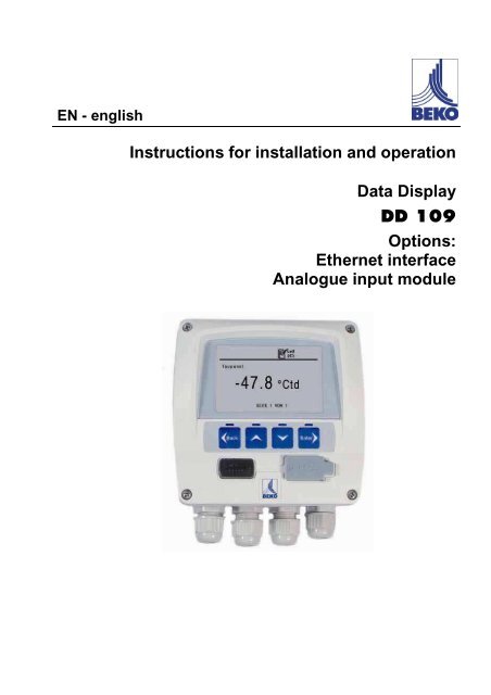
EN - english<strong>Instructions</strong> <strong>for</strong> <strong>installation</strong> <strong>and</strong> <strong>operation</strong><strong>Data</strong> <strong>Display</strong><strong>DD</strong> <strong>109</strong>Options:Ethernet interfaceAnalogue input module
Contents1 Safety instructions..................................................................................................................................52 Field of application .................................................................................................................................63 Functions of the data display unit...........................................................................................................64 <strong>Data</strong> display with sensors ......................................................................................................................65 Technical data <strong>DD</strong> <strong>109</strong>...........................................................................................................................76 Technical data analogue input module ..................................................................................................87 Dimensions.............................................................................................................................................98 Installation ............................................................................................................................................<strong>109</strong> Connectors on the rear ........................................................................................................................1110 Connector assignment rear..................................................................................................................1111 Connection diagrams ...........................................................................................................................1211.1 Voltage supply......................................................................................................................................1211.2 Alarm connection..................................................................................................................................1212 Connection flow sensor........................................................................................................................1312.1 Connection of a flow sensor to the data display unit............................................................................1312.2 Connection of two flow sensors to the data display unit ......................................................................1413 Connection DP sensor .........................................................................................................................1513.1 Connection of a dew point sensor to the data display unit ..................................................................1513.2 Connection of two dew point sensors to the data display unit .............................................................1514 Utilisation 4-20mA st<strong>and</strong>ard signal.......................................................................................................1614.1 Analogue current signal flow sensor FS <strong>109</strong> .......................................................................................1614.2 Analogue current signal DP <strong>109</strong> dew point measuring device ............................................................1615 Galvanically separated pulse output ....................................................................................................1615.1 Connection diagram pulse output flow sensor .....................................................................................1716 Connection pulse: active high ..............................................................................................................1716.1 Connection pulse: active low................................................................................................................1717 Analogue input module connections E <strong>and</strong> F (optional) ......................................................................1817.1 Legend analogue inputs connection E + F...........................................................................................1817.2 Thermocouple NiCr-Ni type K <strong>for</strong> connection E <strong>and</strong> F.........................................................................1917.3 Pt100/ Pt1000 connection to E <strong>and</strong> F ..................................................................................................1917.4 Sensors with voltage outputs 0… 1/ 10 VDC with <strong>and</strong> without voltage supply via <strong>DD</strong> <strong>109</strong>................2017.4.1 External voltage supply........................................................................................................................2017.4.2 With voltage supply via <strong>DD</strong> <strong>109</strong> ...........................................................................................................2017.5 Sensors with power output in two-wire technology with internal voltage supply <strong>DD</strong> <strong>109</strong>,e.g. pressure sensors 4… 20 mA in two-wire technology....................................................................2117.6 Sensors with 0/4… 20 mA <strong>and</strong> external voltage supply ......................................................................2117.7 Sensors with 0/4… 20 mA <strong>and</strong> voltage supply via <strong>DD</strong> <strong>109</strong> .................................................................2217.8 Sensors with 4… 20 mA, two-wire technology,supply via <strong>DD</strong> <strong>109</strong> <strong>and</strong> additional external display unit........................................................................2217.9 Sensors with a 4… 20 mA signal,external voltage supply <strong>and</strong> additional external display unit................................................................2317.10 Sensors with a 4… 20 mA signal<strong>and</strong> voltage supply via <strong>DD</strong> <strong>109</strong> <strong>and</strong> additional external display unit....................................................2318 Connection Ethernet interface (optional) .............................................................................................2418.1 Installation bend protection ..................................................................................................................2418.2 Select the protocol in the <strong>DD</strong> <strong>109</strong> ........................................................................................................2419 Operation..............................................................................................................................................26<strong>Data</strong> display unit <strong>DD</strong><strong>109</strong> 3
Safety instructions19.1 Description of the display symbols.......................................................................................................2619.1.1 Description of the status symbols ........................................................................................................2619.2 Operation of the main keys ..................................................................................................................2719.2.1 Concept <strong>for</strong> the key <strong>operation</strong>..............................................................................................................2719.3 Typical menu display............................................................................................................................2819.3.1 Choice boxes........................................................................................................................................2819.3.2 Numeric settings...................................................................................................................................2819.4 In<strong>for</strong>mation subsequent to the activation of the device........................................................................2919.5 Main menu items..................................................................................................................................3019.5.1 Logger <strong>operation</strong> ..................................................................................................................................3019.5.2 Overview operating menu ....................................................................................................................3119.5.3 Alarm settings.......................................................................................................................................3219.5.4 Sensor settings.....................................................................................................................................3219.5.5 Inner diameter of the pipe ....................................................................................................................3219.5.6 System status <strong>and</strong> settings ..................................................................................................................3320 Scope of delivery..................................................................................................................................3321 Declaration of con<strong>for</strong>mity .....................................................................................................................3422 Appendix industrial data transfer..........................................................................................................3622.1 General requirements ..........................................................................................................................3622.1.1 Hardware requirements........................................................................................................................3622.1.2 Application software .............................................................................................................................3622.2 Installation of the SW <strong>109</strong> software......................................................................................................3722.2.1 Ethernet <strong>and</strong> SW <strong>109</strong>...........................................................................................................................374 <strong>Data</strong> display unit <strong>DD</strong><strong>109</strong>
Safety instructions1 Safety instructionsPlease check whether or not these instructions correspond to the device type.Please adhere to all advice given in these operating instructions. They include basicin<strong>for</strong>mation which needs to be observed during <strong>installation</strong>, <strong>operation</strong> <strong>and</strong> maintenance.There<strong>for</strong>e, it is vital <strong>for</strong> the technician <strong>and</strong> the responsible operator /skilled personnel to readthese operating instructions prior to <strong>installation</strong>, start-up <strong>and</strong> maintenance.The operating instructions must be accessible at all times at the place of application of the datadisplay unit.In addition to these instructions, local <strong>and</strong> national regulations need to be observed, if required.If you have any queries regarding these instructions or the device, please contact BEKOTECHNOLOGIES.Measures:Danger!Supply voltage!There is the risk of an electric shock involving injury or death when coming into contactwith non-insulated components carrying supply voltage.• During electric <strong>installation</strong>s, all regulations in <strong>for</strong>ce need to be adhered to (e.g. VDE 0100).• Service measures must only be undertaken when the system is deactivated!• All types of electrical work must be carried out by authorised <strong>and</strong> qualified personnel only .Measures:Danger!Inadmissible operating parameters!Under-running or exceeding the limit values involves risks <strong>for</strong> persons <strong>and</strong> the material<strong>and</strong> malfunction <strong>and</strong> service failures may occur.• Make sure that the data display unit is operated only within the permissible limit values indicated on thetype plate.• Exact compliance with the per<strong>for</strong>mance data of the data display unit in connection with the case ofapplication.• Do not exceed the permissible storage <strong>and</strong> transport temperature. Further safety instructions :• During <strong>installation</strong> <strong>and</strong> <strong>operation</strong>, the national regulations <strong>and</strong> safety instructions in <strong>for</strong>ce also need tobe observed.• The data display unit must not be employed in hazardous areas.Additional instructions:• Do not overheat the device!Caution!Malfunction of the data display unitIncorrect <strong>installation</strong> <strong>and</strong> insufficient maintenance can lead to malfunctions with thedata display unit <strong>and</strong> may compromise the indication or result in misinterpretations.<strong>Data</strong> display unit <strong>DD</strong><strong>109</strong> 5
Field of application2 Field of application• The data display unit is a stationary indicating device with data logger <strong>for</strong> respective consumption <strong>and</strong>dew point sensors, <strong>for</strong> example (see "Technical data").• The data display unit is used in the following applications, <strong>for</strong> example• Flow measuring stations• Dew point set• To work properly, the data display unit requires supply voltage (see "Technical data").• The data display unit is not suitable <strong>for</strong> use in hazardous areas.3 Functions of the data display unit• Graphic display <strong>for</strong> a simple user interface• Flexible voltage supply: 100… 240 VAC/ 50… 60Hz• Two inputs <strong>for</strong> BEKO consumption <strong>and</strong> dew point sensors• 4… 20 mA outputs <strong>for</strong> further processing• Two relay outputs <strong>for</strong> alarms• USB interface• Housing mountable on the wall or in the equipment cabinet• <strong>Data</strong> logger function <strong>for</strong> 1,000,000 values• Optional: Ethernet module <strong>and</strong> analogue input module4 <strong>Data</strong> display with sensorsBEKO consumption sensorBEKO dew point sensorTwo analogue sensorsEthernet output (optional)Alarm output4… 20 mA output <strong>for</strong> furtherprocessingUSB interface6 <strong>Data</strong> display unit <strong>DD</strong><strong>109</strong>
Technical data <strong>DD</strong> <strong>109</strong>5 Technical data <strong>DD</strong> <strong>109</strong>Dimensions wall housing 118mm x 115mm x 93mm = 4.65“ x 4.53“ x 3.66“Dimensionsequipment cabinet <strong>installation</strong>Housing material92mm x 92mm = 3.62“ x 3.62“ABS plasticsProtection class housing IP 65Operating temperature 0… 50°C = 0... 122°FTransport temperature -20… 70 °C = -4... 158 °FSensor inputsInterfaceKeypadVoltage supply<strong>Display</strong>SettingsAlarm outputAnalogue output<strong>Data</strong> loggerSoftwareTwo inputs <strong>for</strong> dew point <strong>and</strong> consumption probes(optional: two analogue inputs)USBFour keys100 .… 240 VAC / 50-60 Hz / 10 VAGraphic display, 160 x 100 pixelsThe data display unit is supplied with st<strong>and</strong>ard settingsTwo relays, 230 VAC, 3 A, potential-free, two-way contactConnection of the 4… 20 mA signals of the dew point <strong>and</strong> consumptionsensors (max. load ≤ 500 Ω)• Up to 1,000,000 values• Start-up time programmable or manually adjustable• Logging interval, min. 1 sec, max. 59 min. 59 sec• Storage of the average valueDelivery settings:Logging interval 10 sCircular buffer<strong>Data</strong> storage starts as soon as the device is started upThe SW <strong>109</strong> BEKO software is optionally available, with which allsettings at the <strong>DD</strong> <strong>109</strong> can be configured <strong>and</strong> the logger data read out.Configuration of sensors/of the <strong>DD</strong> <strong>109</strong> display unit.When the <strong>DD</strong> <strong>109</strong> display unit is purchased in a set with a dew point or volume flow sensor, the<strong>DD</strong> <strong>109</strong> display unit is pre-configured. When the <strong>DD</strong> <strong>109</strong> is delivered without sensors,configuration is imperative.If you wish to connect further sensors or modify the configuration of the display unit, you needthe corresponding CONFIGURATION software. This software is a constituent part of theoptional SW <strong>109</strong> software.The CONFIGURATION software is also available <strong>for</strong> download free of charge at www.beko.de.In this case, you will need an additional USB cable with A-plugs at both ends.<strong>Data</strong> display unit <strong>DD</strong><strong>109</strong> 7
Technical data analogue input module6 Technical data analogue input moduleInput signalsSignal current(0…20mA/4…20mA)internal or externalvoltage supplyMeasuring range 0…20 mAResolution0,0001 mAAccuracy ± 0,003 mA ± 0,05 %Signal voltage(0…1V)Input resistanceMeasuring rangeResolution50 Ω0…1 V0,05 mVAccuracy ± 0,2 mV ± 0,05 %Signal voltage(0…10V)Input resistanceMeasuring rangeResolution10 MΩ0…10 V0,5 mVAccuracy ± 2 mV ± 0,05 %Input resistance10 MΩRTDPt100Measuring range -200…900 °CResolution 0,1 °CAccuracy ± 0,2 °CRTDPt1000Measuring range -200…900 °CResolution 0,1 °CAccuracy ± 0,2 °CThermocouple K Measuring range -270…1372 °CThermocouple J Measuring range -210…1200 °CThermocouple T Measuring range -265…400 °CThermocouple E Measuring range -200…1000 °CResolution 0,1 °CAccuracy ± 0,5 °C ± 0,05 %Input resistance10 MΩSupply <strong>for</strong> externalsensorsFor two externalsensors24 V / max. 25 mAeachConfiguration of sensors/of the <strong>DD</strong> <strong>109</strong> display unit.When the <strong>DD</strong> <strong>109</strong> display unit is purchased in a set with a dew point or volume flow sensor, the<strong>DD</strong> <strong>109</strong> display unit is pre-configured. When the <strong>DD</strong> <strong>109</strong> is delivered without sensors,configuration is imperative.If you wish to connect further sensors or modify the configuration of the display unit, you needthe corresponding CONFIGURATION software. This software is a constituent part of theoptional SW <strong>109</strong> software.The CONFIGURATION software is also available <strong>for</strong> download free of charge at www.beko.de.In this case, you will need an additional USB cable with A-plugs at both ends.8 <strong>Data</strong> display unit <strong>DD</strong><strong>109</strong>
7 DimensionsDimensionsDimensionsWall housingDimensions <strong>for</strong> theequipment cabinet<strong>installation</strong><strong>Data</strong> display unit <strong>DD</strong><strong>109</strong> 9
Installation8 InstallationMounting wall housing:Delivery as a set with sensors:The cables <strong>for</strong> the sensors <strong>and</strong> <strong>for</strong> the voltagesupply are already wired at the <strong>DD</strong> <strong>109</strong>:• Do not connect the power cord with the net• Unscrew the four screws at the front housing• Pull off the plug on the back of the fronthousing• Drill holes in the wall according to the specifiedraster size (see sketch)• Mount the wall housing (dowels <strong>and</strong> screwsincluded in the scope of delivery)• Re-mount the plug <strong>for</strong> the voltage supply <strong>and</strong> <strong>for</strong>the sensors• Insert the front housing in the wall housing<strong>and</strong> tighten the four screwsDelivery display unit <strong>DD</strong> <strong>109</strong> (separate):The cables <strong>for</strong> the sensors <strong>and</strong> <strong>for</strong> the voltagesupply are not wired at the <strong>DD</strong> <strong>109</strong>:• Unscrew the four screws at the front housing• Drill holes in the wall according to the specifiedraster size (3 x, see sketch)• Mount the wall housing (dowels <strong>and</strong> screwsincluded in the scope of delivery)• Wiring of the voltage supply <strong>and</strong> of the sensor(s)in accordance with the following instructions• Insert the front part of the housing into the wallhousing<strong>and</strong> tighten the four screws•Tighten the compression fitting of the cablesInstallation in the equipment cabinet• Cavity92 mm (+0.8, -0.0) x 92 mm (+0.8, -0.0)Max. sheet thickness 8 mm (see sketch above)• For the <strong>installation</strong> in the equipment cabinet,insert the front housinginto the correspondingly prepared cavity.• Insert the mounting clips <strong>and</strong> clamp the housingbyturning the treerods• Wiring of the voltage supply <strong>and</strong> of thesensor(s) in accordance with the followinginstructions10 <strong>Data</strong> display unit <strong>DD</strong><strong>109</strong>
9 Connectors on the rearConnectors on the rearSupply:AWG12 – AWG24, line cross-sections: 0.2 ... 2.5 mm 2Signals:AWG16 ... AWG28, line cross-sections: 0.14 ... 1.5 mm 210 Connector assignment rearConnector assignment on the rear of thedata display unit:A: Alarm 1B: Alarm 2C: Voltage supplyD: No useE: Optional (analogue input module)F: Optional (analogue input module)G: Flow sensorH: Galvanically separated pulse outputFlow sensorI: DP sensorConfiguration of sensors/of the <strong>DD</strong> <strong>109</strong> display unit.When the <strong>DD</strong> <strong>109</strong> display unit is purchased in a set with a dew point or volume flow sensor, the<strong>DD</strong> <strong>109</strong> display unit is pre-configured. When the <strong>DD</strong> <strong>109</strong> is delivered without sensors,configuration is imperative.If you wish to connect further sensors or modify the configuration of the display unit, you needthe corresponding CONFIGURATION software. This software is a constituent part of theoptional SW <strong>109</strong> software.The CONFIGURATION software is also available <strong>for</strong> download free of charge at www.beko.de.In this case, you will need an additional USB cable with A-plugs at both ends.<strong>Data</strong> display unit <strong>DD</strong><strong>109</strong> 11
Connection diagrams11 Connection diagrams11.1 Voltage supplyMeasures:Danger!Supply voltage!There is the risk of an electric shock involving injury or death when coming into contactwith non-insulated components carrying supply voltage.• During electric <strong>installation</strong>s, all regulations in <strong>for</strong>ce need to be adhered to (e.g. VDE 0100).• Installation <strong>and</strong> service measures must only be undertaken when the system is deactivated!• All types of electrical work must be carried out by authorised <strong>and</strong> qualified personnel only .100-240 VAC, 50-60 Hz11.2 Alarm connectionNC <strong>and</strong> COM are closed in the event of:- Alarm- Voltage failure- Sensor break12 <strong>Data</strong> display unit <strong>DD</strong><strong>109</strong>
Connection flow sensor12 Connection flow sensorStart-up volume flow sensorFor the start-up of a volume flow sensor, it is imperative to adjust the corresponding innerdiameter of the pipe.This setting can be effected via the menu of the <strong>DD</strong> <strong>109</strong> data display unit.For this, please refer to Chapter 19 "Operation".12.1 Connection of a flow sensor to the data display unitFlow sensorConnector "G"Analogue output connector "G"Pulse counter:Connector "H"<strong>Data</strong> display unit <strong>DD</strong><strong>109</strong> 13
Connection flow sensor12.2 Connection of two flow sensors to the data display unitFlow sensor 1Connector "G"Analogue output connector "G“Pulse counter:Connector "H"Flow sensor 2Connectors "I" <strong>and</strong> "H"Analogue output connector "I“ <strong>and</strong>"H"Pulse counter:Connector "H"Configuration of sensors/of the <strong>DD</strong> <strong>109</strong> display unit.When the <strong>DD</strong> <strong>109</strong> display unit is purchased in a set with a dew point or volume flow sensor, the<strong>DD</strong> <strong>109</strong> display unit is pre-configured. When the <strong>DD</strong> <strong>109</strong> is delivered without sensors,configuration is imperative.If you wish to connect further sensors or modify the configuration of the display unit, you needthe corresponding CONFIGURATION software. This software is a constituent part of theoptional SW <strong>109</strong> software.The CONFIGURATION software is also available <strong>for</strong> download free of charge at www.beko.de.In this case, you will need an additional USB cable with A-plugs at both ends.14 <strong>Data</strong> display unit <strong>DD</strong><strong>109</strong>
Connection DP sensor13 Connection DP sensor13.1 Connection of a dew point sensor to the data display unitDew point sensor 1Connector "I"Analogue output connector "I"13.2 Connection of two dew point sensors to the data display unitDew point sensor 1Connector "I"Analogue output connector "I"Dew point sensor 2Connector "G"Analogue output connector "G"Configuration of sensors/of the <strong>DD</strong> <strong>109</strong> display unit.When the <strong>DD</strong> <strong>109</strong> display unit is purchased in a set with a dew point or volume flow sensor, the<strong>DD</strong> <strong>109</strong> display unit is pre-configured. When the <strong>DD</strong> <strong>109</strong> is delivered without sensors,configuration is imperative.If you wish to connect further sensors or modify the configuration of the display unit, you needthe corresponding CONFIGURATION software. This software is a constituent part of theoptional SW <strong>109</strong> software.The CONFIGURATION software is also available <strong>for</strong> download free of charge at www.beko.de.In this case, you will need an additional USB cable with A-plugs at both ends.<strong>Data</strong> display unit <strong>DD</strong><strong>109</strong> 15
Utilisation 4-20mA st<strong>and</strong>ard signal14 Utilisation 4-20mA st<strong>and</strong>ard signalWith the FS <strong>109</strong> flow sensor <strong>and</strong> the DP <strong>109</strong> dew point measuring device, there is the possibility to providethe measured values as an analogue electric signal 4...20 mA <strong>for</strong> further processing. In the connectiondiagrams, this collection of the current signal is already indicated.14.1 Analogue current signal flow sensor FS <strong>109</strong>Connector G "flow sensor"The flow sensor is connected to theterminals of connector G in accordance withthe wiring shown on the left side. Theanalogue signal (4...20mA) is applied toterminals 1 <strong>and</strong> 3 <strong>and</strong> can be tapped ifrequired (max. load ≤ 500 Ω).14.2 Analogue current signal DP <strong>109</strong> dew point measuring deviceConnector I "Dew point measuring device"The dew point measuring device isconnected to the terminals of connector I inaccordance with the wiring shown on theleft side. The analogue signal (4...20mA) isapplied to terminals 1 <strong>and</strong> 2 <strong>and</strong> can betapped if required.(max. load ≤ 500 Ω).In the event that the analogue signal is notused, it is imperative to use a wire jumperhere (already installed by themanufacturer).15 Galvanically separated pulse outputA galvanically separated pulse output is available <strong>for</strong> the flow sensor, a semi-conductor relay which isgalvanically separated from the supply voltage of the flow probes by means of an optocoupler.Max. switching capacity : Umax: 32V, Imax: 20 mA16 <strong>Data</strong> display unit <strong>DD</strong><strong>109</strong>
Connection pulse: active high15.1 Connection diagram pulse output flow sensorPulse counter Flow sensor toconnector H terminals 1 <strong>and</strong> 216 Connection pulse: active highActive high16.1 Connection pulse: active lowActive low<strong>Data</strong> display unit <strong>DD</strong><strong>109</strong> 17
Analogue input module connections E <strong>and</strong> F (optional)17 Analogue input module connections E <strong>and</strong> F (optional)The E <strong>and</strong> F connectors have an identical terminal assignment <strong>for</strong> analogue sensors 0…1/10 V, 0/4…20 mA,thermocouple, Pt100/ Pt1000.Configuration of sensors / of the <strong>DD</strong> <strong>109</strong> display unit.If you wish to connect analogue sensors or modify the configuration of the display unit, youneed the corresponding CONFIGURATION software. This software is a constituent part of theoptional SW <strong>109</strong> software.The CONFIGURATION software is also available <strong>for</strong> download free of charge at www.beko.de.In this case, you will need an additional USB cable with A-plugs at both ends.17.1 Legend analogue inputs connection E + FE1 I-Ptxxx+2 S+3 S-4 I-Ptxxx-5 20 mA+6 I-loop+7 I-loop-8 V-9 V+F1 I-Ptxxx+2 S+3 S-4 I-Ptxxx-5 20 mA6 I-loop+7 I-loop-8 GND9 V+18 <strong>Data</strong> display unit <strong>DD</strong><strong>109</strong>
Analogue input module connections E <strong>and</strong> F (optional)17.2 Thermocouple NiCr-Ni type K <strong>for</strong> connection E <strong>and</strong> F1 /2 Connection + thermocouple3 Connection - thermocouple4 /5 /6 /7 /8 /17.3 Pt100/ Pt1000 connection to E <strong>and</strong> F1 I-Ptxxx+ / 3-wire2 Pt100/ Pt1000 +3 Pt100/ Pt1000 +4 I-Ptxxx5 /6 /7 /8 /<strong>Data</strong> display unit <strong>DD</strong><strong>109</strong> 19
Analogue input module connections E <strong>and</strong> F (optional)17.4 Sensors with voltage outputs 0… 1/ 10 VDCwith <strong>and</strong> without voltage supply via <strong>DD</strong> <strong>109</strong>17.4.1 External voltage supply1 /2 Signal + (0… 1/ 10 V)3 Signal – (0… 1/ 10 V)45 /6 /7 /8 Voltage supply 0 V9 Voltage supply 24 V DC17.4.2 With voltage supply via <strong>DD</strong> <strong>109</strong>20 <strong>Data</strong> display unit <strong>DD</strong><strong>109</strong>
Analogue input module connections E <strong>and</strong> F (optional)17.5 Sensors with power output in two-wire technology with internal voltage supply <strong>DD</strong> <strong>109</strong>,e.g. pressure sensors 4… 20 mA in two-wire technology1 /2 /3 Current signal4 /5 Current signal6 /7 /8 Voltage supply 0 V9 Voltage supply 24 V DC17.6 Sensors with 0/4… 20 mA <strong>and</strong> external voltage supply1 /2 /3 Current signal4 /5 Current signal6 /7 /8 /9 /<strong>Data</strong> display unit <strong>DD</strong><strong>109</strong> 21
Analogue input module connections E <strong>and</strong> F (optional)17.7 Sensors with 0/4… 20 mA <strong>and</strong> voltage supply via <strong>DD</strong> <strong>109</strong>1 /2 /3 Current signal – (0/4,,, 20 mA)4 /5 Current signal +(0/4,,, 20 mA)6 /7 /8 Voltage supply <strong>for</strong> sensor 0 V9 Voltage supply <strong>for</strong> sensor24 V DC17.8 Sensors with 4… 20 mA, two-wire technology, supply via <strong>DD</strong> <strong>109</strong><strong>and</strong> additional external display unit1 /2 /3 Current signal –4 /5 Current signal +6 Current signal7 Current signal8 Voltage supply 0 V9 Voltage supply 24 V DC22 <strong>Data</strong> display unit <strong>DD</strong><strong>109</strong>
Analogue input module connections E <strong>and</strong> F (optional)17.9 Sensors with a 4… 20 mA signal, external voltage supply<strong>and</strong> additional external display unit1 /2 /3 Current signal –4 /5 Current signal +6 Current signal7 Current signal8 /9 /17.10 Sensors with a 4… 20 mA signal <strong>and</strong> voltage supply via <strong>DD</strong> <strong>109</strong><strong>and</strong> additional external display unit1 /2 /3 Current signal –4 /5 Current signal +6 Current signal7 Current signal8 Voltage supply 0 V9 Voltage supply 24 V DC<strong>Data</strong> display unit <strong>DD</strong><strong>109</strong> 23
Connection Ethernet interface (optional)18 Connection Ethernet interface (optional)The <strong>DD</strong> <strong>109</strong> is connected via a st<strong>and</strong>ard Ethernet RJ45 plug.For the <strong>installation</strong> in the equipment cabinet or as a wall housing, the <strong>DD</strong> <strong>109</strong> can be directly connected withthe Ethernet RJ45 plug (wall housing IP65).Internal RJ45 interfaceExternal RJ45 interface (IP65)18.1 Installation bend protection1. Pull the bend protection jacket over the cable2. Plug the Ethernet RJ45 plug into the socket3. Mount the bend protection jacket18.2 Select the protocol in the <strong>DD</strong> <strong>109</strong>The <strong>DD</strong> <strong>109</strong> supports different protocols - CS bus or MODBUS - which can be selected via the comm<strong>and</strong>menu in the <strong>DD</strong> <strong>109</strong>. The SW <strong>109</strong> software operates with the CS bus protocol.For the integration into customer-owned systems, the MODBUS protocol can be used.In such a case, please request the protocol description of MODBUS from BEKO.Please proceed as follows should you wish to change the protocol:1. Press [ Enter ] in the display mode to access the menu mode.2. Select the "Communication setting" with the buttons <strong>and</strong> confirm with [ Enter ]3. Menu "Select protocol", confirm with [ Enter ]4. Select "CS BUS protocol" with [ Enter ]5. Press the [ Back ] button several times to return to the display mode24 <strong>Data</strong> display unit <strong>DD</strong><strong>109</strong>
Connection Ethernet interface (optional)Change of the IP address.The Ethernet expansion is automatically set to DHCP (automatic reception of the IP address).In the event that you should wish to change the IP address manually, you will need specialsoftware. BEKO will be glad to provide you with this software or to effect the settings <strong>for</strong> you.In this case, please contact the BEKO service via www.beko.de.<strong>Data</strong> display unit <strong>DD</strong><strong>109</strong> 25
Operation19 OperationThe display of measured values is implemented pagewise. Depending on the sensor <strong>and</strong> setting, one ormore values can be shown per display page. These settings can be changed via the optional SW <strong>109</strong>software, the CONFIGURATION software free of charge, or, upon request, through BEKOTECHNOLOGIES.Configuration of sensors / of the <strong>DD</strong> <strong>109</strong> display unit.When the <strong>DD</strong> <strong>109</strong> display unit is purchased in a set with a dew point or volume flow sensor, the<strong>DD</strong> <strong>109</strong> display unit is pre-configured. When the <strong>DD</strong> <strong>109</strong> is delivered without sensors,configuration is imperative.If you wish to connect further sensors or modify the configuration of the display unit, you needthe corresponding CONFIGURATION software. This software is a constituent part of theoptional SW <strong>109</strong> software.The CONFIGURATION software is also available <strong>for</strong> download free of charge at www.beko.de.In this case, you will need an additional USB cable with A-plugs at both ends.19.1 Description of the display symbolsStatus display<strong>Display</strong> of measured values:Only one page with measured values is displayed at one time.The user can page through all available pages via the "Arrow-up" or"Arrow-down" buttons.Page display:The current page number of the measured values <strong>and</strong> the total numberof pages is displayed.19.1.1 Description of the status symbolsThese symbols show the system status.Explanation of the symbols in detail:USB connection symbol:The data display unit is connected to a PC via USBAlarm status symbol: alarm 1 (pre-alarm)Alarm 1 is exceededAlarm status symbol: alarm 1 (pre-alarm)Alarm 1 not reached26 <strong>Data</strong> display unit <strong>DD</strong><strong>109</strong>
OperationAlarm status symbol: alarm 2 (main alarm)Alarm 2 is exceededAlarm status symbol: alarm 2 (main alarm)Alarm 2 is not reachedLogger module status:WAIT: Time <strong>and</strong> start conditions are being set, waiting <strong>for</strong>start of recordingLOG: Logger module is recording dataSTOP: Recording finishedDEL: Logger is deleting protocol dataERR: Error during data recordingLOG 100%: Free memory of the logger module in per centCYCLE: Logger memory functions in cyclic <strong>operation</strong>19.2 Operation of the main keys19.2.1 Concept <strong>for</strong> the key <strong>operation</strong>or• Scan through different menu items <strong>and</strong> page through thepages with measured data• Adjust or modify setting options <strong>and</strong> numberings.• Leave the current menu item• Leave the setting mode without saving modifications• Change to the submenu or to the next menu level of the currentlyselected menu item• Confirm setting modifications<strong>Data</strong> display unit <strong>DD</strong><strong>109</strong> 27
Operation19.3 Typical menu display• The selected menu item is shadowed with a dark colour• A ">" on the right side indicates that the menu can be left or that you canchange to the next menu level• A "
Operation19.4 In<strong>for</strong>mation subsequent to the activation of the deviceSubsequent to the activation of the data display unit, systemin<strong>for</strong>mation is displayed <strong>for</strong> approximately five seconds.The system in<strong>for</strong>mation is helpful <strong>for</strong> service questions, to ascertain,<strong>for</strong> example, the version no. <strong>and</strong> the firmware version.The system in<strong>for</strong>mation can be re-invoked at all times in the"System info" menu item.When the sensing heads are connected in accordance with theconfiguration, the data display unit will automatically recognisethese <strong>and</strong> start to display real-time values received from thesensors.Measured values are probably indicated on more than one page. Toshow a further page, simply pressthe "Arrow up" or the "Arrow down"button.<strong>Data</strong> display unit <strong>DD</strong><strong>109</strong> 29
Operation19.5 Main menu itemsThe data display unit is delivered with st<strong>and</strong>ard settings.Main menu items in the data display unit:• Logger <strong>operation</strong>• Setting alarm 1• Setting alarm 2• Sensor setting• Communication settings (option bus systems)• System status <strong>and</strong> setting19.5.1 Logger <strong>operation</strong>Measuring rateSetting storage interval <strong>and</strong> average determinationThe storage interval defines the time interval, in which the data will be stored. Avalue is recorded from every activated channel. The option "averagedetermination" can be used to calculate the mean value, meaning that the datadisplay unit measures every second, <strong>and</strong> when the storage interval is 10seconds, the average will be determined on the basis of the last 10 values <strong>and</strong>stored as a measured value.Manual startStart/Stop recordingStarts or stops data recording. A new file is created in the memory each time anew recording takes place.Time startTime setting, trigger conditionThe data display unit can be adjusted in such a manner that it will start themeasurement at a defined time.Memory statusIndication memoryIndicates the status <strong>and</strong> the size of available memory.<strong>Display</strong> protocolsIndividual protocols (files) or the entire memory can be displayed <strong>and</strong> deleted, ifrequired. The data display unit shows the available protocols with the date,number of channels, number of recorded values per channel <strong>and</strong> the min./max.<strong>and</strong> average values.Delete protocolsDeletes selected protocols.Format memoryDeletes the internal memory.30 <strong>Data</strong> display unit <strong>DD</strong><strong>109</strong>
Operation19.5.2 Overview operating menuLogger <strong>operation</strong>Setting limit value alarm1Setting limit value alarm 2Sensor settingTerminal I:Dew pointTerminal G:ConsumptionSet unit°C td (°F td)Set reference pressure mg/m³g/m³g/kgSet inner diameter of the pipeMeasuring rateManual startstopMemory statusTime start<strong>DD</strong> MM YYYYhh:mm:ss<strong>Display</strong> protocolDelete protocolFormat memoryMeter <strong>for</strong> total consumptionVolume flow unit (mass flowunit)Consumption unitMeasuring unitFlowlm³cfkgm³/hm³/minl/minl/scfmkg/skg/minkg/hVolume flowSet reference pressureSet reference temperatureScaling analogue outputSet type of gasAirCO 2N 2ON 2ArgonTerminal E/F:Communication settings<strong>Display</strong> settings<strong>Display</strong> settings <strong>and</strong> statusSelect protocolConfigure communication settingsSet salve addressSystem status <strong>and</strong> settingsCS BusModbusModbus/TCPModbus over TCPTime/dateSystem statusLCD contrastSystem reset<strong>Data</strong> display unit <strong>DD</strong><strong>109</strong> 31
Operation19.5.3 Alarm settingsTwo alarm limit values can be set individually:1. "Setting limit value alarm 1"2. "Setting limit value Alarm 2"In this example, the sensor is connected to terminal I."Type: alarm when exceeding the limit" means:the alarm ist activated when the value is higher than the limit value.In the event of an alarm as a result of upper/lower limit violation thebacklighting is red or flashes.Hysteresis is set to 2.00 °C td in the factory.Please note that these settings cannot be modified directly at thedata display unit.Please contact BEKO TECHNOLOGIES GMBH19.5.4 Sensor settingsSensor settings <strong>for</strong> our consumption or dew point sensors are stored in the senor itself. The data display unitcan be used to modify such settings. For this purpose, select the menu function "Sensor settings".The available menu items are shown on the display: terminal I: dewpointTerminal G: consumptionSelect the desired input mask to configure your sensor settings.When delivering a data display/sensor unit, the settings areadjusted to one another. Please check the configuration <strong>for</strong>compliance with the setting in the sensor be<strong>for</strong>e connecting newsensors.19.5.5 Inner diameter of the pipeSensor InnendurchmessereinstellenThe inner diameter of the pipe is also set via the "consumption"menu item. The <strong>DD</strong> <strong>109</strong> data display unit automatically scales theanalogue output 4 ... 20 mA to the respective values.It is imperative to effect this setting when starting up a volume flowsensor.32 <strong>Data</strong> display unit <strong>DD</strong><strong>109</strong>
Scope of delivery19.5.6 System status <strong>and</strong> settingsSetting time/dateSetting the internal clock.<strong>Display</strong> system statusImportant in<strong>for</strong>mation <strong>for</strong> service inquiries.Changing the LCD contrastThe contrast of the display can be modified.System resetIt is recommended to use this function when other sensors areconnected, to update the system settings.20 Scope of delivery• <strong>Data</strong> display unit in a wall housing in accordance with your order• Mounting clips <strong>for</strong> the <strong>installation</strong> in the equipment cabinet• Operating instructions<strong>Data</strong> display unit <strong>DD</strong><strong>109</strong> 33
Declaration of con<strong>for</strong>mity21 Declaration of con<strong>for</strong>mity34 <strong>Data</strong> display unit <strong>DD</strong><strong>109</strong>
Declaration of con<strong>for</strong>mityBEKO TECHNOLOGIES GMBH41468 Neuss, GERMANYPhone: +49 2131 988-0www.beko.deEC Declaration of Con<strong>for</strong>mityWe hereby declare that the products indicated hereafter, in the delivered per<strong>for</strong>mance, comply with thestipulations of the relevant st<strong>and</strong>ards:Product designation: <strong>DD</strong> <strong>109</strong>in the versions:Voltage supply:Product description <strong>and</strong> function:St<strong>and</strong>ardInterface analogue input Interface Ethernet100 – 240 VAC / 50-60 Hz / 10 VA<strong>Data</strong> display <strong>for</strong> the recording <strong>and</strong> indication ofmeasured dataLow-Voltage Directive 2006/95/ECHarmonized st<strong>and</strong>ards applied:Year of CE labelling: 09DIN EN 61010-1: 2002-08 + DIN EN 61010-1/ Amend.1:2002-11 + DIN EN 61010-1/Amend.2: 2004-01EMC Directive 2004/108/ECSt<strong>and</strong>ards applied:Emitted interference:DIN EN 61326-1: 2006-10 +DIN EN 61326-1/Amend.1:2008-06 + DIN EN 61326-1/Amend.2: 2011-04 + DINEN 61000-3-2: 2006-10Immunity to interference:DIN EN 61326-1: 2006-10 +DIN EN 61326-1/ Amend.1:2008-06 + DIN EN 61326-1/Amend.2: 2011-04The products are labelled with the sign shown below:This declaration only refers to products in the condition in which they have been placed into circulation. Partswhich have not been installed by the manufacturer <strong>and</strong> / or modifications which have been implementedsubsequently remain unconsidered.Neuss, 14 December 2011BEKO TECHNOLOGIES GMBHp.p. Christian RiedelHead of Quality Department<strong>Data</strong> display unit <strong>DD</strong><strong>109</strong> 35
Appendix industrial data transfer22 Appendix industrial data transferThe <strong>DD</strong> <strong>109</strong> multi measuring device can be directly connected to an Ethernet network (switch / router /HUB).22.1 General requirements22.1.1 Hardware requirements<strong>DD</strong> <strong>109</strong> with Ethernet interfaceSt<strong>and</strong>ard RJ45 Ethernet cable, max. length 100 m<strong>DD</strong> <strong>109</strong> connected via RJ45 to a LAN (Local Area Network) with DHCP serverPC with SW <strong>109</strong> software, PC with Ethernet interface22.1.2 Application softwareSW <strong>109</strong>• BEKO SW <strong>109</strong> can communicate with a selected <strong>DD</strong> <strong>109</strong> via Ethernet.• All <strong>DD</strong> <strong>109</strong>s available on the network are shown in a list <strong>and</strong> are individually selectable• Online measurement of all connected <strong>DD</strong> <strong>109</strong>s - successively• <strong>Data</strong> storage via PC• <strong>Data</strong> logger of the selected <strong>DD</strong> <strong>109</strong> online operable• Graphic data evaluation36 <strong>Data</strong> display unit <strong>DD</strong><strong>109</strong>
Appendix industrial data transfer22.2 Installation of the SW <strong>109</strong> software22.2.1 Ethernet <strong>and</strong> SW <strong>109</strong>The SW <strong>109</strong> software is installed on the computer.An <strong>installation</strong> menu will lead the user through the <strong>installation</strong> process. Drivers are installed automatically.Language settings are automatically adopted by the PC.The software needs to be registered within 45 days.Subsequent to the software <strong>installation</strong>, please connect the <strong>DD</strong> <strong>109</strong> to the LAN with an Ethernet RJ45 cable<strong>and</strong> switch on the voltage supply.Start SW <strong>109</strong> <strong>and</strong> select -> Connection under devices <strong>DD</strong> <strong>109</strong> (via TCP/IP) under "configuration".Confirm with "OK".<strong>Data</strong> display unit <strong>DD</strong><strong>109</strong> 37
Appendix industrial data transferConfirm the acceptance of the modifications with "Yes".Select the item "Automatic identification" in the "Device" menu.38 <strong>Data</strong> display unit <strong>DD</strong><strong>109</strong>
Appendix industrial data transferA list of all <strong>DD</strong> <strong>109</strong>s connected with the LAN is displayed. Select the device to be displayed with the mousecursor <strong>and</strong> confirm with the "Select" push button.The SW <strong>109</strong> can only display one <strong>DD</strong> <strong>109</strong> at a time.The selected device is displayed, all functions of the SW <strong>109</strong> software are usable.Should you wish to display another device, select it via "Automatic identification".<strong>Data</strong> display unit <strong>DD</strong><strong>109</strong> 39
AActive high .....................................................17Active low.......................................................17Alarm 1 (pre-alarm) .......................................26Alarm 1 exceeded..........................................26Alarm 1 not reached ......................................26Alarm 2 (main alarm).....................................27Alarm connection...........................................12Alarm settings................................................32Alarm upper/lower limit violation....................32Analogue current signal 4...20 mA ................16Applications .....................................................6BBack key ........................................................27Backlighting ...................................................32CChoice boxes units ........................................28Concept <strong>for</strong> the key <strong>operation</strong> .......................27Connection diagram pulse output flow sensor...................................................................17Connection of a dew point sensor to the datadisplay unit.................................................15Connection of a flow sensor to the <strong>DD</strong><strong>109</strong>....13Connection of two dew point sensors to thedata display unit.........................................15Connection of two flow sensors to the datadisplay unit.................................................14Connection pulseactive high..................................................17active low ...................................................17Connector assignment rear ...........................11Contrast of the display...................................33<strong>DD</strong>anger supply voltage...............................5, 12<strong>Data</strong> display with sensors................................6Declaration of con<strong>for</strong>mity...............................34Dimensions......................................................9Dimensions equipment cabinet <strong>installation</strong> .....9Dimensions wall housing.................................9<strong>Display</strong> symbols.............................................26EEnter key........................................................27FField of application...........................................6GGalvanically separated pulse output............. 16HHazardous area .............................................. 6Hysteresis ..................................................... 32IIncorrect <strong>installation</strong>........................................ 5In<strong>for</strong>mation subsequent to the activation of thedevice........................................................ 29Inner diameter of the pipe............................. 32Installation..................................................... 10Installation in the equipment cabinet ............ 10LLogger module status ................................... 27Logger <strong>operation</strong>........................................... 30MMain functions of the data display unit............ 6Main menu items........................................... 30Max. switching capacity ................................ 16Mounting wall housing .................................. 10NNumeric settings ........................................... 28OOperation of the main keys........................... 27PProcessing .................................................... 16Pulse counter .................................... 13, 14, 17QQualified personnel................................... 5, 12SSafety instructions........................................... 5Scope of delivery .......................................... 33Sensor settings ............................................. 32Status symbol ............................................... 26Supply voltage ................................................ 6System status <strong>and</strong> settings........................... 33TTechnical data............................................. 7, 8Typical menu display layouts........................ 28UUSB interface.................................................. 640 <strong>Data</strong> display unit <strong>DD</strong><strong>109</strong>
V Voltage supply............................................... 12<strong>Data</strong> display unit <strong>DD</strong><strong>109</strong> 41
42 <strong>Data</strong> display unit <strong>DD</strong><strong>109</strong>
<strong>Data</strong> display unit <strong>DD</strong><strong>109</strong> 43
Translation of the original manual/instructions.Original instructions in German.Subject to technical changes without prior notice / errors excepted.<strong>DD</strong> <strong>109</strong> opt_manual_en_2011_12


![Technical data [PDF 166 KB] - BEKO TECHNOLOGIES LTD. UK](https://img.yumpu.com/52368912/1/184x260/technical-data-pdf-166-kb-beko-technologies-ltd-uk.jpg?quality=85)
![clearpoint ® 3 e [pdf 885 kb] - BEKO TECHNOLOGIES LTD. UK](https://img.yumpu.com/52342787/1/184x260/clearpoint-ar-3-e-pdf-885-kb-beko-technologies-ltd-uk.jpg?quality=85)
![Technical data [PDF 282 KB] - BEKO TECHNOLOGIES LTD. UK](https://img.yumpu.com/52338397/1/184x260/technical-data-pdf-282-kb-beko-technologies-ltd-uk.jpg?quality=85)