DRYPOINT RA HT 20-350 NA_manual_en_2009-01 - Beko ...
DRYPOINT RA HT 20-350 NA_manual_en_2009-01 - Beko ...
DRYPOINT RA HT 20-350 NA_manual_en_2009-01 - Beko ...

You also want an ePaper? Increase the reach of your titles
YUMPU automatically turns print PDFs into web optimized ePapers that Google loves.
ENOperating <strong>manual</strong>Maint<strong>en</strong>ance <strong>manual</strong>Spare partsRefrigerating air dryer<strong>DRYPOINT</strong> ® <strong>RA</strong> <strong>HT</strong> <strong>20</strong>-<strong>350</strong> <strong>NA</strong>
Index1. Safety rules....................................................................................................................................................41.1. Definition of the Conv<strong>en</strong>tional Signs Used in This Manual............................................................................41.2. Warnings .......................................................................................................................................................51.3. Proper Use of the Dryer.................................................................................................................................51.4. Instructions for the use of pressure equipm<strong>en</strong>t according to PED Directive 97/23/EC .................................62. Installation .....................................................................................................................................................62.1. Transport .......................................................................................................................................................62.2. Storage ..........................................................................................................................................................62.3. Installation site...............................................................................................................................................72.4. Installation layout...........................................................................................................................................72.5. Correction factors ..........................................................................................................................................82.6. Connection to the Compressed Air System ..................................................................................................92.7. Electrical connections..................................................................................................................................102.8. Cond<strong>en</strong>sate Drain........................................................................................................................................103. Start up ........................................................................................................................................................103.1. Preliminary Operations ................................................................................................................................103.2. First start-up ................................................................................................................................................113.3. Start-up and shut down ...............................................................................................................................114. Technical Specifications..............................................................................................................................124.1. Technical Specifications <strong>DRYPOINT</strong> <strong>RA</strong> <strong>HT</strong> <strong>20</strong>-150 P (115/1/60) <strong>NA</strong> .......................................................124.2. Technical Specifications <strong>DRYPOINT</strong> <strong>RA</strong> <strong>HT</strong> <strong>20</strong>-<strong>350</strong> E (230/1/60) <strong>NA</strong> ......................................................135. Technical description...................................................................................................................................145.1. Control panel ...............................................................................................................................................145.2. Operation.....................................................................................................................................................145.3. Flow Diagram ..............................................................................................................................................155.4. Refrigerating compressor...........................................................................................................................165.5. Cond<strong>en</strong>ser...................................................................................................................................................165.6. Aftercooler ...................................................................................................................................................165.7. Pre-Filter (1 micron) ....................................................................................................................................165.8. Capillary Tube..............................................................................................................................................165.9. Alu-Dry Module............................................................................................................................................165.10. Hot Gas By-pass Valve ...............................................................................................................................175.11. Refrigerant Pressure Switches P A -P B -P V .....................................................................................................175.12. Safety thermo-switch T s ...............................................................................................................................175.13. DMC14 Electronic Instrum<strong>en</strong>t (Air Dryer Controller) ...................................................................................185.14. Electronic level controlled cond<strong>en</strong>sate drain BEKOMAT.............................................................................196. Maint<strong>en</strong>ance, troubleshooting, spares and dismantling ..............................................................................<strong>20</strong>6.1. Controls and Maint<strong>en</strong>ance...........................................................................................................................<strong>20</strong>6.2. Troubleshooting...........................................................................................................................................216.3. Spare Parts..................................................................................................................................................236.4. Maint<strong>en</strong>ance operation on the refrigerating circuit .....................................................................................256.5. Dismantling of the Dryer..............................................................................................................................257. List of attachm<strong>en</strong>ts ......................................................................................................................................267.1. Dryers Dim<strong>en</strong>sions ......................................................................................................................................267.1.1. Dryers Dim<strong>en</strong>sions <strong>DRYPOINT</strong> <strong>RA</strong> <strong>HT</strong> <strong>20</strong>-50 <strong>NA</strong> ......................................................................................267.1.2. Dryers Dim<strong>en</strong>sions <strong>DRYPOINT</strong> <strong>RA</strong> <strong>HT</strong> 75 <strong>NA</strong>............................................................................................267.1.3. Dryers Dim<strong>en</strong>sions <strong>DRYPOINT</strong> <strong>RA</strong> <strong>HT</strong> 100-150 <strong>NA</strong> ..................................................................................277.1.4. Dryers Dim<strong>en</strong>sions <strong>DRYPOINT</strong> <strong>RA</strong> <strong>HT</strong> <strong>20</strong>0-250 <strong>NA</strong> ..................................................................................277.1.5. Dryers Dim<strong>en</strong>sions <strong>DRYPOINT</strong> <strong>RA</strong> <strong>HT</strong> 300-<strong>350</strong> <strong>NA</strong> ..................................................................................277.2. Exploded View.............................................................................................................................................287.2.1. Exploded view <strong>DRYPOINT</strong> <strong>RA</strong> <strong>HT</strong> <strong>20</strong>-50 <strong>NA</strong>.............................................................................................297.2.2. Exploded view <strong>DRYPOINT</strong> <strong>RA</strong> <strong>HT</strong> 75 <strong>NA</strong>..................................................................................................307.2.3. Exploded view <strong>DRYPOINT</strong> <strong>RA</strong> <strong>HT</strong> 100 <strong>NA</strong>................................................................................................317.2.4. Exploded view <strong>DRYPOINT</strong> <strong>RA</strong> <strong>HT</strong> 150 <strong>NA</strong>................................................................................................327.2.5. Exploded view <strong>DRYPOINT</strong> <strong>RA</strong> <strong>HT</strong> <strong>20</strong>0-250 <strong>NA</strong>.........................................................................................337.2.6. Exploded view <strong>DRYPOINT</strong> <strong>RA</strong> <strong>HT</strong> 300-<strong>350</strong> <strong>NA</strong>........................................................................................347.3. Electrical Diagram .......................................................................................................................................357.3.1. Electrical Diagram <strong>DRYPOINT</strong> <strong>RA</strong> <strong>HT</strong> <strong>20</strong>-50 P (115/1/60) <strong>NA</strong>...................................................................357.3.2. Electrical Diagram <strong>DRYPOINT</strong> <strong>RA</strong> <strong>HT</strong> <strong>20</strong>-50 E (230/1/60) <strong>NA</strong>...................................................................367.3.3. Electrical Diagram <strong>DRYPOINT</strong> <strong>RA</strong> <strong>HT</strong> 75-100 P (115/1/60) <strong>NA</strong>.................................................................367.3.4. Electrical Diagram <strong>DRYPOINT</strong> <strong>RA</strong> <strong>HT</strong> 75-100 E (230/1/60) <strong>NA</strong>.................................................................377.3.5. Electrical Diagram <strong>DRYPOINT</strong> <strong>RA</strong> <strong>HT</strong> 150 P (115/1/60) <strong>NA</strong>......................................................................377.3.6. Electrical Diagram <strong>DRYPOINT</strong> <strong>RA</strong> <strong>HT</strong> 150-250 E (230/1/60) <strong>NA</strong>...............................................................387.3.7. Electrical Diagram <strong>DRYPOINT</strong> <strong>RA</strong> <strong>HT</strong> 300-<strong>350</strong> E (230/1/60) <strong>NA</strong>...............................................................38<strong>DRYPOINT</strong> <strong>RA</strong> <strong>HT</strong> <strong>20</strong> – <strong>350</strong> <strong>NA</strong> 3
Installation2.5. Correction factorsCorrection factor for operating pressure changes :Inlet air pressure 60 80 100 1<strong>20</strong> 140 160 180 <strong>20</strong>0 2<strong>20</strong> 2304 5.5 7 8 10 11 12.5 14 15 16Factor (F1) 0.79 0.91 1.00 1.07 1.13 1.18 1.23 1.27 1.31 1.33Correction factor for ambi<strong>en</strong>t temperature changes:Ambi<strong>en</strong>t temperature ≤ 80 90 100 105 110 115 1<strong>20</strong>≤ 27 32 38 40 43 46 50Factor (F2) 1.22 1.11 1.00 0.94 0.89 0.83 0.78Correction factor for inlet air temperature changes:Air temperature ≤ 140 160 170 180 195 210≤ 60 70 76 82 90 100Factor (F3) 1.26 1.13 1.07 1.00 0.90 0.81Correction factor for DewPoint changes:DewPoint 37 41 45 503 5 7 10Factor (F4) 1.0 1.06 1.29 1.36How to find the air flow capacity:Air flow capacity = Nominal duty x Factor (F1) x Factor (F2) x Factor (F3) x Factor (F4)Example:An <strong>DRYPOINT</strong> <strong>RA</strong> <strong>HT</strong> 150 <strong>NA</strong> has a nominal duty of 150 scfm (255 m 3 /h). What is the maximum allowable flowthrough the dryer under the following operating conditions:– Inlet air pressure = 1<strong>20</strong> psig (8 barg)– Ambi<strong>en</strong>t temperature = 105°F (40°C)– Inlet air temperature = 195°F (90°C)− Pressure DewPoint = 45°F (7°C) Factor (F1) = 1.07 Factor (F2) = 0.94 Factor (F3) = 0.90 Factor (F4) = 1.00Each item of data has a corresponding numerical factor which multiplied by the design air flow is as follows:Air flow capacity = 150 x 1.07 x 0.94 x 0.90 x 1.00 = 137 scfm.137 scfm This is the maximum flow rate that the dryer can accept under these operating conditions.How to select a suitable dryer for a giv<strong>en</strong> duty:Minimum std. air flow rate =Example:With the following operating parameters:– Design air flow = 95 scfm (161 m 3 /h)– Inlet air pressure = 1<strong>20</strong> psig (8 barg)– Ambi<strong>en</strong>t temperature = 105°F (40°C)– Inlet air temperature = 195°F (90°C)– Pressure DewPoint = 45°F (7°C)Design air flowFactor (F1) x Factor (F2) x Factor (F3) x Factor (F4) Factor (F1) = 1.07 Factor (F2) = 0.94 Factor (F3) = 0.90 Factor (F4) = 1.00In order to select the correct dryer model the required flow rate is to be divided by the correction factors relating toabove m<strong>en</strong>tioned parameters:95Minimum std. air flow rate == 104 scfm1.07 x 0.94 x 0.90 x 1.00Therefore the model suitable for the conditions above is <strong>DRYPOINT</strong> <strong>RA</strong> <strong>HT</strong> 150 <strong>NA</strong> (150 scfm or 255 m 3 /h -nominal duty).
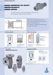
Installation2.6. Connection to the Compressed Air SystemDANGER!Compressed air!Operations to be performed by qualified personnel only.Never work on compressed air system under pressure.The user is responsible to <strong>en</strong>sure that the dryer will never be operated with pressure exceeding themaximum pressure rating on the unit data tag.Over-pressurizing the dryer could be dangerous for both the operator and the unit.The air temperature and the flow <strong>en</strong>tering the dryer must comply within the limits stated on the data nameplate. Thesystem connecting piping must be kept free from dust, rust, chips and other impurities, and must be consist<strong>en</strong>t with theflow-rate of the dryer. In case of treatm<strong>en</strong>t of air at particularly high temperature, the installation of a final refrigeratorcould result necessary. In order to perform maint<strong>en</strong>ance operations, it recomm<strong>en</strong>ded that a dryer by-pass system beinstalled as shown in the following illustration.Dryer Ø [BSP-F] A [in - mm]<strong>DRYPOINT</strong> <strong>RA</strong> <strong>HT</strong> <strong>20</strong>-50 <strong>NA</strong> 1/2” 3 1/2“ - 90<strong>DRYPOINT</strong> <strong>RA</strong> <strong>HT</strong> 75 <strong>NA</strong> 1” 15 7/8“ - 405<strong>DRYPOINT</strong> <strong>RA</strong> <strong>HT</strong> 100-150 <strong>NA</strong> 1.1/4” 18 11/16“ - 475<strong>DRYPOINT</strong> <strong>RA</strong> <strong>HT</strong> <strong>20</strong>0-250 <strong>NA</strong> 1.1/2” 23 3/8“ - 565<strong>DRYPOINT</strong> <strong>RA</strong> <strong>HT</strong> 300-<strong>350</strong> <strong>NA</strong> 2" 22 3/4“ - 575In realising the dryer, particular measures have be<strong>en</strong> tak<strong>en</strong> in order to limit the vibration which could occur during theoperation. Therefore we recomm<strong>en</strong>d to use connecting pipes able to insulate the dryer from possible vibrationsoriginating from the line (flexible hoses, vibration damping fittings, etc.).CAUTION:Piping the dryer, inlet/outlet connections must be supported as show in the diagram.Failing will result in damage.<strong>DRYPOINT</strong> <strong>RA</strong> <strong>HT</strong> <strong>20</strong> – <strong>350</strong> <strong>NA</strong> 9
Start up2.7. Electrical connectionsDANGER!Supply voltage!Qualified personnel should carry out connecting unit to the main power.Be sure to check the local codes in your area.Before connecting the unit to the electrical supply, verify the id<strong>en</strong>tification plate for the proper electrical information.Voltage tolerance is +/- 5%.Dryer supplied at 115/1/60 voltage comes with a mains connecting cable already installed and <strong>en</strong>ding with a North-American standard plug 2 poles + ground. Dryer supplied at 230/1/60, voltages comes with a box for the connection tothe mains.Be sure to provide the proper fuses or breakers based on the data information located on the nameplate.The mains socket must be provided with a mains magneto-thermal differ<strong>en</strong>tial breaker (I∆n=0.03A), adjusted on thebasis of the consumption of the dryer (see the nominal values on the data plate of the dryer). The cross section of thepower supply cables must comply with the consumption of the dryer, while keeping into account also the ambi<strong>en</strong>ttemperature, the conditions of the mains installation, the l<strong>en</strong>gth of the cables, and the requirem<strong>en</strong>ts <strong>en</strong>forced by thelocal Power Provider.DANGER!Mains voltage and missing earthing!Important: <strong>en</strong>sure that the plant is earthed.Do not use any socket adapters at the mains plug.If the mains plug needs to be replaced, this must only be done by a qualified electrician2.8. Cond<strong>en</strong>sate DrainDANGER!Compressed air and pressurized cond<strong>en</strong>sate!The cond<strong>en</strong>sate is discharge at the system pressure.Drain line should be secured.Never point the cond<strong>en</strong>sate drain line towards anybody.The dryer comes already fitted with an electronically level controlled BEKOMAT cond<strong>en</strong>sate drain. Connect andproperly fast<strong>en</strong> the cond<strong>en</strong>sate drain to a collecting plant or container.The drain cannot be connected to pressurized systems.Don’t dispose the cond<strong>en</strong>sate in the <strong>en</strong>vironm<strong>en</strong>t.The cond<strong>en</strong>sate collected in the dryer contains oil particles released in the air by the compressor.Dispose the cond<strong>en</strong>sate in compliance with the local rules.We suggest to install a water-oil separator where to convey all the cond<strong>en</strong>sate drain coming fromcompressors, dryers, tanks, filters, etc.3. Start up3.1. Preliminary OperationsCAUTION!Exceeding of operating parameters!Verify that the operating parameters match with the nominal values stated on the data nameplate of thedryer (voltage, frequ<strong>en</strong>cy, air pressure, air temperature, ambi<strong>en</strong>t temperature, etc.).This dryer has be<strong>en</strong> thoroughly tested, packaged and inspected prior to shipm<strong>en</strong>t. Nevertheless, the unit could bedamaged during transportation, check the integrity of the dryer during first start-up and monitor operation during thefirst hours of operation.Qualified personnel must perform the first start-up.Wh<strong>en</strong> installing and operating this equipm<strong>en</strong>t, comply with all National Electrical Code and any applicablefederal, state and local codes.Who is operating the unit is responsible for the proper and safe operation of the dryer.Never operate equipm<strong>en</strong>t with panels removed.
3.2. First start-upStart upThis procedure should be followed on first start-up, after periods of ext<strong>en</strong>ded shutdown or followingmaint<strong>en</strong>ance procedures.Qualified personnel must perform the start-up.Sequ<strong>en</strong>ce of operations (refer to paragraph 5.1 Control Panel).• Ensure that all the steps of the “Installation” chapter have be<strong>en</strong> observed.• Ensure that the connection to the compressed air system is correct and that the piping is suitably fixed andsupported.• Ensure that the cond<strong>en</strong>sate drain pipe is properly fast<strong>en</strong>ed and connected to a collection system or container.• Ensure that the by-pass system (if installed) is op<strong>en</strong> and the dryer is isolated• Ensure that the <strong>manual</strong> valve of the cond<strong>en</strong>sate drain circuit is op<strong>en</strong>.• Remove any packaging and other material which could obstruct the area around the dryer.• Activate the mains switch.• Turn on the main switch - pos. 1 on the control panel.• Ensure that the electronic instrum<strong>en</strong>t DMC14 is ON.• Ensure the consumption matches with the values of the data plate.• Ensure the fan work properly - wait for its first interv<strong>en</strong>tions (Air-Cooled).• Allow the dryer temperature to stabilise at the pre-set value.• Slowly op<strong>en</strong> the air inlet valve.• Slowly op<strong>en</strong> the air outlet valve.• Slowly close the c<strong>en</strong>tral by-pass valve of the system (if installed).• Check the piping for air leakage.• Ensure the drain is regularly cycling - wait for its first interv<strong>en</strong>tions.3.3. Start-up and shut downStart-up (refer to paragraph 5.1 Control Panel)• Check the cond<strong>en</strong>ser for cleanliness.• Verify that the system is powered.• Activate the main switch - pos. 1 on the control panel.• Ensure that electronic controller DMC14 is ON.• Wait a few minutes; verify that the DewPoint temperature displayed on electronic instrum<strong>en</strong>t DMC14 is correct andthat the cond<strong>en</strong>sate is regularly drained.• Switch on the air compressor.Shut down (refer to paragraph 5.1 Control Panel)• Verify that the DewPoint temperature displayed on electronic controller DMC14 is correct.• Switch OFF the air compressor.• After a few minutes, switch off the main switch on the control panel of the dryer (pos. 1).NOTE : A DewPoint within 32°F (0°C) and +60°F (15°C) displayed on DMC14 is correct according to thepossible working conditions (flow-rate, temperature of the incoming air, ambi<strong>en</strong>t temperature, etc.).During the operation, the refrigerating compressor will run continuously. The dryer must remain on during the fullusage period of the compressed air, ev<strong>en</strong> if the air compressor works intermitt<strong>en</strong>tly.The number of starts must be no more than 6 per hour. The dryer must stop running for at least 5minutes before being started up again.The user is responsible for compliance with these rules. Frequ<strong>en</strong>t starts may cause irreparable damage.<strong>DRYPOINT</strong> <strong>RA</strong> <strong>HT</strong> <strong>20</strong> – <strong>350</strong> <strong>NA</strong> 11
Technical Specifications4. Technical Specifications4.1. Technical Specifications <strong>DRYPOINT</strong> <strong>RA</strong> <strong>HT</strong> <strong>20</strong>-150 P (115/1/60) <strong>NA</strong>P (115/1/60)<strong>DRYPOINT</strong> <strong>RA</strong> <strong>HT</strong> <strong>NA</strong> MODEL<strong>20</strong> 30 40 50Air flow rate at nominal condition 1[scfm] <strong>20</strong>304050[m 3 /h] 34516885[l/min] 5668491132 1415Pressure DewPoint at nominal condition 1[°F – °C]≤ 45 - ≤ 7Nominal (max.) ambi<strong>en</strong>t temperature[°F – °C]100 (1<strong>20</strong>) - 38 (50)Min. ambi<strong>en</strong>t temperature[°F – °C]34 - 1Nominal (max.) inlet air temperature[°F – °C]180 (210) - 82 (100)Nominal inlet air pressure[psig – barg]100 - 7Max. inlet air pressure[psig – barg]230 - 16Air pressure drop - ∆p[psi – bar] 1.5 - 0.10 2.8 - 0.19 2.9 - 0.<strong>20</strong> 4.1 - 0.28Inlet - Outlet connections[NPT-F]1/2”Refrigerant typeR134.aRefrigerant quantity 2[oz – kg] 7 - 0.<strong>20</strong>8 - 0.2210.1/4 - 0.29Cooling air flow[cfm – m 3 /h]500 - 290Pre-Filter (3 micron)[model] S040S050S075Nominal refrigerating compressor power1/1<strong>01</strong>/81/61/5+Heat load[Btu/h] 1680 2100 2500 3600Standard Power Supply 2[Ph/V/Hz]115/1/60Nominal electric absorption[W] 210280310460[A] 2.32.53.14.7Max. electric absorption[W] 2403<strong>20</strong>360510[A] 2.73.03.95.1Max. level noise at 40 in (1m)[dbA]< 70Weight[lbs – kg] 66 - 30 68 - 31 71 - 32 73 - 331 The nominal condition refers to an ambi<strong>en</strong>t temperature of 100°F (38°C) with inlet air at 100psig (7barg) and 100°F (38°C).2 Check the data shown on the id<strong>en</strong>tification plate.757512721233.8 - 0.261”14 - 0.40900 - 5307708.38908.9110 - 50M<strong>01</strong><strong>01</strong>/3+6<strong>20</strong><strong>01</strong>0<strong>01</strong>0<strong>01</strong>702830<strong>20</strong>0 - 143.0 - 0.2116 - 0.451000 - 5908808.710<strong>20</strong>11.2134 - 611.1/4”15<strong>01</strong>5025542455.0 - 0.35R404A<strong>20</strong>.1/2 - 0.581500 - 880M<strong>01</strong>51/2850<strong>01</strong>10<strong>01</strong>0.11<strong>350</strong>12.2146 - 66
4.2. Technical Specifications <strong>DRYPOINT</strong> <strong>RA</strong> <strong>HT</strong> <strong>20</strong>-<strong>350</strong> E (230/1/60) <strong>NA</strong>Technical SpecificationsE (230/1/60)<strong>DRYPOINT</strong> <strong>RA</strong> <strong>HT</strong> <strong>NA</strong> MODEL <strong>20</strong> 30 40 50 75 100 150Air flow rate at nominal condition 1[scfm] <strong>20</strong> 30 40 50 75 100 150[m 3 /h] 34 51 68 85 127 170 255[l/min] 566 849 1132 1415 2123 2830 4245Pressure DewPoint at nominal condition 1[°F – °C]≤ 45 - ≤ 7Nominal (max.) ambi<strong>en</strong>t temperature[°F – °C]100 (1<strong>20</strong>) - 38 (50)Min. ambi<strong>en</strong>t temperature[°F – °C]34 - 1Nominal (max.) inlet air temperature[°F – °C]180 (210) - 82 (100)Nominal inlet air pressure[psig – barg]100 - 7Max. inlet air pressure[psig – barg]230 - 16Air pressure drop - ∆p[psi – bar] 1.5 - 0.10 2.8 - 0.19 2.9 - 0.<strong>20</strong> 4.1 - 0.28 3.8 - 0.26 3.0 - 0.21 5.0 -0.35Inlet - Outlet connections[NPT-F]1/2”1”1.1/4”Refrigerant typeR134.aRefrigerant quantity 2[oz – kg] 7- 0.<strong>20</strong>8 - 0.2210.1/4 – 0.29 14 - 0.40 16 - 0.45 <strong>20</strong>.1/2- 0.58Cooling air flow[cfm – m 3 /h]500 - 290900 - 530 1000 - 590 1500 - 880Nominal refrigerating compressor power1/1<strong>01</strong>/61/41/3+1/2Pre-Filter (3 micron)[model] S040S050S075M<strong>01</strong>0Heat load[Btu/h] 1680250040006<strong>20</strong>08500Standard Power Supply 2[Ph/V/Hz]230/1/60Nominal electric absorption[W] 210 280 310 460 770 880 1100[A] 1.1 1.3 1.6 2.3 4.2 4.3 5.1Max. electric absorption[W] 240 3<strong>20</strong> 360 510 890 10<strong>20</strong> 1<strong>350</strong>[A] 1.4 1.5 1.9 2.5 4.5 5.6 6.1Max. level noise at 40 in (1m)[dbA]< 70Weight[lbs – kg] 66 - 30 68 - 31 71- 32 73 - 33 110 - 50 134 - 61 146 - 661 The nominal condition refers to an ambi<strong>en</strong>t temperature of 100°F (38°C) with inlet air at 100psig (7barg) and 100°F (38°C).2 Check the data shown on the id<strong>en</strong>tification plate.<strong>20</strong>0250<strong>20</strong>025034042556607075<strong>20</strong>0 - 143.3 - 0.235.1 - 0.351.1/2”R404A30.1/2 - 0.8733.1/2 - 0.95<strong>350</strong>0 - <strong>20</strong>605000 - 29005/81.1/8M<strong>01</strong>51190<strong>01</strong>750<strong>01</strong>55<strong>01</strong>8<strong>20</strong>7.08.1165022807.310.4165 - 75185 - 84300<strong>350</strong>300<strong>350</strong>509594849099054.1 - 0.284.5 - 0.312”44 – 1.2550 – 1.406150 - 36006<strong>350</strong> - 370<strong>01</strong>.1/4M0<strong>20</strong><strong>20</strong>4002600270<strong>01</strong>2.112.8330034<strong>20</strong>15.<strong>01</strong>5.6291 - 132304 - 138<strong>DRYPOINT</strong> <strong>RA</strong> <strong>HT</strong> <strong>20</strong> – <strong>350</strong> <strong>NA</strong> 13
Technical description5. Technical description5.1. Control panelThe control panel illustrated below is the only dryer-operator interface.<strong>DRYPOINT</strong> <strong>RA</strong> <strong>HT</strong> <strong>20</strong> – 100 <strong>NA</strong>K10DMC14PQS000312 3<strong>DRYPOINT</strong> <strong>RA</strong> <strong>HT</strong> 150 – <strong>350</strong> <strong>NA</strong>IONK°C°FDMC 14setescPQS00041 231 Main switch 3 Air and refrigerating gas flow diagram2 Electronic control instrum<strong>en</strong>t DMC145.2. OperationOperating principal – The dryer models described in this <strong>manual</strong> all operate on the same principal. First the very hotmoisture lad<strong>en</strong> air directly from the compressor <strong>en</strong>ters the aftercooler (copper tube / aluminum fin cooling surface) whereit is cooled to within 18-<strong>20</strong>°F (10-12°C) of the ambi<strong>en</strong>t air temperature. It leaves the aftercooler with <strong>en</strong>trained cond<strong>en</strong>sedwater droplets which are separated by the 1 micron bulk liquid filter separator elem<strong>en</strong>t and drained away by the first drainsystem. The partially cooled moisture lad<strong>en</strong> air next <strong>en</strong>ters an air to air heat exchanger to pre-cool it. The compressed airnext goes through the evaporator, also known as the air to refrigerant heat exchanger. The compressed air temperatureis reduced to approximately 41°F (5°C), causing additional water vapor to cond<strong>en</strong>se to liquid. The liquid is continuouslycoalesced and collected in the dryer separator for automatic removal by the second cond<strong>en</strong>sate drain. The cool moisturefree compressed air th<strong>en</strong> passes back through the air to air heat exchanger to be reheated to within the ambi<strong>en</strong>ttemperature as it exits the dryer.Refrigerant circuit - Refrigerant gas is cycled through the compressor and exits at high pressure to a cond<strong>en</strong>ser whereheat is removed causing the refrigerant to cond<strong>en</strong>se to a high-pressure liquid state. The liquid is forced through acapillary tube where the resulting pressure drop allows the refrigerant to boil off at a predetermined temperature. Lowpressureliquid refrigerant <strong>en</strong>ters the heat exchanger where heat from the incoming air is transferred causing therefrigerant to boil; the resulting phase change produces a low pressure, low temperature gas. The low-pressure gas isreturned to the compressor, where it is re-compressed and begins the cycle again. During those periods wh<strong>en</strong> thecompressed air load is reduced the excess refrigerant is by-passed automatically back to the compressor via the HotGas By-pass Valve circuit.
Technical description5.3. Flow Diagram272623 4 5P B PAP VT S9 M2861a711b81cT11211 10DGF00361321211 Alu-Dry Module 9 Cond<strong>en</strong>ser fana - Air-to-air heat exchanger 10 Filter drierb - Air-to-refrigerant exchanger 11Capillary tubec - Cond<strong>en</strong>sate separator 12 T1 Temperature probe (DewPoint)Refrigerant pressure-switch P2B (<strong>DRYPOINT</strong> <strong>RA</strong>13 Cond<strong>en</strong>sate drain isolation valve<strong>HT</strong> 300-<strong>350</strong> <strong>NA</strong>)Safety thermo-switch T3S (<strong>DRYPOINT</strong> <strong>RA</strong> <strong>HT</strong>150-<strong>350</strong> <strong>NA</strong>)…Refrigerant pressure-switch P4A (<strong>DRYPOINT</strong> <strong>RA</strong><strong>HT</strong> 300-<strong>350</strong> <strong>NA</strong>)21 <strong>Beko</strong>mat drainer5 Refrigerant Fan pressure-switch P V …6 Refrigeration compressor 26 Aftercooler7 Hot gas by-pass valve 27 Aftercooler fan (<strong>DRYPOINT</strong> <strong>RA</strong> <strong>HT</strong> 75-<strong>350</strong> <strong>NA</strong>)8 Cond<strong>en</strong>ser 28 Pre-Filter (1 micron)Compressed air flow directionRefrigerating gas flow direction<strong>DRYPOINT</strong> <strong>RA</strong> <strong>HT</strong> <strong>20</strong> – <strong>350</strong> <strong>NA</strong> 15
Technical description5.4. Refrigerating compressorThe refrigerating compressor is the pump in the system, gas coming from the evaporator (low pressure side) iscompressed up to the cond<strong>en</strong>sation pressure (high pressure side). The compressors utilized are manufactured byleading manufacturers and are designed for applications where high compression ratios and wide temperaturechanges are pres<strong>en</strong>t.The hermetically sealed construction is perfectly gas tight, <strong>en</strong>suring high-<strong>en</strong>ergy effici<strong>en</strong>cy and long, useful life.Dumping springs support the pumping unit in order to reduce the acoustic emission and the vibration diffusion. Theaspirated refrigerating gas, flowing through the coils before reaching the compression cylinders cools the electricmotor. The thermal protection protects the compressor from over heating and over curr<strong>en</strong>ts. The protection isautomatically restored as soon as the nominal temperature conditions are reached.5.5. Cond<strong>en</strong>serThe cond<strong>en</strong>ser is the compon<strong>en</strong>t in which the gas coming from the compressor is cooled down and cond<strong>en</strong>sedbecoming a liquid. Mechanically, a serp<strong>en</strong>tine copper tubing circuit (with the gas flowing inside) is <strong>en</strong>capsulated in analuminum fin package.The cooling operation occurs via a high effici<strong>en</strong>cy fan, creating airflow within the dryer, moving air through the finpackage. It’s mandatory that the ambi<strong>en</strong>t air temperature does not exceed the nominal values. It is also important tokeep the cond<strong>en</strong>ser unit free from dust and other impurities.5.6. AftercoolerThe aftercooler is the elem<strong>en</strong>t where the incoming hot air undergoes the cooling stage. Mechanically, it is formed by acopper tubing circuit (with the compressed air flowing inside) immersed in an aluminium blades package. The coolingoperation occurs via a high effici<strong>en</strong>cy axial v<strong>en</strong>tilator which, in applying pressure on the air contained within the dryer,forces it into the blades package. In models <strong>DRYPOINT</strong> <strong>RA</strong> <strong>HT</strong> <strong>20</strong>-50 <strong>NA</strong> the aftercooler is combined with the dryer’scond<strong>en</strong>ser, thus forming just one heat exchanger battery, cooled by just one high effici<strong>en</strong>cy axial fan.It is mandatory that the temperature of the ambi<strong>en</strong>t air will not exceed the nominal values of the dryer. It is importantTO KEEP THE UNIT FREE FROM DUST AND OTHER IMPURITIES tak<strong>en</strong> in by the fan.5.7. Pre-Filter (1 micron)Positioned at the outlet of the aftercooler, it assures a good air cleanliness level, in addition to the complete removal ofthe water cond<strong>en</strong>sed in the aftercooler. REPLACE THE FILTERING ELEMENT (CARTRIDGE) AT LEAST EVERY 12MONTHS.5.8. Capillary TubeIt consists of a piece of reduced cross section copper tubing located betwe<strong>en</strong> the cond<strong>en</strong>ser and the evaporator, actingas a metering device to reduce the pressure of the refrigerant. Reduction of pressure is a design function to achieveoptimum temperature reached within the evaporator: the smaller the capillary tube outlet pressure, the lower theevaporation temperature.The l<strong>en</strong>gth and interior diameter of the capillary tubing is accurately sized to establish the performance of the dryer; nomaint<strong>en</strong>ance or adjustm<strong>en</strong>t is necessary.5.9. Alu-Dry ModuleThe air-to-air and the air-to-refrigerant heat exchangers plus the demister type cond<strong>en</strong>sate separator are housed in aunique module.The counter-flows of compressed air in the air-to-air heat exchanger <strong>en</strong>sure maximum heat transfer. The large crosssection of flow channels within the heat exchanger module leads to low velocities and reduced power requirem<strong>en</strong>ts.The air-to-refrigerant exchanger, with counter-curr<strong>en</strong>t flows, assure excell<strong>en</strong>t performances. The g<strong>en</strong>erous dim<strong>en</strong>sionsof the exchange surface determines the correct and complete evaporation of the refrigerant (prev<strong>en</strong>ting liquid returningto the compressor). The high effici<strong>en</strong>cy cond<strong>en</strong>sate separator is located within the drying module. No maint<strong>en</strong>ance isrequired and it offers the additional advantage of creating a cold coalescing effect for excell<strong>en</strong>t air drying results. Theg<strong>en</strong>erous collection volume assures the correct operation of the dryer ev<strong>en</strong> with extremely damp inlet air.
5.10. Hot Gas By-pass ValveTechnical descriptionThis valve injects part of the hot gas (tak<strong>en</strong> from the discharge side of the compressor) in the pipe betwe<strong>en</strong> theevaporator and the suction side of the compressor, keeping the evaporation temperature/pressure constant at approx.36°F (+2 °C). This injection prev<strong>en</strong>ts the formation of ice inside the dryer evaporator at every load condition.ADJUSTMENTThe Hot Gas By-pass Valve is adjusted during the manufacturing testingphase. As a rule no adjustm<strong>en</strong>t is required; anyway if it is necessary theoperation must be carried out by an experi<strong>en</strong>ced refrigerating <strong>en</strong>gineer.WARNING!the use of ¼” Schrader service valves must be justified by a real malfunctionof the refrigerating system. Each time a pressure gauge is connected, a partof refrigerant is exhausted.Without compressed air flow through the dryer, rotate the adjusting screw(position A on the drawing) until the following value is reached:Hot gas setting (R134.a) :Hot gas setting (R404A) :temperature 33°F (+1 / -0 °F)pressure 29 psig (+1.5 / -0 psi)temperature 0.5°C (+0.5 / -0 °K)pressure 2.0 barg (+0.1 / -0 bar)temperature 33°F (+1 / -0 °F)pressure 75.4 psig (+1.5 / -0 psi)temperature 0.5 °C (+0.5 / -0 °K)pressure 5.2 barg (+0.1 / -0 bar)VLY00<strong>01</strong>-+A4 mm5/32 in.5.11. Refrigerant Pressure Switches P A -P B -P VAs operation safety and protection of the dryer a series of pressure switches are installed in the gas circuit.PB : Low-pressure controller device on the pushing side (carter) of the compressor, is <strong>en</strong>abled only if the pressuredrops below the pre-set value. The values are automatically reset wh<strong>en</strong> the nominal conditions are restored.Calibrated pressure : R 404 A Stop 14.5 psig - Restart 72.5 psigR 404 A Stop 1.0 barg - Restart 5.0 bargPA : This high-pressure controller device, located on the pushing side on the compressor, is activated wh<strong>en</strong> the pressureexceeds the pre-set value. It features a <strong>manual</strong>-resetting button mounted on the controller itself.Calibrated pressure : R 404 A Stop 464 psig - Manual resetR 404 A Stop 32 barg - Manual resetPV : Fan control pressure switch is placed at the discharge side of refrigeration compressor. It keeps the cond<strong>en</strong>sationtemperature/pressure constant within preset limits (Air-Cooled).Calibrated pressure : R 134.a Start 160 psig (117°F) - Stop 116 psig (97°F) - Tolerance ± 15 psiR 134.aR 404 AR 404 AStart 11 barg (47°C) - Stop 8 barg (36°C) - Tolerance ± 1 barStart 290 psig (113°F) - Stop 232 psig (97°F) - Tolerance ± 15 psiStart <strong>20</strong> barg (45°C) - Stop 16 barg (36°C) - Tolerance ± 1 bar5.12. Safety thermo-switch T s2To protect the operating safety and the integrity of the dryer, a thermo-switch (T S )is installed on the refrigerant gas circuit. The thermo-switch s<strong>en</strong>sor, in case ofunusual discharge temperatures, stops the refrigerating compressor before it isperman<strong>en</strong>tly damaged.PQS00051Manually reset the thermo-switch only after the nominal operating conditions havebe<strong>en</strong> restored. Unscrew the relative cap (see pos.1 in the figure) and press thereset button (see pos.2 in the figure).TS setting :temperature 212 °F (+4 / -4 °F)temperature 100 °C (+2 / -2 °K)<strong>DRYPOINT</strong> <strong>RA</strong> <strong>HT</strong> <strong>20</strong> – <strong>350</strong> <strong>NA</strong> 17
Technical description5.13. DMC14 Electronic Instrum<strong>en</strong>t (Air Dryer Controller)PQS0006setDISPLAY°C°FescDMC 14setescTaste - access the set-up.Taste - Exit programming / decrease value.Taste - Value increm<strong>en</strong>t.LED - Dryer in alarm status.● °C LED - Display the set temperature scale (°C).● °F LED - Display the set temperature scale (°F).● LED - Not usedThrough the digital thermometer with an alphanumerical display, the DMC14 controller shows the DewPoint detectedby the probe in the evaporator.The LED shows any alarm condition, it can happ<strong>en</strong> wh<strong>en</strong> :• pressure DewPoint is too high;• pressure DewPoint is too low;• the probe is faulty.If the probe is faulty, the instrum<strong>en</strong>t also shows “PF” message (Probe Failure), and alarm activation is immediate. Incase of “DewPoint too low” condition (ASL parameter, that is fix and equal to 28.5°F or -2°C), the alarm signal isdelayed of a fix time (AdL parameter) equal to 30 sec, while for “DewPoint too high” condition the value (ASHparameter) is set by the user and the signal is activated with AdH delay time, that can be also set up by the operator(the instrum<strong>en</strong>t is already adjusted during final test of the dryer, please see following values). Wh<strong>en</strong> DewPoint returnsinto operating temperature (set range), the alarm condition is deactivated.DMC14 allows also remote annunciation of the alarm condition of the dryer; this through a volt free contact onterminals 8 & 9 - please also see electric drawings into the attachm<strong>en</strong>ts (max 250V 1A, min 5VDC 10mA)• with dryer off or in alarm conditions contact is op<strong>en</strong>• with dryer on and correct operating DewPoint, contact is closed.OPE<strong>RA</strong>TION - After dryer starting, the electronic controller displays curr<strong>en</strong>t operating DewPoint : it shows themeasured temperature in Celsius degrees (● °C) with a 0.5°C resolution, or in Fahr<strong>en</strong>heit degrees (● °F) with a 1°Fresolution.SET-UP (PROG<strong>RA</strong>MMING)To access the set-up, keep pressed simultaneously bothsetand button for at least 5 seconds. In this wayprogramming operation will be activated and the controller display shows the first parameter that can be set (Ton).After that, by pressingsetbuttom the display shows the value set for that parameter. If the value is correct presssetbutton to conferm it and to give access on following parameters. To change the value of selected parameter,must be usedescand button, respectively to decrease or increase the value. All parameters that can bemodified are indicated in following table :Display Description Value range Set value Equal toTon Not used <strong>01</strong> … <strong>20</strong> 02 2 secToF Not used <strong>01</strong> … <strong>20</strong> <strong>01</strong> 1 minASH Alarm threshold for a high DewPoint . 0.0 … 68.0 60 60°FAdH ASH alarm time before signal 00 … <strong>20</strong> <strong>20</strong> <strong>20</strong> minSCL Temperature scale °C … °F °F °Fahr<strong>en</strong>heitFixed parameters : ASL (low DewPoint alarm) = -2°C or 28.5°F AdL (signal delay) = 30 secescIt is possibile to exit from set-up conditon in any mom<strong>en</strong>t, by pressing simultaneously both and button. Ifany operations are not made during 30 seconds, the controller exits automatically from programming operation.
5.14. Electronic level controlled cond<strong>en</strong>sate drain BEKOMATTechnical descriptionThe electronic level controlled drain BEKOMAT has a special cond<strong>en</strong>sate managem<strong>en</strong>t that makes sure thatcond<strong>en</strong>sate is drained safely without any unnecessary air-loss. This drain consists of a cond<strong>en</strong>sate accumulator wherea capacitive s<strong>en</strong>sor continuously checking liquid level is placed: as soon as the accumulator is filled, the s<strong>en</strong>sor passesa signal to the electronic control and a diaphragm sol<strong>en</strong>oid valve will op<strong>en</strong> to discharge the cond<strong>en</strong>sate. Right in timethe discharge line will be closed again without wasting compressed air.ATTENTION!These BEKOMAT cond<strong>en</strong>sate drains have be<strong>en</strong> specially designed for the use in a refrigerant dryer <strong>DRYPOINT</strong> <strong>RA</strong><strong>HT</strong> <strong>NA</strong>. Any Installation in other compressed air treatm<strong>en</strong>t units or the exchange against a differ<strong>en</strong>t drain brand maylead to malfunction. Do not exceed the max. operating pressure (see type plate)!Make sure wh<strong>en</strong> the dryer starts the upstream valve is op<strong>en</strong>.NOTE:For detailed information on drainer functions, troubleshooting, service and replacem<strong>en</strong>t parts, please refer tothe BEKOMAT drainer <strong>manual</strong>.<strong>DRYPOINT</strong> <strong>RA</strong> <strong>HT</strong> <strong>20</strong> – <strong>350</strong> <strong>NA</strong> 19
Maint<strong>en</strong>ance, troubleshooting, spares and dismantling6. Maint<strong>en</strong>ance, troubleshooting, spares and dismantling6.1. Controls and Maint<strong>en</strong>anceDANGER!Compressed air, mains voltage, unqualified personnel!Only qualified personnel should perform troubleshooting and or maint<strong>en</strong>ance operations.Prior to performing any maint<strong>en</strong>ance or service, be sure that:• no part of the machine is powered and that it cannot be connected to the mains supply.• no part of the machine is under pressure and that it cannot be connected to the compressed airsystem.• Maint<strong>en</strong>ance personnel have read and understand the safety and operation instructions in this<strong>manual</strong>.Before attempting any maint<strong>en</strong>ance operation on the dryer, shut it down and wait at least 30 minutes.DANGER!Hot surfaces!Some compon<strong>en</strong>ts can reach high temperature during operation. Avoid contact until system or compon<strong>en</strong>thas dissipated heat.DAILY:Verify that the DewPoint displayed on the electronic instrum<strong>en</strong>t is correct.Check the proper operation of the cond<strong>en</strong>sate drain systems.Verify the cond<strong>en</strong>ser for cleanliness.EVERY <strong>20</strong>0 HOURS OR MONTHLYWith an air jet (max. 2 bar / 30 psig) blowing from inside towards outside clean thecond<strong>en</strong>ser; repeat this operation blowing in the opposite way; be careful not todamage the aluminum fins of the cooling package.• At the <strong>en</strong>d, check the operation of the machine.EVERY 1000 HOURS OR YEARLY• Verify for tightness all the screws of the electric system and that all the “Faston” type connections are intheir proper position, inspect unit for brok<strong>en</strong>, cracked or bare wires.• Inspect refrigerating circuit for signs of oil and refrigerant leakage.• Measure and record amperage. Verify that readings are within acceptable parameters as listed inspecification table.• Inspect cond<strong>en</strong>sate drain flexible hoses, and replace if necessary.• Replace the filter elem<strong>en</strong>t (cartridge) of the Pre-Filter (1 micron). Refer to the instructions in the user’s andmaint<strong>en</strong>ance <strong>manual</strong> of the filter for this operation.• At the <strong>en</strong>d, check the operation of the machine.
Maint<strong>en</strong>ance, troubleshooting, spares and dismantling6.2. TroubleshootingOnly qualified personnel should perform troubleshooting and or maint<strong>en</strong>ance operations.Prior to performing any maint<strong>en</strong>ance or service, be sure that:• no part of the machine is powered and that it cannot be connected to the mains supply.• no part of the machine is under pressure and that it cannot be connected to the compressed airsystem.• Maint<strong>en</strong>ance personnel have read and understand the safety and operation instructions in this<strong>manual</strong>.Before attempting any maint<strong>en</strong>ance operation on the dryer, shut it down and wait at least 30 minutes.Some compon<strong>en</strong>ts can reach high temperature during operation. Avoid contact until system or compon<strong>en</strong>thas dissipated heatSYMPTOM The dryer doesn'tstart. The compressordoesn’t work. The fan of thecond<strong>en</strong>ser doesn’twork. <strong>DRYPOINT</strong> <strong>RA</strong> <strong>HT</strong>75-<strong>350</strong> <strong>NA</strong> - TheAftercooler fan doesn’twork. DewPoint too high.POSSIBLE CAUSE - SUGGESTED ACTION Verify that the system is powered. Verify the electric wiring. Activation of the compressor internal thermal protection - wait for 30 minutes, th<strong>en</strong>retry. Verify the electric wiring. Where installed - Replace the internal thermal protection and/or the start-up relayand/or the start-up capacitor and/or the working capacitor. Where installed - The pressure switch PA has be<strong>en</strong> activated - see specific point. Where installed - The pressure switch PB has be<strong>en</strong> activated - see specific point. Where installed- The safety thermo-switch TS has be<strong>en</strong> activated - see specificpoint. If the compressor still doesn’t work, replace it. Verify the electric wiring. PV pressure switch is faulty - replace it. There is a leak in the refrigerating fluid circuit - contact a refrigeration <strong>en</strong>gineer. If the fan still doesn't work, replace it. Verify the electric wiring. If the fan still doesn't work, replace it. The dryer doesn't start - see specific point. The T1 DewPoint probe doesn’t correctly detect the temperature - <strong>en</strong>sure the s<strong>en</strong>soris pushed into the bottom of copper tube immersion well. The refrigerating compressor doesn’t work - see specific point. The ambi<strong>en</strong>t temperature is too high or the room aeration is insuffici<strong>en</strong>t - provideproper v<strong>en</strong>tilation. The inlet air is too hot - restore the nominal conditions. The inlet air pressure is too low - restore the nominal conditions. The inlet air flow rate is higher than the rate of the dryer - reduce the flow rate -restore the normal conditions. The cond<strong>en</strong>ser is dirty - clean it. The aftercooler is dirty - clean it. The cond<strong>en</strong>ser fan doesn’t work - see specific point. The aftercooler fan doesn’t work - see specific point. The dryer doesn’t drain the cond<strong>en</strong>sate - see specific point. The hot gas by-pass valve is out of setting - contact a refrigeration <strong>en</strong>gineer to restorethe nominal setting. There is a leak in the refrigerating fluid circuit - contact a refrigeration <strong>en</strong>gineer.<strong>DRYPOINT</strong> <strong>RA</strong> <strong>HT</strong> <strong>20</strong> – <strong>350</strong> <strong>NA</strong> 21
Maint<strong>en</strong>ance, troubleshooting, spares and dismantling DewPoint too low. Excessive pressuredrop within the dryer. The dryer doesn’t drainthe cond<strong>en</strong>sate. The dryer continuouslydrains cond<strong>en</strong>sate. Water within the line. Where installed - ThePA high-pressureswitch has be<strong>en</strong>activated. Where installed - ThePB low-pressureswitch has be<strong>en</strong>activated. Where installed - TheTS safety thermoswitchhas be<strong>en</strong>activated. DMC14 - The LEDof theinstrum<strong>en</strong>t is on orflashes to indicatealarm situations. The fan is always ON - PV pressure switch is faulty - replace it. The Hot Gas By-pass Valve is out of setting - contact a refrigeration <strong>en</strong>gineer torestore the nominal setting. Ambi<strong>en</strong>t temperature is too low - restore de nominal condition. The Pre-Filter (1 micron) is clogged - replace the filter elem<strong>en</strong>t (cartridge) - Refer tothe instructions in the user’s and maint<strong>en</strong>ance <strong>manual</strong> of the filter. The dryer doesn’t drain the cond<strong>en</strong>sate - see specific point. The DewPoint is too low - the cond<strong>en</strong>sate is frost and blocks the air - see specificpoint. Check for throttling the flexible connection hoses. The cond<strong>en</strong>sate drain service valve is closed - op<strong>en</strong> it. Verify the electric wiring. The DewPoint is too low - the cond<strong>en</strong>sate is froz<strong>en</strong> - see specific point. <strong>Beko</strong>mat drainer is not operating correctly (see BEKOMAT MANUAL) <strong>Beko</strong>mat drainer is dirty (see BEKOMAT MANUAL) The dryer doesn't start - see specific point. Where installed - Untreated air flows through the by-pass unit - close the by-pass. The dryer doesn’t drain the cond<strong>en</strong>sate - see specific point. DewPoint too high - see specific point. Check which of the following has caused the activation :1. The ambi<strong>en</strong>t temperature is too high or the room aeration is insuffici<strong>en</strong>t - provide properv<strong>en</strong>tilation.2. The cond<strong>en</strong>ser is dirty - clean it.3. The cond<strong>en</strong>ser fan doesn’t work - see specific point. Reset the pressure-switch pressing the button on the controller itself - verify the dryerfor correct operation. The PA pressure switch is faulty - contact a refrigeration <strong>en</strong>gineer to replace it. There is a leak in the refrigerating fluid circuit - contact a refrigeration <strong>en</strong>gineer. The pressure switch restores automatically wh<strong>en</strong> normal conditions are restored -check the proper operation of the dryer. Check which of the following has caused the activation :1. Eccessive thermal load – restore the standard operating conditions.2. The inlet air is too hot - restore the nominal conditions.3. The ambi<strong>en</strong>t temperature is too high or the room aeration is insuffici<strong>en</strong>t - provide properv<strong>en</strong>tilation.4. The cond<strong>en</strong>ser unit is dirty - clean it.5. The fan doesn’t work - see specific point.6. There is a leak in the refrigerating fluid circuit - contact a refrigeration <strong>en</strong>gineer. Reset the thermo-switch by pressing the button on the thermo-switch itself – verify thecorrect operation of the dryer. The TS thermo-switch is faulty - replace it. The LED The LEDflashes because the DewPoint is too high – see specific point.flashes because the DewPoint is too low - see specific point. The LED flashes because the probe is faulty or interrupted, the instrum<strong>en</strong>tdisplays the message “PF” (Probe Failure) – replace the probe.
6.3. Spare PartsMaint<strong>en</strong>ance, troubleshooting, spares and dismantlingThe suggested spare parts list will <strong>en</strong>able you to promptly interv<strong>en</strong>e in case of abnormal operation, so avoiding to waitfor the spares delivery. In case of failure of other parts, for example inside the refrigerating circuit, the replacem<strong>en</strong>tmust be worked out by a refrigerating systems specialist or in our factory.NOTE: To order the suggested spare parts or any other part, it’s necessary to quote the data reported on theid<strong>en</strong>tification plate.N.DESCRIPTIONOF THE SPARE PARTSCODE<strong>DRYPOINT</strong> <strong>RA</strong> <strong>HT</strong> <strong>NA</strong> P 115V<strong>20</strong> 30 40 50 75 100 1503 Safety thermo-switch TS 56141NN005 15 Fan pressure switch P V 5655NNN170 1 1 1 1 1 1 16 Compressor 5<strong>01</strong>51351<strong>01</strong> 16 Compressor 5<strong>01</strong>5135103 16 Compressor 5<strong>01</strong>5135105 16 Compressor 5<strong>01</strong>51<strong>350</strong>07 16 Compressor 5<strong>01</strong>51<strong>350</strong>11 1 16 Compressor 503<strong>01</strong><strong>350</strong>05 17 Hot Gas By-pass Valve 64140SS160 1 1 1 1 1 17 Hot Gas By-pass Valve 64140SS155 19.1 Fan motor 521<strong>01</strong>15<strong>01</strong>5 1 1 1 19.1 Fan motor 521<strong>01</strong><strong>350</strong>10 19.1 Fan motor 521<strong>01</strong><strong>350</strong><strong>20</strong> 1 19.2 Fan blade 5215000022 1 1 1 19.2 Fan blade 5215000<strong>01</strong>9 19.2 Fan blade 5215000025 1 19.3 Fan grid 5225000<strong>01</strong>0 1 1 1 1 19.3 Fan grid 5225000027 1 110 Filter Drier 6650SSS007 1 1 1 1 1 110 Filter Drier 6650SSN150 112 Temp. probe DMC14 (T1) L.1<strong>20</strong>0 5625NNN035 12 Temp. probe DMC14 (T1) L.1<strong>20</strong>0 5625NNN037 17 DMC14 Electronic control instrum<strong>en</strong>t 56<strong>20</strong>13<strong>01</strong>03 1 1 1 1 1 1 121 BEKOMAT 31 BM31 BI (supply voltage) 2 2 2 2 2 221 BEKOMAT 32 Vario BM32 V BI (supply voltage) 222 Seccionador g<strong>en</strong>eral 2P 0/1 5450SZN<strong>01</strong>0 1 1 1 1 1 122 Seccionador g<strong>en</strong>eral 2P 0/1 5450SZN117 127.1 Motor del v<strong>en</strong>tilador 521<strong>01</strong><strong>350</strong><strong>20</strong> 1 127.1 Motor del v<strong>en</strong>tilador 521<strong>01</strong><strong>350</strong>21 127.2 Impulsor del v<strong>en</strong>tilador 5215000022 127.2 Impulsor del v<strong>en</strong>tilador 5215000025 127.2 Impulsor del v<strong>en</strong>tilador 5215000032 127.3 Fan grid 5225000<strong>01</strong>5 127.3 Fan grid 5225000025 1 128.1 Cartridge for S040 Pre-Filter 04F 28.1 Cartridge for S050 Pre-Filter 05F 28.1 Cartridge for S075 Pre-Filter 07F 28.1 Cartridge for M<strong>01</strong>0 Pre-Filter 10F 28.1 Cartridge for M<strong>01</strong>5 Pre-Filter 15F Suggested spare part.<strong>DRYPOINT</strong> <strong>RA</strong> <strong>HT</strong> <strong>20</strong> – <strong>350</strong> <strong>NA</strong> 23
Maint<strong>en</strong>ance, troubleshooting, spares and dismantlingN.DESCRIPTIONOF THE SPARE PARTSCODE<strong>DRYPOINT</strong> <strong>RA</strong> <strong>HT</strong> <strong>NA</strong> E 230V<strong>20</strong> 30 40 50 75 100 150 <strong>20</strong>0 250 300 <strong>350</strong>2 Refrigerant gas pressure switch PB 5655NNN085 1 13 TS safety thermo-switch 56141NN005 1 1 1 1 14 Refrigerant gas pressure switch PA 5655NNN087 1 15 Refrigerant gas pressure switch PV 5655NNN170 1 1 1 1 1 1 1 1 1 1 16 Refrigerating compressor 5<strong>01</strong>511<strong>01</strong><strong>01</strong> 16 Refrigerating compressor 5<strong>01</strong>511<strong>01</strong>07 1 16 Refrigerating compressor 5<strong>01</strong>511<strong>01</strong>13 16 Refrigerating compressor 5<strong>01</strong>5115<strong>01</strong>1 1 16 Refrigerating compressor 503<strong>01</strong>15005 16 Refrigerating compressor 503<strong>01</strong>15<strong>01</strong>5 16 Refrigerating compressor 503<strong>01</strong>150<strong>20</strong> 16 Refrigerating compressor 503<strong>01</strong>15025 1 17 Hot gas by-pass valve 64140SS160 1 1 1 1 1 17 Hot gas by-pass valve 64140SS155 1 1 1 1 19 Complete fan 525<strong>01</strong>1<strong>01</strong>00 1 19 Complete fan 525<strong>01</strong>15005 19.1 Fan motor 521<strong>01</strong>10<strong>01</strong>2 19.1 Fan motor 521<strong>01</strong>10<strong>01</strong>8 1 1 1 1 1 19.1 Fan motor 521<strong>01</strong>10022 19.2 Fan blade 5215000022 1 1 1 19.2 Fan blade 5215000<strong>01</strong>9 19.2 Fan blade 5215000025 1 19.2 Fan blade 5215000035 19.3 Fan grid 5225000<strong>01</strong>0 1 1 1 1 19.3 Fan grid 5225000027 1 19.3 Fan grid 5225000030 110 Filter Drier 6650SSS007 1 1 1 1 1 110 Filter Drier 6650SSN150 110 Filter Drier 6650SSN160 1 1 1 112 Temp. probe DMC14 (T1) L.1<strong>20</strong>0 5625NNN035 12 Temp. probe DMC14 (T1) L.1<strong>20</strong>0 5625NNN037 17DMC14 Electronic controlinstrum<strong>en</strong>t56<strong>20</strong>11<strong>01</strong>03 1 1 1 1 1 1 1 1 1 1 121 BEKOMAT 31BM31 BI(supply voltage)2 2 2 2 2 221 BEKOMAT 32 VarioBM32 V BI(supply voltage)2 2 2 2 222 Main switch 2P 0/1 5450SZN<strong>01</strong>0 1 1 1 1 1 122 Main switch 2P 0/1 5450SZN117 1 1 1 1 127 Complete fan 525<strong>01</strong>15005 1 127 Complete fan 525<strong>01</strong>1<strong>01</strong>10 1 127.1 Fan motor 521<strong>01</strong>10<strong>01</strong>8 1 127.1 Fan motor 521<strong>01</strong>10022 127.2 Fan blade 5215000022 127.2 Fan blade 5215000025 127.2 Fan blade 5215000032 127.3 Fan grid 5225000<strong>01</strong>5 127.3 Fan grid 5225000025 1 128.1 Cartridge for S040 Pre-Filter 04F 28.1 Cartridge for S050 Pre-Filter 05F 28.1 Cartridge for S075 Pre-Filter 07F 28.1 Cartridge for M<strong>01</strong>0 Pre-Filter 10F 28.1 Cartridge for M<strong>01</strong>5 Pre-Filter 15F 28.1 Cartridge for S040 Pre-Filter <strong>20</strong>F Suggested spare part.
6.4. Maint<strong>en</strong>ance operation on the refrigerating circuitMaint<strong>en</strong>ance, troubleshooting, spares and dismantlingCAUTION!Refrigerant!Maint<strong>en</strong>ance and service on refrigerating systems must be carried out only by certified refrigerating<strong>en</strong>gineers only, according to local rules.All the refrigerant of the system must be recovered for its recycling, reclamation or destruction.Do not dispose the refrigerant fluid in the <strong>en</strong>vironm<strong>en</strong>t.This dryer comes ready to operate and filled with R134a or R404A type refrigerant fluid.In case of refrigerant leak contact a certified refrigerating <strong>en</strong>gineers. Room is to be aired before anyinterv<strong>en</strong>tion.If is required to re-fill the refrigerating circuit, contact a certified refrigerating <strong>en</strong>gineers.Refer to the dryer nameplate for refrigerant type and quantity.Characteristics of refrigerants used:Refrigerant Chemical formula TLV GWPR134a - HFC CH2FCF3 1000 ppm 1300R404A - HFC CH2FCF3/C2HF5/C2H3F3 1000 ppm 37846.5. Dismantling of the DryerIf the dryer is to be dismantled, it has to be split into homog<strong>en</strong>eous groups of materials.PartMaterialRefrigerant fluidR404A, R134a, OilCanopy and SupportsCarbon steel, Epoxy paintRefrigerating compressorSteel, Copper, Aluminium, OilAlu-Dry ModuleAluminiumCond<strong>en</strong>ser UnitAluminium, Copper, Carbon steelPipeCopperFanAluminium, Copper, SteelValveBrass, SteelElectronic Level DrainPVC, Aluminium, SteelInsulation MaterialSynthetic gum without CFC, Polystyr<strong>en</strong>e, PolyurethaneElectric cableCopper, PVCElectric PartsPVC, Copper, BrassWe recomm<strong>en</strong>d to comply with the safety rules in force for the disposal of each type of material.The chilling fluid contains droplets of lubrication oil released by the refrigerating compressor.Do not dispose this fluid in the <strong>en</strong>vironm<strong>en</strong>t. Is has to be discharged from the dryer with a suitable deviceand th<strong>en</strong> delivered to a collection c<strong>en</strong>tre where it will be processed to make it reusable.<strong>DRYPOINT</strong> <strong>RA</strong> <strong>HT</strong> <strong>20</strong> – <strong>350</strong> <strong>NA</strong> 25
List of attachm<strong>en</strong>ts7. List of attachm<strong>en</strong>ts7.1. Dryers Dim<strong>en</strong>sions7.1.1. Dryers Dim<strong>en</strong>sions <strong>DRYPOINT</strong> <strong>RA</strong> <strong>HT</strong> <strong>20</strong>-50 <strong>NA</strong>7.1.2. Dryers Dim<strong>en</strong>sions <strong>DRYPOINT</strong> <strong>RA</strong> <strong>HT</strong> 75 <strong>NA</strong>
List of attachm<strong>en</strong>ts7.1.3. Dryers Dim<strong>en</strong>sions <strong>DRYPOINT</strong> <strong>RA</strong> <strong>HT</strong> 100-150 <strong>NA</strong>7.1.4. Dryers Dim<strong>en</strong>sions <strong>DRYPOINT</strong> <strong>RA</strong> <strong>HT</strong> <strong>20</strong>0-250 <strong>NA</strong>7.1.5. Dryers Dim<strong>en</strong>sions <strong>DRYPOINT</strong> <strong>RA</strong> <strong>HT</strong> 300-<strong>350</strong> <strong>NA</strong><strong>DRYPOINT</strong> <strong>RA</strong> <strong>HT</strong> <strong>20</strong> – <strong>350</strong> <strong>NA</strong> 27
List of attachm<strong>en</strong>ts7.2. Exploded ViewExploded view table of compon<strong>en</strong>ts1Alu-Dry Module 21 <strong>Beko</strong>mat drainer1.1 Insulation Material 222 Refrigerant pressure-switch P B (<strong>DRYPOINT</strong> <strong>RA</strong><strong>HT</strong> 300-<strong>350</strong> <strong>NA</strong>)3 T S safety thermo-switch (<strong>DRYPOINT</strong> <strong>RA</strong> <strong>HT</strong>150-<strong>350</strong> <strong>NA</strong>)4 Refrigerant pressure-switch P A (<strong>DRYPOINT</strong> <strong>RA</strong><strong>HT</strong> <strong>NA</strong> 300-<strong>350</strong>)…Main switch26 Aftercooler27 Aftercooler fan5 Refrigerant pressure-switch (fan) P V 27.1 Motor67Refrigerating compressor 27.2 BladeHot gas by-pass valve 27.3 Grid8 Cond<strong>en</strong>ser (Air-Cooled) 28 Pre-Filter91<strong>01</strong>112Cond<strong>en</strong>ser fan …9.1 Motor 519.2 Blade 529.3 Grid 53Front panelBack panelRight lateral panelFilter Drier 54 Left lateral panelCapillary tube 55 CoverT1 Temperature probe (DewPoint) 56 Base plate13 Cond<strong>en</strong>sate drain service valve 5714 Y-shaped cond<strong>en</strong>sate drain strainer 5815 Cond<strong>en</strong>sate drain sol<strong>en</strong>oid valve 591617Upper plateSupport beamSupport bracketCoil for cond. drain sol<strong>en</strong>oid valve 60 Control panelElectronic control instrum<strong>en</strong>t 61 Electric connector…81Flow diagram sticker
List of attachm<strong>en</strong>ts7.2.1. Exploded view <strong>DRYPOINT</strong> <strong>RA</strong> <strong>HT</strong> <strong>20</strong>-50 <strong>NA</strong><strong>DRYPOINT</strong> <strong>RA</strong> <strong>HT</strong> <strong>20</strong> – <strong>350</strong> <strong>NA</strong> 29
List of attachm<strong>en</strong>ts7.2.2. Exploded view <strong>DRYPOINT</strong> <strong>RA</strong> <strong>HT</strong> 75 <strong>NA</strong>
List of attachm<strong>en</strong>ts7.2.3. Exploded view <strong>DRYPOINT</strong> <strong>RA</strong> <strong>HT</strong> 100 <strong>NA</strong><strong>DRYPOINT</strong> <strong>RA</strong> <strong>HT</strong> <strong>20</strong> – <strong>350</strong> <strong>NA</strong> 31
List of attachm<strong>en</strong>ts7.2.4. Exploded view <strong>DRYPOINT</strong> <strong>RA</strong> <strong>HT</strong> 150 <strong>NA</strong>
List of attachm<strong>en</strong>ts7.2.5. Exploded view <strong>DRYPOINT</strong> <strong>RA</strong> <strong>HT</strong> <strong>20</strong>0-250 <strong>NA</strong><strong>DRYPOINT</strong> <strong>RA</strong> <strong>HT</strong> <strong>20</strong> – <strong>350</strong> <strong>NA</strong> 33
List of attachm<strong>en</strong>ts7.2.6. Exploded view <strong>DRYPOINT</strong> <strong>RA</strong> <strong>HT</strong> 300-<strong>350</strong> <strong>NA</strong>
7.3. Electrical DiagramElectrical Diagram table of compon<strong>en</strong>tsList of attachm<strong>en</strong>tsIG : Main switchK : Refrigerating compressorKT : Compressor thermal protectionKR : Compressor starting relay (if installed)CS : Compressor starting capacitor (if installed)CR : Compressor run capacitor (if installed)V : Cond<strong>en</strong>ser fanCV : Fan starting capacitor (if installed)DMC14 : DMC14 Electronic Instrum<strong>en</strong>t - Air Dryer ControllerPR : Temperature probe (DewPoint)PV : Pressure switch - Fan controlPA: Pressure switch (high-pressure) - Compressor discharge side (<strong>DRYPOINT</strong> <strong>RA</strong> <strong>HT</strong> 300-PB<strong>350</strong> <strong>NA</strong>): Pressure switch (low-pressure) - Compressor suction side (<strong>DRYPOINT</strong> <strong>RA</strong> <strong>HT</strong> 300-<strong>350</strong><strong>NA</strong>)TS : Safety thermo switch (<strong>DRYPOINT</strong> <strong>RA</strong> <strong>HT</strong> 150-<strong>350</strong> <strong>NA</strong>)BOX : Electric supply boxELD : <strong>Beko</strong>mat drainerBN = BROWNBU = BLUEBK = BLACKYG = YELLOW/GREEN7.3.1. Electrical Diagram <strong>DRYPOINT</strong> <strong>RA</strong> <strong>HT</strong> <strong>20</strong>-50 P (115/1/60) <strong>NA</strong>3BnBn3Air Dryer ControllerPOWER2 4 58 9T111 122DEW-POINT ALARMmax 250V 1Amin 5VDC 10mAKTCMAPMKRCRCSSEL0050<strong>DRYPOINT</strong> <strong>RA</strong> <strong>HT</strong> <strong>20</strong> – <strong>350</strong> <strong>NA</strong> 35
List of attachm<strong>en</strong>ts7.3.2. Electrical Diagram <strong>DRYPOINT</strong> <strong>RA</strong> <strong>HT</strong> <strong>20</strong>-50 E (230/1/60) <strong>NA</strong>13BnBn23Air Dryer Controller3POWER2 4 58 9T111 122DEW-POINT ALARMmax 250V 1Amin 5VDC 10mAKTCMAPMKRCRCSSEL00577.3.3. Electrical Diagram <strong>DRYPOINT</strong> <strong>RA</strong> <strong>HT</strong> 75-100 P (115/1/60) <strong>NA</strong>3BnBnBn3Air Dryer ControllerPOWER2 4 58 9T111 122DEW-POINT ALARMmax 250V 1Amin 5VDC 10mAKTCMAPMMKRCRCSSEL0051
List of attachm<strong>en</strong>ts7.3.4. Electrical Diagram <strong>DRYPOINT</strong> <strong>RA</strong> <strong>HT</strong> 75-100 E (230/1/60) <strong>NA</strong>13BnBnBn23Air Dryer Controller3POWER2 4 58 9T111 122DEW-POINT ALARMmax 250V 1Amin 5VDC 10mAKTCMAPMMKRCRCSSEL00587.3.5. Electrical Diagram <strong>DRYPOINT</strong> <strong>RA</strong> <strong>HT</strong> 150 P (115/1/60) <strong>NA</strong>3BnBnBn3Air Dryer ControllerPOWER2 4 58 9T111 122DEW-POINT ALARMmax 250V 1Amin 5VDC 10mAMMKTCCMCVACVCRSSEL0052CS<strong>DRYPOINT</strong> <strong>RA</strong> <strong>HT</strong> <strong>20</strong> – <strong>350</strong> <strong>NA</strong> 37
List of attachm<strong>en</strong>ts7.3.6. Electrical Diagram <strong>DRYPOINT</strong> <strong>RA</strong> <strong>HT</strong> 150-250 E (230/1/60) <strong>NA</strong>13BnBnBn23Air Dryer Controller3POWER2 4 58 9T111 122DEW-POINT ALARMmax 250V 1Amin 5VDC 10mAMMKTCCMCVACVCRSSEL0059CS7.3.7. Electrical Diagram <strong>DRYPOINT</strong> <strong>RA</strong> <strong>HT</strong> 300-<strong>350</strong> E (230/1/60) <strong>NA</strong>13BnBnBn23Air Dryer Controller32 POWERT12 4 5 8 9 11 12DEW-POINT ALARMmax 250V 1Amin 5VDC 10mAMMKTCCMCVACVCRSSEL0053CS
<strong>DRYPOINT</strong> <strong>RA</strong> <strong>HT</strong> <strong>20</strong>-<strong>350</strong> <strong>NA</strong>_<strong>manual</strong>_<strong>en</strong>_<strong>20</strong>09-<strong>01</strong>Subject to technical changes without prior notice; errors not excluded.


![Technical data [PDF 166 KB] - BEKO TECHNOLOGIES LTD. UK](https://img.yumpu.com/52368912/1/184x260/technical-data-pdf-166-kb-beko-technologies-ltd-uk.jpg?quality=85)
![clearpoint ® 3 e [pdf 885 kb] - BEKO TECHNOLOGIES LTD. UK](https://img.yumpu.com/52342787/1/184x260/clearpoint-ar-3-e-pdf-885-kb-beko-technologies-ltd-uk.jpg?quality=85)
![Technical data [PDF 282 KB] - BEKO TECHNOLOGIES LTD. UK](https://img.yumpu.com/52338397/1/184x260/technical-data-pdf-282-kb-beko-technologies-ltd-uk.jpg?quality=85)