DRYPOINT RAC 10-480 NA_manual_en_2012-01 - Beko ...
DRYPOINT RAC 10-480 NA_manual_en_2012-01 - Beko ...
DRYPOINT RAC 10-480 NA_manual_en_2012-01 - Beko ...

Create successful ePaper yourself
Turn your PDF publications into a flip-book with our unique Google optimized e-Paper software.
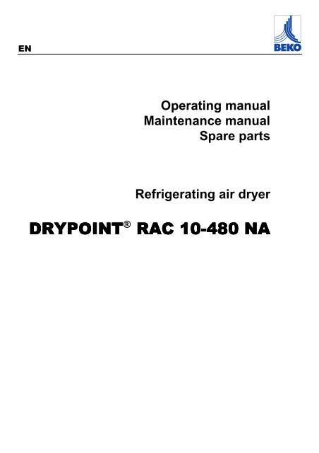
ENOperating <strong>manual</strong>Maint<strong>en</strong>ance <strong>manual</strong>Spare partsRefrigerating air dryer<strong>DRYPOINT</strong> ® <strong>RAC</strong> <strong>10</strong>-48<strong>480</strong> <strong>NA</strong>
Dear Customer,thank you for choosing our product. In order to get the best performances out of this product, please read this <strong>manual</strong>carefully.To avoid incorrect operation of the equipm<strong>en</strong>t and possible physical risk to the operator, please read and strictly followthe instructions contained in this <strong>manual</strong>.Note, these instructions are in addition to the safety rules that apply in the country where the dryer is installed. Beforepacking for shipm<strong>en</strong>t each <strong>DRYPOINT</strong> <strong>RAC</strong> <strong>NA</strong> series refrigerated air dryer undergoes a rigorous test to <strong>en</strong>sure theabs<strong>en</strong>ce of any manufacturing faults and to demonstrate that the device can perform all the functions for which it hasbe<strong>en</strong> designed.Once the dryer has be<strong>en</strong> properly installed according to the instructions in this <strong>manual</strong>, it will be ready for use withoutany further adjustm<strong>en</strong>t. The operation is fully automatic, and the maint<strong>en</strong>ance is limited to few controls and somecleaning operations, as detailed in the following chapters.This <strong>manual</strong> must be maintained available in any mom<strong>en</strong>t for future refer<strong>en</strong>ces and it has to be int<strong>en</strong>ded as inher<strong>en</strong>tpart of the relevant dryer.Due to the continuous technical evolution, we reserve the right to introduce any necessary change without givingprevious notice.Should you experi<strong>en</strong>ce any trouble, or for further information, please do not hesitate to contact us.DATA <strong>NA</strong>MEPLATEThe data nameplate is located on the back of the dryer and shows all the primary data of the machine. This data shouldalways be referred to wh<strong>en</strong> calling the manufacturer or distributor. The removal or alteration of the data nameplate willvoid the warranty rights.2 <strong>DRYPOINT</strong> <strong>RAC</strong> <strong>10</strong> – <strong>480</strong> <strong>NA</strong>
Index7.3.3. Electrical Diagram <strong>DRYPOINT</strong> <strong>RAC</strong> <strong>10</strong>-<strong>10</strong>0 <strong>NA</strong> -E (230/1/60)................................................................... 417.3.4. Electrical Diagram <strong>DRYPOINT</strong> <strong>RAC</strong> 125-175 <strong>NA</strong> -P (115/1/60)................................................................. 427.3.5. Electrical Diagram <strong>DRYPOINT</strong> <strong>RAC</strong> 125-150 <strong>NA</strong> -E (230/1/60)................................................................. 427.3.6. Electrical Diagram <strong>DRYPOINT</strong> <strong>RAC</strong> 175-220 <strong>NA</strong> -E (230/1/60)................................................................. 427.3.7. Electrical Diagram <strong>DRYPOINT</strong> <strong>RAC</strong> 300-375 <strong>NA</strong> -E (230/1/60)................................................................. 437.3.8. Electrical Diagram <strong>DRYPOINT</strong> <strong>RAC</strong> <strong>480</strong> <strong>NA</strong> -E (230/1/60) ........................................................................ 434 <strong>DRYPOINT</strong> <strong>RAC</strong> <strong>10</strong> – <strong>480</strong> <strong>NA</strong>
Safety rules1. Safety rules1.1. Definition of the Conv<strong>en</strong>tional Signs Used in This ManualCarefully read instruction <strong>manual</strong> before attempting any service or maint<strong>en</strong>ance procedures on the dryer.Caution warning sign. Risk of danger or possibility of damage to equipm<strong>en</strong>t, if related text is not followedproperly.Electrical hazard. Warning message indicates practices or procedures that could result in personal injury orfatality if not followed correctly.Danger hazard. Part or system under pressure.Danger hazard. High temperature conditions exist during operation of system. Avoid contact until system orcompon<strong>en</strong>t has dissipated heat.Danger hazard. Treated air is not suitable for breathing purposes; serious injury or fatality may result ifprecautions are not followed.Danger hazard: In case of fire, use an approved fire extinguisher, water is not an acceptable means in casesof fire.Danger hazard. Do not operate equipm<strong>en</strong>t with panels removed.Maint<strong>en</strong>ance or control operation to be performed by qualified personnel only 1 .ARIAAIRLUFTAIRCompressed air inlet connection pointARIAAIRLUFTAIRCompressed air outlet connection pointCond<strong>en</strong>sate drain connection pointOperations which can be performed by the operator of the machine, if qualified 1.NOTE: Text that specifies items of note to be tak<strong>en</strong> into account does not involve safety precautions.1In designing this unit a lot of care has be<strong>en</strong> devoted to <strong>en</strong>vironm<strong>en</strong>tal protection:• CFC free refrigerants• CFC free insulation parts• Energy saving design• Limited acoustic emission• Dryer and relevant packaging composed of recyclable materialsThis symbol requests that the user heed <strong>en</strong>vironm<strong>en</strong>tal considerations and abide with suggestions annotatedwith this symbol.Experi<strong>en</strong>ced and trained personnel familiar with national and local codes, capable to perform the needed activities, id<strong>en</strong>tify and avoid possibledangerous situations while handling, installing, using and servicing the machine. Ensuring compliance to all statutory regulations.<strong>DRYPOINT</strong> <strong>RAC</strong> <strong>10</strong> – <strong>480</strong> <strong>NA</strong> 5
Safety rules1.2. WarningsDANGER!Compressed air!Compressed air is a highly hazardous <strong>en</strong>ergy source.Never work on the dryer with pressure in the system.Never point the compressed air or the cond<strong>en</strong>sate drain outlet hoses towards anybody.The user is responsible for the proper installation of the dryer. Failure to follow instructions giv<strong>en</strong> in the“Installation” chapter will void the warranty. Improper installation can create dangerous situations for personneland/or damages to the machine could occur.DANGER!Mains voltage!Only qualified personnel are authorized to service electrically powered devices. Before attemptingmaint<strong>en</strong>ance, the following conditions must be satisfied:Ensure that main power is off, machine is locked out, tagged for service and power cannot be restored duringservice operations.Ensure that valves are shut and the air circuit is at atmospheric pressure. De-pressurize the dryer.CAUTION!Refrigerant!These refrigerating air dryers contain R134a or R404A HFC type refrigerant fluid. Refer to the specificparagraph - maint<strong>en</strong>ance operation on the refrigerating circuit.WARNING!Unauthorized interfer<strong>en</strong>ce!Warranty does not apply to any unit damaged by accid<strong>en</strong>t, modification, misuse, neglig<strong>en</strong>ce or misapplication.Unauthorized alterations will immediately void the warranty.In case of fire, use an approved fire extinguisher, water is not an acceptable means in cases of electrical fire.1.3. Proper Use of the DryerThis dryer has be<strong>en</strong> designed, manufactured and tested for the purpose of separating the humidity normally containedin compressed air. Any other use has to be considered improper.The Manufacturer will not be responsible for any problem arising from improper use; the user will bear responsibility forany resulting damage.Moreover, the correct use requires the adher<strong>en</strong>ce to the installation instructions, specifically:• Voltage and frequ<strong>en</strong>cy of the main power.• Pressure, temperature and flow-rate of the inlet air.• Ambi<strong>en</strong>t temperature.This dryer is supplied tested and fully assembled. The only operation left to the user is the connection to the plant incompliance with the instructions giv<strong>en</strong> in the following chapters.WARNING!Improper use!The purpose of the machine is the separation of water and ev<strong>en</strong>tual oil particles pres<strong>en</strong>t in compressed air.The dried air cannot be used for breathing purposes or for operations leading to direct contact with foodstuff.This dryer is not suitable for the treatm<strong>en</strong>t of dirty air or of air containing solid particles.6 <strong>DRYPOINT</strong> <strong>RAC</strong> <strong>10</strong> – <strong>480</strong> <strong>NA</strong>
Installation1.4. Instructions for the use of pressure equipm<strong>en</strong>t according to PED Directive 97/23/ECTo <strong>en</strong>sure the safe operation of pressure equipm<strong>en</strong>ts, the user must conform strictly to the above directive and thefollowing:1. The equipm<strong>en</strong>t must only be operated within the temperature and pressure limits stated on the manufacturer’sdata nameplate.2. Welding on heat-exchanger is not recomm<strong>en</strong>ded.3. The equipm<strong>en</strong>t must not be stored in badly v<strong>en</strong>tilated spaces, near a heat source or inflammable substances.4. Vibration must be eliminated from the equipm<strong>en</strong>t to prev<strong>en</strong>t fatigue failure.5. Automatic cond<strong>en</strong>sate drains should be checked for operation every day to prev<strong>en</strong>t a build up of cond<strong>en</strong>sate in thepressure equipm<strong>en</strong>t.6. The maximum working pressure stated on the manufacturer’s data nameplate must not be exceeded. Prior to use,the user must fit safety / pressure relief devices.7. All docum<strong>en</strong>tation supplied with the equipm<strong>en</strong>t (<strong>manual</strong>, declaration of conformity etc.) must be kept for futurerefer<strong>en</strong>ce.8. Do not apply weights or external loads on the vessel or its connecting piping.2. InstallationWARNING!Unauthorized interfer<strong>en</strong>ce!Users of the equipm<strong>en</strong>t must comply with all local and national pressure equipm<strong>en</strong>t legislation in the countryof installation.2.1. TransportCheck for visible loss or damage, if no visible damage is found place the unit near to the installation point and unpackthe cont<strong>en</strong>ts.• Always keep the dryer in the upright vertical position. Damage to compon<strong>en</strong>ts could result if unit is laid on its side orif placed upside down.• Store machine in a clean, dry <strong>en</strong>vironm<strong>en</strong>t, do not expose to severe weather <strong>en</strong>vironm<strong>en</strong>ts.• Handle with care. Heavy blows could cause irreparable damage.2.2. StorageEv<strong>en</strong> wh<strong>en</strong> packaged, keep the machine protectedfrom severity of the weather.Keep the dryer in vertical position, also wh<strong>en</strong> stored.Turning it upside down some parts could beirreparably damaged.If not in use, the dryer can be stored in its packaging ina dust free and protected site at a maximumtemperature of 115°F (45°C), and a specific humidit ynot exceeding 90%. Should the stocking time exceed12 months, please contact the manufacturer.SCC00<strong>01</strong>The packaging materials are recyclable. Dispose of material in compliance with the rules andregulations in force in the destination country.<strong>DRYPOINT</strong> <strong>RAC</strong> <strong>10</strong> – <strong>480</strong> <strong>NA</strong> 7
Installation2.3. Installation siteCAUTION!Ambi<strong>en</strong>t conditions!Failure to install dryer in the proper ambi<strong>en</strong>t conditions will affect the dryer’s ability to cond<strong>en</strong>se refrigerantgas. This can cause higher loads on the compressor, loss of dryer effici<strong>en</strong>cy and performance, overheatedcond<strong>en</strong>ser fan motors, electrical compon<strong>en</strong>t failure and dryer failure due to the following: compressor loss,fan motor failure and electrical compon<strong>en</strong>t failure. Failures of this type will affect warranty considerations.Do not install dryer in an <strong>en</strong>vironm<strong>en</strong>t of corrosive chemicals, explosive gasses, poisonous gasses; steamheat, areas of high ambi<strong>en</strong>t conditions or extreme dust and dirt.In case of fire, use an approved fire extinguisher,water is not an acceptable means in cases offire.Minimum installation requirem<strong>en</strong>ts:• Select a clean room dry, free from dust, and protectedfrom atmospheric disturbances.• The supporting area must be smooth, horizontal andable to hold the weight of the dryer.• Minimum ambi<strong>en</strong>t temperature +34 °F (+1 °C).• Maximum ambi<strong>en</strong>t temperature +115 °F (+45 °C).• Leave at least 40 in (1m) of free space on every side ofthe drier for v<strong>en</strong>tilation purposes and maint<strong>en</strong>anceoperations.The dryer doesn't require to be fixed to the supportingsurface. The dryer needs to be fixed to the supportingsurface only with particular installation procedures (dryeron brakets, hanging units, etc.)Dryer hanging:Dryer A [in-mm] B [in-mm] C [in-mm] D [in-mm]<strong>DRYPOINT</strong> <strong>RAC</strong> <strong>10</strong>-15 <strong>NA</strong> 3/4"- 20 12 - 305 3/4"- 20 1.1/4" - 33<strong>DRYPOINT</strong> <strong>RAC</strong> 20-50 <strong>NA</strong> 1"- 25 18.5/16"- 465 1"- 25 13/16" - 30<strong>DRYPOINT</strong> <strong>RAC</strong> 75 <strong>NA</strong> 1.9/16"- 40 14.3/16"- 360 3/4"- 20 13/16" - 30<strong>DRYPOINT</strong> <strong>RAC</strong> <strong>10</strong>0 <strong>NA</strong> 1.9/16"- 40 15,3/16"- 385 3/4"- 20 13/16" - 308 <strong>DRYPOINT</strong> <strong>RAC</strong> <strong>10</strong> – <strong>480</strong> <strong>NA</strong>
Installation2.4. Installation layout- A -7IN1 Air compressor2 Aftercooler3 48OUT53Cond<strong>en</strong>sate separator14Pre-Filter (min. 5 micron)5By-pass group29 99966 Dryer7 Compressed air tank- B -IN789Final filter<strong>Beko</strong>mat cond<strong>en</strong>sate drain134OUT5 8299699CAUTION!Polluted inlet air!In case of heavily polluted inlet air (ISO 8573.1 class 3.-.3 or worse quality), we recomm<strong>en</strong>d the additionalinstallation of a pre-filter (f.e. CLEARPOINT F040) to prev<strong>en</strong>t a clogging of the heat exchangerType A installation is suggested wh<strong>en</strong> the compressor operates at reduced intermitt<strong>en</strong>ce and the total consumptionequals the compressor flow rate.Type B installation is suggested wh<strong>en</strong> the air consumption can consist<strong>en</strong>tly change with peak values highly exceedingthe flow rate of the compressor. The capacity of the tank must be sized in order to comp<strong>en</strong>sate ev<strong>en</strong>tual instantaneousdemand conditions (peak air consumption).<strong>DRYPOINT</strong> <strong>RAC</strong> <strong>10</strong> – <strong>480</strong> <strong>NA</strong> 9
Installation2.5. Correction factorsCorrection factor for operating pressure changes :Inlet air pressure psig 60 80 <strong>10</strong>0 120 140 160 180 203barg 4 5.5 7 8 <strong>10</strong> 11 12 14Factor (F1) 0.79 0.91 1.00 1.07 1.13 1.18 1.23 1.27Correction factor for ambi<strong>en</strong>t temperature changes (Air-Cooled):Ambi<strong>en</strong>t temperature ºF 80 90 95 <strong>10</strong>0 <strong>10</strong>5 1<strong>10</strong> 113ºC 27 32 35 38 40 43 45Factor (F2) 1.<strong>10</strong> 1.07 1.04 1.00 0.93 0.83 0.70Correction factor for inlet air temperature changes:Air temperature ºF 90 <strong>10</strong>0 1<strong>10</strong> 120 131ºC 32 38 43 50 55Factor (F3) 1.11 1.00 0.80 0.65 0.53Correction factor for DewPoint changes:DewPoint ºF 38 41 45 50ºC 3 5 7 <strong>10</strong>Factor (F4) 0.92 1.00 1.07 1.25How to find the air flow capacity:How to select a suitable dryer for a giv<strong>en</strong> duty:Air flowcapacity =NominalX Factor(F1)FactorX(F2)FactorX(F3)X Factor(F4)MinimumDesigndutyStd. air = ÷ Factor(F1)flow rateair flow÷Factor(F2)Factor÷ (F3) ÷ Factor(F4)Example:An <strong>DRYPOINT</strong> <strong>RAC</strong> 75 <strong>NA</strong> has a nominal duty of 75scfm (127 m 3 /h). What is the maximum allowable flowthrough the dryer under the following operatingconditions:– Inlet air pressure = 120 psig (8 barg)– Ambi<strong>en</strong>t temperature = 90°F (32°C)– Inlet air temperature = 1<strong>10</strong>°F (43°C)Example:The procedure here is to list the operating conditions andth<strong>en</strong> to locate the corresponding numerical factors:– Design air flow = 60 scfm (<strong>10</strong>2 m 3 /h)– Inlet air pressure = 120 psig (8 barg)– Ambi<strong>en</strong>t temperature = 90°F (32°C)– Inlet air temperature = 1<strong>10</strong>°F (43°C)– Pressure DewPoint = 41°F (5°C)Each item of data has a corresponding numerical factoras follows:75 1.07 1.07 0.80 1.00– Pressure DewPoint = 41°F (5°C)In order to select the correct dryer model the required flowrate is to be divided by the correction factors relating toabove m<strong>en</strong>tioned parameters:Minimum60 1.07 1.07 0.80 1.00Air flowcapacity = x x x x= ÷ ÷ ÷ ÷flow rate= 69 scfm (117 m 3 /h)→This is the maximumflow rate that the dryer can accept under these operatingconditions.= 66 scfm (112 m 3 /h) → Therefore the modelsuitable for the conditions above is <strong>DRYPOINT</strong> <strong>RAC</strong> 75<strong>NA</strong> (75 scfm or 127 m3/h - nominal duty).<strong>10</strong> <strong>DRYPOINT</strong> <strong>RAC</strong> <strong>10</strong> – <strong>480</strong> <strong>NA</strong>
2.6. Connection to the Compressed Air SystemInstallationDANGER!Compressed air!Operations to be performed by qualified personnel only.Never work on compressed air system under pressure.The user is responsible to <strong>en</strong>sure that the dryer will never be operated with pressure exceeding the maximumpressure rating on the unit data tag.Over-pressurizing the dryer could be dangerous for both the operator and the unit.The air temperature and the flow <strong>en</strong>tering the dryer must comply within the limits stated on the data nameplate. Thesystem connecting piping must be kept free from dust, rust, chips and other impurities, and must be consist<strong>en</strong>t with theflow-rate of the dryer. In case of treatm<strong>en</strong>t of air at particularly high temperature, the installation of a final refrigeratorcould result necessary. In order to perform maint<strong>en</strong>ance operations, it recomm<strong>en</strong>ded that a dryer by-pass system beinstalled as shown in the following illustration.BPY00<strong>01</strong>ØDryer Ø [NPT-F] A [in - mm]<strong>DRYPOINT</strong> <strong>RAC</strong> <strong>10</strong>-15 <strong>NA</strong> 3/8” 1.5/8” – 40<strong>DRYPOINT</strong> <strong>RAC</strong> 20-50 <strong>NA</strong> 1/2” 8.1/4” – 2<strong>10</strong><strong>DRYPOINT</strong> <strong>RAC</strong> 75 <strong>NA</strong> 1” 8” – 205<strong>DRYPOINT</strong> <strong>RAC</strong> <strong>10</strong>0-150 <strong>NA</strong> 1.1/4” 8” – 205<strong>DRYPOINT</strong> <strong>RAC</strong> 175-220 <strong>NA</strong> 1.1/2” 9.1/4” – 235<strong>DRYPOINT</strong> <strong>RAC</strong> 300-375 <strong>NA</strong> 2” 13.1/2” – 345<strong>DRYPOINT</strong> <strong>RAC</strong> <strong>480</strong> <strong>NA</strong> 2.1/2” 16.1/8” – 4<strong>10</strong>In realising the dryer, particular measures have be<strong>en</strong> tak<strong>en</strong> in order to limit the vibration which could occur during theoperation. Therefore we recomm<strong>en</strong>d to use connecting pipes able to insulate the dryer from possible vibrationsoriginating from the line (flexible hoses, vibration damping fittings, etc.).CAUTION:Piping the dryer, inlet/outlet connections must be supported as show in the diagram.Failing will result in damage.<strong>DRYPOINT</strong> <strong>RAC</strong> <strong>10</strong> – <strong>480</strong> <strong>NA</strong> 11
Start up2.7. Electrical connectionsDANGER!Supply voltage!Qualified personnel should carry out connecting unit to the main power.Be sure to check the local codes in your area.Before connecting the unit to the electrical supply, verify the id<strong>en</strong>tification plate for the proper electrical information.Voltage tolerance is +/- 5%.Dryer supplied at 115/1/60 voltage comes with a mains connecting cable already installed and <strong>en</strong>ding with a North-American standard plug 2 poles + ground. Dryer supplied at 230/1/60 voltages comes with a box for the connection tothe mains.Be sure to provide the proper fuses or breakers based on the data information located on the nameplate.The mains socket must be provided with a mains magneto-thermal differ<strong>en</strong>tial breaker (I∆n=0.03A), adjusted on thebasis of the consumption of the dryer (see the nominal values on the data plate of the dryer). The cross section of thepower supply cables must comply with the consumption of the dryer, while keeping into account also the ambi<strong>en</strong>ttemperature, the conditions of the mains installation, the l<strong>en</strong>gth of the cables, and the requirem<strong>en</strong>ts <strong>en</strong>forced by thelocal Power Provider.DANGER!Mains voltage and missing earthing!Important: <strong>en</strong>sure that the plant is earthed.Do not use any socket adapters at the mains plug.If the mains plug needs to be replaced, this must only be done by a qualified electrician2.8. Cond<strong>en</strong>sate DrainDANGER!Compressed air and pressurized cond<strong>en</strong>sate!The cond<strong>en</strong>sate is discharge at the system pressure.Drain line should be secured.Never point the cond<strong>en</strong>sate drain line towards anybody.Timed drainThe cond<strong>en</strong>sate drain occurs through a sol<strong>en</strong>oid valve protected with a mechanical strainer. The sol<strong>en</strong>oid valve coil isoperated by electronic instrum<strong>en</strong>t.BEKOMAT drainThe dryer comes already fitted with an electronically level controlled BEKOMAT cond<strong>en</strong>sate drain.Connect and properly fast<strong>en</strong> the cond<strong>en</strong>sate drain to a collecting plant or container.The drain cannot be connected to pressurized systems.3. Start upDon’t dispose the cond<strong>en</strong>sate in the <strong>en</strong>vironm<strong>en</strong>t.The cond<strong>en</strong>sate collected in the dryer contains oil particles released in the air by the compressor.Dispose the cond<strong>en</strong>sate in compliance with the local rules.We suggest to install a water-oil separator where to convey all the cond<strong>en</strong>sate drain coming fromcompressors, dryers, tanks, filters, etc. We recomm<strong>en</strong>d ÖWAMAT oil-water separators for dispersecompressor cond<strong>en</strong>sate, BEKOSPLIT emulsion splitters for emulsified cond<strong>en</strong>sate.3.1. Preliminary OperationsCAUTION!Exceeding of operating parameters!Verify that the operating parameters match with the nominal values stated on the data nameplate of the dryer(voltage, frequ<strong>en</strong>cy, air pressure, air temperature, ambi<strong>en</strong>t temperature, etc.).This dryer has be<strong>en</strong> thoroughly tested, packaged and inspected prior to shipm<strong>en</strong>t. Nevertheless, the unit could bedamaged during transportation, check the integrity of the dryer during first start-up and monitor operation during the firsthours of operation.Qualified personnel must perform the first start-up.Wh<strong>en</strong> installing and operating this equipm<strong>en</strong>t, comply with all National Electrical Code and any applicablefederal, state and local codes.Who is operating the unit is responsible for the proper and safe operation of the dryer.Never operate equipm<strong>en</strong>t with panels removed.12 <strong>DRYPOINT</strong> <strong>RAC</strong> <strong>10</strong> – <strong>480</strong> <strong>NA</strong>
3.2. First start-upStart upThis procedure should be followed on first start-up, after periods of ext<strong>en</strong>ded shutdown or followingmaint<strong>en</strong>ance procedures.Qualified personnel must perform the start-up.Sequ<strong>en</strong>ce of operations (refer to paragraph 5.1 Control Panel).• Ensure that all the steps of the “Installation” chapter have be<strong>en</strong> observed.• Ensure that the connection to the compressed air system is correct and that the piping is suitably fixed andsupported.• Ensure that the cond<strong>en</strong>sate drain pipe is properly fast<strong>en</strong>ed and connected to a collection system or container.• Ensure that the by-pass system (if installed) is op<strong>en</strong> and the dryer is isolated• Ensure that the <strong>manual</strong> valve of the cond<strong>en</strong>sate drain circuit is op<strong>en</strong>.• Remove any packaging and other material which could obstruct the area around the dryer.• Activate the mains switch.• Turn on the main switch - pos. 1 on the control panel.• Ensure that the DMC15 electronic instrum<strong>en</strong>t is ON.• Ensure the consumption matches with the values of the data plate.• Ensure the fan work properly - wait for its first interv<strong>en</strong>tions.• Allow the dryer temperature to stabilise at the pre-set value.• Slowly op<strong>en</strong> the air inlet valve.• Slowly op<strong>en</strong> the air outlet valve.• Slowly close the c<strong>en</strong>tral by-pass valve of the system (if installed).• Check the piping for air leakage.• Ensure the drain is regularly cycling - wait for its first interv<strong>en</strong>tions.3.3. Start-up and shut downStart-up (refer to paragraph 5.1 Control Panel)• Check the cond<strong>en</strong>ser for cleanliness.• Verify that the system is powered.• Turn on the main switch - pos. 1 on the control panel.• Ensure that DMC15 electronic instrum<strong>en</strong>t is ON.• Wait a few minutes; verify that the DewPoint temperature displayed on DMC15 electronic instrum<strong>en</strong>t is correct andthat the cond<strong>en</strong>sate is regularly drained.• Switch on the air compressor.Shut down (refer to paragraph 5.1 Control Panel)• Verify that the DewPoint temperature displayed on electronic controller DMC15 is correct.• Shut down the air compressor.• After a few minutes, Shut down the dryer using the main switch on the control panel (pos. 1).NOTE : A DewPoint included in the gre<strong>en</strong> operating area of the electronic controller is correct accordingto the possible working conditions (flow-rate, temperature of the incoming air, ambi<strong>en</strong>t temperature,etc.)During the operation, the refrigerating compressor will run continuously. The dryer must remain on during the fullusage period of the compressed air, ev<strong>en</strong> if the air compressor works intermitt<strong>en</strong>tly.The number of starts must be no more than 6 per hour. The dryer must stop running for at least 5minutes before being started up again.The user is responsible for compliance with these rules. Frequ<strong>en</strong>t starts may cause irreparable damage.<strong>DRYPOINT</strong> <strong>RAC</strong> <strong>10</strong> – <strong>480</strong> <strong>NA</strong> 13
Technical Specifications4. Technical Specifications4.1. Technical Specifications <strong>DRYPOINT</strong> <strong>RAC</strong> <strong>10</strong>-<strong>10</strong>0 <strong>NA</strong> -P14 <strong>DRYPOINT</strong> <strong>RAC</strong> <strong>10</strong> – <strong>480</strong> <strong>NA</strong>
Technical Specifications4.2. Technical Specifications <strong>DRYPOINT</strong> <strong>RAC</strong> <strong>10</strong>-<strong>10</strong>0 <strong>NA</strong> -E<strong>DRYPOINT</strong> <strong>RAC</strong> <strong>10</strong> – <strong>480</strong> <strong>NA</strong> 15
Technical Specifications4.3. Technical Specifications <strong>DRYPOINT</strong> <strong>RAC</strong> 125-<strong>480</strong> <strong>NA</strong> -P / -E16 <strong>DRYPOINT</strong> <strong>RAC</strong> <strong>10</strong> – <strong>480</strong> <strong>NA</strong>
Technical description5. Technical description5.1. Control panelThe control panel illustrated below is the only dryer-operator interface.<strong>RAC</strong> <strong>10</strong>-150 <strong>NA</strong>K<strong>10</strong>sec - minONDMC15PQS00081set2 3<strong>RAC</strong> 175-<strong>480</strong> <strong>NA</strong>IONKONDMC15sec - minsetPQS00241 231 Main switch 3 Air and refrigerating gas flow diagram2 DMC15 Electronic control instrum<strong>en</strong>t5.2. OperationOperating principal - The dryer models described in this <strong>manual</strong> operate all on the same principal. The hot moisture lad<strong>en</strong> air<strong>en</strong>ters an air to air heat exchanger. The air th<strong>en</strong> goes through the evaporator, also known as the air to refrigerant heatexchanger. The temperature of the air is reduced to approximately 36°F (2°C), causing water vapor to c ond<strong>en</strong>se to liquid. Theliquid is continuously coalesced and collected in the separator for removal by the cond<strong>en</strong>sate drain. The cool moisture free airth<strong>en</strong> passes back through the air to air heat exchanger to be reheated to within 8 degrees of the incoming air temperature as itexits the dryer.Refrigerant circuit - Refrigerant gas is cycled through the compressor and exits at high pressure to a cond<strong>en</strong>ser whereheat is removed causing the refrigerant to cond<strong>en</strong>se to a high-pressure liquid state. The liquid is forced through acapillary tube where the resulting pressure drop allows the refrigerant to boil off at a predetermined temperature. Lowpressureliquid refrigerant <strong>en</strong>ters the heat exchanger where heat from the incoming air is transferred causing therefrigerant to boil; the resulting phase change produces a low pressure, low temperature gas. The low-pressure gas isreturned to the compressor, where it is re-compressed and begins the cycle again. During those periods wh<strong>en</strong> thecompressed air load is reduced the excess refrigerant is by-passed automatically back to the compressor via the HotGas By-pass Valve circuit.<strong>DRYPOINT</strong> <strong>RAC</strong> <strong>10</strong> – <strong>480</strong> <strong>NA</strong> 17
Technical description5.3. Flow Diagram2345P BT SPAPV61a11b717 EC9M8T1121c12.111<strong>10</strong>T2DGF000415StandardTimed13 1416ECELD21<strong>Beko</strong>mat Optional1 Alu-Dry Module 9 Cond<strong>en</strong>ser fana - Air-to-air heat exchanger <strong>10</strong> Filter drierb - Air-to-refrigerant exchanger 11 Capillary tubec - Cond<strong>en</strong>sate separator 12 T1 Temperature probe (DewPoint)2 Refrigerant pressure-switch PB (<strong>RAC</strong> <strong>480</strong>) 12.1 T2 Temperature probe (fan control) (<strong>RAC</strong> <strong>10</strong>-<strong>10</strong>0)3 Safety thermo-switch TS (<strong>RAC</strong> 125-<strong>480</strong>) 13 Cond<strong>en</strong>sate drain isolation valve4 Refrigerant pressure-switch PA (<strong>RAC</strong> 300-<strong>480</strong>) 14 Cond<strong>en</strong>sate drain strainer5 Refrigerant Fan pressure-switch PV (<strong>RAC</strong> 125-<strong>480</strong>) 15 Cond<strong>en</strong>sate drain sol<strong>en</strong>oid valve6 Refrigeration compressor 16 Coil for cond. drain sol<strong>en</strong>oid valve7 Hot gas by-pass valve 17 Air Dryer Controller8 Cond<strong>en</strong>ser 21 <strong>Beko</strong>mat drainCompressed air flow directionRefrigerating gas flow direction18 <strong>DRYPOINT</strong> <strong>RAC</strong> <strong>10</strong> – <strong>480</strong> <strong>NA</strong>
5.4. Refrigerating compressorTechnical descriptionThe refrigerating compressor is the pump in the system, gas coming from the evaporator (low pressure side) iscompressed up to the cond<strong>en</strong>sation pressure (high pressure side). The compressors utilized are manufactured byleading manufacturers and are designed for applications where high compression ratios and wide temperature changesare pres<strong>en</strong>t.The hermetically sealed construction is perfectly gas tight, <strong>en</strong>suring high-<strong>en</strong>ergy effici<strong>en</strong>cy and long, useful life.Dumping springs support the pumping unit in order to reduce the acoustic emission and the vibration diffusion. Theaspirated refrigerating gas, flowing through the coils before reaching the compression cylinders cools the electricmotor. The thermal protection protects the compressor from over heating and over curr<strong>en</strong>ts. The protection isautomatically restored as soon as the nominal temperature conditions are reached.5.5. Cond<strong>en</strong>serThe cond<strong>en</strong>ser is the compon<strong>en</strong>t in which the gas coming from the compressor is cooled down and cond<strong>en</strong>sedbecoming a liquid. Mechanically, a serp<strong>en</strong>tine copper tubing circuit (with the gas flowing inside) is <strong>en</strong>capsulated in analuminum fin package.The cooling operation occurs via a high effici<strong>en</strong>cy fan, creating airflow within the dryer, moving air through the finpackage. It’s mandatory that the ambi<strong>en</strong>t air temperature does not exceed the nominal values. It is also important tokeep the cond<strong>en</strong>ser unit free from dust and other impurities.5.6. Filter DrierTraces of humidity and slag can accumulate inside the refrigerating circuit. Long periods of use can also producesludge. This can limit the lubrication effici<strong>en</strong>cy of the compressor and clog the expansion valve or capillary tube. Thefunction of the Filter Drier, located before the capillary tubing, is to eliminate any impurities from circulating through thesystem.5.7. Capillary TubeIt consists of a piece of reduced cross section copper tubing located betwe<strong>en</strong> the cond<strong>en</strong>ser and the evaporator, actingas a metering device to reduce the pressure of the refrigerant. Reduction of pressure is a design function to achieveoptimum temperature reached within the evaporator: the smaller the capillary tube outlet pressure, the lower theevaporation temperature.The l<strong>en</strong>gth and interior diameter of the capillary tubing is accurately sized to establish the performance of the dryer; nomaint<strong>en</strong>ance or adjustm<strong>en</strong>t is necessary.5.8. Alu-Dry ModuleThe heat exchanger module houses the air-to-air, the air-to-refrigerant heat exchangers and the demister typecond<strong>en</strong>sate separator. The counter flow of compressed air in the air-to-air heat exchanger <strong>en</strong>sures maximum heattransfer. The g<strong>en</strong>erous cross section of flow channel within the heat exchanger module leads to low velocities andreduced power requirem<strong>en</strong>ts. The g<strong>en</strong>erous dim<strong>en</strong>sions of the air-to-refrigerant heat exchanger plus the counter flowgas flow allows full and complete evaporation of the refrigerant (prev<strong>en</strong>ting liquid return to the compressor). The higheffici<strong>en</strong>cy cond<strong>en</strong>sate separator is located within the heat exchanger module. No maint<strong>en</strong>ance is required and thecoalescing effect results in a high degree of moisture separation.<strong>DRYPOINT</strong> <strong>RAC</strong> <strong>10</strong> – <strong>480</strong> <strong>NA</strong> 19
Technical description5.9. Hot Gas By-pass ValveThis valve injects part of the hot gas (tak<strong>en</strong> from the discharge side of the compressor) in the pipe betwe<strong>en</strong> theevaporator and the suction side of the compressor, keeping the evaporation temperature/pressure constant at approx.36°F (+2 °C). This injection prev<strong>en</strong>ts the formation of ice inside the dryer evaporator at every load condition.ADJUSTMENTThe Hot Gas By-pass Valve is adjusted during the manufacturing testingphase. As a rule no adjustm<strong>en</strong>t is required; anyway if it is necessary theoperation must be carried out by an experi<strong>en</strong>ced refrigeration <strong>en</strong>gineer.WARNING : the use of ¼” Schrader service valves must be justified by a realmalfunction of the refrigeration system. Each time a pressure gauge isconnected, a part of refrigerant is exhausted.Without compressed air flow through the dryer, rotate the adjusting screw(position A on the drawing) until the following value is reached:Hot gas setting (R134.a) : temperature 33°F (+1 / -0 °F)pressure 29 psig (+1.5 / -0 psi)temperature 0.5°C (+0.5 / -0 °K)pressure 2.0 barg (+0.1 / -0 bar)VLY00<strong>01</strong>-+A4 mm5/32 in.Hot gas setting (R404A) :temperature 33°F (+1 / - 0 °F)pressure 75.4 psig (+1.5 / -0 psi)temperature 0.5°C (+0.5 / -0 °K)pressure 5.2 barg (+0.1 / -0 bar)5.<strong>10</strong>. Refrigerant Pressure Switches PA – PB – PVAs operation safety and protection of the dryer a series of pressure switches are installed in gas circuit.PB :PA :PV :Low-pressure controller device on the pushing side (carter) of the compressor, is <strong>en</strong>abled only if the pressuredrops below the pre-set value. The values are automatically reset wh<strong>en</strong> the nominal conditions are restored.Calibrated pressure : R 404 A Stop 14.5 psig - Restart 72.5 psigR 404 AStop 1.0 barg - Restart 5.0 bargThis high-pressure controller device, located on the pushing side on the compressor, is activated wh<strong>en</strong> thepressure exceeds the pre-set value. It features a <strong>manual</strong>-resetting button mounted on the controller itself.Calibrated pressure : R 404 A Stop 464 psig - Manual resetR 404 AStop 32 barg - Manual resetFan control pressure switch is placed at the discharge side of refrigeration compressor. It keeps thecond<strong>en</strong>sation temperature/pressure constant within preset limits (Air-Cooled).Calibrated pressure : R 404 A Start 290 psig (113°F) - Stop 232 psig (97°F) - Tol erance ± 15 psiR 404 AStart 20 barg (45°C) - Stop 16 barg (36°C) - Tolera nce ± 1 bar5.11. Safety Thermo-Switch TSPQS000512To protect the operating safety and the integrity of the dryer, a thermo-switch (TS)is installed on the refrigerant gas circuit. The thermo-switch s<strong>en</strong>sor, in case ofunusual discharge temperatures, stops the refrigerating compressor before it isperman<strong>en</strong>tly damaged.Manually reset the thermo-switch only after the nominal operating conditions havebe<strong>en</strong> restored. Unscrew the relative cap (see pos.1 in the figure) and press thereset button (see pos.2 in the figure).TS setting : temperature 212 °F (+4 / -4 °F)temperature <strong>10</strong>0 °C (+2 / -2 °K)20 <strong>DRYPOINT</strong> <strong>RAC</strong> <strong>10</strong> – <strong>480</strong> <strong>NA</strong>
5.12. DMC15 Electronic Instrum<strong>en</strong>t (Air Dryer Controller)setsec - minONDMC 15set Button - access the set-up.ButtonTechnical description- cond<strong>en</strong>sate drain test / value increm<strong>en</strong>t.Gre<strong>en</strong> LED - glowing = power on.Yellow LED - glowing = cond<strong>en</strong>sate drain sol<strong>en</strong>oid valve ontimed drain onlyYellow LED - glowing = cond<strong>en</strong>ser fan on.DISPLAYThe DMC15 electronic controller performs the following functions : it shows the curr<strong>en</strong>t operating DewPoint through thedigital led display which is detected from the (T1) probe located at the <strong>en</strong>d of the evaporator, while a second (T2) probe,located on the discharge side of the cond<strong>en</strong>ser, activates the relevant fan (<strong>RAC</strong> <strong>10</strong>-<strong>10</strong>0 only); ev<strong>en</strong>tually it controls thefunctioning of cond<strong>en</strong>sate drain sol<strong>en</strong>oid valve through the cyclic electronic timer (timed drain only).OPERATION - During the dryer operation, the LEDThermometer - The <strong>10</strong> LED display indicates the curr<strong>en</strong>t operating DewPoint, shown by means of a two colours(gre<strong>en</strong> - red) bar over the display itself.• Gre<strong>en</strong> section - operating conditions <strong>en</strong>suring an optimal DewPoint;• Red section - DewPoint of the dryer too high, the dryer is working with elevated thermal load (high inlet airtemperature, high ambi<strong>en</strong>t temperature, etc.). The treatm<strong>en</strong>t of the compressed air may be improper.Too high DewPoint temperature, value exceeding the upper limit of the instrum<strong>en</strong>t range, is indicated by the intermitt<strong>en</strong>tflashing of the last LED; whereas the intermitt<strong>en</strong>t flashing of the first LED shows too low DewPoint temperature.A possible (T1) probe failure is indicated by the intermitt<strong>en</strong>t flashing of the first and last LED of the display, whereas thedryer keeps on working correctly.Fan Thermo-Switch (<strong>RAC</strong> <strong>10</strong>-<strong>10</strong>0 only) – The fan cond<strong>en</strong>ser is activated wh<strong>en</strong> the cond<strong>en</strong>sate temperature reachesor exceeds 95°F (35°C) (FANON) - LED on - and it is deactivated wh<strong>en</strong> the temperature goes down to 86°F(30°C) (FANON - Hys) - LED off. In case of (T2) probe failure, the fun will run continuously and theLED will intermitt<strong>en</strong>t flash.Timer – timed drain only - The cond<strong>en</strong>sate drain sol<strong>en</strong>oid valve is activated for 2 seconds (T ON ) - LED on -each minute (T OFF ), if standard setting. To perform the <strong>manual</strong> test for the cond<strong>en</strong>sate drain, press thebutton.SET-UP - The DMC15 is adjusted during the final test of the dryer. In case of particular requirem<strong>en</strong>ts concerning theoperation managem<strong>en</strong>t, the user can change the setting of the programmed parameters.The parameters which can be set up are the following :• FAN ON - activation temperature of cond<strong>en</strong>ser fan. It is adjustable inside the following range of values, with step of1.8°F (1°K); whereas the Hys hysteresis is fixed an d equal to -9°F (-5ºK).• Timed drain only - T ON - activation time of the cond<strong>en</strong>sate drain sol<strong>en</strong>oid valve.• Timed drain only - T OFF - pause time betwe<strong>en</strong> two consecutive activation of the cond<strong>en</strong>sate drain sol<strong>en</strong>oidvalve.setTo access the set-up, keep the button pressed for at least 2 seconds; LED flashing confirms thesetcommand. First appears the (FANON) parameter; to access the other parameters, press sequ<strong>en</strong>tially the button.setTo change the value of the selected parameter, keep the button pressed and operate on button ; thecurr<strong>en</strong>t value is shown on the LED display. For the value range and the resolution (value of each single LED), see thefollowing table :Parameter Description Display Value range Resolution Set value<strong>RAC</strong> <strong>10</strong>-<strong>10</strong>0 onlySynchronous flashing (87.8 - <strong>10</strong>4 °F) 1.8°FFAN O<strong>NA</strong>ctivation temperature of cond<strong>en</strong>ser fan LED + LED(31 - 40 °C) 1°K95 °F 35°CT ONTimed drain onlySynchronous flashingActivation time of the cond<strong>en</strong>sate drainsol<strong>en</strong>oid valveLED + LED1 - <strong>10</strong> sec 1 sec 2 secT OFFTimed drain onlyNon-Synchronous flashingPause time of the cond<strong>en</strong>satedrain sol<strong>en</strong>oid valveLED + LED1 - <strong>10</strong> min 1 min 1 minTo exit the set-up condition in any mom<strong>en</strong>t, press thesystem automatically exits the set-up condition.is on.button. If no operations are performed for 2 minutes, the<strong>DRYPOINT</strong> <strong>RAC</strong> <strong>10</strong> – <strong>480</strong> <strong>NA</strong> 21
Technical description5.13. Electronic level controlled cond<strong>en</strong>sate drain BEKOMATThe electronic level controlled drain BEKOMAT has a special cond<strong>en</strong>sate managem<strong>en</strong>t that makes sure thatcond<strong>en</strong>sate is drained safely without any unnecessary air-loss. This drain consists of a cond<strong>en</strong>sate accumulator wherea capacitive s<strong>en</strong>sor continuously checking liquid level is placed: as soon as the accumulator is filled, the s<strong>en</strong>sor passesa signal to the electronic control and a diaphragm sol<strong>en</strong>oid valve will op<strong>en</strong> to discharge the cond<strong>en</strong>sate. Right in timethe discharge line will be closed again without wasting compressed air.ATTENTION!These BEKOMAT cond<strong>en</strong>sate drains have be<strong>en</strong> specially designed for the use in a refrigerant dryer <strong>DRYPOINT</strong> RA<strong>NA</strong>. Any Installation in other compressed air treatm<strong>en</strong>t units or the exchange against a differ<strong>en</strong>t drain brand may lead tomalfunction. Do not exceed the max. operating pressure (see type plate)!Make sure wh<strong>en</strong> the dryer starts the upstream valve is op<strong>en</strong>.NOTE:For detailed information on drainer functions, troubleshooting, service and replacem<strong>en</strong>t parts, please refer tothe BEKOMAT drainer <strong>manual</strong>.22 <strong>DRYPOINT</strong> <strong>RAC</strong> <strong>10</strong> – <strong>480</strong> <strong>NA</strong>
Maint<strong>en</strong>ance, troubleshooting, spares and dismantling6. Maint<strong>en</strong>ance, troubleshooting, spares and dismantling6.1. Controls and Maint<strong>en</strong>anceDANGER!Compressed air, mains voltage, unqualified personnel!Only qualified personnel should perform troubleshooting and or maint<strong>en</strong>ance operations.Prior to performing any maint<strong>en</strong>ance or service, be sure that:no part of the machine is powered and that it cannot be connected to the mains supply.no part of the machine is under pressure and that it cannot be connected to the compressed airsystem.Maint<strong>en</strong>ance personnel have read and understand the safety and operation instructions in this<strong>manual</strong>.Before attempting any maint<strong>en</strong>ance operation on the dryer, shut it down and wait at least 30 minutes.DANGER!Hot surfaces!Some compon<strong>en</strong>ts can reach high temperature during operation. Avoid contact until system or compon<strong>en</strong>thas dissipated heat.DAILY:• Verify that the DewPoint displayed on the electronic instrum<strong>en</strong>t is correct.• Check the proper operation of the cond<strong>en</strong>sate drain systems.• Verify the cond<strong>en</strong>ser for cleanliness.EVERY 200 HOURS OR MONTHLYWith an air jet (max. 2 bar / 30 psig) blowing from inside towards outside clean thecond<strong>en</strong>ser; repeat this operation blowing in the opposite way; be careful not to damagethe aluminium fins of the cooling package.• Timed drain only -Close the isolation valve for the cond<strong>en</strong>sate drain, remove the mechanical filter andclean it with compressed air and a brush. Reinstall the filter, make sure it is secure, and op<strong>en</strong> the isolationvalve.• At the <strong>en</strong>d, check the operation of the machine.EVERY <strong>10</strong>00 HOURS OR YEARLY• Verify for tightness all the screws of the electric system and that all the “Faston” type connections are intheir proper position, inspect unit for brok<strong>en</strong>, cracked or bare wires.• Inspect refrigerating circuit for signs of oil and refrigerant leakage.• Measure and record amperage. Verify that readings are within acceptable parameters as listed inspecification table.• Inspect cond<strong>en</strong>sate drain flexible hoses, and replace if necessary.• At the <strong>en</strong>d, check the operation of the machine.<strong>DRYPOINT</strong> <strong>RAC</strong> <strong>10</strong> – <strong>480</strong> <strong>NA</strong> 23
Maint<strong>en</strong>ance, troubleshooting, spares and dismantling6.2. TroubleshootingOnly qualified personnel should perform troubleshooting and or maint<strong>en</strong>ance operations.Prior to performing any maint<strong>en</strong>ance or service, be sure that:• no part of the machine is powered and that it cannot be connected to the mains supply.• no part of the machine is under pressure and that it cannot be connected to the compressed airsystem.• Maint<strong>en</strong>ance personnel have read and understand the safety and operation instructions in this<strong>manual</strong>.Before attempting any maint<strong>en</strong>ance operation on the dryer, shut it down and wait at least 30 minutes.Some compon<strong>en</strong>ts can reach high temperature during operation. Avoid contact until system or compon<strong>en</strong>thas dissipated heatSYMPTOMPOSSIBLE CAUSE - SUGGESTED ACTION The dryer doesn't start. Verify that the system is powered. Verify the electric wiring. The compressor doesn’t work. Activation of the compressor internal thermal protection - wait for 30 minutes, th<strong>en</strong>retry. Verify the electric wiring. Where installed- Replace the internal thermal protection and/or the start-up relayand/or the start-up capacitor and/or the working capacitor. Where installed- The pressure switch PA has be<strong>en</strong> activated - see specific point. Where installed- The pressure switch PB has be<strong>en</strong> activated - see specific point. Where installed- The safety thermo-switch TS has be<strong>en</strong> activated - see specificpoint. The fan of the cond<strong>en</strong>serdoesn’t work. If the compressor still doesn’t work, replace it. Verify the electric wiring. <strong>RAC</strong> <strong>10</strong>-<strong>10</strong>0 - The DMC15 electronic controller is faulty - replace it. <strong>RAC</strong> 125-<strong>480</strong> - PV pressure switch is faulty - contact a refrigerating <strong>en</strong>gineer. There is a leak in the refrigerating fluid circuit – contact a refrigerating <strong>en</strong>gineer. If the fan still doesn't work, replace it. DewPoint too low. <strong>RAC</strong> <strong>10</strong>-<strong>10</strong>0 - The fan is always ON - the yellow LED of DMC15 controlleris glowing continuously - see specific point. <strong>RAC</strong> 125-<strong>480</strong> - The fan is always ON - PV pressure switch is faulty - replace it Ambi<strong>en</strong>t temperature is too low - restore de nominal condition. The Hot Gas By-pass Valve is out of setting - contact a refrigeration <strong>en</strong>gineer torestore the nominal setting. DewPoint too high. The dryer doesn't start - see specific point. The T1 DewPoint probe doesn’t correctly detect the temperature - <strong>en</strong>sure thes<strong>en</strong>sor is pushed into the bottom of copper tube immersion well. The refrigerating compressor doesn’t work - see specific point. The ambi<strong>en</strong>t temperature is too high or the room aeration is insuffici<strong>en</strong>t - provideproper v<strong>en</strong>tilation. The inlet air is too hot - restore the nominal conditions. The inlet air pressure is too low - restore the nominal conditions. The inlet air flow rate is higher than the rate of the dryer - reduce the flow rate -restore the normal conditions. The cond<strong>en</strong>ser is dirty - clean it. The cond<strong>en</strong>ser fan doesn’t work - see specific point. The dryer doesn’t drain the cond<strong>en</strong>sate - see specific point. The Hot Gas By-pass Valve is out of setting - contact a refrigeration <strong>en</strong>gineer torestore the nominal setting. Excessive pressure dropwithin the dryer. There is a leak in the refrigerating fluid circuit - contact a refrigeration <strong>en</strong>gineer. The dryer doesn’t drain the cond<strong>en</strong>sate - see specific point. The DewPoint is too low - the cond<strong>en</strong>sate is frost and blocks the air - see specificpoint. Check for throttling the flexible connection hoses.24 <strong>DRYPOINT</strong> <strong>RAC</strong> <strong>10</strong> – <strong>480</strong> <strong>NA</strong>
Timed drainThe dryer doesn’t drain thecond<strong>en</strong>sate. BEKOMAT drainThe dryer doesn’t drain thecond<strong>en</strong>sate. Timed drainThe dryer continuously drainscond<strong>en</strong>sate. BEKOMAT drainThe dryer continuously drainscond<strong>en</strong>sate. Water within the line. Where installedThe PA high-pressure switchhas be<strong>en</strong> activated. Where installedThe PB low-pressure switchhas be<strong>en</strong> activated. Where installedThe TS safety thermo-switchhas be<strong>en</strong> activated. DMC15- The first and the lastLED of the display ofelectronic instrum<strong>en</strong>t blinksimultaneously. DMC15- The yellowLED of the electroniccontroller is flashingcontinuously. DMC15- The first LED of thedisplay of electronicinstrum<strong>en</strong>t is flashingcontinuously. DMC15- The last LED of thedisplay of electronicinstrum<strong>en</strong>t is flashingcontinuously.Maint<strong>en</strong>ance, troubleshooting, spares and dismantling The cond<strong>en</strong>sate drain service valve is closed - op<strong>en</strong> it. The cond<strong>en</strong>sate drain strainer is clogged - remove and clean it. The drain sol<strong>en</strong>oid valve is jammed - remove and clean it. Verify the electric wiring. The coil of the cond<strong>en</strong>sate drain sol<strong>en</strong>oid valve burned out - replace it. The DewPoint is too low - the cond<strong>en</strong>sate is froz<strong>en</strong> - see specific point. The cond<strong>en</strong>sate drain service valve is closed - op<strong>en</strong> it. Verify the electric wiring. The DewPoint is too low - the cond<strong>en</strong>sate is froz<strong>en</strong> - see specific point. <strong>Beko</strong>mat drainer is not operating correctly – (see BEKOMAT MANUAL). The drain sol<strong>en</strong>oid valve is jammed - remove and clean it. Try to remove the electric connector on the sol<strong>en</strong>oid valve - if drain stops verify theelectric wiring or the electronic instrum<strong>en</strong>t is faulty - replace it. <strong>Beko</strong>mat drainer is not operating correctly (see BEKOMAT MANUAL). <strong>Beko</strong>mat drainer is dirty (see BEKOMAT MANUAL). The dryer doesn't start - see specific point. Where installed - Untreated air flows through the by-pass unit - close the by-pass. The dryer doesn’t drain the cond<strong>en</strong>sate - see specific point. DewPoint too high - see specific point. Check which of the following has caused the activation : The ambi<strong>en</strong>t temperature is too high or the room aeration is insuffici<strong>en</strong>t - provideproper v<strong>en</strong>tilation. The cond<strong>en</strong>ser is dirty - clean it. The cond<strong>en</strong>ser fan doesn’t work - see specific point. Reset the pressure-switch pressing the button on the controller itself - verify thedryer for correct operation. The PA pressure switch is faulty - contact a refrigerating <strong>en</strong>gineer to replace it. There is a leak in the refrigerating fluid circuit - contact a refrigerating <strong>en</strong>gineer. The pressure switch restores automatically wh<strong>en</strong> normal conditions are restored -check the proper operation of the dryer. Check which of the following has caused the activation : Eccessive thermal load – restore the standard operating conditions. The inlet air is too hot - restore the nominal conditions. The ambi<strong>en</strong>t temperature is too high or the room aeration is insuffici<strong>en</strong>t - provideproper v<strong>en</strong>tilation. The cond<strong>en</strong>ser unit is dirty - clean it. The fan doesn’t work - see specific point. There is a leak in the refrigerating fluid circuit - contact a refrigerating <strong>en</strong>gineer. Reset the thermo-switch by pressing the button on the thermo-switch itself – verifythe correct operation of the dryer. The TS thermo-switch is faulty - replace it. Verify the electric wiring of (T1) DewPoint probe. The (T1) DewPoint probe is faulty - replace it. The DMC15 electronic controller is faulty - replace it. <strong>RAC</strong> <strong>10</strong>-<strong>10</strong>0 - Verify the electric wiring of (T2) fan control probe. <strong>RAC</strong> <strong>10</strong>-<strong>10</strong>0 - The (T2) fan control probe is faulty - replace it. The DMC15 electronic controller is faulty - replace it. DewPoint too low - see specific point. The (T1) DewPoint probe is faulty - replace it. The DMC15 electronic controller is faulty - replace it. DewPoint too high - see specific point. The (T1) DewPoint probe is faulty - replace it. The DMC15 electronic controller is faulty - replace it.<strong>DRYPOINT</strong> <strong>RAC</strong> <strong>10</strong> – <strong>480</strong> <strong>NA</strong> 25
Maint<strong>en</strong>ance, troubleshooting, spares and dismantling6.3. Spare PartsThe suggested spare parts list will <strong>en</strong>able you to promptly interv<strong>en</strong>e in case of abnormal operation, so avoiding to waitfor the spares delivery. In case of failure of other parts, for example inside the refrigerating circuit, the replacem<strong>en</strong>t mustbe worked out by a refrigerating systems specialist or in our factory.NOTE: To order the suggested spare parts or any other part, it’s necessary to quote the data reported on thedata nameplate.26 <strong>DRYPOINT</strong> <strong>RAC</strong> <strong>10</strong> – <strong>480</strong> <strong>NA</strong>
Maint<strong>en</strong>ance, troubleshooting, spares and dismantling<strong>DRYPOINT</strong> <strong>RAC</strong> <strong>10</strong> – <strong>480</strong> <strong>NA</strong> 27
6.4. Maint<strong>en</strong>ance operation on the refrigerating circuitCAUTION!Refrigerant fluid!Maint<strong>en</strong>ance and service on refrigerating systems must be carried out only by certified refrigerating<strong>en</strong>gineers only, according to local rules.All the refrigerant of the system must be recovered for its recycling, reclamation or destruction.Do not dispose the refrigerant fluid in the <strong>en</strong>vironm<strong>en</strong>t.This dryer comes ready to operate and filled with R134a or R404A type refrigerant fluid.In case of refrigerant leak contact a certified refrigerating <strong>en</strong>gineers. Room is to be aired before anyinterv<strong>en</strong>tion.If is required to re-fill the refrigerating circuit, contact a certified refrigerating <strong>en</strong>gineers.Refer to the dryer nameplate for refrigerant type and quantity.Characteristics of refrigerants used:Refrigerant Chemical formula TLV GWPR134a - HFC CH2FCF3 <strong>10</strong>00 ppm 1300R404A - HFC CH2FCF3/C2HF5/C2H3F3 <strong>10</strong>00 ppm 37846.5. Dismantling of the DryerIf the dryer is to be dismantled, it has to be split into homog<strong>en</strong>eous groups of materials.PartMaterialRefrigerant fluidR404A, R134a, OilCanopy and SupportsCarbon steel, Epoxy paintRefrigerating compressorSteel, Copper, Aluminium, OilAlu-Dry ModuleAluminiumCond<strong>en</strong>ser UnitAluminium, Copper, Carbon steelPipeCopperFanAluminium, Copper, SteelValveBrass, SteelElectronic Level DrainPVC, Aluminium, SteelInsulation MaterialSynthetic gum without CFC, Polystyr<strong>en</strong>e, PolyurethaneElectric cableCopper, PVCElectric PartsPVC, Copper, BrassWe recomm<strong>en</strong>d to comply with the safety rules in force for the disposal of each type of material.The chilling fluid contains droplets of lubrication oil released by the refrigerating compressor.Do not dispose this fluid in the <strong>en</strong>vironm<strong>en</strong>t. Is has to be discharged from the dryer with a suitable device andth<strong>en</strong> delivered to a collection c<strong>en</strong>tre where it will be processed to make it reusable.28 <strong>DRYPOINT</strong> <strong>RAC</strong> <strong>10</strong> – <strong>480</strong> <strong>NA</strong>
List of attachm<strong>en</strong>ts7. List of attachm<strong>en</strong>ts7.1. Dryers Dim<strong>en</strong>sions7.1.1. Dryers Dim<strong>en</strong>sions <strong>DRYPOINT</strong> <strong>RAC</strong> <strong>10</strong>-15 <strong>NA</strong>7.1.2. Dryers Dim<strong>en</strong>sions <strong>DRYPOINT</strong> <strong>RAC</strong> 20-50 <strong>NA</strong>7.1.3. Dryers Dim<strong>en</strong>sions <strong>DRYPOINT</strong> <strong>RAC</strong> 75 <strong>NA</strong><strong>DRYPOINT</strong> <strong>RAC</strong> <strong>10</strong> – <strong>480</strong> <strong>NA</strong> 29
List of attachm<strong>en</strong>ts7.1.4. Dryers Dim<strong>en</strong>sions <strong>DRYPOINT</strong> <strong>RAC</strong> <strong>10</strong>0 -150 <strong>NA</strong>7.1.5. Dryers Dim<strong>en</strong>sions <strong>DRYPOINT</strong> <strong>RAC</strong> 175-220 <strong>NA</strong>30 <strong>DRYPOINT</strong> <strong>RAC</strong> <strong>10</strong> – <strong>480</strong> <strong>NA</strong>
List of attachm<strong>en</strong>ts7.1.6. Dryers Dim<strong>en</strong>sions <strong>DRYPOINT</strong> <strong>RAC</strong> 300-375 <strong>NA</strong>7.1.7. Dryers Dim<strong>en</strong>sions <strong>DRYPOINT</strong> <strong>RAC</strong> <strong>480</strong> <strong>NA</strong><strong>DRYPOINT</strong> <strong>RAC</strong> <strong>10</strong> – <strong>480</strong> <strong>NA</strong> 31
List of attachm<strong>en</strong>ts7.2. Exploded View7.2.1. Exploded view table of compon<strong>en</strong>ts <strong>DRYPOINT</strong> <strong>RAC</strong> <strong>10</strong>-<strong>480</strong> <strong>NA</strong>1 Alu-Dry Module 16 Coil for cond. drain sol<strong>en</strong>oid valve1.1 Insulation Material 17 Electronic control instrum<strong>en</strong>t2 Refrigerant pressure-switch PB …3 TS safety thermo-switch 21 BEKOMAT drain4 Refrigerant pressure-switch PA 22 Main switch5 Refrigerant pressure-switch (fan) PV …6 Refrigerating compressor 51 Front panel7 Hot gas by-pass valve 52 Back panel8 Cond<strong>en</strong>ser 53 Right lateral panel9 Cond<strong>en</strong>ser fan 54 Left lateral panel9.1 Motor 55 Cover9.2 Blade 56 Base plate9.3 Grid 57 Upper plate<strong>10</strong> Dehydration filter 58 Support beam11 Capillary tube 59 Support bracket12 T1 Temperature probe (DewPoint) 60 Control panel13 Cond<strong>en</strong>sate drain service valve 61 Electric connector14 Y-shaped cond<strong>en</strong>sate drain strainer 62 Electric box15 Cond<strong>en</strong>sate drain sol<strong>en</strong>oid valve 81 Flow diagram sticker32 <strong>DRYPOINT</strong> <strong>RAC</strong> <strong>10</strong> – <strong>480</strong> <strong>NA</strong>
List of attachm<strong>en</strong>ts7.2.2. Exploded view <strong>DRYPOINT</strong> <strong>RAC</strong> <strong>10</strong>-15 <strong>NA</strong><strong>DRYPOINT</strong> <strong>RAC</strong> <strong>10</strong> – <strong>480</strong> <strong>NA</strong> 33
List of attachm<strong>en</strong>ts7.2.3. Exploded view <strong>DRYPOINT</strong> <strong>RAC</strong> 20-50 <strong>NA</strong>34 <strong>DRYPOINT</strong> <strong>RAC</strong> <strong>10</strong> – <strong>480</strong> <strong>NA</strong>
List of attachm<strong>en</strong>ts7.2.4. Exploded view <strong>DRYPOINT</strong> <strong>RAC</strong> 75-<strong>10</strong>0 <strong>NA</strong><strong>DRYPOINT</strong> <strong>RAC</strong> <strong>10</strong> – <strong>480</strong> <strong>NA</strong> 35
List of attachm<strong>en</strong>ts7.2.5. Exploded view <strong>DRYPOINT</strong> <strong>RAC</strong> 125-150 <strong>NA</strong>36 <strong>DRYPOINT</strong> <strong>RAC</strong> <strong>10</strong> – <strong>480</strong> <strong>NA</strong>
List of attachm<strong>en</strong>ts7.2.6. Exploded view <strong>DRYPOINT</strong> <strong>RAC</strong> 175-220 <strong>NA</strong><strong>DRYPOINT</strong> <strong>RAC</strong> <strong>10</strong> – <strong>480</strong> <strong>NA</strong> 37
List of attachm<strong>en</strong>ts7.2.7. Exploded view <strong>DRYPOINT</strong> <strong>RAC</strong> 300-375 <strong>NA</strong>38 <strong>DRYPOINT</strong> <strong>RAC</strong> <strong>10</strong> – <strong>480</strong> <strong>NA</strong>
List of attachm<strong>en</strong>ts7.2.8. Exploded view <strong>DRYPOINT</strong> <strong>RAC</strong> <strong>480</strong> <strong>NA</strong><strong>DRYPOINT</strong> <strong>RAC</strong> <strong>10</strong> – <strong>480</strong> <strong>NA</strong> 39
List of attachm<strong>en</strong>ts7.3. Electrical Diagram7.3.1. Electrical Diagram table of compon<strong>en</strong>tsIG : Main switchK : Refrigerating compressorKT : Compressor thermal protectionKR : Compressor starting relay (if installed)CS : Compressor starting capacitor (if installed)CR : Compressor run capacitor (if installed)V : Cond<strong>en</strong>ser fanCV : Fan starting capacitor (if installed)DMC15 : DMC15 Electronic Instrum<strong>en</strong>t - Air Dryer ControllerT1 : T1 Temperature probe (DewPoint)T2 : T2 Temperature probe (Fan control)PV : Pressure switch - Fan controlPA : Pressure switch - Compressor discharge side - high-pressurePB : Pressure switch - Compressor suction side - low-pressureTS : Safety thermo-switchBOX : Electric boxEVD : Cond<strong>en</strong>sate drain sol<strong>en</strong>oid valveELD : Electronic level drainBN = BROWNBU = BLUEBK = BLACKYG = YELLOW/GREEN40 <strong>DRYPOINT</strong> <strong>RAC</strong> <strong>10</strong> – <strong>480</strong> <strong>NA</strong>
List of attachm<strong>en</strong>ts7.3.2. Electrical Diagram <strong>DRYPOINT</strong> <strong>RAC</strong> <strong>10</strong>-<strong>10</strong>0 <strong>NA</strong> -P (115/1/60)11BnBn11Air Dryer ControllerPOWER<strong>10</strong>98T17 6 4 3T221<strong>10</strong>98KTBuBnBuBnCMAPMCRCVKRCSSEL0023BuBu7.3.3. Electrical Diagram <strong>DRYPOINT</strong> <strong>RAC</strong> <strong>10</strong>-<strong>10</strong>0 <strong>NA</strong> -E (230/1/60)111BnBn211Air Dryer Controller3POWER<strong>10</strong>98T17 6 4 3T221<strong>10</strong>98KTBuBnBuBnCMAPMCRCVKRCSSEL0060BuBu<strong>DRYPOINT</strong> <strong>RAC</strong> <strong>10</strong> – <strong>480</strong> <strong>NA</strong> 41
List of attachm<strong>en</strong>ts7.3.4. Electrical Diagram <strong>DRYPOINT</strong> <strong>RAC</strong> 125-175 <strong>NA</strong> -P (115/1/60)11BnBn11Air Dryer ControllerPOWER<strong>10</strong> 9 8 7 6T13T24 2 1<strong>10</strong>BuBn2k7MKTCCMSEL0066CVRSCS7.3.5. Electrical Diagram <strong>DRYPOINT</strong> <strong>RAC</strong> 125-150 <strong>NA</strong> -E (230/1/60)111BnBn211Air Dryer Controller3POWER<strong>10</strong> 9 8 7 6T1 T24 3 2 1<strong>10</strong>BuBn2k7MKTCCMSEL<strong>01</strong>20CVRSCS7.3.6. Electrical Diagram <strong>DRYPOINT</strong> <strong>RAC</strong> 175-220 <strong>NA</strong> -E (230/1/60)111BnBn211Air Dryer Controller3POWER<strong>10</strong> 9 8 7 6T1 T24 3 2 1<strong>10</strong>BuBn2k7MKTCCMSEL<strong>01</strong>21CVRSCS42 <strong>DRYPOINT</strong> <strong>RAC</strong> <strong>10</strong> – <strong>480</strong> <strong>NA</strong>
List of attachm<strong>en</strong>ts7.3.7. Electrical Diagram <strong>DRYPOINT</strong> <strong>RAC</strong> 300-375 <strong>NA</strong> -E (230/1/60)111Bn211Air Dryer ControllerBn3POWER<strong>10</strong> 9 8 7 6T1 T24 3 2 1<strong>10</strong>2k7BuBnMKTCCMSEL0068CVRSCS7.3.8. Electrical Diagram <strong>DRYPOINT</strong> <strong>RAC</strong> <strong>480</strong> <strong>NA</strong> -E (230/1/60)111BnBn211Air Dryer Controller3POWER<strong>10</strong> 9 8 7 6T1 T24 3 2 1<strong>10</strong>2k7BuBnMKTCCMSEL0069CVRSCS<strong>DRYPOINT</strong> <strong>RAC</strong> <strong>10</strong> – <strong>480</strong> <strong>NA</strong> 43
<strong>DRYPOINT</strong> <strong>RAC</strong> <strong>10</strong>-<strong>480</strong> <strong>NA</strong>_<strong>manual</strong>_<strong>en</strong>_<strong>2<strong>01</strong>2</strong>-<strong>01</strong>Subject to technical changes without prior notice; errors not excluded.


![Technical data [PDF 166 KB] - BEKO TECHNOLOGIES LTD. UK](https://img.yumpu.com/52368912/1/184x260/technical-data-pdf-166-kb-beko-technologies-ltd-uk.jpg?quality=85)
![clearpoint ® 3 e [pdf 885 kb] - BEKO TECHNOLOGIES LTD. UK](https://img.yumpu.com/52342787/1/184x260/clearpoint-ar-3-e-pdf-885-kb-beko-technologies-ltd-uk.jpg?quality=85)
![Technical data [PDF 282 KB] - BEKO TECHNOLOGIES LTD. UK](https://img.yumpu.com/52338397/1/184x260/technical-data-pdf-282-kb-beko-technologies-ltd-uk.jpg?quality=85)