AR7000 User Guide - Spektrum
AR7000 User Guide - Spektrum
AR7000 User Guide - Spektrum

Create successful ePaper yourself
Turn your PDF publications into a flip-book with our unique Google optimized e-Paper software.
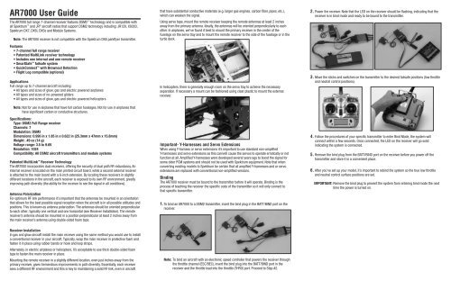
<strong>AR7000</strong> <strong>User</strong> <strong>Guide</strong>The <strong>AR7000</strong> full range 7-channel receiver features DSM2 technology and is compatible withall <strong>Spektrum</strong> and JR ® aircraft radios that support DSM2 technology including: JR12X, X9303,<strong>Spektrum</strong> DX7, DX6i, DX5e and Module Systems.Note: The <strong>AR7000</strong> receiver is not compatible with the <strong>Spektrum</strong> DX6 parkflyer transmitter.Features• 7-channel full range receiver• Patented MultiLink receiver technology• Includes one internal and one remote receiver• SmartSafe failsafe system• QuickConnect with Brownout Detection• Flight Log compatible (optional)ApplicationsFull range up to 7-channel aircraft including:• All types and sizes of glow, gas and electric powered airplanes• All types and sizes of no-powered gliders• All types and sizes of glow, gas and electric powered helicoptersNote: Not for use in airplanes that have full carbon fuselages. Not for use in airplanes thathave significant carbon or conductive structures.Specifications:Type: DSM2 Full Range receiverChannels: 7Modulation: DSM2Dimensions: 0.996 in x 1.85 in x 0.622 in (25.3mm x 47mm x 15.8mm)Weight: .49 oz (14 g)Voltage range: 3.5 to 9.6VResolution: 1024Compatibility: All DSM2 aircraft transmitters and module systemsPatented MultiLink Receiver TechnologyThe <strong>AR7000</strong> incorporates dual receivers, offering the security of dual path RF redundancy. Aninternal receiver is located on the main printed circuit board, while a second external receiveris attached to the main board with a 6-inch extension. By locating these receivers in slightlydifferent locations in the aircraft, each receiver is exposed to its own RF environment, greatlyimproving path diversity (the ability for the receiver to see the signal in all conditions).Antenna PolarizationFor optimum RF link performance it’s important that the antennas be mounted in an orientationthat allows for the best possible signal reception when the aircraft is in all possible attitudes andpositions. This is known as antenna polarization. The antennas should be oriented perpendicularto each other; typically one vertical and one horizontal (see Receiver Installation). The remotereceiver’s antenna should be mounted in a position perpendicular at least 2 inches away fromthe main receiver’s antenna using double-sided foam tape.that have substantial conductive materials (e.g. larger gas engines, carbon fiber, pipes, etc.),which can weaken the signal.Using servo tape, mount the remote receiver keeping the remote antennas at least 2 inchesaway from the primary antenna. Ideally, the antennas will be oriented perpendicularly to eachother. In airplanes, we’ve found it best to mount the primary receiver in the center of thefuselage on the servo tray and to mount the remote receiver to the side of the fuselage or in theturtle deck.In helicopters, there is generally enough room on the servo tray to achieve the necessaryseparation. If necessary a mount can be fashioned using clear plastic to mount the externalreceiver.Important- Y-Harnesses and Servo ExtensionsWhen using Y-harness or servo extensions it’s important to use standard non-amplifiedY-harnesses and servo extensions as this can/will cause the servos to operate erratically or notfunction at all. Amplified Y-harnesses were developed several years ago to boost the signal forsome older PCM systems and should not be used with <strong>Spektrum</strong> equipment. Note that whenconverting existing models to <strong>Spektrum</strong> be certain that all amplfied Y-harnesses and or servoextensions are replaced with conventional non-amplified versions.BindingThe <strong>AR7000</strong> receiver must be bound to the transmitter before it will operate. Binding is theprocess of teaching the receiver the specific code of the transmitter so it will only connect tothat specific transmitter.1. To bind an <strong>AR7000</strong> to a DSM2 transmitter, insert the bind plug in the BATT/BIND port on thereceiver.2. Power the receiver. Note that the LED on the receiver should be flashing, indicating that thereceiver is in bind mode and ready to be bound to the transmitter.3. Move the sticks and switches on the transmitter to the desired failsafe positions (low throttleand neutral control positions).4. Follow the procedures of your specific transmitter to enter Bind Mode, the system willconnect within a few seconds. Once connected, the LED on the receiver will go solidindicating the system is connected.5. Remove the bind plug from the BATT/BIND port on the receiver before you power off thetransmitter and store it in a convenient place.6. After you’ve set up your model, it’s important to rebind the system so the true low throttleand neutral control surface positions are set.IMPORTANT: Remove the bind plug to prevent the system from entering bind mode the nexttime the power is turned on.Receiver InstallationIn gas and glow aircraft install the main receiver using the same method you would use to installa conventional receiver in your aircraft. Typically, wrap the main receiver in protective foam andfasten it in place using rubber bands or hook and loop straps.Alternately, in electric airplanes or helicopters, it’s acceptable to use thick double-sided foamtape to fasten the main receiver in place.Mounting the remote receiver in a slightly different location, even just inches away from theprimary receiver, gives tremendous improvements in path diversity. Essentially, each receiversees a different RF environment and this is key to maintaining a solid RF link, even in aircraftNote: To bind an aircraft with an electronic speed controller that powers the receiver throughthe throttle channel (ESC/BEC), insert the bind plug into the BATT/BIND port in thereceiver and the throttle lead into the throttle (THRO) port. Proceed to Step #2.
SmartSafe FailsafeThe <strong>AR7000</strong> features SmartSafe failsafe. SmartSafe is ideal for mosttypes of aircraft. With SmartSafe, when signal is lost the throttle channelonly is driven to its preset failsafe position (normally low throttle) while all otherchannels hold last command.• Prevents unintentional electric motor response on start-up.• Eliminates the possibility of over-driving servos on start-up by storing preset failsafepositions.• Establishes low-throttle failsafe and maintains last-commanded control surface position ifthe RF signal is lost.Receiver Power Only• When the receiver only is turned on (no transmitter signal is present), the throttle channel hasno output, to avoid operating or arming the electronic speed control.• All other channels are driven to their preset failsafe positions set during binding.Note: Some analog servos may drift slightly during power-up even though no signal is present.This is normal.After Connection• When the transmitter is turned on and after the receiver connects to the transmitter, normalcontrol of all channels occurs.• After the system makes a connection, if loss of signal occurs SmartSafe drives the throttleservo only to its preset failsafe position (low throttle) that was set during binding.• All other channels hold their last commanded position. When the signal is regained, thesystem immediately (less than 4ms) regains control.Plugging in the LeadsPlug the servo leads into the appropriate servo ports in the receiver noting the polarity of theservo connector.Range TestingBefore each flying session and especially with a new model, it is important to perform a rangecheck. All <strong>Spektrum</strong> aircraft transmitters incorporate a range testing system which, whenactivated, reduces the output power, allowing a range check.30 paces (90 feet/28 meters)1. With the model restrained on the ground, stand 30 paces (approx. 90 feet/28 meters) awayfrom the model.2. Face the model with the transmitter in your normal flying position and place yourtransmitter into range check mode.3. You should have total control of the model with the button depressed at 30 paces (90feet/28 meters).4. If control issues exist, call the Product Support Team in the U.S. at 1-877-504-0233 forfurther assistance. In the UK or Germany use one of the following addresses.European Union: +44 (0) 1279 641 097 (United Kingdom)or email sales@horizonhobby.co.uk+49 4121 46199 66 (Deutschland)or email service@horizonhobby.deAdvanced Range TestingFor sophisticated models that have significant conductive material in them, the Advanced rangetest using a flight log is recommended. The advanced range check will confirm that the internaland remote receivers are operating optimally and that the installation (position of the receivers)is optimized for the specific aircraft. This Advanced Range Check allows the RF performance ofeach receiver to be evaluated and to optimize the locations of the remote receiver.Advanced Range Test1 Plug a Flight Log (SPM9540 - optional) into the Batt/Data port on the <strong>AR7000</strong> and turn onthe system (Tx and Rx).2. Advance the Flight Log until F-frame losses are displayed by pressing the button on theFlight Log.3. Have a helper hold your aircraft while observing the Flight Log data.4. Standing 30 paces away from the model, face the model with the transmitter in yournormal flying position and put your transmitter into range test mode. This causes reducedpower output from the transmitter.5. Have your helper position the model in various orientations (nose up, nose down, nosetoward the Tx, nose away from the Tx, etc.) while your helper watches the Flight Log notingany correlation between the aircraft’s orientation and frame losses. Do this for 1 minute.The timer on the transmitter can be used here.Receiver Power System RequirementsInadequate power systems that are unable to provide the necessary minimum voltage to thereceiver during flight have become the number one cause of in-flight failures. Some of thepower system components that affect the ability to properly deliver adequate power include• Receiver battery pack (number of cells, capacity, cell type, state of charge)• The ESC’s capability to deliver current to the receiver in electric aircraft• The switch harness, battery leads, servo leads, regulators etc.The <strong>AR7000</strong> has a minimum operational voltage of 3.5 volts; it is highly recommended thepower system be tested per the guidelines below.Recommended Power System Test <strong>Guide</strong>linesIf a questionable power system is being used (e.g. small or old battery, ESC that may not havea BEC that will support high current draw, etc.), it is recommended that a voltmeter be used toperform the following test.Note: The Hangar 9 Digital Servo & Rx Current Meter (HAN172) or the <strong>Spektrum</strong> Flight Log(SPM9540) are the perfect tools to perform the test below.Plug the voltmeter into an open channel port in the receiver and with the system on, load thecontrol surfaces (apply pressure with your hand) while monitoring the voltage at the receiver.The voltage should remain above 4.8 volts even when all servos are heavily loaded.Note: The latest generations of Nickel-Metal Hydride batteries incorporate a new chemistrymandated to be more environmentally friendly. These batteries when chargedwith peak detection fast chargers have tendencies to false peak (not fully charge)repeatedly. These include all brands of NiMH batteries. If using NiMH packs, beespecially cautious when charging, making absolutely sure that the battery is fullycharged. It is recommended to use a charger that can display total charge capacity.Note the number of mAh put into a discharged pack to verify it has been charged to fullcapacity.QuickConnect With Brownout DetectionYour <strong>AR7000</strong> features QuickConnect with Brownout Detection.• Should an interruption of power occur (brownout), the system will reconnect immediatelywhen power is restored (QuickConnect).• The LED on the receiver will flash slowly indicating a power interruption (brownout) hasoccurred.• Brownouts can be caused by an inadequate power supply (weak battery or regulator), aloose connector, a bad switch, an inadequate BEC when using an electronic speed controller,etc.• Brownouts occur when the receiver voltage drops below 3.5 volts thus interrupting controlas the servos and receiver require a minimum of 3.5 volts to operate.How QuickConnect With Brownout Detection Works• When the receiver voltage drops below 3.5 volts the system drops out (ceases to operate).• When power is restored the receiver immediately attempts to reconnect to the last twofrequencies that it was connected to.• If the two frequencies are present (the transmitter was left on) the system reconnectstypically in about 4/100 of a second.QuickConnect with Brownout Detection is designed to allow you to fly safely through most shortduration power interruptions, however, the root cause of these interruptions must be correctedbefore the next flight to prevent catastrophic safety issues.Note: If a brownout occurs in flight it is vital that the cause of the brownout be determinedand corrected.Flight Log (SPM9540 Optional)The Flight Log is compatible with the <strong>AR7000</strong>. The Flight Log displays overall RF linkperformance as well as the individual internal and external receiver link data. Additionally itdisplays receiver voltage.Using the Flight LogAfter a flight and before turning off the receiver or transmitter, plug the Flight Log into the Dataport on the <strong>AR7000</strong>. The screen will automatically display voltage e.g. 6v2= 6.2 volts.Note: When the voltage reaches 4.8 volts or less, the screen will flash indicating low voltage.Press the button to display the following information:A - Antenna fades on the internal antennaB – Not usedL – Antenna fades on the external antennaR – Not usedF - Frame lossH - HoldsAntenna fades—represents the loss of a bit of information on that specific antenna.Typically it’s normal to have as many as 50 to 100 antenna fades during a flight. If any singleantenna experiences over 500 fades in a single flight, the antenna should be repositioned in theaircraft to optimize the RF link.Frame loss—represents simultaneous antenna fades on all attached receivers. If the RF linkis performing optimally, frame losses per flight should be less than 20. A hold occurs when 45consecutive frame losses occur. This takes about one second. If a hold occurs during a flight, it’simportant to evaluate the system, moving the antennas to different locations and/or checking tobe sure the transmitter and receivers are all working correctly.Note: A servo extension can be used to allow the Flight Log to be plugged in moreconveniently. On some models, the Flight Log can be plugged in, attached and left onthe model using double-sided tape. Mounting the Flight Log conveniently to the sideframe is common with helicopters.ModelMatchSome <strong>Spektrum</strong> and JR transmitters offer a patent pending feature called ModelMatch.ModelMatch prevents the possibility of operating a model using the wrong model memory,potentially preventing a crash. With ModelMatch each model memory has its own unique code(GUID) and during the binding process the code is programmed into the receiver. Later, when thesystem is turned on, the receiver will only connect to the transmitter if the corresponding modelmemory is programmed on screen.Note: If at any time you turn on the system and it fails to connect, check to be sure thecorrect model memory is selected in the transmitter. Please note that the <strong>Spektrum</strong>Aircraft Modules do not have ModelMatch.
Tips on Using <strong>Spektrum</strong> 2.4GHzWhile your DSM equipped 2.4GHz system is intuitive to operate, functioning nearly identically to72MHz systems, following are a few common questions from customers.Q: Which do I turn on first, the transmitter or the receiver?A: If the receiver is turned off first—all servos except for the throttle will be driven to theirpreset failsafe positions set during binding. At this time the throttle channel doesn’t output apulse position preventing the arming of electronic speed controllers or in the case of an enginepowered aircraft the throttle servo remaining in its current position. When the transmitter isthen turned on the transmitter scans the 2.4GHz band and acquires two open channels. Thenthe receiver that was previously bound to the transmitter scans the band and finds the GUID(Globally Unique Identifier code) stored during binding. The system then connects and operatesnormally.If the transmitter is turned on first—the transmitter scans the 2.4GHz band and acquires twoopen channels. When the receiver is then turned on for a short period (the time it takes toconnect) all servos except for the throttle are driven to their preset failsafe positions while thethrottle has no output pulse. The receiver scans the 2.4GHz band looking for the previouslystored GUID and when it locates the specific GUID code and confirms uncorrupted repeatablepacket information, the system connects and normal operation takes place. Typically this takes2 to 6 seconds.Q: Sometimes the system takes longer to connect and sometimes it doesn’t connectat all?A: In order for the system to connect (after the receiver is bound) the receiver must receivea large number of consecutive uninterrupted perfect packets from the transmitter in order toconnect. This process is purposely critical of the environment ensuring that it’s safe to fly whenthe system does connect. If the transmitter is too close to the receiver (less that 4 ft.) or if thetransmitter is located near metal objects (metal TX case, the bed of a truck, the top of a metalwork bench, etc.) connection will take longer and in some cases connection will not occur asthe system is receiving reflected 2.4GHz energy from itself and is interpreting this as unfriendlynoise. Moving the system away from metal objects or moving the transmitter away from thereceiver and powering the system again will cause a connection to occur. This only happensduring the initial connection. Once connected the system is locked in and should a loss of signaloccur (failsafe) the system connects immediately (4ms) when signal is regained.Q: I’ve heard that the DSM system is less tolerant of low voltage. Is the correct?A: All DSM receivers have an operational voltage range of 3.5 to 9.6 volts. With most systemsthis is not a problem as in fact most servos cease to operate at around 3.8 volts. When usingmultiple high-current draw servos with a single or inadequate battery/power source, heavymomentary loads can cause the voltage to dip below this 3.5-volt threshold thus causing theentire system (servos and receiver) to brown out. When the voltage drops below the low voltagethreshold (3.5 volts), the DSM receiver must reboot (go through the startup process of scanningthe band and finding the transmitter) and this can take several seconds. Please read the receiverpower requirement section as this explains how to test for and prevent this occurrence.Q: Sometimes my receiver loses its bind and won’t connect requiring rebinding. Whathappens if the bind is lost in flight?A: The receiver will never lose its bind unless it’s instructed to. It’s important to understand thatduring the binding process the receiver not only learns the GUID (code) of the transmitter but thetransmitter learns and stores the type of receiver that it’s bound to. If the transmitter is placedinto bind mode, the transmitter looks for the binding protocol signal from a receiver. If no signalis present, the transmitter no longer has the correct information to connect to a specificreceiver and in essence the transmitter has been “unbound” from the receiver. We’ve hadseveral DX7 customers that use transmitter stands or trays that unknowingly depress thebind button and the system is then turned on losing the necessary information to allow theconnection to take place. We’ve also had DX7 customers that didn’t fully understand the rangetest process and pushed the bind button before turning on the transmitter also causing thesystem to “lose its bind.”Warranty PeriodExclusive Warranty- Horizon Hobby, Inc., (Horizon) warranties that the Products purchased (the “Product”)will be free from defects in materials and workmanship for a period of 1 year from the date of purchase bythe Purchaser.Limited Warranty(a) This warranty is limited to the original Purchaser (“Purchaser”) and is not transferable. REPAIROR REPLACEMENT AS PROVIDED UNDER THIS WARRANTY IS THE EXCLUSIVE REMEDY OF THEPURCHASER. This warranty covers only those Products purchased from an authorized Horizon dealer.Third party transactions are not covered by this warranty. Proof of purchase is required for warranty claims.Further, Horizon reserves the right to change or modify this warranty without notice and disclaims all otherwarranties, express or implied.(b) Limitations- HORIZON MAKES NO WARRANTY OR REPRESENTATION, EXPRESS OR IMPLIED,ABOUT NON-INFRINGEMENT, MERCHANTABILITY OR FITNESS FOR A PARTICULAR PURPOSE OF THEPRODUCT. THE PURCHASER ACKNOWLEDGES THAT THEY ALONE HAVE DETERMINED THAT THEPRODUCT WILL SUITABLY MEET THE REQUIREMENTS OF THE PURCHASER’S INTENDED USE.(c) Purchaser Remedy- Horizon’s sole obligation hereunder shall be that Horizon will, at its option, (i)repair or (ii) replace, any Product determined by Horizon to be defective. In the event of a defect, these arethe Purchaser’s exclusive remedies. Horizon reserves the right to inspect any and all equipment involvedin a warranty claim. Repair or replacement decisions are at the sole discretion of Horizon. This warrantydoes not cover cosmetic damage or damage due to acts of God, accident, misuse, abuse, negligence,commercial use, or modification of or to any part of the Product. This warranty does not cover damage dueto improper installation, operation, maintenance, or attempted repair by anyone other than Horizon. Returnof any goods by Purchaser must be approved in writing by Horizon before shipment.Damage LimitsHORIZON SHALL NOT BE LIABLE FOR SPECIAL, INDIRECT OR CONSEQUENTIAL DAMAGES, LOSS OFPROFITS OR PRODUCTION OR COMMERCIAL LOSS IN ANY WAY CONNECTED WITH THE PRODUCT,WHETHER SUCH CLAIM IS BASED IN CONTRACT, WARRANTY, NEGLIGENCE, OR STRICT LIABILITY.Further, in no event shall the liability of Horizon exceed the individual price of the Product on which liabilityis asserted. As Horizon has no control over use, setup, final assembly, modification or misuse, no liabilityshall be assumed nor accepted for any resulting damage or injury. By the act of use, setup or assembly, theuser accepts all resulting liability.If you as the Purchaser or user are not prepared to accept the liability associated with the use of thisProduct, you are advised to return this Product immediately in new and unused condition to the place ofpurchase.Law: These Terms are governed by Illinois law (without regard to conflict of law principals).Safety PrecautionsThis is a sophisticated hobby Product and not a toy. It must be operated with caution and common senseand requires some basic mechanical ability. Failure to operate this Product in a safe and responsiblemanner could result in injury or damage to the Product or other property. This Product is not intendedfor use by children without direct adult supervision. The Product manual contains instructions for safety,operation and maintenance. It is essential to read and follow all the instructions and warnings in themanual, prior to assembly, setup or use, in order to operate correctly and avoid damage or injury.Questions, Assistance, and RepairsYour local hobby store and/or place of purchase cannot provide warranty support or repair. Once assembly,setup or use of the Product has been started, you must contact Horizon directly. This will enable Horizon tobetter answer your questions and service you in the event that you may need any assistance. For questionsor assistance, please direct your email to productsupport@horizonhobby.com, or call 877.504.0233 tollfree to speak to the Product Support department.Inspection or RepairsIf this Product needs to be inspected or repaired, please call for a Return Merchandise Authorization (RMA).Pack the Product securely using a shipping carton. Please note that original boxes may be included, butare not designed to withstand the rigors of shipping without additional protection. Ship via a carrier thatprovides tracking and insurance for lost or damaged parcels, as Horizon is not responsible for merchandiseuntil it arrives and is accepted at our facility. A Service Repair Request is available at www.horizonhobby.com on the “Support” tab. If you do not have internet access, please include a letter with your completename, street address, email address and phone number where you can be reached during business days,
your RMA number, a list of the included items, method of payment for any non-warranty expenses and abrief summary of the problem. Your original sales receipt must also be included for warranty consideration.Be sure your name, address, and RMA number are clearly written on the outside of the shipping carton.Warranty Inspection and RepairsTo receive warranty service, you must include your original sales receipt verifying the proof-of-purchasedate. Provided warranty conditions have been met, your Product will be repaired or replaced free of charge.Repair or replacement decisions are at the sole discretion of Horizon Hobby.Non-Warranty RepairsShould your repair not be covered by warranty the repair will be completed and payment will be requiredwithout notification or estimate of the expense unless the expense exceeds 50% of the retail purchase cost.By submitting the item for repair you are agreeing to payment of the repair without notification. Repairestimates are available upon request. You must include this request with your repair. Non-warranty repairestimates will be billed a minimum of ½ hour of labor. In addition you will be billed for return freight.Please advise us of your preferred method of payment. Horizon accepts money orders and cashiers checks,as well as Visa, MasterCard, American Express, and Discover cards. If you choose to pay by credit card,please include your credit card number and expiration date. Any repair left unpaid or unclaimed after 90days will be considered abandoned and will be disposed of accordingly. Please note: non-warranty repair isonly available on electronics and model engines.Electronics and engines requiring inspection or repair should be shipped to the following address:Horizon Service Center4105 Fieldstone RoadChampaign, Illinois 61822All other Products requiring warranty inspection or repair should be shipped to the following address:Horizon Product Support4105 Fieldstone RoadChampaign, Illinois 61822Please call 877-504-0233 or e-mail us at productsupport@horizonhobby.com with any questions orconcerns regarding this product or warranty.European Union:Electronics and engines requiring inspection or repair should be shipped to one of the following addresses:Horizon Hobby UKUnits 1-4 Ployters RdStaple Tye, HarlowEssex CM18 7NSUnited KingdomPlease call +44 (0) 1279 641 097 or email sales@horizonhobby.co.uk with any questions or concernsregarding this product or warranty.Horizon Technischer ServiceHamburger Str. 1025335 ElmshornGermanyPlease call +49 4121 46199 66 or email service@horizonhobby.de with any questions or concernsregarding this product or warranty.FCC InformationThis device complies with part 15 of the FCC rules. Operation is subject to the following twoconditions: (1) This device may not cause harmful interference, and (2) this device must accept anyinterference received, including interference that may cause undesired operation.Caution: Changes or modifications not expressly approved by the party responsible forcompliance could void the user’s authority to operate the equipment.This product contains a radio transmitter with wireless technology which has been tested and foundto be compliant with the applicable regulations governing a radio transmitter in the 2.400GHz to2.4835GHz frequency range.Instructions for Disposal of WEEE by <strong>User</strong>s in theEuropean UnionThis product must not be disposed of with other waste. Instead, it is the user’s responsibilityto dispose of their waste equipment by handing it over to a designated collection point for therecycling of waste electrical and electronic equipment. The separate collection and recycling of yourwaste equipment at the time of disposal will help to conserve natural resources and ensure that it isrecycled in a manner that protects human health and the environment. For more information aboutwhere you can drop off your waste equipment for recycling, please contact your local city office,your household waste disposal service or where you purchased the product.Declaration of Conformity(in accordance with ISO/IEC 17050-1)No. HH20081022Product(s):Item Number(s):Equipment class: 1<strong>Spektrum</strong> <strong>AR7000</strong> ReceiverSPM6070The objects of declaration described above are in conformity with the requirements of thespecifications listed below, following the provisions of the European R&TTE directive 1999/5/EC:EN 300-328 v1.7.1EN 301 489-1 v.1.6.1EN 301 489-17 v.1.2.1Signed for and on behalf of:Horizon Hobby, Inc.Champaign, IL USAOct 22, 2008ERM requirements for wideband transmission systemsoperating in the 2.4 GHz ISM bandGeneral EMC requirements for Radio equipmentSteven A. HallVice PresidentInternational Operations and Risk ManagementHorizon Hobby, Inc.US patent number 7,391,320. Other patents pending.DSM and DSM2 are trademarks or registered trademarks of Horizon Hobby, Inc. The <strong>Spektrum</strong> trademark is usedwith permission of Bachmann Industries, Inc. <strong>Spektrum</strong> radios and accessories are exclusively available from HorizonHobby, Inc.Revised 10/08 10654.4