DSX12 Instruction & Programming Manual - MacGregor Industries
DSX12 Instruction & Programming Manual - MacGregor Industries
DSX12 Instruction & Programming Manual - MacGregor Industries

You also want an ePaper? Increase the reach of your titles
YUMPU automatically turns print PDFs into web optimized ePapers that Google loves.
12-CHANNEL COMPUTER RADIOSYSTEM WITH SPEKTRUM 2.4GHz DSMTECHNOLOGYI-1INSTRUCTION ANDPROGRAMMING MANUAL
Table of ContentsUsing the <strong>Manual</strong>..........................................................................................................................................I-11Section 1: Transmitter and Receiver Features and Specifications.................................................................I-12JR 12X Transmitter....................................................................................................................................I-12Features.....................................................................................................................................................I-12Specifications.............................................................................................................................................I-12Flash Memory................................................................................................................................................I-12Battery Alarm and Display.............................................................................................................................I-12JR R1221 Receiver....................................................................................................................................I-13Features.....................................................................................................................................................I-13Specifications.............................................................................................................................................I-13Charging........................................................................................................................................................I-14Transmitter/Receiver..................................................................................................................................I-14JR Transmitter Charging............................................................................................................................I-14Using the Included Charger.......................................................................................................................I-14Control Stick Tension Adjustment.................................................................................................................I-15Advanced Digital Trims..................................................................................................................................I-15Control Stick Length......................................................................................................................................I-15Neck Strap Attachment..................................................................................................................................I-15Installing the Receiver...................................................................................................................................I-16Installing the JR R1221.............................................................................................................................I-16Binding..........................................................................................................................................................I-17How to Bind...............................................................................................................................................I-17ModelMatch...................................................................................................................................................I-18Failsafe Functions..........................................................................................................................................I-18SmartSafe......................................................................................................................................................I-19Receiver Power Only..................................................................................................................................I-19After Connection........................................................................................................................................I-19Failsafe for JR/Spektrum...........................................................................................................................I-19Receiver Power Only..................................................................................................................................I-19After Connection........................................................................................................................................I-20<strong>Programming</strong> SmartSafe...........................................................................................................................I-20<strong>Programming</strong> Preset Failsafe for JR/Spektrum.........................................................................................I-20Range Testing................................................................................................................................................I-21Range Testing............................................................................................................................................I-21Advanced Range Testing Using a Flight Log..............................................................................................I-21Advanced Range Testing............................................................................................................................I-22Flight Log - Optional for JR R1221 Receiver.................................................................................................I-23Using the Flight Log...................................................................................................................................I-23Receiver Power System Requirements.........................................................................................................I-24Recommended Power System Guidelines.....................................................................................................I-24Tips On Using 2.4GHz Systems.....................................................................................................................I-25Airplane - ACRO Mode...................................................................................................................................A-1Transmitter Identification ACRO.....................................................................................................................A-2System Mode.................................................................................................................................................A-4To Enter System Mode................................................................................................................................A-4Function Mode................................................................................................................................................A-5To Enter Function Mode..............................................................................................................................A-5Function Mode List.........................................................................................................................................A-5System Mode.................................................................................................................................................A-6Accessing the System Mode.......................................................................................................................A-6I-2
11: Servo Reversing.....................................................................................................................................A-31To Program Servo Reverse.......................................................................................................................A-3112: Travel Adjust...........................................................................................................................................A-31To Program Travel Adjust Values..............................................................................................................A-3113: Dual Rate and Exponential.....................................................................................................................A-32To Program Dual Rate and Exponential Values.........................................................................................A-32Assigning Dual and Expo Rates to Flight Modes......................................................................................A-32To Assign D/R and Expo Values to Flight Modes......................................................................................A-3215: Sub Trim.................................................................................................................................................A-33To Program Sub Trim Values....................................................................................................................A-3316: Throttle Hold..........................................................................................................................................A-33To Activate Throttle Hold...........................................................................................................................A-3318: Throttle Curves.......................................................................................................................................A-34To Program a Throttle Curve....................................................................................................................A-3424: Servo Speed...........................................................................................................................................A-35To Adjust Servo Speed..............................................................................................................................A-3531: Snap Roll................................................................................................................................................A-36If the Snap Roll Function Is To Be Used...................................................................................................A-3632: Differential..............................................................................................................................................A-37To Use the Aileron Differential Function....................................................................................................A-3733: Balance...................................................................................................................................................A-38To Program the Balance Function.............................................................................................................A-3844: Gyro Sensor...........................................................................................................................................A-39Gyro Connections.....................................................................................................................................A-39Gyro Gain..................................................................................................................................................A-39To Access the Gyro Sensor.......................................................................................................................A-3945: Governer.................................................................................................................................................A-40To Activate the Governor Screen...............................................................................................................A-40To Access the Governor Screen................................................................................................................A-4062: Aileron to Rudder...................................................................................................................................A-41To Program Aileron-to-Rudder Mixing......................................................................................................A-4163: Elevator to Flap.......................................................................................................................................A-42To Program Elevator-to-Flap Mixing.........................................................................................................A-4264: Rudder to Aileron/Elevator Mix..............................................................................................................A-43To Program the Rudder-to-Aileron Mix.....................................................................................................A-4366: Flap System............................................................................................................................................A-44To Program the Flap System.....................................................................................................................A-44Flap...........................................................................................................................................................A-45ELEV - Elevator Compensation.................................................................................................................A-45Flight Modes.............................................................................................................................................A-45Delay.........................................................................................................................................................A-4551 thru 58: Programmable Mixers...............................................................................................................A-46Standard Programmable Mixer - (Std. Prog Mixer)..................................................................................A-46Master Channel - (Std. Prog Mixer)..........................................................................................................A-47Slave Channel - (Std. Prog Mixer)............................................................................................................A-48Switch Position.........................................................................................................................................A-48Offset........................................................................................................................................................A-49Mix Values................................................................................................................................................A-49CLR Button - (Std. Prog Mixer)................................................................................................................A-50To Inhibit a Mix.........................................................................................................................................A-50Multi-Point Programmable Mixer..............................................................................................................A-50Master Channel.........................................................................................................................................A-50I-4
81: Model Name.............................................................................................................................................H-8To Name a Model........................................................................................................................................H-828: Model Reset.............................................................................................................................................H-8To Reset a Model Memory..........................................................................................................................H-889: Type Select...............................................................................................................................................H-9To Select a Model Type...............................................................................................................................H-985: Modulation - (12X MV System only)......................................................................................................H-10To Program a Modulation Type.................................................................................................................H-1093: Frequency Select - (12X MV system only).............................................................................................H-11To Select a Frequency...............................................................................................................................H-1183: Trim System...........................................................................................................................................H-12LST Trim...................................................................................................................................................H-12To Adjust the Trim Rates...........................................................................................................................H-13To Select the LST Trim Function...............................................................................................................H-1391: Stick Position Switch.............................................................................................................................H-14To Program a Stick Position Switch.........................................................................................................H-1492: Flight Mode Name..................................................................................................................................H-15To Program a Flight Mode Name..............................................................................................................H-1586: Transfer..................................................................................................................................................H-16Preparing the 12X to Receive a Model Transfer........................................................................................H-16Preparing the 12X to Send a Model Transfer............................................................................................H-1797: Warning..................................................................................................................................................H-18To Program a Warning..............................................................................................................................H-1898: Settings..................................................................................................................................................H-19To Change Transmitter Settings................................................................................................................H-1917: Device Select..........................................................................................................................................H-20Assigning the Flight Mode Switch............................................................................................................H-20To Assign the Flight Mode to a Switch.....................................................................................................H-20Activating Extra Flight Modes 3 and 4......................................................................................................H-21To Activate 2 Additional Flight Modes (Flight Modes 3 and 4).................................................................H-21Assigning the Throttle Hold Switch..........................................................................................................H-21To Assign the Throttle Hold to a Switch...................................................................................................H-22Stunt Trim.....................................................................................................................................................H-22Hover Analog............................................................................................................................................H-23Switch Assignments.................................................................................................................................H-23To Change One or More Switch Assignments...........................................................................................H-24Assigning/Activating Governor, Gyro and Pitch 2 Functions.....................................................................H-24If the Governor, Gyro or Pitch 2 Functions Are To Be Used......................................................................H-24Deactivating Channels...............................................................................................................................H-2534: Swashplate Type.....................................................................................................................................H-26To Select a Swashplate Type.....................................................................................................................H-26Function Mode..........................................................................................................................................H-27To Enter the Function Mode List...............................................................................................................H-2711: Servo Reversing.....................................................................................................................................H-27To Program Servo Reverse.......................................................................................................................H-2712: Travel Adjust...........................................................................................................................................H-28To Program Travel Adjust Values..............................................................................................................H-2813: Dual Rate and Exponential.....................................................................................................................H-29To Program Dual Rate and Exponential Functions....................................................................................H-29AUTO Function..........................................................................................................................................H-3015: Sub Trim.................................................................................................................................................H-30To Program Sub Trim Values....................................................................................................................H-30I-6
16: Throttle Hold..........................................................................................................................................H-31Accessing the Throttle Hold Function.......................................................................................................H-31Stick Auto.................................................................................................................................................H-31To Activate the Stick Auto Function..........................................................................................................H-31Hold Delay................................................................................................................................................H-31To Activate the Hold Delay........................................................................................................................H-3118: Throttle Curves.......................................................................................................................................H-32Accessing the Throttle Curve Function.....................................................................................................H-32Exponential...............................................................................................................................................H-33Trim (Mechanical Trim Lever)...................................................................................................................H-33Hovering Throttle......................................................................................................................................H-3324: Servo Speed...........................................................................................................................................H-34To Adjust Servo Speed..............................................................................................................................H-3442: Mix to Throttle........................................................................................................................................H-35<strong>Programming</strong> the Cyclic-to-Throttle Function...........................................................................................H-35Selecting the Desired Flight Modes for Cyclic-to-Throttle Mixing.............................................................H-3544: Gyro Sensor...........................................................................................................................................H-36Accessing the Gyro Gain Function............................................................................................................H-3645: Governor................................................................................................................................................H-37Accessing the Governor Function.............................................................................................................H-3747: Tail Curves - (Use Only with Non-Heading Hold Gyros).........................................................................H-38Accessing the Tail Curve Function............................................................................................................H-38Exponential...............................................................................................................................................H-3861: Dual Pitch...............................................................................................................................................H-3965: Swashplate Mix......................................................................................................................................H-40Aileron, Elevator and Pitch Authority........................................................................................................H-40Aileron to Elevator/ Elevator to Aileron Mix..............................................................................................H-403D Electronic Cyclic Ring..........................................................................................................................H-40Exponential Function.................................................................................................................................H-40Elevator-to-Pitch Canceller........................................................................................................................H-41Accessing the Swashplate Mixing Function..............................................................................................H-4168: Pitch Curves...........................................................................................................................................H-42Accessing the Pitch Curve Function.........................................................................................................H-42Exponential...............................................................................................................................................H-43Hovering Pitch..........................................................................................................................................H-4351 thru 58: Programmable Mixers...............................................................................................................H-44Standard Programmable Mixer - (Std. Prog Mixer)..................................................................................H-44Master Channel - (Std. Prog Mixer)..........................................................................................................H-45Slave Channel - (Std. Prog Mixer)............................................................................................................H-46Switch Position.........................................................................................................................................H-46Offset........................................................................................................................................................H-47Mix Values................................................................................................................................................H-47CLR Button - (Std. Prog Mixer)................................................................................................................H-48To Inhibit a Mix.........................................................................................................................................H-48Multi-Point Programmable Mixer..............................................................................................................H-48Master Channel.........................................................................................................................................H-49Slave Channel...........................................................................................................................................H-49Point Names/Numbers..............................................................................................................................H-49Current Point Setting................................................................................................................................H-49Vertical Line..............................................................................................................................................H-50Multi-Point Programmable Mixer..............................................................................................................H-50Graph........................................................................................................................................................H-50I-7
Points that Can Be Added and Adjusted...................................................................................................H-50Exponential...............................................................................................................................................H-50Slave Channel Position.............................................................................................................................H-50Master Channel Position...........................................................................................................................H-51Switch Select............................................................................................................................................H-51CLR Button...............................................................................................................................................H-51LIST Button...............................................................................................................................................H-51ENT Button................................................................................................................................................H-51To Inhibit a Mixer (Turn it off entirely)......................................................................................................H-5175: Monitor...................................................................................................................................................H-5276: Mix Monitor............................................................................................................................................H-5278: Trainer....................................................................................................................................................H-5312X Used as Master (Instructor)..............................................................................................................H-5312X Used as Slave (Student)....................................................................................................................H-5387: Timer......................................................................................................................................................H-5412X Sailplane Mode........................................................................................................................................S-1Introduction................................................................................................................................................S-1Transmitter Identification - Sailplane..........................................................................................................S-2<strong>Programming</strong> a Sailplane...............................................................................................................................S-4System Mode.................................................................................................................................................S-4To Enter System Mode................................................................................................................................S-4Function Mode................................................................................................................................................S-5To Enter Function Mode..............................................................................................................................S-5System Mode.................................................................................................................................................S-5Accessing the System Menu.......................................................................................................................S-584: Model Select - (Copy Function)................................................................................................................S-6To Select a Model Memory.........................................................................................................................S-6Model Copy.................................................................................................................................................S-7To Copy a Model to Another Internal Memory............................................................................................S-781: Model Name.............................................................................................................................................S-8To Name a Model........................................................................................................................................S-828: Model Reset.............................................................................................................................................S-9To Reset a Model Memory..........................................................................................................................S-989: Type Select...............................................................................................................................................S-9To Select a Model Type...............................................................................................................................S-985: Modulation - (12X MV System only)......................................................................................................S-10To Program a Modulation Type.................................................................................................................S-1093: Frequency Select - (12X MV system only).............................................................................................S-11To Select a Frequency...............................................................................................................................S-1183: Trim System...........................................................................................................................................S-12LST Trim...................................................................................................................................................S-12To Adjust the Trim Rates...........................................................................................................................S-13To Select the LST Trim Function...............................................................................................................S-1391: Stick Position Switch.............................................................................................................................S-14To Program a Stick Position Switch.........................................................................................................S-1492: Flight Mode Name..................................................................................................................................S-15To Program a Flight Mode Name..............................................................................................................S-1586: Transfer..................................................................................................................................................S-16Preparing the 12X to Receive a Model Transfer........................................................................................S-16Preparing the 12X to Send a Model Transfer............................................................................................S-17I-8
97: Warning..................................................................................................................................................S-18To Program a Warning..............................................................................................................................S-1898: Settings..................................................................................................................................................S-19To Change Transmitter Settings................................................................................................................S-1917: Device Select..........................................................................................................................................S-19Flight Modes.............................................................................................................................................S-20Activating and Assigning Primary Flight Modes.......................................................................................S-21Activating and Assigning Additional Flight Modes....................................................................................S-21Aileron and Rudder Common Trims.........................................................................................................S-21Motor Function.........................................................................................................................................S-22Flap and AUX Functions............................................................................................................................S-22Activating/Inhibiting Channels..................................................................................................................S-2222: Wing Type..............................................................................................................................................S-23Function Mode..........................................................................................................................................S-23To Enter the Function Mode List...............................................................................................................S-2311: Servo Reversing.....................................................................................................................................S-24To Program Servo Reverse.......................................................................................................................S-2412: Travel Adjust...........................................................................................................................................S-24To program Travel Adjust Values..............................................................................................................S-2413: Dual Rate and Exponential.....................................................................................................................S-25To Program Dual Rate and Exponential Functions....................................................................................S-25AUTO function..........................................................................................................................................S-2515: Sub Trim.................................................................................................................................................S-26To Program Sub Trim Values....................................................................................................................S-26Motor Hold................................................................................................................................................S-26To Access Motor Hold in the Function List...............................................................................................S-2621: Flaperon Mix...........................................................................................................................................S-27To Access Flaperon Mix............................................................................................................................S-2724: Servo Speed...........................................................................................................................................S-28To Adjust Servo Speed..............................................................................................................................S-2825: Camber System......................................................................................................................................S-29To Access the Camber System.................................................................................................................S-2932: Differential..............................................................................................................................................S-30To Use the Aileron Differential Function....................................................................................................S-3033: Balance...................................................................................................................................................S-31To Program the Balance Function.............................................................................................................S-3144: Gyro Sensor...........................................................................................................................................S-32To Access the Gyro Sensor.......................................................................................................................S-3246: Rudder-to-Spoiler Mix............................................................................................................................S-32To Access Rudder-to-Spoiler Mix.............................................................................................................S-3262: Aileron-to-Rudder Mix............................................................................................................................S-33To Access Aileron-to-Rudder Mix.............................................................................................................S-3363: Elevator-to-Flap Mix...............................................................................................................................S-34To Access Elevator-to-Flap Mix.................................................................................................................S-3469: Flap Rate................................................................................................................................................S-35To Access the Flap Rate Function.............................................................................................................S-3571: Brake System.........................................................................................................................................S-36To Access the Brake System.....................................................................................................................S-3651 thru 58: Programmable Mixers...............................................................................................................S-37Additionally There are Two Options for Master Channels.........................................................................S-37Standard Programmable Mixer - (Std. Prog Mixer)..................................................................................S-37I-9
Master Channel - (Std. Prog Mixer)..........................................................................................................S-38Slave Channel - (Std. Prog Mixer)............................................................................................................S-39Switch Position.........................................................................................................................................S-39Offset........................................................................................................................................................S-39Mix Values................................................................................................................................................S-40LR Button - (Std. Prog Mixer)..................................................................................................................S-40To Inhibit a Mix.........................................................................................................................................S-40Multi-Point Programmable Mixer..............................................................................................................S-41Master Channel.........................................................................................................................................S-41Slave Channel...........................................................................................................................................S-41Point Names/Numbers..............................................................................................................................S-41Current Point Setting................................................................................................................................S-42Vertical Line..............................................................................................................................................S-42Multi-Point Programmable Mixer..............................................................................................................S-42Graph........................................................................................................................................................S-42Points That Can Be Added and Adjusted..................................................................................................S-42Exponential...............................................................................................................................................S-42Slave Channel Position.............................................................................................................................S-43Master Channel Position...........................................................................................................................S-43Switch Select............................................................................................................................................S-43CLR Button...............................................................................................................................................S-43LIST Button...............................................................................................................................................S-43ENT Button................................................................................................................................................S-43To Inhibit a Mixer (Turn it off completely)................................................................................................S-4375: Monitor...................................................................................................................................................S-4476: Mix Monitor............................................................................................................................................S-4478: Trainer....................................................................................................................................................S-4512X Used as Master (Instructor)..............................................................................................................S-4512X Used as Slave (Student)....................................................................................................................S-4587: Timer......................................................................................................................................................S-46General Information.......................................................................................................................................W-1FCC Information.........................................................................................................................................W-1Daily Flight Checks.....................................................................................................................................W-1Servo Precautions......................................................................................................................................W-1General Notes............................................................................................................................................W-1Safety Do’s and Don’ts for Pilots...............................................................................................................W-2Federal Aviation Administration.....................................................................................................................W-2Purpose.....................................................................................................................................................W-2Background................................................................................................................................................W-2Operating Standards..................................................................................................................................W-2Information Provided By............................................................................................................................W-2Warranty Information....................................................................................................................................W-3Three Year Warranty Period.......................................................................................................................W-3Limited Warranty.......................................................................................................................................W-3Damage Limits...........................................................................................................................................W-3Safety Precautions.....................................................................................................................................W-3Questions, Assistance, and Repairs...........................................................................................................W-3Inspection or Repairs.................................................................................................................................W-4Warranty Inspection and Repairs...............................................................................................................W-4Non-Warranty Repairs...............................................................................................................................W-4I-10
Using the <strong>Manual</strong>The 12X offers sophisticated programming features for three model types: airplanes, helicopters and sailplanes. This manual isdivided into four sections. The first section, pages I-14 through I-26, includes common transmitter features and specifications plusoverall operational information (e.g., charging batteries, binding, range checking and Frequently Asked Questions) sections that arecommon to all model types. The remaining three sections, pages A-1 through S-41, include instructions for using model-specificprogramming for airplane, helicopter and sailplane functions. An explanation of each programming function is provided, followed byillustrations of its corresponding display and instructions on how to access and adjust the function.I-11
Section 1: Transmitter and Receiver Features and SpecificationsJR 12X TransmitterJR’s 12X offers airplane, helicopter and sailplane pilotsthe highest level of sophisticated programming featurescombined with the benefits of Spektrum’s 2.4GHz DSM ®radio link technology. DSM (Digital Spektrum Modulation)technology offers a far superior RF link over narrow bandsystems, providing a higher level of confidence and safety.Now with even the most sophisticated models you’ll no longerhave to wait for an open frequency, worry about someoneunintentionally powering up on the same frequency or haveto plan a frequency-based flight matrix for competition. Andfor response-critical aircraft like 3D helicopters and airplanes,latency (the time it takes for a stick input to translate to a servooutput) is significantly reduced, providing a more responsive,precise connection to your model.Features• Backlit screen• Ergonomic magnesium case• Digital 3 + 1 trims (3 digital + 1 analog [throttle] trim)• Newly designed ball bearing gimbals• The choice of a fully integrated 2.4GHz Spektrum systemor module-based system that allows the easy band switchfrom 2.4GHz Spektrum technology to 72MHz• The highest level of sophisticated programming for threemodel types: Airplane, Helicopter, Sailplane• Rolling Selector input• Flight Mode naming• 50-model memory• Patented DuaLink ® Technology (2.4GHz system only)• ModelMatch (2.4GHz system only)• ServoSyncSpecifications• Model Number: (JRP1200 12X 2.4/JRP1210 12X MV)• Number of Channels:12• Modulation Type: Direct Sequence Spread Spectrum DSM2/DSM1 protocolNote: 12X MV also operates in PPM, Z-PCM and S-PCMwith the included 72MHz module. (A-PCM not supportedin the US by Horizon Hobby - Japan market only)• Band: 2.400–2.483GHz• Spectral Capacity: 40 simultaneous systems• Transmitter Current: 180mA/DSM2;280mA/DSM1; 200mA/PCM/• Resolution: 2048Flash MemoryAll preprogrammed data is protected by a flash memory thatprotects stored programming should the main transmitterbattery ever fail or need replacing.Battery Alarm and DisplayWhen the transmitter voltage drops below 9.0 volts, the displayflashes “BATT LOW” and an alarm sounds.If you are flying when this occurs, land immediately.I-12
JR R1221 ReceiverThe R1221 receiver combines one internal with three remotereceivers, offering superior path diversity. The radio systemsimultaneously transmits on two frequencies, creating up tofour RF paths on two different 2.4GHz channels. This multi pathredundancy, plus the fact that each of the 4 receivers are locatedin different locations throughout the aircraft, exposes each toa different RF environment creating a superior RF link in allconditions. The JR R1221 allows an optional Flight Log datarecorder (JRPA145) to be used. The Flight Log can be pluggedinto the data port of the receiver to provide RF link data of theprevious flight, allowing the confirmation of the operationalperformance of the system receiver antenna.Features• 12 channels• 1 internal receiver• 3 remote receivers• Patented MultiLink technology• Two Types of Failsafe: SmartSafe and preprogrammedfailsafe• Instant QuickConnect (w/brownout detection) should apower interruption occur• Flight Log compatibleSpecifications• Number of Channels: 12• Modulation: DSM2• Band: 2.400–2.4835GHz• Dimensions (WxLxH): 1.48 x 2.1 x .628 in• Weight: Main .7 oz (20 g) Remote 3 g/.2 oz each• Current: 70mA• Voltage Range: 3.5 to 10V• Resolution: 2048Compatible ReceiversNote: The 12X includes a JR1221 12-channel receiver.The 12X is also compatible will all current JR andSpektrum DSM aircraft receivers including:• AR6000• AR6100• AR6100e• AR6200• AR63006-channel Parkflyer receiver6-channel 3.5-gram Parkflyer receiver6-channel 3.5-gram end pinParkflyer receiver6-channel full range receiver6-channel 2-gram Nanolite slow and microflyer receiver• AR7000• AR9000• AR9100• R921• R922• R12227-channel full range receiver9-channel full range receiver9-channel PowerSafe full range receiver9-channel full range receiver9-channel PowerSafe full range receiver12-channel PowerSafe full range receiverImportant: When using the 12X with park flyer receivers(the AR6000, AR6100, AR6100e, and AR6300), it’simperative that these receivers only be flown in parkflyertypeaircraft (small electric airplanes or mini and microhelicopters). Flying receivers designed for parkflyers inlarger aircraft could cause a loss of control.I-13
ChargingTransmitter/ReceiverNote: It is imperative that you fully charge both thetransmitter and the receiver battery packs prior to eachflying session and that you check the condition of thereceiver battery between each flight using a reliable batterytester with a built-in load. The included wall chargercharges at a 250mA rate. In order to fully charge theincluded batteries, it’s necessary to leave the charger andbatteries hooked up to the included wall charger for 8–10hours.An optional fast charger can be used to charge both thetransmitter and receiver batteries, however, it’s imperative thatthe batteries are properly charged and the charge conditionbe checked prior to flight. “False Peaking” is a commonoccurrence with many fast chargers/batteries, giving anindication that the battery is fully charged when in fact thebattery is only partially charged. False Peaking can lead todisastrous results and it is the pilot’s responsibility to verify thecharge condition of the batteries before every flight. (Also seeReceiver Power Requirements page I-26.)JR Transmitter ChargingThe center pin on all JR ® transmitters is negative. Therefore,the center pin on all JR chargers is negative, not positive. Thisis different from many other manufacturers’ chargers and radiosystems. Beware of improper connections based on “colorcoded”wire leads, as they may not apply in this instance. Youmust make sure that the center pin of your JR transmitter isalways connected to the negative pole for correct polarity.Note: When using a fast charger to charge the transmitterbattery, do not exceed 1.5 amps (or 1500mA) charge rateor damage to the transmitter or battery can occur.Using the Included ChargerThe pilot lamps should always be on during the chargingoperation. If not, check to make sure that both the transmitterand receiver are switched off.Do not use the charger for equipment other than JR. Thecharging plug polarity may not be the same. Equipment damagecan result.Do not use other manufacturers’ after-market accessories thatplug into the transmitter’s charging jack if you are unsure ofthe polarity compatibility with your radio. Seek expert advice toavoid possible damage.During the charging operation, the charger’s temperature isslightly elevated.Charger Pigtail for TransmitterBLACK TO POSITIVEBLACK W/WHITE STRIPE TO NEGATIVETransmitter Charge Jack Polarity- +I-14
Control Stick Tension AdjustmentStick tension adjustments are accessible through covers thatare located on the back of the transmitter (see photo). Carefullypull back the cover or remove the grip to access the gimbals’tension screws and then, using a small Phillips screwdriver,adjust each gimbal’s tension screw for the desired tension(counterclockwise to loosen stick tension; clockwise to tightenstick tension).Advanced Digital TrimsThe 12X features Advanced digital trims. On the Normal displayscreen, if a trim lever is moved, the screen will automaticallychange to display the graphic position for the trim beingadjusted. The 12X Aileron, Elevator and Rudder trim levers andthe right and left side levers feature an audible center trim beep.This is helpful in determining the trim lever’s center positionduring flight. In addition, the frequency of each trim stepchanges from full right/up to full left/down, allowing the pilot tobe aware of the general trim position audibly without looking atthe transmitter.By using the Trim System Function Code 83 located in theSystem Mode, the amount of travel per each trim step can beadjusted as needed to match your specific application.Please note that when the 12X transmitter is turned off, the trimvalues are stored in memory and are recalled when the systemis turned back on.Control Stick LengthUse a 2mm Allen wrench to unlock the setscrew to adjustthe stick length. Turn the wrench counterclockwise to loosenthe screw. Then, turn the stick clockwise to shorten orcounterclockwise to lengthen the overall stick length. After thecontrol stick length has been adjusted to suit your flying style,tighten the 2mm setscrew. If you desire longer sticks, JR offersa stick (JRPA047) that is approximately one inch longer thanstandard, and has various length anodized aluminum stick endsavailable (JRPA040-JRPA045). These stick ends are craftedfrom bar stock aluminum, and are available at your local JRdealer.SETSCREWTIGHTENLOOSENNeck Strap AttachmentAn eyelet is provided on the face of the 12X transmitter thatallows you to connect a Neck Strap.I-15
Installing the ReceiverInstalling the JR R1221The JR R1221 incorporates a single internal receiver and threeremote receivers offering the security of four simultaneous RFlinks for the ultimate in multi-path RF security. One internalreceiver is located on the main PC board, while 2 remotereceivers must be plugged into one of the antenna portsin order for the system to operate. A third remote receiver(included) can be plugged into the remaining remote antennaport giving a total of four operational receivers. By locatingthese receivers in different locations throughout the aircraft,each receiver is exposed to its own RF environment, greatlyimproving path diversity (the ability of the receiver to see thesignal in all conditions).Using double-sided foam tape (servo tape), mount the remotereceiver(s) keeping the remote antenna(s) at least 2” awayfrom the primary antenna. Ideally the antennas will be orientedperpendicular to each other; however, we’ve found this to notbe critical. 6”, 9”, 12”, 24”, and 36” leads are available and insophisticated aircraft, we’ve found it best to mount the remotereceivers in different parts of the aircraft keeping the remoteantennas as far away as practical from any conductive materials.A typical installation would include the main receiver mountedin the conventional location in the fuselage and the remoteantennas in the nose (jets) in the top turtle deck and even in thetail. The optimum location is as far away from any conductivematerials as practical.In helicopters, there is generally enough room on the servo trayto achieve the necessary separation. If necessary a mount canbe made using clear plastic to mount the external antenna.Other important installation tips:1. The servos should be mounted using rubber grommets andbrass eyelets to isolate them from vibration. Do not overtightenthe mounting screws; this will negate the vibrationabsorption effect of the rubber grommets.Note: The JR R1221 requires that at least two remotereceivers be used.Install the main receiver using the same method you would useto install a conventional receiver in your aircraft. Typically wrapthe main receiver in protective foam and fasten it in place usingrubber bands or Velcro straps. Alternately in electric models orin jets (low vibration), it’s acceptable to use thick double-sidedfoam tape to fasten the main receiver in place.The brass eyelets are pushed from the bottom up in the rubbergrommets. When the servo screw is tightened securely, itprovides the proper security as well as the proper vibrationisolation for your servo.2. The servo arms must be able to move freely over their entirerange of travel. Make sure that the control linkages do notbind or impede the movement of any of the servos.3. Mount all switches away from the engine exhaust andaway from any high vibration areas. Make sure the switchoperates freely and is able to operate over its full travel.Mounting the remote receiver(s) in a different location(s),from the primary receiver, gives tremendous improvementsin path diversity. Essentially each receiver sees a different RFenvironment and this is the key to maintaining a solid RF link,even in aircraft that have substantial conductive materials (i.e.turbine engines with metal tail pipes, carbon fiber, tuned pipes,etc.) which can attenuate the signal.I-16
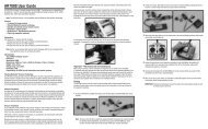
BindingBinding is necessary to program the receiver to the transmitterso that the receiver will only recognize that specific transmitter,ignoring signals from any other sources. If the receiver is notbound to the transmitter, the system will not operate. Duringbinding, the servo’s failsafe positions are stored.The following sequence describes the binding procedure for theJR1221, however, all JR and Spektrum DSM aircraft receiversare bound in the same way.How to Bind1. With the system hooked up as shown, insert the bind plugin the charge plug receptacle. The switch must be a 3-wiretype switch (JRPA001 or JRPA004) to enter the bind modethrough the switch. If a 3-wire switch is not available, installthe male bind plug directly into the receiver bind/datareceptacle and power the receiver through any other openport to enter the bind mode.3. Establish the desired failsafe stick positions: normally lowthrottle and flight controls neutral.REMOVE BEFORE USE2. Turn on the receiver switch. Note that the LED’s on allreceivers should be flashing, indicating that the receiver isready to bind.4. Press and hold the bind button on the back of the transmitterwhile turning on the power switch. The bind lights on thefront and rear of the transmitter should flash and withina few seconds the system should connect. The LED’s onthe receivers should go solid, indicating the system hasconnected.5. Remove the bind plug from the receiver or switch harnessand store it in a convenient place.6. After you’ve programmed your model, it’s important torebind the system so the true low throttle and neutral controlsurface positions are programmed.I-17Note: To bind an aircraft with an electronic speedcontroller that powers the receiver through the throttlechannel (BEC), insert the bind plug into the bind/data portand proceed to Step #2.
ModelMatchThe 12X features patented ModelMatch technology thatprevents the operation of a model if the wrong model memoryis selected. During binding the receiver actually learns andremembers the specific model memory (1 through 50) that thetransmitter is currently programmed to. Later, if the incorrectmodel memory in the transmitter is selected and the receiveris turned on, the model simply won’t operate, preventing apossible crash. Change programming to the correct modelmemory and you’re set to fly.Failsafe FunctionsThe JR R1221 receiver features two types of failsafe: SmartSafeand Preset failsafe.I-18
SmartSafeThis type of fail-safe is especially ideal for most types of electricaircraft and is also recommended for most types of gas- andglow-powered airplanes and helicopters. Here’s how SmartSafeworks.Receiver Power OnlyWhen the JR R1221 receiver only is turned on (no transmittersignal is present) the throttle has no signal output. Thisprevents the arming of the electronic speed control. In glowpoweredmodels, the throttle servo has no input so it remains inits current position. All other channels are driven to their storedfail-safe positions.After ConnectionWhen the transmitter is turned on and after the receiverconnects to the transmitter, normal control of all channelsoccurs. After the system makes a connection, if loss of signaloccurs, SmartSafe drives the throttle servo only to its presetfail-safe position (low throttle) that was set during binding.All other channels hold their last position. When the signalis regained, the system immediately (less than 4 ms) regainscontrol. Any time the transmitter is turned on and operating witha DSM system, the amber light on the rear of the transmitterwill be on solid (not flashing) and the red and blue lights on thetop front of the transmitter will also be on solid (not flashing)indicating the system is outputting signal and operating.Failsafe for JR/SpektrumPreset fail-safe is ideal for sailplanes and is preferred by somemodelers for their glow- and gas-powered aircraft.Receiver Power OnlyWhen the JR R1221 receiver only is turned on (no transmittersignal is present) all channels including the throttle have nosignal output. This prevents the arming of the electronic speedcontrol. In glow-powered models, the throttle servo has noinput so it remains in its current position. All other channels aredriven to their stored fail-safe positions.I-19
After ConnectionWhen the transmitter is turned on and after the receiverconnects to the transmitter, normal control of all channelsoccurs. After the system makes a connection, if loss of signaloccurs, preset fail-safe drives all servos to their preset fail-safepositions. For sailplanes it’s recommended that the spoilers/flaps deploy to de-thermalize the aircraft, preventing a flyaway.Some modelers using powered planes prefer to use this failsafesystem to program a slight turn and low throttle to preventtheir aircraft from flying away. When the signal is regained, thesystem immediately (less than 4 ms) regains control.<strong>Programming</strong> SmartSafe(All JR DSM and Spektrum Aircraft Receivers)During the binding process, the bind plug is left in throughoutthe process and is removed only after the receiver connectsto the transmitter. After the connection is made, confirmedby operating the servos, the bind plug can be removed. Thereceiver is now programmed for SmartSafe.<strong>Programming</strong> Preset Failsafe for JR/Spektrum(JR R1221, JR R1222, JR R921, JR R922, Spektrum AR9000,and Spektrum AR9100 Receivers Only)During the binding process, the bind plug is inserted in thebind port or in the charge jack, and then the receiver is poweredup. The LED’s in each receiver should blink, indicating that thereceiver is in bind mode. Now before binding the receiver to thetransmitter and with the receiver in bind mode, remove the bindplug. The LED’s will still be blinking. With the control sticks andswitches in the desired fail-safe positions, bind the transmitterto the receiver by pressing and holding the bind buttons on theback of the transmitter/module and turning on the transmitter.The system should connect in less than 15 seconds. Thereceiver is now programmed for preset fail-safe.Note: Fail-safe positions are stored via the stick andswitch positions on the transmitter during binding.I-20
Range Testing90 feet (30 paces)Before each flying session, and especially with a new model,it’s important to perform a range check. The 12X incorporatesa range testing system which, when the bind button on thetransmitter is pressed and held, reduces the output power,allowing a range check.Range Testing1. With the model resting on the ground, stand 30 paces(approx. 90 feet) away from the model.2. Face the model with the transmitter in your normal flyingposition and depress and hold the bind button on the backof the transmitter. This causes reduced power output fromthe transmitter.3. You should have total control of the model with the buttondepressed at 30 paces (90 feet).4. If control issues exist, call the Product Support Departmentat 1-877-504-0233 for further assistance.Advanced Range Testing Using a Flight LogWhile the above Standard Range Testing procedure isrecommended for most sport aircraft, for sophisticated aircraftthat contain significant amounts of conductive materials (i.e.turbine-powered jets, some types of scale aircraft, aircraft withcarbon fuselages, etc.) the following advanced range checkwill confirm that all internal and remote receivers are operatingoptimally and that the installation (position of the receivers)is optimized for the specific aircraft. This Advanced RangeCheck allows the RF performance of each remote receiver tobe evaluated and to optimize the locations of each individualremote receiver.I-21
Advanced Range TestingPlug a Flight Log (optional, JRPA145) into the data port in thereceiver and turn on the system (Tx and Rx).Advance the Flight Log until F- frame losses are displayed bypressing the button on the flight log.Have a helper hold your aircraft while he observes the FlightLog data.Standing 30 paces away from the model and helper, face themodel with the transmitter in your normal flying position anddepress and hold the bind button on the back of the transmitter.This causes reduced power output from the transmitter.Have your helper position the model in various orientations(nose up, nose down, nose toward the Tx, nose away fromthe Tx, etc.) while your helper watches the Flight Log notingany correlation between the aircraft’s orientation and FrameLosses. Do this for 1 minute. The timer on the transmitter canbe used here. For giant-scale aircraft, it’s recommended that theairplane be tipped up on its nose and rotated 360 degrees forone minute then record the data. Next place the airplane on itswheels and do a second test rotating the aircraft in all directionsfor one minute.After one minute release the bind button. A successful rangecheck will have less that ten recorded frame losses. Scrollingthe Flight Log through the Antenna fades (A, B, L, R) allowsyou to evaluate the performance of each receiver. Antennafades should be relatively uniform. If a specific antenna isexperiencing a high degree of fades, then that antenna shouldbe moved to a different location.A successful Advanced test will yield the following:• H- 0 holds• F- Less than 10 frame lossesA, B, R, L- Frame losses will typically be less than 100.It’s important to compare the relative frame losses and if aparticular receiver has a significantly higher frame loss value(2X to 3X) then the test should be redone; if the same resultsoccur, move the offending receiver to a different location.I-22
Flight Log - Optional for JR R1221 ReceiverThe Flight Log is compatible with JR R1221 receivers. TheFlight Log displays overall RF link performance as well as theindividual internal and external receiver link data. Additionally itdisplays receiver voltage.After a flight and before turning off the receiver or transmitter,plug the Flight Log into the Data port on the JR R1221receiver. The screen will automatically display voltage i.e.(6v2= 6.2 volts ).Note: When the voltage reaches 4.8 volts or less, thescreen will flash indicating low voltage.JRPA145Using the Flight LogPress the button to display the following information:• A - Antenna fades on internal antenna A• B - Antenna fades on external antenna B• L - Antenna fades on the left external antenna• R - Antenna fades on the right external antenna• F - Frame loss• H - HoldsAntenna fades—represents the loss of a bit of information onthat specific antenna.Typically it’s normal to have as many as 50 to 100 antennafades during a flight.Holds are indicated when 45 consecutive (one right after theother) frame losses occur.This takes about one second. If a hold occurs during a flight,it’s important to re-evaluate the system, moving the antennasto different locations and/or checking to be sure the transmitterand receivers are all working correctly.Note: A servo extension can be used to allow the FlightLog to more conveniently be plugged in without having toremove the aircraft’s hatch or canopy. On some models,the Flight Log can be plugged in, attached and left onthe model using double-sided tape. This is common withhelicopters, mounting the Flight Log conveniently to theside frame.If any single antenna experiences over 500 fades in a singleflight, the antenna should be repositioned in the aircraft tooptimize the RF link.Frame loss—represents simultaneous antenna fades on allattached receivers. If the RF link is performing optimally, framelosses per flight should be less that 20.I-23
Receiver Power System RequirementsWith all radio installations it is vital that the onboard powersystem provides adequate power without interruption to thereceiver even when the system is fully loaded (servos atmaximum flight loads). This becomes especially critical withgiant-scale models that utilize multiple high torque/ highcurrent servos. Inadequate power systems that are unable toprovide the necessary minimum voltage to the receiver duringflight loads have become the number one cause of in-flightfailures. Some of the power system components that affect theability to properly deliver adequate power include: the selectedreceiver battery pack (number of cells, capacity, cell type, stateof charge), switch harness, battery leads, regulator (if used) andpower bus (if used).While JR’s receiver’s minimum operational voltage is 3.5volts, it is highly recommended the system be tested per theguidelines below to a minimum acceptable voltage of 4.8volts during ground testing. This will provide head room tocompensate for battery discharging or if the actual flight loadsare greater than the ground test loads.Recommended Power System Guidelines1. When setting up large or complex aircraft with multiple hightorque servos, it’s highly recommended that a current andvoltmeter (HAN172) be used. Plug the voltmeter in an openchannel port in the receiver and with the system on, loadthe control surfaces (apply pressure with your hand) whilemonitoring the voltage at the receiver. The voltage shouldremain above 4.8 volts even when all servos are heavilyloaded.Note: The optional Flight Log has a built-in voltmeter andit can be used to perform this test.2. With the current meter inline with the receiver battery lead,load the control surfaces (apply pressure with your hand)while monitoring the current. The maximum continuousrecommended current for a single heavy-duty servo/batterylead is three amps while short duration current spikesof up to five amps are acceptable. Consequently, if yoursystem draws more than three amps continuous or fiveamps for short durations, a single battery pack with a singleswitch harness plugged into the receiver for power willbe inadequate. It will be necessary to use multiple packswith multiple switches and multiple leads plugged into thereceiver.3. If using a regulator, it’s important the above tests are donefor an extended period of 5 minutes. When current passesthrough a regulator, heat is generated and this heat causesthe regulator to increase resistance, which in turn causeseven more heat to build up (thermal runaway). While aregulator may provide adequate power for a short duration,it’s important to test its ability over time as the regulatormay not be able to maintain voltage at significant powerlevels over time.4. For really large aircraft or complex models (for example35% and larger or jets), multiple battery packs withmultiple switch harnesses are necessary or in many casesone of the commercially available power boxes/ busses isrecommended. No matter what power systems you choose,always carry out test #1 above making sure that the receiveris constantly provided with 4.8 volts or more under allconditions.5. The latest generation of Nickel-Metal Hydride batteriesincorporates a new chemistry mandated to be moreenvironmentally friendly. These batteries when chargedwith peak detection fast chargers have tendencies to falsepeak (not fully charge) repeatedly. These include all brandsof Ni-MH batteries. If using Ni-MH packs, be especiallycautious when charging making absolutely sure that thebattery is fully charged. It is recommended to use a chargerthat can display total charge capacity. Note the numberof mAh put into a discharged pack to verify it has beencharged to full capacity.I-24
Tips On Using 2.4GHz SystemsWhile your DSM equipped 2.4GHz system is intuitive tooperate, functioning nearly identically to 72MHz systems,following are a few common questions from customers:Q: Which do I turn on first, the transmitter or the receiver?A: It doesn’t matter. If the receiver is turned on first, the receiverstarts scanning the band looking for a signal with its pre-boundGUID. At this time no servo output pulses are present and thethrottle channel doesn’t put out a pulse position, preventingthe arming of electronic speed controllers, or in the case of anengine-powered aircraft, the throttle servo remains in its currentposition. When the transmitter is then turned on, the transmitterscans the 2.4GHz band and acquires two open channels.Then the receiver that was previously bound to the transmitterfinds the GUID (Globally Unique Identifier code) stored duringbinding. The system then connects and operates normally.If the transmitter is turned on first, the transmitter scans the 2.4GHz band and acquires two open channels. When the receiver isthen turned on, the receiver scans the 2.4GHz band looking forthe previously stored GUID; when it locates the specific GUIDcode and confirms uncorrupted repeatable packet information,the system connects and normal operation takes place. Typicallythis takes 2 to 6 seconds.Q: Sometimes the system takes longer to connect andsometimes it doesn’t connect at all - why?A: In order for the system to connect (after the receiver isbound), it must receive a large number of continuous (one afterthe other) uninterrupted perfect packets from the transmitter.This process is purposely critical of the environment, ensuringthat it’s safe to fly when the system does connect. If thetransmitter is too close to the receiver (less that 4 feet) or ifthe transmitter is located near metal objects (metal transmittercase, the bed of a truck, the top of a metal work bench, etc.),connection can take longer, and in some cases connection willnot occur, as the system is receiving reflected 2.4GHz energyfrom itself and is interpreting this as unfriendly noise. Movingthe system away from metal objects or moving the transmitteraway from the receiver and powering the system up again willcause a connection to occur. This only happens during theinitial connection. Once connected, the system is locked in;should a loss of signal occur (failsafe), the system connectsimmediately (4ms) when the signal is regained.Q: I’ve heard that the DSM system is less tolerant of lowvoltage. Is that correct?A: All DSM receivers have an operational voltage range of 3.5to 10 volts. With most systems this is not a problem as, in fact,most servos cease to operate at around 3.8 volts. When usingmultiple high current draw servos with a single or inadequatebattery/ power source, heavy momentary loads can cause thevoltage to dip below this 3.5 volt threshold, thus causing theentire system (servos and receiver) to brown out. When thevoltage drops below the low voltage threshold (3.5 volts), theDSM receiver must reboot (go through the start-up process ofscanning the band and finding the transmitter) and this can takeseveral seconds. Please read the receiver power requirementon page I-24 as this explains how to test for and prevent thisoccurrence. Note the JR R1221 and newly manufactured JR andSpektrum DSM receivers have a new QuickConnect feature that,if a temporary power loss occurs, will reconnect the system inless than .25 seconds. If a power loss or brownout occurs, thereceiver will indicate the power loss by flashing. If you land andthe receiver is flashing, it’s important that you investigate andcorrect the issue that caused the power loss.Q: Sometimes my receiver loses its bind and won’t connect,requiring rebinding. What happens if the bind is lost in flight?A: The receiver will never lose its bind unless it’s instructed to.It’s important to understand that during the binding processthe receiver not only learns the GUID (code) of the transmitterbut the transmitter learns and stores the type of receiver thatit’s bound to. If the bind button on the transmitter is pressed atany time and the transmitter is turned on, the transmitter looksfor the binding protocol signal from a receiver. If no signal ispresent, the transmitter no longer has the correct information toconnect to a specific receiver and, in essence, the transmitterhas been “unbound” from the receiver. We’ve had severalcustomers that use transmitter stands or trays that unknowinglydepress the bind button and the system is then turned on,losing the necessary information to allow the connection to takeplace. We’ve also had customers that didn’t fully understand therange test process and pushed the bind button before turningon the transmitter, also causing the system to “lose its bind.”If, when turning on, the system fails to connect, one of thefollowing has occurred:I-25
The wrong model has been selected in the model memory(ModelMatch).The transmitter is near conductive material (Tx case, truck bed,etc.) and the reflected 2.4GHz energy is preventing the systemfrom connecting (see #2 above).The bind button was unknowingly (or knowingly) depressed andthe transmitter was turned on previously, causing the transmitterto no longer recognize the receiver.Q: Can I use a 3-cell Li-Po pack in my transmitter?A: No. All current JR and Spektrum transmitters are designedto operate using a 9.6-volt transmitter pack. A fully charged3-cell Li-Po pack puts out 12.6 volts. This higher voltage canoverload the power-regulating transistor, causing damageand or failure, possibly in flight. Many of our customers haveexperienced failures using 3-cell Li-Po packs and their use inJR and Spektrum transmitters is highly advised against. The12X system will operate for over 8 hours using the included2000mAh Ni-MH battery.6. Q: How important is it that I test my system using a flightlog?A: For most sport airplanes and helicopters the use of the flightlog is unnecessary. For sophisticated aircraft, especially thosethat have significant conductive materials within the airframe(i.e. jets, scale airplanes, etc.), the Flight Log offers an extrameasure of confidence that all radio components are workingoptimally. The Flight Log is an important tool that allows theconfirmation that the installation (position of the internal andremote receivers relative to the conductive materials in theaircraft) is optimized and that the RF (radio) link is operating atthe highest levels of performance.I-26
Airplane - ACRO ModeThe ACRO mode is intended for powered fixed-wing aircraft.It contains a host of advanced features that are designed toassist the pilot in realizing the full potential of the aircraft. Thesefeatures include:• Up to 5 flight modes• Switch and lever assignability• Triple Rates and Exponentials for Aileron, Elevator andRudder that can be combined or assigned to flight modes• 4 programmable Wing Types (Normal, Flaperon, Delta,4-aileron)• Aileron Differential with two values• V-Tail mixing• Dual Channels for All Primary Flight Controls and Flaps• Dual Throttles (With Independent Trims and ThrottleCurves)• Adjustable Trim Rates (10–100 Trim Steps)• L.S.T. trim—trim can be programmed to affect endpoints orcenter point only• Elevator-To-Flap mixing• Aileron-To-Flap mixing• Governor mixing• Balance mixing allows precise mixing of slave channel tomaster at multiple points• Throttle hold—can be assigned as a kill switch• Aileron-To-Rudder mixing• Throttle Curves (2)• Flap System (With Elevator Trim, Auto Land, Elevator/FlapDelay)• Gyro System (In-Flight Gain Selection of 3 Gains for up to2 Gyros)• Servo Speed (Independent in Both Directions – EliminatesDoor Sequencers)• 8 Programmable Mixers (Includes 5 Multi-Point Mixers)• Programmable Trainer System (Selectable Channels forStudent Control)• Timers- up to three (Stopwatch, Countdown, Integrated)• Servo Monitor (Automatically Renames Channels Accordingto Assignments)• Pitch Curve Mixing for variable pitch propsA-1
Transmitter Identification ACROAntennaGear SwitchElevator D/RHandleMix SwitchFlight Mode SwitchFlap SwitchAUX 2 SwitchRudder D/R SwitchLeft Trimmer/TrainerSwitchAUX 4 KnobAUX 5 KnobAileron D/R SwitchLeft Side LeverRight Side LeverThrottle/Rudder StickRight Trimmer/TrainerSwitchAileron/Elevator StickThrottle TrimElevator TrimRudder TrimAileron TrimPower Switch<strong>Programming</strong> ButtonsRolling selectorLCD ScreenA-2
Rudder D/RHandleAUX 6 KnobThrottle Spring Tension CoverElevator Spring Tension CoverAUX 7 KnobLeft SliderRight SliderTrainer/Transfer/PC Interface JackBind/Range Check ButtonRudder Spring Tension CoverAileron Spring Tension CoverCharge JackBattery DoorA-3
System ModeSystem mode contains the foundational programming that isnormally only used when first setting up a model. System modefunctions include: model select, model name, model reset,wing type, etc.—functions that are typically set once duringsetup and then are seldom changed or adjusted. Below, andthroughout this section, the functions are in the order that theyappear in the System Mode List.To Enter System ModePress ENT and hold while turning on the transmitter.The screen should appear as shown above.SYSTEM MODE LISTSystem mode contains the follow screens:84: Model SEL Model Select Page A-681: MDL Name Model Name Page A-828: MDL Reset Model Reset Page A-989: Type SEL Type Select Page A-1085: MODULAT Modulation Page A-11(12X MV system only)93: Freq SEL Frequency Select Page A-12(12X MV system only)83: Trim SYS Trim System Page A-1391: STK Pos SW Stick Position Switch Page A-1592: FM Name Flight Mode Name Page A-1686: Transfer Model Transfer Page A-1797: Warning Warning Page A-1998: Settings Settings Page A-2017: Device SEL Device Select Page A-2122: Wing Type Wing Type Page A-27A-4
Function ModeFUNCTION MODE contains programming functions that areused to complete the setup and then used to adjust and finetunehow the model flies. Below, and throughout this section,the functions are in the order that they appear in the FunctionList.To Enter Function ModePress the LIST button after the transmitter is powered-up toobtain the FUNCTION LIST.Function Mode ListFunction mode contains the follow screens:11: REV. SW Reverse Switch Page A-3112: TRVL ADJ. Travel Adjust Page A-3113: D/R & EXP Dual Rate and Exponential Page A-3215: Sub Trim Sub Trim Page A-3316: THRO Hold Throttle Hold Page A-3318: THRO CURV. Throttle Curve Page A-3424: SRV. Speed Servo Speed Page A-3531: Snap Roll Snap Roll Page A-3632: DIFFEREN. Differential Page A-3733: Balance Balance Page A-3844: Gyro SENS Gyro Sensor Page A-3945: Governor Governor Page A-4062: AILE- RUDD Aileron to Rudder Mix Page A-4163: ELEV- FLAP Elevator to Flap Mix Page A-4264: RUDD- A/E Rudder to Aileron/Elevator Mix Page A-4366: FLAP SYS. Flap system Page A-4451: PROG. MIX1 Program mix 1 Page A-4652: PROG. MIX2 Program mix 2 Page A-4653: PROG. MIX3 Program mix 3 Page A-4654: PROG. MIX4 Program mix 4 Page A-4655: PROG. MIX5 Program mix 5 Page A-4656: PROG. MIX6 Program mix 6 Page A-4657: PROG. MIX7 Program mix 7 Page A-4658: PROG. MIX8 Program mix 8 Page A-4667: AILE-FLAP Aileron-To-Flap mix Page A-5468: PIT. CURV Pitch Curve Page A-5575: Monitor Monitor Page A-5876: MIX MON Mix Monitor Page A-5877: Fail Safe Fail Safe Page A-58.5(12X MV system only)78: Trainer Trainer Page A-5987: Timer Timer Page A-60A-5
To Select a Model Memory1. In the SYSTEM MODE, highlight and select Model SELusing the rolling Selector.2. Use the rolling Selector to highlight MODEL then press theroller and select the desired model number to be used.3. Return to the SYSTEM Menu by pressing the LIST button.Model CopyMaking a backup copy of the model memory protects againstlosing the original program and also allows one to experimentwith the original program, knowing that the original settingscan be restored by copying the backup copy back to the originalmodel memory.To Copy a Model to Another Internal Memory1. In the SYSTEM MODE, highlight and select Model SELusing the rolling Selector.2. Use the rolling Selector to highlight Select then press theroller to access Model Copy.3. Rotate the roller to select the desired model memory thatyou wish to copy the current program to (1-50).4. Press the roller to select the highlighted model that youwish to copy to.5. Press the COPY button to copy the current model list aboveto the selected model listed below.6. Return to the SYSTEM Menu by pressing the LIST button.Note: The model memory that is copied to will bereplaced with the current model memory programming. Itis recommended that a model memory that is not beingused be selected to “copy to,” as the information in thatmemory will be erased and replaced with the currentmodel memory during copying.A-7
81: Model NameThe model name screen allows each model to be given up to asixteen-digit name or number. This is convenient for identifyinga model. The model’s name will appear on the main info screen.To Name a Model1. In the SYSTEM MODE, highlight and select MDL Nameusing the Selector.2. Position the cursor using the roller (indicates where thenext character will be placed) at the beginning of themodel name. Press the Selector to obtain a list of availablecharacters.3. Highlight and select the desired character to form the modelname. After the character is selected, rotate the Selector toposition the cursor where the next character is to be placedand press the Selector to obtain the character list again.Repeat until the model name is completed.4. Return to the SYSTEM Menu by pressing the LIST button.A-8
28: Model ResetModel Reset is used to reset all programming to factory defaultsettings. When setting up a new model it is important toreset all parameters to their default or factory settings beforeproceeding with any other programming. This is to ensure thatthere are no programming values or functions active from aprevious model or programming session.To Reset a Model Memory1. In the SYSTEM MODE, highlight and select MDL Resetusing the Selector.2. Press the CLR button that is next to RESET on the display.3. Press the lowermost button next to YES on the display toreset all data for this model.4. Return to the SYSTEM Menu by pressing the LIST button.A-9
89: Type SelectType select allows the model type to be selected. Model typesinclude HELI (helicopter), ACRO (airplane) and GLID (glider).Note: When changing model types, the programminginformation will be reset to the factory default setting,losing the previous settings.To Select a Model Type1. In the SYSTEM MODE, highlight and select Type SEL usingthe Selector.2. Highlight and select ACRO using the Selector and press theselector to access the ACRO mode.3. Return to the SYSTEM Menu by pressing the LIST button.A-10
85: Modulation - (12X MV System only)Note: This function is only available on the 12X MVversion and only when the TSM-72A 72MHz module isplugged in.Important: When the 72MHz module is plugged in andthe system is turned on, the antenna must be attached.Operating the 72MHz module without the antenna attachedcould overload the internal transistor causing a failure.Warning: Only the JR TSM-72A and JRM2.4 modulesare compatible with the 12X MV. Do not install a standardtypeJR, Spektrum or other branded module in the 12X asdamage will occur.The 12X MV version radio system allows the RF module to bereplaced allowing the system to operate on 72MHz or 2.4GHz.Note that the transmitter automatically detects which module isinstalled and modifies the accessible programming appropriateto the module selected.The Modulation screen (code 85) allows the selection ofmodulation for 72MHz receiver types. Modulation typesavailable are:Note: APCM - JR’s newest version PCM (not available inthe U.S.)• SPCM - Most currently available JR PCM receivers use thistype of modulation• ZPCM - Compatible with older JR receivers• PPM - FM modulationNote: It’s important to select the modulation to matchthe receiver type. JR receivers have the modulation typeprinted on the receiver.To Program a Modulation Type1. In the SYSTEM MODE, highlight and select TypeMODULAT. using the Selector.2. Highlight and select the currently selected modulation type(APCM) using the Selector and press the selector to accessall available modulation types (APCM, SPCM, ZPCM,PPM).3. Rotate the roller to highlight the desired modulation typethen press the roller to select the modulation type.4. Return to the SYSTEM Menu by pressing the LIST button.Note: APCM modulation is only available in Japan marketreceiversA-11
93: Frequency Select - (12X MV system only)Note: This function is only available on the 12X MVversion and only when the TSM-72A 72MHz module isplugged in.Important: When the 72MHz module is plugged in andthe system is turned on, the antenna must be attached.Operating the 72MHz module without the antenna attachedcould overload the internal transistor causing a failure.Warning: Only the JR TSM-72A and JRM2.4 modulesare compatible with the 12X MV. Do not install a standardtype JR, Spektrum or other branded module in the 12X asdamage will occur.The 12X MV version radio system allows the RF module to bereplaced allowing the system to operate on 72MHz or 2.4GHz.Note that the transmitter automatically detects which module isinstalled and modifies the accessible programming appropriateto the module selected.The Frequency Select function allows the selection of 72MHzchannels 11 through 60 when the 72MHz module is installed.This screen displays the channel and corresponding frequency.To Select a Frequency1. In the SYSTEM Menu, highlight and select Type FREQ SEL.using the Selector.2. Highlight and select the currently selected channel usingthe Selector and press the selector to access all availablechannels.3. Rotate the roller to select the desired channel then press theroller to select that channel. The selected channel will bedisplayed on the main screen every time the transmitter isturned on and RF-ON or RF-OFF will be displayed on theleft side of the screen. To transmit press RF-ON.A-12
83: Trim SystemThe Trim System function adjusts the sensitivity of the 12Xtrim levers and the Flap and Aux trimmers. The standard digitaltrims are adjustable from 0–10 with 10 being the coarsestadjustment and 0 being trim off. Adjusting the digital trimvalues has no effect on the total trim travel, however, it affectsthe resolution of each trim input. When the value is set to 10,each click of trim adjusts the servo output by 10ms and thereare only 10 trim increments from center to each end. When setto 5, the output is changed 5ms per trim step and there are 20trim increments from center to each end. When set to 1, eachclick of trim changes the servo output by 1ms and there are100 trim increments. When set to 0 the trim levers cease tofunction effectively, turning off the trim function. The Flap andAux Trimmers are adjustable from 0 to 200 and can be turnedon/off. When adjusted to above 100% the trimmer functions asa two- or three-position switch. Reducing the value increasesthe number of output positions. The trimmers can also be set tofunction as a momentary switch by selecting ON under Momentfor either or both trimmers. When adjusting the digital trims(AILE, ELEV, RUDD), the total trim travel does not change –only the number of increments (beeps) changes, which makesfor finer or coarser trim movements. When adjusting the analogthrottle trim, however, the total trim travel is actually reducedwhen set to less than 100%. Use a fairly coarse setting, such asthe factory default 4, when test flying a model for the first flightsin order to be able to trim it quickly; use a finer setting, such as3–1, for final precision trimming.When adjusting the digital trims (AILE, ELEV, RUDD), the totaltrim travel does not change – only the number of increments(beeps) changes, which makes for finer or coarser trimmovements. When adjusting the analog throttle trim, however,the total trim travel is actually reduced when set to less than100%.Use a fairly coarse setting, such as the factory default 4, whentest flying a model for the first flights in order to be able to trimit quickly; use a finer setting, such as 3–1, for final precisiontrimming.L.S.T. Trim (Limited Standard Trim)The L.S.T. trim feature has two options: L.S.T. and normal. Innormal, when making trim changes using the aileron, elevatoror rudder digital trims, the center as well as the endpoints isaffected by the trim values. The right trim causes the center,the right endpoint and the left endpoint to all shift to theright. When L.S.T. is activated, only the center position istrimmed. The center is shifted to the right but the endpointsare not affected. This is useful for aircraft that have a hard stopendpoint to prevent over-travel caused by trim or if it’s desiredto have trim changes not affect the total roll pitch or yaw rate.A-13
To Adjust the Trim Rates1. Highlight and select TRIM SYS. in the SYSTEM MODE toacquire the Trim System function.2. Highlight and select the trim that is to be changed anduse the Selector to set a value of 1–10 (1 = finest, 10 =coarsest).Note: The Flap and AUX trims are adjustable from 0 to200 and can be turned off or on by selecting On or Off.Moment in the trim function is used to make the FlapTrimmer and Aux Trimmer work as a Momentary on-offswitch, if Moment is turned ON, pressing the trimmerand holding will move the assigned function and, whenreleased, will return it to the original position. If using anapplication that requires the Moment function to be turnedON, also select the Trimmer to OFF. These trimmers canbe assigned to the aux channels in the Device Selectfunction.3. Repeat for other trims as desired.To Select the L.S.T. Trim Function1. Highlight and select the desired channel (AILE, ELEV orRUDD) next to (TYPE) L.S.T. and press the roller to selectL.S.T. or NORM.2. Repeat for other channels as desired.A-14
91: Stick Position SwitchThe Stick Position Switch function allows the throttle, aileronelevator or rudder stick positions to be preprogrammed to turnon/ off mixes, change throttle curves, change differential rates,start a timer and other functions. An example of this would beto have a smoke system that turns off below 25% throttle toprevent low throttle flameouts. Four stick position programs areavailable and one or more can be assigned to various mixes orfunctions. The stick position that turns the Stick Position switchoff /on is selectable as well as the direction to turn on/ off. Alsoa symmetrical option is available that allows the function tobe turned on with a preprogrammed equal right or left (up ordown) stick position.To Program a Stick Position Switch1. In the SYSTEM MODE, highlight and select STK PosSWusing the Selector.2. Highlight the desired Stick position switch that you desireto use (SPS0, SPS1, SPS2, or SPS3) and press the roller.All four are the same.3. Select the desired channel that will be used to trigger theStick position (Throttle, Aileron, Elevator, and Rudder).4. Rotate the roller to select POS and adjust to the desiredvalue that you wish to have the mix function turn off/ on.0 = center, L100= Left full stick travel, etc. Note ON/ OFFis displayed at the top of the screen and when moving thestick this will indicate that the function is working.5. Use the roller to select ON and select Low/ High or Right /Left to access the desired direction that the function willturn on/ off.6. A symmetrical function is available that allows the stickposition to be turned on/ off as the stick is displacedsymmetrically in either direction. It’s necessary to firstprogram a value in the POS, then highlight the SYMand activate it using the roller. The center can now beprogrammed to turn on or off by selecting the ON andhighlighting Low/ High or Right /Left.Note: The above procedure establishes the base forturning on/ off mixes, change throttle curves, changesdifferential rates, etc. To program the stick position, it’snecessary to go to the desired function in Function modeand select SPS0, SPS1, SPS2 or SPS3 under SW (switch)in that specific function.7. Return to the SYSTEM Menu by pressing the LIST button.A-15
92: Flight Mode NameThe Flight Mode Name program allows each flight mode to becustom named with up to six characters. On the main screenan abbreviated (short name of up to four characters) will beautomatically displayed when that flight mode is selected.Examples for flight mode names may include 3DRATE, LAND,ROLLER, etc.To Program a Flight Mode Name1. In the SYSTEM MODE, highlight and select FM Name usingthe Selector.2. Highlight the desired flight mode character position usingthe roller, then press the roller to access the list of theavailable characters.3. Highlight and select the desired character to form theflight mode name. After the character is selected, rotate theSelector to position the cursor where the next character isto be placed and press the Selector to obtain the characterlist again. Repeat until the flight mode name is completed.4. Use the roller to highlight the * below the flight mode nameand press the roller to select up to four characters fromthe above flight mode to be automatically displayed on themain screen when that flight mode is selected.5 Return to the SYSTEM Menu by pressing the LIST button.A-16
86: TransferThe TRANSFER function allows one 12X transmitter to transfer amodel memory for a specific model to another 12X transmitter.This function is also used to transfer a model memory to theincluded PC Data Transfer allowing unlimited model memorystorage and backup of your model’s programming. The Transferfunction is also used to receive data from another 12X or fromthe PC Data Transfer.Note: The sending and receiving transmitters mustboth be 12X’s or the PC Data Transfer device and a 12X.Transfer is not possible with any other system.Preparing the 12X to Receive a Model Transfer1. Hold the ENT button while plugging the Trainer cord intothe back of the transmitter to obtain the SYSTEM List. Plugthe other end of the DSC cord into another 12X transmitterwhile holding the ENT button and after the following,prepare that transmitter for transfer send as describedabove.2. Highlight and select TRANSFER in the SYSTEM Menu toobtain the Transfer display.3. If RECEIVE is already displayed, continue with the next step.If TRANSMIT is displayed, highlight and select TRANSMIT,changing it to RECEIVE.4. Select the model memory that is to receive the data byhighlighting and selecting the model name/memory numberand then scrolling to and selecting the model memory thatis to receive the data. Select an unused model memory ora memory that contains data for a model that is no longerneeded as the data in this model memory will be replacedby the model memory that is transferred and will bepermanently lost.Note: The receiving model name/memory number cannot be the currently selected model. If you wish to receivea model in the currently selected model name/memorynumber, go to the model select function and select adifferent model, then reenter the transfer function andfollow the instructions above.5. Press START on the left side of the display. Stand-byappears at the bottom of the display indicating that thesystem is ready to receive data. Follow the next steps toprepare the sending transmitter for memory transfer.A-17
Preparing the 12X to Send a Model Transfer1. With the other end of the trainer cord plugged into thesending 12X transmitter in SYSTEM List as described instep 1 above, highlight and select TRANSFER (code 86) inthe SYSTEM Menu to obtain the Transfer display.2. The model to be transferred must be the currently selectedmodel. If the model to be transferred is not currentlyselected, see Model SEL in the SYSTEM Menu to select themodel to be transferred.3. When the receiving 12X is ready, press START on the leftside of the display. The data for the currently selected modelis transferred to the receiving device.A-18
97: WarningThe Warning function can be programmed to sound an alarm ifa selected flight mode, switch positions or throttle stick positionis in an inappropriate position when the transmitter is turnedon. For example if the gear switch is in the retraced positionand the transmitter is turned on, an alarm can sound warningthat the switch will cause the gear to retract if the receiver isturned on. Or if the throttle is above a preprogrammed positionwhen the transmitter is turned on an alarm will sound warningof an unsafe throttle position for startup. Stick positions canalso be programmed to sound alarms. See page A-15 forprogramming stick position switches. Note that during thewarning no signal is being transmitted. The Throttle stick isdefaulted with a warning above 10% and an alarm will soundand no signal will be transmitted if the throttle is above 10%and when the transmitter is turned on. The warning function isavailable for the following:• Flight Mode 0 • Flight Mode 1• Flight Mode 2 • Flight Mode 3• Flight Mode 4• Flap Switch Normal• Flap Switch Mid • Flap Switch Land• Gear Switch• Mix Switch• Stick Position Switch 0 • Stick Position Switch 1• Stick Position Switch 2 • Stick Position Switch 3• Throttle Stick Position • Aileron 1• Aileron 2• AUX2 up• AUX2 middle• AUX2 downTo Program a Warning1. In the SYSTEM MODE, highlight and select Warning usingthe Roller.2. Highlight the desired flight mode, switch position or stickposition switch (SPS) then press the roller to turn onoff that function as a warning. Note that it is possible toactivate multiple functions as a warning.Note: To select a Stick Position Switch as a warning itis first necessary to activate the stick switch. See StickSwitch Position Code 91 on page A-15 for more details.3. If a throttle stick position is desired as a warning, highlightINH next to throttle and press the roller to activate thethrottle stick position. Rotate the roller to select POSand adjust to the desired value that you wish to have thewarning sound. Note that 0= low throttle, 50 = 50% throttle,etc. ON/ OFF is displayed at the top of the screen and whenmoving the stick this will indicate that the function is on/off. The throttle stick position warning comes default set toactive with a position of 10.4. Use the roller to select ON and select Low or Hi to have thealarm sound above or below the POS position.5. Return to the SYSTEM Menu by pressing the LIST button.A-19
98: SettingsThe Settings program allows the screen backlight to beturned on/ off/ or placed in auto (sleep) mode. This functionalso allows the audible beeper to be turned on or off. Thesefunctions are defaulted to Backlight Auto and Silent Mode off.To Change Transmitter Settings1. In the SYSTEM MODE, highlight and select Settings usingthe Selector.2. Highlight the desired function. Display backlight or SilentMode using the roller then press the roller to access andchange the settings.3. Return to the SYSTEM Menu by pressing the LIST button.A-20
17: Device SelectDevice Select is used to activate some of the more advancedfeatures of the 12X. The Device SEL function is used to activate/inhibit the following:• Flight Modes (5 in total)• Throttle Hold• Flap Trim• Trim Common• Switch, Lever and Knob Assignments• Activate/Inhibit Switches/Channels• Activate/Inhibit the Governor• Activate/Inhibit the Gyro• Activate/Inhibit the Pitch Curve Function• Activate/Inhibit the Flap System• Assign Functions and Channel to the DesiredSwitch Knob or LeverEach of these options is described as follows.Flight ModesA Flight Mode represents an aircraft configuration (Dual Rate/Expo, program mixes, Aileron Differential, Flap System, GyroSystem, etc.) that is programmed to optimize the control systemto assist the pilot and the aircraft in performing a specific typeof maneuver. Up to 5 flight modes are available in the 12X.The objective of programming Flight Modes is to provide theability to select a switch position to activate a collection ofsettings that are optimized to perform a maneuver. An aerobaticaircraft, for example, may be set up such that the Flight Modeswitch in its 1st position (FM 0) configures the aircraft forprecision flying; positioning the switch in its 2nd position (FM1) sets the aircraft up for snap rolls; and positioning the switchin its 3rd position (FM 2) sets the aircraft up for aggressive3D flight. Flight Modes could just as easily represent aircraftsettings for Take Off, Flying, and Landing for a turbine-poweredjet aircraft. Flight Modes can make the pilot’s job easier byconfiguring and optimizing the aircraft to do different things byflipping a single switch.Most of the functions found in the 12X that are switchselectable including programmable mixers, throttle curves,differential, gyro settings, servo speed, etc. can be assignedto one or more Flight Modes. This provides the ability to haveup to 5 completely different aircraft configurations that areselectable in flight using switches.Five Flight Modes are available in the 12X system. When 3Flight Modes are activated, they are selected during flight byusing one of six 3-position switches (Flight mode switch,Rudder D/R switch, Flap switch, Elevator D/R switch, Aux 2switch, Aileron D/R switch, or Inhibit). To activate the 2 Extraflight modes (5 flight modes in total) the 4th and 5th flightmodes are assigned to one of the following switches (Mixswitch, Elevator D/R switch, Gear switch, Aileron D/R switch,one of the stick position settings (SPO0-SPO3), or Inhibit).Flight mode switches are selected and activated in the DeviceSEL function in the System menu. Once Flight Modes areactivated, the pilot has a choice of using the Flight Mode switchto select up to 5 Dual Rates and Exponential settings for eachof the primary controls (ELEV, AILE, RUDD), or Dual Ratesand Exponential settings may continue to be controlled by the3 individual Dual Rate switches. All other functions that canbe activated by a switch can be assigned to 1 or more FlightModes when Flight Modes have been activated.A-21
To Activate Flight Modes1. From SYSTEM Mode List, highlight and select DeviceSELusing the Selector.2. Using the Selector, highlight and select INH next to FLIGHTMODE. When selected, 7 options appear: (Flight ModeSW, Rudder D/R SW, Flap SW, Elevator D/R SW, Aux 2 SW,Aileron D/R SW, or INH) Highlight and select the desiredflight mode switch.Once Flight Modes have been activated, FLAP TRIM and TRIMappears on the display.3. To activate the two extra flight modes, using the Selector,highlight and select INH next to EXTRA. When selected,8 options appear: MIX SW, Elevator D/R SW, GEAR SW,Aileron D/R SW, SPO0, SPO1, SPO2, SPO3, or INH)Highlight and select the desired EXTRA flight mode switchto activate the additional two flight modes.A-22
Throttle HoldThe throttle hold function is normally used as a kill switchfor glow-powered airplanes or as a safety/ arming switchfor electric-powered aircraft. It can also be used to preseta programmed throttle position. For example with electricsailplanes it can be used to give full power when the switchis activated. The throttle hold function switch position anddirection is assigned in Device Select. The actual programmingof the throttle hold position is done in Code 16 Throttle Holdscreen in the Function mode (see page A-33).Note: Throttle hold is defaulted to the mix switch.To Assign Throttle Hold to a Switch1. In Device Select, highlight and select Throttle Hold usingthe Roller.2. Using the Selector, highlight and select MIX SW nextto THRO Hold. When selected, 12 switch options anddirections appear: Highlight and select the desired throttlehold switch and direction.A-23
Flap Trim1. The digital FLAP TRIM lever is located on the front rightface of the transmitter and is accessed with your rightindex finger. Flap Trim may be activated or deactivated inthe Devic.SEL function by using the Selector to highlighteither ON or OFF and pressing the Selector. The flap trim isdefaulted to ON.Ordinarily this switch should be turned OFF, even if the aircrafthas flaps or dual ailerons, The 12X provides other means ofcontrolling flaps and disabling this switch will help prevent anout-of-trim condition if flaperons are used and the trim lever isaccidentally moved.A-24
TrimThe Trim function can be toggled between COM (common)and F.M. (Flight Mode) by pressing the Selector when COMor F.M. is highlighted. In the COM mode, the digital trims forElevator, Ailerons, and Rudder are common or shared in allFlight Modes. If a trim change is made in any flight mode, thetrim in all flight modes are also changed (common trims in allflight modes). If F.M. is selected in Stunt Trim, the 12X storesthe digital trim positions independently for each Flight Mode.This allows the aircraft to be independently trimmed in eachflight mode and when that flight mode is selected the previouslyset trim value for that flight mode is active. This is a very usefulfeature if switching between Flight Modes causes the aircraft’strim to change, such as when flaps are deployed by one of theFlight Modes causing the aircraft to have a pitch change. In thiscase, the pilot can simply use the Elevator digital trim to trimthe Elevator to correct the pitch up tendencies when the flapsare deployed using a flight mode. Selecting each Flight Modebrings in a corresponding set of trims, allowing the aircraft tobe independently trimmed for each flight mode during flight.Note: When Trim is set to FMOD, be aware during thefirst flight and remember that the aircraft will need to betrimmed using the digital trims for Aileron, Elevator andRudder for each Flight Mode selected during flight. If theaircraft is badly out of trim, remember that when switchingfrom flight modes each flight mode will require trimming.A-25
Switch AssignmentsThe 12X provides the ability to change the standard defaultswitch assignments for the GEAR, FLAP, AUX2, AUX3, AUX4,AUX5, AUX6, and AUX7 channels. Changing the switchassignments is a matter of preference. The standard switchassignments may be changed in the Devic.SEL functioncontained in the SYSTEM MODE.To Change One or More Switch Assignments1. In the Devic.SEL function, use the Selector to highlightand select the desired channel to the right of GEAR, FLAP,AUX2, AUX3, AUX4, AUX5, AUX6 or AUX7.2. Once a switch is selected, a list of available switches isgraphically displayed. Highlight and select the desiredswitch with the Selector.3. Repeat for as many switches as desired.Activate/Inhibit ChannelsThe 12X provides the ability to activate, inhibit or programchannel 5 (Gear), channel 7 (Aux2) and channel 8 (AUX 3) tooperate as a Governor, Gyro or Pitch function.Note: Inhibiting a channel is necessary when auxiliarychannels are used as dual primary flight controls, suchas using 2 channels/servos for 2 Ailerons or 2 servos/channels to operate the Elevator or Rudder. In thisinstance, the auxiliary channels are no longer to beoperated by their auxiliary switches but rather by theElevator and Rudder sticks and must be inhibited in theDevice Select function.Note: If any of the channels identified above are to beused as a 2nd channel for a primary flight control (AILE,ELEV, RUDD, FLAP), then be sure to Inhibit (INH) theswitches for the channels in this function or they will notbe available to use as a second control channel.Note: When SYS appears next to FLAP, the FLAP SYSTEMfunction will appear in the FUNC.LIST (described later).If the aircraft is equipped with flaps, or equipped withFlaperons that are actually going to be used as flaps thenSYS should be set next to FLAP.Note: When GYR appears, the Gyro Function will appearin the FUNC.LIST (described later on page A-38). Twogyro programs are available.Note: When GOV appears, the Governor Function willappear in the FUNC.LIST (described later on page A-38).Flight modes must be active for this function to beavailable.Note: When PIT appears, the Pitch Function will appear inthe FUNC.LIST (described later on page A-55).1. If GEAR, FLAP, AUX2, AUX3, AUX4, AUX5, AUX6 or AUX7are to be used as a 2nd primary flight control, then inhibitthe corresponding switch by highlighting ACT along theright side of the display; press the roller to select INH.A-26
22: Wing TypeWing TypesThe Wing Type function provides for 4 different wing types(NORMAL, FLAPERON, DELTA and 4- Aileron).NORMAL wing type is used when only the Aileron channel isto be used to control ailerons, either with 1 servo, or multipleservos connected through a Y-harness to the aileron channel.FLAPERON is typically used when each Aileron is controlled bya separate servo that is on separate channels and there are noother flaps on the aircraft. Setting the wing type to FLAPERONalso makes available the Aileron Differential and Elevator-to-Flap mixing functions in the FUNC.LIST (described later).DELTA is used with Delta wing aircraft (also referred to asElevon). With Delta wing type the Ailerons and elevator aremixed giving roll and pitch control for Delta wing airplanes.4-AILERON is used in aircraft where two servos are used tooperate the right aileron and two servos are used to operate theleft aileron. In this configuration each servo is independentlyadjustable for sub trim and travel adjust. A balance function isalso available (page A-38) that allows the servo output to bematched throughout its travel preventing binding due to linkagegeometry inaccuracies.V-Tail MixV-Tail The Wing Type function provides programming foraircraft that have a V-Tail configuration where the 2 tail controlsurfaces are used for both Elevator and Rudder control.Dual Flight ControlsDual Control FunctionsWing Type allows Dual Aileron, Dual Elevator, Dual Rudderand Dual Flap functions to be activated. This function isused when two servos are used to drive the primary controlsurfaces allowing the independent adjustment of for subtrim and travel adjust of each channel. A balance function isalso available (page A-38) that allows the servo output to bematched throughout its travel preventing binding due to linkagegeometry inaccuracies.Note: To access Dual Flaps it is necessary to assign theFlap to SYS (system) in Device Select. When Dual Flapsare activated, Aileron-to-Flap mixing becomes available inthe function list (page A-54).Note: Dual ailerons is a very important commonly usedfunction because a large number of sport and aerobaticaircraft use 2 servos and 2 channels to operate theAilerons, providing the ability to utilize Aileron Differentialand to allow precise independent adjustment of sub trimand travel adjust for each aileron.If the aircraft has flaps that are separate from the Ailerons,the Dual aileron wing type and (activating dual flaps) isrecommended.Twin Engine ControlThe Wing Type function contains the Twin Engine (Twin E.)feature, which allows for setting up a 2nd throttle channel fora second engine, complete with its own independent sub trim,travel adjust and separate trims and throttle curves.A-27
Wing TypeTo Program a Wing Type1. Highlight and select Wing Type in the System Mode Listusing the roller.2. Use the roller to highlight Wing then select the wing typethat is appropriate for your aircraft.Normal- If the Aileron channel only is used to control bothailerons, either with a single servo or with 2 servos connectedtogether via a “Y” harness, then the NORMAL wing type shouldbe selected. Also use NORMAL if the aircraft has flaps that areseparate from the ailerons; if two aileron channels are used,activate the Dual aileron channel listed below.Flaperon- If 2 channels are to be used to control the Aileronsand the aircraft does not have separate flaps, select FLAPERONas the wing type. Plug the right Aileron into the Aileron channel(Ch2) and plug the left Aileron servo into the FLAP or AUX1channel (Ch6) of the receiverNote: If the ailerons are not going to actually be usedas flaps, inhibit the FLAP Switch and FLAP TRIM inthe Devic.SEL function in the SYSTEM Menu. This willeliminate having a severe out-of-trim condition if the FLAPSwitch or FLAP TRIM is accidentally moved.DELTA- If you have a Delta wing aircraft then select DELTA inwing type. This will mix the aileron and elevator functions toprovide roll and pitch control for these types of aircraft. Plug theright control surface into the aileron channel (CH2) and plugthe right surface into the elevator channel (CH3).4-Aileron- If your airplane is equipped with two servos for theright aileron and two servos for the left aileron, then select the4- Aileron option. Right aileron servos plug into channel 2 andchannel 7. Left aileron servos plug into channel 5 and channel8. Each servo is independently adjustable for sub trim andtravel adjustment and the digital trim is active for all servos.A-28
V-Tail1. If the aircraft has a V-tail configuration, highlight INH nextto V-tail in the Wing TYPE function and press the rolleruntil ACT appears. Plug the right Elevator servo into theElevator channel (Ch3) and plug the left Elevator servo intothe Rudder channel (Ch4).Dual Channels1. To assign a 2nd channel to Ailerons, Elevator, Rudder orFlaps, highlight and select INH under the desired channelon the Mate line of the Wing TYPE display and a list ofavailable channels is displayed.Note: Channels/Switches must be inhibited (INH) in theDevic.SEL function before they will appear in the list as anoption to be used as a Dual channel. The Flap SYS mustbe selected in the Deivc.SEL screen to access the DualFlap function.2. Highlight and select the channel that is to be the Mate(slave) to the control channel represented above it. Plug the2nd control surface servo into the channel selected as theMate.A-293. INH will appear on the Trim Line of the display directlybeneath the channel just selected. This means that thecorresponding digital trim (FLAP TRIM or AUX TRIM)located next to the FLAP and AUX2 switches can be usedas additional trims. However, the additional trims do notfunction in the same fashion as regular trims. Instead,they trim the controls such that both channels move in thesame direction – like reflexing both Ailerons or in the caseof Elevator halves, the Elevators would move in oppositedirections. As a result, these additional trims should remaininhibited unless there is a special need for them. If changedto ACT, the corresponding trim switch (Right Trimmeror Left trimmer) will become active. If set to INH theseadditional trim switches are inactive. Normal trims continueto work regardless of the settings.
Twin EngineIf the aircraft is equipped with twin engines, the Twin Enginefeature (Twin E.) may be used for a 2nd throttle channel with anoptional separate digital trim.1. Highlight and select INH next to Mate under Twin ENGIN.A list of available channels will appear. Select the desiredchannel to be used as the second throttle channel. Plug theLeft engine throttle servo into the channel selected as theMate. Plug the Right engine throttle servo into the throttlechannel (Ch 1).2. If the second throttle channel is to be trimmed using eitherthe normal throttle trim lever or a separate trim lever,highlight and select INH next to Trim under Twin E. causingthe setting to change to ACT. When set to ACT, the 2ndthrottle servo can be trimmed with the normal throttle trim.Function ModeThe Function Mode contains programming that is used tocomplete the setup and then to adjust the aircraft’s flightcharacteristics. Functions include Servo Reversing, TravelAdjust, Dual Rate and Expo, Sub Trim, Servo Speed,Programmable Mixes, Trainer and Timer functions, etc. Manyof these functions are frequently used to adjust the flightcharacteristics during setup and at the field.To Enter the Function Mode ListWith the transmitter on Press LIST and the Function list willappear.A-30
11: Servo ReversingThe servo reverse screen allows the direction of each servo tobe selected.To Program Servo Reverse1. Highlight and select REV.SW in the FUNC.LIST to obtain theservo reversing display.2. Use the Selector to highlight and select those channelsthat need to be reversed. Pressing the Selector toggles thechannel between Normal and Reverse.12: Travel AdjustTravel Adjust allows the independent adjustment of servo travelfor each direction of servo travel.To Program Travel Adjust Values1. Highlight and select TRVL ADJ. in the FUNC.LIST to obtainthe Travel Adjust display.2. Use the Selector to highlight and select each channel andadjust the travel in each direction by rotating the Selector.The direction of travel is changed by moving the stick/switch/lever in the desired direction to highlight L/R, U/Dor +/-.A-31
13: Dual Rate and ExponentialThree dual and exponential rates are available and are selectablevia flight modes or selected switches.Note: If extra flight modes are activated, up to 5 dual andexponential rates are available. Dual and Expo rates areindependently adjustable in each direction by moving theappropriate stick in the desired direction.To Program Dual Rate and Exponential Values1. Highlight and select D/R & EXP in the FUNC.LIST to obtainthe Dual Rate and Exponential display.2. Highlight and select the desired channel (Aileron, Elevatoror Rudder), noting that 3 sets of values will be displayed foreach channel – Aileron, Elevator and Rudder.3. Use the Roller to select and change the desired D/Rand Expo values. Note that D/R and Expo values can beindependently adjusted by holding the correspondingcontrol stick in the desired direction while makingadjustments.Assigning Dual and Expo Rates to Flight ModesNote: The Dual and Exponential rates can be combinedand assigned to each of up to 5 flight modes. Flight modesmust be activated in Device Select (see page A-21) toaccess the Auto D/R and Expo function allowing dual ratesto be automatically selected in each flight mode.To Assign D/R and Expo Values to Flight Modes1. Highlight and select D/R & EXP in the FUNC.LIST to obtainthe Dual Rate and Exponential display.2. Flight Modes must be activated in Device. Use the roller toselect AUTO and activate the auto function.3. Highlight and select the desired channel (Aileron, Elevatoror Rudder), noting that 3 sets of values will be displayedif three flight modes are active and 5 sets of values will bedisplayed if 5 flight modes are active for each channel.4. Use the Roller to select and change the desired D/Rand expo values. Note that D/R and Expo values can beindependently adjusted by holding the correspondingcontrol stick in the desired direction while makingadjustments.A-32
15: Sub TrimUse Sub Trims to fine-tune the output alignment of the servoarms.To Program Sub Trim Values1. Highlight and select Sub Trim in the FUNC.LIST to obtainthe Sub Trim Display.2. Highlight and select the channels where the sub trims mustbe adjusted. Once a channel is selected, rotate the Selectoruntil the servo arm is in the desired position.16: Throttle HoldThe throttle hold function is normally used as a kill switchfor glow-powered airplanes or as a safety/ arming switchfor electric-powered aircraft. It can also be used to preset aprogrammed throttle position for electric sailplanes to give fullpower when the switch is activated. The throttle hold functionswitch position and direction is assigned in Device Select. Theprogramming of the throttle hold switch position is done inDevice Select screen in the System mode (see page A-21).Note: Throttle hold is defaulted to the mix switch.To Activate Throttle Hold1. Highlight and select THRO Hold in the FUNC.LIST to obtainthe Throttle Hold Display.2. Highlight IHN and press the roller to activate the ThrottleHold function.3. Highlight the HOLD Pos. and press the roller to allowthrottle hold positions to be adjusted. 0% = low throttle lowtrim. 100% =full throttle.Note: The currently selected Throttle Hold switch isdisplayed under ACT. MIX SW is the default setting. Toselect another switch see Device Select Throttle Hold onpage A-21.A-33
18: Throttle CurvesProgrammable throttle curves allow the throttle response (stickposition vs. throttle output) to be manipulated. This is useful tooptimize the throttle response for various maneuvers like torquerolls. Programmable throttle curves can be adjusted with theTHRO CURV function. Two programmable throttle curves areavailable.If the Twin E. function has been activated in Wing Type (pageA-27 for twin-engine aircraft, independent throttle curves areavailable for each engine to help eliminate discrepancies in rpmbetween the two engines at all throttle positions.To Program a Throttle Curve1. Highlight and select THRO CURV in the FUNC.LIST. andpress YES or NO to access the throttle curve function. Twodifferent throttle curves can be programmed referenced toas Pos0 and Pos1.2. If there is a need to have 2 throttle curves, use the Selectorto highlight SW SELECT and a list of available FlightModes and switches appears. Select the Flight Mode(s)(FM0, FM1, or FM2), switches and/or switch position(SPS) that is desired to be used to select between the 2curves. The switch will be used to select between the Pos0curve and the Pos1 curve. Highlight and select Pos0 totoggle between the Pos0 and Pos1, in order to display andadjust the 2 curves.Note: If Twin E. has been activated for a twin engineaircraft, there will be a Pos0 and Pos1 for both the rightand left engines, providing a total of 4 possible throttlecurves. However, instead of being named Pos0 & Pos1,they are named RTH.0, RTH.1, LTH.0, and LTH.1. Theyrepresent Right Throttle Pos0 & Pos1 and Left ThrottlePos0 & Pos1 respectively.3. Highlight EXP and select it to turn exponential ON ifdesired. This will result in a smoothed throttle curve.4. Using the roller, highlight the desired point (L, 1, or H) andpress the roller to access the output value. Rotate the rollerto change the output value. Repeat for all desired points.Note the graphic display will change to represent the newpoint position.5. To adjust access Pos1 throttle curve (only available whenSW is assigned to a switch) highlight Pos0 and rotate theroller to access Pos1 and repeat the step above to adjustPos1 throttle curve.6. To adjust the throttle trim authority, highlight the TRIMusing the roller and rotate to select a trim authority value of0 100%. Note the graphic display will change to representthe new trim authority.7. To store a new point move the throttle stick until storeappears on the lower left side of the screen. When thedesired position is achieved press the store button and thepoint will be stored onscreen. Up to eight points can bestored.9. THRO STK allows the throttle stick to be used to switchfrom Pos0 throttle curve to Pos1 throttle curve. To programa throttle curve Pos change with the throttle stick highlightthe THRO STK and adjust the values using the roller toprogram the point at which the throttle curve is selectedbetween Pos0 and Pos1.A-34
24: Servo SpeedThe 12X provides the ability to adjust the speed of servos oneach channel in each direction. The speed may be reduced(servo slowed) from its normal speed but it cannot cause aservo to move faster than its rated specifications. Each servocan have 2 sets of speeds in each direction that are Flight Modeor switch selectable.The servo speed function can be very useful for scale modelswith retractable landing gear and gear doors, since in manyinstances the need for gear door sequencers can be eliminated.If the gear door servos move at normal speed and the landinggear servos move at a slower speed when the gear is lowered,the gear doors will be open before the landing gear begins tocome down. In the opposite direction, if the gear door servosmove slowly and the landing gear servos move at normalspeed, the gear can retract before the gear doors begin to close.Note: Many retract servos are non-proportional typeservos that simply move from endpoint to endpoint.These types of servos are not adjustable in the servospeed function.To Adjust Servo Speed1. Highlight and select SRV. Speed. Speed FUNC.LIST.2. Select SW SEL and press the roller to access Switch Select.If only one servo speed is desired, then all selectable switchpositions in this screen should be P0. If two servo speedsare desired, then assign the desired switch that will changethe servo speed to P1. Return to the main screen.3. If a single set of servo speeds is desired, make sure thedisplay is showing Pos0. If it is not, select Pos1 andchange it to Pos0. Highlight and select the channel anddirection for each servo that is to be adjusted. Once adirection for a servo is selected, the servo speed may be setso the servo travels from .193 seconds for 60 degrees ofrotation to 16.4 seconds for 60 degrees of rotation. Adjustthe speed of each servo until the desired speed is obtained.4. If 2 sets of servo speeds are desired that are Flight Modeor switch selectable, one set of values is set to NORM forall channels, and the slowing of servos can be turned off byselecting the position (Pos0 or Pos1) that has the NORMvalues. Highlight and select Pos0 and change it to Pos1and then highlight and select the channel and direction foreach servo that is to be adjusted. Once a direction for aservo is selected, the servo speed may be set so the servotravels at the desired slower rate. Switch between Pos0 andPos1 to view and adjust the 2 sets of values for each servo.Note: Pos1 always has priority over Pos0. In other words,if multiple switches are selected and one of the switchesis in its Pos1 position, then all other switches are ignoredand the Pos1 values are in effect.A-35
31: Snap RollThe 12X has a Snap Roll system that can combine the SnapRoll switch with Flight Modes to select a direction (Right/Up, Right/Down, Left/Up, and Left/Down) and the amount ofdeflection for Aileron, Elevator and Rudder. Up to four directionsand corresponding rates can be programmed and a Direction/Rate combination can be assigned to 1 or more of the 5 FlightModes. Pressing the Snap Roll switch causes the aircraft tosnap roll in the direction according to the rates assigned to theFlight Mode that is currently selected.A Snap Roll stick switch position (Stick SW) can beprogrammed that will cause the respective control surface toskew to the programmed snap roll position when the stick isdisplaced beyond the programmed position.Important: Use this function with extreme caution.If Flight Modes have been activated, up to 5 Snap Rolldirections/rates can be assigned —one per Flight Mode. IfFlight Modes have not been activated then only one directions/rate is available. The Snap Roll function is inhibited as a defaultand must be turned on in order to use it.If the Snap Roll Function Is To Be Used1. Highlight and select Snap Roll in the FUNC.LIST and thenselect INH to activate a single snap roll or select S.ROLLØto activate up to 5 snap rolls assigned to Flight modes.2. Scroll to the desired channel and set it to a desired value.3. Repeat step 2 for the other channel’s directions.4. If more than one snap direction/ value is desired HighlightS.ROLLØ to access the snap roll 0 thru 4 and repeat theabove steps for each snap roll.A-36
32: DifferentialThe 12X Aileron Differential function reduces the travel of theAileron that deflects downward without affecting the Aileronthat travels upward and, therefore, can eliminate adverse yawtendencies in rolling maneuvers.Note: Differential is available in the FUNC.LIST only ifthe FLAPERON, Delta or 4-Aileron is selected in the WingType function in the SYSTEM Menu or a Dual channel hasbeen assigned to ailerons in the Wing TYPE function.The Aileron Differential function provides for 2 differentialsettings that are switch or Flight Mode selectable – Pos0 andPos1.To Use the Aileron Differential Function1. Highlight and select AIL Diff. in the FUNC.LIST to obtainthe Aileron Differential display.2. If there is to be a single Aileron differential setting that ison all of the time, highlight and select Pos0 and adjustthe desired percentage of differential. A positive valuecauses the downward Aileron to travel less while a negativevalue causes the upward Aileron to travel less (negativedifferential).3. If two differential values are needed, highlight SW SEL andpress the roller to select the desired switch(s) to selectbetween Pos0 and Pos1 differential settings.4. Return to the Differential screen and make adjustment to thePOS 1 differential as desired.Note: Pos1 always has priority over Pos0. In other words,if multiple switches are selected and one of the switchesis in its Pos1 position, then all other switches are ignoredand the Pos1 values are in effect.A-37
33: BalanceThe 12X features a Balance function that allows the servooutputs of dual channels to be adjusted throughout the range.This is useful when two servos are used to drive a singlesurface (e.g., two aileron servos used to drive one aileron) andthe linkage geometry of each servo is slightly different (typicalwith a tapered aileron). If both servos are mixed in a linearfashion, binding will occur throughout the control range dueto linkage geometry inaccuracies. The Balance function allowsthe servo output of the master servo to be adjusted at 7 pointsthroughout the range, compensating for any linkage geometryinaccuracies. Think of Balance as a curve mix that allows themaster channels to be independently adjusted at seven differentpoints, allowing a perfect bind-free setup throughout the controlstroke.Note: Balance is available in the FUNC.LIST only ifFlaperon, Delta or 4-Aileron is selected in the Wing Typeor if any of the dual functions (e.g., dual elevator, dualrudder, etc.) is activated in Wing Type.To Program the Balance Function1. Highlight and select Balance in the FUNC.LIST to obtain theBalance display.2. Note that the Balance screen will display the functionsthat are programmed in the Wing Type. If Flaperon only isprogrammed, only one aileron column will appear in thebalance screen. If 4-Ailerons is selected, then two columnswill appear in the balance screen. This also applies to thedual elevator and rudder functions.3. Using the roller, highlight the desired position and pressthe roller to access the value. Rotate the roller to changethe output position that is selected. The range is +100 to-100. Repeat this for all positions until no binding occursthroughout control travel. Point P-N adjusts that channel’sneutral point, points P-1 and P-2 adjust that channel’s 50%travel adjust point, points P-R, P-L, P-U and P-D adjustthat channel’s 100% travel adjust point, and points PL, PL adjust that channel’s 150% travel adjustpoint.A-38
44: Gyro SensorThe 12X features a Gyro Gain system that allows in-flightselection of 3 gyro gain settings for up to two separate gyrosor up to five gyro gain settings assigned to flight modes. Thesystem provides for fixed gain values and has settings fornormal or tail lock gyros. Gyro gains can be assigned andselected via a three-position switch or with Flight Modes.Note: If one set of gains for a gyro is set to 0%, (innormal gain mode)then the gyro can be switched offduring flight.Note: In order for the GYRO System to appear in theFUNC.LIST, the AUX2 and/or the AUX3 channels must beset to GYRO in the Devic.SEL screen.Note: This function is designed to be used only with gyrosthat have in-flight proportional gain adjustment capability.Single and dual rate gyros that use a potentiometer toadjust the gain will not work with this function.Gyro ConnectionsPlug the gain connector of one gyro into the AUX2 port of thereceiver. Plug the gain connector of another gyro (if used) intothe AUX3 of the receiver. If only one gyro is to be used, connectits gain to either AUX2 or AUX3.Note: The Devic.SEL function must be programmed toGYR, GEAR, AUX2 and/or AUX3.Gyro GainTo Access the Gyro Sensor1. Highlight and select GYRO SENS. in the FUNC.LIST.2. Highlight MANUAL then decide which switch to use tocontrol gyro gain. Highlight and select AILE D/R, ELEV D/R,FLAP SW, AUX@ or AUTO (for flight mode).3. Two types of gyro adjustments are provided, Normal andTail Lock. Highlight and select the desired type of gyrothat will be used. If heading lock is selected, note that a Tor N is available for each gain setting. If T is selected, allvalues will result in the gyro being in tail lock mode. If N isselected, all values for that gain will be in normal mode.Note: For most airplane applications normal mode isrecommended. Also note the Time Lag is available in Taillock mode. Time lag is available when switching from taillock to normal mode to prevent the servo attached to thegyro from jumping abruptly when switching from tail lockto normal mode.4. Each gyro has 3 available gain settings (or up to five if extraflight modes are selected). They are labeled Pos0, Pos1,Pos2, Pos3 and Pos4 with a percentage next to each. Theycorrespond to the positions of a 3-position switch where0 represents the switch being in the upper position; 1represents the middle position; and 2 represents the lowerposition.5. Use the Selector to highlight and select the number 0position for each gyro and set the percentage to the desiredgain value.6. Select the number 1 gain for each gyro and set it to thedesired value.7. Select the remaining gain values.A-39
45: GovernerThe 12X features a Governor program that can be activated inthe Device Select screen. The Governor program is designed tobe used with most currently available Governor systems, andallows for independent rpm settings for each of the active flightmodes.Note: Flight modes must be activated in Device Select toaccess the governor screen.To Activate the Governor Screen1. In the Devic.SEL function use the Selector to highlightunder OUT the GEAR, Aux 2 or Aux 3 channel. GEAR, Aux2 or Aux 3 must be programmed to GOV in order to accessthe governor function. The Governor program will now bevisible in the Function Mode List.To Access the Governor Screen1. Highlight and select Governor in the FUNC.LIST.2. Highlight the desired flight mode and adjust the value usingthe selector. Repeat this for all flight modes.A-40
62: Aileron to RudderThe 12X features a preprogrammed Aileron-to-Rudder mix. Thismix causes the Rudder to deflect when the Ailerons are moved.This is useful for some types of aircraft that have adverse yaw,(right aileron results in a left yaw). By programming aileronto rudder mix in the same direction the airplane will makecoordinated turns using ailerons only.To Program Aileron-to-Rudder Mixing1. Highlight and select AILRUD M in the FUNC.LIST toobtain the Aileron-to-Rudder mix display.2. There are 2 sets of mixing values available – Pos0 andPos1. If the Pos0 values are left at 0% then the mixer maybe turned on and off – Pos0 would be off and Pos1 wouldbe on (this can be reversed by leaving the Pos1 values atzero and putting values into Pos0). Highlight and select Lnext to Pos1 and set the value to give the desired amount ofLeft Rudder. A negative value will reverse the direction.3. Highlight and select R next to Pos1 and set the value togive the desired amount of Right Rudder. A negative valuewill reverse the direction.4. Scroll down to the bottom line of the display to select theFlight Mode and/or switch(s) that is to be used to turnthe mixer on and off. The example below shows FlightMode 2 set to Pos1, turning on the Aileron-to-Rudder mix.The throttle may also be used to turn the mixer on andoff by highlighting and selecting THRO STK and settingthe percentage of throttle to the point where the mixer isswitched on/off.Note: The Pos0 values can also be set to something otherthan zero causing a different amount of Rudder deflectionto occur when there is Aileron input. One or more switchescan then be selected to switch between the two sets ofvalues. With this setup there will always be some mixing,as indicated by either Pos0 or Pos1, and the mixingcannot be turned off.A-41
63: Elevator to FlapThe 12X features a preprogrammed Elevator-to-Flap mix.The mixer causes the Flaps (or Flaperons) to move when theElevator is moved, resulting in tighter looping maneuvers, orto provide some Aileron reflex for some 3D maneuvers such asHarriers. Typically, the flaps are set to travel downward with upElevator and to travel upward with down Elevator. The directionthat the flaps travel with Elevator input can be changed by usingpositive and negative values.To Program Elevator-to-Flap Mixing1. Highlight and select ELEFLP M in the FUNC.LIST toobtain the Elevator-to-Flap mix display.2. There are 2 sets of mixing values available – Pos0 or Pos1.If the Pos0 values are left at 0% then the mixer may beturned on and off – Pos0 will be OFF and Pos1 will be ON(this can be reversed by leaving the Pos1 values at zeroand putting values in Pos0). Highlight and select DN nextto Pos1 and set the value to give the desired amount ofFlap travel in the Down direction when full Up Elevator isapplied.3. Highlight and select UP next to Pos1 and set the value togive the desired amount of Flap travel in the UP directionwhen full Down Elevator is applied.4. Scroll down to the bottom line of the display to select theFlight Mode(s) and/or switch(s) that is to be used to turnthe mixer on and off. The throttle may also be used to turnthe mixer on and off by highlighting and selecting THROSTK and setting the percentage of throttle to the point wherethe mixer is to switch between On and Off.A-42
64: Rudder to Aileron/Elevator MixThe 12X features a Rudder to aileron/ elevator mix that is usedto eliminate roll and pitch coupling when rudder is applied.Two mixes are available and independent mix values can beassigned for each direction. Various switches and flight modesas well the throttle stick and other stick positions (SPS) can beused to select either of the mixes. If one of the mixes has a 0%value then selecting that mix will turn off the mix.To Program the Rudder-to-Aileron Mix1. Highlight and select RUDD- A/E in the FUNC.LIST to obtainthe Rudder to Aileron/ Elevator display.2. Scroll to the desired value (aileron or elevator, right or left,position 0 or 1) and press the roller to select that value.Rotate the roller to program the desired mix value. Notethat positive and negative values are available to reverse thedirection of the mix.Note: If a mix value is desired to always be active (on),then program that mix value in Pos0 and leave all switchesset to Pos0.3. To select the desired switch, flight mode switch position orthrottle position that will activate mix value Pos0 and Pos1,highlight the desired switch and choose 0 or 1. Note: Pos1has priority over Pos0.A-43
66: Flap SystemThe 12X features a three-position Flap System with Elevatorcompensation, programmable Delay, and an Auto Land feature.Its purpose is to allow the flaps to be programmed to threedifferent positions, normally full flap, half flap and no flap orfully retracted position.Note: The Flap System is available in the FUNC.LIST onlyif SYS. is selected on the OUT line next to FLAP in theDevice. Select function in the SYSTEM Menu.Because flaps generally causes a change in pitch (Elevatortrim), the Flap System provides for setting an Elevator deflectionfor each flap position. This is called Elevator Compensation.There is also a programmable Delay in .1-second incrementsup to a maximum of 2 seconds. The Delay determines how longit takes for the Flaps and Elevator to reach their positions. Thisdelay function insures that the Flaps and Elevator reach theirpositions at the same time resulting in smooth Flap deploymentand retraction with minimal pitch change.The Auto Land feature, if implemented, automatically retractsthe Flaps and Elevator compensation when the throttle is raisedabove a specified throttle position. This can be useful duringa missed landing approach when a go-around is required. TheFlap System allows the Flaps to be deployed using the FlapSwitch, Flight Mode switch or a combination of both.To Program the Flap System1. Highlight and select FLAP SYS. in the FUNC.LIST to obtainthe Flap System display.1. If Auto Land is to be used, scroll to INH under AUTO LANDand select it with the Selector. INH will change to ACT whenselected and toggles between ACT and INH each time theSelector is pressed.2. Scroll down to THRO and press the Selector to show thethrottle percentage. Rotate the selector until the throttlepercentage (0–100%) is equal to where the Auto Landfeature is to retract the Flaps and Elevator compensation.It is recommended that the throttle position be set very high atfirst (between 90–99%) to give the aircraft a chance to regainsome speed before the Flaps actually retract. As the Flapsretract, lift will decrease and the stall speed of the aircraft willincrease and may cause a crash if the airspeed is too low. Whenthere is a missed approach, advance the throttle slowly up toabout 90% and wait until the aircraft picks up some speedbefore advancing the throttle to full, causing the Flaps to retract.A-44
FlapThe FLAP values correspond with how far the flaps deflect whenin the NORM, Mid, and Land positions. Generally the NORMposition represents normal flying where the flaps are fullyretracted. The Mid position is typically used for half flaps andthe Land position is typically used for full flap for landing.1. With the Flap switch in its uppermost (Normal) position (noflaps deployed), scroll to the NORM parameter under FLAPon the display. Select the value with the Selector and adjustits value to bring the flaps to their normal flying position(no flaps deployed).2. With the Flap switch in the mid position, scroll to Midunder FLAP on the display and select it. Adjust the desiredpercentage to deflect the flaps the desired amount.3. Put the Flap switch in the lowermost Land position. Scrollto Land under FLAP on the display and select it. Adjust thepercentage to deflect the flaps to the desired position.ELEV - Elevator CompensationThe ELEV values represent the Elevator deflection that will occurwhen the Flaps are deployed to their various positions. Sometrial and error will be required to arrive at the exact values, butonce properly adjusted, the aircraft will assume the proper pitchattitude for all flap positions.1. Adjust the Elevator compensation values (ELEV) to thedesired values for each switch position as per the flapsabove.Flight ModesIf Flight Modes have been activated in the Device SEL function,then FM0, FM1 and FM2 (and 3 and 4 if extra was activated)will appear along the right side of the Flap System display torepresent the 3 Flight Modes. Each of the Flight Modes canbe assigned one of the Flap values (NORM, Mid, or Land),so when that Flight Mode is selected during flight, the Flapsdeploy to that position. SW is also an option. When SW isselected for a Flight Mode, flap operation is controlled by theFlap switch when in that Flight Mode.If Flight Modes have not been activated, skip this portion of theFlap System.1. For each Flight Mode, highlight and select FM0-FM2 andselect either a flap position (NORM, Mid, Land) that theflaps are to assume when in that Flight Mode, or select SWif the Flap switch is to control the flaps when in that FlightMode.DelayThe Delay feature determines how long it takes for the flapsand Elevator to reach their positions. When the delay functionis programmed, The 12X automatically times the Flaps andElevator so that they reach their positions at the same time,resulting in smooth Flap deployment with minimal pitchchange. The Delay is adjustable in .1-second increments up toa maximum of 2 seconds.1. Highlight and select Delay in the Flap System display usingthe Selector. Then use the rotary to select a delay between.1- second and 2 seconds.A-45
51 thru 58: Programmable MixersProgrammable mixers are programmed to cause a secondor slave channel to react as a result of providing input tothe primary or master channel or to cause a channel to becontrolled by moving a switch or lever. Programmable mixesare typically used to activate special aircraft functions likesmoke systems, speed brakes, steerable nose gear, bomb drops,idle-up, etc. or to alter flight characteristics, for example downelevator at low throttle for aerobatic aircraft such that the aircrafttracks perfectly on the down lines at low throttle.The 12X provides 3 Standard programmable mixes (PROG.MIX1 - PROG.MIX3) and 5 Multi-Point or Curve programmablemixes (PROG.MIX4 - PROG.MIX8). Multi-Point (or Curve)Mixing provides the ability to program a customized curve thatthe Slave channel will follow as it reacts to the Master channel’sinput. Multi Point mixes are different from Normal Mixes inthat Normal Mixing results in a linear movement of the Slavechannel in relation to the Master. With Multi-Point Mixing thereare up to 8 points that can be adjusted to control the positionof the Slave channel, providing the ability to custom tailor theoutput of the slave channel.The primary channel is called the Master channel, while thechannel that reacts to the Master is called the Slave channel.Mixes are fully programmable, allowing any of the 12 channelsto be Master, Slave or both (a channel can be mixed to itself).Trimmers and levers can also be used as a master and areextremely useful for programming proportional channel to beoperated via a trimmer or lever. Additionally programmablemixes can always be on, or turned off and on via a programmedswitch, Stick position or flight mode. The Snap Roll/ Trainer,switch (momentary switch SNPT) can also be programmed asthe Master channel.If dual functions have been activated in the Device Selectscreen, the following slave channels are available: AILV, FPRN,FROL, and RUDV, these functions allow the ailerons to bemoved as flaps, flaps to be moved as ailerons, elevators to bemoved as ailerons, rudders to be moved as speed brakes, bothin or both out..Additionally there are 2 options for Master channels:“#” (pound sign), these Master channels are Origin type mixes.These include #THRO #AIL, #ELE, and #RUD. Origin mixingbypasses any other mixing that might affect that channel,such as throttle curves, exponential, travel adjust or otherprogramming, and uses the stick position only to control themix.“+” sign, these Master channels are trim include type mixes.These include THR+, ELE+, AIL+, and RUD+. Trim Includemixes include the trim of the Master channel as well as anyother mixing to the Master channel to control the Slave channelof the mix.Standard Programmable Mixer - (Std. Prog Mixer)The 12X has 3 standard programmable mixers that allow forlinear mixing of a Master channel to a Slave channel. Thestandard mixers are PROG.Mix1, Mix 2 and Mix 3.These mixes provide for 2 sets of mixing values named Pos0and Pos1. If one set of values is set to 0% then the mixer canbe turned On and Off with a stick, switch or lever. Each set ofmixing values is comprised of 2 percentages to accommodatemovement of the Master channel in both directions. This isshown in the illustration below where there is an upper andlower percentage for both Pos0 and Pos1.A mix can be made to always be on by setting Pos0 values onlyand not selecting any switches to switch between the Pos0 andPos1 values.A-46
Master Channel - (Std. Prog Mixer)The Master channel is the primary or controlling channel. Thedefault for both the Master the Slave channel is THRO. TheMaster channel is selected by highlighting and selecting thisparameter to obtain a list of channels and then selecting theMaster channel from the list.Note: There are 4 channels that appear more than once.They are Throttle, Aileron, Elevator and Rudder. Sincethese channels can be influenced by Dual Rate andExponential settings, they are included in the list twice- once where the D/R and EXP settings are in effect andagain where the D/R and EXP settings are ignored. Thesecond time they are listed, there is a special designator toindicate that these channels can also be used as a Masterwhile bypassing any Dual Rate and Exponential settingsthat may be associated with them. They are designatedby “#” (pound sign) in front of the name - #THRO, #AILE,#ELE, and #RUD. When one of these channels is selectedas the Master, all D/R, EXP and Curve settings associatedwith the Master are ignored during the mixing operation.Instead, the mixer reads only the physical position of thestick to perform mixing.A (+) behind the channel indicates a trim include function. Byselecting a channel with the (+) the trim lever affects both themaster and slave channels.Note: Some programmable mixes have + appearing aftera specific channel and other mixes have # before thatspecific channel. Choose the programmable mix that offersthe type of mix (origin of trim include) that you desire.A-47
Slave Channel - (Std. Prog Mixer)The Slave channel is the secondary receiving channel and willmove according to the program mix in relation to the Masterchannel. The default for both the Master the Slave channel isTHRO.The Slave channel is selected by highlighting and selectingthis parameter to obtain a list of channels and then selectingthe Slave channel from the list. The list contains each of the 12channels in the system and CANCEL.Switch PositionThe right side of the Programmable mix screen displays theavailable switch options. If you choose to have a switch controlthe mix, either on/off or have two mix values, highlight andselect the desired switch(s) and select position 0 or 1. Eachstandard programmable mixer has two positions - Pos0 andPos1 and each position has 2 percentages (upper and lower)to accommodate mixing when the Master is moved in bothdirections. Note that Pos1 has priority over Pos0.A-48
OffsetOffset defines the position where the mixer changes directions.The Offset is defaulted to center position or 0 and this is mostcommonly used. With a 0 Offset, if the Rudder is the Master,moving the rudder stick to the left of center causes a mix in onedirection while moving the rudder stick to the right of centercauses a mix in the other direction. Directions correspond to theupper and lower percentages for Pos0 and the upper and lowerpercentages of Pos1. The amount of mix and actual directionthat the slave moves is determined by the Pos0/Pos1 values.The Offset applies to both Pos0 and Pos1 settings.The Offset may be changed by highlighting and selectingOffset and adjusting either a positive (+) or negative (-) value.A positive percentage moves the offset in one direction fromcenter while a negative percentage moves the Offset in the otherdirection from center.Mix ValuesEach standard Programmable mixer can have two sets of mixingvalues - Pos0 and Pos1. Each set can have 2 percentages whichcontrol movement of the slave when the master is moved ineach direction. A switch can be selected to switch between thePos0 and Pos1 percentages.The Pos0 settings determine how far, and in which direction,the slave channel moves when the master is moved above andbelow the Offset (the Master moving in both directions) whenthe switch is in a position to select the Pos0 values.The Pos1 settings are identical to the Pos0 settings anddetermine how far, and in which direction, the slave channelmoves when the master is moved above and below the offset(the Master moving in both directions) when the switch is in aposition to select the Pos1 values.To enter Pos1 values, highlight and select Pos1, move theMaster channel control (stick, lever or switch) in one directionand set the percentage and then move the Master channelcontrol in the other direction and set its value.To enter Pos0 values, highlight and select Pos0, move theMaster channel control (stick, lever or switch) in one directionand set the percentage and then move the Master channelcontrol in the other direction and set its valueA-49
CLR Button - (Std. Prog Mixer)Note: Pressing the CLR button while a modifiableparameter is selected will reset the parameter to its defaultvalue. Pressing the CLR button when either the Master orSlave is highlighted Inhibits the entire mixer and it is nolonger functional.To Inhibit a MixHighlight either the Master or Slave and press the CLR buttonto completely disable a mixer.Multi-Point Programmable MixerThere are 5 Multi-Point Programmable Mixers in the 12x, Prog.Mix4 thru Prog.Mix8. They differ from the standard mixes inthat they allow non-linear mix response from the Master tothe Slave. This is possible because the mixer uses up to 8points to define the position of the slave channel relative to theMaster channel at up to eight selectable points. As the Masterreaches each point, the Slave response position can be definedindependent of other point settings.Master ChannelThe Master channel is the primary channel, lever or trim lever.The Master channel is selected by highlighting and selectingthis parameter to obtain a list of channels and then selecting theMaster channel from the list.There are 4 channels that appear more than once. They areThrottle, Aileron, Elevator and Rudder. Since these channelscan be influenced by Dual Rate, Exponential, and Throttle Curvesettings, they are included in the list twice - once where theD/R and EXP settings are in effect and again where the D/Rand EXP settings are ignored. The second time they are listed,there is a special designator to indicate that these channels canalso be used as a Master while bypassing any Dual Rate andExponential settings that may be associated with them. Theyare designated by “#” (pound sign) in front of the name - #FLP,#AIL, #ELE, and #RUD. When one of these channels is selectedas the Master, all D/R, EXP and Curve settings associated withthe Master are ignored during the mixing operation. Instead, themixer reads only the physical position of the stick to performmixing.A (+) behind the channel indicates a trim include function. Byselecting a channel with the (+) the trim lever affects both themaster and slave channels.A-50
Slave ChannelThis is the Slave channel that will move according to theprogram mix in relation to the Master channel.The Slave channel is selected by highlighting and selectingthis parameter to obtain a list of channels and then selectingthe Slave channel from the list. The list contains each of the 12channels in the system.Point Names/NumbersThe points that can be adjusted are listed vertically by name andare also displayed by number along the bottom of the graph.Change the value of a point by highlighting and selecting thepoint name and dialing-in the desired percentage.Current Point SettingThis list shows the setting for each of the 8 adjustable points(Point-L, 1, 2, 3, 4, 5, 6, 7, H). The value of each pointdetermines where the point is positioned vertically on the graph,which dictates the Slave servo position relative to the master.The point values can be set from -100 to +100. A value of 0indicates the Slave’s center or neutral position. The overalltravel of the slave channel is affected by the Travel settingsdescribed in the TRVL ADJ. function.The value for a point can be changed by highlighting andselecting the Point Name to the left of the point value and thendialing-in the desired value.Pressing the CLR button when a point value is highlightedresets the point to original settings. The original settings are:Vertical LineThe Vertical line on the graph shows the current Master channelposition. When the Master channel is deflected fully in onedirection, the line is to the extreme left over Point-L, when it isat neutral it is in the center over Point-1, and when it is fullydeflected in the other direction, the cursor is at the extreme rightof the graph over Point-H. Where the vertical line intersectsthe Curve/Line over a given point defines Slave servo position,which is equal to the value assigned to that point.A-51
Multi-Point Programmable MixerGraphThe graph illustrates the mixing curve. The X-Axis (horizontalplane) represents Master channel movement. The Y-Axis(vertical plane) represents the Slave servo movement where thebottom 1/2 of the graph is one direction from neutral and thetop portion of the graph is the other direction.Points That Can Be Added and AdjustedCurve mixes are defaulted to three points (L, 1 and H). Up tofive additional points can be added. To add a point, move themaster channel in the desired position until STR appears on theleft bottom of the screen. Pressing STOR will store a new pointat that position.Note: To eliminate a point press ERAS (bottom left of thescreen) when the point is highlighted.ExponentialThe Exponential function blends the Curve between the pointson the graph to provide a smooth response. The default value isOFF. To turn it on and smooth the mixing curve, highlight andselect OFF and it will toggle to ON.Slave Channel PositionThe Slave servo position next to OUT at the bottom left of thedisplay is expressed in values from -100 to +100, with 0 beingneutral or center. It represents the servo travel that correspondsto the present Master channel position.Master Channel PositionThe Master channel position is shown on the bottom line of thedisplay next to IN and is expressed in values from 0 to 100 with50 being the center or neutral position. It represents the presentMaster channel position.A-52
Switch SelectThere are numerous switches that can be used to switchbetween the Pos0 and Pos1.Note: If the upper and lower settings for Pos0 or Pos1are left at 0% the mixer can be turned on and off withthe switch. In addition, if Flight Modes are activated inthe Devic.SEL function, then flight mode switches maybe selected. Also Switch positions can be used to selectbetween Pos0 and Pos1.To select a switch that will switch between the Pos0 and Pos1values, highlight and select the switch name and it will togglebetween Pos0 and Pos1.CLR ButtonPressing the CLR button while a modifiable parameter isselected will reset the parameter to its default value.Note: Pressing the CLR button when either the Master orSlave is highlighted inhibits the entire mix.LIST ButtonPress the LIST button to return to the FUNCTION List, or rotatethe rotary selector until L.S.T. appears next to LIST and select itto return to the SYSTEM Menu.ENT ButtonPressing the ENT button returns to the Main Display.TO Inhibit a Mixer (turn it off entirely)Highlight either the Master or Slave and press the CLR buttonto completely disable a mixer.A-53
67: Aileron-to-Flap MixAileron-to-Flap mix causes the flaps to move in unison withthe ailerons. This function gives added roll response by mixingailerons to flaps such that the entire trailing edge functions asan aileron.Note: This function is only available when Dual Flap isassigned in the Wing Type function.To access Aileron-to-Flap mix, in FUNC.LIST rotate the Selectoruntil AILFLP M is highlighted. Press the Selector to accessthe Aileron-to-Flap mix.Note: Two Aileron-to-Flap mix values are available—Pos0and Pos1. Switches are available at the right of the screenthat allow the selection of Pos0 or Pos1.Note: Position 1 always has priority over position 0. Pressthe LIST button to return to the Function Mode screen.A-54
68: Pitch CurveThe Pitch Curve is used to control variable pitch propellers.The Pitch function works nearly identically to a programmablecurve mix, allowing up to 8 points to be stored and adjustedthroughout the curve. Two curves are available (Pos0 and Pos1)and are selectable with various switches, flight modes, throttleposition or Stick positions (SPS). An Exponential function isavailable that smooths the pitch curve. Pitch must be assignedto Gear, Aux2 or Aux 3 channels in device select to be able toaccess the Pitch function. The Pitch curve mixes the throttlechannel to the channel that is selected as PIT in the deviceselect mode.Note: PIT (Pitch) must be selected in Device select for theGEAR, AUX2 or the AUX 3 channel to allow access to thePitch Curve Function.Point Names/NumbersThe points that can be adjusted are listed vertically by name(Point-L, 1, 2, H, etc.) and are also displayed by number on thegraph.Change the value of a point by highlighting and selecting thepoint name and adjusting the desired percentage.Current Point SettingThis list shows the setting for each of the 8 adjustable points(Point-L, 1, 2, 3, 4, 5, 6, H). The value of each point determineswhere the point is positioned vertically on the graph, whichdictates the Pitch servo position relative to the throttle. Thepoint values can be set from 0 to +100.The value for a point can be changed by highlighting andselecting the Point Name to the left of the point value and thenadjusting the desired value.Pressing the CLR button when a point value is highlightedresets the point to original settings.A-55
Vertical LineThe vertical line on the graph shows the current throttle channelposition. When the throttle channel is deflected fully in onedirection, the line is to the extreme left over Point-L, when itis at neutral it is in the center over Point-1 and when it is fullydeflected in the other direction the cursor is at the extreme rightof the graph over Point-H. Where the vertical line intersects theCurve/Line over a given point defines the pitch servo’s position,which is equal to the value assigned to that point.GraphThe graph illustrates the pitch curve. The X-Axis (horizontalplane) represents throttle channel movement. The Y-Axis(vertical plane) represents the Pitch servo movement.Points That Can Be Added and AdjustedThe Pitch Curve is defaulted to three points (L, 1 and H). Up tofive additional points can be added. To add a point, move thethrottle stick in the desired position until STOR appears on theleft bottom of the screen. Pressing STOR will store a new pointat that position.Note: To eliminate a point press ERAS (bottom left of thescreen) when the point is highlighted.ExponentialThe Exponential function blends the Curve between the pointson the graph to provide a smooth response. The default value isOFF. To turn it on and smooth the mixing curve, highlight andselect OFF and it will toggle to ON.Pitch Channel PositionThe Pitch servo position next to OUT at the bottom left of thedisplay is expressed in values from 0 to +100. It represents theservo travel that corresponds to the present Throttle Channelposition.Throttle Channel PositionThe Throttle channel position is shown on the bottom line of thedisplay next to IN and is expressed in values from 0 to 100 with50 being the center or neutral position. It represents the presentThrottle channel position.A-56
Switch SelectThere are numerous switches that can be used to switchbetween the Pos0 and Pos1. Note: if the upper and lowersettings for Pos0 or Pos1 are left at 0% the mixer can be turnedon and off with the switch. In addition, if Flight Modes areactivated in the Devic.SEL function, then flight mode switchesmay be selected. Also Switch positions can be used to selectbetween Pos0 and Pos1.To select a switch that will switch between the Pos0 and Pos1values, highlight and select the switch name and it will togglebetween Pos0 and Pos1.CLR ButtonPressing the CLR button while a modifiable parameter isselected will reset the parameter to its default value.Note: Pressing the CLR button when either the Master orSlave is highlighted will inhibit the entire mix.LIST ButtonPress the LIST button to return to the FUNCTION List, or rotatethe rotary selector until L.S.T. appears next to LIST and select itto return to the SYSTEM Menu.ENT ButtonPress the ENT button to return to the Main Display.A-57
75: MonitorThe Monitor screen displays each channel and shows themovement of channels when sticks, levers and switches aremoved. It renames channels according to special assignmentsto assist in identifying each channel. For instance, whenFlaperon is the wing type, the Monitor will display RAIL forright Aileron and LAIL for left Aileron instead of displayingchannel 2 and channel 6. The Monitor function also displaysthe current value of all digital trims1. To access the Monitor function, highlight and selectMONITOR in the FUNC.LIST to obtain the Monitor display.2. The default display shows the graphical positions ofall channels. To view the digital trim positions for alltrims, highlight and select PAGE. View both displayswhile moving sticks, switches and trim levers to see themovements of various channels and trims.76: Mix MonitorThe Mix Monitor screen displays all the mixes, dual channels,wing types and snap roll functions. This screen is a convenientway to determine which functions are activated.1. To access the Mix Monitor screen, highlight and select MIXMON in the FUNC.LIST to obtain the Mix Monitor display.A-58
78: TrainerThe 12X features a programmable Trainer System that allowsthe instructor to transfer some or all of the primary flight controlfunctions (Throttle, Aileron, Elevator and Rudder) to the student.It also allows for indicating if the transmitter (Tx) is to be theMaster (controlled by the instructor) or Slave (controlled by thestudent). The right or left trim lever is used to transfer control tothe student when the 12X is being used as the Master/Instructortransmitter.All Dual and Expo rates, Gear, and flap positions are controlledby the Master Tx. Only the Throttle, Aileron, Elevator andRudder channels are transferred to the Slave transmitter.Note: The Slave transmitter battery must be charged.1. Connect the Trainer cord between the Master and Slavetransmitters. Turn the power on to the Master transmitter(the Slave Tx remains powered off and can even have themodule removed).2. If the slave radio is a 72MHz system, make sure the SlaveTx is in the PPM/FM modulation mode. If the slave systemis a 2.4 DSM, this does not apply.3. Highlight and select Trainer in the FUNC.LIST to obtain theTrainer Display.12X Used as Master (Instructor)1. If the 12X is being used as the Master Tx (the Tx operatedby the instructor), select the channel(s) that are to beoperated by the Slave Tx (Tx operated by the student) whenthe trainer switch is depressed.When all channel selectors are in the MAST position, NORMALappears on the display and all 4 channels are transferred to thestudent when the trainer switch is depressed.If only certain channels are to be transferred to the student,highlight and select the channels that are to be transferred,moving the indicator for these channels to the SLAV positionfor these channels. When less than all channels are selected asSLAV, PROGRAM T appears on the display indicating that theTrainer System has been programmed to transfer only selectedchannels.The 12X is now ready to be used as the Master or instructorTx. Depress the Left trim lever to transfer control to the student.Control will remain transferred until the Left trim lever isreleased.12X Used as Slave (Student)Highlight and select MASTER and the display will switch toSLAVE. A message will appear instructing to Connect DSC& POWER off. Make sure the Tx power switch is in the OFFposition and the Trainer cord is connected between the 2transmitters.The 12X is now ready to be used as the Slave or student Tx.A-59
87: TimerThe 12X features a sophisticated Timer System with threetimers. An integrated timer keeps track of total Tx-on time forthe current selected model and integrated time is displayedon the Main display. Two other timers can be configured asCountdown timers or as Stopwatches. These timers also appearon the Main display when active and can be started and stoppedvia various switches. In addition an interval function can beprogrammed such that alarm will sound at preprogrammedintervals. A Down Alarm can be programmed that will soundan alarm prior and up to the programmed count down time anda one-time function sounds the alarm once, or continuously,when the time is reached.1. To configure the timers, highlight and select Timer in theFUNCTION LIST to obtain the Timer display.2. Highlight and select INH under TIMER1 or TIMER2 andthen select DOWN-T of STOP W. Use the Selector to setthe countdown set time, interval, down alarm and onetime functions. Once the timer is set, TIM will appear onthe Main display in the lower left corner. The timers canbe programmed to several different buttons or switches.Use the Selector to highlight the desired button or switchto operate the timer. Press the Selector to confirm theselection. The desired set time, beep interval, down alarmcan be set as desired. When the One Time function is ON,the timer will start with the switch selected, but pressing theswitch again will have no effect. If the One Time function isOFF, the timer can be stopped and restarted as many timesas desired with the switch selected.3. To Reset the Integrated Timer, highlight and select thetime under INTEG-T and Push [CLR]=0:00 appears on thedisplay. Press the CLR button to the left of the display toreset the integrated timer.Note: To reset the stopwatch or countdown timer, use theroller to highlight the Stop or Down then press the CLRbutton.A-60
12X Helicopter ModeIntroductionThe 12X Heli Mode programming is designed for modelhelicopters and includes 6 swashplate types making itcompatible with virtually every type of helicopter. The 12XHeli program contains a host of sophisticated features. Thesefeatures include:• Switch Assignability for channels and functions• 50-model memory• Up to six fully programmable Flight Modes• Flight Mode Naming allows custom naming of each flightmode.• Warning system allows custom programming of alarms forvarious switch and stick positions• Programmable Servo Speed• Triple Rates/Exponentials (up to 6 Rates EXPOs for Aileron,Elevator and Rudder in flight modes)• 6 Swashplate Types (normal, 2 servo 180, 3 servo 120, 3servo 140, 3 servo 90, 4 servo 90)• Electronic 3D Cyclic Ring prevents overdriving the cyclicservos with combined aileron and elevator commands• Adjustable Trim Rates (10 – 100 trim steps)• Aileron to elevator and elevator to aileron mixing• Built-In Cyclic-to-Throttle Mixing for Aileron, Elevator, andRudder• Governor Mix with up to five programmable values• Throttle Curves (up to 5) with up to 8 programmable points• Pitch Curves (up to 6) with up to 8 programmable points• Gyro System (In Flight mode Gain Selection of up to 6gains)• 8 Programmable Mixes (includes 5 multi-point and 3standard mixes)• Programmable trainer system (selectable channels forStudent Control)• 3 programmable timers that can be triggered w/ the throttleposition or programmable switches• Servo Monitor (automatically renames channels accordingto assignments)• Mix Monitor displays all active mixesH-1
Heli <strong>Programming</strong>Pilots that have previous experience programming JR radiosmay feel confident programming the 12X without referring tothe manual. Many of the functions and programming featuresoperate similarly to JR’s 9303 and 10X radios. The Heli sectionof the manual is presented in the same order as the functionsappear in the transmitter beginning with the System Menufunctions and then the Function Menu functions.AntennaHandleFlight Mode SwitchElevator D/R SwitchGear SwitchFlap/Mix SwitchAUX 4 KnobAUX 5 KnobAux 2 SwitchMix SwitchRudder D/R SwitchLeft Side LeverHover PitchAileron D/R SwitchHover ThrottleRight SideLeverThrottle/Rudder StickAileron/Elevator StickThrottle TrimElevator TrimRudder TrimAileron TrimPower Switch<strong>Programming</strong> ButtonsRolling SelectorLCD ScreenH-2
Rudder D/RAUX 7 KnobHandleAUX 6 KnobRight LeverLeft LeverElevator Spring Tension CoverTrainer/transfer/PC Interface JackBind/Range Check ButtonThrottle Spring Tension CoverRudder Spring Tension CoverAileron Spring Tension CoverCharge JackBattery DoorH-3
System ModeSystem mode contains the foundational programming that isnormally only used when first setting up a helicopter. Systemmode functions include: model select, model name, modelreset, Swashplate type etc.—functions that are typically setonce during setup and then are seldom changed or adjusted.Below and throughout this section the functions are in the orderthat they appear in the System Mode List.To Enter System ModePress ENT and hold while turning on the transmitter.The screen should appear as follows:System Mode ListSystem mode contains the follow screens:84: Model SEL Model Select Page H-681: MDL Name Model Name Page H-828: MDL Reset Model Reset Page H-889: Type SEL Type Select Page H-985: MODULAT. Modulation Page H-10(12X MV System Only)93: Freq SEL. Frequency Select Page H-10(12X MV System Only)83: Trim SYS. Trim System Page H-1291: STK Pos SW Stick Position Switch Page H-1492: FM Name Flight Mode Name Page H-1586: Transfer Model Transfer Page H-1697: Warning Warning Page H-1898: Settings Settings Page H-1917: Device SEL Device Select Page H-2034: Swash TYP Swashplate Type Page H-26H-4
FUNCTION MODEFunction Mode contains programming functions that are usedto complete the setup and then used to adjust and fine-tunehow the helicopter flies. Below and throughout this section thefunctions are in the order that they appear in the Function List.To Enter Function ModePress the LIST button after the transmitter is powered-up toobtain the Function List.Function Mode ListFunction Mode contains the follow screens:11: REV. SW Reverse Switch Page H-2712: TRVL ADJ. Travel Adjust Page H-2813: D/R & EXP Dual Rate and Exponential Page H-2915: Sub Trim Sub Trim Page H-3016: THRO Hold Throttle Hold Page H-3118: THRO CURV. Throttle Curve Page H-3224: SRV. Speed Servo Speed Page H-3442: MIX-THRO Mix Throttle Page H-3544: Gyro SENS Gyro Sensor Page H-3645: Governor Governor Page H-3747: Tail CURV Tail Curve Page H-3861: Dual PIT. Dual Pitch Page H-3965: Swash MIX Swashplate Mix Page H-4068: PIT. CURV Pitch Curve Page H-4251: PROG. MIX1 Program Mix 1 Page H-4452: PROG. MIX2 Program Mix 2 Page H-4453: PROG. MIX3 Program Mix 3 Page H-4454: PROG. MIX4 Program Mix 4 Page H-4455: PROG. MIX5 Program Mix 5 Page H-4456: PROG. MIX6 Program Mix 6 Page H-4457: PROG. MIX7 Program Mix 7 Page H-4458: PROG. MIX8 Program Mix 8 Page H-4475: Monitor Monitor Page H-5276: MIX MON Mix Monitor Page H-5277: Fail Safe Fail Safe Page H-52.5(12X MV System Only)78: Trainer Trainer Page H-5387: Timer Timer Page H-54H-5
System Mode<strong>Programming</strong> a new model generally begins by accessingthe SYSTEM Mode List. System Mode is where models areselected, the model type is chosen (airplane, helicopter orsailplane) and other high-level information is programmed. It isalso used to activate some of the more advanced programmingfeatures such as Flight Modes, Switch Assignments andSwashplate Types.Accessing the System Mode1. The System Menu [System Mode List] is obtained byholding down the ENT button while turning the transmitteron.84: Model Select - (Copy Function)Model Select allows the programming parameters for up to 50different models to be stored and selected in up to 50 individualmodel memories. This screen also allows a model to be copiedfrom the current selected model to any of the other 49 availableinternal model memories (model copy).Note: When setting up a new model it is recommendedthat an unused model memory is selected. If a currentmodel memory is selected, it’s recommended thatthe model be reset to factory default setting beforeprogramming the new model. See Model Reset page H-8.To Select a Model Memory1. In the System MODE, highlight and select Model SEL usingthe rolling Selector.2. Use the rolling Selector to highlight MODEL then pressthe roller and select the desired model number to be usedusing the rolling selector.3. Return to the System Menu by pressing the LIST button.H-6
Model CopyMaking a backup copy of the model memory protects againstlosing the original program and also allows one to experimentwith the original program, knowing that the original settingscan be restored by copying the backup copy back to the originalmodel memory.To Copy a Model to Another Internal Memory1. In the System MODE, highlight and select Model SEL usingthe rolling Selector.2. Use the rolling Selector to highlight Select then press theroller to access model select.3. Rotate the roller to select the desired model memory thatyou wish to copy the current program to. (1-50)4. Press the roller to select the highlighted model that youwish to copy to.5. Press the COPY button to copy the current model list aboveto the selected model listed below.6. Return to the System Menu by pressing the LIST button.Note: The model memory that is copied to will bereplaced with the current model memory programming. Itis recommended that a model memory that is not beingused be selected to “copy to” as the information in thatmemory will be erased and replaced with the currentmodel memory during copying.H-7
81: Model NameThe model name screen allows each model to be given up to asixteen digit name or number. This is convenient for identifyinga model. The model’s name will appear on the main info screen.To Name a Model1. In the System Menu, highlight and select MDL Name usingthe Selector.2. Using the roller position the cursor (indicates where thenext character will be placed) at the beginning of themodel name. Press the Selector to obtain a list of availablecharacters.3. Highlight and select the desired character to form the modelname. After the character is selected, rotate the Selector toposition the cursor where the next character is to be placedand press the Selector to obtain the character list again.Repeat until the model name is completed.4. Return to the System Menu by pressing the LIST button.28: Model ResetModel Reset is used to reset all programming to factory defaultsettings. When setting up a new model it is important toreset all parameters to their default or factory settings beforeproceeding with any other programming. This is to ensure thatthere are no programming values or functions active from aprevious model or programming session.To Reset a Model Memory1. In the System MODE, highlight and select MDL Reset usingthe Selector.2. Press the CLR button that is next to RES on the display.3. Press the lowermost button next to YES on the display toreset all data for this model.4. Return to the System Menu by pressing the LIST button.H-8
89: Type SelectType select allows the model type to be selected. Model typesinclude HELI (helicopter), ACRO (airplane) and GLID (glider).Note: When changing model types, the programminginformation will be reset to the factory default settinglosing the previous settings.To Select a Model Type1. In the System Menu, highlight and select Type SEL usingthe Selector.2. Highlight and select HELI using the Selector and press theselector to access the HELI mode.3. Return to the System Menu by pressing the LIST button.H-9
85: Modulation - (12X MV System only)Note: This function is only available on the 12X MVversion and only when the TSM-72A 72MHz module isplugged in.Important: When the 72MHz module is plugged in andthe system is turned on, the antenna must be attached.Operating the 72MHz module without the antenna attachedcould overload the internal transistor causing a failure.Warning: Only the JR TSM-72A and JRM2.4 modulesare compatible with the 12X MV. Do not install a standardtypeJR, Spektrum or other branded module in the 12X asdamage will occur.The 12X MV version radio system allows the RF module to bereplaced allowing the system to operate on 72MHz or 2.4GHz.Note that the transmitter automatically detects which module isinstalled and modifies the accessible programming appropriateto the module selected.The Modulation screen (code 85) allows the selection ofmodulation for 72MHz receiver types. Modulation typesavailable are:APCM - JR’s newest version PCMSPCM - Most current available JR PCM receivers use this typeof modulationZPCM - Compatible with older JR receiversPPM - FM modulationNote: It’s important to select the modulation to matchthe receiver type. JR receivers have the modulation typeprinted on the receiver.To Program a Modulation Type1. In the SYSTEM Menu, highlight and select Type MODULAT.using the Selector.2. Highlight and select the currently selected modulation type(APCM) using the Selector and press the selector to accessall available modulation types (APCM, SPCM, ZPCM,PPM).3. Rotate the roller to highlight the desired modulation typethen press the roller to select the modulation type.4. Return to the SYSTEM Menu by pressing the LIST button.H-10
93: Frequency Select - (12X MV system only)Note: This function is only available on the 12X MVversion and only when the TSM-72A 72MHz module isplugged in.Important: When the 72MHz module is plugged in andthe system is turned on, the antenna must be attached.Operating the 72MHz module without the antenna attachedcould overload the internal transistor causing a failure.Warning: Only the JR TSM-72A and JRM2.4 modulesare compatible with the 12X MV. Do not install a standardtype JR, Spektrum or other branded module in the 12X asdamage will occur.The 12X MV version radio system allows the RF module to bereplaced allowing the system to operate on 72MHz or 2.4GHz.Note that the transmitter automatically detects which module isinstalled and modifies the accessible programming appropriateto the module selected.The Frequency Select function allows the selection of 72MHzchannels 11 thru 60 when the 72MHz module is installed. Thisscreen displays the channel and corresponding frequency.To Select a Frequency1. In the SYSTEM Menu, highlight and select Type FREQ SEL.using the Selector.2. Highlight and select the currently selected channel usingthe Selector and press the selector to access all availablechannels.3. Rotate the roller to select the desired channel then press theroller to select that channel. The selected channel will bedisplayed on the main screen every time the transmitter isturned on and RF-ON or RF-OFF will be displayed on theleft side of the screen. To transmit press RF-ON.H-11
83: Trim SystemThe Trim System function adjusts the sensitivity of the 12Xtrims, hovering throttle and hovering pitch trimmers and thehigh pitch lever. The digital trims are adjustable from 0–10with 10 being the coarsest adjustment and 0 being trim off.Adjusting the digital trim values has no effect on the total trimtravel (unless 0 is selected), however, it affects the resolutionof each trim input. When the value is set to 10, each click oftrim adjusts the servo output by 10µs and there are only 10trim increments from center to each end. When set to 5, theoutput is changed 5µs per trim step and there are 20 trimincrements from center to each end. When set to 1, each clickof trim changes the servo output by 1µs and there are 100 trimincrements. When set to 0 the trim levers cease to functioneffectively, turning off the trim function. The Hovering Throttleand Hovering Pitch trimmers are adjustable from 0 to 200and can be turned on/off. When adjusted to above 100%, thetrimmer functions as a three-position switch. Reducing thevalue increases the number of output positions. The trimmerscan also be set to function as a Momentary switch by selectingON under Moment for either or both trimmers. When adjustingthe digital trims (AILE, ELEV, RUDD), the total trim traveldoes not change—only the number of increments (beeps)changes, which makes for finer or coarser trim movements.When adjusting the analog throttle trim and the high pitchtrim, however, the total trim travel is actually reduced when setto less than 100%. It is recommended to use a fairly coarsesetting, such as the factory default 4, when test flying a modelfor the first flights in order to be able to trim it quickly, and thenuse a finer setting, such as 3–1, for final precision trimming.L.S.T. TrimThe L.S.T. trim feature has two options, L.S.T. and normal. Innormal, when making trim changes using the Aileron elevatoror rudder digital trims, the center as well as the endpoints areaffected by the trim values ( i.e. right trim causes the center,the right endpoint and the left endpoint to all shift to the right).When L.S.T. is activated, only the center position is trimmed(i.e. the center is shifted to the right but the endpoints are notaffected). This is useful for helicopters that have a hard stopendpoint to prevent over-travel caused by trim or if it’s desiredto have trim changes not affect the total roll pitch or yaw rate.L.S.T. trim is normally turned on for helicopters.H-12
To Adjust the Trim Rates1. Highlight and select TRIM SYS. in the SYSTEM MODE toacquire the Trim System function.2. Highlight and select the trim that is to be changed anduse the Selector to set a value of 1–10 (1 = finest, 10 =coarsest).Note: The Flap and AUX trims can be turned off or on byselecting On or Off).Note: The Hover Throttle and Hover Pitch trims areadjustable from 0 to 200 and can be turned off or on byselecting On or Off. Moment in the trim function is usedto make the Hover Throttle Trimmer and Hover PitchTrimmer work as a Momentary on-off switch. If Momentis turned ON, pressing the trimmer and holding will movethe assigned function and, when released, will return it tothe original position. If using an application that requiresthe Moment function to be turned ON, also select theTrimmer to OFF. These trimmers can be assigned to theaux channels in the Device Select function.3. Repeat for other trims as desired.To Select the L.S.T. Trim Function1. Highlight and select the desired channel (AILE, ELEV orRUDD) next to (TYPE) L.S.T. and press the roller to selectL.S.T. or NORM.2. Repeat for other channels as desired.H-13
91: Stick Position SwitchThe Stick Position Switch function allows the throttle, aileronelevator or rudder stick positions to be preprogrammed to turnon/off mixes or the timer. Four stick position programs areavailable and one or more can be assigned to various mixes orfunctions. The stick position that turns the Stick Position switchon/off is selectable as well as the direction to turn on/off. Alsoa symmetrical option is available that allows the function tobe turned on with a preprogrammed equal right or left (up ordown) stick position.To Program a Stick Position Switch1. In the SYSTEM MODE, highlight and select STK PosSWusing the Selector.2. Highlight the desired Stick position switch that you desireto use (SPS0, SPS1, SPS2, or SPS3) and press the roller.3. Select the desired channel that will be used to trigger theStick position (Throttle, Aileron, Elevator, Rudder).4. Rotate the roller to select POS and adjust to the desiredvalue that you wish to have the mix function turn off/on (0 =center, L100= left full stick travel, etc.Note: ON/ OFF is displayed at the top of the screen andwhen moving the stick this will indicate that the function isworking).5. Use the roller to select ON and select Low/ High or Right /Left to access the desired direction that the function willturn on/off.6. A symmetrical function is available that allows the stickposition to be turned on/off as the stick is displacedsymmetrically in either direction. It’s necessary to firstprogram a value in the POS then highlight the SYMand activate it using the roller. The center can now beprogrammed to turn on or off by selecting the ON andhighlighting Low/ High or Right /Left.Note: The above procedure establishes the base forturning on/off mixes, change throttle curves, changedifferential rates, etc. To program the stick position it’snecessary to go to the desired function in Function modeand select SPS0, SPS1, SPS2 or SPS3 under SW (switch)in that specific function.7. Return to the SYSTEM Menu by pressing the LIST button.H-14
92: Flight Mode NameThe Flight Mode Name program allows each flight mode to becustom named with up to six characters. On the main screen anabbreviated name of up to four characters will be automaticallydisplayed when that flight mode is selected. Examples for flightmode names may include START, 3D, STUNT2, HOVER, etc.To Program a Flight Mode Name1. In the SYSTEM MODE, highlight and select FM Name usingthe Selector.2. Highlight the desired flight mode character position usingthe roller then press the roller to access the list of theavailable characters.3. Highlight and select the desired character to form theflight mode name. After the character is selected, rotate theSelector to position the cursor where the next character isto be placed and press the Selector to obtain the characterlist again. Repeat until the flight mode name is completed.4. Use the roller to highlight the * below the flight mode nameand press the roller to select up to four characters fromthe above flight mode to be automatically displayed on themain screen when that flight mode is selected.5. Return to the SYSTEM Menu by pressing the LIST button.H-15
86: TransferThe TRANSFER function allows one 12X transmitter to transfer amodel memory for a specific model to another 12X transmitter.This function is also used to transfer a model memory to theincluded PC date transfer allowing unlimited model memorystorage and backup of your model’s programming. (See pageH-16 for details on using the PC data transfer.) The Transferfunction is also used to receive data from another 12X or fromthe PC Data Transfer.Note: The sending and receiving transmitters must bothbe 12X’s, or the PC Data Transfer device and a 12X.Transfer is not possible with any other system.Preparing the 12X to Receive a Model Transfer1. Hold the ENT button while plugging the DSC cord into theback of the transmitter to obtain the SYSTEM List. Plugthe other end of the DSC cord into another 12X transmitterwhile holding the ENT button and after the following,prepare that transmitter for transfer send as describedabove.2. Highlight and select TRANSFER in the SYSTEM Menu toobtain the Transfer display.3 If RECEIVE is already displayed, continue with the next step.If TRANSMIT is displayed, highlight and select TRANSMIT,changing it to RECEIVE.4. Select the model memory that is to receive the data byhighlighting and selecting the model name/memory numberand then scrolling to and selecting the model memory thatis to receive the data. Select an unused model memory ora memory that contains data for a model that is no longerneeded as the data in this model memory will be replacedby the model memory that is transferred and will bepermanently lost.Note: The receiving model name/memory number cannotbe the currently selected model. If you wish to receivea model in the currently selected model name/memorynumber, go to the model select function and select adifferent model, then reenter the transfer function andfollow the instructions above.5. Press START on the left side of the display. Stand-byappears at the bottom of the display indicating that thesystem is ready to receive data. Follow the next steps toprepare the sending transmitter for memory transfer.H-16
Preparing the 12X to Send a Model Transfer1. With the other end of the trainer cord plugged into thesending 12X transmitter in SYSTEM List as described instep 1 above, highlight and select TRANSFER (code 86) inthe SYSTEM Menu to obtain the Transfer display.3. The model to be transferred must be the currently selectedmodel. If the model to be transferred is not currentlyselected, see Model SEL in the SYSTEM Menu to select themodel to be transferred.4. When the receiving 12X is ready, press START on the leftside of the display. The data for the currently selected modelis transferred to the receiving device.H-17
97: WarningThe Warning function can be programmed to sound an alarm ifa selected flight mode, switch positions or throttle stick positionis in an inappropriate position when the transmitter is turnedon. For example, if another flight mode is selected other thannormal when the transmitter is turned on, an alarm can soundwarning that the switch is in an inappropriate position to startthe helicopter. Or if the throttle is above a preprogrammedposition when the transmitter is turned on an alarm willsound warning of an unsafe throttle position for startup. Stickpositions can also be programmed to sound alarms. See pageH-14 for programming stick position switches. Note that duringthe warning no signal is being transmitted. Flight Modes 1and 2 and the Throttle stick are defaulted with a warning above10%, and an alarm will sound and no signal will be transmittedif the throttle is above 10% when the transmitter is turned on.The warning function is available for the following:• Flight Mode Normal• Flight Mode 1• Flight Mode 2• Flight Mode 3• Flight Mode 4• Hold• Gear Switch• AX21• AX22• RUD1• RUD2• Stick Position Switch 0• Stick Position Switch 1• Stick Position Switch 2• Stick Position Switch 3• Throttle Stick PositionTo Program a Warning1. In the SYSTEM Menu, highlight and select Warning usingthe Roller.2. Highlight the desired flight mode, switch position or stickposition switch (SPS), then press the roller to turn ON/OFFthat function as a warning.Note: It is possible to activate multiple functions as awarning.Note: To select a Stick Position Switch as a warning itis first necessary to activate the stick switch. See StickSwitch Position Code 91 on page H-14 for more details.3. If a throttle stick position is desired as a warning, highlightINH next to throttle and press the roller to activate thethrottle stick position. Rotate the roller to select POSand adjust to the desired value that you wish to have thewarning sound, note that 0= low throttle, 50 = 50% throttle,etc. ON/ OFF is displayed at the top of the screen and whenmoving the stick this will indicate that the function is on/off. The throttle stick position warning comes default set toactive with a position of 10.4. Use the roller to select ON and select LOW or HI to have thealarm sound above or below the POS position.5. Return to the SYSTEM Menu by pressing the LIST button.H-18
98: SettingsThe Settings program allows the screen backlight to be turnedon/off or placed in auto (sleep) mode. This function also allowsthe audible beeper to be turned on or off. These functions aredefaulted to Backlight Auto and Silent Mode off.To Change Transmitter Settings1. In the SYSTEM MODE, highlight and select Settings usingthe Selector.2. Highlight the desired function. Display Back Light or SilentMode using the roller then press the roller to access andchange the settings.3. Return to the SYSTEM Menu by pressing the LIST button.H-19
17: Device SelectDevice Select is used to activate some of the more advancedfeatures of the 12X. The Device SEL function is used to activate/inhibit or assign the following:• Assign the flight mode switch• Activate extra Flight Modes (4 and 5)• Assign the Throttle Hold switch• Select Stunt trim (common for all stunt modes orindependent for each flight mode)• Assign hovering pitch and throttle to analog knobs ordigital switches• Assign Switch, Lever and Knob assignments• Activate/inhibit switches/channels• Activate/inhibit the Governor function,• Activate /inhibit the Gyro function• Activate/inhibit the Pit2 (dual pitch servo) function• Assign functions and channel to the desired switch knob orleverEach of these options is described below:Assigning the Flight Mode SwitchThe 12X allows the user to assign the flight modes to the flightmode switch or the rudder dual rate switch. The system isdefaulted with the flight mode on the flight mode switch (upperleft corner of transmitter) and in most cases this position isrecommended.To Assign the Flight Mode to a Switch1. In Device Select highlight and select FMOD. The screenwill appear that allows the Flight Mode to be moved to therudder Dual Rate Switch or the Flight Mode switch.2. Using the roller, select the desired flight mode switchposition.H-20
Activating Extra Flight Modes 3 and 4The 12X offers up to 6 separate flight modes. The system isfactory defaulted to offer 4 flight modes (N, 1, 2, Hold) plusthere are 2 additional flight modes, numbered 3 and 4 that canbe activated through the Device Select function.To Activate 2 Additional Flight Modes (Flight Modes 3 and 4)1. In the SYSTEM MODE highlight and select Devic. SEL.2. Highlight and select EXTRA using the Rolling Selector.When selected, a screen will appear allowing six switchoptions: INH, AIL D/R, ELE D/R, RUD D/R, HOLD SW andGEAR SW. Highlight and select the switch that is to be usedto access Extra Flight Modes.Once Extra Flight Modes have been activated, two additionalsets of Throttle and Pitch curves numbered 3 and 4 will appearin the Function Mode.Assigning the Throttle Hold SwitchThe 12X allows the user to assign the Throttle Hold function toone of ten switches. The system is defaulted with Throttle Holdon the Throttle Hold switch (back top right), and in most casesthis position is recommended.H-21
To Assign the Throttle Hold to a Switch1. In device select highlight and select THRO Hold. The screenwill appear that allows ten different switches to be assignedas the Throttle Hold switch.2. Using the roller, select the desired switch to activateThrottle Hold.Stunt TrimThe Stunt Trim function allows the pilot to choose between acommon set of trims for all stunt modes (COM) or to allow eachflight mode to have its own individual trims (FMOD).The STUNT TRIM COM parameter can be toggled back andforth between COM and FMOD by pressing the Rolling Selectorwhen COM or FMOD is highlighted. If FMOD is the selectedmode, the digital trim for rudder, aileron and elevator is sharedby all flight modes (i.e. making a trim change in any flight modeeffects the trim in all flight modes). If COM is selected, thedigital trims for all stunt modes (ST1, ST2, ST3 and ST4) arecommon, while Normal and Throttle Hold have their own trims.H-22
Hover AnalogThe Hover Analog function allows the pilot to select either thedigital trim levers (HVTH and HVPT) or the Aux 4 and Aux 5knobs to be used as hovering pitch and hovering throttle.The Hover Analog parameter can be toggled back and forthbetween ACT and INH by pressing the Rolling Selector whenACT or INH is highlighted. If ACT is selected, the AUX 4and AUX 5 knobs are programmed for hovering throttle andhovering pitch. If INH is selected, the right and left digitaltrimmers are programmed for hovering throttle and hoveringpitch.Switch AssignmentsThe 12X provides the ability to change the standard defaultswitch assignments for the GEAR, AUX2 thru AUX7 channelsand the high pitch trim. The switch positions are defaulted tothe most common positions, however, changing the switchassignments (positions) is a matter of preference.H-23
To Change One or More Switch Assignments1. In the Device SEL function, use the Selector to highlightand select GEAR, AUX2 thru AUX7 channels.2. Once a channel is selected, a list of available replacementswitches is displayed. Highlight and select the desiredswitch with the Selector.3. Repeat for as many switches as desired.Assigning/Activating Governor, Gyro and Pitch 2 FunctionsThe 12X device select program provides the ability to activateand assign the Governor, Gyro and Pitch 2 functions to one ofthe following channels: GEAR, AUX2, AUX3.Note: The Governor and Pitch 2 functions are defaultedto Inhibit and are not available until the functions areactivated in Device Select. Gyro is defaulted to the gearchannel but can be inhibited or moved to channels Aux2or Aux3 if desired.If the Governor, Gyro or Pitch 2 Functions Are To Be Used1. Highlight INH next to GEAR, AUX2 or AUX 3, pressing theSelector will access INH, ACT, GOV, GYR or PIT.2. Use the roller to select the desired function.H-24
Deactivating ChannelsThe 12X provides the ability to inhibit a number of channels.This is useful when auxiliary channels are used for mixing. Inthis instance, the switch will no longer operate the channelsallowing them to be used as slave channels. Also thedeactivated channels will assume a centered (1.50ms) positionneeded for mixing.1. IF GEAR, AUX2 thru AUX7 are to be used as slave channels,then inhibit the corresponding switch by highlightingACT along the bottom line of the display and pressing theSelector until INH appears under the switches that are to beturned off.H-25
34: Swashplate TypeThe Swashplate Type function enables the 12X to operate sixdifferent types of swashplate control systems.The Swashplate options are:• 1 Servo NORM standard mechanical mixing type• 2 Servo/180°• 3 Servo/120° CCPM (most popular)• 3 Servo/140° CCPM (JR Vibe 90/50)• 3 Servo/90° CCPM• 4 Servo/90° CCPMTo Select a Swashplate Type1. In the SYSTEM Menu, highlight and select Swash Typeusing the Roller.2. Highlight and select the displayed swashplate to access theavailable swashplate types.3. Select the desired swashplate.H-26
Function ModeThe Function Mode contains programming that is used tocomplete the setup and then to adjust the helicopter’s flightcharacteristics. Functions include Servo Reversing, TravelAdjust, Dual Rate and Expo, Sub Trim, Servo Speed, Pitchand Throttle Curves, Swashplate Mixes, Programmable Mixes,Gyro <strong>Programming</strong>, Governor <strong>Programming</strong>, Trainer and TimerFunctions, etc. Many of these functions are frequently used toadjust the flight characteristics during setup and at the field.To Enter the Function Mode ListWith the transmitter on, Press LIST and the Function list willappear.11: Servo ReversingThe Servo Reverse screen allows the direction of each servo tobe selected.To Program Servo Reverse1. Highlight and select REV.SW in the FUNC.LIST to obtain theservo reversing display.2. Use the Selector to highlight and select those channelsthat need to be reversed. Pressing the Selector toggles thechannel between Normal and Reverse.H-27
12: Travel AdjustTravel Adjust allows the independent adjustment of servo travelfor each direction of servo travel.To Program Travel Adjust Values1. Highlight and select TRVL ADJ. in the FUNC.LIST toobtain the Travel Adjust display.2. Use the Selector to highlight and select each channeland adjust the travel in each direction by rotating theSelector. The direction of travel is changed by movingthe stick/switch/lever in the desired direction to highlightL/R, U/D or +/-.H-28
13: Dual Rate and ExponentialUp to six dual and exponential rates are available and areselectable via flight modes (up to 6) or dual rate switches(up to 3). In addition, various response curves including VTR(variable trace ratio), Linear/ Exponential and Exponential/Linear curve types are available that allow the tailoring of theoutput curve. Dual and Expo rates are independently adjustablein each direction by moving the appropriate stick in the desireddirection.To Program Dual Rate and Exponential Functions1. Highlight and select D/R & EXP in the FUNC.LIST to obtainthe Dual Rate and Exponential display.2. Highlight and select the displayed channel (upper left) andselect Aileron, Elevator or Rudder.3. Use the Roller to select and change the desired D/R andexpo values for each position. Positions correspond tothe dual rate switch positions or can be programmed toautomatically operate in each flight mode (AUTO). Notethat D/R and Expo values can be independently adjustedby holding the corresponding control stick in the desireddirection while making adjustments.Note: VTR or Variable Trace Rate curves combinetwo slopes. The intersection point of the two slopesis determined by the VTR% selected (VTR60 gives anintersection point at 60%). The slope (rate of change) isadjusted with the D/R percentage.4. To Select a Curve Type highlight CURVE TYPE. POS 1thru 5 will appear on the screen. Using the roller select theposition that you would like to change the curve type. Pressthe roller to select VTR50, VTR60, VTR70, VTR80, VRT90LIN/E (Linear/Expo), EXP/L (Expo/Linear).H-29
AUTO Function5. The AUTO function automatically selects Dual Rate andExpo setting in each flight mode. If the AUTO function isdesired highlight the desired switch under AUTO and selectSW for dual rate switch or the desired D/R position toautomatically activate that selection when the correspondingflight mode is selected. The active flight modes will bedisplayed. Select SW (D/R switch), or Pos1 through 5, andthat position will be active when the corresponding flightmode is selected.15: Sub TrimUse Sub Trims to fine-tune the output alignment of the servoarms.To Program Sub Trim Values1. Highlight and select Sub Trim in the FUNC.LIST to obtainthe Sub Trim Display.2. Highlight and select the channels where the sub trims mustbe adjusted. Once a channel is selected, rotate the Selectoruntil the servo arm is in the desired position.H-30
16: Throttle HoldThe Throttle Hold function is designed to hold the throttleoutput position in a specific position when the throttle holdswitch is activated but still allow full pitch and cyclic control.Throttle Hold is normally used for autorotations or can beused as a throttle safety switch with electric models. TheThrottle Hold switch is defaulted to the top right-rear cornerof the transmitter, however, a different switch can be selectedin the Device Sel section in the System Mode. In the forwardposition, Throttle Hold is on; in the rear position, ThrottleHold is off.Accessing the Throttle Hold Function1. Highlight and select THRO Hold in the FUNC.LIST to obtainthe Throttle Hold Display.2. Pressing the Selector will activate (ACT) or inhibit (INH) theThrottle Hold function.3. Once the Throttle Hold function is activated, the screen willdisplay the current Throttle Hold value.4. Move the Selector to highlight HOLD Pos, then press. Rollthe Selector to increase or decrease the Throttle Hold valueto the desired position.Note: When the Throttle Hold is activated, and the switchis on, the ‘’HLD“ indication on the main screen will bedisplayed just under the model name.Stick AutoThe Stick Auto function allows throttle hold to be activatedautomatically when the Throttle Hold switch is activated and thethrottle is reduced below the programmed position. Althoughthe Throttle Hold switch is active, when using this feature thethrottle will continue to function until the throttle stick is movedbelow the desired cut position selected by you.To Activate the Stick Auto Function1. Highlight the Stick Auto function with the selector, andpress to access. Next, roll the selector to increase/decreasethe position of the cutoff point.Hold DelayThe Hold Delay function allows the throttle servos movement tobe slowed when switching from Throttle Hold back to a previousFlight Mode. This feature is helpful when practicing Autos.If the autorotation attempt is aborted, when the Throttle Holdswitch is released, the throttle will increase slowly, eliminatingthe sudden burst of power and preventing damage to the geartrain. The Hold Delay adjustable range is from 1/10 of a second,up to 2 seconds.To Activate the Hold Delay1. Highlight the Hold Delay function with the selector, andpress to access. Next, roll the selector to the desired delayposition, and press the selector to store. A good startingvalue is .75 (3/4) of a second.H-31
18: Throttle CurvesThe 12X offers up to five (5) separate throttle curves with up toeight adjustable points per curve. This function allows you tocustomize the throttle curve to maximize engine performanceat any particular pitch setting. Once the throttle curves areestablished, each can be activated in flight using the 3-positionflight mode switch. If the additional 2 flight modes (numbers 3and 4) have been activated in the Device Select portion of thesystem mode, an additional switch will be used to activate thesemodes and two additional throttle curves will be available.The flight mode switch offers three selectable positions:• N=Normal• 1=Stunt 1• 2=Stunt 2• Extra flight modes• 3=Stunt 3 (optional)• 4=Stunt 4 (optional)Positions 1 and 2 (Stunt 1 and Stunt 2) are typically used forforward flight and 3D maneuvers. Optional flight modes 3 and 4are also designed for use with aerobatic maneuvers and forwardflight.Note: The throttle trim and hovering throttle trimmerare only operable when the flight mode switch is in thenormal position. In the 1, 2, 3, 4 or hold positions, thesetwo functions have no effect. Also, adjusting the hoveringthrottle trimmer and throttle trim has no effect on the inputvalues of the throttle curve. Each of the eight points of thethrottle curve is independently adjustable from 0–100%.Note: The N (Normal) position is used as the hoverthrottle curve.Accessing the Throttle Curve Function1. In function mode use the Rolling Selector to highlight theTHRO CURV function, then press to access. ALL SERVOSHOLD ? will be displayed. Press YES or NO to access thethrottle curve screen.2. Moving the flight mode switch to the desired positionwill select the flight mode that will be programmed. Theflight mode will be displayed in the upper left corner of thescreen.3. Move the Rolling Selector and highlight the desired throttlepoint to be adjusted. Press the Rolling Selector to accessthe point value, then roll the Rolling Selector to increaseand decrease the point value.4. To set throttle curves for flight modes switch the flight modeto the desired position and the screen will change to thatflight mode.5. Highlight the desired pitch point that you would like toadjust and press the roller. Rotate the roller to adjust thatpoint on the pitch curve.6. To add a point move throttle stick to the desired positionuntil STR appears on the left bottom of the screen. PressingSTOR will store a new point at that position.Note: To eliminate a point, press ERAS (bottom left of thescreen) when the point is highlighted.7. To exit the Throttle Curve function, highlight the LIST withthe Selector and press.H-32
ExponentialThe Exponential function blends the Curve between the pointson the graph to provide a smooth response. The default value isOFF. To turn it on and smooth the mixing curve, highlight andselect OFF and it will toggle to ON. An Expo function can beselected independently for each flight mode.Trim (Mechanical Trim Lever)In the Normal mode only, a throttle trim is available that allowsthe throttle trim value to be adjusted. The trim value adjuststhe overall trim travel of the throttle only at low throttle in thenormal mode. This trim value adjustment is helpful in adjustingthe sensitivity of the throttle trimmer. To adjust the throttle trimauthority, highlight TRIM and adjust the value using the roller.Note the onscreen graph can be used to indicate the trim valuechanges.Note: The throttle trim lever is only active when the flightmode switch is in the normal position. The throttle trimlever has no effect on flight modes 1, 2, 3, 4 or in throttlehold.Hovering ThrottleHovering Throttle increases or decreases the servo output viathe trimmer or knob for the selected points set for the throttlecurve. Use of the hovering throttle trimmer/ knob to shifts thecurve upward or downward to advance or reduce rpm in hover.The HOV function can be activated at each point by selectingON under HOV.Note: The Hovering Throttle has no effect on flight modeswitch positions 1,2, 3,4 or Hold.H-33
24: Servo SpeedThe 12X provides the ability to adjust the speed of servos foreach channel in each direction. The speed may be reduced(servo slowed) from its normal speed but it cannot cause aservo to move faster than its rated specifications. Each servocan have 2 sets of speeds in each direction that are Flight Modeor switch selectable.To Adjust Servo Speed1. Highlight and select SRV. Speed. Speed FUNC.LIST.2. Select SW SEL and press the roller to access Switch Select.If only one servo speed is desired then all selectable switchpositions in this screen should be P0. If two servo speedsare desired, then assign the desired switch that will changethe servo speed to P1. Return to the main screen.3. If a single set of servo speeds is desired, make sure thedisplay is showing Pos0. If it is not, select Pos1 andchange it to Pos0. Highlight and select the channel anddirection for each servo that is to be adjusted. Once adirection for a servo is selected, the servo speed may be setso the servo travels from .193 seconds for 60 degrees ofrotation to 16.4 seconds for 60 degrees of rotation. Adjustthe speed of each servo until the desired speed is obtained.4. If 2 sets of servo speeds are desired that are Flight Mode orswitch selectable, one set of values is set to NORM for allchannels, slowing of servos can be turned off by selectingthe position (Pos0 or Pos1) that has the NORM values.Highlight and select Pos0 and change it to Pos1, and thenhighlight and select the channel and direction for eachservo that is to be adjusted. Once a direction for a servo isselected, the servo speed may be set so the servo travels atthe desired slower rate. Switch between Pos0 and Pos1 toview and adjust the 2 sets of values for each servo.Note: Pos1 always has priority over Pos0. In other words,if multiple switches are selected and one of the switchesis in its Pos1 position, then all other switches are ignoredand the Pos1 values are in effect.H-34
42: Mix to ThrottleThe 12X Cyclic-to-Throttle function is designed to add throttleto prevent main rotor rpm decay resulting from load changesplaced upon the engine when an Aileron, Elevator or Ruddercontrol is given.The most common use for Cyclic-to-Throttle mixing is forStunt Modes, allowing the main rotor rpm to remain consistentthroughout aerobatic and 3D maneuvers. Normally, Cyclicto-Throttlemixing is not used in Hover (Normal) mode sincecontrol inputs are generally small and much less aggressive.Note: If a Governor will be used for rpm control, it is notnecessary to use the Cyclic-to-Throttle Mixing, and allvalues should be left at the factory default position (0%).<strong>Programming</strong> the Cyclic-to-Throttle Function1. In Function mode highlight the MIX-THRO function. Pressthe Rolling Selector to access the MIX-THRO screen.2. Highlight the desired value to be adjusted with the RollingSelector, and then press to open the options box. Roll theRolling Selector to adjust the value as needed.Selecting the Desired Flight Modes for Cyclic-to-Throttle MixingThe 12X allows you to select the specific flight modes in whichthe Cyclic-to-Throttle mixing will be active. The factory defaultposition is ON for all flight modes, which is not recommendedin most cases. The Cyclic-to-Throttle mix is generally used forStunt (flight) modes only, so it will be necessary to select theCyclic-to-Throttle mixing for the desired flight modes.1. Move the Rolling Selector to highlight the SW SEL for eachof the Cyclic-to-Throttle mixes to be used.2. Press the Rolling Selector to open the Flight Mode optionsbox. Highlight the desired flight mode to be set (NRM, ST1,ST2, ST3, ST4, GEAR), then press the Rolling Selector toturn the mixing on or off for each of the active flight modes.3. To exit the Cyclic-to-Throttle function, move the RollingSelector to highlight LIST, and press.H-35
44: Gyro SensorThe 12X offers three different types of Gyro Gain SensitivityAdjustments: manual, flight mode or automatic. This featuregives the user the choice of selecting gyro sensitivity throughthe rudder, aileron or elevator dual rate switches (manual),selecting one of three available gain settings for each flightmode (FOMD) or automatically selecting a gain for each flightmode (up to 6 gain settings). The gyro program can be setup for normal or tail lock gyros. In tail lock mode the valuecorrelates with the actual percentage of the gyro output. A timelag feature delays the gain input when switching from tail lockto conventional mode preventing the tail from jumping whenswitching modes.Note: To access the gyro function, the Gear, Aux1 or Aux2 channels must be programmed to GYR in device selectcode 17 and the gyro gain lead must be plugged into thischannel.Accessing the Gyro Gain Function1. Using the Rolling Selector highlight the GYRO SENSfunction in function mode to access the Gyro Sensorfunction.2. To select the switch or function that will be used, selectgyro gain settings. Highlight <strong>Manual</strong> then press the RollingSelector to select the desired switch, auto or FMOD.3. To select the gyro type, use the Rolling Selector to highlightNORM, then select T.LOCK if you have a tail lock orheading lock gyro NORMAL for a conventional gyro. Note:If T. LOCK is selected, a time lag function is available thatwill program a delay when switching from normal to taillock mode preventing the tail from jerking when switchingthe tail lock to normal gain. The function can be toggled onor off.4. Use the Rolling Selector to select the gain position to beadjusted, and then press and roll the Rolling Selector toincrease or decrease the gain values as needed.5. If AUTO mode has been selected, once the gain valuesfor positions 0, 1 and 2 have been set, move the RollingSelector to highlight the mode positions (NORM, ST-1, andST-2), and select the gain position (value) for each mode.6. To exit the Gyro Gain function, move the Rolling Selector tohighlight LIST, and press.H-36
45: GovernorThe 12X Governor function is designed to be used with mostcurrently available Governors. The Governor function allowsrpm values to be set for each of the Active Flight modes, andwill automatically change the Governor rpm values when theFlight Mode switch is moved to each of the active flight modes.The value range in the Governor function is –125% to 125%.These values follow the Travel Adjust values. In other words, adesired Travel Adjust value of +55% would also be +55% in theGovernor function.The Governor programs operational channel can be assigned tothe Gear, Aux1 or Aux2 channels in the Device Select screen.Note: To access the Governor function, the Gear, Aux1 orAux 2 channels must be programmed to GOV in deviceselect code 17 and the governor lead must be plugged intothis channel.Accessing the Governor Function1. Move the Selector and highlight the GOVERNOR function.Press the Selector to access.2. Highlight the desired value to be adjusted with the Selector,and then press to access the value. Roll the Selector toadjust the value as needed.3. To exit the Governor function, move the Selector tohighlight LIST, and press.Note: Flight Modes ST-3 and ST-4 will only be shown ifactivated previously in System Mode.H-37
47: Tail Curves - (Use Only with Non-Heading Hold Gyros)The 12X offers up to five (5) separate tail curves with up toeight adjustable points per curve. This function allows you tooptimize the tail curve to counteract torque at all pitch positionsin every flight mode. Once the tail curves are established,each can be activated using the flight mode switch (s). Ifthe additional 2 flight modes (numbers 3 and 4) have beenactivated in the Device Select portion of the system mode, anadditional switch will be used to activate these modes and twoadditional tail curves will be available.The flight mode switch offers three selectable positions:• N=Normal• 1=Stunt 1• 2=Stunt 2• Extra flight modes• 3=Stunt 3 (optional)• 4=Stunt 4 (optional)Accessing the Tail Curve Function1. In function mode use the Rolling Selector to highlight theTail CURV function, then press to access. ALL SERVOSHOLD ? will be displayed. Press YES or NO to access thethrottle curve screen.2. Moving the flight mode switch to the desired positionwill select the flight mode that will be programmed. Theflight mode will be displayed in the upper left corner of thescreen.3. Move the Rolling Selector and highlight the desired pointto be adjusted. Press the Rolling Selector to access thepoint value, then roll the Rolling Selector to increase anddecrease the point value.4. To set tail curves for flight modes switch the flight mode tothe desired position and the screen will change to that flightmode.5. Highlight the desired point that you would like to adjust andpress the roller. Rotate the roller to adjust that point on thetail curve.6. To add a point move throttle stick to the desired positionuntil STR appears on the left bottom of the screen. PressingSTOR will store a new point at that position.Note: To eliminate a point press ERAS (bottom left of thescreen) when the point is highlighted.7. To exit the Tail Curve function, highlight the LIST with theSelector, and press.ExponentialThe Exponential function blends the Curve between the pointson the graph to provide a smooth response. The default valueis OFF. To turn it on and smooth the tail curve, highlight andselect OFF and it will toggle to ON. An Expo function can beselected independently for each flight mode.H-38
61: Dual PitchThe Dual Pitch function is designed for use with mechanicalmix helicopters (non-CCPM) where two servos are usedto control the pitch function. Note that this function is onlyavailable if the 1 servo NORM is selected in swashplate typeand if the PIT function is assigned to the GEAR, AUX2 or AUX3channels in device select. This function is primarily designedfor large industrial use helicopters that require powerful pitchcontrol. The Dual Pitch function features a trace rate that allowsthe servo’s output positions to be accurately matched at 7points throughout the stroke.Note: This function is only available if the 1 servo NORMis selected in swashplate type and if the PIT function isassigned to the GEAR, AUX2 or AUX3 channels in DeviceSelect.1. To access and activate the Dual Pitch function, highlightand select Dual PIT. in the FUNC.LIST to obtain the DualPitch display.2. The display shows the channel that the pitch channel ismixed to and the points that can be adjusted to match theservo output of both servos.3. To change the output of a specific point highlight thedesired point using the selector and press the selector toaccess that value.4. Rotate the roller to adjust the value of the selected point.H-39
65: Swashplate MixThe Swashplate Mix screen has several important functions.These functions include:Aileron, Elevator and Pitch AuthorityThis function independently adjusts the maximum travel ofthe servos that work in unison for aileron, elevator and pitchcontrol. If the aileron value is increased, the servos that controlaileron only (the pitch and aileron servos) will increase travelwhen the ailerons are deflected and won’t affect pitch or elevatortravel. Conversely if the pitch value is increased all three servos(aileron, elevator and pitch) will increase travel when the pitchstick is moved, however, aileron or elevator inputs will not beaffected by this travel increase. To reverse the direction of travela – (negative) value can be selected. Adjustment range is from-125 to +125% (defaulted to +60).Aileron to Elevator/ Elevator to Aileron MixThis mix is used to correct for swashplate interactions (i.e.elevator input resulting in slight roll output). By mixing elevatorto opposite aileron, this interaction can be corrected. Switchesor flight modes can be selected (SE SEL) to turn this mix on/off.Generally this mix is turned on in stunt modes only.3D Electronic Cyclic RingWhen active, the 3D electronic cyclic ring prevents the cyclicservos (aileron, elevator and pitch) from overdriving when a fullelevator and aileron command is given. This is commonly usedfor 3D helicopters that are set up to give maximum swashplatetravel for high cyclic rate maneuvers.Exponential FunctionAn exponential function is available that compensates forCCPM servo horn non-linearity at the extremes of travel. It isrecommended that this function always be turned on.H-40
Elevator-to-Pitch CancellerThis function compensates for the different distance/ timetraveled by the pitch, aileron and elevator servos with elevatorinputs.Note: The swashplate type must be selected in SystemMode code 34 Swash TYP (see Page H-26).Accessing the Swashplate Mixing Function1. Using the Rolling Selector, highlight the Swash MIXfunction in function mode to access the Swashplate Mixingfunction.2. To select the aileron, elevator or pitch authority, highlightthe value next to the desired channel and press the roller toselect the value. Rotate the roller to adjust the value.3. To program an Aileron-to-Elevator or Elevator-to-Aileronmix, highlight the value below the desired mix AILE/ ELEVor ELEV/ AILE and press the roller to select the value. Notethat right and left values are available. Rotate the roller toadjust the value.4. To select a switch, turn on/off the aileron/elevator andelevator /aileron mix, then highlight SW SEL. A screen willappear that will allow several switches and flight modes tobe selected to turn on/ off the mix function.5. To activate the 3D cyclic ring, highlight INH next to E-RINGand toggle the roller to ACT.6. To activate the exponential function, highlight IOFF next toEXP and toggle the roller to ON.7. To activate the Elevator-to-Pitch Canceller, highlight INHunder ELEV-PIT. CANCELLER and toggle the roller to ACT.8. To exit the Swashplate Mixing function, move the RollingSelector to highlight LIST, and press.H-41
68: Pitch CurvesThe 12X offers up to five (5) separate pitch curves with up toeight adjustable points per curve. This function allows you tocustomize each pitch curve at any particular pitch setting. Oncethe pitch curves are established, each can be activated in flightusing the 3-position flight mode switch. If the additional 2 flightmodes (numbers 3 and 4) have been activated in the DeviceSelect portion of the system mode, an additional switch will beused to activate these modes.The flight mode switch offers three selectable positions:• N=Normal• 1=Stunt 1• 2=Stunt 2• 3=Stunt 3 (optional)• 4=Stunt 4 (optional)Positions 1 and 2 (Stunt 1 and Stunt 2) are typically used forforward flight and 3D maneuvers. Optional flight modes 3 and 4are also designed for use with aerobatic maneuvers and forwardflight.Note: The hovering pitch trimmer is only operable whenthe flight mode switch is in the normal position. In the 1,2, 3, 4 or hold positions, this function has no effect. Also,adjusting the hovering pitch trimmer has no effect on theinput values of the pitch curve. Each of the eight pointsof the throttle curve are independently adjustable from0–100%.Note: The N (Normal) position is used as the hover pitchcurve.Accessing the Pitch Curve Function8. In function mode use the Rolling Selector to highlight thePIT. CURV function, then press to access. ALL SERVOSHOLD ? will be displayed. Press YES or NO to access thePitch curve screen.9. Moving the flight mode switch to the desired positionwill select the flight mode that will be programmed. Theflight mode will be displayed in the upper left corner of thescreen.10. Move the Rolling Selector and highlight the desired throttlepoint to be adjusted. Press the Rolling Selector to accessthe point value, then roll the Rolling Selector to increaseand decrease the point value.11. To set pitch curves for flight modes, switch the flight modeto the desired position and the screen will change to thatflight mode.12. Highlight the desired pitch point that you would like toadjust and press the roller. Rotate the roller to adjust thatpoint on the pitch curve.13. To add a point move throttle stick to the desired positionuntil STR appears on the left bottom of the screen. PressingSTOR will store a new point at that position.Note: To eliminate a point press ERAS (bottom left of thescreen) when the point is highlighted.14. To exit the Pitch Curve function, highlight the LIST with theSelector, and press.H-42
ExponentialThe Exponential function blends the Curve between the pointson the graph to provide a smooth response. The default valueis OFF. To turn it on and smooth the pitch curve, highlight andselect OFF and it will toggle to ON.Hovering PitchHovering Pitch increases or decreases the servo output via thetrimmer or knob for the selected points set for the pitch curve.Use of the hovering pitch trimmer/ knob to shifts the curveupward or downward to advance or reduce Pitch in hover.Note: The Hovering Pitch has no effect on flight modeswitch positions 1,2, 3,4 or Hold.H-43
51 thru 58: Programmable MixersProgrammable mixers are programmed to cause a secondor slave channel to react as a result of providing input tothe primary or master channel or to cause a channel to becontrolled by moving a switch or lever. Programmable mixesare typically used to activate special aircraft functions likemixture control, pitch to aileron and elevator mixes to correctfor flight dynamics, etc.The 12X provides 3 Standard programmable mixes (PROG.MIX1 - PROG.MIX3) and 5 Multi-Point or Curve programmablemixes (PROG.MIX4 - PROG.MIX8). Multi-Point (or Curve)mixing provides the ability to program a customized curve thatthe slave channel will follow as it reacts to the master channel’sinput. Multi-Point mixes are different from normal mixes in thatnormal mixing results in a linear movement of the slave channelin relation to the master. With Multi-Point mixing there are upto 8 points that can be adjusted to control the position of theslave channel providing the ability to custom tailor the output ofthe slave channel.The primary channel is called the master channel, while thechannel that reacts to the master is called the slave channel.Mixes are fully programmable, allowing any of the 12 channelsto be master, slave or both (a channel can be mixed to itself).Trimmers and levers can also be used as a master and areextremely useful for programming proportional channels tobe operated via a trimmer or lever. Additionally programmablemixes can always be on or turned off and on via a programmedswitch, Stick position or flight mode. The Snap Roll/ Trainerswitch (momentary switch SNPT) can also be programmed asthe master channel.Additionally there are 2 options for Master channels:“#” (pound sign), these master channels are origin-type mixes.These include #THRO #AIL, #ELE and #RUD. Origin mixingbypasses any other mixing that might affect that channelsuch as throttle curves, exponential, travel adjust or otherprogramming and uses the stick position only to control themix.“+” sign, these master channels are trim-include-type mixes.These include THR+, ELE+, AIL+ and RUD+. Trim-include mixesinclude the trim of the master channel as well as any othermixing to the master channel to control the slave channel of themix.Standard Programmable Mixer - (Std. Prog Mixer)The 12X has 3 standard programmable mixers that allow forlinear mixing of a master channel to a slave channel. Thestandard mixers are PROG.Mix1, Mix 2 and Mix 3.These mixes provide for 2 sets of mixing values named Pos0and Pos1. If one set of values is set to 0% then the mixer canbe turned on and off with a stick, switch or lever. Each set ofmixing values is comprised of 2 percentages to accommodatemovement of the master channel in both directions. This isshown in the illustration below where there is an upper andlower percentage for both Pos0 and Pos1.A mix can be made to always be on by setting Pos0 values onlyand not selecting any switches to switch between the Pos0 andPos1 values.H-44
Master Channel - (Std. Prog Mixer)The master channel is the primary or controlling channel. Thedefault for both the master and the slave channels is THRO. Themaster channel is selected by highlighting and selecting thisparameter to obtain a list of channels and then selecting theMaster channel from the list.Note: There are 4 channels that appear more than once.They are Throttle, Aileron, Elevator and Rudder. Sincethese channels can be influenced by Dual Rate andExponential settings, they are included in the list twice- once where the D/R and EXP settings are in effect andagain where the D/R and EXP settings are ignored. Thesecond time they are listed, there is a special designator toindicate that these channels can also be used as a masterwhile bypassing any Dual Rate and Exponential settingsthat may be associated with them. They are designated bya “#” (pound sign) in front of the name - #THRO, #AILE,#ELE and #RUD. When one of these channels is selectedas the master, all D/R, EXP and Curve settings associatedwith the master are ignored during the mixing operation.Instead, the mixer reads only the physical position of thestick to perform mixing.A (+) behind the channel indicates a trim-include function. Byselecting a channel with the (+), the trim lever affects both themaster and slave channels.Note: Some programmable mixes have + appearing aftera specific channel and other mixes have a # before thatspecific channel. Choose the programmable mix that offersthe type of mix (origin of trim include) that you desire.H-45
Slave Channel - (Std. Prog Mixer)The slave channel is the secondary receiving channel andwill move according to the program mix in relation to themaster channel. The default for both the master and the slavechannels is THRO.The slave channel is selected by highlighting and selectingthis parameter to obtain a list of channels and then selectingthe slave channel from the list. The list contains each of the 12channels in the system and CANCEL.Switch PositionThe right side of the Programmable mix screen displays theavailable switch options. If you choose to have a switch controlthe mix, either on/off or have two mix values, highlight andselect the desired switch(s) and select position 0 or 1. Eachstandard programmable mixer has two positions - Pos0 andPos1 and each position has 2 percentages (upper and lower)to accommodate mixing when the master is moved in bothdirections. Note that POS 1 has priority over POS 0.H-46
OffsetOffset defines the position where the mixer changes directions.The Offset is defaulted to center position or 0 and this is mostcommonly used. With a 0 Offset, if the Rudder is the master,moving the rudder stick to the left of center causes a mix in onedirection while moving the rudder stick to the right of centercauses a mix in the other direction. Directions correspond to theupper and lower percentages for Pos0 and the upper and lowerpercentages of Pos1. The amount of mix and actual directionthat the slave moves is determined by the Pos0/Pos1 values.The Offset applies to both Pos0 and Pos1 settings.The offset may be changed by highlighting and selectingOffset and adjusting either a positive (+) or negative (-) value.A positive percentage moves the offset in one direction fromcenter while a negative percentage moves the offset in the otherdirection from center.Mix ValuesEach standard programmable mixer can have two sets of mixingvalues - Pos0 and Pos1. Each set can have 2 percentages whichcontrol movement of the slave when the master is moved ineach direction. A switch can be selected to switch between thePos0 and Pos1 percentages.The Pos0 settings determine how far, and in which direction,the slave channel moves when the master is moved above andbelow the Offset (the master moving in both directions) whenthe switch is in a position to select the Pos0 values.The Pos1 settings are identical to the Pos0 settings anddetermine how far, and in which direction, the slave channelmoves when the master is moved above and below the offset(the master moving in both directions) when the switch is in aposition to select the Pos1 values.To enter Pos1 values, highlight and select Pos1, move themaster channel control (stick, lever or switch) in one directionand set the percentage and then move the master channelcontrol in the other direction and set its value.To enter Pos0 values, highlight and select Pos0, move themaster channel control (stick, lever or switch) in one directionand set the percentage and then move the master channelcontrol in the other direction and set its value.H-47
CLR Button - (Std. Prog Mixer)Note: Pressing the CLR button while a modifiableparameter is selected will reset the parameter to its defaultvalue. Pressing the CLR button when either the master orslave is highlighted inhibits the entire mixer and it is nolonger functional.To Inhibit a MixHighlight either the master or slave and press the CLR button tocompletely disable a mixer.Multi-Point Programmable MixerThere are 4 Multi-Point Programmable Mixers in the 12x, Prog.Mix4 thru Prog.Mix8. They differ from the standard mixes inthat they allow non-linear mix response from the master tothe slave. This is possible because the mixer uses up to 8points to define the position of the slave channel relative to themaster channel at up to eight selectable points. As the masterreaches each point, the slave response position can be definedindependent of other point settings.H-48
Master ChannelThe master channel is the primary channel, lever or trim lever.The master channel is selected by highlighting and selectingthis parameter to obtain a list of channels and then selecting themaster channel from the list.There are 4 channels that appear more than once. They areThrottle, Aileron, Elevator and Rudder. Since these channelscan be influenced by Dual Rate, Exponential and Throttle Curvesettings, they are included in the list twice - once where theD/R and EXP settings are in effect and again where the D/Rand EXP settings are ignored. The second time they are listed,there is a special designator to indicate that these channels canalso be used as a master while bypassing any Dual Rate andExponential settings that may be associated with them. They aredesignated by a “#” (pound sign) in front of the name - #FLP,#AIL, #ELE and #RUD. When one of these channels is selectedas the master, all D/R, EXP and Curve settings associated withthe master are ignored during the mixing operation. Instead, themixer reads only the physical position of the stick to performmixing.A (+) behind the channel indicates a trim-include function. Byselecting a channel with the (+) the trim lever affects both themaster and slave channels.Slave ChannelThis is the slave channel that will move according to theprogram mix in relation to the master channel.The slave channel is selected by highlighting and selectingthis parameter to obtain a list of channels and then selectingthe slave channel from the list. The list contains each of the 12channels in the system.Point Names/NumbersThe points that can be adjusted are listed vertically by name andare also displayed by number along the bottom of the graph.Change the value of a point by highlighting and selecting thepoint name and dialing-in the desired percentage.Current Point SettingThis list shows the setting for each of the 8 adjustable points(Point-L, 1, 2, 3, 4, 5, 6, 7, H). The value of each pointdetermines where the point is positioned vertically on the graph,which dictates the slave servo position relative to the master.The point values can be set from -100 to +100. A value of 0indicates the slave’s center or neutral position. The overall travelof the slave channel is affected by the Travel settings describedin the TRVL ADJ. function.The value for a point can be changed by highlighting andselecting the Point Name to the left of the point value and thendialing-in the desired value.Pressing the CLR button when a point value is highlightedresets the point to original settings.H-49
Vertical LineThe vertical line on the graph shows the current master channelposition. When the master channel is deflected fully in onedirection, the line is to the extreme left over Point-L. When itis at neutral, it is in the center over Point-1 and when it is fullydeflected in the other direction, the cursor is at the extreme rightof the graph over Point-H. Where the vertical line intersectsthe Curve/Line over a given point defines slave servo position,which is equal to the value assigned to that point.Multi-Point Programmable MixerGraphThe graph illustrates the mixing curve. The X-Axis (horizontalplane) represents master channel movement. The Y-Axis(vertical plane) represents the slave servo movement where thebottom 1/2 of the graph is one direction from neutral and thetop portion of the graph is the other direction.Points that Can Be Added and AdjustedCurve mixes are defaulted to three points (L, 1 and H). Up tofive additional point can be added. To add a point, move themaster channel in the desired position until STOR appears onthe left bottom of the screen. Pressing STOR will store a newpoint at that position.Note: To eliminate a point press ERAS (bottom left of thescreen) when the point is highlighted.ExponentialThe Exponential function blends the curve between the pointson the graph to provide a smooth response. The default value isOFF. To turn it on and smooth the mixing curve, highlight andselect OFF and it will toggle to ON.Slave Channel PositionThe slave servo position next to OUT at the bottom left of thedisplay is expressed in values from -100 to +100, with 0 beingneutral or center. It represents the servo travel that correspondsto the present master channel position.H-50
Master Channel PositionThe master channel position is shown on the bottom line of thedisplay next to IN and is expressed in values from 0 to 100 with50 being the center or neutral position. It represents the presentmaster channel position.Switch SelectThere are numerous switches that can be used to switchbetween the Pos0 and Pos1.Note: If the upper and lower settings for Pos0 or Pos1are left at 0%, the mixer can be turned on and off withthe switch. In addition, if Flight Modes are activated inthe Devic.SEL function, then flight mode switches may beselected. Also Switch positions can be used to selectedbetween Pos0 and Pos1.To select a switch that will switch between the Pos0 and Pos1values, highlight and select the switch name and it will togglebetween Pos0 and Pos1.CLR ButtonPressing the CLR button while a modifiable parameter isselected will reset the parameter to its default value.Note: Pressing the CLR button when either the master orslave is highlighted inhibits the entire mix.LIST ButtonPress the LIST button to return to the FUNCTION List, or rotatethe rotary selector until L.S.T. appears next to LIST and select itto return to the SYSTEM Menu.ENT ButtonPressing the ENT button returns to the Main Display.To Inhibit a Mixer (Turn it off entirely)Highlight either the master or slave and press the CLR button tocompletely disable a mixer.H-51
75: MonitorThe Monitor screen displays each channel and shows themovement of channels when sticks, levers and switches aremoved. It renames channels according to special assignmentsto assist in identifying each channel. For instance, whenFlaperon is the wing type, the Monitor will display RAIL forright Aileron and LAIL for left Aileron instead of displayingchannel 2 and channel 6. The Monitor function also displaysthe current value of all digital trims.1. To access the Monitor function, highlight and selectMONITOR in the FUNC.LIST to obtain the Monitor display.2. The default display shows the graphical positions ofall channels. To view the digital trim positions for alltrims, highlight and select PAGE. View both displayswhile moving sticks, switches and trim levers to see themovements of various channels and trims.76: Mix MonitorThe Mix Monitor screen displays all the mixes, dual channels,wing type and snap roll functions. This screen is a convenientway to determine which functions are activated.1. To access the Mix Monitor screen, highlight and select MIXMON in the FUNC.LIST to obtain the Mix Monitor display.H-52
78: TrainerThe 12X features a programmable Trainer System that allowsthe instructor to transfer some or all of the primary flight controlfunctions (Throttle, Aileron, Elevator and Rudder) to the student.It also allows for indicating if the transmitter is to be themaster (controlled by the instructor) or slave (controlled by thestudent). The right or left trim lever is used to transfer control tothe student when the 12X is being used as the master/instructortransmitter.All Dual and Expo rates, Gear and flap positions are controlledby the master transmitter. Only the Throttle, Aileron, Elevatorand Rudder channels are transferred to the slave transmitter.Note: The Slave transmitter battery must be charged.1. Connect the Trainer cord between the master and slavetransmitters. Turn the power on to the master transmitter(the slave transmitter remains powered off and can evenhave the module removed).2. If the slave radio is a 72MHz system, make sure the slavetransmitter is in the PPM/FM modulation mode. If the slavesystem is a 2.4GHz DSM, this does not apply.3. Highlight and select Trainer in the FUNC.LIST to obtain theTrainer Display.12X Used as Master (Instructor)1. If the 12X is being used as the master transmitter (thetransmitter operated by the instructor), select the channel(s)that are to be operated by the slave transmitter (transmitteroperated by the student) when the trainer switch isdepressed.When all channel selectors are in the MAST position, NORMALappears on the display and all 4 channels are transferred to thestudent when the trainer switch is depressed.If only certain channels are to be transferred to the student,highlight and select the channels that are to be transferred,moving the indicator for these channels to the SLAV positionfor these channels. When less than all channels are selected asSLAV, PROGRAM T appears on the display indicating that theTrainer System has been programmed to transfer only selectedchannels.The 12X is now ready to be used as the master or instructortransmitter. Depress the Left trim lever to transfer control to thestudent. Control will remain transferred until the Left trim leveris released.12X Used as Slave (Student)Highlight and select MASTER and the display will switch toSLAVE. A message will appear instructing to connect DSC &POWER off. Make sure the transmitter power switch is in theOff position and the DSC cord is connected between the 2transmitters.The 12X is now ready to be used as the slave or studenttransmitter.H-53
87: TimerThe 12X features a sophisticated timer system with three timers.An integrated timer keeps track of total transmitter-on time forthe current selected model and integrated time is displayedon the main display. Two other timers can be configured ascountdown timers or as a stopwatch. These timers also appearon the main display when active and can be started and stoppedvia various switches. In addition an interval function can beprogrammed such that alarm will sound at preprogrammedintervals. A down alarm can be programmed that will sound analarm prior and up to the programmed count down time and aone time function sounds the alarm once or continuously whenthe time is reached.1. To configure the timers, highlight and select Timer in theFUNCTION LIST to obtain the Timer display.2. Highlight and select INH under TIMER1 or TIMER2 andthen select DOWN-T of STOP W. Use the Selector to setthe countdown set time, interval, down alarm and onetime functions.. Once the timer is set, TIM will appear onthe main display in the lower left corner. The timers canbe programmed to several different buttons or switches.Use the Selector to highlight the desired button or switchto operate the timer. Press the Selector to confirm theselection. The desired set time, beep interval, down alarmcan be set as desired. When the One Time function is ON,the timer will start with the switch selected, but pressing theswitch again will have no effect. If the One Time function isOFF, the timer can be stopped and restarted as many timesas desired with the switch selected.3. To reset the integrated timer, highlight and select the timeunder INTEG-T and Push [CLR]=0:00 appears on thedisplay. Press the CLR button to the left of the display toreset the integrated timer.Note: To reset the stop watch or countdown timer,highlight the timer function using the roller on the screenand press CLR.H-54
12X Sailplane ModeIntroductionThe 12X GLID programming is optimized for multi-functionsailplanes. The software was developed by some of the world’sleading sailplane pilots, offering the highest level of versatilityand sophistication. The system features up to 5 programmableflight modes that allow specific configurations to be selected ineach flight mode. Following is a list of features:• Switch Assignability for channels and functions• 50-model memory• Up to 5 fully programmable Flight Modes• Flight Mode Naming allows custom naming of each flightmode• Dual control functions for elevator, rudder, flap and spoilers• Tip aileron programming• V-tail mixing• Stick Position switches allow mixing functions to be turnedon/off via a stick position• Fully programmable motor function• Camber programming for each flight mode• Warning system allows custom programming of alarms forvarious switch and stick positions• Programmable servo speed• Triple Rates/Exponentials (up to 5 Rates/EXPOs for Aileron,Elevator and Rudder in flight modes)• Adjustable Trim Rates (10–100 Trim Steps)• 8 Programmable Mixes (includes 5 Multi-Point and 3Standard mixes)• Programmable Trainer system (selectable channels forstudent control)• 3 Programmable Timers that can be triggered with thethrottle position or programmable switches• Servo Monitor (automatically renames channels accordingto assignments)• Mix Monitor displays all active mixesS-1
Transmitter Identification - SailplaneAntennaGear SwitchElevator D/R SwitchHandleMix SwitchFlight Mode SwitchFlap/Mix SwitchAux 2 SwitchRudder D/R SwitchAUX 4 KnobAUX 5 KnobLeft Side LeverAileron D/R SwitchRight TrimmerLeft TrimmerRight SideLeverAileron/Elevator StickThrottle/Rudder StickThrottle TrimElevator TrimRudder TrimAileron TrimPower Switch<strong>Programming</strong> ButtonsRolling SelectorLCD ScreenS-2
Rudder D/RAUX 7 KnobHandleAUX 6 KnobLeft LeverRight LeverThrottle Spring Tension CoverElevator Spring Tension CoverBind/Range Check ButtonRudder Spring Tension CoverAileron Spring Tension CoverCharge JackTrainer/Transfer/PC Interface JackBattery DoorS-3
<strong>Programming</strong> a SailplaneThe following section contains in-depth details regarding eachof the available programming functions. If you’re just gettingstarted, you’ll likely find it easier (and we recommend) usingthe Applications Guide included separately with your 12Xsystem. This step-by-step guide leads you through a typical6-servo sailplane giving the key strokes necessary to set up asailplane, including flight modes, crow and side lever camberadjustments. We recommend referring to the section belowwhen a more in-depth understanding of a specific programmingfeature is desired.System ModeSystem mode contains the foundational programming that isnormally only used when first setting up a Sailplane. Systemmode functions include: model select, model name, modelreset, Wing type etc.—functions that are typically set onceduring setup and then are seldom changed or adjusted. Belowand throughout this section, the functions are in the order thatthey appear in the System Mode List.To Enter System ModePress ENT and hold while turning on the transmitter.The screen should appear as follows.SYSTEM MODE LISTSystem mode contains the follow screens:84: Model SEL Model Select Page S-581: MDL Name Model Name Page S-728: MDL Reset Model Reset Page S-889: Type SEL Type Select Page S-885: MODULAT. Modulation Page S-9(12X MV System Only)93: Freq SEL. Frequency Select Page S-9(12X MV System Only)83: Trim SYS. Trim System Page S-1191: STK Pos SW Stick Position Switch Page S-1392: FM Name Flight Mode Name Page S-1486: Transfer Model Transfer Page S-1597: Warning Warning Page S-1798: Settings Settings Page S-1817: Device SEL Device Select Page S-1822: Wing TYP Swashplate Type Page S-22S-4
Function ModeFunction Mode contains programming functions that are usedto complete the setup and then used to adjust the parametersin each flight mode. Below and throughout this section thefunctions are in the order that they appear in the Function List.To Enter Function ModePress the LIST button after the transmitter is powered-up toobtain the FUNCTION LIST.FUNCTION MODE LISTFunction Mode contains the follow screens:11: REV. SW Reverse Switch Page S-2312: TRVL ADJ. Travel Adjust Page S-2313: D/R & EXP Dual Rate and Exponential Page S-2415: Sub Trim Sub Trim Page S-2516: MOTO Hold Throttle Hold Page S-2521: Flaprn MX Flaperon Mix Page S-2624: SRV. Speed Servo Speed Page S-2725: CAMB SYS. Camber System Page S-2832: DIFFEREN. Differential Page S-2933: Balance Balance Page S-3044: Gyro SENS Gyro Sensor Page S-3146: RUDD- SPOI Rudder-to-Spoiler Mix Page S-3162: AILE-RUDD Aileron-to-Rudder Mix Page S-3263: ELEV-FLAP Elevator-to-Flap Mix Page S-3369: Flap Rate Flap Rate Page S-3571: Brake SYS Brake System Page S-3451: PROG. MIX1 Program Mix 1 Page S-3552: PROG. MIX2 Program Mix 2 Page S-3553: PROG. MIX3 Program Mix 3 Page S-3554: PROG. MIX4 Program Mix 4 Page S-3555: PROG. MIX5 Program Mix 5 Page S-3556: PROG. MIX6 Program Mix 6 Page S-3557: PROG. MIX7 Program Mix 7 Page S-3558: PROG. MIX8 Program Mix 8 Page S-3575: Monitor Monitor Page S-4376: MIX MON Mix Monitor Page S-4377: Failsafe Failsafe Page S-43.5(12X MV System Only)78: Trainer Trainer Page S-4487: Timer Timer Page S-45System Mode<strong>Programming</strong> a new model generally begins by accessingthe SYSTEM Mode List. System Mode is where models areselected, the model type is chosen (airplane, helicopter orsailplane) and other high-level information is programmed. It isalso used to activate some of the more advanced programmingfeatures such as Flight Modes, Switch Assignments, and WingTypes.Accessing the System Menu1. The System menu [System Mode List] is obtained byholding down the ENT button while turning the transmitteron.S-5
84: Model Select - (Copy Function)Model Select allows the programming parameters for up to 50different models to be stored and selected in up to 50 individualmodel memories. This screen also allows a model to be copiedfrom the current selected model to any of the other 49 availableinternal model memories (Model Copy).Note: When setting up a new model it is recommendedthat an unused model memory is selected. If a currentmodel memory is selected, it’s recommended thatthe model be reset to factory default settings beforeprogramming the new model. See Model Reset page S-9.To Select a Model Memory1. In the SYSTEM MODE, highlight and select Model SELusing the rolling Selector.2. Use the rolling Selector to highlight MODEL and select thedesired model number to be used using the rolling selector.3. Return to the SYSTEM Menu by pressing the LIST button.S-6
Model CopyMaking a backup copy of the model memory protects againstlosing the original program and also allows one to experimentwith the original program, knowing that the original settingscan be restored by copying the backup copy back to the originalmodel memory.To Copy a Model to Another Internal Memory1. In the SYSTEM Menu, highlight and select Model SELusing the rolling Selector.2. Use the rolling Selector to highlight Select then press theroller to access Model Select.3. Rotate the roller to select the desired model memory thatyou wish to copy the current program to (1-50).4. Press the roller to select the highlighted model that youwish to copy to.5. Press the COPY button to copy the current model list aboveto the selected model listed below.6. Return to the SYSTEM Menu by pressing the LIST button.Note: The model memory that is copied to will bereplaced with the current model memory programming. Itis recommended that a model memory that is not beingused be selected to “copy to” as the information in thatmemory will be erased and replaced with the currentmodel memory during copying.S-7
81: Model NameThe Model Name screen allows each model to be given up to asixteen-digit name or number. This is convenient for identifyinga model. The model’s name will appear on the main info screen.To Name a Model1. In the SYSTEM Menu, highlight and select MDL Nameusing the Selector.2. The cursor (indicates where the next character will beplaced) is positioned at the beginning of the model name.Press the Selector to obtain a list of available characters.3. Highlight and select the desired character to form the modelname. After the character is selected, rotate the Selector toposition the cursor where the next character is to be placedand press the Selector to obtain the character list again.Repeat until the model name is completed.4. Return to the SYSTEM Menu by pressing the LIST button.S-8
28: Model ResetModel Reset is used to reset all programming to factory defaultsettings. When setting up a new model, it is important toreset all parameters to their default or factory settings beforeproceeding with any other programming. This is to ensure thatthere are no programming values or functions active from aprevious model or programming session.To Reset a Model Memory1. In the SYSTEM MODE, highlight and select MDL Resetusing the Selector.2. Press the CLR button that is next to RES on the display.3. Press the lowermost button next to YES on the display toreset all data for this model.4. Return to the SYSTEM Menu by pressing the LIST button.89: Type SelectType select allows the model type to be selected. Model typesinclude HELI (helicopter), ACRO (airplane) and GLID (glider).Note: When changing model types the programminginformation will be reset to the factory default setting,losing the previous settings.To Select a Model Type1. In the SYSTEM MODE, highlight and select Type SEL usingthe Selector.2. Highlight and select ACRO using the Selector and press theselector to access the ACRO mode.3. Return to the SYSTEM Menu by pressing the LIST button.S-9
85: Modulation - (12X MV System only)Note: This function is only available on the 12X MVversion and only when the TSM-72A 72MHz module isplugged in.Important: When the 72MHz module is plugged in andthe system is turned on, the antenna must be attached.Operating the 72MHz module without the antenna attachedcould overload the internal transistor causing a failure.Warning: Only the JR TSM-72A and JRM2.4 modulesare compatible with the 12X MV. Do not install a standardtypeJR, Spektrum or other branded module in the 12X asdamage will occur.The 12X MV version radio system allows the RF module to bereplaced allowing the system to operate on 72MHz or 2.4GHz.Note that the transmitter automatically detects which module isinstalled and modifies the accessible programming appropriateto the module selected.The Modulation screen (code 85) allows the selection ofmodulation for 72MHz receiver types. Modulation typesavailable are:APCM - JR’s newest version PCMSPCM - Most current available JR PCM receivers use this typeof modulationZPCM - Compatible with older JR receiversPPM - FM modulationNote: It’s important to select the modulation to matchthe receiver type. JR receivers have the modulation typeprinted on the receiver.To Program a Modulation Type1. In the SYSTEM Menu, highlight and select Type MODULAT.using the Selector.2. Highlight and select the currently selected modulation type(APCM) using the Selector and press the selector to accessall available modulation types (APCM, SPCM, ZPCM,PPM).3. Rotate the roller to highlight the desired modulation typethen press the roller to select the modulation type.4. Return to the SYSTEM Menu by pressing the LIST button.S-10
93: Frequency Select - (12X MV system only)Note: This function is only available on the 12X MVversion and only when the TSM-72A 72MHz module isplugged in.Important: When the 72MHz module is plugged in andthe system is turned on, the antenna must be attached.Operating the 72MHz module without the antenna attachedcould overload the internal transistor causing a failure.Warning: Only the JR TSM-72A and JRM2.4 modulesare compatible with the 12X MV. Do not install a standardtype JR, Spektrum or other branded module in the 12X asdamage will occur.The 12X MV version radio system allows the RF module to bereplaced allowing the system to operate on 72MHz or 2.4GHz.Note that the transmitter automatically detects which module isinstalled and modifies the accessible programming appropriateto the module selected.The Frequency Select function allows the selection of 72MHzchannels 11 thru 60 when the 72MHz module is installed. Thisscreen displays the channel and corresponding frequency.To Select a Frequency1. In the SYSTEM Menu, highlight and select Type FREQ SEL.using the Selector.2. Highlight and select the currently selected channel usingthe Selector and press the selector to access all availablechannels.3. Rotate the roller to select the desired channel then press theroller to select that channel. The selected channel will bedisplayed on the main screen every time the transmitter isturned on and RF-ON or RF-OFF will be displayed on theleft side of the screen. To transmit press RF-ON.S-11
83: Trim SystemThe Trim System function adjusts the sensitivity of the spoiler,aileron, elevator and rudder trims, plus the Flap Trim andFlaperon Trimmers. The digital trims are adjustable from 0–10with 10 being the coarsest adjustment and 0 being trim off.Adjusting the digital trim values has no effect on the total trimtravel (unless 0 is selected), however, it affects the resolutionof each trim input. When the value is set to 10, each click oftrim adjusts the servo output by 10µs and there are only 10trim increments from center to each end. When set to 5, theoutput is changed 5µs per trim step and there are 20 trimincrements from center to each end. When set to 1, each clickof trim changes the servo output by 1µs and there are 100 trimincrements. When set to 0 the trim levers cease to functioneffectively turning off the trim function. The Flap and FlaperonTrimmers are adjustable from 0 to 200 and can be turned on/off. When adjusted to above 100%, the trimmer functions as athree-position switch. Reducing the value increases the numberof output positions.The trimmers can also be set to function as a Momentary switchby selecting ON under Moment for either or both trimmers.When adjusting the digital trims (AILE, ELEV, RUDD), the totaltrim travel does not change—only the number of increments(beeps) changes, which makes for finer or coarser trimmovements. When adjusting the analog throttle trim and thehigh pitch trim, however, the total trim travel is actually reducedwhen set to less than 100%. It is recommended to use a fairlycoarse setting, such as the factory default 4, when test flying amodel for the first flights in order to be able to trim it quickly,and then use a finer setting, such as 3–1, for final precisiontrimming.L.S.T. TrimThe L.S.T. trim feature has two options, L.S.T. and normal. Innormal, when making trim changes using the Aileron elevatoror rudder digital trims, the center as well as the endpoints isaffected by the trim values (i.e. right trim causes the center,the right endpoint and the left endpoint to all shift to the right).When L.S.T. is activated, only the center position is trimmed(i.e. the center is shifted to the right but the endpoints are notaffected). This is useful for helicopters that have a hard stopendpoint to prevent over-travel caused by trim or if it’s desiredto have trim changes not affect the total roll pitch or yaw rate.L.S.T. trim is normally turned on for helicopters.S-12
To Adjust the Trim Rates1. Highlight and select TRIM SYS. in the SYSTEM MODE toacquire the Trim System function.2. Highlight and select the trim that is to be changed anduse the Selector to set a value of 1–10 (1 = finest, 10 =coarsest; Note: the Flap and AUX trims can be turned off oron by selecting On or Off).Note: The Flap and Flaperon trims are adjustable from0 to 200 and can be turned off or on by selecting On orOff. Moment in the trim function is used to make the FlapTrimmer and Flaperon Trimmer work as a momentaryon-off switch. If Moment is turned ON, pressing thetrimmer and holding will move the assigned function and,when released, will return it to the original position. Ifusing an application that requires the Moment functionto be turned ON, also select the Trimmer to OFF. Thesetrimmers can be assigned to the aux channels in theDevice Select function.3. Repeat for other trims as desired.To Select the L.S.T. Trim Function1. Highlight and select the desired channel (AILE, ELEV orRUDD) next to (TYPE) L.S.T. and press the roller to selectL.S.T. or NORM.2. Repeat for other channels as desired.S-13
91: Stick Position SwitchThe Stick Position Switch function allows the throttle, aileronelevator or rudder stick positions to be preprogrammed to turnon/ off mixes or the timer. Four stick position programs areavailable and one or more can be assigned to various mixes orfunctions. The stick position that turns the Stick Position switchoff /on is selectable as well as the direction to turn on/ off. Alsoa symmetrical option is available that allow the function to beturned or with a preprogrammed equal right or left (up or down)stick position.To Program a Stick Position Switch1. In the SYSTEM Menu, highlight and select STK PosSWusing the Selector.2. Highlight the desired Stick position switch that you desireto use (SPS0, SPS1, SPS2, or SPS3) and press the roller.All four are the same.3. Select the desired channel that will be used to trigger theStick position (Throttle, Aileron, Elevator and Rudder).4. Rotate the roller to select POS and adjust to the desiredvalue that you wish to have the mix function turn off/ on.0 = center, L100= Left full stick travel, etc. Note ON/ OFFis displayed at the top of the screen and when moving thestick this will indicate that the function is working.5. Use the roller to select ON and select Low/ High or Right /Left to access the desired direction that the function willturn on/ off.6. A symmetrical function is available that allow the stickposition to be turned on/ off as the stick is displacedsymmetrical in either direction. It’s necessary to firstprogram a value in the POS then highlight the SYMand activate it using the roller. The center can now beprogrammed to turn on or off by selecting the ON andhighlighting Low/ High or Right /Left.Note: The above procedure establishes the base forturning on/ off mixes, change throttle curves, changedifferential rates, etc. To program the stick position, it’snecessary to go to the desired function in Function modeand select SPS0, SPS1, SPS2 or SPS3 under SW (switch)in that specific function.7. Return to the SYSTEM Menu by pressing the LIST button.S-14
92: Flight Mode NameThe Flight Mode Name program allows each flight mode to becustom named with up to six characters. On the main screenan abbreviated (short name of up to four characters) will beautomatically displayed when that flight mode is selected. Preprogrammednames for flight modes include Cruise, Speed,Thermal, Launch and Land, but these can be changed to anypreference.To Program a Flight Mode Name1. In the SYSTEM Menu, highlight and select FM Name usingthe Selector.2. Highlight the desired flight mode character position usingthe roller then press the roller to access the list of theavailable characters.3. Highlight and select the desired character to form theflight mode name. After the character is selected, rotate theSelector to position the cursor where the next character isto be placed and press the Selector to obtain the characterlist again. Repeat until the flight mode name is completed.4. Use the roller to highlight the * below the flight mode nameand press the roller to select up to four characters fromthe above flight mode to be automatically displayed on themain screen when that flight mode is selected.5. Return to the SYSTEM Menu by pressing the LIST button.S-15
86: TransferThe TRANSFER function allows one 12X transmitter to transfer amodel memory for a specific model to another 12X transmitter.This function is also used to transfer a model memory to theincluded PC data transfer allowing unlimited model memorystorage and backup of your model’s programming (see pageS-15 for details on using the PC data transfer). The Transferfunction is also used to receive data from another 12X or fromthe PC Data Transfer.Note: The sending and receiving transmitters must bothbe 12X’s, or the PC Data Transfer device and a 12X.Transfer is not possible with any other system.Preparing the 12X to Receive a Model Transfer1. Hold the ENT button while plugging the DSC cord into theback of the transmitter to obtain the SYSTEM List. Plugthe other end of the DSC cord into another 12X transmitterwhile holding the ENT button and after the following,prepare that transmitter for transfer send as describedabove.2. Highlight and select TRANSFER in the SYSTEM Menu toobtain the Transfer display.3. If RECEIVE is already displayed, continue with the next step.If TRANSMIT is displayed, highlight and select TRANSMIT,changing it to RECEIVE.4. Select the model memory that is to receive the data byhighlighting and selecting the model name/memory numberand then scrolling to and selecting the model memory thatis to receive the data. Select an unused model memory ora memory that contains data for a model that is no longerneeded, as the data in this model memory will be replacedby the model memory that is transferred and will bepermanently lost.Note: The receiving model name/memory number cannot be the currently selected model. If you wish to receivea model in the currently selected model name/memorynumber, go to the model select function and select adifferent model, then re-enter the transfer function andfollow the instructions above.5. Press START on the left side of the display. Stand-byappears at the bottom of the display indicating that thesystem is ready to receive data. Follow the next steps toprepare the sending transmitter for memory transfer.S-16
Preparing the 12X to Send a Model Transfer1. With the other end of the trainer cord plugged into thesending 12X transmitter in SYSTEM List as described instep 1. above, highlight and select TRANSFER (code 86) inthe SYSTEM Menu to obtain the Transfer display.2. The model to be transferred must be the currently selectedmodel. If the model to be transferred is not currentlyselected, see Model SEL in the SYSTEM Menu to select themodel to be transferred.3. When the receiving 12X is ready, press START on the leftside of the display. The data for the currently selected modelis transferred to the receiving device.S-17
97: WarningThe Warning function can be programmed to sound an alarm ifa selected flight mode, switch position or spoiler stick positionis in an inappropriate position when the transmitter is turnedon. For example if another flight mode is selected other thanlaunch when the transmitter is turned on, an alarm can soundwarning that the switch is in an inappropriate position to launchthe sailplane. If the spoiler stick is below a preprogrammedposition when the transmitter is turned on, an alarm will sound.See page S-14 for programming stick position switches. Notethat during the warning, no signal is being transmitted. Thewarning function is available for the following:• Flight Mode Cruise• Flight Mode Speed• Flight Mode Thermal• Flight Mode Launch• Flight Mode Land• AX2 Up• Elevator 1• Elevator 2• Motor• Butterfly• Stick Position Switch 0• Stick Position Switch 1• Stick Position Switch 2• Stick Position Switch 3• Spoiler Stick PositionTo Program a Warning1. In the SYSTEM MODE, highlight and select Warning usingthe Roller.2. Highlight the desired flight mode, switch position or stickposition switch (SPS) then press the roller to turn on offthat function as a warning.Note: It is possible to activate multiple functions as awarning.Note: To select a Stick Position Switch as a warning, itis first necessary to activate the stick switch. See StickSwitch Position Code 91 on page S-14 for more details.3. If a spoiler stick position is desired as a warning, highlightINH next to SPOI STICK and press the roller to activatethe spoiler stick position. Rotate the roller to select POSand adjust to the desired value that you wish to have thewarning sound. Note that 0= low spoiler, 50 = 50% spoiler,etc. ON/ OFF is displayed at the top of the screen and whenmoving the stick this will indicate that the function is on/off.4. Use the roller to select ON; select Low or Hi to have thealarm sound above or below the POS position.5. Return to the SYSTEM Menu by pressing the LIST button.S-18
98: SettingsThe Settings program allows the screen backlight to be turnedon/ off or placed in auto (sleep) mode. This function also allowsthe audible beeper to be turned on or off. Theses functions aredefaulted to Backlight Auto and Silent mode off.To Change Transmitter Settings1. In the SYSTEM MODE, highlight and select Settings usingthe Selector.2. Highlight the desired function. Display back light or SilentMode using the roller then press the roller to access andchange the settings.3. Return to the SYSTEM Menu by pressing the LIST button.17: Device SelectDevice Select is used to activate some of the more advancedfeatures of the 12X. The Device SEL function is used to activate/inhibit the following:• Flight Modes (5 in total)• Aileron and rudder common trim• Switch, Lever and Knob assignments• Activate/inhibit switches/channels• Activate/inhibit the Motor function• Assign functions and channel to the desired switch knob orleverS-19
Flight ModesA Flight Mode represents an aircraft configuration (camberposition, trim positions, Dual Rate/Expo settings, programmixes, aileron differential value, etc.) that is programmed tooptimize the aircraft for a particular task. Up to 5 flight modesare available in the 12X that include Launch, Cruise, Speed,Thermal and Land.The objective of programming Flight Modes is to providethe ability to select a switch position to activate a collectionof settings that are optimized to perform a particular task.For example, the launch mode is typically set up to give thefollowing:• The flaps and flaperons are preset with positive camber togive more lift during launch.• An elevator preset trim position that gives the best climb isprogrammed.• A high rudder rate with reduced exponential to giveauthoritative steering control on launch is desired, whilethe elevator and aileron rates are set to give a mediumresponse.• Aileron-to-rudder mix is turned off, as are landing flaps andelevator-to-flap mix while camber adjustment of the sidelever is programmed to give proportional camber changesto allow for last minute adjustments based on wind andwinch conditions.• Aileron differential is set at 50%.Most of the functions found in the 12X that are switchselectable, including Flaperon Mix, Servo Speed, Cambersystem, Differential, Aileron to rudder mix, Elevator to flap mix,Flap rate, Brake system, trims and programmable mixes, can beassigned to one or more Flight Modes. This provides the abilityto have up to 5 completely different aircraft configurations thatare selectable in flight using switches.Five Flight Modes are available in the 12X system. When 3Flight Modes are activated, they are selected during flight byusing one of seven 3-position switches (Flight mode switch,Motor switch, Butterfly switch, Rudder D/R switch, Elevator D/Rswitch, Aux 2 switch, Aileron D/R switch or Inhibit). To activatethe 2 Extra flight modes (5 flight modes in total), the 4th and5th flight modes are assigned to one of the following switches( Flight Mode, Rudder D/R switch, Elevator D/R switch, FlapSwitch, Aux 2 switch, Aileron D/R switch, Inhibit). Flight modeswitches are selected and activated in the Device SEL functionin the System menu. Once Flight Modes are activated, the pilothas a choice of using the Flight Mode switch to select up to5 Dual Rates and Exponential settings for each of the primarycontrols (ELEV, AILE, RUDD), or Dual Rates and Exponentialsettings may continue to be controlled by the 3 individual DualRate switches. All other functions that can be activated by aswitch can be assigned to 1 or more Flight Modes when FlightModes have been activated.All these (and many more) programming parameters can beselected by simply moving one switch. At the top of the launchyou prepare to zoom by switching to the cruise mode. A singleflip of the switch neutralizes the trailing edge while giving thecorrect elevator trim for cruise. Rudder-to-elevator and elevatorto-flapmixes automatically turn on the programmed valuesand the aileron differential is now at a much higher 75% formore coordinated thermal turns. At the flip of a single switchyou’re ready for a zoom launch and for hunting thermals! Andremember there are 3 more flight modes available. Once youstart using flight modes, you’ll wonder how you ever flewwithout them.S-20
Activating and Assigning Primary Flight ModesIn the factory default setting, all flight modes are inhibited.Flight modes are activated and assigned to the desired switchposition using the SPEED and LAUN functions in the DeviceSEL screen.In system mode list rotate the Selector until Device SEL ishighlighted. Press the Selector to access the Device Selectscreen.To activate the launch, cruise and land mode, rotate the Selectoruntil LAUN is highlighted and then press the Selector. Thefollowing screen will appear: Device select w/ Launch screen.At this point, you must decide which 3-position switch youprefer to assign the flight mode to. When a 3-position switchis selected, the launch, cruise and land will be activated. Werecommend starting with the Flight Mode Switch (left top3 position switch), as this is a convenient place. Rotate theSelector until the desired switch is highlighted and press toselect.Activating and Assigning Additional Flight ModesTo activate the speed and thermal flight modes, highlight SPEEDand press the Selector to select the desired switch position.Important: When the Speed and Thermal flight modes areactivated, launches always have priority. Any time Launchis selected it will override Speed, Thermal or Cruise. Toaccess Speed or Thermal, the Launch switch must be inthe middle position. Try selecting the various flight modesseveral times while looking at the main info screen andyou’ll quickly become familiar with the switch priority.Note: On the main info screen, the flight mode that isactivated will be displayed on the top center of the screen.Aileron and Rudder Common TrimsThe aileron and rudder trims can be programmed to operateindependently in each flight mode (FMOD) or commonly, suchthat a rudder or aileron trim change will affect all flight modes(COM). Device select Aileron and rudder trim screen.To select the aileron and rudder trims, highlight FMOD next toAILE/RUDD and press the Selector to select the desired trimposition.S-21
Motor FunctionThe motor function can be assigned to operate from severaldifferent switches, buttons or the Spoiler stick. In DeviceSelect, highlight MOTO SW and press the Selector to accessthe available switches that can be programmed to operate themotor.Select the desired switch by highlighting it and press theSelector.Note: Also see Motor Hold on page S-26 for more details.Flap and AUX FunctionsThe Flap and Auxiliary channels can be assigned to operatefrom several different switches, buttons or the throttle stick. InDevice Select, highlight the desired Flap or Aux function andpress the Selector to access the available switches that can beprogrammed to operate each function.Select the desired switch by highlighting it then press theSelector.Activating/Inhibiting ChannelsChannels 5 through 12 can be inhibited, allowing them to beused as slave channels, in programmable mix. Highlight thedesired ACT/INH next to the appropriate channel. Press theSelector to inhibit or activate the channel.S-22
22: Wing TypeThis Wing Type function is used to establish the programmingfor wing and tail types. The Wing Type program allows theactivation of V-tail, Tip ailerons, dual elevators, dual rudders,dual flaps and dual spoilers.Note: In order to activate any of the Dual Mate functions(dual elevator, rudder or flaps), channels must be inhibitedin 17. Device Select. See page S-19 for details onactivating and inhibiting channels.To access Wing type in System mode list, rotate the Selectorto highlight Wing TYPE. Press the Selector to access the wingtype screen.If your sailplane has a V-tail, activate the V-tail function byhighlighting INH and pressing the Selector.If your sailplane has Tip ailerons, activate the Tip aileronfunction by highlighting and pressing the selector.If your sailplane has dual elevators, dual rudders or dual flaps,activate the function by highlighting INH and pressing theSelector; then highlight the desired channel.Function ModeThe Function Mode contains programming that is used tocomplete the setup and then to adjust the sailplane’s flightcharacteristics. Functions include Servo Reversing, TravelAdjust, Dual Rate and Expo, Sub Trim, Servo Speed, Flaperonmixes, Camber system, Differential, Programmable Mixes, Gyroprogramming, brake system, Trainer and Timer functions, etc.Many of these functions are frequently used to adjust the flightcharacteristics during set up and at the field.To Enter the Function Mode ListWith the transmitter on, press LIST and the Function list willappear.S-23
11: Servo ReversingThe servo reverse screen allows the direction of each servo tobe selected.To Program Servo Reverse1. Highlight and select REV.SW in the FUNC.LIST to obtain theservo reversing display.2. Use the Selector to highlight and select those channelsthat need to be reversed. Pressing the Selector toggles thechannel between Normal and Reverse.12: Travel AdjustTravel Adjust allows the independent adjustment of servo travelfor each direction of servo travel.To program Travel Adjust Values1. Highlight and select TRVL ADJ. in the FUNC.LIST to obtainthe Travel Adjust display.S-242. Use the Selector to highlight and select each channel andadjust the travel in each direction by rotating the Selector.The direction of travel is changed by moving the stick/switch/lever in the desired direction to highlight L/R, U/D or+/-.
13: Dual Rate and ExponentialUp to five dual and exponential rates are available and areselectable via flight modes (up to 5) or Dual rate switches(up to 3). In addition, various response curves including VTR(variable trace ratio), Linear/ Exponential and Exponential/Linear curve types are available to allow the tailoring of theoutput curve. Dual and Expo rates are independently adjustablein each direction by moving the appropriate stick in the desireddirection.To Program Dual Rate and Exponential Functions1. Highlight and select D/R & EXP in the FUNC.LIST to obtainthe Dual Rate and Exponential display.2. Highlight and select the displayed channel (upper left) andselect Aileron, Elevator or Rudder.3. Use the Roller to select and change the desired D/R andexpo values for each position. Positions correspond tothe dual rate switch positions or can be programmed toautomatically operate in each flight mode (AUTO). Notethat D/R and Expo values can be independently adjustedby holding the corresponding control stick in the desireddirection while making adjustments.Note: VTR or Variable Trace Rate curves combinetwo slopes. The intersection point of the two slopesis determined by VTR% selected (VTR60 gives anintersection point at 60%). The slope (rate of change) isadjusted with the D/R percentage.4. To Select a Curve Type highlight CURVE TYPE. POS 1 thru5 will appear on the screen. Using the roller, select theposition of the curve type that you would like to change.Press the roller to select VTR50, VTR60, VTR70, VTR80,VRT90, LIN/ E (Linear/ Expo), EXP/ L (Expo/ Linear).AUTO function5. The AUTO function automatically selects Dual Rate andExpo setting in each flight mode. If the AUTO function isdesired, highlight the desired switch under AUTO and selectSW for Dual Rate switch or the desired D/R position toautomatically activate that selection when the correspondingflight mode is selected. The active flight modes will bedisplayed. Select SW (D/R switch), or POS 0 through 4 andthat position will be active when the corresponding flightmode is selected.S-25
15: Sub TrimUse Sub Trims to fine-tune the output alignment of the servoarms.To Program Sub Trim Values1. Highlight and select Sub Trim in the FUNC.LIST to obtainthe Sub Trim Display.2. Highlight and select the channels where the sub trims mustbe adjusted. Once a channel is selected, rotate the Selectoruntil the servo arm is in the desired position.Motor HoldNote: This function is only available when the motoris programmed to the spoiler stick in the Device Selectmenu. See Device Select Pg S-18.The Motor Hold feature allows the spoiler stick to be used formultiple functions. In one mode (Launch Mode, for example)it can be used as a proportional throttle for an electric motorand switching to another mode (Landing) the spoiler stick canbe used as landing flaps. When the Motor Hold mix is on, theThrottle Hold program holds the throttle in the desired position(usually motor off).To Access Motor Hold in the Function List1. Rotate the Selector until MOTO. HOLD is highlighted. Pressthe Selector to access the Motor Hold menu.2. Rotate the Selector to highlight desired flight mode orswitch, and then press the Selector to access on or off.3. Adjust the motor value to achieve the desired throttleposition for that flight mode or switch. Press the LISTbutton to return to the Function Mode screen.S-26Note: The AND function requires that all selected switchesbe on in order to activate the Motor Hold function. If ANDis left Off, then only one of the selected switches must beon to activate the Motor Hold function.
21: Flaperon MixFlaperon Mix Combines four mixes in one screen. Mixesinclude Flap-to-Flaperon mix, Flap-to-Elevator mix, Aileron-to-Flap mix, and Aileron-to-Tip aileron mix if the tip ailerons areactivated in the wing type function. The flap lever-offset positionis programmable allowing pilots to choose the neutral position.The flap functions can be programmed to one of many differentlevers or switches in the Device Select screen. The default isthe left lever. Mix values are based on a percentage of the flapvalues so until a flap value is programmed in code 69. Flaprate, the Flaperon Mix function will not operate.To Access Flaperon Mix1. In FUNC.LIST rotate the Selector until Flaprn MX ishighlighted. Press the Selector to access the Flaperon Mixmenu.2. Highlight Flap LV Offset and program the desired Flap leveroffset. This value establishes the center point at which theup/ down or left/right mix occurs. 0= center position.Note: The flap is defaulted to the left lever but can bechanged in Device Select.3. Rotate the Selector to highlight the desired value then pressthe Selector to access this value. With the flight modeswitch in the corresponding mode, move the programmedflap lever to the appropriate position and adjust the valueto the desired flap position. Repeat this for all desired flightmodes and flap positions.4. Press the LIST button to return to the Function Modescreen.Note: Mix values are based on a percentage of the flapvalues so until a flap value is programmed in code 69.Flap Rate, the Flaperon Mix function will not operate.S-27
24: Servo SpeedThe 12X provides the ability to adjust the speed of servos foreach channel in each direction. The speed may be reduced(servo slowed) from its normal speed but it cannot cause aservo to move faster than its rated specifications. Each servocan have 2 sets of speeds in each direction that are Flight Modeor switch selectable.To Adjust Servo Speed1. Highlight and select SRV. Speed. Speed FUNC.LIST.2. If flight modes are not programmed, select SW SEL andpress the roller to access Switch Select. If only one servospeed is desired, then all selectable switch positions in thisscreen should be P0. If two servo speeds are desired, thenassign the desired switch that will change the servo speedto P1. Return to the main screen.3. If a single set of servo speeds is desired, make sure thedisplay is showing Pos0. If it is not, select Pos1 andchange it to Pos0. Highlight and select the channel anddirection for each servo that is to be adjusted. Once adirection for a servo is selected, the servo speed may be setso the servo travels from .193 seconds for 60 degrees ofrotation to 16.4 seconds for 60 degrees of rotation. Adjustthe speed of each servo until the desired speed is obtained.4. If 2 sets of servo speeds are desired that are Flight Mode orswitch selectable, one set of values is set to NORM for allchannels; slowing of servos can be turned off by selectingthe position (Pos0 or Pos1) that has the NORM values.Highlight and select Pos0 and change it to Pos1 and thenhighlight and select the channel and direction for eachservo that is to be adjusted. Once a direction for a servo isselected, the servo speed may be set so the servo travels atthe desired slower rate. Switch between Pos0 and Pos1 toview and adjust the 2 sets of values for each servo.Note: Pos1 always has priority over Pos0. In other words,if multiple switches are selected and one of the switchesis in its Pos1 position, then all other switches are ignoredand the Pos1 values are in effect.5. If flight modes are programmed, using the roller highlightthe flight mode then press the roller. Rotate the roller toaccess the desired flight mode then select the servo speeddesired for that flight mode. Repeat for all flight modes.S-28
25: Camber SystemThe Camber system allows preset camber adjustments for eachprogrammed flight mode for the right and left ailerons, the rightand left flaps, and if activated the right and left tip ailerons. Thecamber system allows for adjustments to the preset cambersetting for each flight mode that is automatically selected witheach flight mode. A Delay function is available that causesthe smooth transition of the control surfaces from one flightmode to the next plus a Break function is available that willreduce the camber at a preset elevator stick position. Flap andFlaperon trim steps are also adjustable in the Camber system.Mix combines four mixes in one screen. Mixes include Flapto-Flaperonmix, Flap-to-Elevator mix, Aileron-to-Flap mix,and Aileron-to-Tip aileron mix if the tip ailerons are activatedin the wing type function. The flap lever-offset position isprogrammable allowing pilots to choose the neutral position.The flap functions can be programmed to one of many differentlevers or switches in the Device Select screen. The default isthe left lever. Mix values are based on a percentage of the flapvalues, so until a flap value is programmed in code 69. Flaprate the Flaperon Mix function will not operate.To Access the Camber System1. In FUNC.LIST rotate the Selector until CAMB SYS. ishighlighted. Press the Selector to access the CamberSystem menu.2. If you wish to program a Break point with elevator input(reduces camber with elevator input), then highlightElevator STK and program the desired Elevator offset. Thisvalue establishes the point at which the reduction of camberwill occur.3. Rotate the Selector to highlight the desired value then pressthe Selector to access this value. With the flight modeswitch in the corresponding mode, adjust the value to thedesired position for each control surface. Repeat this for alldesired flight modes and control surface positions.4. If desired, a delay can be programmed that will smoothlytransition the control positions when changing from oneflight mode to the next. The adjust range is from INH to 6.0seconds or hold.5. Press the LIST button to return to the Function Modescreen.S-29
32: DifferentialThe 12X Aileron Differential function reduces the travel of theAileron that deflects downward without affecting the Aileronthat travels upward, eliminating adverse yaw effects andimproving coordinated turns. The Brake Differential functionis programmable that reduces the aileron differential whenthe crow/butterfly, spoiler stick is deployed; it is helpful formaintaining aileron authority during spot landings.The Aileron Differential function provides for up to 5 Differentialand Brake Differential settings that are Flight Mode selectable.When flight modes are activated in Device Select (see pageS-19), the differential screen displays an Aileron DifferentialValue and Brake Diff. Value for each flight mode that willautomatically be selected via the flight mode switch.To Use the Aileron Differential Function1. Highlight and select AIL Diff. in the FUNC.LIST to obtainthe Aileron Differential display.2. If no flight modes are activated, a single Aileron differentialand Brake Diff setting is available. Highlight the AILEor Brake DIFF to program the desired values. A positivedifferential value causes the downward Aileron to travel less(normally used) while a negative value causes the upwardAileron to travel less (negative differential). Brake Diff valuereduces the differential as the spoiler stick is deployed.3. If Flight modes are activated (see Device Select page S-19),Differential and Brake Diff values can be assigned for eachflight mode and are automatically activated via the flightmode switch.S-30
33: BalanceThe 12X features a Balance function that allows the servooutputs of dual channels to be adjusted throughout the range.This is useful when two servos are used to drive a singlesurface (e.g., two aileron servos used to drive one aileron), andthe linkage geometry of each servo is slightly different (typicalwith a tapered aileron). If both servos are mixed in a linearfashion, binding will occur throughout the control range due tolinkage geometry inaccuracies. The Balance functionallows the servo output of the master servo to be adjustedat 7 points throughout the range, compensating for any linkagegeometry inaccuracies. Think of Balance as a curve mix thatallows the master channels to be independently adjustedat seven different points, allowing a perfect bind-free setupthroughout the control stroke.To Program the Balance Function1. Highlight and select Balance in the FUNC.LIST to obtainthe Balance display.2. Note that the Balance screen will display the functionsthat are programmed in the Wing Type. If no dual functionsare programmed in Device Select, then only one aileroncolumn will appear in the balance screen. If dual flapsare programmed then two columns will appear in thebalance screen. This also applies to the dual elevatorand rudder functions.3. Using the roller, highlight the desired position andpress the roller to access the value. Rotate the roller tochange the output position that is selected. The range is+100 to -100. Repeat this for all positions until no bindingoccurs throughout Control Travel. Point P-N adjusts thatchannel’s neutral point, points P-1 and P-2 adjust thatchannel’s 50% travel adjust point, points P-R, P-L, P-Uand P-D adjust that channel’s 100% travel adjust point,and points PL, PL adjust that channel’s150% travel adjust point.S-31
44: Gyro SensorThe 12X features a Gyro Gain system that allows for theindividual in-flight selection of gain setting for each active flightmode. To access the Gyro function, at least three flight modesmust be activated in Device Select and the Moto channel (CH5) must be programmed to GYR in device select code 17 andthe gyro gain lead must be plugged into the Moto (channel 5)receiver port.To Access the Gyro Sensor1. Highlight and select GYRO SENS. in the FUNC.LIST.2. Use the Rolling Selector to select the gain position tobe adjusted, and then press and roll the Rolling Selectorto increase or decrease the gain values as needed. Gainsetting will automatically be selected via the flight modeswitch.46: Rudder-to-Spoiler MixThe Rudder-to-Spoiler mix causes the spoiler to move in unisonwith rudder. This mix can be utilized to improve the turning/handling characteristics, especially on landings. Rudder-to-Spoiler mix values can be independently adjusted for each ofthe 5 flight modes.Note: Dual spoilers must be activated in Wing Type inorder to access the Rudder-to-Spoiler mix.To Access Rudder-to-Spoiler Mix1. In FUNC.LIST rotate the Selector until RUDDSPOI ishighlighted. Press the Selector to access the Rudder-to-Spoiler mix menu.2. Rotate the Selector to highlight the desired valuecorresponding to the flight mode and then press theSelector to access that value. With the flight mode switchin the corresponding mode, give a rudder command androtate the Selector to achieve the desired spoiler mix value.Pressing the Selector will store the value.3. Press the LIST button to return to the Function Modescreen.S-32
62: Aileron-to-Rudder MixAileron-to-Rudder mix causes the rudder to move in unisonwith the ailerons. It is utilized to reduce adverse yaw and toimprove the turning/ handling characteristics. Aileron-to-Ruddermix values can be independently adjusted right and left for eachof the 5 flight modes.To Access Aileron-to-Rudder Mix4. In FUNC.LIST rotate the Selector until AILRUD M ishighlighted. Press the Selector to access the Aileron-to-Rudder mix menu.5. Rotate the Selector to highlight the desired valuecorresponding to the flight mode and desired direction andthen press the Selector to access that value. With the flightmode switch in the corresponding mode, give an aileroncommand and rotate the Selector to achieve the desiredrudder value. Pressing the Selector will store the value.6. Elevator and rudder break points are programmable andreduce the aileron-to-rudder mix when the elevator orrudder stick is displaced.7. Press the LIST button to return to the Function Modescreen.S-33
63: Elevator-to-Flap MixElevator-to-Flap mix is normally used to give several degreesof down flap when up elevator is applied. This gives more pitchauthority than would elevator alone, and is commonly usedfor slope racers to improve high-speed turns and in thermalsailplanes to allow increased maneuverability for tight thermalturns. An offset is available that allows the programming ofsnap-flaps. With snap-flaps, no flap mixing occurs during smallto medium up elevator inputs, but at about offset point of upelevator, the flaps are mixed to give down flaps, causing greaterup pitch authority.To Access Elevator-to-Flap Mix1. In Function Mode list, rotate the Selector until ELEFLP Mis highlighted. Press the Selector to access the Elevator-to-Flap mix menu.2. Note that Elevator-to-Flap mix values are available for eachactive flight mode and the Elevator-to-Flap values can beindependently adjusted up and down. Also the offset (thestick position where the mixing changes from up to down)can be adjusted. This offset allows the programming ofsnap-flaps, a common sailplane function that gives greaterfull up elevator pitch authority for tighter turns. If youchoose to program snap-flaps, the offset adjustment rangeis -200 to +200. Negative values move the offset in the upelevator direction. Switches are available at the bottom ofthe screen that allow the selection of Pos0 or Pos1.S-34
69: Flap RateThe Flap Rate function adjusts the up and down flap travel whenusing the Flap Lever (default) or which ever lever or switch isselected to operate the flaps in Device Select Code 17. Eachflight mode that is activated in Device Select code 17. will bedisplayed with a up and down value in the Flap Rate screen.The adjustment range is +125% to-125%. Flap Rate is used inconjunction with the Flaperon Mix function Code 21. to adjustthe desired camber setting ranges when using the flap levers foreach flight mode.To Access the Flap Rate Function1. In Function Mode list, rotate the Selector until FLAP Rateis highlighted. Press the Selector to access the Flap Ratefunction.Note: Flap values are available for each active flight modeand the values can be independently adjusted up anddown.2. Rotate the selector to highlight the desired value next to theintended flight mode and press the roller.3. Rotate the roller to adjust the flap value.S-35
71: Brake SystemThe Brake System is the landing program that mixes thespoilers, flaperons, flaps, and tip ailerons (if equipped) andelevator to the spoiler (throttle) stick. Two values are available,Pos0 and Pos1; each can be assigned to several differentswitches or flight modes. An offset is provided (SPOI Pos.) toallow the user’s preference for the neutral position (normallystick up).To Access the Brake System1. In FUNC.LIST rotate the Selector until Brake SYS ishighlighted. Press the Selector to access the Brake System.Note: The default setting for Spoiler offset Position isat +100%. With this setting, the flap’s neutral position(trailing edge level) occurs when the spoiler stick is inthe full up position. If you choose to locate the neutralposition in the down position, the value would be –100%.2. Rotate the Selector to highlight SW select and press theSelector to access the available switches.3. To access the various values, rotate the Selector to highlightthem then depress the Selector to access the value. Movethe spoiler stick to the full down position and adjust thevalue by rotating the Selector until the desired position isachieved. Press the Selector to store the value.4. The BRAKEELEV mix allows up to 7 points to be storedand programmed. Two positions are available. This systemallows several points on a curve to be adjusted for Flap-to-Elevator mixing.5. Press the LIST button to return to the Function Modescreen.S-36
51 thru 58: Programmable MixersProgrammable mixers are programmed to cause a secondor slave channel to react as a result of providing input tothe primary or master channel or to cause a channel to becontrolled by moving a switch or lever. Programmable mixesare typically used to activate special aircraft functions like towhook releases, snap flaps, Flap-to-Elevator curve mix, andmixes to correct for flight dynamics.The 12X provides 3 Standard programmable mixes (PROG.MIX1 - PROG.MIX3) and 5 Multi-Point or Curve programmablemixes (PROG.MIX4 - PROG.MIX8). Multi-Point (or Curve)Mixing provides the ability to program a customized curve thatthe Slave channel will follow as it reacts to the Master channel’sinput. Multi-Point mixes are different from Normal Mixes inthat Normal Mixing results in a linear movement of the Slavechannel in relation to the Master. With Multi-Point Mixing thereare up to 8 points that can be adjusted to control the positionof the Slave channel, providing the ability to custom tailor theoutput of the slave channel.The primary channel is called the Master channel, while thechannel that reacts to the Master is called the Slave channel.Mixes are fully programmable, allowing any of the 12 channelsto be Master, Slave or both (a channel can be mixed to itself).Trimmers and levers can also be used as a master and areextremely useful for programming a proportional channel tobe operated via a trimmer or lever. Additionally programmablemixes can always be on, or turned off and on via a programmedswitch, stick position or flight mode. The Snap Roll/ Trainer, ?switch (momentary switch SNPT) can also be programmed asthe Master channel.Additionally There are Two Options for Master Channels“#” (pound sign) – these Master channels are Origin-typemixes. These include #THRO, #AIL, #ELE, and #RUD. Originmixing bypasses any other mixing that might affect that channelsuch as throttle curves, exponential, travel adjust or otherprogramming and uses the stick position only to control themix.Standard Programmable Mixer - (Std. Prog Mixer)The 12X has 3 standard programmable mixers that allow forlinear mixing of a Master channel to a Slave channel. Thestandard mixers are PROG.Mix1, Mix 2 and Mix 3.“+” (plus sign) – these Master channels are trim-includetype-mixes. These include THR+, ELE+, AIL+, and RUD+. TrimInclude mixes include the trim of the Master channel as wellas any other mixing to the Master channel to control the Slavechannel of the mix.These mixes provide for 2 sets of mixing values named Pos0and Pos1. If one set of values is set to 0% then the mixer canbe turned On and Off with a stick, switch or lever. Each set ofmixing values is comprised of 2 percentages to accommodatemovement of the Master channel in both directions. This isshown in the illustration below where there is an upper andlower percentage for both Pos0 and Pos1.A mix can be made to always be on by setting Pos0 values onlyand not selecting any switches to switch between the Pos0 andPos1 values.S-37
Master Channel - (Std. Prog Mixer)The Master channel is the primary or controlling channel. Thedefault for both the Master and the Slave channel is THRO. TheMaster channel is selected by highlighting and selecting thisparameter to obtain a list of channels and then selecting theMaster channel from the list.Note: There are 4 channels that appear more than once.They are Throttle, Aileron, Elevator and Rudder. Sincethese channels can be influenced by Dual Rate andExponential settings, they are included in the list twice- once where the D/R and EXP settings are in effect andagain where the D/R and EXP settings are ignored. Thesecond time they are listed, there is a special designator toindicate that these channels can also be used as a Masterwhile bypassing any Dual Rate and Exponential settingsthat may be associated with them. They are designatedby a # (pound sign) in front of the name - #THRO, #AILE,#ELE, and #RUD. When one of these channels is selectedas the Master, all D/R, EXP and Curve settings associatedwith the Master are ignored during the mixing operation.Instead, the mixer reads only the physical position of thestick to perform mixing.A (+) behind the channel indicates a trim include function. Byselecting a channel with the (+) the trim lever affects both theMaster and Slave channels.Note: Some programmable mixes have + appearing aftera specific channel and other mixes have a # before thatspecific channel. Choose the programmable mix that offersthe type of mix (origin of trim include) that you desire.S-38
Slave Channel - (Std. Prog Mixer)The Slave channel is the secondary receiving channel and willmove according to the program mix in relation to the Masterchannel. The default for both the Master and the Slave channelis THRO.The Slave channel is selected by highlighting and selectingthis parameter to obtain a list of channels and then selectingthe Slave channel from the list. The list contains each of the 12channels in the system and CANCEL.Switch PositionThe right side of the Programmable mix screen displays theavailable switch options. If you choose to have a switch controlthe mix, either on/off or have two mix values, highlight andselect the desired switch(s) and select position 0 or 1. Eachstandard programmable mixer has two positions - Pos0 andPos1 and each position has 2 percentages (upper and lower)to accommodate mixing when the Master is moved in bothdirections. Note that POS 1 has priority over POS 0.OffsetOffset defines the position where the mixer changes directions.The Offset is defaulted to center position or 0 and this is mostcommonly used. With a 0 Offset, if the Rudder is the Master,moving the rudder stick to the left of center causes a mix in onedirection while moving the rudder stick to the right of centercauses a mix in the other direction. Directions correspond to theupper and lower percentages for Pos0 and the upper and lowerpercentages of Pos1. The amount of mix and actual directionthat the Slave moves is determined by the Pos0/Pos1 values.The Offset applies to both Pos0 and Pos1 settings.The Offset may be changed by highlighting and selectingOffset and adjusting either a positive (+) or negative (-) value.A positive percentage moves the Offset in one direction fromcenter while a negative percentage moves the Offset in the otherdirection from center.S-39
Mix ValuesEach standard Programmable mixer can have two sets of mixingvalues - Pos0 and Pos1. Each set can have 2 percentages whichcontrol movement of the Slave when the Master is moved ineach direction. A switch can be selected to switch between thePos0 and Pos1 percentages.The Pos0 settings determine how far, and in which direction,the slave channel moves when the Master is moved above andbelow the Offset (the Master moving in both directions) whenthe switch is in a position to select the Pos0 values.To enter Pos0 values, highlight and select Pos0, move theMaster channel control (stick, lever or switch) in one directionand set the percentage and then move the Master channelcontrol in the other direction and set its value.The Pos1 settings are identical to the Pos0 settings anddetermine how far, and in which direction, the Slave channelmoves when the Master is moved above and below the offset(the Master moving in both directions) when the switch is in aposition to select the Pos1 values.To enter Pos1 values, highlight and select Pos1, move theMaster channel control (stick, lever or switch) in one directionand set the percentage and then move the Master channelcontrol in the other direction and set its value.CLR Button - (Std. Prog Mixer)Note: Pressing the CLR button while a modifiableparameter is selected will reset the parameter to its defaultvalue. Pressing the CLR button when either the Master orSlave is highlighted inhibits the entire mixer and it is nolonger functional.To Inhibit a MixHighlight either the Master or Slave and press the CLR buttonto completely disable a mixer.S-40
Multi-Point Programmable MixerThere are 5 Multi-Point Programmable Mixers in the 12x, Prog.Mix4 through Prog.Mix8. They differ from the standard mixes inthat they allow non-linear mix response from the Master to theSlave. This is possible because the mixer uses up to 8 pointsto define the position of the Slave channel relative to the Masterchannel at up to 8 selectable points. As the Master reaches eachpoint, the Slave response position can be defined independentof other point settings.Master ChannelThe Master channel is the primary channel, lever or trim lever.The Master channel is selected by highlighting and selectingthis parameter to obtain a list of channels and then selecting theMaster channel from the list.There are 4 channels that appear more than once. They areThrottle, Aileron, Elevator and Rudder. Since these channelscan be influenced by Dual Rate, Exponential, and Throttle Curvesettings, they are included in the list twice – once where theD/R and EXP settings are in effect and again where the D/Rand EXP settings are ignored. The second time they are listed,there is a special designator to indicate that these channels canalso be used as a Master while bypassing any Dual Rate andExponential settings that may be associated with them. Theyare designated by a # (pound sign) in front of the name - #FLP,#AIL, #ELE, and #RUD. When one of these channels is selectedas the Master, all D/R, EXP and Curve settings associated withthe Master are ignored during the mixing operation. Instead, themixer reads only the physical position of the stick to performmixing.A (+) behind the channel indicates a trim include function. Byselecting a channel with the (+) the trim lever affects both themaster and slave channels.Slave ChannelThis is the Slave channel that will move according to theprogram mix in relation to the Master channel.The Slave channel is selected by highlighting and selectingthis parameter to obtain a list of channels and then selectingthe Slave channel from the list. The list contains each of the 12channels in the system.Point Names/NumbersThe points that can be adjusted are listed vertically by name andare also displayed by number along the bottom of the graph.Change the value of a point by highlighting and selecting thepoint name and dialing-in the desired percentage.S-41
Current Point SettingThis list shows the setting for each of the 8 adjustable points(Point-L, 1, 2, 3, 4, 5, 6, 7, H). The value of each pointdetermines where the point is positioned vertically on the graph,which dictates the Slave servo position relative to the Master.The point values can be set from -100 to +100. A value of 0indicates the Slave’s center or neutral position. The overalltravel of the Slave channel is affected by the Travel settingsdescribed in the TRVL ADJ. function.The value for a point can be changed by highlighting andselecting the Point Name to the left of the point value and thendialing-in the desired value.Pressing the CLR button when a point value is highlightedresets the point to original settings. The original settings are:Vertical LineThe Vertical line on the graph shows the current Master channelposition. When the Master channel is deflected fully in onedirection, the line is to the extreme left over Point-L; when itis at neutral, it is in the center over Point-1; when it is fullydeflected in the other direction, the cursor is at the extreme rightof the graph over Point-H. Where the Vertical Line intersectsthe Curve Line over a given point defines Slave servo position,which is equal to the value assigned to that point.Multi-Point Programmable MixerGraphThe graph illustrates the mixing curve. The X-Axis (horizontalplane) represents Master channel movement. The Y-Axis(vertical plane) represents the Slave servo movement, where thebottom 1/2 of the graph is one direction from neutral and thetop portion of the graph is the other direction.Points That Can Be Added and AdjustedCurve mixes are defaulted to three points (L, 1 and H). Up tofive additional points can be added. To add a point, move theMaster channel in the desired position until STOR appears onthe left bottom of the screen. Pressing STOR will store a newpoint at that position.Note: To eliminate a point press ERAS (bottom left of thescreen) when the point is highlighted.ExponentialThe Exponential function blends the Curve between the pointson the graph to provide a smooth response. The default value isOFF. To turn it on and smooth the mixing curve, highlight andselect OFF and it will toggle to ON.S-42
Slave Channel PositionThe Slave servo position next to OUT at the bottom left of thedisplay is expressed in values from -100 to +100, with 0 beingneutral or center. It represents the servo travel that correspondsto the present Master channel position.Master Channel PositionThe Master channel position is shown on the bottom line of thedisplay next to IN and is expressed in values from 0 to 100 with50 being the center or neutral position. It represents the presentMaster channel position.Switch SelectThere are numerous switches that can be used to switchbetween the Pos0 and Pos1.Note: If the upper and lower settings for Pos0 or Pos1are left at 0%, the mixer can be turned On and Off withthe switch. In addition, if Flight Modes are activated inthe Devic.SEL function, then flight mode switches maybe selected. Also Switch positions can be used to selectswitches between Pos0 and Pos1.To select a switch that will switch between the Pos0 and Pos1values, highlight and select the switch name and it will togglebetween Pos0 and Pos1.CLR ButtonPressing the CLR button while a modifiable parameter isselected will reset the parameter to its default value.Note: Pressing the CLR button when either the Master orSlave is highlighted inhibits the entire mix.LIST ButtonPress the LIST button to return to the FUNCTION List, or rotatethe rotary selector until L.S.T. appears next to LIST and select itto return to the SYSTEM Menu.ENT ButtonPressing the ENT button returns to the Main Display.To Inhibit a Mixer (Turn it off completely)Highlight either the Master or Slave and press the CLR buttonto completely disable a mixer.S-43
75: MonitorThe Monitor screen displays each channel and shows themovement of channels when sticks, levers and switches aremoved. It renames channels according to special assignmentsto assist in identifying each channel. For instance, whenFlaperon is the wing type, the Monitor will display RAIL forright Aileron and LAIL for left Aileron instead of displayingchannel 2 and channel 6. The Monitor function also displaysthe current value of all digital trims1. To access the Monitor function, highlight and selectMONITOR in the FUNC.LIST to obtain the Monitor display.2. The default display shows the graphical positions ofall channels. To view the digital trim positions for alltrims, highlight and select PAGE. View both displayswhile moving sticks, switches and trim levers to see themovements of various channels and trims.76: Mix MonitorThe Mix Monitor screen displays all the mixes, dual channels,wing type and snap roll functions. This screen is a convenientway to determine which functions are activated.1. To access the Mix Monitor screen, highlight and select MIXMON in the FUNC.LIST to obtain the Mix Monitor display.S-44
78: TrainerThe 12X features a programmable Trainer System that allowsthe instructor to transfer some or all of the primary flight controlfunctions (Throttle, Aileron, Elevator and Rudder) to the student.It also allows for indicating if the transmitter (Tx) is to be theMaster (controlled by the instructor) or Slave (controlled by thestudent). The right or left trim lever is used to transfer control tothe student when the 12X is being used as the Master/Instructortransmitter.All Dual and Expo rates, Gear, and flap positions are controlledby the Master Tx. Only the Throttle, Aileron, Elevator andRudder channels are transferred to the Slave Tx.Note: The Slave Tx battery must be charged.1. Connect the Trainer cord between the Master and Slavetransmitters. Turn the power on to the Master transmitter(the Slave Tx remains powered off and can even have themodule removed).2. If the slave radio is a 72MHz system, make sure the SlaveTx is in the PPM/FM modulation mode. If the Slave systemis a 2.4 DSM, this does not apply.3. Highlight and select Trainer in the FUNC.LIST to obtain theTrainer Display.12X Used as Master (Instructor)1. If the 12X is being used as the Master Tx (the Tx operatedby the instructor), select the channel(s) that are to beoperated by the Slave Tx (Tx operated by the student) whenthe trainer switch is depressed.When all channel selectors are in the MAST position, NORMALappears on the display and all 4 channels are transferred to thestudent when the trainer switch is depressed.If only certain channels are to be transferred to the student,highlight and select the channels that are to be transferred,moving the indicator for these channels to the SLAV positionfor these channels. When less than all channels are selected asSLAV, PROGRAM T appears on the display indicating that theTrainer System has been programmed to transfer only selectedchannels.The 12X is now ready to be used as the Master or instructorTx. Depress the Left trim lever to transfer control to the student.Control will remain transferred until the Left trim lever isreleased.12X Used as Slave (Student)Highlight and select MASTER and the display will switchto SLAVE. A message will appear instructing to ConnectDSC & POWER off. Make sure the Tx power switch is in theOff position and the DSC cord is connected between the 2transmitters.The 12X is now ready to be used as the Slave or student Tx.S-45
87: TimerThe 12X features a sophisticated Timer System with threetimers. An integrated timer keeps track of total Tx-on time forthe current selected model and integrated time is displayedon the Main display. Two other timers can be configured asCountdown timers or as a Stopwatch. These timers also appearon the Main display when active and can be started and stoppedvia various switches. In addition, an interval function can beprogrammed such that alarm will sound at preprogrammedintervals. A Down Alarm can be programmed that will sound analarm prior and up to the programmed countdown time and aone-time function sounds the alarm once or continuously whenthe time is reached.1. To configure the timers, highlight and select Timer in theFUNCTION LIST to obtain the Timer display.Highlight and select INH under TIMER1 or TIMER2 andthen select DOWN-T of STOP W. Use the Selector to setthe countdown set time, interval, down alarm and one-timefunctions. Once the timer is set, TIM will appear on the Maindisplay in the lower left corner. The timers can be programmedto several different buttons or switches. Use the Selector tohighlight the desired button or switch to operate the timer. Pressthe Selector to confirm the selection. The desired set time, beepinterval, down alarm can be set as desired. When the One-Timefunction is ON, the timer will start with the switch selected, butpressing the switch again will have no effect. If the One-Timefunction is OFF, the timer can be stopped, and restarted asmany times as desired with the switch selected.2. To Reset the Integrated Timer, highlight and select thetime under INTEG-T and Push [CLR]=0:00 appears on thedisplay. Press the CLR button to the left of the display toreset the integrated timer.3. To reset the Stop Watch or Countdown Timer, highlight thetimer function using the roller on the screen and press CLR.S-46
General InformationFCC InformationThis device complies with part 15 of the FCC rules. Operationis subject to the following two conditions: (1) This device maynot cause harmful interference, and (2) this device must acceptany interference received, including interference that may causeundesired operation.Caution: Changes or modifications not expresslyapproved by the party responsible for compliance couldvoid the user’s authority to operate the equipment.This product contains a radio transmitter with wirelesstechnology which has been tested and found tobe compliant with the applicable regulations governing a radiotransmitter in the 2.400GHz to 2.4835GHz frequency range.Daily Flight Checks1. Check the battery voltage on both the transmitter andthe receiver battery packs. Do not fly below 9.0V on thetransmitter or below 4.7V on the receiver. To do so cancrash your aircraft.Note: When you check these batteries, ensure thatyou have the polarities correct on your expanded scalevoltmeter.2. Check all hardware (linkages, screws, nuts, and bolts) priorto each day’s flight. Be sure that binding does not occur andthat all parts are properly secured.3. Ensure that all surfaces are moving in the proper manner.4. Perform a ground range check before each day’s flyingsession.5. Prior to starting your aircraft, turn off your transmitter, thenturn it back on. Do this each time you start your aircraft.If any critical switches are on without your knowledge, thetransmitter alarm will warn you at this time.6. Check that all trim levers are in the proper location.7. All servo pigtails and switch harness plugs should besecured in the receiver. Make sure that the switch harnessmoves freely in both directions.Servo Precautions• Do not lubricate servo gears or motors.• Do not overload retract servos during retracted or extendedconditions.Make sure they are able to travel their fulldeflection. Overloading or stalling a servo can causeexcessive current drain.• Make sure all servos move freely through their rotationsand no linkages hang up or bind. A binding control linkagecan cause a servo to draw excessive current. A stalled servocan drain a battery pack in a matter of minutes.• Correct any control surface “buzz” or “flutter” as soon asit is noticed in flight, as this condition can destroy thefeedback potentiometer in the servo. It may be extremelydangerous to ignore such “buzz” or “flutter.”• Use the supplied rubber grommets and brass servo eyeletswhen mounting your servos. Do not over-tighten the servomounting screws, as this negates the dampening effect ofthe rubber grommets.• Ensure the servo horn is securely fastened to the servo. Useonly the servo arm screws provided; the size is differentfrom other manufacturers.• Discontinue to use servo arms when they become“yellowed” or discolored. Such servo arms may be brittleand can snap at any time, possibly causing the aircraft tocrash.• Check all related mounting screws and linkages frequently.Aircraft often vibrate, causing linkages and screws toloosen.General NotesRadio controlled models are a great source of pleasure.Unfortunately, they can also pose a potential hazard if notoperated and maintained properly.It is imperative to install your radio control system correctly.Additionally, your level of piloting competency must be highenough to ensure that you are able to control your aircraft underall conditions. If you are a newcomer to radio controlled flying,please seek help from an experienced pilot or your local hobbystore.W-1
Safety Do’s and Don’ts for Pilots• Ensure that your batteries have been properly charged priorto your initial flight.• Keep track of the time the system is turned on so you willknow how long you can safely operate your system.• Perform a ground range check prior to the initial flightof the day. See the “Daily Flight Checks Section” forinformation.• Check all control surfaces prior to each takeoff.• Do not fly your model near spectators, parking areas or anyother area that could result in injury to people or damage ofproperty.• Do not fly during adverse weather conditions. Poor visibilitycan cause disorientation and loss of control of your aircraft.Strong winds can cause similar problems.• Do not point the transmitter antenna directly toward themodel. The radiation pattern from the tip of the antenna isinherently low.• Do not take chances. If at any time during flight youobserve any erratic or abnormal operation, land immediatelyand do not resume flight until the cause of the problem hasbeen ascertained and corrected. Safety can never be takenlightly.Federal Aviation AdministrationPurposeThis advisory outlines safety standards for operations ofmodel aircraft. We encourage voluntary compliance with thesestandards.BackgroundAttention has been drawn to the increase in model aircraftoperation. There is a need for added caution when operatingfree flight and radio controlled craft in order to avoid creatinga noise nuisance or a potential hazard to full-scale aircraft andpersons and/or property on the surface.Operating StandardsModelers generally are concerned with safety and exercise goodjudgment when flying model aircraft. However, in the interest ofsafer skies, we encourage operators of radio controlled and freeflight models to comply with the following standards:a. Exercise vigilance in locating full-scale aircraft (get help ifpossible) so as not to create acollision hazard.b. Select an operating site at sufficient distance frompopulated areas so you do not create a noise problem or apotential hazard.c. Do not fly higher than 400 feet above the surface.d. Always operate more than three miles from the boundary ofan airport unless you are given permission to be closer bythe appropriate air traffic control facility in the case of anairport for which a control zone has been designated or bythe airport manager in the case of other airports.e. Do not hesitate to ask for assistance in complying withthese guidelines at the airport traffic control tower or airroute traffic control center nearest the site of your proposedoperation.Information Provided ByDirector, Air Traffic Service Federal Aviation Administration,Washington, D.C.W-2
Warranty InformationThree Year Warranty PeriodExclusive Warranty- Horizon Hobby, Inc., (Horizon) warrantiesthat the Products purchased (the “Product”) will be free fromdefects in materials and workmanship for a period of 3 yearsfrom the date of purchase by the Purchaser.Limited Warranty(a) This warranty is limited to the original Purchaser(“Purchaser”) and is not transferable. REPAIR ORREPLACEMENT AS PROVIDED UNDER THIS WARRANTY ISTHE EXCLUSIVE REMEDY OF THE PURCHASER. This warrantycovers only those Products purchased from an authorizedHorizon dealer. Third party transactions are not covered by thiswarranty. Proof of purchase is required for warranty claims.Further, Horizon reserves the right to change or modify thiswarranty without notice and disclaims all other warranties,express or implied.(b) Limitations- HORIZON MAKES NO WARRANTY ORREPRESENTATION, EXPRESS OR IMPLIED, ABOUTNON-INFRINGEMENT, MERCHANTABILITY OR FITNESSFOR A PARTICULAR PURPOSE OF THE PRODUCT. THEPURCHASER ACKNOWLEDGES THAT THEY ALONE HAVEDETERMINED THAT THE PRODUCT WILL SUITABLY MEET THEREQUIREMENTS OF THE PURCHASER’S INTENDED USE.(c) Purchaser Remedy- Horizon’s sole obligation hereundershall be that Horizon will, at its option, (i) repair or (ii) replace,any Product determined by Horizon to be defective. In theevent of a defect, these are the Purchaser’s exclusive remedies.Horizon reserves the right to inspect any and all equipmentinvolved in a warranty claim. Repair or replacement decisionsare at the sole discretion of Horizon. This warranty does notcover cosmetic damage or damage due to acts of God, accident,misuse, abuse, negligence, commercial use, or modificationof or to any part of the Product. This warranty does not coverdamage due to improper installation, operation, maintenance,or attempted repair by anyone other than Horizon. Return of anygoods by Purchaser must be approved in writing by Horizonbefore shipment.Damage LimitsHORIZON SHALL NOT BE LIABLE FOR SPECIAL, INDIRECTOR CONSEQUENTIAL DAMAGES, LOSS OF PROFITSOR PRODUCTION OR COMMERCIAL LOSS IN ANY WAYCONNECTED WITH THE PRODUCT, WHETHER SUCH CLAIMIS BASED IN CONTRACT, WARRANTY, NEGLIGENCE, ORSTRICT LIABILITY. Further, in no event shall the liability ofHorizon exceed the individual price of the Product on whichliability is asserted. As Horizon has no control over use, setup,final assembly, modification or misuse, no liability shall beassumed nor accepted for any resulting damage or injury. Bythe act of use, setup or assembly, the user accepts all resultingliability.If you as the Purchaser or user are not prepared to accept theliability associated with the use of this Product, you are advisedto return this Product immediately in new and unused conditionto the place of purchase.Law: These Terms are governed by Illinois law (without regardto conflict of law principals).Safety PrecautionsThis is a sophisticated hobby Product and not a toy. It mustbe operated with caution and common sense and requiressome basic mechanical ability. Failure to operate this Productin a safe and responsible manner could result in injury ordamage to the Product or other property. This Product is notintended for use by children without direct adult supervision.The Product manual contains instructions for safety, operationand maintenance. It is essential to read and follow all theinstructions and warnings in the manual, prior to assembly,setup or use, in order to operate correctly and avoid damage orinjury.Questions, Assistance, and RepairsYour local hobby store and/or place of purchase cannot providewarranty support or repair. Once assembly, setup or use of theProduct has been started, you must contact Horizon directly.This will enable Horizon to better answer your questions andservice you in the event that you may need any assistance.For questions or assistance, please direct your email toproductsupport@horizonhobby.com, or call 877.504.0233 tollfree to speak to a service technician.W-3
Inspection or RepairsIf this Product needs to be inspected or repaired, please call fora Return Merchandise Authorization (RMA). Pack the Productsecurely using a shipping carton. Please note that originalboxes may be included, but are not designed to withstand therigors of shipping without additional protection. Ship via acarrier that provides tracking and insurance for lost or damagedparcels, as Horizon is not responsible for merchandiseuntil it arrives and is accepted at our facility. A ServiceRepair Request is available at www.horizonhobby.com on the“Support” tab. If you do not have internet access, please includea letter with your complete name, street address, email addressand phone number where you can be reached during businessdays, your RMA number, a list of the included items, method ofpayment for any non-warranty expenses and a brief summary ofthe problem. Your original sales receipt must also be includedfor warranty consideration. Be sure your name, address, andRMA number are clearly written on the outside of the shippingcarton.Warranty Inspection and RepairsTo receive warranty service, you must include youroriginal sales receipt verifying the proof-of-purchase date.Provided warranty conditions have been met, your Product willbe repaired or replaced free of charge. Repair or replacementdecisions are at the sole discretion of Horizon Hobby.Non-Warranty RepairsShould your repair not be covered by warranty therepair will be completed and payment will be requiredwithout notification or estimate of the expense unlessthe expense exceeds 50% of the retail purchase cost.By submitting the item for repair you are agreeing to paymentof the repair without notification. Repair estimates are availableupon request. You must include this request with your repair.Non-warranty repair estimates will be billed a minimum of ½hour of labor. In addition you will be billed for return freight.Please advise us of your preferred method of payment. Horizonaccepts money orders and cashiers checks, as well as Visa,MasterCard, American Express, and Discover cards. If youchoose to pay by credit card, please include your credit cardnumber and expiration date. Any repair left unpaid or unclaimedafter 90 days will be considered abandoned and will bedisposed of accordingly. Please note: non-warranty repairis only available on electronics and model engines.Electronics and engines requiring inspection or repair shouldbe shipped to the following address:Horizon Service Center4105 Fieldstone RoadChampaign, Illinois 61822orHorizon Hobby UKUnits 1-4, Ployters RoadStaple Tye - Southern WayHarlowEssexCM187NSUnited KingdomAll other Products requiring warranty inspection or repairshould be shipped to the following address:Horizon Product Support4105 Fieldstone RoadChampaign, Illinois 61822Please call 877-504-0233 or visit horizonhobby.comto find our distributor for your country for support withany questions or concerns regarding this product orwarranty.W-4
W-5
© 2008 Horizon Hobby, Inc.4105 Fieldstone RoadChampaign, IL 61822(877) 504.0233www.horizonhobby.com13042.2