03 33 00 - 008 - PVC Waterstop - Garney Construction
03 33 00 - 008 - PVC Waterstop - Garney Construction
03 33 00 - 008 - PVC Waterstop - Garney Construction

You also want an ePaper? Increase the reach of your titles
YUMPU automatically turns print PDFs into web optimized ePapers that Google loves.
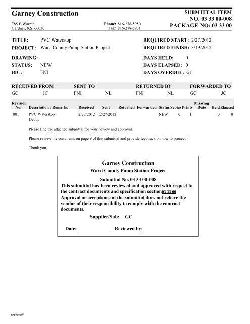
<strong>Garney</strong> <strong>Construction</strong>785 E WarrenGardner, KS 66<strong>03</strong>0Phone: 816-278-5950Fax: 816-278-5931SUBMITTAL ITEMNO. <strong>03</strong> <strong>33</strong> <strong>00</strong>-<strong>00</strong>8PACKAGE NO: <strong>03</strong> <strong>33</strong> <strong>00</strong>TITLE:PROJECT:<strong>PVC</strong> <strong>Waterstop</strong>Ward County Pump Station ProjectREQUIRED START:REQUIRED FINISH:2/27/20123/19/2012DRAWING:STATUS:BIC:NEWFNIDAYS HELD: 0DAYS ELAPSED: 0DAYS OVERDUE: -21RECEIVED FROMGC JCSENT TOFNINLRETURNED BYFNI NLFORWARDED TOGC JCRevisionNo.Description / RemarksReceivedSentDrawingReturned Forwarded Status Sepias Prints Date HeldElapsed<strong>00</strong>1 <strong>PVC</strong> <strong>Waterstop</strong> 2/27/2012 2/27/2012 NEW 0 1 0 0Debby,Please find the attached submittal for your review and approval.Please review the comments on page 9 of this submittal and provide feedback on how to proceed.Thank you,<strong>Garney</strong> <strong>Construction</strong>Ward County Pump Station ProjectSubmittal No. <strong>03</strong> <strong>33</strong> <strong>00</strong>-<strong>00</strong>8This submittal has been reviewed and approved with respect tothe contract documents and specification section<strong>03</strong> <strong>33</strong> <strong>00</strong>Approval or acceptance of the submittal does not relieve thevendor of their responsibility to comply with the contractdocuments.Supplier/Sub:GCDate: ______________ Reviewed by: _________________Expedition ®
Colorado River Municipal Water DistrictWard County Water Supply Expansion ProjectSubmittal <strong>03</strong> <strong>33</strong> <strong>00</strong> – <strong>00</strong>8-A – <strong>PVC</strong> <strong>Waterstop</strong>Table of ContentsPage 1<strong>Garney</strong> Cover LetterPage 2<strong>Garney</strong> Table of ContentsPage 3 Specification <strong>03</strong> <strong>33</strong> <strong>00</strong>Page <strong>33</strong>Greenstreak <strong>PVC</strong> <strong>Waterstop</strong> CatalogPage 45Greenstreak <strong>PVC</strong> <strong>Waterstop</strong> Installation Guide
<strong>03</strong> 30 <strong>00</strong> CAST-IN-PLACE CONCRETE1.<strong>00</strong> GENERAL1.01 SUMMARYA. Furnish labor, materials, mixing and transporting equipment and incidentals necessary toproportion, mix, transport, place, consolidate, finish and cure concrete in the structure.1.02 DEFINITIONSA. Cementitious Materials: Portland cement alone or in combination with one or more of thefollowing: blended hydraulic cement, fly ash and other pozzolans, ground granulated blastfurnaceslag, and silica fume; subject to compliance with requirements.1.<strong>03</strong> SUBMITTALSA. Submittals shall be in accordance with Section 01 <strong>33</strong> <strong>00</strong> “Submittal Procedures” and shallinclude:1. Shop Drawings:a. Mix design: For each concrete mix, complete the form “Concrete Mix Design” andone of the following forms: “Documentation of Required Average Strength – FieldStrength Test Record” or “Documentation of Average Strength – Trial Mixtures.”b. Submit a schedule to the Owner’s representative which shows the sequence ofconcrete placements.2. Certified Test Reports:a. Materials used in the trial mix design.b. Aggregate, conforming to ASTM C<strong>33</strong>, including the test reports for soundness andabrasion resistance.c. Aggregate:1). Verification that aggregate is not “potentially reactive” per ASTM C289.2). Or a cement chemical analysis indicating that the total alkali content isacceptable per Paragraph 2.02A.d. 7-day and 28-day compressive strength tests results. When more than (15) 28-daycompressive tests results are available from the current project for a given class ofconcrete, include the 15-test running average compressive strength versus therequired average compressive strength (based on the previous 15 tests) in graphicalform.3. Record Data: Manufacturer’s literature on specified materials.1.04 QUALITY ASSURANCEA. Installer Qualifications: An experienced installer who has completed concrete work similarin material, design, and extent to that indicated for this Project and whose work hasresulted in construction with a record of successful in-service performance.Cast-In-Place Concrete <strong>03</strong> 30 <strong>00</strong> - 1CMD11269 – Ward County Transmission System Expansion – Contract C6 – Below Slab TPS, OPS, and WPS
B. Manufacturer Qualifications:1. A firm experienced in manufacturing ready-mixed concrete products complying withASTM C94 requirements for production facilities and equipment.2. Manufacturer must be certified according to the National Ready Mixed ConcreteAssociation’s Certification of Ready Mixed Concrete Production Facilities.C. Testing Agency Qualifications:1. An independent testing agency, acceptable to authorities having jurisdiction and theEngineer, qualified according to ASTM C1077 and ASTM E329 to conduct the testingindicated, as documented according to ASTM E548.2. Personnel conducting field tests shall be qualified as ACI Concrete Field TestingTechnician, Grade 1, according to ACI CP-1 or an equivalent certification program.D. Source Limitations: Obtain each type or class of cementitious material of the same brandfrom the same manufacturer’s plant, each aggregate from one source, and each admixturefrom the same manufacturer.E. Pre-submittal Conference: Conduct conference at Project site to comply with requirementsin Section 01 31 <strong>00</strong> “Project Management and Coordination.”1.05 DELIVERY, STORAGE, AND HANDLINGA. Deliver cement in bulk or bags which are plainly marked with the brand and manufacturer’sname. Immediately upon receipt, store cement in a dry, weather-tight and properlyventilated structure which excludes moisture. Storage facilities shall permit easy access forinspection and identification. Cement not stored in accordance with the requirements shallnot be used.B. Sufficient cement shall be in storage to complete placement of concrete started. In orderthat cement may not become unduly aged after delivery, maintain records of delivery dates.Use cement which has been stored at the site for 60 days or more before using cement oflesser age. No cement shall be used which is lumped, caked, stored more than 90 days, orwhose temperature exceeds 170 F.C. Handle and store concrete aggregate in a manner which prevents the admixture of foreignmaterials. If the aggregates are stored on the ground, grub the sites for the stockpiles, clearweeds and grass and level. Do not disturb the bottom layer of aggregate or use without recleaning.D. Store different types and gradations of aggregates in a manner which prevents intermixing.Handle materials in stockpiles in a manner which prevents segregation of materials in thepile. Build in layers not over 3 feet in depth. Should segregation occur, remix theaggregates to conform to grading requirements. Stockpile fine aggregates at least 24 hoursbefore mixing to reduce the free moisture content.Cast-In-Place Concrete <strong>03</strong> 30 <strong>00</strong> - 2CMD11269 – Ward County Transmission System Expansion – Contract C6 – Below Slab TPS, OPS, and WPS
1.06 STANDARDSA. Mixing, sampling, placing, curing and testing of concrete, and the materials used shall be incompliance with the latest revisions of the following standards, unless otherwise noted inthe Contract Documents. The Contractor shall maintain one copy of each of the applicablestandards at the construction field office.1. American Society for Testing and Materials (ASTM) Standards:ASTM C31ASTM C<strong>33</strong>ASTM C39ASTM C42ASTM C87ASTM C94ASTM C109ASTM C125ASTM C143ASTM C150ASTM C156ASTM C171ASTM C172ASTM C173ASTM C191ASTM C192ASTM C231ASTM C260ASTM C289ASTM C293ASTM C309Standard Practice for of Making and Curing Concrete TestSpecimens in the FieldStandard Specification for Concrete AggregatesStandard Specification Test Method for Compressive Strength ofCylindrical Concrete SpecimensStandard Specification Test Method for Obtaining and TestingDrilled Cores and Sawed Beams of ConcreteStandard Specification Test Method for Effect of OrganicImpurities in Fine Aggregate on Strength of MortarStandard Specification of Ready Mixed ConcreteStandard Test Method for Compressive Strength of HydraulicCement MortarsTerminology Relating to Concrete and Concrete AggregatesStandard Test Method for Slump of Hydraulic Cement ConcreteStandard Specification for Portland CementStandard Test Method for Water Retention by Concrete CuringMaterialsStandard Specification for Sheet Materials for Curing ConcreteStandard Practice for Sampling Freshly Mixed ConcreteStandard Test Method for Air Content of Freshly Mixed Concreteby the Volumetric MethodStandard Test Method for Time of Setting of Hydraulic Cement byVicat NeedleStandard Practice for Making and Curing Concrete TestSpecimens in the LaboratoryStandard Test Method for Air Content of Freshly Mixed Concreteby the Pressure MethodStandard Specification for Air-Entraining Admixtures for ConcreteStandard Test Method for Potential Alkali-Silica Reactivity ofAggregates (Chemical Method)Standard Test Method for Flexural Strength of Concrete (UsingSimple Beam with Center-Point Loading)Standard Specification for Liquid Membrane Forming Compoundsfor Curing ConcreteCast-In-Place Concrete <strong>03</strong> 30 <strong>00</strong> - 3CMD11269 – Ward County Transmission System Expansion – Contract C6 – Below Slab TPS, OPS, and WPS
C. Fly Ash/Pozzolans: Conforming to ASTM C618, Class F fly ash; used in all classes of concrete.A supplier’s certificate of the analysis and composition of the fly ash shall be supplied.D. Coarse Aggregate:1. Crushed stone or gravel conforming to ASTM C<strong>33</strong>, in the gradation size specified.2. For gradation size number 467, a maximum aggregate size of 1-1/2 inches is:Sieve Size Percent Retained Percent Passing2” 0 1<strong>00</strong>1-1/2” 0-5 95-10<strong>03</strong>/4” 30-65 35-7<strong>03</strong>/8” 70-90 10-30No. 4 95-1<strong>00</strong> 0-53. For gradation size number 57, the maximum aggregate size of 1 inch is:Sieve Size Percent Retained Percent Passing1-1/2” 0 1<strong>00</strong>1” 0-5 95-1<strong>00</strong>1/2” 40-75 25-60No. 4 90-1<strong>00</strong> 0-10No. 8 95-1<strong>00</strong> 0-5E. Fine Aggregate:1. Washed and screened natural sands or sands manufactured by crushing stones;conforming to ASTM C<strong>33</strong>. The gradation in ASTM C<strong>33</strong> for air entrained concrete is:Sieve Size Percent Retained Percent Passing3/8” 0 1<strong>00</strong>#4 0-5 95-1<strong>00</strong>#8 0-20 80-1<strong>00</strong>#16 15-50 50-85#30 40-75 25-60#50 70-90 10-302. Fine aggregate shall have not more than 45 percent retained between any twoconsecutive sieves. Its fineness modulus, as defined in ASTM C125, shall be not lessthan 2.3 nor more than 3.1.F. Water: Potable and complying with ASTM C94.Cast-In-Place Concrete <strong>03</strong> 30 <strong>00</strong> - 6CMD11269 – Ward County Transmission System Expansion – Contract C6 – Below Slab TPS, OPS, and WPS
2.<strong>03</strong> ADMIXTURESA. Air Entraining Admixture: Conforming to ASTM C260. The total average air content shall bein accordance with recommendations of ACI 211.1; 4.5 percent plus or minus 1.5 percent for1-1/2-inch maximum size aggregate.B. Water Reducing Admixtures: Conforming to ASTM C494; Types “A” or “D” only; accuratelymeasured and added to the mix according to the manufacturer’s recommendations.C. Set Retarding Admixtures: Conforming to ASTM C494; Types “B” and “D” only; accuratelymeasured and added to the mix in according to the manufacturer’s recommendations.D. Water Reducing Admixtures - High Range (HRWR): High Range Water Reducer shall complywith ASTM C494, Type F or G. HRWR shall be accurately measured in accordance with themanufacturer’s recommendations. HRWR shall be added to the concrete mix at theconcrete batch plant. HRWR may not be added at placement site except to redose a batchand only after approval of the HRWR manufacturer. The high range water reducingadmixture shall be able to maintain the plasticity range without significant loss of slump orrise in concrete temperature for 2 hours. With the use of these admixtures, slump limitshall be between 7 and 9 inches unless otherwise authorized by the manufacturer. Otheradmixtures may only be used with the HRWR if approved by the HRWR manufacturer. Arepresentative of the HRWR manufacturer shall be present during any large placement,placement of slabs, or during times of unusual circumstance which may require changes tothe product formulation.2.04 WATERSTOPS1. Manufacturers:a. Master Builders, Inc.b. W. R. Grace & Co.c. Sika Corporation.A. Flexible <strong>PVC</strong> <strong>Waterstop</strong>s: CE CRD-C 572, for embedding in concrete to prevent passage offluids through joints. Factory fabricate corners, intersections, and directional changes.Unless indicated otherwise, provide the following configurations.1. <strong>Construction</strong> Joints:a. Profile: Ribbed without center bulb.b. Width: 6 inches.c. Minimum thickness: 3/8 inch.2. Expansion Joint:a. Profile: Ribbed with center bulb.b. Width: 9 inches.c. Minimum thickness: 3/8 inch.B. Manufacturers:1. <strong>PVC</strong> <strong>Waterstop</strong>s:Cast-In-Place Concrete <strong>03</strong> 30 <strong>00</strong> - 7CMD11269 – Ward County Transmission System Expansion – Contract C6 – Below Slab TPS, OPS, and WPS
a. Greenstreak.b. Meadows: W. R. Meadows, Inc.c. Murphy: Paul Murphy Plastics Co.d. Progress Unlimited Inc.e. Sternson Group.f. Tamms Industries Co.; Div. of LaPorte <strong>Construction</strong> Chemicals North America, Inc.g. Vinylex Corporation.h. Westec Barrier Technologies; Div. of Western Textile Products, Inc.C. Self-Expanding Strip <strong>Waterstop</strong>s (Hydrophilic): Self-expanding strip waterstops shall be usedonly where specifically indicated. Manufactured rectangular or trapezoidal strip, sodiumbentonite or other hydrophylic material for adhesive bonding to concrete.1. Products:a. Adeka Ultra Seal; Mitsubishi International Corporation.2.05 FLOOR AND SLAB TREATMENTSA. Floor Hardener: Hardening agent for exposed concrete floors shall be dry-shake surfacehardener Masterplate 2<strong>00</strong> by Master Builders, Inc. The standard application rate for thisproduct shall be in accordance with the manufacturer’s recommendations.2.06 CURING MATERIALSA. Sheet Curing Material: Conforming to ASTM C171.1. Waterproof paper.2. Polyethylene film.3. White burlap - polyethylene film.B. Membrane Curing Compounds: Membrane curing compound conforming to ASTM C309;having a color to indicate coverage when applied; non-staining; applied according to themanufacturer’s recommendations. No curing compound shall be used on walls which are toreceive a plaster mix finish. When tested according to ASTM C156, the curing compoundshall provide a film which has retained, within the specimen, the following percentages ofmoisture present when the curing compound was applied:1. At least 97 percent at the end 24 hours.2. At least 95 percent at the end of 3 days.3. At least 91 percent at the end of 7 days.C. Concrete Curing and Sealing Compound: Where a sealer is necessary, use a concrete curingand sealing compound. Application of this product shall be in accordance with themanufacturer’s recommendations.1. Interior Concrete surfaces: Sonneborn Kure-N-Seal W, by BASF The Chemical Company.2. Outdoor Concrete Surfaces: Sonneborn Kure 1315, by BASF The Chemical Company.Cast-In-Place Concrete <strong>03</strong> 30 <strong>00</strong> - 8CMD11269 – Ward County Transmission System Expansion – Contract C6 – Below Slab TPS, OPS, and WPS
D. Finishing Aid: Spraying material designed to form a monomolecular film on fresh concretethat reduces the rate of evaporation of surface moisture prior to finishing; conforming toConfilm, as manufactured by Master Builders, Inc. This material is not a curing compound.Concrete must be cured as specified.2.07 RELATED MATERIALSA. Joint Materials for Water-Retaining Structures:1. Pre-molded, resilient, non-bituminous expansion joint filler conforming to ASTM D1752,Type “II”, in the thickness specified.2. Joint sealer conforming to ASTM D6690.3. Expansion joint sealant for non-potable water shall be a two-component, non-sag,polysulfide-base, elastomeric sealing compound. The material shall conform to FederalSpecification TT S <strong>00</strong>227E, Type “II”, Class B; installed according to the manufacturer’srecommendations. Backing material for sealant shall be a rod of a diameter andcomposition recommended by the sealant manufacturer.4. Expansion joint sealant for potable water shall be a two-component, non-sag,polysulfide sealant containing no lead or mercury; conforming to Fed. Spec. TT S<strong>00</strong>227E, Type “II”, Class A; applied according to the manufacturer’s specifications.Backing material for sealant shall be a rod of a diameter and composition recommendedby the sealant manufacturer.5. Where surface is to receive a swept in grout topping, a 3-inch wide, 1-mil polyethylenestrip shall be placed above the joint sealant and held in place with 1-inch widepolyethylene tape spaced at 12-inch centers (maximum).B. Joint Materials for Non-Water-Retaining Structures: Bituminous-type, preformed,expansion joint filler; conforming to ASTM D994.C. Bonding Agents: Install according to the manufacturer’s recommendations and writteninstructions.1. Products:a. Sika Armatec 110 EpoCem by Sika Corporation.b. Sikadur 32, Hi-Mod by Sika Corporation.D. Non-Shrink Grout:1. General: Non-shrink grout for grouting of pump, motor, and equipment baseplates orbedplates, column baseplates, other miscellaneous baseplates, piping block outs andother uses of grout. Grout shall meet the following requirements, as verified byindependent laboratory tests:a. No shrinkage from the time of placement, or expansion after set, under ASTM C827and CRD C621 83 (Corps of Engineers). When non shrink grouts are tested underCRD C621 83, the grout shall be tested in a fluid state. A fluid state shall be definedas flowing through a flow cone at a rate of 20 seconds, plus or minus 5 seconds.b. An initial set time of not less than 45 minutes under ASTM C191.Cast-In-Place Concrete <strong>03</strong> 30 <strong>00</strong> - 9CMD11269 – Ward County Transmission System Expansion – Contract C6 – Below Slab TPS, OPS, and WPS
2. Non Shrink Non Metallic Grout: Pre mixed, non-staining, non-shrink grout; minimum 28-day compressive strength of 5<strong>00</strong>0 psi.a. Do not use for vibrating equipment.b. Products:1). Masterflow 713 Plus by BASF The Chemical Company.2). Five Star Grout by Five Star Products, Inc.3). SikaGrout 212 by Sika Corporation.3. Non Shrink Epoxy Structural Grouts: Furnished in two components from the factory andmixed on the job site; conforming to ASTM C579, ASTM C580, and ASTM C827; chemicalresistant, water resistant and a minimum 7-day compressive strength of 12,<strong>00</strong>0 psi.a. Use for vibrating equipment.b. Products:1). Sikadur 42, Grout-Pak by Sika Corporation.2). Five Star HP Epoxy Grout by Five Star Products, Inc.3). Masterflow 648 CP by BASF The Chemical Company.E. Normal Shrinkage Grout: 1 part Portland cement, Type I, to 3 parts of clean, first qualitysand; proportioning on a volumetric basis; used for non-structural applications for groutingareas as shown on the plans which do not require non-shrink grout.F. Foundation Waterproofing: Thoroseal Foundation Coating as manufactured by ThoroSystems Products. Foundation coating shall be used only on the exterior of concrete wallsnot exposed to view where indicated on the drawings.G. Zinc Rich Primer: Aluminum surfaces which contact or are embedded in concrete shall becoated with zinc rich primer. Primer shall be Tneme-Zinc.2.08 REPAIR MATERIALSA. Structural Concrete Repair Material: Non-shrink, non-slump, non-metallic, quick settingpatching mortar; as approved by the manufacturer for each application and appliedaccordance with the manufacturer’s recommendations.1. Products:2.09 CONCRETE MIXTURESa. Sikatop 123 by Sika Corporation.b. Five Star Structural Concrete by Five Star Products, Inc.A. Design Criteria:1. Concrete shall be composed of Portland cement, fine aggregate, coarse aggregate,admixtures and water, as specified. All Class A and C concrete shall include high rangewater reducer (HRWR).Cast-In-Place Concrete <strong>03</strong> 30 <strong>00</strong> - 10CMD11269 – Ward County Transmission System Expansion – Contract C6 – Below Slab TPS, OPS, and WPS
2. ACI 211.1 shall be the basis for selecting the proportions for concrete made withaggregates of normal and high density and of workability suitable for usual cast in placestructures.3. The design of the concrete shall be consistent with the minimum requirements ofstrength and proportions stated herein and in accordance with ACI Standard 211.1“Standard Practice for Selecting Proportions for Normal, Heavyweight, and MassConcrete,” subject to maximum water cement ratio, minimum cement content andminimum strengths specified.4. The workability of any mix shall be as required for the specific placing conditions and themethod of placement. The concrete shall have the ability to be worked readily intocorners and around reinforcing steel without the segregation of materials or thecollection of free water on the surface. Compliance with specified slump limitationsshall not necessarily designate a satisfactory mix.5. In no case shall the amount of coarse material produce harshness in placing orhoneycombing in the structure, when forms are removed.6. The maximum amount of coarse aggregate (dry loose volume) per cubic foot of finishedconcrete shall not exceed 0.82 cubic feet.7. The maximum amount of water includes the water in the aggregate, with theaggregates in a saturated, surface-dry condition.8. The maximum water content shall be the amount added at the mixer, plus the freewater in the aggregate, and minus the absorption of the aggregate based on a 30-minute absorption period. No allowance shall be made for the evaporation of waterafter batching. If additional water is required to obtain the desired slump, acompensating amount of cement shall also be added. In no case shall the maximumwater cement ratio exceed the specified maximum or that of the approved mix design.No additional compensation shall be made for additional cement.9. If fly ash is to be used in place of cement, no more than 20 percent of the cement maybe replaced.10. Concrete of 3<strong>00</strong>0 psi or stronger shall contain air entraining admixtures with theexception of drilled shafts. However, drilled shafts shall also contain air-entrainingadmixtures if fly ash is used or if placed underwater.11. When job conditions dictate, water-reducing and set-controlling admixtures may beused. Only specified admixtures shall be used. Admixtures shall be batched at thebatch plant.12. Concrete shall be capable of developing two-thirds of the required 28-day compressivestrength in 7 days.Cast-In-Place Concrete <strong>03</strong> 30 <strong>00</strong> - 11CMD11269 – Ward County Transmission System Expansion – Contract C6 – Below Slab TPS, OPS, and WPS
B. Concrete Classifications:ClassMin. 28-DayCompressiveStrength (psi)A 4<strong>00</strong>0B 3<strong>00</strong>0C 4<strong>00</strong>0E 15<strong>00</strong>Max. SizeAggregate(inches)1.5***Size No. 4671.5Size No. 4671.0Size No. 571.5Size No. 467Max. Water:Cement RatioMax.Slump(inches)*Min. Sacks OfCement PerCubic Yard**0.45 4 5.750.47 4 5.750.45 5 6.250.70 4 4.0*Maximum slump with high range water reducing admixture may be increased to 7” - 9”.** Provide one additional sack of cement per cubic yard if concrete must be deposited inwater.*** Maximum aggregate size may be reduced to 1 inch if six sacks of cement per cu yardare used.C. Concrete Usage:Class A UseClass B UseClass C UseClass E UseAll reinforced concrete unless otherwise specifiedSidewalks, curbs, drivewaysPumped Concrete, Drilled Shafts, Thin Wall SectionsCradling, Blocking, Foundation Seal, Lean Concrete BackfillD. Required Average Compressive Strength:1. All concrete is required to have an average compressive strength greater than thespecified strength. The required average compressive strength shall be establishedaccording to the requirements of ACI 301, 4.2.3.3.2. Standard Deviation: If the production facility has records of field tests performed withinthe past 12 months and spanning a period of not less than 60 calendar days for a class ofconcrete within 1<strong>00</strong>0 psi of that specified for the work, calculate a standard deviationand establish the required average strength f cr’ in accordance with ACI 301, 4.2.3.2 and4.2.3.3.a. If field test records are not available, select the required average strengthfrom ACI 301, Table 4.2.3.3.b.E. Documentation of Required Average Compressive Strength:1. Documentation indicating the proposed concrete proportions will produce an averagecompressive strength equal to or greater than the required average compressivestrength, shall consist of field strength records or trial mixture.2. Field Strength Records: Document field strength records according to ACI 301, 4.2.3.4.aand including the following:a. Field test data shall not be older than 1 year.Cast-In-Place Concrete <strong>03</strong> 30 <strong>00</strong> - 12CMD11269 – Ward County Transmission System Expansion – Contract C6 – Below Slab TPS, OPS, and WPS
. If field test data are available and represent a single group of at least 10 consecutivestrength tests for one mixture, using the same materials, under the sameconditions, and encompassing a period of not less than 60 days, verify that theaverage of the field test results equals or exceeds f cr’ . Submit for acceptance themixture proportions along with the field test data.c. If the field test data represent two groups of compressive strength tests for twomixtures, plot the average strength of each group versus the water-cementitiousmaterials ratio of the corresponding mixture proportions and interpolate betweenthem to establish the required mixture proportions for f cr’ .3. Trial Mixtures:a. Establish trial mixture proportions according to ACI 301, 4.2.3.4.b and including thefollowing.1). Make at least three trial mixtures complying with performance and designrequirements. Each trial mixture shall have a different cementitious materialcontent. Select water-cementitious materials ratios that will produce a range ofcompressive strengths encompassing the required average compressivestrength f cr’ .2). Submit a plot of a curve showing the relationship between water-cementitiousmaterials ratio and compressive strength.3). Establish mixture proportions so that the maximum water-cementitiousmaterials ratio is not exceeded when the slump is at the maximum specified.b. Laboratory samples shall be taken in accordance with the trial mix designs forlaboratory testing purposes.c. The fresh concrete shall be tested for Slump (ASTM C143) and Air Content (ASTMC173 and ASTM C231). Strength test specimens shall be made, cured and tested for7-day and 28-day strength in accordance with ASTM C192, ASTM C39, and ASTMC293.d. Suitable facilities shall be provided for readily obtaining representative samples ofaggregate from each of the weigh batchers for test purposes and for obtainingrepresentative samples of concrete for uniformity tests. The necessary platforms,tools, and equipment for obtaining samples shall be furnished. Aggregates shall betested in accordance with ASTM C289.e. The cement contents specified are minimum values. If additional quantities arerequired to obtain the specified strengths, supply the cement at no additional costto the Owner.f. A trial mix shall be designed by an independent testing laboratory, retained and paidby the Contractor and approved by the Owner. The testing laboratory shall submitverification that the materials and proportions of the trial concrete mix design meetthe specifications.g. From these trial mix tests, the ratios between 7-day and 28-day strengths shall beestablished. The 7-day strength which corresponds to the required 28-day strengthshall be determined.Cast-In-Place Concrete <strong>03</strong> 30 <strong>00</strong> - 13CMD11269 – Ward County Transmission System Expansion – Contract C6 – Below Slab TPS, OPS, and WPS
h. The final results of the trial mix design shall be submitted to the Engineer at least 10days prior to the scheduled beginning of concrete placement and shall be approvedby the Engineer prior to the placement of any concrete.4. Revisions to concrete mixtures:2.10 OFF SITE BATCH PLANTa. When less than 15 compressive strength tests results for a given class of concreteare available from the current project:1). If any of the If any of the following criteria are met, take immediate steps toincrease average compressive strength of the concrete.a). A 7-day compressive strength test result multiplied by 1.5 falls below therequired 28-day compressive strength.b). A 28-day compressive strength tests result is deemed not satisfactory.b. When at least 15 compressive strength test results for a given class of concretebecome available from the current project:1). Calculate the actual average compressive strength, standard deviation andrequired average compressive strength using the previous 15 consecutivestrength tests. Submit results in graphical form with each 28-day test result forthat class of concrete.2). If any of the following criteria are met, take immediate steps to increaseaverage compressive strength of the concrete.a). A 7-day compressive strength test result multiplied by the average job-todateratio of 7-day to 28-day compressive strength falls below the required28-day compressive strength.b). A 28-day compressive strength tests result is deemed not satisfactory.c). The average compressive strength falls below the required averagecompressive strength.c. When revisions to the mix design are required, notify the Engineer in writing of thecorrective actions taken.A. Batch plants shall be an established concrete batching facility meeting the requirements ofthe Concrete Plant Standards of the Concrete Plant Manufacturers Bureau.2.11 CONCRETE MIXINGA. Mixers may be stationary, truck, or paving mixers of approved design. They shall be capableof combining the materials into a uniform mixture and of discharging without mixturesegregation. Stationary and paving mixers shall be provided with an acceptable device tolock the discharge mechanism until the required mixing time has elapsed. The mixers ormixing plant shall include a device for automatically counting the total number of batches ofconcrete mixed. The mixers shall be operated at the drum or mixing blade speed designatedby the manufacturer on the name plate.Cast-In-Place Concrete <strong>03</strong> 30 <strong>00</strong> - 14CMD11269 – Ward County Transmission System Expansion – Contract C6 – Below Slab TPS, OPS, and WPS
B. The mixing time for stationary mixers shall be based upon the mixer’s ability to produceuniform concrete throughout the batch and from batch to batch. For guidance purposes,the manufacturer’s recommendations, or 1 minute for 1 cubic yard plus 1/4 minute for eachadditional cubic yard may be used. Final mixing time shall be based on mixer performance.Mixers shall not be charged in excess of the capacity specified by the manufacturer.C. When a stationary mixer is used for partial mixing of the concrete (shrink mixed), thestationary mixing time may be reduced to the minimum necessary to intermingle theingredients (about 30 seconds).D. When a truck mixer is used, either for complete mixing (transit-mixed) or to finish the partialmixing in a stationary mixer and in the absence of uniformity test data, each batch ofconcrete shall be mixed not less than 70 nor more than 1<strong>00</strong> revolutions of the drum, at therate of rotation designated by the manufacturer of the equipment as mixing speed. If thebatch is at least 1/2 cubic yard less than the rated capacity, in the absence of uniformity testdata, the number of revolutions at mixing speed may be reduced to no less than 50.Additional mixing shall be performed at the speed designated by the manufacturer of theequipment as agitating speed. When necessary for proper control of the concrete, mixing oftransit-mixed concrete shall not be permitted until the truck mixer is at the site of theconcrete placement. Truck mixers shall be equipped with accurate revolution counters.E. Paving mixers may be either single compartment drum or multiple compartment drum type.A sled or box of suitable size shall be attached to the mixer under the bucket to catch anyconcrete spillage that may occur when the mixer is discharging concrete into the bucket.Multiple compartment drum paving mixers shall be properly synchronized. The mixing timeshall be determined by time required to transfer the concrete between compartments ofthe drum.F. Vehicles used in transporting materials from the batching plant to the paving mixers shallhave bodies or compartments of adequate capacity to carry the materials and to delivereach batch, separated and intact, to the mixer. Cement shall be transported from thebatching plant to the mixers in separate compartments which are equipped with windproofand rain proof covers.3.<strong>00</strong> EXECUTION3.01 PREPARATIONA. Notify the Owner’s representative upon completion of various portions of the work requiredfor placing concrete, so that inspection may be made as early as possible. Keep the Owner’srepresentative informed of the anticipated concrete placing schedules.B. All items, including lines and grades, forms, waterstops, reinforcing, inserts, piping,electrical, plumbing and the Contractor’s concreting materials and equipment shall be incompliance with the plans and specifications before proceeding.C. Do not place any concrete until formwork and the placing reinforcement in that unit iscomplete. Place no concrete before the completion of all adjacent operations which mightprove detrimental to the concrete.Cast-In-Place Concrete <strong>03</strong> 30 <strong>00</strong> - 15CMD11269 – Ward County Transmission System Expansion – Contract C6 – Below Slab TPS, OPS, and WPS
D. Brilliantly light the work site so that all operations are plainly visible when concrete mixing,placing, and finishing, continues after daylight. Whenever possible, concrete finishing shallbe completed in daylight hours.E. When placing concrete, the forms shall be clean and entirely free from all chips, dirt,sawdust and other extraneous matter. Forms for slab, beam and girder construction shallnot have tie wire cuttings, nails, or any other matter which would mar the appearance ofthe finished construction. Clean forms and keep them free of any foreign matter duringconcrete placing.F. The concrete shall be mixed in quantities required for immediate use. Any concrete which isnot in place within the time limits specified shall not be used. Concrete shall not be retempered.G. Concrete shall not be placed if impending weather conditions would impair the quality ofthe finished work.H. Unless otherwise provided, the following requirements shall govern the time sequence onwhich construction operations shall be carried.1. Forms for walls or columns shall not be erected on concrete footings until the concretein the footing has cured for at least 2 curing days. Concrete may be placed in a wall orcolumn as soon as the forms and reinforcing steel placements are approved.2. Steel beams or forms and falsework for superstructures shall not be erected on concretesubstructures until the substructure concrete has cured for at least 4 curing days.Falsework required for superstructures shall not be erected until the substructure hascured for 4 curing days, and shall not be removed until the superstructure has cured.3.02 EMBEDDED ITEMS3.<strong>03</strong> JOINTSA. Where aluminum anchors, aluminum shapes, or aluminum electrical conduits areembedded in concrete, paint aluminum contact surfaces with zinc rich primer. Allow thepaint to thoroughly dry before placing the aluminum in contact with the concrete.B. Paint steel or other ferrous metal to be mounted on or placed in contact with dry/curedconcrete, and coat in accordance with Section 09 96 <strong>00</strong>.01 “High-Performance Coatings”prior to installation.A. Expansion Joints and Devices:1. Workmanship: Exercise careful workmanship in joint construction to separate theconcrete sections by an open joint or by the joint materials, and make the joints true tothe outline indicated.2. Expansion Joints: Construct expansion joints and devices to provide expansion andcontraction. Construct joints which are to be left open or filled with poured jointmaterial with forms which are adaptable for loosening or early removal. In order toavoid jamming by the expansion action of the concrete and the consequent likelihood ofinjuring adjacent concrete, remove or loosen these forms as soon as possible after theconcrete has initially set. Make provisions for loosening the forms to permit freeconcrete expansion without requiring full removal.Cast-In-Place Concrete <strong>03</strong> 30 <strong>00</strong> - 16CMD11269 – Ward County Transmission System Expansion – Contract C6 – Below Slab TPS, OPS, and WPS
3. Armored Joints: Carefully construct armored joints to avoid defective anchorage of thesteel and porous or honeycombed concrete adjacent to same. Anchor pre-moldedmaterials to the concrete on one side of the joint with approved adhesive. Anchor sothat the material does not fall out of the joint.B. <strong>Construction</strong> Joints:1. <strong>Construction</strong> joints are formed by placing plastic concrete in direct contact withconcrete which has attained its initial set. When concrete is specified as monolithic, theterm shall be interpreted as the manner and sequence of concrete placement so thatconstruction joints do not occur.a. Unless noted otherwise, the maximum horizontal spacing of construction joints shallbe 40 feet.b. For slabs on grade, the maximum spacing between two construction joints orbetween a construction joint and a control joint shall be 15 feet, unless notedotherwise.c. Unless noted otherwise or approved by the Engineer, the maximum vertical spacingof construction joints shall be 15 feet. If not detailed on the drawings, constructionjoint details and locations shall be submitted to the Engineer for approval.2. Additional horizontal and vertical construction joints, when submitted and approved bythe Engineer, may have an impact on reinforcing details. Revise reinforcing details toreflect additional joints.3. Unless otherwise provided, construction joints shall be square and normal to the forms.Provide bulkheads in the forms for all joints except horizontal joints.4. At the proper time, clean horizontal construction joints for receiving the succeeding liftusing air water cutting. The surface shall be exposed sound, clean aggregate. The airpressure supply to the jet shall be approximately 1<strong>00</strong> lb. per square inch, and the waterpressure sufficient to bring the water into effective influence of the air pressure. Aftercutting, wash the surface until there is no trace of cloudiness in the wash water.5. In areas where air water cutting cannot be satisfactorily accomplished, or in areas whereit is undesirable to disturb the surface of the concrete before it has hardened, preparethe surface for receiving the next lift by wet sand blasting to immediately remove alllaitance and unsound concrete prior to placing of the next lift. Thoroughly wash thesurface of the concrete after sand blasting to remove all loose material.6. Provide construction joints with concrete keyways, reinforcing steel dowels, andwaterstops. The method of forming keys in keyed joints shall permit the easy removalof forms without chipping, breaking, or damaging the concrete.C. Control Joints in Slabs-on-Grade: Form weakened-plane control joints, sectioningconcrete into areas as indicated, or at 15 feet maximum spacing. Construct control jointsfor a depth equal to at least one-fourth of concrete thickness.1. Grooved Joints: form control joints after initial floating by grooving and finishing eachedge of joint to a radius of 1/8-inch. Repeat grooving of control joints after applyingsurface finishes. Eliminate groover tool marks on concrete surfaces.2Cast-In-Place Concrete <strong>03</strong> 30 <strong>00</strong> - 17CMD11269 – Ward County Transmission System Expansion – Contract C6 – Below Slab TPS, OPS, and WPS
2. Sawed joints: form control joints with early entry dry-cut power saws within 2 hoursof finishing operations. Cut 1/8-inch wide joints for unsealed joints or 1/2- inch widejoints for sealed joints into concrete when cutting action will not tear, abrade, orotherwise damage surface and before concrete develops random control cracks.D. Existing Hardened Concrete: Where new concrete or grout is to be placed in contact withexisting hardened concrete, texture the existing surface by chipping or other means so thatan irregular surface having a height variance of not less than 1/4 inch is created. Theexisting concrete shall then be coated with a bonding agent and new concrete or groutplaced.3.04 WATERSTOPSA. <strong>PVC</strong> <strong>Waterstop</strong>s: Install in construction joints as indicated to form a continuous diaphragm.Install in longest lengths practicable. Support and protect exposed waterstops duringprogress of Work.1. At formed surfaces, a split form shall be used. The split form shall have a tight fit whichprevents misalignment and concrete leakage.2. The embedded flange of the waterstop must be secured prior to concrete placement.The flange shall be secured at 12 inches on-center by factory installed hog rings orgrommets at the outermost rib. Never place nails or screws through the body of thewaterstop.3. All fittings and changes in direction shall be factory fabricated. Only straight butt splicesshall be made in the field. Field splices shall be according to the manufacturer’s writteninstructions and as follows:a. Cut adjoining ends square to form matching edges.b. Uniformly melt the ends at 380 F using a thermostatically controlled, Teflon coatedsplicing iron.c. When a 1/8-inch diameter melt bead develops on each waterstop end, remove thesplicing iron and firmly press the two ends together in proper alignment. Hold untilthe material has fused and cooled. Allow the splice to cool naturally; do notquench.B. Self-Expanding Strip <strong>Waterstop</strong>s:1. Install in construction joints and at other locations indicated, according tomanufacturer’s written instructions, bonding or mechanically fastening and firmlypressing into place.a. <strong>Waterstop</strong> shall be bonded to the substrate using a continuous bead of ADEKA UltraSeal P-201.2. Install in longest lengths practicable.3.05 CONCRETE PLACEMENTA. Cold Weather:Cast-In-Place Concrete <strong>03</strong> 30 <strong>00</strong> - 18CMD11269 – Ward County Transmission System Expansion – Contract C6 – Below Slab TPS, OPS, and WPS
1. If air temperature is at or below 40 F, cold weather concreting shall be performed inaccordance with ACI 306R.2. No concrete shall be mixed or placed when the atmospheric temperature is at or below35 F. The temperature shall be taken in the shade away from artificial heat.3. In cases where the temperature drops below 40 F after the concreting operations havebeen started, sufficient canvas and framework or other type of housing shall befurnished to enclose and protect the structure, in accordance with the requirements ofACI 306R. Sufficient heating apparatus such as stoves, salamanders, or steamequipment and fuel to provide heat shall be supplied. The concrete shall be protectedwhen placed under all weather conditions. Should concrete placed under suchconditions prove unsatisfactory, remove and replace the concrete at no cost to theOwner.4. When mixing with the air temperature below 40 F, water used for mixing shall beheated to raise the concrete temperature to 70 F. The temperature of the mixing watershall not exceed 165 F when entering the mixer.5. If heating the mixing water only does not raise the placing temperature of the concreteto 70 F, the aggregate must also be heated, either by steam or dry heat, to raise theplacing temperature of the concrete to the required temperature. In no case shall theaggregate temperature exceed 150 F as it enters the mixer. The heating apparatus shallheat the mass of the aggregate uniformly and preclude the occurrence of hot spotswhich burn the material.6. Salts, chemicals, or other foreign materials shall not be mixed with the concrete topreventing freezing. Calcium chloride is not permitted.B. Hot Weather:1. Hot weather is defined as any combination of high air temperature, low relativehumidity and wind velocity that impairs the quality of the concrete. Hot weatherconcreting shall be in accordance with ACI 305R. Concrete shall be placed in the formswithout the addition of any more water than that required by the design (slump). Noexcess water shall be added on the concrete surface for finishing. Control of initial setof the concrete and extending the time for finishing operations may be accomplishedwith the use of approved water reducing and set retarding admixture, as specified.2. Maximum time intervals between the addition of mixing water and/or cement to thebatch, and the placing of concrete in the forms shall not exceed the following (excludingHRWR admixture use):Concrete TemperatureNon-Agitated ConcreteUp to 80 FOver 80 FAgitated ConcreteUp to 75 FMaximum Time From WaterBatch to Placement30 Minutes15 Minutes90 MinutesCast-In-Place Concrete <strong>03</strong> 30 <strong>00</strong> - 19CMD11269 – Ward County Transmission System Expansion – Contract C6 – Below Slab TPS, OPS, and WPS
75 F to 89 F 60 Minutesa. The use of an approved set-retarding admixture will permit the extension of theabove time maximums by 30 minutes, for agitated concrete only.b. The use of an approved high range water reducing (HRWR) admixture will allowplacement time extensions as determined by the manufacturer.3. The maximum temperature of concrete shall not exceed 90 F at the time the concrete isplaced. The temperatures of the mixing water shall be reduced by the use of chilledwater or ice.4. The maximum temperature of concrete with high range water reducing admixture shallnot exceed 1<strong>00</strong> F at the time concrete is placed.5. Under extreme heat, wind, or humidity conditions, concreting operations may besuspended if the quality of the concrete being placed is not acceptable.C. Handling and Transporting:1. Delivery tickets shall be required for each batch and shall be in accordance with ASTMC94, Section 16. Each delivery ticket must show plainly the amount of water, in gallonsthat can be added to the mixer truck at the site without exceeding the maximum watercement ratio approved for that mix design. Amount of water added must be inproportion to contents of truck.2. Arrange and use chutes, troughs, or pipes as aids in placing concrete so that theingredients of the concrete are not segregated. They shall be steel or steel lined. Whensteep slopes are necessary, equip the chutes with baffles or make in short lengths thatreverse the direction of movement. Extend open troughs and chutes, if necessary,inside the forms or through holes left in the forms. Terminate the ends of these chutesin vertical downspouts.3. Keep chutes, troughs and pipes clean and free from coatings of hardened concrete bythoroughly flushing with water before and after placement. Discharge water used forflushing away from the concrete in place.4. Concrete pumping is permitted and shall comply with ACI 304.2R.5. Carting or wheeling concrete batches on completed concrete floor slab shall not bepermitted until the slab has aged at least 4 curing days. Unless pneumatic tired cartsare used, wheel the carts on timber planking so that the loads and impact aredistributed over the slab. Curing operations shall not be interrupted for the purpose ofwheeling concrete over finished slabs.D. Depositing:1. The method and manner of placing shall prevent segregation or separation of theaggregate or the displacement of the reinforcement. Use drop chutes of rubber ormetal when necessary. Prevent the spattering of forms or reinforcement bars if thespattered concrete dries or hardens before it is incorporated into the mass.2. Fill each part of the forms by directly depositing concrete as near its final position aspossible. Work the coarse aggregate back from the face and force the concrete underand around the reinforcement bars without displacing them. Depositing large quantitiesCast-In-Place Concrete <strong>03</strong> 30 <strong>00</strong> - 20CMD11269 – Ward County Transmission System Expansion – Contract C6 – Below Slab TPS, OPS, and WPS
5. Provide one vibrator (powered pneumatically or electrically) for each 10 cubic yards ofconcrete per hour being placed. Provide at least one vibrator, which may be of thegasoline powered type, as a standby for each two vibrators in service. To producesatisfactory consolidation, and based upon the observed performance, the Owner’srepresentative may require the use of a larger sized and powered vibrator.6. Check vibrators intended for regular service or standby service before beginningconcreting operations.F. Placement in Water:1. Deposit concrete in water only when dry conditions cannot be obtained. The forms,cofferdams, or caissons shall be sufficiently tight to prevent any water flowing throughthe space where concrete is to be deposited. Pumping of water shall not be permittedwhile the concrete is being placed, nor until it has set for at least 36 hours.2. Carefully place the concrete compact mass using a tremie, closed bottom dumpingbucket, or another approved method which does not permit the concrete to fall throughthe water without protection. The concrete shall not be disturbed after beingdeposited. Regulate depositing to maintain horizontal surfaces.3. When a tremie is used, it shall consist of a tube constructed in sections having watertightconnections. The means of supporting the tremie shall permit the movement ofthe discharge end over the entire top surface of the work, and shall allow the tremie tobe rapidly lowered to retard the flow. The number of times it is necessary to shift thelocation of the tremie shall be held to a minimum for any continuous placement ofconcrete. During the placing of concrete, keep the tremie tube full to the bottom of thehopper. When a batch is dumped into the hopper, slightly raise the tremie, but not outof the concrete at the bottom, until the batch discharges to the level of the bottom ofthe hopper. Stop the flow by lowering the tremie. Continue placing operations until thework is completed.4. When concrete is placed by means of the bottom dump bucket, the bucket shall have acapacity of not less than 1/2 cubic yard. Lower the bucket gradually and carefully until itrests upon the concrete already placed. Raise it very slowly during the discharge travelto maintain still water at the point of discharge and to avoid agitating the mixture.5. Use a sump or other approved method to channel displaced fluid and concrete awayfrom the shaft excavation. Recover slurry and dispose of it as approved. Do notdischarge displaced fluids into or in close proximity to streams or other bodies of water.G. Placement in Slabs:1. Allow concrete in columns, walls and deep beams or girders to stand for at least 1 hourto permit full settlement from consolidation, before concrete is placed for slabs they areto support. Haunches are considered as part of the slab and shall be placed integrallywith them.2. When monolithic slabs are placed in strips, the widths of the strips, unless otherwisespecified or indicated, shall insure that concrete in any one strip is not allowed to lie inplace for more than 1 hour before the adjacent strips are placed.3. Immediately before placing concrete, thoroughly dampen the earthen cushion toreceive concrete to prevent moisture absorption from the concrete.Cast-In-Place Concrete <strong>03</strong> 30 <strong>00</strong> - 22CMD11269 – Ward County Transmission System Expansion – Contract C6 – Below Slab TPS, OPS, and WPS
4. As soon as concrete placing is complete for a slab section of sufficient width to permitfinishing operations, level the concrete, strike off, tamp and screed. The screed shall beof a design adaptable to the use intended, shall have provision for vertical adjustmentand shall be sufficiently rigid to hold true to shape during use.5. The initial strike off shall leave the concrete surface at an elevation slightly above gradeso that, when consolidation and finishing operations are completed, the surface of theslab is at grade elevation.6. Continue tamping and screeding operations until the concrete is properly consolidatedand free of surface voids. Bring the surface to a smooth, true alignment usinglongitudinal screeding, floating, belting, and/or other methods.7. When used, templates shall be of a design which permits early removal so satisfactoryfinishing at and adjacent to the template is achieved.8. While the concrete is still plastic, straightedge the surface using a standard 10-footmetal straightedge. Lap each straightedge pass one-half of the preceding pass. Removehigh spots and fill depressions with fresh concrete and re-float. Continue to check witha straightedge during the final finishing operation, until the surface is true to grade andfree of depressions, high spots, voids, or rough spots.9. Check the final surface with a straightedge. Ordinates measured from the face of thestraightedge to the surface of the slab shall not exceed 1/16 inch per foot from thenearest point of contact. The maximum ordinate shall be 1/8 inch per 10 feet.10. Unless noted otherwise, where floor drains are shown in slabs of structures and slopingthe slab is not indicated, slope slab to drain on a grade of 1/16 inch per foot with amaximum total slope of 1-1/4 inches. The thickness of slab at floor drain shall be thethickness of slab, as indicated on the plans.H. Placement in Foundations: Place concrete in deep foundations so that segregation of theaggregates or displacement of the reinforcement is avoided. Provide suitable chutes orvertical pipes. When footings can be placed in dry foundation pits without the use ofcofferdams or caissons, forms may be omitted and the entire excavation filled with concreteto the elevation of the top of footing. The placing of concrete bases above seal courses ispermitted after the forms are free from water and the seal course cleaned. Executenecessary pumping or bailing during concreting from a suitable sump located outside theforms.3.06 FINISHING FORMED SURFACESA. Forms for walls, columns and sides of beams and girders shall be removed as specified inSection <strong>03</strong> 11 <strong>00</strong> “Concrete Forming.” Patch, repair, finish and clean concrete after formremoval. Finish concrete within 7 days of form removal. Cure concrete as finishingprogresses.B. Air voids, for all types of finishes, are defects and shall be removed by rubbing or patching.C. Finish Schedule:Type of FinishLocationCast-In-Place Concrete <strong>03</strong> 30 <strong>00</strong> - 23CMD11269 – Ward County Transmission System Expansion – Contract C6 – Below Slab TPS, OPS, and WPS
No FinishSmooth FinishSurfaces which are not visible from the inside or outside of thecompleted structure or more than 12 inches below finish grade(i.e. back of retaining walls below embankment, etc.)Surfaces exposed to view and areas below to a point 12 inchesbelow gradeD. No Finish: After forms are removed, repair or patch tie holes and defects. Otherwise, noadditional finish is required.E. Smooth Finish: Unless otherwise shown on the schedule above, provide smooth form finishfor concrete surfaces to be exposed to view. Surfaces to receive a rubbed finish shall have asmooth form finish. The form facing material shall produce a smooth, hard, uniform textureon the concrete. The arrangement of the facing material shall be orderly and symmetricalwith a minimum number of seams. Patch tie holes and defects and remove fins flush withthe adjacent surface.3.07 FINISHING FLOORS AND SLABSA. General: Comply with recommendations in ACI 302.1R for screeding, restraightening, andfinishing operations for concrete surfaces. Do not wet concrete surfaces.B. Finish slabs, platforms and steps monolithically and apply as indicated on the drawings andthe following schedule of finishes:Type of FinishRough FinishTrowel finishBroom FinishFloor HardenerFinishLocationTank floors that receive grout topping and slabs which receiveadditional concrete toppings.Slab surfaces exposed to view or to be covered with resilient flooring,carpet, ceramic or quarry tile set over a cleavage membrane, paint,or another thin film-finish coating system.Exterior concrete platforms, steps, and ramps.Pump room and electrical room floor slabs1. Rough Finish: Provide a rough surface by screeding only without further finish.2. Trowel Finish:a. After applying float finish, apply first trowel finish and consolidate concrete by handor power-driven trowel. Continue troweling passes and re-straighten until surface isfree of trowel marks and uniform in texture and appearance. Grind smooth anysurface defects that would telegraph through applied coatings or floor coverings.b. Finish and measure surface so gap at any point between concrete surface and anunleveled freestanding 10-foot long straightedge, resting on two high spots andplaced anywhere on the surface, does not exceed 1/8 inch.3. Broom Finish: Immediately after float finishing, slightly roughen trafficked surface bybrooming with fiber-bristle broom perpendicular to main traffic route. Coordinaterequired final finish with Architect before application.Cast-In-Place Concrete <strong>03</strong> 30 <strong>00</strong> - 24CMD11269 – Ward County Transmission System Expansion – Contract C6 – Below Slab TPS, OPS, and WPS
C. Give sidewalks a brush finish, unless noted otherwise. Score sidewalks at a spacing equal tothe width of the walk and edge on each side using a tool with a radius of approximately 1/4inch.D. Floor Hardener:1. Areas and application rates for the floor hardener shall be as indicated on the plans.2. Contractor must obtain field technical assistance from the floor hardener manufacturerto insure the installation complies with the manufacturer’s recommendations andprocedures. Sufficient notice must be given to the manufacturer’s representative for thesite visit.3. Installation, finishing and curing of the concrete after the application of the floorhardener shall be in accordance with the manufacturer’s recommendations.E. Finishing in Hot, Dry Weather: During periods of high temperature and/or low humidity,take extreme care in finishing the slabs to eliminate initial shrinkage cracks. Following theinitial set of concrete, but while the concrete is still “green” continue to finish as required toremove shrinkage cracks which may occur. In hot, dry weather, keep a cement finisher onthe job following normal finishing operations for a sufficient length of time to insure theremoval of initial shrinkage cracks.3.08 MISCELLANEOUS CONCRETE ITEMSA. Normal Shrinkage Grouting:1. Prior to grout application, thoroughly clean the surface of all foreign matter and wetdown. Thoroughly clean the foundation and the forms set in place and securely anchor,with holes or cracks in forms caulked with rags, cotton waste or dry sand mixture toprevent the loss of grout. The necessary materials and tools shall be on hand beforestarting grouting operations. Concrete shall be damp when the grout is poured, butshall not have excess water to dilute the grout.2. After wetting and just prior to grouting, sprinkle the surface lightly with cement toimprove the bond between the grout and the surface.3. After mixing, quickly and continuously place the grout to avoid overworking, segregationand breaking down of the initial set. Mix and place the grout according to themanufacturer’s recommendations. Cure grout using wet curing method for concrete.Grout shall receive a steel trowel finish.B. Non-Shrink Grout:1. Obtain field technical assistance from the Grout manufacturer, as required, to insurethat grout mixing and installation comply with the manufacturer’s recommendationsand procedures.2. Saturate the foundation for non-shrink grouts 24 hours before installation and clear ofexcess water. Free baseplates or bedplates of oil, grease, laitance and other foreignsubstances.3. Place grout according to the manufacturer’s directions so that spaces and cavities belowthe top of the baseplates and bedplates are completely filled. Provide forms wherestructural components of the baseplates or bedplates do not confine the grout. WhereCast-In-Place Concrete <strong>03</strong> 30 <strong>00</strong> - 25CMD11269 – Ward County Transmission System Expansion – Contract C6 – Below Slab TPS, OPS, and WPS
necessary and acceptable under the manufacturer’s procedures, a round head pencilvibrator, 3/4-inch maximum diameter may be used to consolidate the grout.4. Steel trowel finish the non-shrink grout where the edge of the grout is exposed to viewand after the grout has reached its initial set. Cut off the exposed edges of the grout ata 45 degree angle to the baseplate, bedplate, member, or piece of equipment.5. Wet curing should occur for at least 3 days, unless specified by manufacturer, with wetrags, wet burlap or polyethylene sheets. Keep cloths constantly wet for the curing cycle.6. Clean and dry the foundation, baseplate or other surface of epoxy grouts prior toinstallation. Dry curing is acceptable for epoxy grouts.7. Use epoxy non-shrink grout under all machinery, pumps, equipment, and wherechemicals are present that would abate cementitious non-shrink grouts.8. Mix, install, cure, and finish epoxy grouts according to the manufacturer’srecommendations. Install grout in recommended lifts to prevent excess heat.3.09 CONCRETE PROTECTION AND CURINGA. General: Give careful attention to proper concrete curing. The curing methods shall be wetcuring, sheet materials conforming to ASTM C171, or membrane curing compoundconforming to ASTM C309. Membrane curing is not permitted on surfaces to be rubbed oron surfaces to which additional concrete, plaster mix mortar or terrazzo is to be applied.Unless the curing method is specified otherwise, select the appropriate curing method.B. Length of Curing Period:1. A “curing day” shall be any day on which the atmospheric temperature taken in theshade, or the air temperature adjacent to the concrete, remains above 50 F for at least18 hours.2. Cure concrete for a period of 7 consecutive days. In cold weather, when curing may beretarded, extend this period to 7 “curing days”, up to a limit of 14 consecutive days.C. Wet Curing:1. Immediately following the finishing operations, cover concrete slabs, including roofslabs, with wet cotton mats or with a temporary covering of canvas or burlap. Keepthoroughly wet for a period of 4 curing days after the concrete is placed. The coveringshall be held in direct contact with the concrete. A temporary covering shall be requiredwhen the size of slab, size of mats, or other factors dictate that the mats cannot beplaced immediately after the finishing operations without marring the finishing of theslab.2. Water used for curing shall be free from injurious amounts of oil, acid, alkali, salt, orother deleterious substances.3. Canvas or burlap covering material shall weigh not less than 12 ounces per square yard.Place the sections with a lap at the edges of at least 8 inches. Saturate cover materialwith water previous to placing. Keep saturated as long as it remains in place. Use carein the placing of the cover material to prevent marring the concrete surface.Cast-In-Place Concrete <strong>03</strong> 30 <strong>00</strong> - 26CMD11269 – Ward County Transmission System Expansion – Contract C6 – Below Slab TPS, OPS, and WPS
4. When temporary coverings are used, keep them in place only until the slab hassufficiently hardened so that a cotton mat covering can be substituted without marringor disturbing the slab finish. Thoroughly saturate cotton mats before placing and keepthe mats on the slab in a saturated condition for a period of at least 4 curing days.D. Sheet Curing: Sheet materials shall conform to ASTM C171. They shall be in contact withthe entire concrete surface and applied according to the manufacturer’s recommendations.Patch all holes. Where pedestrian traffic is unavoidable, provide suitable walkways toprotect the sheet material.E. Membrane Curing:1. Membrane curing shall not be used on surfaces which receive paint, floor hardener, orplaster mix finish or other finish which would be hindered by the use of the curingcompound.2. Cover the surface of the concrete with a continuous, uniform, water-impermeablecoating, conforming to ASTM C309 “Liquid Membrane Forming Compounds for CuringConcrete” and apply according to ACI 308.3. Immediately after the removal of the side and end forms, apply a coating to the sidesand ends of all concrete. Apply the solution under pressure with a spray nozzle so thatthe entire exposed surface is completely covered with a uniform film. The rate ofapplication shall insure complete coverage, but the area covered shall not exceed 150square feet per gallon of curing compound.4. The coating shall be sufficiently transparent and free of permanent color to not result ina pronounced color change from that of the natural concrete at the conclusion of thecuring period. The coating shall, however, contain a dye of color strength to render thefilm distinctively visible on the concrete for a period of at least 4 hours after application.5. After application and under normal conditions, the curing compound shall be dry totouch within 1 hour and shall dry thoroughly and completely within 4 hours. Whenthoroughly dry, it shall provide a continuous flexible membrane free from cracks orpinholes and shall not disintegrate, check, peel, or crack during the required curingperiod.6. If the seal is broken during the curing period, immediately repair it with additionalsealing solution.3.10 CONCRETE SURFACE REPAIRSA. After the tie rods are broken back or removed, thoroughly clean the holes to remove greaseand loose particles. Patch holes with structural concrete repair material. After the holes arecompletely filled, strike off flush excess mortar and finish the surface to render the filledhole inconspicuous.B. If the surface of the concrete is bulged, uneven, or shows honeycombing or form marks,which in the Engineer’s opinion cannot be repaired satisfactorily, remove and replace theentire section.C. Patch honeycomb and minor defects in all concrete surfaces with structural concrete repairmaterial. Cut back each defective area with a pneumatic chipping tool as deep as the defectextends, but in no case less than 1/2 inch. Prepare the existing concrete according to theCast-In-Place Concrete <strong>03</strong> 30 <strong>00</strong> - 27CMD11269 – Ward County Transmission System Expansion – Contract C6 – Below Slab TPS, OPS, and WPS
ecommendations of patching material manufacturer’s. Apply repair material according tothe manufacturer’s recommendations. Finish the surface of the patches to match finish onsurrounding concrete.3.11 FIELD QUALITY CONTROLA. Testing:1. General:a. Tests shall be required throughout the work to monitor the quality of concrete.Samples shall be taken in accordance with ASTM C172.b. The Engineer may waive these requirements on concrete placements of ten cubicyards or less. However, evidence shall be furnished showing a design mix whichmeets the specifications.c. Unless noted otherwise, testing of the materials, ready mix, transit mix or centralplant concrete will be by an independent testing agency. The Owner will select andpay for this service. A summary of all tests performed will be available. No concreteshall be placed without a representative present at either the plant or at the projectsite.d. Unless the Owner’s laboratory is on the site, provide housing for the curing andstorage of test specimens and equipment.2. Slump Test: Slump tests, in accordance with ASTM C143, shall be used to indicate theworkability and consistency of the concrete mix from batch to batch. Generally, a slumptest shall be made at the start of operations each day, at regular intervals throughout aworking day, and at any time when the appearance of the concrete suggests a change inuniformity.3. Air Content Test: Tests for the concrete’s air content shall be made in accordance withASTM C231 or ASTM C173, at the point of delivery of concrete, prior to placing in forms.The test shall be made frequently to monitor a proper air content uniform from batch tobatch.4. Temperature Test: The temperature of the concrete to be placed shall be taken with athermometer immediately before placement, with the point of measurement being inthe chute or bucket. Temperature test shall be performed for each truck. Recordtemperatures on batch ticket.5. Compression Test:a. Compression test specimens shall be 6-by-12-inch concrete cylinders made andcured in accordance with ASTM C31. If the maximum aggregate size is no longerthan 1 inch, 4-by-8-inch concrete cylinders are acceptable. No fewer than two 6-by-12-inch or three 4-by-8-inch specimens shall be made for each test sample. Samplesshall be taken at a minimum of every 50 cubic yards of concrete for each classplaced. At least one set of test specimens per day shall be made for each class ofconcrete used that day. Specimens shall be cured under laboratory conditionsspecified in ASTM C31. Additional concrete cylinders may be required for curing onthe job under actual job curing conditions. These samples could be required when:Cast-In-Place Concrete <strong>03</strong> 30 <strong>00</strong> - 28CMD11269 – Ward County Transmission System Expansion – Contract C6 – Below Slab TPS, OPS, and WPS
1). There is a possibility of the air temperature surrounding the concrete fallingbelow 40 F, or rising above 90 F.2). The curing procedure may need to be improved and/or lengthened.3). It is necessary to determine when the structure may be put into service.b. Compression strength tests shall be made on the laboratory-cured and job-curedconcrete cylinders at 7 and 28 days, in accordance with ASTM C39. The value ofeach test result shall be the average compressive strength of all of the cylinders inthe test sample. All cylinders within a test sample shall be taken at the same timefrom the same batch of concrete. For the 28-day cylinders, the strength level shallbe satisfactory if the averages of all sets of three consecutive strength test resultsexceed the required design compressive strength, and no individual strength testresult falls below the required compressive strength by more than 5<strong>00</strong> psi.6. Failure to Meet Requirements:a. Should the 7-day strengths shown by the test specimens fall below the requiredvalues, additional curing shall be performed on those portions of the structuresrepresented by the test specimens at the Contractor’s expense. Test cores shall beobtained and tested in accordance with ASTM Test Method for Obtaining andTesting Drilled Cores and Sawed Beams of Concrete, Designation C 42. If additionalcuring does not give the strength required, the Owner reserves the right to requirestrengthening, replacement of those substandard portions of the structure, oradditional testing, at the Contractor’s expense.b. Upon receipt of the Contractor’s written request, substandard concrete work maybe reexamined in place by nondestructive testing methods or core samples, inaccordance with ACI 301. The services of an independent testing laboratory shall beretained and all expenses paid without compensation from the Owner. Laboratoryresults shall be evaluated by the Engineer, who shall make the final decision onacceptability of the concrete in question. Core sample holes shall be repaired.B. The Owner may withhold payment for any section of concrete which does not meet therequirements of these specifications. Withheld payment shall be based upon the unit pricesestablished for concrete and reinforcing steel. Payment shall be withheld until theunacceptable concrete has been refinished, removed and replaced or otherwise broughtinto conformance with the specifications.C. <strong>PVC</strong> <strong>Waterstop</strong>s: <strong>Waterstop</strong>s shall be observed by the Owner’s representative prior toconcrete placement. Unacceptable splicing defects include:1. Misalignment of center bulb, ribs and end bulbs greater than 1/16 inch.2. Bond failure at joint deeper than 1/16 inch.3. Misalignment which reduces waterstop cross section more than 15 percent.4. Bubble or visible porosity in the weld.5. Visible signs of splice separation when a cooled splice is bent by hand at a sharp angle.6. Charred or burnt material.Cast-In-Place Concrete <strong>03</strong> 30 <strong>00</strong> - 29CMD11269 – Ward County Transmission System Expansion – Contract C6 – Below Slab TPS, OPS, and WPS
END OF SECTIONCast-In-Place Concrete <strong>03</strong> 30 <strong>00</strong> - 30CMD11269 – Ward County Transmission System Expansion – Contract C6 – Below Slab TPS, OPS, and WPS
WATERSTOPS for concreteFor 60 years, Greenstreak has beenthe leading source for joint sealingtechnologies and innovative products forconcrete. Offering a variety of solutionsacross all categories of waterstops,Greenstreak has the knowledge andtime tested products to meet the mostdemanding applications.• Water/Waste Water Treatment Plants• Lock and Dam Systems• Reservoirs and Aqueducts• Flood Walls• Retaining Walls• Foundations• Tunnels and Culverts• Bridge Abutments• Containment Structures and Tanks• Slabs-on-GroundWhen you specify Greenstreak, you arespecifying the first name in waterstopsand the trusted source for superiortechnical and customer service.GREENSTREAK 8<strong>00</strong>-325-9504
Choose The Right <strong>Waterstop</strong><strong>Waterstop</strong> Basic UseEmbedded in concrete, across and/or along thejoint, waterstops form a watertight diaphragm thatprevents the passage of liquid through the joint.Suggested <strong>Waterstop</strong> Design Checklist◄◄Verify chemical containment requirements, if any◄◄Verify hydrostatic head pressure requirements◄◄Determine joint type and joint movement requirements◄◄Specify material type for best water sealing performance◄◄Specify profile and size (by product number, if possible)◄◄Verify joinery details of dissimilar or asymmetricwaterstop profiles, if any (consider using one profilethroughout to simplify intersections)◄◄Specify factory fabrications and fittings for transitionsand intersections◄◄Specify appropriate method for securing waterstopin position (see Greenstreak CSI-formatted productspecifications for additional guidance)Selecting A <strong>Waterstop</strong> ShapePhoto courtesy of Paul C. Rizzo Associates, Inc.MOVEMENT JOINTS are typically designed to accommodate significant movement dueto drying shrinkage, temperature changes, settlement, creep, or live load deflections. Thewaterstop profile selected must have the ability to accommodate expected joint movement,typically achieved through the use of a centerbulb, tear web, or other suitable waterstopgeometry designed to accommodate joint movement. Movement joints typically includecontraction joints, expansion joints, and isolation joints. The following profiles are suitablefor Movement joints:Ribbed with Centerbulb shapes are the most versatile type ofwaterstops available. The centerbulb accommodates lateral, transverse,and shear movement. Larger centerbulbs will accommodate greater movement.Tear Web shapes accommodate large movements. When joint movementoccurs, the tear web ruptures and allows the U-bulb to deform withoutputting the material in tension.Dumbbell with Centerbulb shapes accommodate lateral, transverse, andshear movement. Larger centerbulbs will accommodate greater movement.Consider using Ribbed with Centerbulb for better sealing characteristics.Base Seal with Tear Web shapes accommodate lateral, transverse, and shearmovement. Larger centerbulbs will accommodate greater movement. Base Sealwaterstops have some limitations with transitions and intersections.2 GREENSTREAK 8<strong>00</strong>-325-9504 www.Greenstreak.com
S p e c i f y G r e e n s t r e a kNONMOVING JOINTS typically have 1<strong>00</strong>% of the bonded steel reinforcement continuous through the joint,and expose the waterstop to negligible or no movement. Flat waterstop profiles without a centerbulb or tearweb are suitable for nonmoving joints. Other waterstop materials may be considered for nonmoving joints aswell, such as strip-applied or injectable hose waterstops. Examples of waterstop profiles suitable for nonmovingjoints are as follows:Flat Ribbed shapes are preferred fornonmoving joints and provide the bestsealing characteristics.Dumbbell shapes are an alternate profile fornonmoving joints. Consider ribbed shapes forbetter sealing characteristics.Base Seal is ideal for slab-on-grade joints or backfilled walls and are easy to form.Base Seal waterstops have some limitations with transitions and intersections.Labyrinth is primarily used in vertical joints. Labyrinth shapes create a keyed jointand do not require split bulkheads. Labyrinth can be difficult to use in horizontaljoints and there are some limitations with transitions and intersections.Split Flange shapes can simplify forming. The split flange is opened andattached to the bulkhead for placement of the first concrete element. Afterstripping the bulkhead, the flange is closed and anchored for placement ofthe adjoining element. Split waterstops are suitable for straight runs only.Transitions and intersections are not practical with these profiles.New ConcreteExisting Concrete<strong>Waterstop</strong>s for Retrofit Applications seal joints where new construction meets anexisting structure and can be suitable for moving joints. Systems include stainless steel battenbars and fasteners for anchoring to the existing structure with the aid of an epoxy gel.Strip Applied <strong>Waterstop</strong>s are adhered along concrete joints orpenetrations and encapsulated by a subsequent concrete placement.Hydrotite is the state of the art for hydrophilic waterstop andis a high-performance, chloroprene rubber material that expandswhen exposed to moisture to create a compression seal withinand along the joint. For less critical applications, Greenstreak alsooffers SikaSwell A and Swellstop expanding waterstops.Product and Material OptionsGreenstreak has the industry's most comprehensive collection ofwaterstop products and solutions to meet the most demandingapplications. This catalog is primarily dedicated to <strong>PVC</strong> (polyvinylchloride) waterstops, but general information is included forchemical resistant waterstops (TPER, PE, Stainless Steel), stripapplied waterstops (Hydrotite, SikaSwell A, Swellstop, Lockstop) andfor Fuko Injection Hose Systems. Complete catalogs and technicaldata for each of these products are available in print or online.Complete CSI-Formatted Product Specifications Are Available 3
G r e e n s t r e a k P V C W a t e r s t o pGreenstreak, one of the first manufacturers of polyvinyl chloride (<strong>PVC</strong>) waterstop, has formulated, compounded andmanufactured <strong>PVC</strong> waterstop for years. Greenstreak has the knowledge, experience and desire to provide thehighest quality joint sealing solutions and services available.<strong>PVC</strong> is the industry standard for flexible waterstops, which are typically embedded across and along the joint. <strong>PVC</strong>is the most versatile waterstop material, offering the broadest design selection and is accepted under the ACI 350"Code Requirements for Environmental Engineering Concrete Structures". It has great inherent elasticityand is resistant to many waterborne chemicals. It will not discolor concrete or produce electrolytic action.Physical PropertiesAll Greenstreak <strong>PVC</strong> waterstops are speciallyformulated and manufactured to meet or exceedindustry standard product specifications.Greenstreak <strong>PVC</strong> <strong>Waterstop</strong>Physical PropertiesProperty Test ValueWater absorption ASTM D570 0.15% max.Tear resistance ASTM D624 3<strong>00</strong> lb./in. min.Ultimate elongation ASTM D638 350% min.Tensile strength ASTM D638 2<strong>00</strong>0 psi min.Low temperaturebrittlenessASTM D746Passes @-35°F / -37°CStiffness in flexure ASTM D747 7<strong>00</strong> psi min.Specific gravity ASTM D792 1.38 max.Hardness Shore A15 ASTM D2240 79±3Accelerated extraction-Tensile strength Corps of 16<strong>00</strong> psi min.-Elongation Engineers 3<strong>00</strong>% min.Effect of Alkali-Weight change CRD-C 572 +0.25% -0.10%-Hardness change+/-5 pointsGreenstreak conducts regular testing of materials.Call Greenstreak for the latest test values.Independent laboratory tests are available for thefollowing applicable standards:◄◄Corps of Engineers CRD-C 572-74◄◄Bureau of Reclamation◄◄CH2M HILL◄◄MWH◄◄Various State Highway and/or Public WorksDepartment StandardsTest results conducted using British Standards arealso available. Consult a Greenstreak engineer formore information.Installation Aids and Fabrications<strong>PVC</strong> waterstops must be securely positioned in theforms to prevent deflection or misalignment duringconcrete placement. This is achieved by tying off theouter edge of the waterstop to adjacent reinforcingsteel. Greenstreak offers options to properly anchor<strong>PVC</strong> waterstop, including:• Punched Flanges - most ribbed shapes can beprovide with punched flanges• Grommets - select shapes can be provided withbrass grommets• Hog Rings and Pliers - availablefor field application and suitablefor most shapesHog Rings and PliersVirtually every concrete structure requiring a <strong>PVC</strong>waterstop is going to encounter a joint that willchange direction or intersect with another joint. Oneof the benefits <strong>PVC</strong> offers is the ability to heat weldthe material to create a continuous sealing diaphragmwithin the joints of a concrete structure.<strong>Waterstop</strong> failures are often the result of fieldfabricated transitions and intersections.To avoid potential problems, Greenstreak stronglyrecommends factory fabrications and maintains aninventory of the most common fabrications to meetthe demands of a construction schedule.Splicing irons are available in a variety of sizes for fieldwelding lengths of <strong>PVC</strong> waterstop. More informationcan be found on page 11.Splicing IronsFactory Fabrications4 GREENSTREAK 8<strong>00</strong>-325-9504 www.Greenstreak.com
Ribbed with CenterbulbGreenstreak offers the industry's widest array of <strong>PVC</strong> waterstop designs, typically ranging in widths from 4" to12" and thicknesses from 1/8" to 1/2". Depending on size, most waterstop shapes are provided in 50 or 1<strong>00</strong> ft. coils.Following is a comprehensive list of available shapes grouped by profile type. Please contact Greenstreak for furtherinformation or if you need assistance in selecting a waterstop.7057177161/8"3.2mm7063/8"9.5mm704STD. WT. 1.19 lbs/ft 1.77 Kg/m HEAD PRESS. 125' 373 KPa3/16"4.8mm3/16"4.8mm7<strong>03</strong>1/8"3.2mm70270164<strong>33</strong>/8"9.5mm1/4” ID & 11/16" OD6.4mm ID & 17.5mm OD USBR6"152.4mm1/8"3.2mmSTD. WT. 1.52 lbs/ft 2.26 Kg/m HEAD PRESS. 125' 373 KPa1/8"3.2mm3/8"9.5mm1/2” ID & 1" OD12.7mm ID & 25.4mm OD6"152.4mmSTD. WT. 1.55 lbs/ft 2.31 Kg/m HEAD PRESS. 125' 373 KPa1/4"6.4mm3/8"9.5mm6"152.4mm1/4” ID & 5/8" OD6.4mm ID & 15.9mm ODSTD. WT. 1.90 lbs/ft 2.83 Kg/m HEAD PRESS. 150' 448 KPa1/2"12.7mm5/16” ID & 15/16" OD7.9mm ID & 23.8mm OD3/4"19.1mm6"152.4mmSTD. WT. .98 lbs/ft 1.46 Kg/m HEAD PRESS. 1<strong>00</strong>' 299 KPa1/4"6.4mm1/4” ID & 11/16" OD6.4mm ID & 17.5mm OD6"152.4mmSTD. WT. 0.73 lbs/ft 1.09 Kg/m HEAD PRESS. 1<strong>00</strong>' 299 KPa3/16"4.8mm1/4” ID & 5/8" OD6.4mm ID & 15.9mm OD6"152.4mm1/8"3.2mmSTD. WT. 0.74 lbs/ft 1.10 Kg/m HEAD PRESS. 65' 194 KPa1/8"3.2mm10.0mm64416.0mm3/16"4.8mm1/4” ID & 3/4" OD CH2M HILL6.4mm ID & 19.1mm OD4"101.6mmSTD. WT. 0.42 lbs/ft 0.63 Kg/m HEAD PRESS. 65' 194 KPa3/16"4.8mm3/16” ID & 3/8" OD4.8mm ID & 9.5mm OD4"101.6mmSTD. WT. 0.58 lbs/ft 0.86 Kg/m HEAD PRESS. 50' 149 KPa5.0mm4.0mm ID & 10.0mm OD1<strong>00</strong>.0mmOntarioHydroSTD. WT. 1.37 lbs/ft 2.04 Kg/m HEAD PRESS. 1<strong>00</strong>' 299 KPa8.0mm 5.0mm ID & 16.0mm OD OntarioHydro150.0mm732 STD. WT. 1.60 lbs/ft 2.38 Kg/m HEAD PRESS. 125' 373 KPa3/8" 5/16” ID & 7/8" OD CH2M HILL9.5mm7.9mm ID & 22.2mm OD MWHBlack & Veatch7367798276"152.4mm1/8"3.2mmSTD. WT. 1.41 lbs/ft 2.10 Kg/m HEAD PRESS. 125' 373 KPa1/4"6.4mm3/8"9.5mm6"152.4mm5/16” ID & 5/8" OD7.9mm ID & 15.9mm OD1/8"3.2mmSTD. WT. 0.86 lbs/ft 1.28 Kg/m HEAD PRESS. 1<strong>00</strong>' 299 KPa3/16"4.8mm6"152.4mm3/16” ID & 1/2" OD4.8mm ID & 12.7mm ODSTD. WT. 1.63 lbs/ft 2.43 Kg/m HEAD PRESS. 125' 373 KPa1/2"12.7mm6"1/8"152.4mm3.2mm6479619649729159513/8"9.5mm1/4” ID & 3/4" OD6.4mm ID & 19.1mm ODSTD. WT. 0.92 lbs/ft 1.37 Kg/m HEAD PRESS. 1<strong>00</strong>' 299 KPa1/8"3.2mm20.0mm3/16"4.8mm5/16” ID & 9/16" OD New York7.9mm ID & 14.3mm OD A6"152.4mmSTD. WT. .63 lbs/ft .94 Kg/m HEAD PRESS. 50' 150 KPa10.0mm ID & 16.0mm OD3.0mm10.0mm150.0mmSTD. WT. .63 lbs/ft .94 Kg/m HEAD PRESS. 50' 150 KPaEYELET 10.0mm ID & 16.0mm OD3.0mm10.0mm150.0mmSTD. WT. .75 lbs/ft 1.12 Kg/m HEAD PRESS. 1<strong>00</strong>' 299 KPa9.0mm2.2mm12.0mm ID & 18.0mm OD150.0mm4.5mmSTD. WT. 0.68 lbs/ft 1.01 Kg/m HEAD PRESS. 65' 194 KPaEYELET3.0mm13.0mm ID150.0mm20.0mm10.0mmSTD. WT. 1.06 lbs/ft 1.58 Kg/m HEAD PRESS. 75' 224 KPaEYELET 13.0mm ID4.0mm 6.0mm150.0mm3.0mm7889/32"7.1mm780649645STD. WT. 1.66 lbs/ft 2.47 Kg/m HEAD PRESS. 175' 523 KPa13/32"10.3mm3/16” ID & 5/8" OD4.8mm ID & 15.9mm OD6"152.4mmOntarioHydro3/4"19.1mmSTD. WT. 0.98 lbs/ft 1.46 Kg/m HEAD PRESS. 1<strong>00</strong>' 299 KPa3/16"4.8mm3/4” ID & 1" OD19.1mm ID & 25.4mm OD6"152.4mmSTD. WT. 1.28 lbs/ft 1.90 Kg/m HEAD PRESS. 1<strong>00</strong>' 299 KPa5/8” ID & 1" OD New York1/4" 15.9mm ID & 25.4mm ODB6.4mm1/8"3.2mm7"177.8mmSTD. WT. 2.13 lbs/ft 3.17 Kg/m HEAD PRESS. 150' 448 KPa18.0mm 10.0mm 6.5mm ID & 18.0mm OD OntarioHydro9529929629659739632<strong>00</strong>.0mmSTD. WT. 1.32 lbs/ft 1.97 Kg/m HEAD PRESS. 125' 373 KPaEYELET6.0mm 4.0mm20.0mm3.5mm3.0mm13.0mm ID2<strong>00</strong>.0mmSTD. WT. .92 lbs/ft 1.37 Kg/m HEAD PRESS. 1<strong>00</strong>' KPaEYELET20.0mm14.0mm ID4.0mm 3.0mm2<strong>00</strong>.0mmSTD. WT. .77 lbs/ft 1.15 Kg/m HEAD PRESS. 75' 224 KPa3.0mmEYELET10.0mm ID & 16.0mm OD2<strong>00</strong>.0mm10.0mmSTD. WT. .77 lbs/ft 1.15 Kg/m HEAD PRESS. 75' 224 KPa10.0mm ID & 16.0mm OD3.0mm10.0mm2<strong>00</strong>.0mmSTD. WT. 1.07 lbs/ft 1.59 Kg/m HEAD PRESS. 1<strong>00</strong>' 299 KPa2.2mm3.0mm12.0mm ID & 18.0mm OD220.0mm4.5mmSTD. WT. .87 lbs/ft 1.30 Kg/m HEAD PRESS. 1<strong>00</strong>' 299 KPa10.0mm ID & 16.0mm OD225.0mm10.0mmShapes are drawn to varying scales 5
Ribbed with Centerbulb / Tear Web709STD. WT. 1.63 lbs/ft 2.43 Kg/m HEAD PRESS. 175' 523 KPa1/4” ID & 3/4" OD3/16" 3/8" 6.4mm ID & 19.1mm OD4.8mm 9.5mm1/8"3.2mm7351/8"3.2mmSTD. WT. 2.45 lbs/ft 3.65 Kg/m HEAD PRESS. 175' 523 KPa3/8"9.5mm1/2” ID & 1" OD CH2M HILL12.7mm ID & 25.4mm OD MWHBlack & Veatch712STD. WT. 4.38 lbs/ft 6.52 Kg/m HEAD PRESS. 225' 672 KPa1/2"12.7mm1/2” ID & 1 1/4" OD12.7mm ID & 31.8mm OD1"25.4mm 1"25.4mm7189"228.6mmSTD. WT. 2.22 lbs/ft 3.30 Kg/m HEAD PRESS. 175' 523 KPa3/4” ID & 1 1/4" OD1/4" 3/8" 19.1mm ID & 31.9mm OD 1/8"6.4mm 9.5mm3.2mm7079"228.6mmSTD. WT. 1.19 lbs/ft 1.77 Kg/m HEAD PRESS. 1<strong>00</strong>' 299 KPa3/16"4.8mm7311/2"12.7mm7083/16"4.8mm7101/4” ID & 1/2" OD6.4mm ID & 12.7mm OD9"228.6mmSTD. WT. 2.<strong>00</strong> lbs/ft 2.98 Kg/m HEAD PRESS. 175' 523 KPa3/8"9.5mm9"228.6mm1/2” ID & 7/8" OD12.7mm ID & 22.2mm OD1/4"6.4mmSTD. WT. 1.45 lbs/ft 2.15 Kg/m HEAD PRESS. 125' 373 KPa1/4"6.4mm1/4” ID & 5/8" OD 9” Mass.6.4mm ID & 15.9mm OD9"228.6mmSTD. WT. 2.72 lbs/ft 4.05 Kg/m HEAD PRESS. 2<strong>00</strong>' 598 KPa3/8"1/2” ID & 1" OD9.5mm 1/2"1"12.7mm ID & 25.4mm OD 25.4mm12.7mm7191/4"6.4mm8386996989"228.6mmSTD. WT. 2.05 lbs/ft 3.05 Kg/m HEAD PRESS. 150' 448 KPa3/8"9.5mm1 1/8” ID & 1 1/2" OD28.6mm ID & 38.1mm OD9"228.6mm1/8"3.2mmSTD. WT. 1.10 lbs/ft 1.64 Kg/m HEAD PRESS. 150' 448 KPa6.4 mm ID & 12.7mm OD5.0mm9.5mm2<strong>03</strong>.0mmTEAR WEBSTD. WT. 1.<strong>00</strong> lbs/ft 1.49 Kg/m HEAD PRESS. 1<strong>00</strong>' 299 KPa1/8"3.2mm1/8"3.2mm5/8"15.9mm3/8"9.5mm9"228.6mm3/8"9.5mmSTD. WT. 0.78 lbs/ft 1.16 Kg/m HEAD PRESS. 65' 194 KPa5/8"15.9mm3/8"9.5mm6"152.4mm3/8"9.5mm6967387457783/16"4.8mm9"228.6mmSTD. WT. 2.65 lbs/ft 3.94 Kg/m HEAD PRESS. 175' 523 KPa7/8” ID & 1 1/2" OD22.2mm ID & 38.1mm OD 1/4"6.4mm3/8"9.5mm9"228.8mmUSBRCOESTD. WT. 2.73 lbs/ft 4.06 Kg/m HEAD PRESS. 150' 448 KPa7/8"22.2mm 3/8"9.5mm7/8” ID & 1 3/8" OD22.2mm ID & 34.9mm OD9"228.6mmSTD. WT. 1.79 lbs/ft 2.66 Kg/m HEAD PRESS. 175' 523 KPa9/16"14.3mm3/8"9.5mm3/16” ID & 5/8" OD4.8mm ID & 15.9mm OD9"228.6mm3/16"4.8mmSTD. WT. 2.85 lbs/ft 4.24 Kg/m HEAD PRESS. 2<strong>00</strong>' 598 KPa3/8" 1/4” ID & 3/4" ODOntario9.5mm 6.4mm ID & 19.1mm OD 7/8" Hydro22.2mm8297397117<strong>00</strong>1/2"12.7mm9"228.6mmSTD. WT. 2.67 lbs/ft 3.97 Kg/m HEAD PRESS. 175' 523 KPa1/2"1/4” ID & 3/4" OD12.7mm 3/8" 6.4mm ID & 19.1mm OD9.5mmEYELET3/8"9.5mm9"228.6mm9"228.6mm1/8"3.2mmSTD. WT. 2.75 lbs/ft 4.09 Kg/m HEAD PRESS. 150' 448 KPa1 1/2” ID & 2" OD38.1mm ID & 50.8mm OD7/8"22.2mm1/8"3.2mmSTD. WT. 1.56 lbs/ft 2.32 Kg/m HEAD PRESS. 150' 448 KPa3/16"4.8mm3/8"9.5mm3/16” ID & 7/16" OD4.8mm ID & 11.1mm OD12”304.8mmSTD. WT. 3.78 lbs/ft 5.63 Kg/m HEAD PRESS. 150' 448 KPa2 1/2"63.5mm1 1/8"28.7mm9"228.6mm3/4"19.1mm71372695312”304.8mmSTD. WT. 3.60 lbs/ft 5.36 Kg/m HEAD PRESS. 225' 672 KPa1/4"6.4mm 1/2"12.7mm3/4"19.1mm3/8"9.5mm7/8” ID & 1 1/2" OD22.2mm ID & 38.1mm OD12”304.8mm12"304.8mm7/8"22.2mm3/16"4.8mmSTD. WT. 3.97 lbs/ft 5.91 Kg/m HEAD PRESS. 2<strong>00</strong>' 598 KPa1 1/4” ID & 2" OD31.8mm ID & 50.8mm ODSTD. WT. 1.77 lbs/ft 2.64 Kg/m HEAD PRESS. 150' 448 KPaEYELET17.0mm ID4.5mm25.0mm95430.0mm93571490550.0mm250.0mm7.0mm55.0mm3.5mm 3.0mmSTD. WT. 3.07 lbs/ft 4.56 Kg/m HEAD PRESS. 2<strong>00</strong>' 598 KPaEYELET18.0mm ID50.0mm55.0mm250.0mm10.0mm3.0mmSTD. WT. 1.21 lbs/ft 1.80 Kg/m HEAD PRESS. 125' 373 KPa18.0mm IDEYELET5.0mm25.0mm64.0mm250.0mm3.5mm3.0mmSTD. WT. 3.62 lbs/ft 5.39 Kg/m HEAD PRESS. 225' 672 KPa3/8" 5/8” ID & 1 1/8" OD9.5mm 1/2" 15.9mm ID & 28.6mm OD12.7mm12"304.8mm3/16"4.8mmSTD. WT. 3.80 lbs/ft 5.65 Kg/m HEAD PRESS. 260' 776 KPa9.7mm 16.0 mm ID & 28.0mm OD 12.7mm12.7mm7281/4"6.4mm1 1/4"31.8mm350.0mmSTD. WT. 2.68 lbs/ft 3.99 Kg/m HEAD PRESS. 175' 523 KPa7/16"11.1mm1/2"9" 12.7mm228.6mm990 STD. WT. 6.81 lbs/ft 10.14 Kg/m 12.0mm 48.0mm 65.0mm12.0mm4<strong>00</strong>.0mm1"25.4mm6 GREENSTREAK 8<strong>00</strong>-325-9504 www.Greenstreak.com
Flat Ribbed / Dumbbell with Centerbulb6797837827845801/8"3.2mm95620.0mm955STD. WT. 1.50 lbs/ft 2.23 Kg/m HEAD PRESS. 125' 373 KPa1/8"3.2mm3/8"9.5mm6"152.4mmMWHBlack & Veatch5/8"15.9mmSTD. WT. 1.39 lbs/ft 2.07 Kg/m HEAD PRESS. 125' 373 KPa1/8"3.2mm3/8"9.5mm6"152.4mm1/4"6.4mmSTD. WT. .84 lbs/ft 1.25 Kg/m HEAD PRESS. 75' 224 KPa1/8"3.2mm3/16"4.8mm6"152.4mm7/16"11.1mmSTD. WT. 1.60 lbs/ft 2.38 Kg/m HEAD PRESS. 150' 448 KPa1/2"12.7mm6"152.4mm3/8"9.5mmSTD. WT. 1.71 lbs/ft 2.54 Kg/m HEAD PRESS. 125' 373 KPa3/8"9.5mm 1/2"12.7mm6"152.4mmSTD. WT. 1.32 lbs/ft 1.96 Kg/m HEAD PRESS. 125' 373 KPaEYELET6.0mm 4.0mm2<strong>00</strong>.0mm3.0mmSTD. WT. 1.01 lbs/ft 1.51 Kg/m HEAD PRESS. 75' 224 KPaEYELET6.0mm 4.0mm3.0mm20.0mm978150.0mmSTD. WT. .72 lbs/ft 1.07 Kg/m HEAD PRESS. 75' 224 KPaEYELET4.5mm 10.0mm 15.0mm3.0mm995781150.0mmSTD. WT. .54 lbs/ft .80 Kg/m HEAD PRESS. 65' 194 KPaEYELET150.0mm3.0mmSTD. WT. .43 lbs/ft .64 Kg/m HEAD PRESS. 65' 194 KPa3/32"2.4mm3/16"4.8mm4"101.6mm1/8"3.2mm958STD. WT. 2.95 lbs/ft 4.39 Kg/m HEAD PRESS. 2<strong>00</strong>' 598 KPa 753 STD. WT. 3.10 lbs/ft 4.61 Kg/m HEAD PRESS. 150' 448 KPa970 STD. WT. 1.27 lbs/ft 1.89 Kg/m HEAD PRESS. 125' 373 KPa641 STD. WT. 1.15 lbs/ft 1.71 Kg/m HEAD PRESS. 1<strong>00</strong>' 299 KPa8.0mm ID & 18.0mm OD13.0mm 5.0mm19.0mm3.0mm4.3mm 20.0mm 3.5mm 190.0mm30.0mm1"3/4” ID & 1 1/2" OD COEEYELET 10.0mm 3.0mm 25.4mm3/8" 19.1mm ID & 38.1mm OD9.5mm9"250.0mm228.6mm957 STD. WT. 1.75 lbs/ft 2.60 Kg/m HEAD PRESS. 150' 448 KPa 754 STD. WT. 3.70 lbs/ft 5.51 Kg/m HEAD PRESS. 150' 448 KPa2” ID & 2 3/4" OD COE25.0mmEYELET 4.5mm 7.0mm 3.0mm 15/16"23.8mm 3/8" 50.8mm ID & 69.9mm OD9.5mm250.0mm646 STD. WT. 2.37 lbs/ft 3.53 Kg/m HEAD PRESS. 175' 523 KPa9"228.6mm1/8" 3/8" 5/8"MWH3.2mm 9.5mm 15.9mm Black & Veatch 757 STD. WT. 1.41 lbs/ft 2.10 Kg/m HEAD PRESS. 1<strong>00</strong>' 299 KPa1/4"3/4” ID & 1 1/8" OD6.4mm19.1mm ID & 28.6mm OD9"5/8"228.6mm15.9mm786 STD. WT. 2.07 lbs/ft 3.08 Kg/m HEAD PRESS. 175' 523 KPa6"152.4mm1/8" 3/8" 1/4" 756 STD. WT. 1.20 lbs/ft 1.79 Kg/m HEAD PRESS. 1<strong>00</strong>' 299 KPa3.2mm 9.5mm6.4mm1/4"3/4” ID & 1 1/8" OD19.1mm ID & 28.6mm OD6.4mm9"3/8"228.6mm9.5mm773 STD. WT. 2.40 lbs/ft 3.57 Kg/m HEAD PRESS. 175' 523 KPa6"152.4mm1/8" 3/8"9.5mm 1/2" 758 STD. WT. 2.06 lbs/ft 3.06 Kg/m HEAD PRESS. 125' 373 KPa3.2mm12.7mm1/2" 3/8"3/8” ID & 3/4" OD12.7mm 9.5mm 9.5mm ID & 19.1mm OD9"228.6mm9"228.6mm825 STD. WT. 3.22 lbs/ft 4.79 Kg/m HEAD PRESS. 2<strong>00</strong>' 598 KPa3/4" 1/2"1/16"9<strong>33</strong> STD. WT. 2.87 lbs/ft 4.27 Kg/m HEAD PRESS. 150' 448 KPa19.1mm 12.7mm1.6mm25.0mm 20.0mm ID & 35.0mm OD10.0mm9"228.6mm230.0mm785 STD. WT. 1.22 lbs/ft 1.82 Kg/m HEAD PRESS. 1<strong>00</strong>' 299 KPa 936 STD. WT. 1.71 lbs/ft 2.54 Kg/m HEAD PRESS. 125' 373 KPa3/16"1/8"4.8mm3.2mm20.0mm 13.0mm ID & 23mm OD 10.0mm9"EYELET5.0mm228.6mm260.0mm975 STD. WT. 1.07 lbs/ft 1.59 Kg/m HEAD PRESS. 1<strong>00</strong>' 299 KPa 654 STD. WT. 0.68 lbs/ft 1.01 Kg/m HEAD PRESS. 65' 194 KPaEYELET1/8" 5/16" 1/2” ID & 13/16" OD5.0mm 3.0mm3.2mm7.9mm 12.7mm ID & 20.6mm OD1/2"250.0mm12.7mm3 3/4"95.3mm976 STD. WT. .97 lbs/ft 1.44 Kg/m HEAD PRESS. 125' 373 KPa640 STD. WT. .92 lbs/ft 1.37 Kg/m HEAD PRESS. 65' 194 KPa15.0mm 4.5mm 10.0mm 3.0mm13.0mm 8.0mm ID & 18.0mm OD5.0mm205.0mm140.0mm260.0mm642STD. WT. 1.68 lbs/ft 2.50 Kg/m HEAD PRESS. 150' 448 KPa19.0mm 5.0mm10mm ID & 20.0mm ODRibbed waterstops provide the best sealing characteristics240.0mmShapes are drawn to varying scales 7
Base Seal / Crack Inducer776 STD. WT. .83 lbs/ft 1.24 Kg/m HEAD PRESS. 1<strong>00</strong>' 299 KPa 771 STD. WT. 1.53 lbs/ft 2.28 Kg/m HEAD PRESS. 1<strong>00</strong>' 299 KPa125.0mm1/2" 3/4" 1 1/4" New York 135.0mm12.7mm 19.1mm 31.8mmE50.0mmRetrofit1/8"9/16"3.2mm14.3mm7"3.0mm177.8mm1 1/8" 9/16" 1/2" New York28.6mm12.7mm1/8"14.3mmD2"9/16" 5/32"50.8mm14.3mm 4.0mm3.2mm3/4"19.1mm6"9"152.4mm228.6mm774 STD. WT. .79 lbs/ft 1.18 Kg/m HEAD PRESS. 75' 224 KPa 772 STD. WT. 1.85 lbs/ft 2.75 Kg/m HEAD PRESS. 1<strong>00</strong>' 299 KPa7/16" 7/16"Texas Hwy9/16"11.1mm 11.1mm14.3mm 5/32"3/4"Texas Hwy1/8"2"Type B4.0mm 19.1mmType A3.2mm50.8mm3/4"19.1mm7"9"177.8mm228.6mm923 STD. WT. 1.02 lbs/ft 1.51 Kg/m HEAD PRESS. 75' 224 KPa 925 STD. WT. 1.84 lbs/ft 2.74 Kg/m HEAD PRESS. 150' 448 KPa16.0mm 55.0mm25.0mm 18.0mm50.0mm20.0mm3.0mmTEAR WEB4.5mmTEAR WEB3.0mm150.0mm250.0mm5.0mm927 STD. WT. .89 lbs/ft 1.32 Kg/m HEAD PRESS. 75' 224 KPa 929 STD. WT. 1.68 lbs/ft 2.49 Kg/m HEAD PRESS. 150' 448 KPa16.0mm 55.0mm50.0mm18.0mm20.0mm 4.5mm3.0mm 25.0mm150.0mm3.0mm250.0mm5.0mm944 STD. WT. 1.30 lbs/ft 1.93 Kg/m HEAD PRESS. 125' 373 KPa 937 STD. WT. 1.71 lbs/ft 2.55 Kg/m HEAD PRESS. 1<strong>00</strong>' 299 KPa41.5mm 16.0mm50.0mm15.0mm20.0mm4.5mm3.0mm22.0mm5.0mm2<strong>00</strong>.0mm240.0mm982 STD. WT. 1.15 lbs/ft 1.71 Kg/m HEAD PRESS. 125' 373 KPa 960 STD. WT. 1.30 lbs/ft 1.94 Kg/m HEAD PRESS. 150' 448 KPa18.0mm3.9mm50.0mm 15.0mm18.5mm195.0mm250.0mm4.0mm939 STD. WT. 1.05 lbs/ft 1.56 Kg/m HEAD PRESS. 1<strong>00</strong>' 299 KPa 938 STD. WT. 1.85 lbs/ft 2.76 Kg/m HEAD PRESS. 1<strong>00</strong>' 299 KPa40.0mm 15.0mm50.0mm 25.0mm20.0mm22.0mm15.0mm15.0mm3.5mmTEAR WEBTEAR WEB2<strong>00</strong>.0mm240.0mm5.0mm924 STD. WT. 1.45 lbs/ft 2.16 Kg/m HEAD PRESS. 125' 373 KPa 959 STD. WT. 1.41 lbs/ft 2.10 Kg/m HEAD PRESS. 150' 448 KPa16.0mm 20.0mm 40.0mm18.0mm 50.0mm 25.0mm 15.0mm20.0mm3.0mmTEAR WEB 4.5mm2<strong>00</strong>.0mm250.0mm4.0mm928 STD. WT. 1.32 lbs/ft 1.97 Kg/m HEAD PRESS. 125' 373 KPa 775 STD. WT. 4.64 lbs/ft 6.91 Kg/m40.0mm9"16.0mm4.5mmCOE3/4"5°20.0mm19.2mm3.0mm1/2" 3 1/2"12.7mm88.9mm2<strong>00</strong>.0mm914 STD. WT. 1.61 lbs/ft 2.40 Kg/m HEAD PRESS. 125' 373 KPa8"1 1/2"2<strong>03</strong>.2mm1 5/16" 8.1mm<strong>33</strong>.3mm 5/8" 3/4"15.9mm1/8"19.1mm 931 STD. WT. 1.81 lbs/ft 2.69 Kg/m3.2mm25.0mm 18.0mm7 13/16"198.4mm25.0mm648 STD. WT. 1.21 lbs/ft 1.80 Kg/m HEAD PRESS. 1<strong>00</strong>' 299 KPa5.0mm 3.0mm930639926Crack InducerSTD. WT. 1.07 lbs/ft 1.59 Kg/m HEAD PRESS. 1<strong>00</strong>' 299 KPa1/2"12.7mm 1/8"1 3/16"3.2mm1/8"30.2mm3.2mm70.0mm8061/2"12.7mm6526"152.4mm1 5/8"41.3mmSTD. WT. 2.26 lbs/ft 3.36 Kg/m HEAD PRESS. 150' 448 KPa3/8"9.5mmSTD. WT. 2.04 lbs/ft 3.04 Kg/m HEAD PRESS. 175' 523 KPa50.0mm 95.0mm25.0mm7773.0mm50.0mm3.0mmTEAR WEB250.0mmSTD. WT. 5.<strong>00</strong> lbs/ft 7.44 Kg/m3/4"19.1mmSTD. WT. 5.<strong>00</strong> lbs/ft 7.44 Kg/m1"25.4mm<strong>33</strong>0.0mmSTD. WT. 2.75 lbs/ft 4.09 Kg/m5/8"15.9mm5/32"4.0mm17”431.8mm5.0mm5.0mm1/8"8" 3.2mm2<strong>03</strong>.2mm4"101.6mm1/8"3.2mm10 1/4"260.4mm18.0mm5.0mm7/8"22.2mm990 STD. WT. 6.81 lbs/ft 10.14 Kg/m 12.0mm 48.0mm 65.0mm96620.0mm78712.0mm4<strong>00</strong>.0mmSTD. WT. 1.59 lbs/ft 2.37 Kg/m HEAD PRESS. 1<strong>00</strong>' 299 KPa50.0mm3.0mm4.5mm250.0mmSTD. WT. 1.81 lbs/ft 2.69 Kg/m420.0mm16.0mm3.5mm6.0mm 8.0mm27.9mm 8.0mm3.5mm4.0mm3.0mm18.0mmUSBR4 1/8"104.8mm1/2"12.7mm3/4"19.1mm8 GREENSTREAK 8<strong>00</strong>-325-9504 www.Greenstreak.com
Dumbbell Split Flange Labyrinth741744746747748750751752932934755STD. WT. 0.47 lbs/ft 0.70 Kg/m HEAD PRESS. 65' 194 KPa3/16"4.8mm4"101.6mm3/8"9.5mmSTD. WT. 0.63 lbs/ft 0.94 Kg/m HEAD PRESS. 65' 194 KPa3/16"4.8mm5"127.2mm15/32"11.9mmSTD. WT. 0.71 lbs/ft 1.06 Kg/m HEAD PRESS. 75' 224 KPa3/16"4.8mm6"152.4mm3/8"9.5mmSTD. WT. 1.11 lbs/ft 1.65 Kg/m HEAD PRESS. 1<strong>00</strong>' 299 KPa1/4"6.4mm6"152.4mm5/8"15.9mmSTD. WT. 1.51 lbs/ft 2.25 Kg/m HEAD PRESS. 125' 373 KPa3/8"9.5mm6"152.4mm3/4"19.1mmSTD. WT. 1.18 lbs/ft 1.76 Kg/m HEAD PRESS. 1<strong>00</strong>' 299 KPa3/16"4.8mm9"228.6mm9/16"14.3mmSTD. WT. 2.18 lbs/ft 3.24 Kg/m HEAD PRESS. 150' 448 KPa3/8"9.5mm9"228.6mm3/4"19.1mmSTD. WT. 2.55 lbs/ft 3.79 Kg/m HEAD PRESS. 150' 448 KPa3/8"9.5mm9"228.6mm1"25.4mmSTD. WT. 2.66 lbs/ft 3.97 Kg/m HEAD PRESS. 150' 448 KPa10.0mm230.0mm25.0mmSTD. WT. 1.58 lbs/ft 2.36 Kg/m HEAD PRESS. 125' 373 KPa20.0mmEYELET250.0mm5.0mm10.0mmSTD. WT. 2.99 lbs/ft 4.44 Kg/m HEAD PRESS. 2<strong>00</strong>' 598 KPa3/8"9.5mm12”304.8mm13/16"20.6mm721723724730722727653STD. WT. .50 lbs/ft .74 Kg/m HEAD PRESS. 65' 194 KPa5/16” ID & 7/16" OD3/16" 7.9mm ID & 11.4mm OD4.8mm 3/32"2.4mm4"101.4mmSTD. WT. .76 lbs/ft 1.13 Kg/m HEAD PRESS. 1<strong>00</strong>' 299 KPa3/16"4.8mm1/2” ID & 5/8" OD12.7mm ID & 15.9mm OD3/32"2.4mm6"152.4mmSTD. WT. 1.54 lbs/ft 2.29 Kg/m HEAD PRESS. 125' 373 KPa3/8"9.5mm3.8” ID & 5/8" OD9.5mm ID & 15.9mm OD6"152.4mm3/16"4.8mmSTD. WT. 1.02 lbs/ft 1.52 Kg/m HEAD PRESS. 1<strong>00</strong>' 299 KPa3/16"4.8mm13/16” ID & 1" OD20.6mm ID & 25.4mm OD6"152.4mm3/32"2.4mmSTD. WT. 1.90 lbs/ft 2.83 Kg/m HEAD PRESS. 150' 448 KPa3/16"4.8mm3/8"9.5mm3/8” ID & 3/4" OD9.5mm ID & 19.1mm OD1/8"3.2mm9"228.6mmSTD. WT. 2.25 lbs/ft 3.35 Kg/m HEAD PRESS. 150' 448 KPa3/8"9.5mm3/8"9.5mm7593/4"19.1mm76<strong>03</strong>/8” ID & 5/8" OD9.5mm ID & 15.9mm OD9"228.6mm3/16"4.8mmSTD. WT. 2.25 lbs/ft 3.35 Kg/m HEAD PRESS. 150' 448 KPa3/4” ID & 1 1/8" OD19.1mm ID & 28.6mm OD9"228.6mm3/16"4.8mmSTD. WT. 1.49 lbs/ft 2.22 Kg/m HEAD PRESS. 125' 373 KPa3/8"9.5mm6"152.4mmSTD. WT. 2.20 lbs/ft 3.27 Kg/m HEAD PRESS. 150' 448 KPa3/4"19.1mm 3/8"9.5mm7259"228.6mmSTD. WT. 2.93 lbs/ft 4.36 Kg/m HEAD PRESS. 150' 448 KPa1”25.4mm3/8"9.5mm3/4” ID & 1 1/2" OD19.1mm ID & 38.1mm OD9"228.6mm789790807830835STD. WT. .84 lbs/ft 1.25 Kg/m HEAD PRESS. 25' 75 KPa1 3/16"30.2mm3/16"4.8mm3 1/4"82.6mm1 5/8"41.3mmSTD. WT. 1.24 lbs/ft 1.85 Kg/m HEAD PRESS. 50' 149 KPa1 3/16"30.2mm3/16"4.8mm4 7/16"112.7mm1 5/8"41.3mmSTD. WT. 2.<strong>00</strong> lbs/ft 2.98 Kg/m HEAD PRESS. 50' 149 KPa4 7/16"112.7mm2 5/16"58.7mmSTD. WT. 1.81 lbs/ft 2.69 Kg/m HEAD PRESS. 50' 149 KPa1/4"6.4mm1/4"6.4mm6 1/4"158.8mm1 5/8"41.3mmSTD. WT. 1.80 lbs/ft 2.68 Kg/m HEAD PRESS. 50' 149 KPa1 11/16"42.9mm3/16"4.8mm6 1/4"158.8mm2 1/2"63.5mmA Note About Head PressureRatings:Head Pressure Ratings are basedon parameters published in theCorps of Engineers document,<strong>Waterstop</strong>s and Other PreformedJoint Materials for Civil WorksStructures EM 1110-2-2101, dated30 September 1995. Sample testingconducted by Greenstreak on selectprofiles has indicated a conservativetendency in these ratings. That said,the published Head Pressure Ratingsshould be considered to be ultimatevalues. An appropriate safety factorshould be applied to these values.Contact a Greenstreak engineer formore information.Shapes are drawn to varying scales 9
R e t r o f i t / S p e c i a l A p p l i c a t i o n sS.S. BATTEN BARNEW CONCRETES.S. ANCHOR BOLT 1/2"609 SYSTEM STD. WT. with hardware 2.92 lbs/ft 4.35 Kg/m 3 3/16"EXISTINGCONCRETE3/8"EPOXY 73<strong>00</strong>6"Retrofit <strong>Waterstop</strong> SystemsRetrofit waterstops seal joints where newconstruction meets an existing structure and canbe suitable for working joints. Systems includewaterstop profile, stainless steel batten bars andanchor bolts. Epoxy 73<strong>00</strong> is sold separately.NEW3 1/8"CONCRETEEXISTINGCONCRETE581 SYSTEM STD. WT. with hardware 1.51 lbs/ft 2.25 Kg/mS.S. ANCHOR BOLTS.S. BATTEN BAREPOXY7/16"730<strong>03</strong> 11/16"667 SYSTEM STD. WT. with hardware 8.27 lbs/ft 12.31 Kg/mNEW CONCRETES.S. ANCHOR BOLT11/16"EXISTINGCONCRETE7/8"EPOXY73<strong>00</strong>9"S.S. BATTEN BAR6 3/8"NEW3"655 SYSTEM STD. WT. with hardware 1.38 lbs/ft 2.05 Kg/m CONCRETEEXISTINGCONCRETE7/16"S.S. ANCHOR BOLTS.S. BATTEN BAREPOXY730<strong>03</strong>"Specialty ShapesThese shapes have been developed to meet unique requirementsof clients or other specifying groups. Consult a Greenstreakengineer for more information or for special applications.7706061/8"3.2mmSTD. WT. 3.15 lbs/ft 4.69 Kg/m52.0mm6.0mm3<strong>00</strong>.0mm57.0mm3.0mm220.0mmSTD. WT. 2.92 lbs/ft 4.35 Kg/m5/16" ID & 15/16” OD7.9mm ID & 23.8mm OD3 1/2"88.9mm6"152.4mm1/2"12.7mm1/2"12.7mm20.0mm87.0mm3/4"19.1mm791792STD. WT. 0.86 lbs/ft 1.28 Kg/m HEAD PRESS. 35' 105 KPa1/8"3.2mm1/8"3.2mm2 1/4"57.1mm5 1/4"1<strong>33</strong>.4mm2 1/8"54.0mmSTD. WT. 1.10 lbs/ft 1.63 Kg/m HEAD PRESS. 35' 105 KPa1/8"3.2mm1/8"3.2mm 2"50.8mm2 1/4"57.1mm5 1/4"1<strong>33</strong>.4mm3 1/8"79.4mmW1-2 Calif.6502 1/2"63.5mm765729762STD. WT. 1.64 lbs/ft 2.44 Kg/m8"2<strong>03</strong>.2mmSTD. WT. .64 lbs/ft .95 Kg/m2 1/8"54.0mm1/8"3.2mm4"101.6mm1/4"6.4mm3/16"4.8mmSTD. WT. .64 lbs/ft .95 Kg/m HEAD PRESS. 35' 105 KPa3/32"2.4mm1 1/2"38.1mm3/16"4.8mm 5"127.0mm5” Mass.STD. WT. 1.51 lbs/ft 2.25 Kg/m HEAD PRESS. 1<strong>00</strong>' 299 KPaSoil Conservation Service10.0mm 9.5mmType F127.0mm22.0mm10 GREENSTREAK Shapes are drawn to varying scales
F a b r i c a t i o n s / S p l i c i n g I r o n sFlat Ell, Tee and Cross FabricationsTypical <strong>PVC</strong> FabricationsGreenstreak strongly recommends factoryfabricated transitions and intersections. Typicalfabrications for many of the most common shapesare inventoried by Greenstreak and available tomeet construction schedules. Greenstreak canprovide customized fabrications to suit unusualconfigurations or a convergence of differing profiles.Vertical Ell, Tee and Cross FabricationsNo. 2134 ½" x 14" PlateNo. 2159" x 9" PlateNo. 2142" x 14" PlateChemical Resistant <strong>Waterstop</strong>Splicing Irons For Field WeldingAs noted, a quality waterstop installation requires qualitywelds. Greenstreak Splicing Irons are specifically designedfor welding thermoplastic waterstop and are constructed ofthe highest quality components for superior and long lastingperformance. No other means or methods can be used.Temperature controls are adjustable for various conditionsand products. Irons are typically120V operation, but 240V isavailable for the 213 and 214 irons.The 213 and 215 irons have an integral thermometer todisplay the iron temperature for accurate welding. Thesplicing iron should be large enough to melt the enire crosssectionof the waterstop profile. All irons are supplied witha teflon coated cover necessary for welding. Replacementcovers are available for purchase.Greenstreak's companion brand, Westec, ® offers waterstop solutions for secondarycontainment in petrochemical and industrial applications. Westec's Envirostop ® TPER(Thermoplastic Elastomeric Rubber) <strong>Waterstop</strong>s resist a wide range of oils, solventsand aggressive chemicals. Alcohols, ketones, glycols, esters and aqueous solutions ofacids, bases and salts have little effect on Westec TPER <strong>Waterstop</strong>.TPER has excellent ozone resistance, low temperature flexibility, excellent hightemperature (up to 250° F) performance and is heat weldable. Westec TPER<strong>Waterstop</strong> can also be defined as a Thermoplastic Valcanizate, TPV.Westec's TPER <strong>Waterstop</strong> is Certified to NSF/ANSIStandard 61 for Drinking Water System ComponentsContact a Greenstreak engineer or visit www.Chemstop.com for more information.8<strong>00</strong>-325-9504 www.Greenstreak.com 11
Strip Applied <strong>Waterstop</strong>s And Injection Hose Systems Apr. 2011HYDROTITE is a world renowned hydrophilic waterstop. Composedof modified chloroprene rubber protected with a special delay coating,Hydrotite expands when exposed to water, creating an effectivecompression seal within joints where limited movement will occur.Hydrotite is used extensively in sealing concrete construction joints,pipe penetrations, precast concrete segments, tunnel lining segmentsand for repair of existing joints or retrofit applications. Several shapesand sizes are available.SikaSwell ASikaSwell A (formerly Duroseal Gasket) and SWELLSTOP expandupon contact with water to form a compression seal in nonmovingconcrete joints. SikaSwell A is a water-swelling acrylate-ester and Swellstopis a flexible butyl rubber and swellable clay waterproofing compound.As with all hydrophilic waterstops, these products are suggested forapplications where exposure to moisture is constant.SwellstopLOCKSTOP is a single component and self-sealing masticwaterstop which bonds to concrete to prevent moisturefrom penetrating nonmoving joints.SikaSwell A, Swellstop, Lockstop and some Hydrotiteprofiles are suitable for nonworking joints only.LockstopGreenstreak offers FUKO V T INJECTION HOSE, the world's number one injectionhose system. FUKO V T Systems are available in two sizes and can deliver Portland Cement,Microfine Cement, or a variety of resins to seal cracks or voids in the joint area. FUKO V Thas a unique "re-injectable" design, which allows the hose to be cleaned. This key feature allowsfor a complete maintenance program if leaks appear and future re-injections are required.FUKO Eco 1 (formerly Duroject) is an injection hose for delivering cements or resins forplanned sealing of construction joints. It is for single injection applications. Greenstreak offers avariety of injection materials for FUKO Injection Hose Systems.LIMITED WARRANTY: GREENSTREAK warrants to the Buyer that this product will be free of defects and will perform as represented in writing subject to the (2) following conditions:First, the application of the product and the concrete construction practices used in the application are in accordance with GREENSTREAK’S Recommendations.Second, the Buyer has selected the proper product for the specific application required. GREENSTREAK disclaims any responsibility for the selection of a particularwaterstop product. Product selection is the sole responsibility and decision of the buyer. The suitability of any material for a specific application requiring fluid resistanceis best determined by specific testing for the application. GREENSTREAK urges the Buyer to conduct its own testing.Any information supplied by GREENSTREAK with respect to its products is believed to be correct. GREENSTREAK makes no representations or warranties, express orimplied, as to the accuracy or completeness of such information or the use of such information for a particular purpose. GREENSTREAK has not performed any tests. Anytest data has been prepared by independent commercial laboratories.Because GREENSTREAK has no control over either the application or the selection of its products, GREENSTREAK’s Limited Warranty is as follows: The exclusive remediesof the Buyer and the limit of the liability of GREENSTREAK from any and all losses or damages resulting from the use of this product (including claims based on contract,negligence, strict liability, or otherwise) shall be either the full refund of the purchase price to Buyer of this product or the replacement of the quantity of productpurchased by the Buyer - at the election of GREENSTREAK. In no event shall GREENSTREAK be liable for any incidental or consequential damages. The Buyer and all usersof this product are deemed to have accepted the terms of this Limited Warranty which may not be varied in any way by any verbal or written agreement.GREENSTREAK USA 8<strong>00</strong>-325-9504
<strong>PVC</strong> <strong>Waterstop</strong> Installation GuideGreenstreak <strong>PVC</strong> <strong>Waterstop</strong>s have been the industry standardfor over 50 years. These high performance products are formulated,compounded and manufactured by Greenstreak using only prime resins and allvirgin raw materials. Greenstreak <strong>PVC</strong> waterstops meet or exceed the standards of themost stringent specifications, including the U.S. Army Corps of Engineers CRD-C 572-74.<strong>PVC</strong> waterstops are for use in concrete joints subjected to hydrostatic pressure. Embedded inconcrete, <strong>PVC</strong> waterstops span the joint to form a continuous, watertight diaphragm that prevents thepassage of liquid through the joint. The waterstop must be properly selected and installed to accommodatejoint expansion, contraction and other longitudinal and transverse movements. In addition to these considerations, thewaterstop must also be resistant to any liquids to which the waterstop may be exposed.Forming and Positioning Requirements<strong>PVC</strong> waterstops are installed prior to concrete placementto ensure proper positioning and concrete consolidationaround the waterstop. Split formwork is generally requiredfor slab-to-slab, slab-to-wall, and wall-to-wall joints whereribbed or dumbbell style waterstops are used. Base Seal(also know as “Exterior” or “Rear Guard” waterstop),labyrinth and split style waterstops are installed ina different manner and are addressed in a separateinstallation guide. Split forms allow half of the waterstopto be positioned within the first pour with the other halfprojecting into the second pour. The centerline of thewaterstop should be aligned with the center of the joint.Size and style of the waterstop determine permissiblevariation from the centerline. Contact Greenstreak forspecific guidelines.The split form should firmly hold the waterstop in positionto prevent misalignment of the waterstop during concreteplacement. A tight fit between the waterstop and the formis also necessary to prevent excessive leakage of concretepaste, which could lead to honeycombing of the concrete.<strong>PVC</strong> waterstop must be properly secured prior to concreteplacement. This is accomplished with factory-appliedgrommets or pre-punched holes, or field-applied hogrings placed on 12” centers between the two outermostribs of the waterstop. Factory-punched grommets andpre-punched holes are not available for dumbbell stylewaterstop profiles. Alternatively, field-applied hog ringscan be punched into the dumbbells. Tie wire is loopedthrough the hog ring, grommet or punched hole and tiedoff to adjacent reinforcement. This adequately secures thewaterstop to prevent any displacement or “folding over” ofthe waterstop during concrete placement.Never place nails or screws through the body of thewaterstop. It is important to note thicker waterstop profilesare less likely to fold over and also reduce the potential forthe hog rings or grommets to tear out of the waterstop dueto the stresses induced during concrete placement.Important PrecautionsSplit Formwork andAnchored FlangeThoroughly consolidate the concrete around thewaterstop to prevent voids or honeycombing adjacent tothe waterstop. Pay particular attention to the undersideof horizontally placed waterstops. Intimate contactbetween the concrete and waterstop is necessary for fullperformance of a waterstop. Voids next to the waterstopcan significantly compromise its water stopping ability.Furthermore, maintain adequate clearance betweenreinforcing steel and the waterstop. Typical clearanceshould be twice the maximum aggregate size. Inadequateclearance can promote the formation of voids due toaggregate bridging. The waterstop should never be cutor modified to allow reinforcement to pass through thewaterstop.8<strong>00</strong>-325-9504 or 636-225-94<strong>00</strong>www.greenstreak.com
<strong>PVC</strong> <strong>Waterstop</strong> Installation GuideSplicing RequirementsBe sure that the <strong>PVC</strong> waterstop is clean prior to concrete placement.It is difficult to achieve a quality seal if the waterstop is greasy, dirty,or covered with concrete laitance. Store <strong>PVC</strong> waterstops under tarpsor indoors to avoid direct exposure to sunlight. <strong>PVC</strong> can suffer UVdegradation from the sun. Extended UV exposure will leach the plasticizerfrom the <strong>PVC</strong>, reducing its physical properties and causing the <strong>PVC</strong> tobecome brittle. Protect installed waterstops from UV if the pour ofconcrete will be delayed more than 30 days.Continuity of the waterstop is critical for optimum performance of the waterstop system. Poorly constructedtransitions, intersections and splices are prime locations for leaks. Lapping of the waterstop should never bepermitted. Continuity of the waterstop profile, including ribs, dumbbells and center bulbs is also critical and shouldbe maintained through changes of direction and transitions. Continuity is maintained at these locations by use ofmitered welds. Mitered fabrications offer the additional benefit of longer weld lines resulting in stronger transitions.<strong>PVC</strong> waterstop is easily butt spliced with a thermostatically controlled splicing iron equipped with a replaceablepeel-and-stick Teflon cover. The ends of the waterstop must be cut square to form matching edges. Uniformly andsimultaneously melt the waterstop ends at roughly 380oF using the splicing iron. It is important to use an indirectsource of heat for this procedure. Direct exposure to a flame will change the chemical composition of the <strong>PVC</strong> andresult in a weak weld. When a 1/8” diameter melted bead develops at each waterstop end, quickly remove theends of the waterstop from the splicing iron and immediately press the two ends together, keeping the waterstopproperly aligned at the weld. Hold until the material has fused and cooled. Allow the splice to cool naturally; donot quench. Melt temperature of the splicing iron must be maintained to avoid burning or charring the material.Heating irons have resistance type heating elements and experience diminished performance if a reduced voltageis supplied. Avoid operating with long runs of small gauge extension cords.Experience has shown that mitered intersections (such as ell’s, tee’s, and crosses) are difficult to accomplish onsite. <strong>PVC</strong> waterstop intersections require special tooling and custom equipment that can be expensive and difficultto work with in the field. Therefore, factory fabrications are strongly recommended, leaving only straight buttsplices for the field. In this way, the owner, engineer, and contractor can be assured of a high quality waterstopsystem. Splicing irons, fabrications, and accessories are available through Greenstreak’s network of distributors.Greenstreak splicing irons are available in multiple sizes. When ordering, verify that the splicing iron size is largeenough to accommodate the size and geometry of the waterstop profile being used.Unacceptable splicing defects include:• Tensile strength less than 80 percent of the parent section.• Misalignment of centerbulb, ribs, and end bulbs greater than 1/16 inch.• Bond failure at joint deeper than 1/16 inch or 15 percent of material thickness,whichever is less.• Misalignment which reduces waterstop cross section more than 15 percent.• Visible porosity in the weld.Splicing Iron• Bubbles or inadequate bonding.• Visible splice separation when a cooled splice is bent by hand at a sharp angle.• Charred or burnt materialFor additional technical assistance, please contact a Greenstreak engineer.St. Louis, MO Ontario, CA Franklin, MA Greenville, SC8<strong>00</strong>-325-9504 or 636-225-94<strong>00</strong> www.greenstreak.com05/10