Vol 2 - Garney Construction
Vol 2 - Garney Construction
Vol 2 - Garney Construction

You also want an ePaper? Increase the reach of your titles
YUMPU automatically turns print PDFs into web optimized ePapers that Google loves.
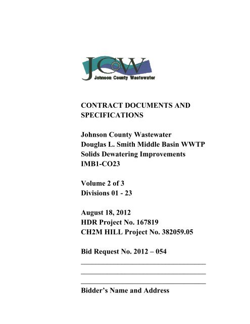
CONTRACT DOCUMENTS ANDSPECIFICATIONSJohnson County WastewaterDouglas L. Smith Middle Basin WWTPSolids Dewatering ImprovementsIMB1-CO23<strong>Vol</strong>ume 2 of 3Divisions 01 - 23August 18, 2012HDR Project No. 167819CH2M HILL Project No. 382059.05Bid Request No. 2012 – 054______________________________________________________________________________________________________Bidder’s Name and Address
CONTRACT DOCUMENTS ANDSPECIFICATIONSJohnson County WastewaterDouglas L. Smith Middle Basin WWTPSolids Dewatering ImprovementsIMB1-CO23August 18, 2012HDR Project No. 167819CH2M HILL Project No. 382059.05Bid Request No. 2012 – 054______________________________________________________________________________________________________Bidder’s Name and Address
TABLE OF CONTENTSPagesTECHNICAL SPECIFICATIONSDIVISION 1—GENERAL REQUIREMENTS01 11 00 Summary of Work .................................................................... 1- 101 26 00 Contract Modification Procedures ........................................... 1- 601 29 00 Payment Procedures ................................................................. 1- 301 31 13 Project Coordination ................................................................ 1- 1201 31 19 Project Meetings ...................................................................... 1- 301 32 00 <strong>Construction</strong> Progress Documentation .................................... 1- 701 33 00 Submittal Procedures ............................................................... 1- 801 42 13 Abbreviations and Acronyms ................................................... 1- 501 43 33 Manufacturers’ Field Services ................................................. 1- 4Supplements:Manufacturer’s Certificate of ComplianceManufacturer’s Certificate of Proper Installation.01 45 16.13 Contractor Quality Control ...................................................... 1- 901 45 33 Special Inspection and Testing ................................................ 1- 601 50 00 Temporary Facilities and Controls ........................................... 1- 1001 57 13 Temporary Erosion and Sediment Control .............................. 1- 601 61 00 Common Product Requirements .............................................. 1- 701 64 00 Owner-Furnished Products ...................................................... 1- 401 77 00 Closeout Procedures ................................................................. 1- 401 78 23 Operation and Maintenance Data ............................................. 1- 7Supplement:Equipment Record Form01 91 14 Equipment Testing and Facility Startup ................................... 1- 6Supplements:Unit Process Startup FormFacility Performance Demonstration/Certification FormDIVISION 2—EXISTING CONDITIONS02 41 00 Demolition ............................................................................... 1- 9DIVISION 3—CONCRETE03 01 32 Repair of Vertical and Overhead Concrete Surfaces ............... 1- 1203 01 33 Repair of Horizontal Concrete Surfaces .................................. 1- 1603 10 00 Concrete Forming and Accessories .......................................... 1- 503 15 00 Concrete Joints and Accessories .............................................. 1- 10PW/WBG/382059TABLE OF CONTENTSAUGUST 15, 2012 00 01 10 - 1©COPYRIGHT 2012 CH2M HILL
Pages03 21 00 Reinforcing Steel ..................................................................... 1- 603 30 00 Cast-In-Place Concrete ............................................................ 1- 26Supplements:Concrete Mix Design Data Sheets03 35 00 Concrete Finishing ................................................................... 1- 403 39 00 Concrete Curing ....................................................................... 1- 303 40 00 Precast Concrete ....................................................................... 1- 803 62 00 Nonshrink Grouting ................................................................. 1- 6Supplement:24-hour Evaluation of Nonshrink Grout Test Form and GroutTesting Procedures03 63 00 Concrete Doweling .................................................................. 1- 4DIVISION 4—MASONRY04 21 13.13 Masonry Veneer ....................................................................... 1- 1304 22 00 Concrete Unit Masonry ............................................................ 1- 14DIVISION 5—METALS05 05 23 Welding .................................................................................... 1- 5Supplement:Welding and Nondestructive Testing Table05 50 00 Metal Fabrications ................................................................... 1- 2405 52 00 Metal Railings .......................................................................... 1- 1105 53 00 Metal Gratings ......................................................................... 1- 5DIVISION 6—WOOD, PLASTICS, AND COMPOSITES06 10 00 Rough Carpentry ...................................................................... 1- 7DIVISION 7—THERMAL AND MOISTURE PROTECTION07 19 00 Water Repellents ...................................................................... 1- 407 21 00 Thermal Insulation ................................................................... 1- 307 52 16 SBS-Modified Bituminous Membrane Roofing ...................... 1- 907 62 00 Sheet Metal Flashing and Trim ................................................ 1- 907 70 01 Roof Specialties and Accessories ............................................ 1- 507 92 00 Joint Sealants ........................................................................... 1- 8TABLE OF CONTENTSPW/WBG/38205900 01 10 - 2 AUGUST 15, 2012©COPYRIGHT 2012 CH2M HILL
PagesDIVISION 8—OPENINGS08 06 01 Door and Hardware Schedule .................................................. 1- 1Supplement:Door and Hardware Schedule TableDoor and Frame Types08 11 16 Aluminum Doors and Frames .................................................. 1- 308 33 23 Overhead Coiling Doors .......................................................... 1- 508 41 13 Aluminum-Framed Entrances and Storefronts ........................ 1- 608 71 00 Door Hardware ......................................................................... 1- 908 80 00 Glazing ..................................................................................... 1- 908 90 00 Louvers..................................................................................... 1- 4Supplement:Louvers ScheduleDIVISION 9—FINISHES09 06 00 Schedules for Finishes ............................................................. 1- 1Supplements:Interior Finish Schedule09 90 00 Painting and Coating ................................................................ 1- 20Supplements:Paint System Data Sheet (PSDS)Product Data Sheet (PDS)DIVISION 10—SPECIALTIES10 14 00 Signage ..................................................................................... 1- 9Supplement:Sign Schedule10 44 00 Portable Fire and Safety Equipment ........................................ 1- 3DIVISION 11 THROUGH 21 (NOT USED)DIVISION 22—PLUMBING22 10 01.02 Polyvinyl ChlorideDrain Waste and Vent (PVC-DWV)Pipe and Fittings ...................................................................... 1- 122 10 01.08 Polyethylene (PE) Pipe and Fittings—Natural Gas Service ................................................................. 1- 222 40 00 Plumbing Fixtures .................................................................... 1- 5PW/WBG/382059TABLE OF CONTENTSAUGUST 15, 2012 00 01 10 - 3©COPYRIGHT 2012 CH2M HILL
PagesDIVISION 23—HEATING, VENTILATING, AND AIR-CONDITIONING (HVAC)23 05 93 Testing, Adjusting, and Balancing for HVAC ......................... 1- 523 09 00.01 HVAC Controls Sequence of Operation,General Control Types ............................................................. 1- 223 09 13 HVAC Controls, Field Components, and Instruments ............ 1- 223 31 13 Metal Ducts and Accessories ................................................... 1- 1723 31 16.16 Thermoset Fiberglass-Reinforced Plastic Ductsand Accessories ........................................................................ 1- 823 37 00 Air Outlets and Inlets ............................................................... 1- 223 77 00 Air Handling Units ................................................................... 1- 20Supplement:Data Sheet23 81 00 Unitary Air-Conditioning Equipment ...................................... 1- 11Supplement:Wall Mount Air Conditioner Data SheetDIVISION 24 THROUGH 25 (NOT USED)DIVISION 26—ELECTRICAL26 05 02 Basic Electrical Requirements ................................................. 1- 526 05 04 Basic Electrical Materials and Methods ................................... 1- 1426 05 05 Conductors ............................................................................... 1- 2526 05 26 Grounding and Bonding for Electrical Systems ....................... 1- 626 05 33 Raceway and Boxes ................................................................. 1- 2926 05 70 Electrical Systems Analysis ..................................................... 1- 9Supplement:Figure 1: Example Arc Flash Label26 08 00 Commissioning of Electrical Systems ..................................... 1- 3026 12 02 Oil-Filled Pad Mounted Transformers ..................................... 1- 126 13.16.02 Pad-Mounted Switchgear ......................................................... 1- 126 20 00 Low-<strong>Vol</strong>tage AC Induction Motors ......................................... 1- 1426 22 00 Low-<strong>Vol</strong>tage Transformers ...................................................... 1- 426 24 16 Panelboards .............................................................................. 1- 726 24 19 Low-<strong>Vol</strong>tage Motor Control .................................................... 1- 1426 27 26 Wiring Devices ........................................................................ 1- 1126 29 23 Low-<strong>Vol</strong>tage Adjustable Frequency Drive System .................. 1- 1526 41 00 Facility Lightning Protection ................................................... 1- 626 43 00 Transient <strong>Vol</strong>tage Suppression ................................................ 1- 526 50 00 Lighting .................................................................................... 1- 12TABLE OF CONTENTSPW/WBG/38205900 01 10 - 4 AUGUST 15, 2012©COPYRIGHT 2012 CH2M HILL
PagesDIVISION 27 (NOT USED)DIVISION 28—ELECTRONIC SAFETY AND SECURITY28 31 00 Fire Detection and Alarm ......................................................... 1- 23Supplement:Sequence of Operations MatrixDIVISION 29 THROUGH 30 (NOT USED)DIVISION 31—EARTHWORK31 10 00 Site Clearing ............................................................................. 1- 431 23 13 Subgrade Preparation ............................................................... 1- 331 23 16 Excavation................................................................................ 1- 531 23 19.01 Dewatering ............................................................................... 1- 331 23 23 Fill and Backfill ....................................................................... 1- 931 23 23.15 Trench Backfill ........................................................................ 1- 1131 32 00 Soil Stabilization ...................................................................... 1- 731 32 13.23 Fly Ash Subgrade Stabilization ................................................ 1- 631 32 19.16 Geotextile ................................................................................. 1- 931 41 00 Shoring ..................................................................................... 1- 131 63 29 Drilled Concrete Piers .............................................................. 1- 7DIVISION 32—EXTERIOR IMPROVEMENTS32 11 23 Aggregate Base Courses .......................................................... 1- 532 13 13 Concrete Paving ....................................................................... 1- 2032 16 00 Curbs and Gutters .................................................................... 1- 532 40 00 Modular Concrete Retaining Wall System .............................. 1- 732 91 13 Soil Preparation ........................................................................ 1- 332 92 00 Turf and Grasses ...................................................................... 1- 7DIVISION 33—UTILITIES33 05 14 Manhole and Structure Interior Coatings ................................. 1- 933 05 15 Manholes and Special Structures ............................................. 1- 1233 41 01 Storm Drain Piping .................................................................. 1- 533 41 01.03 Polyvinyl Chloride (PVC)........................................................ 1- 133 44 13.13 Catch Basins ............................................................................. 1- 4DIVISION 34 THROUGH 39 (NOT USED)PW/WBG/382059TABLE OF CONTENTSAUGUST 15, 2012 00 01 10 - 5©COPYRIGHT 2012 CH2M HILL
PagesDIVISION 40—PROCESS INTEGRATION40 05 15 Piping Support Systems ........................................................... 1- 10Supplements:Table 1: Nonchemical AreasTable 2: Chemical Areas40 27 00 Process Piping—General ......................................................... 1- 24Supplements:Piping Schedule LegendPiping Schedule40 27 00.01 Cement-Mortar, Glass and Ceramic-LinedDuctile Iron Pipe and Fittings .................................................. 1- 340 27 00.02 Carbon Steel Pipe and Fittings—Special Service .................... 1- 240 27 00.03 Carbon Steel Pipe and Fittings—General Service ................... 1- 440 27 00.08 Stainless Steel Pipe and Fittings—General Service ................. 1- 240 27 00.09 Stainless Steel Pipe and Fittings—Special Service ................. 1- 340 27 00.10 Polyvinyl Chloride (PVC) Pipe and Fittings ............................ 1- 240 27 00.11 Chlorinated Polyvinyl Chloride (CPVC) Pipe andFittings ..................................................................................... 1- 240 27 00.13 Copper and Copper Alloy Pipe, Tubing, and Fittings .............. 1- 140 27 01 Process Piping Specialties ........................................................ 1- 1540 42 13 Process Piping Insulation ......................................................... 1- 7Supplement:Service and Insulation Thickness Table40 80 01 Process Piping Leakage Testing ............................................... 1- 640 90 00 Instrumentation and Control for Process Systems ................... 1- 44Supplements:Loop SpecificationsInstrument ListPLC Input/Output ListLoop Status ReportInstrument Calibration SheetI&C Valve Adjustment SheetPerformance Test Sheet40 91 00 Instrumentation and Control Components ............................... 1- 1740 99 90 Package Control Systems ......................................................... 1- 17DIVISION 41 THROUGH 42 (NOT USED)TABLE OF CONTENTSPW/WBG/38205900 01 10 - 6 AUGUST 15, 2012©COPYRIGHT 2012 CH2M HILL
DIVISION 43—PROCESS GAS AND LIQUID HANDLING, PURIFICATION,AND STORAGE EQUIPMENTPages43 22 25 Centrifuge Rehabilitation ......................................................... 1- 5DIVISION 44—POLLUTION CONTROL EQUIPMENT44 42 56.10 Horizontal End Suction Centrifugal Pumps ............................. 1- 5Supplement:Data Sheet44 42 56.13 Progressing Cavity Pumps ....................................................... 1- 5Supplement:Data Sheet44 44 63.02 Polymer Feed System, Dry ....................................................... 1- 2144 46 13.02 Screw Conveyor System .......................................................... 1- 8Supplement:Induction Motor Data Sheet44 46 16 Belt Filter Press Dewatering Equipment .................................. 1- 29DIVISION 45 THROUGH 49 (NOT USED)DRAWINGS (BOUND SEPARATELY)END OF SECTIONPW/WBG/382059TABLE OF CONTENTSAUGUST 15, 2012 00 01 10 - 7©COPYRIGHT 2012 CH2M HILL
TECHNICAL SPECIFICATIONS
SECTION 01 11 00SUMMARY OF WORKPART 1GENERAL1.01 WORK COVERED BY CONTRACT DOCUMENTSA. The completed Work will provide Owner with solids dewateringimprovements and related items.1. Three new belt filter presses and associated piping and equipment.2. Thickening centrifuge system renewal and process modifications.3. New bulk dry polymer system and polymer room building addition.4. New electrical room building addition.5. Associated building and site improvements including; piping, HVAC,plumbing, electrical, and instrumentation.PART 2PART 3PRODUCTS (NOT USED)EXECUTION (NOT USED)END OF SECTIONPW/WBG/382059SUMMARY OF WORKAUGUST 15, 2012 01 11 00 - 1©COPYRIGHT 2012 CH2M HILL
SECTION 01 26 00CONTRACT MODIFICATION PROCEDURESPART 1GENERAL1.01 PROPOSAL REQUESTSA. Owner may, in anticipation of ordering an addition, deletion, or revision to theWork, request Contractor to prepare a detailed proposal of cost and times toperform contemplated change.B. Proposal request will include reference number for tracking purposes anddetailed description of and reason for proposed change, and such additionalinformation as appropriate and as may be required for Contractor to accuratelyestimate cost and time impact on Project.C. Proposal request is for information only; Contractor is neither authorized toexecute proposed change nor to stop Work in progress as result of suchrequest.D. Contractor’s written proposal shall be transmitted to Engineer promptly, butnot later than 14 days after Contractor’s receipt of Owner’s written request.Proposal shall remain firm for a maximum period of 45 days after receipt byEngineer.E. Owner’s request for proposal or Contractor’s failure to submit such proposalwithin the required time period will not justify a Claim for an adjustment inContract Price or Contract Times (or Milestones).1.02 CLAIMSA. Include, at a minimum:1. Specific references including (i) Drawing numbers, (ii) Specificationsection and article/paragraph number, and (iii) Submittal type, Submittalnumber, date reviewed, Engineer’s comment, as applicable, withappropriate attachments.2. Stipulated facts and pertinent documents, including photographs andstatements.3. Interpretations relied upon.4. Description of (i) nature and extent of Claim, (ii) who or what causedthe situation, (iii) impact to the Work and work of others, and(iv) discussion of claimant’s justification for requesting a change toprice or times or both.PW/WBG/382059CONTRACT MODIFICATIONAUGUST 15, 2012PROCEDURES©COPYRIGHT 2012 CH2M HILL 01 26 00 - 1
5. Estimated adjustment in price claimant believes it is entitled to with fulldocumentation and justification.6. Requested Change in Contract Times: Include at least (i) ProgressSchedule documentation showing logic diagram for request,(ii) documentation that float times available for Work have been used,and (iii) revised activity logic with durations including sub-networklogic revisions, duration changes, and other interrelated scheduleimpacts, as appropriate.7. Documentation as may be necessary as set forth below for Work ChangeDirective, and as Engineer may otherwise require.1.03 WORK CHANGE DIRECTIVESA. Procedures:1. Engineer will:a. Initiate, including a description of the Work involved and anyattachments.b. Affix signature, demonstrating Engineer’s recommendation.c. Transmit five copies to Owner for authorization.2. Owner will:a. Affix signature, demonstrating approval of the changes involved.b. Return four copies to Engineer, who will retain one copy, sendone copy to the Resident Project Representative or other fieldrepresentative, and forward two copies to Contractor.3. Upon completion of Work covered by the Work Change Directive orwhen final Contract Times and Contract Price are determined,Contractor shall submit documentation for inclusion in a Change Order.4. Contractor’s documentation shall include but not be limited to:a. Appropriately detailed records of Work performed to enabledetermination of value of the Work.b. Full information required to substantiate resulting change inContract Times and Contract Price for Work. On request ofEngineer, provide additional data necessary to supportdocumentation.c. Support data for Work performed on a unit price or Cost of theWork basis with additional information such as:1) Dates Work was performed, and by whom.2) Time records, wage rates paid, and equipment rental rates.3) Invoices and receipts for materials, equipment, andsubcontracts, all similarly documented.B. Effective Date of Work Change Directive: Date of signature by Owner, unlessotherwise indicated thereon.CONTRACT MODIFICATIONPW/WBG/382059PROCEDURES AUGUST 15, 201201 26 00 - 2 ©COPYRIGHT 2012 CH2M HILL
1.04 CHANGE ORDERSA. Procedure:1. Engineer will prepare six copies of proposed Change Order and transmitsuch with Engineer’s written recommendation and request to Contractorfor signature.2. Contractor shall, upon receipt, either: (i) promptly sign copies, retainingone for its file, and return remaining five copies to Engineer for Owner’ssignature, or (ii) return unsigned five copies with written justification fornot executing Change Order.3. Engineer will, upon receipt of Contractor signed copies, promptlyforward Engineer’s written recommendation and partially executedfive copies for Owner’s signature, or if Contractor fails to execute theChange Order, Engineer will promptly so notify Owner and transmitContractor’s justification to Owner.4. Upon receipt of Contractor-executed Change Order, Owner willpromptly either:a. Execute Change Order, retaining one copy for its file andreturning four copies to Engineer; orb. Return to Engineer unsigned copies with written justification fornot executing Change Order.5. Upon receipt of Owner-executed Change Order, Engineer will transmittwo copies to Contractor, one copy to Resident Project Representative orother field representative, and retain one copy, or if Owner fails toexecute the Change Order, Engineer will promptly so notify Contractorand transmit Owner’s justification to Contractor.6. Upon receipt of Owner-executed Change Order, Contractor shall:a. Perform Work covered by Change Order.b. Revise Schedule of Values to adjust Contract Price and submitwith next Application for Payment.c. Revise Progress Schedule to reflect changes in Contract Times, ifany, and to adjust times for other items of Work affected bychange.d. Enter changes in Project record documents after completion ofchange related Work.B. In signing a Change Order, Owner and Contractor acknowledge and agreethat:1. Stipulated compensation (Contract Price or Contract Times, or both) setforth includes payment for (i) the Cost of the Work covered by the ChangeOrder, (ii) Contractor’s fee for overhead and profit, (iii) interruption ofProgress Schedule, (iv) delay and impact, including cumulative impact, onother Work under the Contract Documents, and (v) extended overheads.PW/WBG/382059CONTRACT MODIFICATIONAUGUST 15, 2012PROCEDURES©COPYRIGHT 2012 CH2M HILL 01 26 00 - 3
2. Change Order constitutes full mutual accord and satisfaction for thechange to the Work.3. Unless otherwise stated in the Change Order, all requirements of theoriginal Contract Documents apply to the Work covered by the ChangeOrder.1.05 COST OF THE WORKA. In determining the supplemental costs allowed in Paragraph 11.01.A.5 of theGeneral Conditions for rental equipment and machinery, the following willapply.B. Rental of construction equipment and machinery and the parts thereof having areplacement value in excess of $1,000, whether owned by Contractor or rentedor leased from others, shall meet the following requirements:1. Full rental costs for leased equipment shall not exceed rates listed in theRental Rate Blue Book published by Equipment Watch, San Jose,California, as adjusted to the regional area of the Project. Ownedequipment costs shall not exceed the single shift rates established in theCost Reference Guide (CRG) also published by Equipment Watch. Themost recent published edition in effect at commencement of actualequipment use shall be used.2. Rates shall apply to equipment in good working condition. Equipment notin good condition, or larger than required, may be rejected by Engineer oraccepted at reduced rates.3. Leased Equipment: For equipment leased or rented in arm’s lengthtransactions from outside vendors, maximum rates shall be determined bythe following actual usage/Blue Book Payment Category:a. Less than 8 hours: Hourly Rate.b. 8 or more hours but less than 7 days: Daily Rate.c. 7 or more days but less than 30 days: Weekly Rate.d. 30 days or more: Monthly Rate.4. Arm’s length rental and lease transactions are those in which the firminvolved in the rental or lease of equipment is not associated with, ownedby, have common management, directorship, facilities and/or stockholderswith the firm renting the equipment.5. Leased Equipment in Use: Actual equipment use time documented byEngineer shall be the basis that equipment was on and utilized at theProject Site. In addition to the leasing rate above, equipment operationalcosts shall be paid at the estimated hourly operating cost rate set forth inthe Blue Book if not already included in the lease rate. Hours of operationshall be based upon actual equipment usage to the nearest quarter hour, asrecorded by Engineer.CONTRACT MODIFICATIONPW/WBG/382059PROCEDURES AUGUST 15, 201201 26 00 - 4 ©COPYRIGHT 2012 CH2M HILL
6. Leased Equipment, When Idle (Standby): Idle or standby equipment isequipment onsite or in transit to and from the Work Site and necessary toperform the Work under the modification, but not in actual use. Idleequipment time, as documented by Engineer, shall be paid at the leasingrate determined above, excluding operational costs.7. Owned and Other Equipment in Use: Equipment rates for ownedequipment or equipment provided in other than arm’s length transactionshall not exceed the single shift total hourly costs rate developed inaccordance with the CRG and as modified herein for multiple shifts. Thistotal hourly rate will be paid for each hour the equipment actuallyperforms work. Hours of operation shall be based upon actual equipmentusage as recorded by Engineer. This rate shall represent payment in fullfor Contractor’s direct costs.8. Owned and Other Equipment, When Idle (Standby): Equipment necessaryto be onsite to perform the Work on single shift operations, but notutilized, shall be paid for at the ownership hourly expense rate developedin accordance with the CRG, provided its presence and necessity onsitehas been documented by Engineer. Payment for idle time of portions of anormal workday, in conjunction with original contract Work, will not beallowed. In no event shall idle time claimed in a day for a particular pieceof equipment exceed the normal Work or shift schedule established for theProject. It is agreed that this rate shall represent payment in full forContractor’s direct costs. When Engineer determines that the equipment isnot needed to continuously remain at the Work Site, payment will belimited to actual hours in use.9. Owned and Other Equipment, Multiple Shifts: For multiple shiftoperations, the CRG single shift total hourly costs rate shall apply to theoperating equipment during the first shift. For subsequent shifts, up to 2 ina 24-hour day, operating rate shall be the sum of the total hourly CRGoperating cost and 60 percent of the CRG ownership and overhaulexpense. Payment for idle or standby time for second and third shifts shallbe 20 percent of the CRG ownership and overhaul expense.10. When necessary to obtain owned equipment from sources beyond theProject limits, the actual cost to transfer equipment to the Work Site andreturn it to its original location will be allowed as an additional item ofexpense. Move-in and move-out allowances will not be made forequipment brought to the Project if the equipment is also used on originalContract or related Work.11. If the move-out destination is not to the original location, payment formove-out will not exceed payment for move-in.12. If move is made by common carrier, the allowance will be the amountpaid for the freight. If equipment is hauled with Contractor’s own forces,rental will be allowed for the hauling unit plus the hauling unit operator’swage. If equipment is transferred under its own power, the rental will bePW/WBG/382059CONTRACT MODIFICATIONAUGUST 15, 2012PROCEDURES©COPYRIGHT 2012 CH2M HILL 01 26 00 - 5
1.06 FIELD ORDER75 percent of the appropriate total hourly costs for the equipment, withoutattachments, plus the equipment operator’s wage.13. Charges for time utilized in servicing equipment to ready it for use prior tomoving and similar charges will not be allowed.14. When a breakdown occurs on any piece of owned equipment, paymentshall cease for that equipment and any other owned equipment idled bythe breakdown.15. If any part of the Work is shut down by Owner, standby time will be paidduring nonoperating hours if diversion of equipment to other Work is notpracticable. Engineer reserves the right to cease standby time paymentwhen an extended shutdown is anticipated.16. If a rate has not been established in the CRG for owned equipment,Contractor may:a. If approved by Engineer, use the rate of the most similar modelfound, considering such characteristics as manufacturer, capacity,horsepower, age, and fuel type, orb. Request Equipment Watch to furnish a written response for a rateon the equipment, which shall be presented to Engineer forapproval; orc. Request Engineer to establish a rate.A. Engineer will issue Field Orders, with three copies to Contractor.B. Effective date of the Field Order shall be the date of signature by Engineer,unless otherwise indicated thereon.C. Contractor shall acknowledge receipt by signing and returning one copy toEngineer.D. Field Orders will be incorporated into subsequent Change Orders, as a no-costchange to the Contract.PART 2PART 3PRODUCTS (NOT USED)EXECUTION (NOT USED)END OF SECTIONCONTRACT MODIFICATIONPW/WBG/382059PROCEDURES AUGUST 15, 201201 26 00 - 6 ©COPYRIGHT 2012 CH2M HILL
SECTION 01 29 00PAYMENT PROCEDURESPART 1GENERAL1.01 SUBMITTALSA. Informational Submittals:1. Schedule of Estimated Progress Payments:a. Submit with initially acceptable Schedule of Values.b. Submit adjustments thereto with Application for Payment.2. Application for Payment.3. Final Application for Payment.1.02 SCHEDULE OF VALUESA. Prepare a separate Schedule of Values for each schedule of the Work underthe Agreement.B. Upon request of Engineer, provide documentation to support the accuracy ofthe Schedule of Values.C. Unit Price Work: Reflect unit price quantity and price breakdown fromconformed Bid Form.D. Lump Sum Work:1. List bonds and insurance premiums, mobilization, demobilization,preliminary and detailed progress schedule preparation, equipmenttesting, facility startup, and contract closeout separately.2. Break down by Division 2 through 49 with appropriate subdivision ofeach Specification for each Project facility.E. An unbalanced or front-end loaded schedule will not be acceptable.F. Summation of the complete Schedule of Values representing all the Workshall equal the Contract Price.G. Submit Schedule of Values in a spreadsheet format compatible with latestversion of Excel.1.03 SCHEDULE OF ESTIMATED PROGRESS PAYMENTSA. Show estimated payment requests throughout Contract Times aggregatinginitial Contract Price.PW/WBG/382059PAYMENT PROCEDURESAUGUST 15, 2012 01 29 00 - 1©COPYRIGHT 2012 CH2M HILL
B. Base estimated progress payments on initially acceptable progress schedule.Adjust to reflect subsequent adjustments in progress schedule and ContractPrice as reflected by modifications to the Contract Documents.1.04 APPLICATION FOR PAYMENTA. Transmittal Summary Form: Attach one Summary Form with each detailedApplication for Payment for each schedule and include Request for Paymentof Materials and Equipment on Hand as applicable. Execute certification byauthorized officer of Contractor.B. Use detailed Application for Payment Form suitable to Engineer.C. Provide separate form for each schedule as applicable.D. Include accepted Schedule of Values for each schedule or portion of lumpsum Work and the unit price breakdown for the Work to be paid on a unitpriced basis.E. Include separate line item for each Change Order and Work Change Directiveexecuted prior to date of submission. Provide further breakdown of such asrequested by Engineer.F. Preparation:1.05 PAYMENT1. Round values to nearest dollar.2. Submit Application for Payment, including a Transmittal SummaryForm and detailed Application for Payment Form(s) for each scheduleas applicable, a listing of materials on hand for each schedule asapplicable, and such supporting data as may be requested by Engineer.A. Payment for all Lump Sum Work shown or specified in Contract Documentsis included in the Contract Price. Payment will be based on a percentagecomplete basis for each line item of the accepted Schedule of Values.1.06 NONPAYMENT FOR REJECTED OR UNUSED PRODUCTSA. Payment will not be made for following:1. Loading, hauling, and disposing of rejected material.2. Quantities of material wasted or disposed of in manner not called forunder Contract Documents.3. Rejected loads of material, including material rejected after it has beenplaced by reason of failure of Contractor to conform to provisions ofContract Documents.PAYMENT PROCEDURESPW/WBG/38205901 29 00 - 2 AUGUST 15, 2012©COPYRIGHT 2012 CH2M HILL
4. Material not unloaded from transporting vehicle.5. Defective Work not accepted by Owner.6. Material remaining on hand after completion of Work.1.07 PARTIAL PAYMENT FOR STORED MATERIALS AND EQUIPMENTA. Partial Payment: No partial payments will be made for materials andequipment delivered or stored unless Shop Drawings and preliminaryoperation and maintenance data is acceptable to Engineer.B. Final Payment: Will be made only for products incorporated in Work;remaining products, for which partial payments have been made, shall revertto Contractor unless otherwise agreed, and partial payments made for thoseitems will be deducted from final payment.PART 2PART 3PRODUCTS (NOT USED)EXECUTION (NOT USED)END OF SECTIONPW/WBG/382059PAYMENT PROCEDURESAUGUST 15, 2012 01 29 00 - 3©COPYRIGHT 2012 CH2M HILL
SECTION 01 31 13PROJECT COORDINATIONPART 1GENERAL1.01 SUBMITTALSA. Informational:1. Photographs:a. Digital Images: Submit on compact disc within 5 days of beingtaken.2. Video Recordings: Submit two copies, including updated copy ofproject video log, within 5days of being taken.1.02 RELATED WORK AT SITEA. General:1. Other work that is either directly or indirectly related to scheduledperformance of the Work under these Contract Documents, listedhenceforth, is anticipated to be performed at Site by others.a. Contract 24, Douglas L. Smith Middle Basin Treatment Plant,Pavement Restoration.b. Contract 22, Douglas L. Smith Middle Basin Treatment Plant,Building No. 1 and No. 6 Improvements.2. Coordinate the Work of these Contract Documents with work of othersas specified in General Conditions.3. Include sequencing constraints specified herein as a part of ProgressSchedule.B. Power:1. Agency and Contact Person: Kansas City Power and Light (KCPL) JohnWienstroer, telephone number: 913-894-3074.2. Work to be performed by Contractor: Coordinate connection of newreplacement primary feeders from 12.47 KV switchgear serving SolidsProcessing Building.1.03 OWNER-FURNISHED PRODUCTSA. Two (2) Pad-mounted switchgear.B. Two (2) 750 KVA oil-filled pad-mounted transformers.PW/WBG/382059PROJECT COORDINATIONAUGUST 15, 2012 01 31 13 - 1©COPYRIGHT 2012 CH2M HILL
C. Contractor shall coordinate directly with Supplier with respect to delivery andunloading. If delivery is delayed by Owner or Supplier beyond the datesindicated, a change in Contract Time will be processed with no change inContract Price.1.04 UTILITY NOTIFICATION AND COORDINATIONA. Coordinate the Work with various utilities within Project limits. Notifyapplicable utilities prior to commencing Work, if damage occurs, or ifconflicts or emergencies arise during Work.1. Electricity Company: Kansas City Power and Light.a. Contact Person: John Wienstroer.b. Telephone: 913-894-3074.2. Telephone Company: AT&T.a. Contact Person: Pauletta Easter.b. Telephone: 877-377-0975.3. Gas Company: Atmos Energy Corporation.a. Contact Person: Tony Benedict.b. Telephone: 913-254-6344.1.05 PROJECT MILESTONESA. General: Include the Milestones specified herein as a part of the ProgressSchedule required under Section 01 32 00, <strong>Construction</strong> ProgressDocumentation.1.06 FACILITY OPERATIONSA. Continuous operation of Owner’s facilities is of critical importance. Scheduleand conduct activities to enable existing facilities to operate continuously,unless otherwise specified.B. Perform Work continuously during critical connections and changeovers, andas required to prevent interruption of Owner’s operations.C. When necessary, plan, design, and provide various temporary services,utilities, connections, temporary piping and heating, access, and similar itemsto maintain continuous operations of Owner’s facility.D. Do not close lines, open or close valves, or take other action which wouldaffect the operation of existing systems, except as specifically required by theContract Documents and after authorization by Owner and Engineer. Suchauthorization will be considered within 48 hours after receipt of Contractor’swritten request.PROJECT COORDINATIONPW/WBG/38205901 31 13 - 2 AUGUST 15, 2012©COPYRIGHT 2012 CH2M HILL
E. Construct Work in the following stages to allow for Owner’s continuousoccupancy and for uninterrupted operation during construction. Note: Thefollowing sequencing steps are intended to provide general guidance to theContractor. Contractor shall be responsible for preparing detailed sequencingplans for each stage of the Work. Submit preliminary plans no less than21 days prior to initiating the stage and coordinate with Engineer and Ownerto finalize plan no less than 7 days prior to initiating the stage. Sequencesother than those specified will be considered upon written request to Ownerand Engineer, provided they afford equivalent continuity of operations.1. Site Utilization:a. Concurrent Work at the site under Contracts 22 and 24 mayrequire coordination between contractors with respect to siteutilization, access, storage, staging, scheduling, deliveries, etc.The Contract 23 Contractor shall coordinate as required, and shallattend all Contract 22 and 24 coordination meetings, if applicable,in which overlapping operations are discussed.b. Specific requirements with respect to storage areas, access routes,etc., are shown on the Drawings.c. Truck access to grit area from south, sludge bay from north andsouth, and sludge loading station from north shall be maintained atall times. Brief service interruptions shall be coordinated withOwner and Engineer. One of the two east west roads locatedimmediately north and south of the Solids Processing Buildingshall be kept open to traffic at all times.2. Medium <strong>Vol</strong>tage Electrical System Modifications - Milestone 1(60 Days from Notice to Proceed):a. Construct new primary ductbanks between existing 15 KVmanhole and location of new pad-mounted loop switches and padmountedtransformers.b. Power the Solids Processing Building from existingTransformer T8 and remove existing Transformer T2, and theductbanks to the loop switch and existing motor control centerMCC-9.c. Install temporary conduits from the location of new pad-mountedtransformer T2 to the temporary service disconnect switchlocation, and from the location of the temporary servicedisconnect switch to Side A of existing motor control centerMCC-9.d. Construct new secondary ductbank from location of new padmountedTransformers T2 and T8, to the location of the newservice entrance main disconnect MCC-9-SE (Sides A and B) inthe new electrical room. Coordinate the routing of the conduitswith the location of the structural piles.PW/WBG/382059PROJECT COORDINATIONAUGUST 15, 2012 01 31 13 - 3©COPYRIGHT 2012 CH2M HILL
e. Construct new concrete pads for new Owner provided loopswitches and transformers.f. Mount new Owner-provided loop switches and transformers.g. Install primary conductors between loop switches andtransformers.h. Construct new concrete pad and install the temporary servicedisconnect switch.i. Install temporary conductors between new Transformer T2 totemporary service disconnect, and between the temporary servicedisconnect and Side A of existing MCC-9.j. Power the Final Basin Pump Station from Transformer T9 andSettled Sewage Pump Station from Transformer T10.k. Remove existing primary conductors from the main 12.47 KVswitchgear to existing T2 loop switch, and from existing T2 loopswitch to existing T3 loop switch.l. Install new primary conductors from the main 12.47 KVswitchgear to new T2 loop switch, and from new T2 loop switchto existing T3 loop switch.m. Power the Solids Processing Building from new Transformer T2,the Final Basin Pump Station from Transformer T3 and SettledSewage Pump Station form Transformer T4.n. Remove the existing loop switches for both T2 and T8 andassociated ductbanks.o. Remove existing Transformer T8 and associated ductbank.p. Remove existing primary conductors from the main 12.47 KVswitchgear to existing T8 loop switch, and from existing T8 loopswitch to existing T9 loop switch.q. Install new primary conductors from the main 12.47 KVswitchgear to new T8 loop switch, and from new T8 loop switchto existing T9 loop switch.r. Power the Solids Processing Building from new Transformers T2,the Final Basin Pump Station from both Transformers T3 and T9and Settled Sewage Pump Station from both Transformers T4 andT10.3. Electrical Room Addition and Low <strong>Vol</strong>tage Switchgear - Milestone 2(240 Days from Notice to Proceed):a. Prior to commencing construction activities associated with thenew Electrical Room, Contractor shall complete the following:1) Complete all Work under Milestone 1.2) Either temporarily relocate existing MAU-7005 to providecontinued heating/ventilation to the Belt Filter Press Roomor remove MAU-7005 and provide temporary heating /ventilation of equivalent capacity (minimum six air changesPROJECT COORDINATIONPW/WBG/38205901 31 13 - 4 AUGUST 15, 2012©COPYRIGHT 2012 CH2M HILL
per hour). Heating shall be provided when ambienttemperatures are below 55 degrees F.3) Relocate Exhaust Fans EF-7001 and EF-7002 servingexisting Centrifuge Room as shown on Drawings.b. Perform required site demolition, excavation and surfacepreparation as required to install concrete foundation piers.c. Install conduits from the location of new service entrance maindisconnect MCC-9-SE (Sides A and B) to the first pull-box in thebasement of the Solids Processing Building. Coordinate therouting of the conduits with the location of the structural piles.d. Install conduits from first pull-box to Side B of existing MCC-9.e. Construct building foundation and base slab concrete,masonry/brick walls, roofing system and access doors to provide acomplete building enclosure.f. Install new MAU-7005 and associated exterior ductwork.g. Install MCC-9-SE, the secondary conductors from newTransformer T8 to Side B of MCC-9-SE, and the conductors fromSide B of MCC-9-SE to Side B of existing MCC-9.h. Power the Solids Process Building from new Transformer T8 andremove the temporary service disconnect switch, ductbanks andconductors.i. Install conduits from first pull-box to Side A of existing MCC-9.j. Install the secondary conductors from new Transformer T2 toSide A of MCC-9-SE, and the conductors from Side A ofMCC-9-SE to side A of existing MCC-9.k. Power the Solids Process Building from both newTransformers T2 and T8.l. Install MCC 2 and building HVAC systems. Building HVACsystems shall be confirmed to be operating correctly prior totransferring existing and connecting new electrical loads to newMCC 2.m. Transfer existing loads to new MCC 2.n. Once new MCC 2 has been confirmed to be operating properly,demolish existing MCC 2 and unused/abandoned conduits andwiring.4. SCADA Switchover - Milestone 3 (270 Days from Notice to Proceed).a. Milestone 3 Work shall not commence until all Work underMilestone 2 has been completed.b. Confirm existing active signals for existing PLC-8001, and whichsignals are no longer active.c. Relocate existing PLC-8001 to new location in new ElectricalRoom.PW/WBG/382059PROJECT COORDINATIONAUGUST 15, 2012 01 31 13 - 5©COPYRIGHT 2012 CH2M HILL
d. Reconnect all existing active signals to PLC-8001 and connectPLC-8001 into plant network. New signals will be connected andprogramming performed as Work proceeds.e. A maximum duration of 7 calendar days will be allowed in whichPLC-8001 can be out of service.5. Polymer Room Addition:a. Perform required site demolition, excavation and surfacepreparation as required to install concrete foundation piers.b. Demolish portions of building indicated. Provide suitabletemporary protection against weather, dust, and constructiondebris. Submit protection plan to Owner and Engineer forapproval. Provide temporary heating, if required, to maintain roomtemperature above 55 degrees F.c. Install under slab piping and construct building foundation andbase slab concrete, masonry/brick walls, roofing system andaccess doors to provide a complete building enclosure.d. Install dry polymer feed system (bulk bag frame/volumetricfeeder, mixing tanks and transfer pumps) in new Polymer RoomAddition. Polymer feed to two belt filter press units must bemaintained at all times except for deviations as described herein.1) Contractor may use the new polymer feed system totemporarily feed polymer solution to the belt filter pressequipment provided it provides the same capability andredundancy as the existing polymer system, and theContractor operates the system in the temporary mode andthe temporary arrangements are acceptable to the Owner andEngineer.e. Demolish existing polymer feed system and associated piping asshown on Drawings.f. Install permanent polymer feed system (aging tanks and centrifugeand belt filter press polymer feed pumps). If Contractor utilizesbelt filter press polymer feed pumping equipment in a temporaryarrangement, relocation of applicable pumping equipment to finallocation as shown on Drawings shall be limited to no more than1 day with 2 weeks prior notice provided to Owner and Engineer.6. Belt Filter Press No. 3 and Related Systems - Milestone 4 (300 Daysfrom Notice to Proceed):a. Install supplemental columns as shown on Drawings. Temporarilyrelocate and reconnect piping/conduit as required that is in conflictwith proposed column locations.b. Install BFP 3 curbs and structural supports.c. Install all piping (sludge feed, washwater drain, filtrate, planteffluent water and polymer solution) associated with Belt FilterPress No. 3.PROJECT COORDINATIONPW/WBG/38205901 31 13 - 6 AUGUST 15, 2012©COPYRIGHT 2012 CH2M HILL
d. Install Belt Filter Press No. 3 and ancillary equipment.e. Modify Belt Filter Press Control Room North wall and install BeltFilter Press No. 3 control panel and provide temporary connectionto plant SCADA system. Note: SCADA workshops, programmingand SCADA screen design for the project must be completed priorto this point.f. Coordinate work so as to maintain two belt filter press units inoperation at all times.7. Belt Filter Presses No. 1 and No. 2 and Related Systems:a. Remove existing Belt Filter Press No. 1, associated ancillaryequipment, and control panel.b. Remove existing curb and structural supports and construct newcurb and structural supports for new Belt Filter Press No. 1.c. Install all piping (sludge feed, washwater drain, filtrate, planteffluent water and polymer solution) associated with Belt FilterPress No. 1.d. Install Belt Filter Press No. 1 and ancillary equipment.e. Install Belt Filter Press No. 1 control panel and establishpermanent SCADA connection as specified.f. Achieve successful operation (manual mode minimum) of BeltFilter Press No. 1.g. Repeat Items a. through f. for Belt Filter Press No. 2.8. Centrifuge and Recuperative Thickening:a. Install piping, valves and instrumentation associated withRecuperative Thickening (RT) up to connection point withexisting WAS piping.b. Remove one centrifuge to be rehabilitated. Only one of the twounits to be rehabilitated may be removed at a time.c. Connect RT piping to existing WAS force mains so as to maintainone force main in operation at all times. Coordinate force maindowntimes with centrifuge removal to maintain ability to alwaysfeed active centrifuges. Coordinate Polymer Injection Ring (PIR)installation into WAS feed piping to centrifuges to coincide withcorresponding force main downtime and/or centrifuge removal.Two centrifuges shall remain in operation at all times.d. Replace existing TWAS pumps at centrifuge discharge hopper soas to maintain one pump in service at all times.9. Belt Filter Press Room Ventilation Modifications:a. Demolish existing odor control ductwork and install newductwork as shown on Drawings.1) Odor control system operates under negative pressureinduced through fans located in Building No. 6. The odorcontrol duct penetration at existing West building wall willcontinue to draw odorous air from the belt filter press roomPW/WBG/382059PROJECT COORDINATIONAUGUST 15, 2012 01 31 13 - 7©COPYRIGHT 2012 CH2M HILL
until connected to new odor control ductwork as shown onDrawings.b. Install new supply air ductwork as shown on Drawings.10. Site Restoration and Paving: To be completed after all site work,building construction, and major equipment material deliveries havebeen completed. Paving replacement shall be done in two separableparts of work, north and south, in order to maintain Owner access toSolids Processing Building for dewatered cake and grit removal as wellas offsite sludge unloading.F. Process or Facility Shutdown:1. Provide 7 days advance written request for approval of need to shutdown a process or facility to Owner and Engineer.2. Power outages will be considered upon 72 hours written request toOwner and Engineer. Describe the reason, anticipated length of time,and areas affected by the outage. Provide temporary provisions forcontinuous power supply to critical facility components.3. Whole plant power outages will be limited to a duration of 2 hours andmust be scheduled during middle of night, dry weather, and low flowperiods.G. Install and maintain bypass facilities and temporary connections required tokeep Owner’s wastewater treatment and biosolids processing operations online.H. Do not proceed with Work affecting a facility’s operation without obtainingOwner’s and Engineer’s advance approval of the need for and duration of suchWork.I. Relocation of Existing Facilities:1. During construction, it is expected that minor relocations of Work willbe necessary.2. Provide complete relocation of existing structures, including piping,utilities, equipment, electrical conduit wiring, electrical duct bank, andother necessary items.3. Use only new materials for relocated facility. Match materials ofexisting facility, unless otherwise shown or specified.4. Perform relocations to minimize downtime of existing facilities.5. Install new portions of existing facilities in their relocated position priorto removal of existing facilities, unless otherwise accepted by Engineer.J. Conduct coordination meeting prior to any shutdown, tie-in or startup todiscuss the following:PROJECT COORDINATIONPW/WBG/38205901 31 13 - 8 AUGUST 15, 2012©COPYRIGHT 2012 CH2M HILL
1. Roles and responsibilities of the Contractor, Engineer and Owner.2. Review of the scheduled sequence of work.3. Review of the Contractor’s proposed means and methods.4. Temporary operation requirements and/or limitations.5. Safety concerns and regulations. (Confined space requirements, gasdetectors, emergency procedures, contact numbers, any after normalwork hour restrictions.)6. Lock out/tag out procedures.7. Preparation of contingency plan to deal with unforeseen conditions thatwill delay the scheduled shutdown work completion and/or affect plantoperations.1.07 ADJACENT FACILITIES AND PROPERTIESA. Examination:1. After Effective Date of the Agreement and before Work at Site isstarted, Contractor, Engineer, and affected property owners and utilityowners shall make a thorough examination of pre-existing conditionsincluding existing buildings, structures, and other improvements invicinity of Work, as applicable, which could be damaged byconstruction operations.2. Periodic reexamination shall be jointly performed to include, but notlimited to, cracks in structures, settlement, leakage, and similarconditions.B. Documentation:1. Record and submit documentation of observations made on examinationinspections.2. Upon receipt, Engineer will review, sign, and return one record copy ofdocumentation to Contractor to be kept on file in field office.3. Such documentation shall be used as indisputable evidence inascertaining whether and to what extent damage occurred as a result ofContractor’s operations, and is for the protection of adjacent propertyowners, Contractor, and Owner.1.08 CONSTRUCTION PHOTOGRAPHSA. Photographically document all phases of the project including preconstruction,construction progress, and post-construction.B. Photography shall be by a professional commercial photographer, experiencedin shooting interior/exterior construction photos, in daylight and nighttimeconditions, and in good and inclement weather.PW/WBG/382059PROJECT COORDINATIONAUGUST 15, 2012 01 31 13 - 9©COPYRIGHT 2012 CH2M HILL
C. Engineer shall have the right to select the subject matter and vantage pointfrom which photographs are to be taken.D. Preconstruction and Post-<strong>Construction</strong>:1. After Effective Date of the Agreement and before Work at Site isstarted, and again upon issuance of Substantial Completion, take aminimum of 48 exposures of <strong>Construction</strong> Site and property adjacent toperimeter of <strong>Construction</strong> Site.2. Particular emphasis shall be directed to structures both inside andoutside the Site.3. Format: Digital.E. <strong>Construction</strong> Progress Photos:1. Photographically demonstrate progress of construction, showing everyaspect of Site and adjacent properties as well as interior and exterior ofnew or impacted structures.2. Weekly: Take 20 exposures using digital.3. Monthly: Take 50 exposures using digital.F. Digital Images:1. Archive using a commercially available photo management system.2. Label each compact disk with Project and Owner’s name, and week andyear images were produced.1.09 REFERENCE POINTS AND SURVEYSA. Owner’s Responsibilities:1. Establish bench marks convenient to Work and at least every 500 feet onpipelines and roads.2. Establish horizontal reference points or coordinate system with benchmarks and reference points for Contractor’s use as necessary to lay outWork.B. Location and elevation of bench marks are shown on Drawings.C. Contractor’s Responsibilities:1. Provide additional survey and layout required to layout the Work.2. Notify Engineer at least 3 working days in advance of time when gradeand line to be provided by Owner will be needed.3. Check and establish exact location of existing facilities prior toconstruction of new facilities and any connections thereto.PROJECT COORDINATIONPW/WBG/38205901 31 13 - 10 AUGUST 15, 2012©COPYRIGHT 2012 CH2M HILL
4. In event of discrepancy in data or staking provided by Owner, requestclarification before proceeding with Work.5. Retain professional land surveyor or civil engineer registered in state ofProject who shall perform or supervise engineering surveying necessaryfor additional construction staking and layout.6. Maintain complete accurate log of survey Work as it progresses as aRecord Document.7. On request of Engineer, submit documentation.8. Provide competent employee(s), tools, stakes, and other equipment andmaterials as Engineer may require to:a. Establish control points, lines, and easement boundaries.b. Check layout, survey, and measurement Work performed byothers.c. Measure quantities for payment purposes.PART 2PART 3PRODUCTS (NOT USED)EXECUTION3.01 SALVAGE OF MATERIALSA. Coordinate items to be salvaged with Engineer/Owner. Where applicable,remove material/equipment with extreme care so as not to damage for futureuse.3.02 CUTTING, FITTING, AND PATCHINGA. Cut, fit, adjust, or patch Work and work of others, including excavation andbackfill as required, to make Work complete.B. Obtain prior written authorization of Engineer and Owner before commencingWork to cut or otherwise alter:1. Structural or reinforcing steel, structural column or beam, elevated slab,trusses, or other structural member.2. Weather- or moisture-resistant elements.3. Efficiency, maintenance, or safety of element.4. Work of others.C. Refinish surfaces to provide an even finish.1. Refinish continuous surfaces to nearest intersection.2. Refinish entire assemblies.3. Finish restored surfaces to such planes, shapes, and textures that notransition between existing work and Work is evident in finishedsurfaces.PW/WBG/382059PROJECT COORDINATIONAUGUST 15, 2012 01 31 13 - 11©COPYRIGHT 2012 CH2M HILL
D. Restore existing work, Underground Facilities, and surfaces that are to remainin completed Work including concrete-embedded piping, conduit, and otherutilities as specified and as shown.E. Make restorations with new materials and appropriate methods as specified fornew Work of similar nature; if not specified, use recommended practice ofmanufacturer or appropriate trade association.F. Fit Work airtight to pipes, sleeves, ducts, conduit, and other penetrationsthrough surfaces and fill voids.G. Remove specimens of installed Work for testing when requested by Engineer.END OF SECTIONPROJECT COORDINATIONPW/WBG/38205901 31 13 - 12 AUGUST 15, 2012©COPYRIGHT 2012 CH2M HILL
SECTION 01 31 19PROJECT MEETINGSPART 1GENERAL1.01 GENERALA. Engineer will schedule physical arrangements for meetings throughoutprogress of the Work, prepare meeting agenda with regular participant inputand distribute with written notice of each meeting, preside at meetings, recordminutes to include significant proceedings and decisions, and reproduce anddistribute copies of minutes within 3 days after each meeting to participantsand parties affected by meeting decisions.1.02 PRECONSTRUCTION CONFERENCEA. Contractor shall be prepared to discuss the following subjects, as a minimum:1. Required schedules.2. Status of Bonds and insurance.3. Sequencing of critical path work items.4. Progress payment procedures.5. Project changes and clarification procedures.6. Use of Site, access, office and storage areas, security and temporaryfacilities.7. Major product delivery and priorities.8. Contractor’s safety plan and representative.B. Attendees will include:1. Owner’s representatives.2. Contractor’s office representative.3. Contractor’s resident superintendent.4. Contractor’s quality control representative.5. Subcontractors’ representatives whom Contractor may desire orEngineer may request to attend.6. Engineer’s representatives.7. Others as appropriate.1.03 PRELIMINARY SCHEDULES REVIEW MEETINGA. As set forth in General Conditions and Section 01 32 00, <strong>Construction</strong>Progress Documentation.PW/WBG/382059PROJECT MEETINGSAUGUST 15, 2012 01 31 19 - 1©COPYRIGHT 2012 CH2M HILL
1.04 PROGRESS MEETINGSA. Engineer will schedule regular progress meetings at Site, conducted bi-weeklyto review the Work progress, Progress Schedule, Schedule of Submittals,Application for Payment, contract modifications, and other matters needingdiscussion and resolution.B. Attendees will include:1. Owner’s representative(s), as appropriate.2. Contractor, Subcontractors, and Suppliers, as appropriate.3. Engineer’s representative(s).4. Others as appropriate.1.05 QUALITY CONTROL MEETINGSA. In accordance with Section 01 45 16.13, Contractor Quality Control.1.06 PROCESS INSTRUMENTATION AND CONTROL SYSTEMS (PICS)COORDINATION MEETINGSA. Engineer will schedule meetings at Site, conducted bi-monthly to reviewspecific requirements of PICS work.B. Attendees will include:1. Contractor.2. Owner.3. PICS Subcontractor/Installer.4. Engineer’s representatives.1.07 PREINSTALLATION MEETINGSA. When required in individual Specification sections, convene at Site prior tocommencing the Work of that section.B. Require attendance of entities directly affecting, or affected by, the Work ofthat section.C. Notify Engineer 4 days in advance of meeting date.D. Provide suggested agenda to Engineer to include reviewing conditions ofinstallation, preparation and installation or application procedures, andcoordination with related Work and work of others.PROJECT MEETINGSPW/WBG/38205901 31 19 - 2 AUGUST 15, 2012©COPYRIGHT 2012 CH2M HILL
1.08 FACILITY STARTUP MEETINGSA. Schedule and attend a minimum of two facility startup meetings. The first ofsuch meetings shall be held prior to submitting Facility Startup Plan, asspecified in Section 01 91 14, Equipment Testing and Facility Startup, andshall include preliminary discussions regarding such plan.B. Agenda items shall include, but not be limited to, content of Facility StartupPlan, coordination needed between various parties in attendance, and potentialproblems associated with startup.C. Attendees will include:1. Contractor.2. Contractor’s designated quality control representative.3. Subcontractors and equipment manufacturer’s representatives whomContractor deems to be directly involved in facility startup.4. Engineer’s representatives.5. Owner’s operations personnel.6. Others as required by Contract Documents or as deemed necessary byContractor.1.09 OTHER MEETINGSA. In accordance with Contract Documents and as may be required by Owner andEngineer.PART 2PART 3PRODUCTS (NOT USED)EXECUTION (NOT USED)END OF SECTIONPW/WBG/382059PROJECT MEETINGSAUGUST 15, 2012 01 31 19 - 3©COPYRIGHT 2012 CH2M HILL
SECTION 01 32 00CONSTRUCTION PROGRESS DOCUMENTATIONPART 1GENERAL1.01 SUBMITTALSA. Informational Submittals:1. Preliminary Progress Schedule: Submit within time specified inparagraph 2.05 of the General Conditions.2. Detailed Progress Schedule:a. Submit initial Detailed Progress Schedule within 60 days afterEffective Date of the Agreement.b. Submit an Updated Progress Schedule at each update, inaccordance with Article Detailed Progress Schedule.3. Submit with Each Progress Schedule Submission:a. Contractor’s certification that Progress Schedule submission isactual schedule being utilized for execution of the Work.b. File compatible with latest version of SureTrak Project Managerby Primavera Systems, Inc. unless otherwise approved byEngineer.c. Progress Schedule: Three legible copies.d. Narrative Progress Report: Same number of copies as specifiedfor Progress Schedule.4. Prior to final payment, submit a final Updated Progress Schedule.1.02 PRELIMINARY PROGRESS SCHEDULEA. In addition to basic requirements outlined in General Conditions, show adetailed schedule, beginning with Notice to Proceed, for minimum duration of90 days, and a summary of balance of Project through Final Completion.B. Show activities including, but not limited to the following:1. Notice to Proceed.2. Permits.3. Submittals, with review time. Contractor may use Schedule ofSubmittals specified in Section 01 33 00, Submittal Procedures.4. Early procurement activities for long lead equipment and materials.5. Initial Site work.6. Earthwork.7. Specified Work sequences and construction constraints.8. Contract Milestone and Completion Dates.9. Owner-furnished products delivery dates or ranges of dates, ifapplicable.PW/WBG/382059CONSTRUCTION PROGRESSAUGUST 15, 2012DOCUMENTATION©COPYRIGHT 2012 CH2M HILL 01 32 00 - 1
10. Major structural, mechanical, equipment, electrical, architectural, andinstrumentation and control Work.11. System startup summary.12. Project close-out summary.13. Demobilization summary.C. Update Preliminary Progress Schedule monthly as part of progress paymentprocess. Failure to do so may result in the Owner withholding all or part of themonthly progress payment until the Preliminary Progress Schedule is updatedin a manner acceptable to Engineer.D. Format: In accordance with Article Progress Schedule—Critical PathNetwork.1.03 DETAILED PROGRESS SCHEDULEA. In addition to requirements of General Conditions, submit Detailed ProgressSchedule beginning with Notice to Proceed and continuing through FinalCompletion.B. Show the duration and sequences of activities required for completeperformance of the Work reflecting means and methods chosen by Contractor.C. When accepted by Engineer, Detailed Progress Schedule will replacePreliminary Progress Schedule and become Baseline Schedule. Subsequentrevisions will be considered as Updated Progress Schedules.D. Format: In accordance with Article Progress Schedule—Critical PathNetwork.E. Update monthly to reflect actual progress and occurrences to date, includingweather delays.1.04 PROGRESS SCHEDULE—CRITICAL PATH NETWORKA. General: Comprehensive computer-generated schedule using CPM, generallyas outlined in Associated General Contractors of America (AGC) 580,“<strong>Construction</strong> Project Planning and Scheduling Guidelines.” If a conflictoccurs between the AGC publication and this Specification, this Specificationshall govern.B. Contents:1. Schedule shall begin with the date of Notice to Proceed and concludewith the date of Final Completion.2. Identify Work calendar basis using days as a unit of measure.CONSTRUCTION PROGRESSPW/WBG/382059DOCUMENTATION AUGUST 15, 201201 32 00 - 2 ©COPYRIGHT 2012 CH2M HILL
3. Show complete interdependence and sequence of construction andProject-related activities reasonably required to complete the Work.4. Identify the Work of separate stages and other logically groupedactivities, and clearly identify critical path of activities.5. Reflect sequences of the Work, restraints, delivery windows, reviewtimes, Contract Times and Project Milestones set forth in the Agreementand Section 01 31 13, Project Coordination.6. Include as applicable, at a minimum:a. Obtaining permits, submittals for early product procurement, andlong lead time items.b. Mobilization and other preliminary activities.c. Initial Site work.d. Specified Work sequences, constraints, and Milestones, includingSubstantial Completion date(s) Subcontract Work.e. Major equipment design, fabrication, factory testing, and deliverydates.f. Delivery dates for Owner-furnished products, as specified inSection 01 11 00, Summary of Work.g. Sitework.h. Concrete Work.i. Structural steel Work.j. Architectural features Work.k. Conveying systems Work.l. Equipment Work.m. Mechanical Work.n. Electrical Work.o. Instrumentation and control Work.p. Interfaces with Owner-furnished equipment.q. Other important Work for each major facility.r. Equipment and system startup and test activities.s. Project closeout and cleanup.t. Demobilization.7. Activity duration for Submittal review shall not be less than review timespecified unless clearly identified and prior written acceptance has beenobtained from Engineer.C. Network Graphical Display:1. Plot or print on paper not greater than 30 inches by 42 inches or smallerthan 22 inches by 34 inches, unless otherwise approved.2. Title Block: Show name of Project, Owner, date submitted, revision orupdate number, and the name of the scheduler. Updated schedules shallindicate data date.3. Identify horizontally across top of schedule the time frame by year,month, and day.PW/WBG/382059CONSTRUCTION PROGRESSAUGUST 15, 2012DOCUMENTATION©COPYRIGHT 2012 CH2M HILL 01 32 00 - 3
4. Identify each activity with a unique number and a brief description ofthe Work associated with that activity.5. Indicate the critical path.6. Show, at a minimum, the controlling relationships between activities.7. Plot activities on a time-scaled basis, with the length of each activityproportional to the current estimate of the duration.8. Plot activities on an early start basis unless otherwise requested byEngineer.9. Provide a legend to describe standard and special symbols used.D. Schedule Report:1. On 8-1/2-inch by 11-inch white paper, unless otherwise approved.2. List information for each activity in tabular format, including at aminimum:a. Activity Identification Number.b. Activity Description.c. Original Duration.d. Remaining Duration.e. Early Start Date (Actual start on Updated Progress Schedules).f. Early Finish Date (Actual finish on Updated Progress Schedules).g. Late Start Date.h. Late Finish Date.i. Total Float.3. Sort reports, in ascending order, as listed below:a. Activity number sequence with predecessor and successoractivity.1.05 PROGRESS OF THE WORKA. Updated Progress Schedule shall reflect:1. Progress of Work to within 5 working days prior to submission.2. Approved changes in Work scope and activities modified sincesubmission.3. Delays in Submittals or resubmittals, deliveries, or Work.4. Adjusted or modified sequences of Work.5. Other identifiable changes.6. Revised projections of progress and completion.7. Report of changed logic.B. Produce detailed subschedules during Project, upon request of Owner orEngineer, to further define critical portions of the Work such as facilityshutdowns.C. If Contractor fails to complete activity by its latest scheduled completion dateand this Failure is anticipated to extend Contract Times (or Milestones),CONSTRUCTION PROGRESSPW/WBG/382059DOCUMENTATION AUGUST 15, 201201 32 00 - 4 ©COPYRIGHT 2012 CH2M HILL
Contractor shall, within 7 days of such failure, submit a written statement asto how Contractor intends to correct nonperformance and return to acceptablecurrent Progress Schedule. Actions by Contractor to complete the Workwithin Contract Times (or Milestones) will not be justification for adjustmentto Contract Price or Contract Times.D. Owner may order Contractor to increase plant, equipment, labor force orworking hours if Contractor fails to:1. Complete a Milestone activity by its completion date.2. Satisfactorily execute Work as necessary to prevent delay to overallcompletion of Project, at no additional cost to Owner.1.06 NARRATIVE PROGRESS REPORTA. Format:1. Organize same as Progress Schedule.2. Identify, on a cover letter, reporting period, date submitted, and name ofauthor of report.B. Contents:1. Number of days worked over the period, work force on hand,construction equipment on hand (including utility vehicles such aspickup trucks, maintenance vehicles, stake trucks).2. General progress of Work, including a listing of activities started andcompleted over the reporting period, mobilization/demobilization ofsubcontractors, and major milestones achieved.3. Contractor’s plan for management of Site (e.g., lay down and stagingareas, construction traffic), utilization of construction equipment,buildup of trade labor, and identification of potential Contract changes.4. Identification of new activities and sequences as a result of executedContract changes.5. Documentation of weather conditions over the reporting period, and anyresulting impacts to the work.6. Description of actual or potential delays, including related causes, andthe steps taken or anticipated to mitigate their impact.7. Changes to activity logic.8. Changes to the critical path.9. Identification of, and accompanying reason for, any activities added ordeleted since the last report.10. Steps taken to recover the schedule from Contractor-caused delays.PW/WBG/382059CONSTRUCTION PROGRESSAUGUST 15, 2012DOCUMENTATION©COPYRIGHT 2012 CH2M HILL 01 32 00 - 5
1.07 SCHEDULE ACCEPTANCEA. Engineer’s acceptance will demonstrate agreement that:1. Proposed schedule is accepted with respect to:a. Contract Times, including Final Completion and all intermediateMilestones are within the specified times.b. Specified Work sequences and constraints are shown as specified.c. Specified Owner-furnished Equipment or Material arrival dates,or range of dates, are included if applicable.d. Access restrictions are accurately reflected.e. Startup and testing times are as specified.f. Submittal review times are as specified.g. Startup testing duration is as specified and timing is acceptable.2. In all other respects, Engineer’s acceptance of Contractor’s scheduleindicates that, in Engineer’s judgment, schedule represents reasonableplan for constructing Project in accordance with the ContractDocuments. Engineer’s review will not make any change in Contractrequirements. Lack of comment on any aspect of schedule that is not inaccordance with the Contract Documents will not thereby indicateacceptance of that change, unless Contractor has explicitly called thenonconformance to Engineer’s attention in submittal. Schedule remainsContractor’s responsibility and Contractor retains responsibility forperforming all activities, for activity durations, and for activitysequences required to construct Project in accordance with the ContractDocuments.B. Unacceptable Preliminary Progress Schedule:1. Make requested corrections; resubmit within 10 days.2. Until acceptable to Engineer as Baseline Progress Schedule, continuereview and revision process, during which time Contractor shall updateschedule on a monthly basis to reflect actual progress and occurrencesto date.C. Unacceptable Detailed Progress Schedule:1. Make requested corrections; resubmit within 10 days.2. Until acceptable to Engineer as Baseline Progress Schedule, continuereview and revision process.D. Narrative Report: All changes to activity duration and sequences, includingaddition or deletion of activities subsequent to Engineer’s acceptance ofBaseline Progress Schedule, shall be delineated in Narrative Report currentwith proposed Updated Progress Schedule.CONSTRUCTION PROGRESSPW/WBG/382059DOCUMENTATION AUGUST 15, 201201 32 00 - 6 ©COPYRIGHT 2012 CH2M HILL
1.08 ADJUSTMENT OF CONTRACT TIMESA. Reference General Conditions and Section 01 26 00, Contract ModificationProcedures.B. Evaluation and reconciliation of Adjustments of Contract Times shall bebased on the Updated Progress Schedule at the time of proposed adjustment orclaimed delay.C. Float:1. Float time is a Project resource available to both parties to meet contractMilestones and Contract Times.2. Use of float suppression techniques such as preferential sequencing orlogic, special lead/lag logic restraints, and extended activity times areprohibited, and use of float time disclosed or implied by use of alternatefloat-suppression techniques shall be shared to proportionate benefit ofOwner and Contractor.3. Pursuant to above float-sharing requirement, no time extensions will begranted nor delay damages paid until a delay occurs which (i) impactsProject’s critical path, (ii) consumes available float or contingency time,and (iii) extends Work beyond contract completion date.D. Claims Based on Contract Times:1. Where Engineer has not yet rendered formal decision on Contractor’sClaim for adjustment of Contract Times, and parties are unable to agreeas to amount of adjustment to be reflected in Progress Schedule,Contractor shall reflect an interim adjustment in the Progress Scheduleas acceptable to Engineer.2. It is understood and agreed that such interim acceptance will not bebinding on either Contractor or Owner, and will be made only for thepurpose of continuing to schedule Work until such time as formaldecision has been rendered as to an adjustment, if any, of the ContractTimes.3. Contractor shall revise Progress Schedule prepared thereafter inaccordance with Engineer’s formal decision.PART 2PART 3PRODUCTS (NOT USED)EXECUTION (NOT USED)END OF SECTIONPW/WBG/382059CONSTRUCTION PROGRESSAUGUST 15, 2012DOCUMENTATION©COPYRIGHT 2012 CH2M HILL 01 32 00 - 7
SECTION 01 33 00SUBMITTAL PROCEDURESPART 1GENERAL1.01 DEFINITIONSA. Action Submittal: Written and graphic information submitted by Contractorthat requires Engineer’s approval.B. Informational Submittal: Information submitted by Contractor does notrequire Engineer’s approval.1.02 PROCEDURESA. Direct submittals to Engineer at the following address, unless specifiedotherwise.HDR Engineer Inc.Attn: Donna SalvaE-mail: dsalva@hdrinc.com3741 N.E. Troon RoadLee’s Summit, MO 64064.B. Transmittal of Submittal:1. Contractor shall:a. Review each submittal and check for compliance with ContractDocuments.b. Stamp each submittal with uniform approval stamp beforesubmitting to Engineer.1) Stamp to include Project name, submittal number,Specification number, Contractor’s reviewer name, date ofContractor’s approval, and statement certifying submittalhas been reviewed, checked, and approved for compliancewith Contract Documents.2) Engineer will not review submittals that do not bearContractor’s approval stamp and will return them withoutaction.2. Complete, sign, and transmit with each submittal package, oneTransmittal of Contractor’s Submittal form on a form acceptable toEngineer.PW/WBG/382059SUBMITTAL PROCEDURESAUGUST 15, 2012 01 33 00 - 1©COPYRIGHT 2012 CH2M HILL
3. Identify each submittal with the following:a. Numbering and Tracking System:1) Sequentially number each submittal.2) Resubmission of submittal shall have original number withsequential alphabetic suffix.b. Specification section and paragraph to which submittal applies.c. Project title and Engineer’s project number.d. Date of transmittal.e. Names of Contractor, Subcontractor or Supplier, and manufactureras appropriate.4. Identify and describe each deviation or variation from ContractDocuments.C. Format:1. Do not base Shop Drawings on reproductions of Contract Documents.2. Package submittal information by individual specification section. Donot combine different specification sections together in submittalpackage, unless otherwise directed in specification.3. Present in a clear and thorough manner and in sufficient detail to showkind, size, arrangement, and function of components, materials, anddevices, and compliance with Contract Documents.4. Index with labeled tab dividers in orderly manner.D. Timeliness: Schedule and submit in accordance Schedule of Submittals, andrequirements of individual Specification sections.E. Processing Time:1. Time for review shall commence on Engineer’s receipt of submittal.2. Engineer will act upon Contractor’s submittal and transmit response toContractor not later than 30 days after receipt, unless otherwisespecified.3. Resubmittals will be subject to same review time.4. No adjustment of Contract Times or Price will be allowed as a result ofdelays in progress of Work caused by rejection and subsequentresubmittals.F. Resubmittals: Clearly identify each correction or change made.G. Incomplete Submittals:1. Engineer will return entire submittal for Contractor’s revision ifpreliminary review deems it incomplete.2. When any of the following are missing, submittal will be deemedincomplete:SUBMITTAL PROCEDURESPW/WBG/38205901 33 00 - 2 AUGUST 15, 2012©COPYRIGHT 2012 CH2M HILL
a. Contractor’s review stamp; completed and signed.b. Transmittal of Contractor’s Submittal; completed and signed.c. Insufficient number of copies.H. Submittals not required by Contract Documents:1. Will not be reviewed and will be returned stamped “Not Subject toReview.”2. Engineer will keep one copy and return submittal to Contractor.1.03 ACTION SUBMITTALSA. Prepare and submit Action Submittals required by individual specificationsections.B. Shop Drawings:1. Copies: Six.2. Identify and Indicate:a. Applicable Contract Drawing and Detail number, products, unitsand assemblies, and system or equipment identification or tagnumbers.b. Equipment and Component Title: Identical to title shown onDrawings.c. Critical field dimensions and relationships to other critical featuresof Work. Note dimensions established by field measurement.d. Project-specific information drawn accurately to scale.3. Manufacturer’s standard schematic drawings and diagrams as follows:a. Modify to delete information that is not applicable to the Work.b. Supplement standard information to provide informationspecifically applicable to the Work.4. Product Data: Provide as specified in individual specifications.5. Foreign Manufacturers: When proposed, include names and addresses ofat least two companies that maintain technical service representativesclose to Project.C. Samples:1. Copies: Two, unless otherwise specified in individual Specifications.2. Preparation: Mount, display, or package Samples in manner specified tofacilitate review of quality. Attach label on unexposed side that includesthe following:a. Manufacturer name.b. Model number.c. Material.d. Sample source.PW/WBG/382059SUBMITTAL PROCEDURESAUGUST 15, 2012 01 33 00 - 3©COPYRIGHT 2012 CH2M HILL
3. Manufacturer’s Color Chart: Units or sections of units showing fullrange of colors, textures, and patterns available.4. Full-size Samples:a. Size as indicated in individual specification section.b. Prepared from same materials to be used for the Work.c. Cured and finished in manner specified.d. Physically identical with product proposed for use.D. Action Submittal Dispositions: Engineer will review, comment, stamp, anddistribute as noted:1. Approved:a. Contractor may incorporate product(s) or implement Workcovered by submittal.b. Distribution:1) One copy furnished Owner.2) One copy furnished Resident Project Representative.3) One copy retained in Engineer’s file.4) Remaining copies returned to Contractor appropriatelyannotated.2. Approved as Noted:a. Contractor may incorporate product(s) or implement Workcovered by submittal, in accordance with Engineer’s notations.b. Distribution:1) One copy furnished Owner.2) One copy furnished Resident Project Representative.3) One copy retained in Engineer’s file.4) Remaining copies returned to Contractor appropriatelyannotated.3. Partial Approval, Resubmit as Noted:a. Make corrections or obtain missing portions, and resubmit.b. Except for portions indicated, Contractor may begin to incorporateproduct(s) or implement Work covered by submittal, inaccordance with Engineer’s notations.c. Distribution:1) One copy furnished Owner.2) One copy furnished Resident Project Representative.3) One copy retained in Engineer’s file.4) Remaining copies returned to Contractor appropriatelyannotated.4. Revise and Resubmit:a. Contractor may not incorporate product(s) or implement Workcovered by submittal.SUBMITTAL PROCEDURESPW/WBG/38205901 33 00 - 4 AUGUST 15, 2012©COPYRIGHT 2012 CH2M HILL
. Distribution:1) One copy furnished Resident Project Representative.2) One copy retained in Engineer’s file.3) Remaining copies returned to Contractor appropriatelyannotated.1.04 INFORMATIONAL SUBMITTALSA. General:1. Copies: Submit three copies, unless otherwise indicated in individualspecification section.2. Refer to individual specification sections for specific submittalrequirements.3. Engineer will review each submittal. If submittal meets conditions of theContract, Engineer will forward copy to appropriate parties. If Engineerdetermines submittal does not meet conditions of the Contract and istherefore considered unacceptable, Engineer will retain one copy andreturn remaining copy with review comments to Contractor, and requirethat submittal be corrected and resubmitted.B. Certificates:1. General:a. Provide notarized statement that includes signature of entityresponsible for preparing certification.b. Signed by officer or other individual authorized to sign documentson behalf of that entity.2. Welding: In accordance with individual specification sections.3. Installer: Prepare written statements on manufacturer’s letterheadcertifying installer complies with requirements as specified in individualspecification section.4. Material Test: Prepared by qualified testing agency, on testing agency’sstandard form, indicating and interpreting test results of material forcompliance with requirements.5. Certificates of Successful Testing or Inspection: Submit when testing orinspection is required by Laws and Regulations or governing agency orspecified in individual specification sections.6. Manufacturer’s Certificate of Compliance: In accordance withSection 01 43 33, Manufacturers’ Field Services.7. Manufacturer’s Certificate of Proper Installation: In accordance withSection 01 43 33, Manufacturers’ Field Services.C. <strong>Construction</strong> Photographs: In accordance with Section 01 31 13, ProjectCoordination, and as may otherwise be required in Contract Documents.PW/WBG/382059SUBMITTAL PROCEDURESAUGUST 15, 2012 01 33 00 - 5©COPYRIGHT 2012 CH2M HILL
D. Contract Closeout Submittals: In accordance with Section 01 77 00, CloseoutProcedures.E. Contractor-Design Data (related to temporary construction):1. Written and graphic information.2. List of assumptions.3. List of performance and design criteria.4. Summary of loads or load diagram, if applicable.5. Calculations.6. List of applicable codes and regulations.7. Name and version of software.8. Information requested in individual specification section.F. Manufacturer’s Instructions: Written or published information that documentsmanufacturer’s recommendations, guidelines, and procedures in accordancewith individual specification section.G. Operation and Maintenance Data: As required in Section 01 78 23, Operationand Maintenance Data.H. Payment:1. Application for Payment: In accordance with Section 01 29 00, PaymentProcedures.2. Schedule of Values: In accordance with Section 01 29 00, PaymentProcedures.I. Quality Control Documentation: As required in Section 01 45 16.13,Contractor Quality Control.J. Schedules:1. Schedule of Submittals: Prepare separately or in combination withProgress Schedule as specified in Section 01 32 00, <strong>Construction</strong>Progress Documentation.a. Show for each, at a minimum, the following:1) Specification section number.2) Identification by numbering and tracking system as specifiedunder Paragraph Transmittal of Submittal.3) Estimated date of submission to Engineer, includingreviewing and processing time.b. On a monthly basis, submit updated Schedule of Submittals toEngineer if changes have occurred or resubmittals are required.2. Progress Schedules: In accordance with Section 01 32 00, <strong>Construction</strong>Progress Documentation.SUBMITTAL PROCEDURESPW/WBG/38205901 33 00 - 6 AUGUST 15, 2012©COPYRIGHT 2012 CH2M HILL
K. Special Guarantee: Supplier’s written guarantee as required in individualspecification sections.L. Statement of Qualification: Evidence of qualification, certification, orregistration as required in Contract Documents to verify qualifications ofprofessional land surveyor, engineer, materials testing laboratory, specialtySubcontractor, trade, Specialist, consultant, installer, and other professionals.M. Submittals Required by Laws, Regulations, and Governing Agencies:1. Promptly submit promptly notifications, reports, certifications, payrolls,and otherwise as may be required, directly to the applicable federal,state, or local governing agency or their representative.2. Transmit to Engineer for Owner’s records one copy of correspondenceand transmittals (to include enclosures and attachments) betweenContractor and governing agency.N. Test, Evaluation, and Inspection Reports:1. General: Shall contain signature of person responsible for test or report.2. Factory:a. Identification of product and specification section, type ofinspection or test with referenced standard or code.b. Date of test, Project title and number, and name and signature ofauthorized person.c. Test results.d. If test or inspection deems material or equipment not incompliance with Contract Documents, identify corrective actionnecessary to bring into compliance.e. Provide interpretation of test results, when requested by Engineer.f. Other items as identified in individual specification sections.3. Field:a. Project title and number.b. Date and time.c. Record of temperature and weather conditions.d. Identification of product and specification section.e. Type and location of test, Sample, or inspection, includingreferenced standard or code.f. Date issued, testing laboratory name, address, and telephonenumber, and name and signature of laboratory inspector.g. If test or inspection deems material or equipment not incompliance with Contract Documents, identify corrective actionnecessary to bring into compliance.h. Provide interpretation of test results, when requested by Engineer.i. Other items as identified in individual specification sections.PW/WBG/382059SUBMITTAL PROCEDURESAUGUST 15, 2012 01 33 00 - 7©COPYRIGHT 2012 CH2M HILL
O. Testing and Startup Data: In accordance with Section 01 91 14, EquipmentTesting and Facility Startup.P. Training Data: In accordance with Section 01 43 33, Manufacturers’ FieldServices.PART 2PART 3PRODUCTS (NOT USED)EXECUTION (NOT USED)END OF SECTIONSUBMITTAL PROCEDURESPW/WBG/38205901 33 00 - 8 AUGUST 15, 2012©COPYRIGHT 2012 CH2M HILL
SECTION 01 42 13ABBREVIATIONS AND ACRONYMSPART 1GENERAL1.01 REFERENCE TO STANDARDS AND SPECIFICATIONS OF TECHNICALSOCIETIESA. Reference to standards and specifications of technical societies and reportingand resolving discrepancies associated therewith shall be as provided inArticle 3 of the General Conditions, and as may otherwise be required hereinand in the individual Specification sections.B. Work specified by reference to published standard or specification ofgovernment agency, technical association, trade association, professionalsociety or institute, testing agency, or other organization shall meetrequirements or surpass minimum standards of quality for materials andworkmanship established by designated standard or specification.C. Where so specified, products or workmanship shall also meet or exceedadditional prescriptive or performance requirements included within ContractDocuments to establish a higher or more stringent standard of quality thanrequired by referenced standard.D. Where two or more standards are specified to establish quality, product andworkmanship shall meet or exceed requirements of most stringent.E. Where both a standard and a brand name are specified for a product inContract Documents, proprietary product named shall meet or exceedrequirements of specified reference standard.F. Copies of standards and specifications of technical societies:1.02 ABBREVIATIONS1. Copies of applicable referenced standards have not been bound in theseContract Documents.2. Where copies of standards are needed by Contractor, obtain a copy orcopies directly from publication source and maintain in an orderlymanner at the Site as Work Site records, available to Contractor’spersonnel, Subcontractors, Owner, and Engineer.A. Abbreviations for trade organizations and government agencies: Following isa list of construction industry organizations and government agencies to whichreferences may be made in the Contract Documents, with abbreviations used.PW/WBG/382059ABBREVIATIONS AND ACRONYMSAUGUST 15, 2012 01 42 13 - 1©COPYRIGHT 2012 CH2M HILL
1. AA Aluminum Association2. AABC Associated Air Balance Council3. AAMA American Architectural ManufacturersAssociation4. AASHTO American Association of State Highway andTransportation Officials5. ABMA American Bearing Manufacturers’ Association6. ACI American Concrete Institute7. AEIC Association of Edison Illuminating Companies8. AGA American Gas Association9. AGMA American Gear Manufacturers’ Association10. AI Asphalt Institute11. AISC American Institute of Steel <strong>Construction</strong>12. AISI American Iron and Steel Institute13. AITC American Institute of Timber <strong>Construction</strong>14. ALS American Lumber Standards15. AMCA Air Movement and Control Association16. ANSI American National Standards Institute17. APA APA – The Engineered Wood Association18. API American Petroleum Institute19. APWA American Public Works Association20. AHRI Air-Conditioning, Heating, and RefrigerationInstitute21. ASA Acoustical Society of America22. ASABE American Society of Agricultural and BiologicalEngineers23. ASCE American Society of Civil Engineers24. ASHRAE American Society of Heating, Refrigerating andAir-Conditioning Engineers, Inc.25. ASME American Society of Mechanical Engineers26. ASNT American Society for Nondestructive Testing27. ASSE American Society of Sanitary Engineering28. ASTM ASTM International29. AWI Architectural Woodwork Institute30. AWPA American Wood Preservers’ Association31. AWPI American Wood Preservers’ Institute32. AWS American Welding Society33. AWWA American Water Works Association34. BHMA Builders Hardware Manufacturers’ Association35. CBM Certified Ballast Manufacturer36. CDA Copper Development Association37. CGA Compressed Gas Association38. CISPI Cast Iron Soil Pipe Institute39. CMAA Crane Manufacturers’ Association of AmericaABBREVIATIONS AND ACRONYMSPW/WBG/38205901 42 13 - 2 AUGUST 15, 2012©COPYRIGHT 2012 CH2M HILL
40. CRSI Concrete Reinforcing Steel Institute41. CS Commercial Standard42. CSA Canadian Standards Association43. CSI <strong>Construction</strong> Specifications Institute44. DIN Deutsches Institut für Normung e.V.45. DIPRA Ductile Iron Pipe Research Association46. EIA Electronic Industries Alliance47. EJCDC Engineers Joint Contract Documents’Committee48. ETL Electrical Test Laboratories49. FAA Federal Aviation Administration50. FCC Federal Communications Commission51. FDA Food and Drug Administration52. FEMA Federal Emergency Management Agency53. FIPS Federal Information Processing Standards54. FM FM Global55. Fed. Spec. Federal Specifications (FAA Specifications)56. FS Federal Specifications and Standards(Technical Specifications)57. GA Gypsum Association58. GANA Glass Association of North America59. HI Hydraulic Institute60. HMI Hoist Manufacturers’ Institute61. IBC International Building Code62. ICBO International Conference of Building Officials63. ICC International Code Council64. ICEA Insulated Cable Engineers’ Association65. IFC International Fire Code66. IEEE Institute of Electrical and Electronics Engineers,Inc.67. IESNA Illuminating Engineering Society of NorthAmerica68. IFI Industrial Fasteners Institute69. IGMA Insulating Glass Manufacturer’s Alliance70. IMC International Mechanical Code71. INDA Association of the Nonwoven Fabrics Industry72. IPC International Plumbing Code73. ISA International Society of Automation74. ISO International Organization for Standardization75. ITL Independent Testing Laboratory76. JIC Joint Industry Conferences of HydraulicManufacturers77. MIA Marble Institute of America78. MIL Military SpecificationsPW/WBG/382059ABBREVIATIONS AND ACRONYMSAUGUST 15, 2012 01 42 13 - 3©COPYRIGHT 2012 CH2M HILL
79. MMA Monorail Manufacturers’ Association80. MSS Manufacturer’s Standardization Society81. NAAMM National Association of Architectural MetalManufacturers82. NACE NACE International83. NBGQA National Building Granite Quarries Association84. NEBB National Environmental Balancing Bureau85. NEC National Electrical Code86. NECA National Electrical Contractor’s Association87. NEMA National Electrical Manufacturers’ Association88. NESC National Electrical Safety Code89. NETA InterNational Electrical Testing Association90. NFPA National Fire Protection Association91. NHLA National Hardwood Lumber Association92. NICET National Institute for Certification inEngineering Technologies93. NIST National Institute of Standards and Technology94. NRCA National Roofing Contractors Association95. NRTL Nationally Recognized Testing Laboratories96. NSF NSF International97. NSPE National Society of Professional Engineers98. NTMA National Terrazzo and Mosaic Association99. NWWDA National Wood Window and Door Association100. OSHA Occupational Safety and Health Act (bothFederal and State)101. PCI Precast/Prestressed Concrete Institute102. PEI Porcelain Enamel Institute103. PPI Plastic Pipe Institute104. PS Product Standards Section-U.S. Department ofCommerce105. RMA Rubber Manufacturers’ Association106. RUS Rural Utilities Service107. SAE SAE International108. SDI Steel Deck Institute109. SDI Steel Door Institute110. SJI Steel Joist Institute111. SMACNA Sheet Metal and Air Conditioning ContractorsNational Association112. SPI Society of the Plastics Industry113. SSPC The Society for Protective Coatings114. STI/SPFA Steel Tank Institute/Steel Plate FabricatorsAssociation115. SWI Steel Window Institute116. TEMA Tubular Exchanger Manufacturers’ AssociationABBREVIATIONS AND ACRONYMSPW/WBG/38205901 42 13 - 4 AUGUST 15, 2012©COPYRIGHT 2012 CH2M HILL
117. TCA Tile Council of North America118. TIA Telecommunications Industry Association119. UBC Uniform Building Code120. UFC Uniform Fire Code121. UL Underwriters Laboratories Inc.122. UMC Uniform Mechanical Code123. USBR U.S. Bureau of Reclamation124. WCLIB West Coast Lumber Inspection Bureau125. WI Wood Institute126. WWPA Western Wood Products AssociationPART 2PART 3PRODUCTS (NOT USED)EXECUTION (NOT USED)END OF SECTIONPW/WBG/382059ABBREVIATIONS AND ACRONYMSAUGUST 15, 2012 01 42 13 - 5©COPYRIGHT 2012 CH2M HILL
SECTION 01 43 33MANUFACTURERS’ FIELD SERVICESPART 1GENERAL1.01 DEFINITIONSA. Person-Day: One person for 8 hours within regular Contractor working hours.1.02 SUBMITTALSA. Informational Submittals:1. Training Schedule: Submit, in accordance with requirements of thisSpecification, not less than 21 days prior to start of equipmentinstallation and revise as necessary for acceptance.2. Lesson Plan: Submit, in accordance with requirements of thisSpecification, proposed lesson plan not less than 21 days prior toscheduled training and revise as necessary for acceptance.1.03 QUALIFICATION OF MANUFACTURER’S REPRESENTATIVEA. Authorized representative of the manufacturer, factory trained, andexperienced in the technical applications, installation, operation, andmaintenance of respective equipment, subsystem, or system, with fullauthority by the equipment manufacturer to issue the certifications required ofthe manufacturer. Additional qualifications may be specified in the individualspecification section.B. Representative subject to acceptance by Owner and Engineer. No substituterepresentatives will be allowed unless prior written approval by such has beengiven.PART 2PART 3PRODUCTS (NOT USED)EXECUTION3.01 FULFILLMENT OF SPECIFIED MINIMUM SERVICESA. Furnish manufacturers’ services, when required by an individual specificationsection, to meet the requirements of this section.B. Where time is necessary in excess of that stated in the Specifications formanufacturers’ services, or when a minimum time is not specified, timerequired to perform specified services shall be considered incidental.PW/WBG/382059MANUFACTURERS’ FIELD SERVICESAUGUST 15, 2012 01 43 33 - 1©COPYRIGHT 2012 CH2M HILL
C. Schedule manufacturer’ services to avoid conflict with other onsite testing orother manufacturers’ onsite services.D. Determine, before scheduling services, that conditions necessary to allowsuccessful testing have been met.E. Only those days of service approved by Engineer will be credited to fulfillspecified minimum services.F. When specified in individual specification sections, manufacturer’s onsiteservices shall include:1. Assistance during product (system, subsystem, or component)installation to include observation, guidance, instruction of Contractor’sassembly, erection, installation or application procedures.2. Inspection, checking, and adjustment as required for product (system,subsystem, or component) to function as warranted by manufacturer andnecessary to furnish Manufacturer’s Certificate of Proper Installation.3. Providing, on a daily basis, copies of manufacturers’ representativesfield notes and data to Engineer.4. Revisiting the Site as required to correct problems and until installationand operation are acceptable to Engineer.5. Resolution of assembly or installation problems attributable to orassociated with respective manufacturer’s products and systems.6. Assistance during functional and performance testing, and facilitystartup and evaluation.7. Training of Owner’s personnel in the operation and maintenance ofrespective product as required.8. Additional requirements may be specified elsewhere.3.02 MANUFACTURER’S CERTIFICATE OF COMPLIANCEA. When so specified, a Manufacturer’s Certificate of Compliance, a copy ofwhich is attached to this section, shall be completed in full, signed by entitysupplying the product, material, or service, and submitted prior to shipment ofproduct or material or execution of the services.B. Engineer may permit use of certain materials or assemblies prior to samplingand testing if accompanied by accepted certification of compliance.C. Such form shall certify proposed product, material, or service complies withthat specified. Attach supporting reference data, affidavits, and certificationsas appropriate.D. May reflect recent or previous test results on material or product, if acceptableto Engineer.MANUFACTURERS’ FIELD SERVICESPW/WBG/38205901 43 33 - 2 AUGUST 15, 2012©COPYRIGHT 2012 CH2M HILL
3.03 MANUFACTURER’S CERTIFICATE OF PROPER INSTALLATIONA. When so specified, a Manufacturer’s Certificate of Proper Installation form, acopy of which is attached to this section, shall be completed and signed byequipment manufacturer’s representative.B. Such form shall certify signing party is a duly authorized representative ofmanufacturer, is empowered by manufacturer to inspect, approve, and operatetheir equipment and is authorized to make recommendations required toensure equipment is complete and operational.3.04 TRAININGA. General:1. Furnish manufacturers’ representatives for detailed classroom andhands-on training to Owner’s personnel on operation and maintenanceof specified product (system, subsystem, component) and as may berequired in applicable Specifications.2. Furnish trained, articulate personnel to coordinate and expedite training,to be present during training coordination meetings with Owner, andfamiliar with operation and maintenance manual information specifiedin Section 01 78 23, Operation and Maintenance Data.3. Manufacturer’s representative shall be familiar with facility operationand maintenance requirements as well as with specified equipment.4. Furnish complete training materials, to include operation andmaintenance data, to be retained by each trainee.B. Training Schedule:1. List specified equipment and systems that require training services andshow:a. Respective manufacturer.b. Estimated dates for installation completion.c. Estimated training dates.2. Allow for multiple sessions when several shifts are involved.3. Adjust schedule to ensure training of appropriate personnel as deemednecessary by Owner, and to allow full participation by manufacturers’representatives. Adjust schedule for interruptions in operability ofequipment.4. Coordinate with Section 01 32 00, <strong>Construction</strong> ProgressDocumentation, and Section 01 91 14, Equipment Testing and FacilityStartup.C. Lesson Plan: When manufacturer or vendor training of Owner personnel isspecified, prepare a lesson plan for each required course containing thefollowing minimum information:PW/WBG/382059MANUFACTURERS’ FIELD SERVICESAUGUST 15, 2012 01 43 33 - 3©COPYRIGHT 2012 CH2M HILL
1. Title and objectives.2. Recommended attendees (such as, managers, engineers, operators,maintenance).3. Course description, outline of course content, and estimated classduration.4. Format (such as, lecture, self-study, demonstration, hands-on).5. Instruction materials and equipment requirements.6. Resumes of instructors providing training.D. Prestartup Training:1. Coordinate training sessions with Owner’s operating personnel andmanufacturers’ representatives and with submission of operation andmaintenance manuals in accordance with Section 01 78 23, Operationand Maintenance Data.2. Complete at least 14 days prior to beginning of facility startup.E. Post-startup Training: If required in Specifications, furnish and coordinatetraining of Owner’s operating personnel by respective manufacturer’srepresentatives.3.05 SUPPLEMENTSA. The supplements listed below, following “End of Section”, are part of thisSpecification.1. Form: Manufacturer’s Certificate of Compliance.2. Form: Manufacturer’s Certificate of Proper Installation.END OF SECTIONMANUFACTURERS’ FIELD SERVICESPW/WBG/38205901 43 33 - 4 AUGUST 15, 2012©COPYRIGHT 2012 CH2M HILL
MANUFACTURER’S CERTIFICATE OF COMPLIANCEOWNER:PROJECT NAME:PROJECT NO:PRODUCT, MATERIAL, OR SERVICESUBMITTED:Comments:I hereby certify that the above-referenced product, material, or service called for by theContract for the named Project will be furnished in accordance with all applicablerequirements. I further certify that the product, material, or service are of the qualityspecified and conform in all respects with the Contract requirements, and are in thequantity shown.Date of Execution: ________________________________________, 20___Manufacturer:Manufacturer’s Authorized Representative (print):(Authorized Signature)PW/WBG/382059MANUFACTURERS’ FIELD SERVICESAUGUST 15, 2012 01 43 33 SUPPLEMENT 01 - 1©COPYRIGHT 2012 CH2M HILL
OWNERMANUFACTURER’S CERTIFICATE OF PROPER INSTALLATIONEQPT TAG NO:PROJECT NO:EQPT SERIAL NO:EQPT/SYSTEM:SPEC. SECTION:I hereby certify that the above-referenced equipment/system has been:(Check Applicable)Installed in accordance with Manufacturer’s recommendations.Inspected, checked, and adjusted.Serviced with proper initial lubricants.Electrical and mechanical connections meet quality and safety standards.All applicable safety equipment has been properly installed.Functional tests.System has been performance tested, and meets or exceeds specified performancerequirements. (When complete system of one manufacturer)Note: Attach any performance test documentation from manufacturer.Comments:I, the undersigned Manufacturer’s Representative, hereby certify that I am (i) a dulyauthorized representative of the manufacturer, (ii) empowered by the manufacturer toinspect, approve, and operate their equipment and (iii) authorized to makerecommendations required to ensure equipment furnished by the manufacturer is completeand operational, except as may be otherwise indicated herein. I further certify that allinformation contained herein is true and accurate.Date: _________________________________, 20___Manufacturer:By Manufacturer’s Authorized Representative:(Authorized Signature)PW/WBG/382059MANUFACTURERS’ FIELD SERVICESAUGUST 15, 2012 01 43 33 SUPPLEMENT 02 - 1©COPYRIGHT 2012 CH2M HILL
SECTION 01 45 16.13CONTRACTOR QUALITY CONTROLPART 1GENERAL1.01 REFERENCESA. The following is a list of standards which may be referenced in this Section:1.02 DEFINITIONS1. ASTM International (ASTM):a. D3740, Evaluation of Agencies Engaged in the Testing and/orInspection of Soil and Rock as Used in Engineering Design and<strong>Construction</strong>.b. E329, Use in the Evaluation of Testing and Inspection Agenciesas Used in <strong>Construction</strong>.A. Contractor Quality Control (CQC): The means by which Contractor ensuresthat the construction, to include that performed by subcontractors andsuppliers, complies with the requirements of the Contract.1.03 SUBMITTALSA. Informational Submittals:1. CQC Plan: Submit, not later than 30 days after receipt of Notice toProceed.2. CQC Report: Submit, weekly, an original and one copy in report form.1.04 OWNER’S QUALITY ASSURANCEA. All Work is subject to Owner’s quality assurance inspection and testing at alllocations and at all reasonable times before acceptance to ensure strictcompliance with the terms of the Contract Documents.B. Owner’s quality assurance inspections and tests are for the sole benefit ofOwner and do not:1. Relieve Contractor of responsibility for providing adequate qualitycontrol measures;2. Relieve Contractor of responsibility for damage to or loss of thematerial before acceptance;3. Constitute or imply acceptance; or4. Affect the continuing rights of Owner after acceptance of the completedWork.PW/WBG/382059CONTRACTOR QUALITY CONTROLAUGUST 15, 2012 01 45 16.13 - 1©COPYRIGHT 2012 CH2M HILL
C. The presence or absence of a quality assurance inspector does not relieveContractor from any Contract requirement.D. Promptly furnish all facilities, labor, and material reasonably needed forperforming such safe and convenient inspections and tests as may be requiredby Engineer.E. Owner may charge Contractor for any additional cost of inspection or testwhen Work is not ready at the time specified by Contractor for inspection ortest, or when prior rejection makes re-inspection or retest necessary. Qualityassurance inspections and tests will be performed in a manner that will notunnecessarily delay the Work.PART 2PART 3PRODUCTS (NOT USED)EXECUTION3.01 GENERALA. Maintain an adequate inspection system and perform such inspections as willensure that the Work conforms to the Contract Documents.B. Maintain complete inspection records and make them available at all times toOwner and Engineer.C. The quality control system shall consist of plans, procedures, and organizationnecessary to produce an end product that complies with the ContractDocuments. The system shall cover all construction and demolitionoperations, both onsite and offsite, including Work by subcontractors,fabricators, suppliers and purchasing agents, and shall be keyed to theproposed construction sequence.3.02 COORDINATION MEETINGA. After the Preconstruction Conference, but before start of construction, andprior to acceptance of the CQC Plan, schedule a meeting with Engineer andOwner to discuss the quality control system.B. Develop a mutual understanding of the system details, including the forms forrecording the CQC operations, control activities, testing, administration of thesystem for both onsite and offsite Work, and the interrelationship ofContractor’s management and control with the Owner’s Quality Assurance.C. There may be occasions when subsequent conferences may be called by eitherparty to reconfirm mutual understandings and/or address deficiencies in theCQC system or procedures that may require corrective action by Contractor.CONTRACTOR QUALITY CONTROLPW/WBG/38205901 45 16.13 - 2 AUGUST 15, 2012©COPYRIGHT 2012 CH2M HILL
3.03 QUALITY CONTROL ORGANIZATIONA. CQC System Manager:1. Designate an individual within Contractor’s organization who will beresponsible for overall management of CQC and have the authority toact in CQC matters for the Contractor.2. CQC System Manager may perform other duties on the Project.3. CQC System Manager shall be an experienced construction person, witha minimum of 3 years construction experience on similar type Work.4. CQC System Manager shall report to the Contractor’s project manageror someone higher in the organization. Project manager in this contextshall mean the individual with responsibility for the overall quality andproduction management of the Project.5. CQC System Manager shall be onsite during construction; periods ofabsence may not exceed 2 weeks at any one time.6. Identify an alternate for CQC System Manager to serve with fullauthority during the System Manager’s absence. The requirements forthe alternate will be the same as for designated CQC System Manager.B. CQC Staff:1. Designate a CQC staff, available at the Site at all times during progress,with complete authority to take any action necessary to ensurecompliance with the Contract. CQC staff members shall be subject toacceptance by Engineer.2. CQC staff shall take direction from CQC System Manager in matterspertaining to QC.3. CQC staff must be of sufficient size to ensure adequate QC coverage ofWork phases, work shifts, and work crews involved in the construction.These personnel may perform other duties, but must be fully qualifiedby experience and technical training to perform their assigned QCresponsibilities and must be allowed sufficient time to carry out theseresponsibilities.4. The actual strength of the CQC staff may vary during any specific Workperiod to cover the needs of the Project. Add additional staff whennecessary for a proper CQC organization.C. Organizational Changes: Obtain Engineer’s acceptance before replacing anymember of the CQC staff. Requests for changes shall include name,qualifications, duties, and responsibilities of the proposed replacement.3.04 QUALITY CONTROL PHASINGA. CQC shall include at least three phases of control to be conducted by CQCSystem Manager for all definable features of Work, as follows:PW/WBG/382059CONTRACTOR QUALITY CONTROLAUGUST 15, 2012 01 45 16.13 - 3©COPYRIGHT 2012 CH2M HILL
1. Preparatory Phase:a. Notify Owner at least 48 hours in advance of beginning any of therequired action of the preparatory phase.b. This phase shall include a meeting conducted by the CQC SystemManager and attended by the superintendent, other CQCpersonnel (as applicable), and the foreman responsible for thedefinable feature. The CQC System Manager shall instructapplicable CQC staff as to the acceptable level of workmanshiprequired in order to meet Contract requirements.c. Document the results of the preparatory phase meeting by separateminutes prepared by the CQC System Manager and attached tothe QC report.d. Perform prior to beginning Work on each definable feature ofWork:1) Review applicable Contract Specifications.2) Review applicable Contract Drawings.3) Verify that all materials and/or equipment have been tested,submitted, and approved.4) Verify that provisions have been made to provide requiredcontrol inspection and testing.5) Examine the Work area to verify that all requiredpreliminary Work has been completed and is in compliancewith the Contract.6) Perform a physical examination of required materials,equipment, and sample Work to verify that they are onhand, conform to approved Shop Drawing or submitteddata, and are properly stored.7) Review the appropriate activity hazard analysis to verifysafety requirements are met.8) Review procedures for constructing the Work, includingrepetitive deficiencies.9) Document construction tolerances and workmanshipstandards for that phase of the Work.10) Check to verify that the plan for the Work to be performed,if so required, has been accepted by Engineer.2. Initial Phase:a. Accomplish at the beginning of a definable feature of Work:1) Notify Owner at least 48 hours in advance of beginning theinitial phase.2) Perform prior to beginning Work on each definable featureof Work:a) Review minutes of the preparatory meeting.b) Check preliminary Work to verify compliance withContract requirements.c) Verify required control inspection and testing.CONTRACTOR QUALITY CONTROLPW/WBG/38205901 45 16.13 - 4 AUGUST 15, 2012©COPYRIGHT 2012 CH2M HILL
d) Establish level of workmanship and verify that itmeets minimum acceptable workmanship standards.Comparison with sample panels is appropriate.e) Resolve all differences.f) Check safety to include compliance with andupgrading of the safety plan and activity hazardanalysis. Review the activity analysis with eachworker.3) Separate minutes of this phase shall be prepared by the CQCSystem Manager and attached to the QC report. Exactlocation of initial phase shall be indicated for futurereference and comparison with follow-up phases.4) The initial phase should be repeated for each new crew towork onsite, or any time acceptable specified qualitystandards are not being met.3. Follow-up Phase:a. Perform daily checks to verify continuing compliance withContract requirements, including control testing, until completionof the particular feature of Work.b. Daily checks shall be made a matter of record in the CQCdocumentation and shall document specific results of inspectionsfor all features of Work for the day or shift.c. Conduct final follow-up checks and correct all deficiencies priorto the start of additional features of Work that will be affected bythe deficient Work. Constructing upon or concealingnonconforming Work will not be allowed.4. Additional Preparatory and Initial Phases: Additional preparatory andinitial phases may be conducted on the same definable features of Workas determined by Owner if the quality of ongoing Work is unacceptable;or if there are changes in the applicable QC staff or in the onsiteproduction supervision or work crew; or if work on a definable featureis resumed after a substantial period of inactivity, or if other problemsdevelop.3.05 CONTRACTOR QUALITY CONTROL PLANA. General:1. Plan shall identify personnel, procedures, control, instructions, test,records, and forms to be used.2. An interim plan for the first 30 days of operation will be considered.3. <strong>Construction</strong> will be permitted to begin only after acceptance of theCQC Plan or acceptance of an interim plan applicable to the particularfeature of Work to be started.4. Work outside of the features of Work included in an accepted interimplan will not be permitted to begin until acceptance of a CQC Plan orPW/WBG/382059CONTRACTOR QUALITY CONTROLAUGUST 15, 2012 01 45 16.13 - 5©COPYRIGHT 2012 CH2M HILL
B. Content:another interim plan containing the additional features of Work to bestarted.1. Plan shall cover the intended CQC organization for the entire Contractand shall include the following, as a minimum:a. Organization: Description of the quality control organization,including a chart showing lines of authority and acknowledgmentthat the CQC staff will implement the three-phase control system(see Paragraph QC Phasing) for all aspects of the Work specified.b. CQC Staff: The name, qualifications (in resume format), duties,responsibilities, and authorities of each person assigned a QCfunction.c. Letters of Authority: A copy of a letter to the CQC SystemManager signed by an authorized official of the firm, describingthe responsibilities and delegating sufficient authorities toadequately perform the functions of the CQC System Manager,including authority to stop Work which is not in compliance withthe Contract. The CQC System Manager shall issue letters ofdirection to all other various quality control representativesoutlining duties, authorities and responsibilities. Copies of theseletters will also be furnished to Owner.d. Submittals: Procedures for scheduling, reviewing, certifying, andmanaging submittals, including those of subcontractors, offsitefabricators, suppliers and purchasing agents.e. Testing: Control, verification and acceptance testing proceduresfor each specific test to include the test name, frequency,specification paragraph containing the test requirements, thepersonnel and laboratory responsible for each type of test, and anestimate of the number of tests required.f. Procedures for tracking preparatory, initial, and follow-up controlphases and control, verification, and acceptance tests, includingdocumentation.g. Procedures for tracking deficiencies from identification throughacceptable corrective action. These procedures will establishverification that identified deficiencies have been corrected.h. Reporting procedures, including proposed reporting formats;include a copy of the CQC report form.C. Acceptance of Plans: Acceptance of the Contractor’s basic and addendumCQC plans is required prior to the start of construction. Acceptance isconditional and will be predicated on satisfactory performance during theconstruction. Owner reserves the right to require Contractor to make changesin the CQC plan and operations including removal of personnel, as necessary,to obtain the quality specified.CONTRACTOR QUALITY CONTROLPW/WBG/38205901 45 16.13 - 6 AUGUST 15, 2012©COPYRIGHT 2012 CH2M HILL
D. Notification of Changes: After acceptance of the CQC plan, Contractor shallnotify Engineer, in writing, a minimum of 7 calendar days prior to anyproposed change. Proposed changes are subject to acceptance by Engineer.3.06 CONTRACTOR QUALITY CONTROL REPORTA. As a minimum, prepare a CQC report for every 7 calendar days. Account forall days throughout the life of the Contract. Reports shall be signed and datedby CQC System Manager. Include copies of test reports and copies of reportsprepared by QC staff.B. Maintain current records of quality control operations, activities, and testsperformed, including the Work of subcontractors and suppliers.C. Records shall be on an acceptable form and shall be a complete description ofinspections, the results of inspections, daily activities, tests, and other items,including but not limited to the following:1. Contractor/subcontractor and their areas of responsibility.2. Operating plant/equipment with hours worked, idle, or down for repair.3. Work performed today, giving location, description, and by whom.When a network schedule is used, identify each phase of Workperformed each day by activity number.4. Test and/or control activities performed with results and references tospecifications/plan requirements. The control phase should be identified(Preparatory, Initial, Follow-up). List deficiencies noted along withcorrective action.5. Material received with statement as to its acceptability and storage.6. Identify submittals reviewed, with Contract reference, by whom, andaction taken.7. Offsite surveillance activities, including actions taken.8. Job safety evaluations stating what was checked, results, andinstructions or corrective actions.9. List instructions given/received and conflicts in Drawings and/orSpecifications.10. Contractor’s verification statement.11. Indicate a description of trades working on the Project; the number ofpersonnel working; weather conditions encountered; and any delaysencountered.12. These records shall cover both conforming and deficient features andshall include a statement that equipment and materials incorporated infile work and workmanship comply with the Contract.3.07 SUBMITTAL QUALITY CONTROLA. Submittals shall be as specified in Section 01 33 00, Submittal Procedures.The CQC organization shall be responsible for certifying that all submittalsPW/WBG/382059CONTRACTOR QUALITY CONTROLAUGUST 15, 2012 01 45 16.13 - 7©COPYRIGHT 2012 CH2M HILL
are in compliance with the Contract requirements. Owner will furnish copiesof test report forms upon request by Contractor. Contractor may use otherforms as approved.3.08 TESTING QUALITY CONTROLA. Testing Procedure:1. Perform tests specified or required to verify that control measures areadequate to provide a product which conforms to Contract requirements.Procure services of a licensed testing laboratory. Perform the followingactivities and record the following data:a. Verify testing procedures comply with contract requirements.b. Verify facilities and testing equipment are available and complywith testing standards.c. Check test instrument calibration data against certified standards.d. Verify recording forms and test identification control numbersystem, including all of the test documentation requirements, havebeen prepared.e. Documentation:1) Record results of all tests taken, both passing and failing, onthe CQC report for the date taken.2) Include specification paragraph reference, location wheretests were taken, and the sequential control numberidentifying the test.3) Actual test reports may be submitted later, if approved byEngineer, with a reference to the test number and date taken.4) Provide directly to Engineer an information copy of testsperformed by an offsite or commercial test facility. Testresults shall be signed by an engineer registered in the statewhere the tests are performed.5) Failure to submit timely test reports, as stated, may result innonpayment for related Work performed and disapproval ofthe test facility for this Contract.B. Testing Laboratories: Laboratory facilities, including personnel andequipment, utilized for testing soils, concrete, asphalt and steel shall meetcriteria detailed in ASTM D3740 and ASTM E329, and be accredited by theAmerican Association of Laboratory Accreditation (AALA), NationalInstitute of Standards and Technology (NIST), National <strong>Vol</strong>untary LaboratoryAccreditation Program (NVLAP), the American Association of StateHighway and Transportation Officials (AASHTO), or other approved nationalaccreditation authority. Personnel performing concrete testing shall becertified by the American Concrete Institute (ACI).CONTRACTOR QUALITY CONTROLPW/WBG/38205901 45 16.13 - 8 AUGUST 15, 2012©COPYRIGHT 2012 CH2M HILL
3.09 COMPLETION INSPECTIONA. CQC System Manager shall conduct an inspection of the Work at thecompletion of all Work or any milestone established by a completion timestated in the Contract.B. Punchlist:1. CQC System Manager shall develop a punchlist of items which do notconform to the Contract requirements.2. Include punchlist in the CQC report, indicating the estimated date bywhich the deficiencies will be corrected.3. CQC System Manager or staff shall make a second inspection toascertain that all deficiencies have been corrected and so notify theOwner.4. These inspections and any deficiency corrections required will beaccomplished within the time stated for completion of the entire Workor any particular increment thereof if the Project is divided intoincrements by separate completion dates.END OF SECTIONPW/WBG/382059CONTRACTOR QUALITY CONTROLAUGUST 15, 2012 01 45 16.13 - 9©COPYRIGHT 2012 CH2M HILL
SECTION 01 45 33SPECIAL INSPECTION AND TESTINGPART 1GENERAL1.01 SUMMARYA. This section covers requirements for Special Inspection, Observation, andTesting required in accordance with Chapter 17 of the 2009 InternationalBuilding Code and is in addition to and supplements requirements included inStatement of Special Inspections shown on Drawings.1.02 REFERENCESA. The following is a list of standards which may be referenced in this section:1.03 DEFINITIONS1. International Code Council (ICC):a. 2006 International Building Code (IBC).b. Evaluation Service (ICC-ES) Reports and Legacy Reports.2. American Society of Civil Engineers (ASCE): 7 -10, Minimum DesignLoads for Buildings and Other Structures.A. Agencies and Personnel:1. Approved Agency: An established and recognized agency regularlyengaged in conducting tests or furnishing inspection services, whensuch agency has been approved.2. Registered Design Professional in Responsible Charge: An individualwho is registered or licensed to practice their respective designprofession as defined by the statutory requirements of the professionalregistration laws of the state or jurisdiction in which the Project is to beconstructed.3. Special Inspector: Qualified person employed by Owner’s RegisteredDesign Professional who will demonstrate competence to thesatisfaction of the building official for inspection of a particular type ofconstruction or operation requiring Special Inspection.B. Special Inspection:1. Special Inspection: Inspection required of materials, installation,fabrication, erection, or placement of components and connectionsrequiring special expertise to ensure compliance with approved ContractDocuments and referenced standards.PW/WBG/382059SPECIAL INSPECTIONAUGUST 15, 2012AND TESTING©COPYRIGHT 2012 CH2M HILL 01 45 33 - 1
2. Special Inspection, Continuous: Full-time observation of work requiringSpecial Inspection by an approved Special Inspector who is present inthe area where the Work is being performed.3. Special Inspection, Periodic: Part-time or intermittent observation ofwork requiring Special Inspection by an approved Special Inspectorwho is present in the area where the Work has been or is beingperformed, and at the completion of the Work.C. Structural Systems and Components:1. Diaphragm: Component of structural lateral load resisting systemconsisting of roof, floor, or other membrane or bracing system acting totransfer lateral forces to vertical resisting elements of structure.2. Drag Strut or Collector: Component of structural lateral load resistingsystem consisting of a diaphragm or shear wall element that collects andtransfers diaphragm shear forces to vertical force-resisting elements ordistributes forces within diaphragm or shear wall.3. Seismic-Force-Resisting System: That part of structural lateral loadresisting system that has been considered in the design to providerequired resistance to seismic forces identified on Drawings.4. Shear Wall: Component of structural lateral load resisting systemconsisting of a wall designed to resist lateral forces parallel to the planeof the wall. Unless noted otherwise on Drawings, load-bearing wallswith direct in-plane connections to roof and floors shall be considered tobe shear walls.5. Wind Force Resisting System: That part of the structural system that hasbeen considered in the design to provide required resistance to windforces identified on Drawings.D. Nonstructural Components:1. Architectural Component Supports: Structural members or assembliesof members which transmit loads and forces from architectural systemsor components to the structure, including braces, frames, struts, andattachments.2. Electrical Component Supports: Structural members or assemblieswhich transmit loads and forces from electrical equipment to thestructure, including braces, frames, legs, pedestals, and tethers, as wellas elements forged or cast as part of component for anchorage.3. Mechanical Component Supports: Structural members or assemblieswhich transmit loads and forces from mechanical equipment to thestructure, including braces, frames, skirts, legs, saddles, pedestals,snubbers, and tethers, as well as elements forged or cast as part ofcomponent for anchorage.SPECIAL INSPECTIONPW/WBG/382059AND TESTING AUGUST 15, 201201 45 33 - 2 ©COPYRIGHT 2012 CH2M HILL
E. Professional Observation:1. Does not include or waive responsibility for required Special Inspectionor inspections by building official.2. Requirements are indicated on Statement of Special Inspectionsprovided on Drawings.3. Geotechnical Observation: Visual observation of selected subgradebearing surfaces by a registered design professional for generalconformance to Contract Documents.4. Structural Observation: Visual observation of structural system(s) by aregistered design professional for general conformance to ContractDocuments.5. Statement of Special Inspections: Detailed written procedure containedon Drawings establishing systems and components subject to SpecialInspection and Testing during construction, type and frequency oftesting, extent and duration of Special Inspection, and reports to becompleted and distributed by Special Inspector.F. Testing:1. Sampling and testing of materials using standard procedures stated inthe Building Code and Statement of Special Inspections.2. May be performed on site or in an approved laboratory.3. Performed by a qualified, approved testing agency.G. Testing Agency/Service Provider: An independent professionaltesting/inspection firm or service hired by Contractor to perform testing,inspection or analysis services as directed, and as provided in the ContractDocuments.1.04 SUBMITTALSA. Qualifications: Testing Agency qualifications.B. Test Results: Results of all tests performed to document material strength,placement, or performance.1.05 STATEMENT OF SPECIAL INSPECTIONS REQUIREMENTSA. Statement of Special Inspections:1. As included in Drawings and in support of the building permitapplication, the Project specific plan was prepared by the registereddesign professional in responsible charge. The following identifieselements of the inspection and testing program to be followed inconstruction of the Work:PW/WBG/382059SPECIAL INSPECTIONAUGUST 15, 2012AND TESTING©COPYRIGHT 2012 CH2M HILL 01 45 33 - 3
a. Special Inspection and testing required by IBC Section 1704 andSection 1708, and other applicable sections and referencedstandards therein.b. Type and frequency of Special Inspection required.c. Type and frequency of testing required.d. Required frequency and distribution of testing and SpecialInspection reports to be distributed by Special Inspector toEngineer, Contractor, building official, and Owner.e. Geotechnical Observation to be Performed: Required frequencyand distribution of Geotechnical Observation reports by registereddesign professional to Contractor, building official, and Owner.B. Special Inspection of field construction will be performed by Owner’sregistered design professional in responsible charge.C. Owner’s plan for code required Special Inspection , as provided in Statementof Special Inspections on Drawings and further provided in this section, is forthe sole benefit of Owner and does not:1. Relieve Contractor of responsibility for providing adequate qualitycontrol measures.2. Relieve Contractor of responsibility for damage to or loss of materialbefore acceptance.3. Constitute or imply acceptance.4. Affect continuing rights of Owner after acceptance of completed Work.D. The presence or absence of code required Special Inspector does not relieveContractor from Contract requirements.E. Contractor is responsible for additional costs associated with SpecialInspection and Testing when Work is not ready at time identified byContractor, and Special Inspectors are on Site but not able to providecontracted services.F. Contractor is responsible for associated costs for additional Special Inspectionand Testing by Special Inspectors required due to rejection of materials of inplace Work that cannot be made compliant to Contract Document withoutadditional Site visits or testing.1.06 TESTINGA. Contractor-Furnished Material Testing:1. Contractor shall furnish and pay for the services of a qualified testingagency to perform laboratory and field testing of soils, concrete,masonry, metal, and other materials.SPECIAL INSPECTIONPW/WBG/382059AND TESTING AUGUST 15, 201201 45 33 - 4 ©COPYRIGHT 2012 CH2M HILL
2. Laboratory and field test reports prepared by testing agencies shall besealed by a Kansas Professional Engineer.3. Duties and Authorities of Testing Agency:a. Testing agency and its representatives are not authorized torevoke, alter, relax, enlarge, or release any requirement of theContract Documents, and shall not reject, approve, or accept anyportion of the Work.b. Testing agency shall inform the Contractor and Engineer of alltests indicating noncompliance with the requirements of theContract Documents.4. Testing agency shall submit test reports and Engineer and Contractorimmediately after they are completed.a. All test reports to include exact location in the work at which thework represented by a test was placed or installed.b. Reports of strength tests shall include detailed information onstorage and curing of specimens prior to testing.c. Test reports may note apparent compliance or noncompliance toindicated requirements, but all authority for acceptance of Workshall remain with Engineer.B. Other Testing: Contractor shall furnish and pay for all other testing orcertifications required to show compliance with the Contract Documents.C. Use of Testing in Special Inspection: Special inspection reports may use orreference material test reports and data furnished by the testing agency.PART 2PART 3PRODUCTS (NOT USED)EXECUTION3.01 GENERALA. Provide access to shop or Site for Special Inspection and Testing. NotifyEngineer in advance of required Special Inspection no later than 48 hoursprior to date of Special Inspection.B. Materials and systems, inclusive, shall be inspected during placement whereContinuous Special Inspection is required.C. Materials and systems shall be inspected during or at completion of theirplacement where Periodic Special Inspection is allowed.1. Periodic Special Inspection shall be performed so that Work inspectedafter, but not during, its placement can be corrected prior to other relatedWork proceeding and covering inspected Work.2. Periodic Special Inspection does not allow sampling of a portion of theWork. All Work shall be inspected.PW/WBG/382059SPECIAL INSPECTIONAUGUST 15, 2012AND TESTING©COPYRIGHT 2012 CH2M HILL 01 45 33 - 5
3.02 TESTINGA. To facilitate testing and inspection, perform the following:1. Furnish any necessary labor to assist Testing Agency in obtaining andhandling samples at site.2. Provide and maintain for sole use of Testing Agency adequate facilitiesfor safe storage and proper curing of test specimens.B. Notify Engineer and Testing Agency sufficiently in advance of operations(minimum of 24 hours) to allow completion of quality tests for assignment ofpersonnel and for scheduled completion of quality tests.END OF SECTIONSPECIAL INSPECTIONPW/WBG/382059AND TESTING AUGUST 15, 201201 45 33 - 6 ©COPYRIGHT 2012 CH2M HILL
SECTION 01 50 00TEMPORARY FACILITIES AND CONTROLSPART 1GENERAL1.01 REFERENCESA. The following is a list of standards which may be referenced in this section:1.02 SUBMITTALS1. American Nursery and Landscape Association (ANLA): AmericanStandards for Nursery Stock.2. Federal Emergency Management Agency (FEMA).3. National Fire Prevention Association (NFPA): 241, Standard forSafeguarding <strong>Construction</strong>, Alteration, and Demolition Operations.4. Telecommunications Industry Association (TIA): 568-C, CommercialBuilding Telecommunications Cabling Standard.5. U.S. Department of Agriculture (USDA): Urban Hydrology for SmallWatersheds.6. U.S. Weather Bureau: Rainfall-Frequency Atlas of the U.S. forDurations from 30 Minutes to 24 Hours and Return Periods from 1 to100 Years.A. Informational Submittals: Copies of permits and approvals for construction asrequired by Laws and Regulations and governing agencies.1.03 MOBILIZATIONA. Mobilization shall include, but not be limited to, these principal items:1. Obtaining required permits.2. Moving Contractor’s field office and equipment required for first monthoperations onto Site.3. Installing temporary construction power, wiring, and lighting facilities.4. Providing onsite communication facilities, including telephones.5. Providing onsite sanitary facilities and potable water facilities asspecified and as required by Laws and Regulations, and governingagencies.6. Arranging for and erection of Contractor’s work and storage yard.7. Posting OSHA required notices and establishing safety programs andprocedures.8. Having Contractor’s superintendent at Site full time.PW/WBG/382059TEMPORARY FACILITIES AND CONTROLSAUGUST 15, 2012 01 50 00 - 1©COPYRIGHT 2012 CH2M HILL
B. Use area designated for Contractor’s temporary facilities as shown onDrawings.1.04 PROTECTION OF WORK AND PROPERTYA. Comply with Owner’s safety rules while on Owner’s property.B. Keep Owner informed of serious onsite accidents and related claims.C. Use of Explosives: No blasting or use of explosives will be allowed onsite.1.05 VEHICULAR TRAFFICA. Traffic Routing Plan: Show sequences of construction affecting use ofroadways, time required for each phase of the Work, provisions for deckingover excavations and phasing of operations to provide necessary access, andplans for signing, barricading, and striping to provide passages for pedestriansand vehicles.PART 2PRODUCTS2.01 ENGINEER’S FIELD OFFICESA. Furnish equipment specified for exclusive use of Engineer and itsrepresentatives.B. Ownership of equipment furnished under this article will remain, unlessotherwise specified, that of Contractor.C. Equipment furnished shall be new or like new in appearance and function.D. Minimum Features:1. 110-volt lighting and wall plugs.2. Fluorescent ceiling lights.3. Electric heating and self-contained air conditioning unit, properly sizedfor Project locale and conditions. Provide ample electric power tooperate installed systems.4. Railed stairways and landings at entrances.5. Sign on entrance door .6. Exterior Door(s):a. Number: Two.b. Type: Solid core.c. Lock(s): Cylindrical keyed alike.7. Number of Windows: Two.8. Minimum Interior Height: 8 feet.TEMPORARY FACILITIES AND CONTROLSPW/WBG/38205901 50 00 - 2 AUGUST 15, 2012©COPYRIGHT 2012 CH2M HILL
E. Floor Space: Minimum 150 square feet.F. Office Equipment—General:2.02 PROJECT SIGN1. Bottled Water Service: One.2. Paper Cup Dispenser with Cups: One.3. Paper Towel Dispenser with Towels: One.4. Desk: One, steel, 30 inches by 60 inches with desk surface located29 inches from floor.5. Desk Chair: Two, with the following characteristics:a. Five castor base.b. Adjustable height.c. Swivels.d. Locking Back.e. Adjustable seat back for height and angle.f. Adjustable arms.6. Folding Table: One, 36 inches by 72 inches.7. Steel Folding Chairs: Two.8. Drafting Table: One, 3 feet by 6 feet.9. Drafting Stool: One.10. Four-Drawer Steel File with Lock: One, letter width.11. Drawing Rack with Drawing Hangers: One.12. Bookcase: One, 36 inches wide by 84 inches high.13. Wastepaper Basket: Two.14. Clothes Rack: One.15. First-Aid Kit: One.16. Tri-Class (ABC), Dry Chemical Fire Extinguisher, 10-Pound: One.17. Telephone: Two, with one intercom line and two incoming/outgoinglines, Touch-Tone, with conference speaker, and 12-foot coiled handsetcord.18. Digital Answering Machine.19. Facsimile (Fax) Machine.20. Copier, dry type, self-feeding, capable of providing 11-inch by 17-inch,8-1/2-inch by 11-inch, and 8-1/2-inch by 14-inch copies and collatingmultiple copies to 10, and reduction and enlargement capabilities;include maintenance service agreement for duration of contract.A. Provide and maintain one, 8-foot-wide by 4-foot-high sign constructed of3/4-inch exterior high density overlaid plywood. Sign shall bear name ofProject, Owner, Contractor, Engineer, and other participating agencies. Signshall be provided by an experienced sign painter. Paint shall be exterior typeenamel. Information to be included will be provided by Engineer.PW/WBG/382059TEMPORARY FACILITIES AND CONTROLSAUGUST 15, 2012 01 50 00 - 3©COPYRIGHT 2012 CH2M HILL
PART 3EXECUTION3.01 ENGINEER’S FIELD OFFICEA. Make available for Engineer’s use prior to start of the Work at Site and toremain on Site for minimum of 30 days after final acceptance of the Work.B. Locate where directed by Engineer; level, block, tie down, skirt, providestairways, and relocate when necessary and approved. Construct on properfoundations, and provide proper surface drainage and connections for utilityservices.C. Provide minimum 100 square feet of gravel or crushed rock base, minimumdepth of 4 inches, at each entrance.D. Raise grade under field office, as necessary, to elevation adequate to avoidflooding.E. Provide sanitary facilities in compliance with state and local health authorities.F. Exterior Door Keys: Furnish Two set(s) of keys.G. Telephone:1. Provide appropriate jacks; locate as directed by Engineer.2. Provide wiring necessary for complete telephone system.H. Computer: Provide required connecting cables and plugs.I. Telecommunications:1. Provide 256KB DSL internet connection with minimum of five liveportable computer (PC) ports.2. Provide appropriate jacks, CAT-5 patch cords, wiring, and equipmentrequired for a complete telecommunications system.3. Arrange and provide for telecommunication service for use duringconstruction. Pay costs of installation, maintenance, and monthly serviceof internet connection.J. Maintain in good repair and appearance, and provide weekly cleaning serviceand replenishment, as required, of paper towels, paper cups, hand soap, toiletpaper, first-aid kit supplies, and bottled water.K. Replenish, as needed, facsimile paper, duplicator paper and toner, computerpaper, and printer toner.TEMPORARY FACILITIES AND CONTROLSPW/WBG/38205901 50 00 - 4 AUGUST 15, 2012©COPYRIGHT 2012 CH2M HILL
3.02 TEMPORARY UTILITIESA. Power:1. Electric power will be available at or near Site. Determine type andamount available and make arrangements for obtaining temporaryelectric power service, metering equipment, and pay costs for electricpower used during Contract period, except for portions of the Workdesignated in writing by Engineer as substantially complete.2. Cost of electric power will be borne by Contractor.B. Lighting: Provide temporary lighting to meet applicable safety requirements toallow erection, application, or installation of materials and equipment, andobservation or inspection of the Work.C. Heating, Cooling, and Ventilating:1. Provide as required to maintain adequate environmental conditions tofacilitate progress of the Work, to meet specified minimum conditionsfor installation of materials, and to protect materials, equipment, andfinishes from damage because of temperature or humidity.2. Provide adequate forced air ventilation of enclosed areas to cureinstalled materials, to dispense humidity, and to prevent hazardousaccumulations of dust, fumes, vapors, or gases.3. Pay costs of installation, maintenance, operation, removal, and fuelconsumed.4. Provide portable unit heaters, complete with controls, oil- or gas-fired,and suitably vented to outside as required for protection of health andproperty.5. If permanent natural gas piping is used for temporary heating units, donot modify or reroute gas piping without approval of utility company.Provide separate gas metering as required by utility.D. Water:1. Hydrant Water:a. Is available from nearby plant effluent water and non-potablewater hydrants. Secure written permission for connection and use.b. Include costs to connect and transport water to construction areasin Contract Price.2. Owner will provide a place of temporary connection for constructionwater at Site. Provide temporary facilities and piping required to bringwater to point of use and remove when no longer needed. Install anacceptable metering device and pay for non-potable water used atOwner’s current rate.PW/WBG/382059TEMPORARY FACILITIES AND CONTROLSAUGUST 15, 2012 01 50 00 - 5©COPYRIGHT 2012 CH2M HILL
3. Provide means to prevent water used for testing from flowing back intosource pipeline.E. Sanitary and Personnel Facilities: Provide and maintain facilities forContractor’s employees, Subcontractors, and other onsite employers’employees. Service, clean, and maintain facilities and enclosures. Use ofOwner’s existing sanitary facilities by construction personnel will not beallowed.F. Telephone Service:1. Contractor: Arrange and provide onsite telephone service for use duringconstruction. Pay costs of installation and monthly bills.2. No incoming calls allowed to Owner’s plant telephone system.G. Fire Protection: Furnish and maintain on Site adequate firefighting equipmentcapable of extinguishing incipient fires. Comply with applicable parts ofNFPA 241.3.03 PROTECTION OF WORK AND PROPERTYA. General:1. Perform Work within right-of-way and easements in a systematicmanner that minimizes inconvenience to property owners and the public.2. No residence or business shall be cut off from vehicular traffic.3. Maintain in continuous service existing gas pipelines, undergroundpower, telephone or communication cable, water mains, irrigation lines,sewers, poles and overhead power, and other utilities encountered alongline of the Work, unless other arrangements satisfactory to owners ofsaid utilities have been made.4. Where completion of the Work requires temporary or permanentremoval or relocation of existing utility, coordinate activities with ownerof said utility and perform work to their satisfaction.5. Protect, shore, brace, support, and maintain underground pipes,conduits, drains, and other underground utility construction uncoveredor otherwise affected by construction operations.6. Keep fire hydrants and water control valves free from obstruction andavailable for use at all times.7. In areas where Contractor’s operations are adjacent to or near a utility,such as gas, telephone, television, electric power, water, sewer, orirrigation system, and such operations may cause damage orinconvenience, suspend operations until arrangements necessary forprotection have been made by Contractor.TEMPORARY FACILITIES AND CONTROLSPW/WBG/38205901 50 00 - 6 AUGUST 15, 2012©COPYRIGHT 2012 CH2M HILL
8. Notify property owners and utility offices that may be affected byconstruction operation at least 2 days in advance: Before exposing autility, obtain utility owner’s permission. Should service of utility beinterrupted due to Contractor’s operation, notify proper authorityimmediately. Cooperate with said authority in restoring service aspromptly as possible and bear costs incurred.9. Do not impair operation of existing sewer system. Prevent constructionmaterial, pavement, concrete, earth, volatile and corrosive wastes, andother debris from entering sewers, pump stations, or other sewerstructures.10. Maintain original Site drainage wherever possible.B. Barricades and Lights:1. Provide as required to safeguard public and the Work.2. Provide as necessary to prevent unauthorized entry to construction areasand affected roads, streets, and alleyways, inside and outside of fencedarea, and as required to ensure public safety and the safety ofContractor’s employees, other employer’s employees, and others whomay be affected by the Work.3. Provide to protect existing facilities and adjacent properties frompotential damage.4. Locate to enable access by facility operators and property owners.5. Protect streets, roads, highways, and other public thoroughfares that areclosed to traffic by effective barricades with acceptable warning signs.6. Locate barricades at the nearest intersecting public thoroughfare on eachside of blocked section.7. Illuminate barricades and obstructions with warning lights from sunsetto sunrise.C. Trees and Plantings: Protect from damage and preserve trees, shrubs, andother plants outside limits of the Work and within limits of the Work, whichare designated on Drawings to remain undisturbed.D. Existing Structures:1. Where Contractor contemplates removal of small structures thatinterfere with Contractor’s operations, obtain approval of Engineer.2. Replace items removed in their original location and a condition equalto or better than original.E. Finished <strong>Construction</strong>: Protect finished floors and concrete floors exposed aswell as those covered with composition tile or other applied surfacing.PW/WBG/382059TEMPORARY FACILITIES AND CONTROLSAUGUST 15, 2012 01 50 00 - 7©COPYRIGHT 2012 CH2M HILL
F. Waterways: Keep ditches, culverts, and natural drainages continuously free ofconstruction materials and debris.G. Dewatering: Construct, maintain, and operate cofferdams, channels, flumedrains, sumps, pumps, or other temporary diversion and protection works.Furnish materials required, install, maintain, and operate necessary pumpingand other equipment for the environmentally safe removal and disposal ofwater from the various parts of the Work. Maintain foundations and parts ofthe Work free from water.3.04 TEMPORARY CONTROLSA. Air Pollution Control:1. Minimize air pollution from construction operations.2. Burning:a. Of waste materials, rubbish, or other debris will not be permittedon or adjacent to Site.3. Conduct operations of dumping rock and of carrying rock away in trucksto cause a minimum of dust. Give unpaved streets, roads, detours, orhaul roads used in construction area a dust-preventive treatment orperiodically water to prevent dust. Strictly adhere to applicableenvironmental regulations for dust prevention.4. Provide and maintain temporary dust-tight partitions, bulkheads, orother protective devices during construction to permit normal operationof existing facilities. Construct partitions of plywood, insulating board,plastic sheets, or similar material. Construct partitions in such a mannerthat dust and dirt from demolition and cutting will not enter other partsof existing building or facilities. Remove temporary partitions as soon asneed no longer exists.B. Noise Control:1. Provide acoustical barriers so noise emanating from tools or equipmentwill not exceed legal noise levels.2. Noise Control Plan: Propose plan to mitigate construction noise and tocomply with noise control ordinances, including method of construction,equipment to be used, and acoustical treatments.C. Water Pollution Control:1. Divert sanitary sewage and nonstorm waste flow interfering withconstruction and requiring diversion to sanitary sewers. Do not cause orpermit action to occur which would cause an overflow to existingwaterway.TEMPORARY FACILITIES AND CONTROLSPW/WBG/38205901 50 00 - 8 AUGUST 15, 2012©COPYRIGHT 2012 CH2M HILL
2. Prior to commencing excavation and construction, obtain Engineer’sagreement with detailed plans showing procedures intended to handleand dispose of sewage, groundwater, and dewatering pump discharges.3. Comply with Section 01 57 13, Temporary Erosion and SedimentationControl, for stormwater flow and surface runoff.4. Do not dispose of volatile wastes such as mineral spirits, oil, chemicals,or paint thinner in storm or sanitary drains. Disposal of wastes intostreams or waterways is prohibited. Provide acceptable containers forcollection and disposal of waste materials, debris, and rubbish.D. Erosion, Sediment, and Flood Control: Provide, maintain, and operatetemporary facilities as specified in Section 01 57 13, Temporary Erosion andSedimentation Control, to control erosion and sediment releases, and toprotect the Work and existing facilities from flooding during constructionperiod.3.05 STORAGE YARDS AND BUILDINGSA. Coordinate requirements with Section 01 61 00, Common ProductRequirements.B. Temporary Storage Yards: Construct temporary storage yards for storage ofproducts that are not subject to damage by weather conditions.C. Temporary Storage Buildings:3.06 ACCESS ROADS1. Provide environmental control systems that meet recommendations ofmanufacturers of equipment and materials stored.2. Arrange or partition to provide security of contents and ready access forinspection and inventory.3. Store combustible materials (paints, solvents, fuels) in a well-ventilatedand remote building meeting safety standards.A. Maintain drainage ways. Install and maintain culverts to allow water to flowbeneath access roads. Provide corrosion-resistant culvert pipe of adequatestrength to resist construction loads.B. Provide gravel, crushed rock, or other stabilization material to permit accessby all motor vehicles at all times.PW/WBG/382059TEMPORARY FACILITIES AND CONTROLSAUGUST 15, 2012 01 50 00 - 9©COPYRIGHT 2012 CH2M HILL
3.07 PARKING AREASA. Control vehicular parking to preclude interference with public traffic orparking, access by emergency vehicles, Owner’s operations, or constructionoperations.B. Provide parking facilities for personnel working on Project. No employee orequipment parking will be permitted on Owner’s existing paved areas3.08 VEHICULAR TRAFFICA. Comply with Laws and Regulations regarding closing or restricting use ofpublic streets or highways. No public or private road shall be closed, except bywritten permission of proper authority. Ensure the least possible obstruction totraffic and normal commercial pursuits.B. Conduct the Work to interfere as little as possible with public travel, whethervehicular or pedestrian.C. Whenever it is necessary to cross, close, or obstruct roads, driveways, andwalks, whether public or private, provide and maintain suitable and safebridges, detours, or other temporary expedients for accommodation of publicand private travel.D. Coordinate traffic routing with that of others working in same or adjacentareas.3.09 CLEANING DURING CONSTRUCTIONA. In accordance with General Conditions, as may be specified in otherSpecification sections, and as required herein.B. Wet down exterior surfaces prior to sweeping to prevent blowing of dust anddebris. At least weekly, sweep floors (basins, tunnels, platforms, walkways,roof surfaces), and pick up and dispose of debris.C. Provide approved containers for collection and disposal of waste materials,debris, and rubbish. At least weekly, dispose of such waste materials, debris,and rubbish offsite.D. At least weekly, brush sweep entry drive, roadways, and other streets andwalkways affected by the Work and where adjacent to the Work.END OF SECTIONTEMPORARY FACILITIES AND CONTROLSPW/WBG/38205901 50 00 - 10 AUGUST 15, 2012©COPYRIGHT 2012 CH2M HILL
SECTION 01 57 13TEMPORARY EROSION AND SEDIMENT CONTROLPART 1GENERAL1.01 SUMMARY OF WORKA. This section covers Work necessary for stabilization of soil to prevent erosionduring construction and land disturbing activities. The work shall include thefurnishing of all labor, materials, tools, and equipment to perform the workand services necessary as herein specified and as indicated on the Drawings.This shall include installation, maintenance and final removal of all temporarysoil erosion and sediment control measures.B. The minimum areas requiring soil erosion and sediment control measures areindicated on the Drawings. Engineer reserves right to modify use, location,and quantities of soil erosion and sediment control measures based onactivities of Contractor.C. All activities shall conform to the Standard Erosion Control Specifications andDrawings: City of Overland Park Erosion and Sediment Control Standards. Inthe event of a conflict, the more stringent requirement shall apply.1.02 REFERENCESA. The following is a list of standards which may be referenced in this section:1. ASTM International (ASTM):a. D638, Standard Test Method for Tensile Properties of Plastics.b. D3776/D3776M, Standard Test Methods for Mass Per Unit Area(Weight) of Fabric.c. D4355, Standard Test Method for Deterioration of Geotextiles byExposure to Light, Moisture and Heat in Xenon Arc TypeApparatus.d. D4632, Standard Test Method for Grab Breaking Load andElongation of Geotextiles.2. Federal Emergency Management Agency (FEMA).3. U.S. Department of Agriculture: Urban Hydrology for SmallWatersheds; Soil Conservation Service Engineering Technical ReleaseNo. 55, 1986.4. U.S. Environmental Protection Agency:a. Guidelines for Erosion and Sedimentation Control Planning.b. Implementation, Processes, Procedures, and Methods to ControlPollution Resulting from all <strong>Construction</strong> Activity.c. Erosion and Sediment Control Surface Mining in Eastern UnitedStates.PW/WBG/382059TEMPORARY EROSION ANDAUGUST 15, 2012SEDIMENT CONTROL©COPYRIGHT 2012 CH2M HILL 01 57 13 - 1
5. U.S. Weather Bureau: Rainfall Frequency Atlas of the United States forDurations from 30 Minutes to 24 Hours and Return Periods from 1 to100 Years, Technical Paper No. 40, 1981.1.03 SYSTEM DESCRIPTIONA. Erosion and Sediment Control: Provide, maintain, and operate temporaryfacilities to control erosion and sediment releases.B. Soil erosion stabilization and sedimentation control consists of the followingelements:1.04 SUBMITTALS1. <strong>Construction</strong> and maintenance of permanent and temporary stormdrainage piping and channel systems, as necessary.2. <strong>Construction</strong> of temporary erosion control facilities such as silt fencesand check dams.3. Placement and maintenance of temporary seeding on areas disturbed byconstruction.1. Submittals shall be made in accordance with Division 1, GeneralRequirements.2. Drainage and Erosion/Sedimentation Control Plan and procedures.3. Schedule for installation of drainage, erosion, and sedimentation controlmeasures.4. Method for placement of soil stabilization seed and additives.PART 2PRODUCTS2.01 SILT FENCEA. Geotextile:1. Specifications of local Erosion and Sediment Control Handbook.2. In accordance with requirements of Table No. 1:3. Manufacturers and Products:a. Mirafi; 100x.b. Geotext; 915sc.Physical PropertyTable No. 1RequiredValueTest MethodWeight, oz/sq yd, min. 4 ASTM D3776/D3776MEquivalent Opening Size,max.50-70 U.S. Standard SieveTEMPORARY EROSION ANDPW/WBG/382059SEDIMENT CONTROL AUGUST 15, 201201 57 13 - 2 ©COPYRIGHT 2012 CH2M HILL
Physical PropertyGrab Tensile Strength, lb,min.Ultraviolet RadiationResistance, % StrengthRetentionTable No. 1RequiredValueTest Method160 ASTM D463270 ASTM D4355B. Support Posts: As recommended by manufacturer of geotextile.C. Fasteners: Heavy-duty wire staples at least 1 inch long, tie wires, or hog rings,as recommended by manufacturer of geotextile.2.02 SOIL STABILIZATION SEEDA. Temporary Seed: Shall be as specified I KC APWA Division II,Section 2153.5.B. Fertilizer:1. Commercial, chemical type, uniform in composition, free-flowing,conforming to state and federal laws, and suitable for application withequipment designed for that purpose.2. Minimum Percentage of Plant Food by Weight:a. Nitrogen: 10 percent.b. Phosphoric Acid: 10 percent.c. Potash: 10 percent.C. Lime:2.03 STRAW MULCH1. Ground dolomitic limestone, not less than 85 percent total carbonatesand magnesium, ground in order that 50 percent passes through100-mesh sieve and 90 percent passes a 20-mesh sieve.2. Coarser material will be acceptable provided specified rate ofapplication is increased proportionately on basis of quantities passing100-mesh sieve.A. Clean salt hay or threshed straw of oats, wheat, barley, or rye; free from seedof noxious weeds.PW/WBG/382059TEMPORARY EROSION ANDAUGUST 15, 2012SEDIMENT CONTROL©COPYRIGHT 2012 CH2M HILL 01 57 13 - 3
PART 3EXECUTION3.01 PREPARATIONA. Engineer’s acceptance of Drainage and Erosion/Sedimentation Control Planrequired prior to starting earth disturbing activities.B. Contractor shall be responsible for phasing Work in areas allocated for theirexclusive use during Project, including proposed stockpile areas andinstallation of temporary erosion control devices, ditches, or other facilities.C. Areas set aside for Contractor’s use during Project may be temporarilydeveloped to provide satisfactory working, staging, and administrative areas.Preparation of these areas shall be in accordance with other requirementscontained within Specifications and completed in a manner to controlsediment transport away from area.3.02 SILT FENCE INSTALLATIONA. Install prior to starting earth disturbing activities.B. Construct in accordance with manufacturer’s instructions and requirementsshown on Drawings.C. Install geotextile in one piece, or continuously sewn to make one piece, forfull length and height of fence, including portion of geotextile buried in toetrench. Take precaution not to puncture geotextile during installation.D. Install bottom edge of sheet in toe trench and backfill in a way that securelyanchors geotextile in trench.E. Securely fasten geotextile to backing and each support post in a way that willnot result in tearing of geotextile when fence is subjected to service loads.F. When joints are necessary, splice geotextile together only at support post, witha minimum 6-inch overlap, and securely fasten both ends to support post.G. Geotextile shall not extend more than 34 inches above ground surface.Securely fasten to upslope side of each support post using ties. Do not staplegeotextile to existing trees.H. Remove after upslope area has been permanently stabilized.TEMPORARY EROSION ANDPW/WBG/382059SEDIMENT CONTROL AUGUST 15, 201201 57 13 - 4 ©COPYRIGHT 2012 CH2M HILL
3.03 SEEDINGA. Schedules:1. Perform seeding in accordance with the City of Overland Park Erosionand Sediment Control Standards, latest edition.a. Winter Seeding: Other times of year, except when weatherconditions prohibit further construction operations as determinedby Engineer.B. Soil Stabilization Seeding:1. Consists of application of the following materials in quantities as furtherdescribed herein for stockpiles and disturbed areas left inactive for morethan 14 days.a. Fertilizer.b. Seed.c. Mulch.d. Maintenance.2. Hydroseeding is acceptable method of applying seed and associated soilconditioning agents described above.3. Place and maintain over disturbed areas. Maintain until such time asareas are approved for permanent seeding. As a minimum, maintenanceshall include the following:a. Fix up and reseeding of bare areas or redisturbed areas.b. Mowing stands of grass or weeds exceeding 6 inches in height.3.04 SOIL STOCKPILESA. Protect from erosion with silt fence.B. Seed stockpile, not active for 14 days, with soil stabilization seed, surroundedby silt fence and a permanent 2-foot minimum depth perimeter ditch locatedwithin 10 feet of the toe of stockpile slope.C. Sediment transport and erosion from working stockpiles shall be controlledand restricted from moving beyond immediate stockpile area by constructionof temporary toe-of-slope ditches and accompanying silt fences, as necessary.Keep these temporary facilities in operational condition by regular cleaning,regrading, and maintenance.3.05 FIELD QUALITY CONTROLA. Conduct inspections jointly with Engineer every 2 weeks to evaluateconformance to requirements of Specifications and Drawings..PW/WBG/382059TEMPORARY EROSION ANDAUGUST 15, 2012SEDIMENT CONTROL©COPYRIGHT 2012 CH2M HILL 01 57 13 - 5
B. Replace or repair failed or overloaded silt fences, check dams, or othertemporary erosion control devices within 2 days after Site inspections.3.06 MAINTENANCEA. Promptly repair or replace silt fence that becomes damaged.B. Provide and maintain soil stabilization seeding at all times.C. Silt Traps:1. Clean silt traps of collected sediment after every storm or as determinedfrom biweekly inspections.2. Perform cleaning in a manner that will not direct sediment into stormdrain piping system.3. Take removed sediment to area selected by Engineer where it can becleaned of sticks and debris, then allowed to dry.4. Dispose of final sediment onsite as designated by Engineer.5. Dispose of debris offsite.D. Regrade unpaved earth drainage ditches as needed to maintain original gradeand remove sediment buildup. If ditch becomes difficult to maintain, installadditional erosion control devices such as check dams, temporary paving, orsilt fences as directed by Engineer.E. Inspect, repair, and replace as necessary erosion control measures during thetime period from start of construction to completion of construction.3.07 CLEANINGA. Dress sediment deposits remaining after fence has been removed to conformto existing grade. Prepare and seed graded area.END OF SECTIONTEMPORARY EROSION ANDPW/WBG/382059SEDIMENT CONTROL AUGUST 15, 201201 57 13 - 6 ©COPYRIGHT 2012 CH2M HILL
SECTION 01 61 00COMMON PRODUCT REQUIREMENTSPART 1GENERAL1.01 DEFINITIONSA. Products:1. New items for incorporation in the Work, whether purchased byContractor or Owner for the Project, or taken from previously purchasedstock, and may also include existing materials or components requiredfor reuse.2. Includes the terms material, equipment, machinery, components,subsystem, system, hardware, software, and terms of similar intent andis not intended to change meaning of such other terms used in ContractDocuments, as those terms are self-explanatory and have wellrecognized meanings in construction industry.3. Items identified by manufacturer’s product name, including make ormodel designation, indicated in manufacturer’s published productliterature, that is current as of the date of the Contract Documents.1.02 DESIGN REQUIREMENTSA. Where Contractor design is specified, design of installation, systems,equipment, and components, including supports and anchorage, shall be inaccordance with provisions of latest edition of International Building Code(IBC) by International Code Council.1.03 ENVIRONMENTAL REQUIREMENTSA. Provide equipment and devices installed outdoors or in unheated enclosurescapable of continuous operation within an ambient temperature range of0 degrees F to 100 degrees F.1.04 PREPARATION FOR SHIPMENTA. When practical, factory assemble products. Mark or tag separate parts andassemblies to facilitate field assembly. Cover machined and unpainted partsthat may be damaged by the elements with strippable protective coating.B. Package products to facilitate handling and protect from damage duringshipping, handling, and storage. Mark or tag outside of each package or crateto indicate its purchase order number, bill of lading number, contents by name,PW/WBG/382059COMMON PRODUCT REQUIREMENTSAUGUST 15, 2012 01 61 00 - 1©COPYRIGHT 2012 CH2M HILL
name of Project and Contractor, equipment number, and approximate weight.Include complete packing list and bill of materials with each shipment.C. Extra Materials, Special Tools, Test Equipment, and Expendables:1. Furnish as required by individual Specifications.2. Schedule:a. Ensure that shipment and delivery occurs concurrent withshipment of associated equipment.b. Transfer to Owner shall occur immediately subsequent toContractor’s acceptance of equipment from Supplier.3. Packaging and Shipment:a. Package and ship extra materials and special tools to avoiddamage during long term storage in original cartons insofar aspossible, or in appropriately sized, hinged-cover, wood, plastic, ormetal box.b. Prominently displayed on each package, the following:1) Manufacturer’s part nomenclature and number, consistentwith Operation and Maintenance Manual identificationsystem.2) Applicable equipment description.3) Quantity of parts in package.4) Equipment manufacturer.4. Deliver materials to Site.5. Notify <strong>Construction</strong> Manager upon arrival for transfer of materials.6. Replace extra materials and special tools found to be damaged orotherwise inoperable at time of transfer to Owner.D. Request a minimum 7-day advance notice of shipment from manufacturer.E. Factory Test Results: Reviewed and accepted by Engineer before productshipment as required in individual Specification sections.1.05 DELIVERY AND INSPECTIONA. Deliver products in accordance with accepted current Progress Schedule andcoordinate to avoid conflict with the Work and conditions at Site. Deliveranchor bolts and templates sufficiently early to permit setting prior toplacement of structural concrete.B. Deliver products in undamaged condition, in manufacturer’s original containeror packaging, with identifying labels intact and legible. Include on label, dateof manufacture and shelf life, where applicable.COMMON PRODUCT REQUIREMENTSPW/WBG/38205901 61 00 - 2 AUGUST 15, 2012©COPYRIGHT 2012 CH2M HILL
C. Unload products in accordance with manufacturer’s instructions for unloadingor as specified. Record receipt of products at Site. Promptly inspect forcompleteness and evidence of damage during shipment.D. Remove damaged products from Site and expedite delivery of identical newundamaged products, and remedy incomplete or lost products to provide thatspecified, so as not to delay progress of the Work.1.06 HANDLING, STORAGE, AND PROTECTIONA. Handle and store products in accordance with manufacturer’s writteninstructions and in a manner to prevent damage. Store in approved storageyards or sheds provided in accordance with Section 01 50 00, TemporaryFacilities and Controls. Provide manufacturer’s recommended maintenanceduring storage, installation, and until products are accepted for use by Owner.B. Manufacturer’s instructions for material requiring special handling, storage, orprotection shall be provided prior to delivery of material.C. Arrange storage in a manner to provide easy access for inspection. Makeperiodic inspections of stored products to assure that products are maintainedunder specified conditions, and free from damage or deterioration. Keeprunning account of products in storage to facilitate inspection and to estimateprogress payments for products delivered, but not installed in the Work.D. Store electrical, instrumentation, and control products, and equipment withbearings in weather-tight structures maintained above 60 degrees F. Protectelectrical, instrumentation, and control products, and insulate againstmoisture, water, and dust damage. Connect and operate continuously spaceheaters furnished in electrical equipment.E. Store fabricated products above ground on blocking or skids, and preventsoiling or staining. Store loose granular materials in well-drained area on solidsurface to prevent mixing with foreign matter. Cover products that are subjectto deterioration with impervious sheet coverings; provide adequate ventilationto avoid condensation.F. Store finished products that are ready for installation in dry andwell-ventilated areas. Do not subject to extreme changes in temperature orhumidity.G. After installation, provide coverings to protect products from damage due totraffic and construction operations. Remove coverings when no longer needed.PW/WBG/382059COMMON PRODUCT REQUIREMENTSAUGUST 15, 2012 01 61 00 - 3©COPYRIGHT 2012 CH2M HILL
H. Hazardous Materials: Prevent contamination of personnel, storage area, andSite. Meet requirements of product specification, codes, and manufacturer’sinstructions.PART 2PRODUCTS2.01 GENERALA. Provide manufacturer’s standard materials suitable for service conditions,unless otherwise specified in the individual Specifications.B. Where product specifications include a named manufacturer, with or withoutmodel number, and also include performance requirements, namedmanufacturer’s products must meet the performance specifications.C. Like items of products furnished and installed in the Work shall be endproducts of one manufacturer and of the same series or family of models toachieve standardization for appearance, operation and maintenance, spareparts and replacement, manufacturer’s services, and implement same orsimilar process instrumentation and control functions in same or similarmanner.D. Do not use materials and equipment removed from existing premises, exceptas specifically permitted by Contract Documents.E. Provide interchangeable components of the same manufacturer, for similarcomponents, unless otherwise specified.F. Equipment, Components, Systems, and Subsystems: Design and manufacturewith due regard for health and safety of operation, maintenance, andaccessibility, durability of parts, and shall comply with applicable OSHA,state, and local health and safety regulations.G. Regulatory Requirement: Coating materials shall meet federal, state, and localrequirements limiting the emission of volatile organic compounds and forworker exposure.H. Safety Guards: Provide for all belt or chain drives, fan blades, couplings, orother moving or rotary parts. Cover rotating part on all sides. Design for easyinstallation and removal. Use 16-gauge or heavier; galvanized steel, aluminumcoated steel, or galvanized or aluminum coated 1/2-inch mesh expanded steel.Provide galvanized steel accessories and supports, including bolts. Foroutdoors application, prevent entrance of rain and dripping water.COMMON PRODUCT REQUIREMENTSPW/WBG/38205901 61 00 - 4 AUGUST 15, 2012©COPYRIGHT 2012 CH2M HILL
I. Authority Having Jurisdiction (AHJ):1. Provide the Work in accordance with NFPA 70, National ElectricalCode (NEC). Where required by the AHJ, material and equipment shallbe labeled or listed by a nationally recognized testing laboratory or otherorganization acceptable to the AHJ in order to provide a basis forapproval under NEC.2. Materials and equipment manufactured within the scope of standardspublished by Underwriters Laboratories, Inc. shall conform to thosestandards and shall have an applied UL listing mark.J. Equipment Finish:1. Provide manufacturer’s standard finish and color, except where specificcolor is indicated.2. If manufacturer has no standard color, provide equipment with grayfinish as approved by Owner.K. Special Tools and Accessories: Furnish to Owner, upon acceptance ofequipment, all accessories required to place each item of equipment in fulloperation. These accessory items include, but are not limited to, adequate oiland grease (as required for first lubrication of equipment after field testing),light bulbs, fuses, hydrant wrenches, valve keys, handwheels, chain operators,special tools, and other spare parts as required for maintenance.L. Lubricant: Provide initial lubricant recommended by equipment manufacturerin sufficient quantity to fill lubricant reservoirs and to replace consumptionduring testing, startup, and operation until final acceptance by Owner.2.02 FABRICATION AND MANUFACTUREA. General:1. Manufacture parts to U.S.A. standard sizes and gauges.2. Two or more items of the same type shall be identical, by the samemanufacturer, and interchangeable.3. Design structural members for anticipated shock and vibratory loads.4. Use 1/4-inch minimum thickness for steel that will be submerged,wholly or partially, during normal operation.5. Modify standard products as necessary to meet performanceSpecifications.PW/WBG/382059COMMON PRODUCT REQUIREMENTSAUGUST 15, 2012 01 61 00 - 5©COPYRIGHT 2012 CH2M HILL
B. Lubrication System:1. Require no more than weekly attention during continuous operation.2. Convenient and accessible; oil drains with bronze or stainless steelvalves and fill-plugs easily accessible from the normal operating area orplatform. Locate drains to allow convenient collection of oil during oilchanges without removing equipment from its installed position.3. Provide constant-level oilers or oil level indicators for oil lubricationsystems.4. For grease type bearings, which are not easily accessible, provide andinstall stainless steel tubing; protect and extend tubing to convenientlocation with suitable grease fitting.2.03 SOURCE QUALITY CONTROLA. Where Specifications call for factory testing to be witnessed by Engineer,notify Engineer not less than 14 days prior to scheduled test date, unlessotherwise specified.B. Calibration Instruments: Bear the seal of a reputable laboratory certifyinginstrument has been calibrated within the previous 12 months to a standardendorsed by the National Institute of Standards and Technology (NIST).C. Factory Tests: Perform in accordance with accepted test procedures anddocument successful completion.PART 3EXECUTION3.01 INSPECTIONA. Inspect materials and equipment for signs of pitting, rust decay, or otherdeleterious effects of storage. Do not install material or equipment showingsuch effects. Remove damaged material or equipment from the Site andexpedite delivery of identical new material or equipment. Delays to the Workresulting from material or equipment damage that necessitates procurement ofnew products will be considered delays within Contractor’s control.3.02 INSTALLATIONA. Equipment Drawings show general locations of equipment, devices, andraceway, unless specifically dimensioned.B. No shimming between machined surfaces is allowed.C. Install the Work in accordance with NECA Standard of Installation, unlessotherwise specified.COMMON PRODUCT REQUIREMENTSPW/WBG/38205901 61 00 - 6 AUGUST 15, 2012©COPYRIGHT 2012 CH2M HILL
D. Repaint painted surfaces that are damaged prior to equipment acceptance.E. Do not cut or notch any structural member or building surface without specificapproval of Engineer.F. Handle, install, connect, clean, condition, and adjust products in accordancewith manufacturer’s instructions, and as may be specified. Retain a copy ofmanufacturers’ instruction at Site, available for review at all times.G. For material and equipment specifically indicated or specified to be reused inthe Work:3.03 FIELD FINISHING1. Use special care in removal, handling, storage, and reinstallation toassure proper function in the completed Work.2. Arrange for transportation, storage, and handling of products that requireoffsite storage, restoration, or renovation. Include costs for such Work inthe Contract Price.A. In accordance with Section 09 90 00, Painting and Coating, and individualSpecification sections.3.04 ADJUSTMENT AND CLEANINGA. Perform required adjustments, tests, operation checks, and other startupactivities.3.05 LUBRICANTSA. Fill lubricant reservoirs and replace consumption during testing, startup, andoperation prior to acceptance of equipment by Owner.END OF SECTIONPW/WBG/382059COMMON PRODUCT REQUIREMENTSAUGUST 15, 2012 01 61 00 - 7©COPYRIGHT 2012 CH2M HILL
SECTION 01 64 00OWNER-FURNISHED PRODUCTSPART 1GENERAL1.01 DEFINITIONSA. Seller: The party under separate contract with Owner to furnish the productsor special services specified herein.1.02 OWNER-FURNISHED PRODUCTSA. Owner will furnish to the Contractor the following items:1. Two new pad-mounted transformers per Section 26 12 02, Oil-FilledPad-Mounted Transformers.2. Two new pad-mounted isolation switches per Section 26 13 16.02, Pad-Mounted Switchgear.3. Point of Receipt: Douglas L. Smith Middle Basin.4. Estimated Date of Arrival: December 2012 – January 2013.5. Special Handling or Storage Instructions: As required by applicablemanufacturer.6. Associated Special Services to be Provided by Owner: None.1.03 INFORMATION FURNISHED BY OWNERA. Shop drawings related to Owner-furnished products will be made available forContractor’s use in performing the work under this section.B. Manufacturer’s installation, operation, and maintenance instructions forOwner-furnished products will be made available.1.04 SUBMITTALSA. See Section 01 33 00, Submittal Procedures, for requirements.1.05 TRANSFER OF PRODUCTSA. Unless indicated otherwise, items will be furnished f.o.b. the Project Site.B. Upon delivery, conduct with Owner or Engineer a joint inspection for thepurpose of identifying product, general verification of quantities, andobservation of apparent condition. Such inspection will not be construed asfinal or as receipt of any product that, as a result of subsequent inspections andtests, are determined to be nonconforming.PW/WBG/382059OWNER-FURNISHED PRODUCTSAUGUST 15, 2012 01 64 00 - 1©COPYRIGHT 2012 CH2M HILL
C. Damaged or incomplete products to be returned for replacement will not beunloaded, except as necessary to expedite return shipment. Owner will submitclaims for transportation damage and expedite replacement of damaged,defective, or deficient items.D. Indicate signed acceptance of delivery on a copy of the invoice.E. If Contractor is not prepared to accept delivery of Owner-furnished productsby either the specified Estimated Date of Arrival or such Owner-confirmeddelivery date, as specified herein, associated costs incurred by Owner shall beborne by Contractor. Such costs may include, but not be limited to,demurrage, interest, insurance costs, additional administrative and engineeringcosts, additional factory and field technical support, additional storage andreshipping costs, cost escalation, and extended warranty costs due.1.06 UNLOADING, STORAGE AND MAINTENANCEA. Subsequent to transfer, Contractor shall have complete responsibility forunloading Owner-furnished products. Unload product in accordance withmanufacturers’ instructions, or as specified.B. Store, protect, and maintain product to prevent damage until final acceptanceof completed work. Damage to or loss of products after date of transfer toContractor shall be repaired to original condition, or replaced with newidentical products, at the discretion of Engineer.C. Maintain complete inventory of all Owner-furnished products after theirtransfer to Contractor.1.07 SCHEDULING AND SEQUENCINGA. Include sequencing constraints specified herein as part of Progress Schedule.B. Owner will keep Contractor informed of probable delivery date changes.C. Owner will confirm delivery date with Contractor 10 days prior to scheduleddelivery, and within 24 hours of expected delivery time.D. Where a preinstallation meeting is required by this Section, provide aminimum of 10 days’ advance written notice to Owner of the proposed datefor starting installation.E. Provide a minimum of 10 days notice to Owner that Owner-furnished productis ready for all special services listed in manufacturer’s contract. Contractorshall bear the cost of all damages assessed to Owner by seller resulting fromdelays caused by Contractor.OWNER-FURNISHED PRODUCTSPW/WBG/38205901 64 00 - 2 AUGUST 15, 2012©COPYRIGHT 2012 CH2M HILL
1.08 EXTRA MATERIALSA. Unless otherwise specified, Owner will take acceptance of, and be responsiblefor storing associated extra materials and special tools upon delivery.1.09 PREINSTALLATION MEETINGA. Arrange and attend a preinstallation meeting with the Engineer and Owner toreview general procedures, erection and installation instructions, andinstallation sequence.PART 2PART 3PRODUCTS (NOT USED)EXECUTION3.01 INSTALLATIONA. Install products in conformance with Owner-furnished product shop drawingsand installation instructions.B. Provide all interconnecting structures, equipment, piping, electrical andinstrumentation work, finish painting, and appurtenances to achieve acomplete and functional system.C. Provide foundation pads for Owner-furnished products as shown. Verify exactdimensions and configuration of all pads, including penetrations, with Ownerfurnishedproduct shop drawings.D. Anchor Bolts:1. Where required, provide anchor bolts, fasteners, washers, and templatesneeded for installation of Owner-furnished equipment.2. Size and locate anchor bolts in accordance with Owner-furnishedproduct shop drawings and installation instructions.E. Mechanical and electrical equipment shall be properly aligned, plumb andlevel, with no stresses on connecting piping or conduit.F. Verify direction of motor rotation before starting equipment drives.G. Verify operability and safety of electrical system needed to operate equipment.Check electrical system for continuity, phasing, grounding, and properfunctions.PW/WBG/382059OWNER-FURNISHED PRODUCTSAUGUST 15, 2012 01 64 00 - 3©COPYRIGHT 2012 CH2M HILL
3.02 FIELD FINISHINGA. Products will be delivered with prime and finish coat(s) applied.1. Finish coat as specified in Section 09 90 00, Painting and Coating,Section 26 12 02, Oil-Filled Pad Mounted Transformers, andSection 26 13 16, Pad-Mounted Switchgear.2. Touch up or repair damage to coatings resulting from unloading,storage, installation, testing, and startup.3. If finish coats are damaged extensively after transfer, completely repaint.4. Touch up, repair, or complete repainting shall match color of originalpaint, and shall be fully compatible with applied primers and finish.3.03 PRODUCT PROTECTIONA. Immediately after installation, lubricate components in accordance withmanufacturer’s instructions.B. Follow manufacturer’s instructions for protection and maintenance duringstorage, after installation but prior to testing and startup, and after startup butprior to acceptance.C. Furnish incidental supplies including lubricants, cleaning fluids, and similarproducts as needed for protecting and maintaining the Owner-furnishedproducts.3.04 TESTS AND INSPECTIONA. Perform tests and inspections of installed products in accordance withrequirements of Section 01 91 14, Equipment Testing and Facility Startup,and manufacturer’s instructions.END OF SECTIONOWNER-FURNISHED PRODUCTSPW/WBG/38205901 64 00 - 4 AUGUST 15, 2012©COPYRIGHT 2012 CH2M HILL
SECTION 01 77 00CLOSEOUT PROCEDURESPART 1GENERAL1.01 SUBMITTALSA. Informational Submittals:1. Submit prior to application for final payment.a. Record Documents: As required in General Conditions.b. Approved Shop Drawings and Samples: As required in theGeneral Conditions.c. Special bonds, Special Guarantees, and Service Agreements.d. Consent of Surety to Final Payment: As required in GeneralConditions.e. Releases or Waivers of Liens and Claims: As required in GeneralConditions.f. Releases from Agreements.g. Final Application for Payment: Submit in accordance withprocedures and requirements stated in Section 01 29 00, PaymentProcedures.h. Extra Materials: As required by individual Specification sections.1.02 RECORD DOCUMENTSA. Quality Assurance:1. Furnish qualified and experienced person, whose duty and responsibilityshall be to maintain record documents.2. Accuracy of Records:a. Coordinate changes within record documents, making legible andaccurate entries on each sheet of Drawings and other documentswhere such entry is required to show change.b. Purpose of Project record documents is to document factualinformation regarding aspects of the Work, both concealed andvisible, to enable future modification of the Work to proceedwithout lengthy and expensive Site measurement, investigation,and examination.3. Make entries within 24 hours after receipt of information that a changein the Work has occurred.4. Prior to submitting each request for progress payment, requestEngineer’s review and approval of current status of record documents.Failure to properly maintain, update, and submit record documents mayPW/WBG/382059CLOSEOUT PROCEDURESAUGUST 15, 2012 01 77 00 - 1©COPYRIGHT 2012 CH2M HILL
esult in a deferral by Engineer to recommend whole or any part ofContractor’s Application for Payment, either partial or final.1.03 RELEASES FROM AGREEMENTSA. Furnish Owner written releases from property owners or public agencieswhere side agreements or special easements have been made, or whereContractor’s operations have not been kept within the Owner’s constructionright-of-way.B. In the event Contractor is unable to secure written releases:1. Inform Owner of the reasons.2. Owner or its representatives will examine the Site, and Owner willdirect Contractor to complete the Work that may be necessary to satisfyterms of the side agreement or special easement.3. Should Contractor refuse to perform this Work, Owner reserves right tohave it done by separate contract and deduct cost of same from ContractPrice, or require Contractor to furnish a satisfactory bond in a sum tocover legal Claims for damages.4. When Owner is satisfied that the Work has been completed inagreement with Contract Documents and terms of side agreement orspecial easement, right is reserved to waive requirement for writtenrelease if: (i) Contractor’s failure to obtain such statement is due tograntor’s refusal to sign, and this refusal is not based upon anylegitimate Claims that Contractor has failed to fulfill terms of sideagreement or special easement, or (ii) Contractor is unable to contact orhas had undue hardship in contacting grantor.PART 2PART 3PRODUCTS (NOT USED)EXECUTION3.01 MAINTENANCE OF RECORD DOCUMENTSA. General:1. Promptly following commencement of Contract Times, secure fromEngineer at no cost to Contractor, one complete set of ContractDocuments.2. Label or stamp each record document with title, “RECORDDOCUMENTS,” in neat large printed letters.3. Record information concurrently with construction progress and within24 hours after receipt of information that change has occurred. Do notcover or conceal Work until required information is recorded.CLOSEOUT PROCEDURESPW/WBG/38205901 77 00 - 2 AUGUST 15, 2012©COPYRIGHT 2012 CH2M HILL
B. Preservation:1. Maintain documents in a clean, dry, legible condition and in good order.Do not use record documents for construction purposes.2. Make documents and Samples available at all times for observation byEngineer.C. Making Entries on Drawings:1. Using an erasable colored pencil (not ink or indelible pencil), clearlydescribe change by graphic line and note as required.a. Color Coding:1) Green when showing information deleted from Drawings.2) Red when showing information added to Drawings.3) Blue and circled in blue to show notes.2. Date entries.3. Call attention to entry by “cloud” drawn around area or areas affected.4. Legibly mark to record actual changes made during construction,including, but not limited to:a. Depths of various elements of foundation in relation to finishedfirst floor data if not shown or where depth differs from thatshown.b. Horizontal and vertical locations of existing and newUnderground Facilities and appurtenances, and other undergroundstructures, equipment, or Work. Reference to at least twomeasurements to permanent surface improvements.c. Location of internal utilities and appurtenances concealed in theconstruction referenced to visible and accessible features of thestructure.d. Locate existing facilities, piping, equipment, and items critical tothe interface between existing physical conditions or constructionand new construction.e. Changes made by Addenda and Field Orders, Work ChangeDirective, Change Order, and Engineer’s written interpretationand clarification using consistent symbols for each and showingappropriate document tracking number.5. Dimensions on Schematic Layouts: Show on record drawings, bydimension, the centerline of each run of items such as are described inprevious subparagraph above.a. Clearly identify the item by accurate note such as “cast irondrain,” “galv. water,” and the like.b. Show, by symbol or note, vertical location of item (“under slab,”“in ceiling plenum,” “exposed,” and the like).c. Make identification so descriptive that it may be related reliably toSpecifications.PW/WBG/382059CLOSEOUT PROCEDURESAUGUST 15, 2012 01 77 00 - 3©COPYRIGHT 2012 CH2M HILL
3.02 FINAL CLEANINGA. At completion of the Work or of a part thereof and immediately prior toContractor’s request for certificate of Substantial Completion; or if nocertificate is issued, immediately prior to Contractor’s notice of completion,clean entire Site or parts thereof, as applicable.1. Leave the Work and adjacent areas affected in a cleaned conditionsatisfactory to Owner and Engineer.2. Remove grease, dirt, dust, paint or plaster splatter, stains, labels,fingerprints, and other foreign materials from exposed surfaces.3. Repair, patch, and touch up marred surfaces to specified finish andmatch adjacent surfaces.4. Clean all windows.5. Clean and wax wood, vinyl, or painted floors.6. Broom clean exterior paved driveways and parking areas.7. Hose clean sidewalks, loading areas, and others contiguous withprincipal structures.8. Rake clean all other surfaces.9. Remove snow and ice from access to buildings.10. Replace air-handling filters and clean ducts, blowers, and coils ofventilation units operated during construction.11. Leave water courses, gutters, and ditches open and clean.B. Use only cleaning materials recommended by manufacturer of surfaces to becleaned.END OF SECTIONCLOSEOUT PROCEDURESPW/WBG/38205901 77 00 - 4 AUGUST 15, 2012©COPYRIGHT 2012 CH2M HILL
SECTION 01 78 23OPERATION AND MAINTENANCE DATAPART 1GENERAL1.01 SECTION INCLUDESA. Detailed information for the preparation, submission, and Engineer’s reviewof Operations and Maintenance (O&M) Data, as required by individualSpecification sections.1.02 DEFINITIONSA. Preliminary Data: Initial and subsequent submissions for Engineer’s review.B. Final Data: Engineer-accepted data, submitted as specified herein.C. Maintenance Operation: As used on Maintenance Summary Form is definedto mean any routine operation required to ensure satisfactory performance andlongevity of equipment. Examples of typical maintenance operations arelubrication, belt tensioning, adjustment of pump packing glands, and routineadjustments.1.03 SEQUENCING AND SCHEDULINGA. Equipment and System Data:1. Preliminary Data:a. Do not submit until Shop Drawing for equipment or system hasbeen reviewed and approved by Engineer.b. Submit prior to shipment date.2. Final Data: Submit Instructional Manual Formatted data not less than30 days prior to equipment or system field functional testing.B. Materials and Finishes Data:1.04 DATA FORMAT1. Preliminary Data: Submit at least 15 days prior to request for finalinspection.2. Final Data: Submit within 10 days after final inspection.A. Prepare preliminary and final data in the form of an instructional manual.Prepare final data on electronic media.PW/WBG/382059OPERATION AND MAINTENANCE DATAAUGUST 15, 2012 01 78 23 - 1©COPYRIGHT 2012 CH2M HILL
B. Instructional Manual Format:1. Binder: Commercial quality, permanent, three-ring or three-post binderswith durable plastic cover.2. Size: 8-1/2 inches by 11 inches, minimum.3. Cover: Identify manual with typed or printed title “OPERATION ANDMAINTENANCE DATA” and list:a. Project title.b. Designate applicable system, equipment, material, or finish.c. Identity of separate structure as applicable.d. Identify volume number if more than one volume.e. Identity of general subject matter covered in manual.4. Spine:a. Project title.b. Identify volume number if more than one volume.c. Identity of general subject matter covered in manual.5. Title Page:a. Contractor name, address, and telephone number.b. Subcontractor, Supplier, installer, or maintenance contractor’sname, address, and telephone number, as appropriate.1) Identify area of responsibility of each.2) Provide name and telephone number of local source ofsupply for parts and replacement.6. Table of Contents:a. Neatly typewritten and arranged in systematic order withconsecutive page numbers.b. Identify each product by product name and other identifyingnumbers or symbols as set forth in Contract Documents.7. Paper: 20-pound minimum, white for typed pages.8. Text: Manufacturer’s printed data, or neatly typewritten.9. Three-hole punch data for binding and composition; arrange printing sothat punched holes do not obliterate data.10. Material shall be suitable for reproduction, with quality equal tooriginal. Photocopying of material will be acceptable, except formaterial containing photographs.C. Electronic Media Format:1. Portable Document Format (PDF):a. After all preliminary data has been found to be acceptable toEngineer, submit Operation and Maintenance data in PDF formaton CD.b. Files to be exact duplicates of Engineer-accepted preliminary data.Arrange by specification number and name.c. Files to be fully functional and viewable in most recent version ofAdobe Acrobat.OPERATION AND MAINTENANCE DATAPW/WBG/38205901 78 23 - 2 AUGUST 15, 2012©COPYRIGHT 2012 CH2M HILL
1.05 SUBMITTALSA. Informational:d. PDF files shall be fully indexed using the Table of Contents andshall be searchable with thumbnails generated.e. File name shall use the “eight dot three” convention(XXXXX_YY.pdf), where the X is the five-digit numbercorresponding to the Specification Section, and YY is a two-digitnumber set in sequential order when there are more than one PDFdocument per Specification Section.1. Preliminary Data:a. Submit three copies for Engineer’s review.b. If data meets conditions of the Contract:1) One copy will be returned to Contractor.2) One copy will be forwarded to Resident ProjectRepresentative.3) One copy will be retained in Engineer’s file.c. If data does not meet conditions of the Contract:1) All copies will be returned to Contractor with Engineer’scomments (on separate document) for revision.2) Engineer’s comments will be retained in Engineer’s file.3) Resubmit two copies revised in accordance with Engineer’scomments.2. Final Data: Submit two copies in format specified herein.1.06 DATA FOR EQUIPMENT AND SYSTEMSA. Content For Each Unit (or Common Units) and System:1. Product Data:a. Include only those sheets that are pertinent to specific product.b. Clearly annotate each sheet to:1) Identify specific product or part installed.2) Identify data applicable to installation.3) Delete references to inapplicable information.c. Function, normal operating characteristics, and limitingconditions.d. Performance curves, engineering data, nameplate data, and tests.e. Complete nomenclature and commercial number of replaceableparts.f. Original manufacturer’s parts list, illustrations, detailed assemblydrawings showing each part with part numbers and sequentiallynumbered parts list, and diagrams required for maintenance.g. Spare parts ordering instructions.PW/WBG/382059OPERATION AND MAINTENANCE DATAAUGUST 15, 2012 01 78 23 - 3©COPYRIGHT 2012 CH2M HILL
h. Where applicable, identify installed spares and other provisionsfor future work (e.g., reserved panel space, unused components,wiring, terminals).2. As-installed, color-coded piping diagrams.3. Charts of valve tag numbers, with the location and function of eachvalve.4. Drawings: Supplement product data with Drawings as necessary toclearly illustrate:a. Format:1) Provide reinforced, punched, binder tab; bind in with text.2) Reduced to 8-1/2 inches by 11 inches, or 11 inches by17 inches folded to 8-1/2 inches by 11 inches.3) Where reduction is impractical, fold and place in 8-1/2-inchby 11-inch envelopes bound in text.4) Identify Specification section and product on Drawings andenvelopes.b. Relations of component parts of equipment and systems.c. Control and flow diagrams.d. Coordinate drawings with Project record documents to assurecorrect illustration of completed installation.5. Instructions and Procedures: Within text, as required to supplementproduct data.a. Format:1) Organize in consistent format under separate heading foreach different procedure.2) Provide logical sequence of instructions for each procedure.3) Provide information sheet for Owner’s personnel, including:a) Proper procedures in event of failure.b) Instances that might affect validity of guarantee orBond.b. Installation Instructions: Including alignment, adjusting,calibrating, and checking.c. Operating Procedures:1) Startup, break-in, routine, and normal operating instructions.2) Test procedures and results of factory tests where required.3) Regulation, control, stopping, and emergency instructions.4) Description of operation sequence by control manufacturer.5) Shutdown instructions for both short and extended duration.6) Summer and winter operating instructions, as applicable.7) Safety precautions.8) Special operating instructions.d. Maintenance and Overhaul Procedures:1) Routine maintenance.2) Guide to troubleshooting.3) Disassembly, removal, repair, reinstallation, and reassembly.OPERATION AND MAINTENANCE DATAPW/WBG/38205901 78 23 - 4 AUGUST 15, 2012©COPYRIGHT 2012 CH2M HILL
6. Guarantee, Bond, and Service Agreement: In accordance withSection 01 77 00, Closeout Procedures.B. Content for Each Electric or Electronic Item or System:1. Description of Unit and Component Parts:a. Function, normal operating characteristics, and limitingconditions.b. Performance curves, engineering data, nameplate data, and tests.c. Complete nomenclature and commercial number of replaceableparts.d. Interconnection wiring diagrams, including control and lightingsystems.2. Circuit Directories of Panelboards:3. Electrical service.4. Control requirements and interfaces.5. Communication requirements and interfaces.6. List of electrical relay settings, and control and alarm contact settings.7. Electrical interconnection wiring diagram, including as applicable,single-line, three-line, schematic and internal wiring, and externalinterconnection wiring.8. As-installed control diagrams by control manufacturer.9. Operating Procedures:a. Routine and normal operating instructions.b. Startup and shutdown sequences, normal and emergency.c. Safety precautions.d. Special operating instructions.10. Maintenance Procedures:a. Routine maintenance.b. Guide to troubleshooting.c. Adjustment and checking.d. List of relay settings, control and alarm contact settings.11. Manufacturer’s printed operating and maintenance instructions.12. List of original manufacturer’s spare parts, manufacturer’s currentprices, and recommended quantities to be maintained in storage.C. Maintenance Summary:1. Compile individual Maintenance Summary for each applicableequipment item, respective unit or system, and for components orsub-units.2. Format:a. Use Equipment Record Form bound with this section or electronicfacsimile of such.b. Each Maintenance Summary may take as many pages as required.PW/WBG/382059OPERATION AND MAINTENANCE DATAAUGUST 15, 2012 01 78 23 - 5©COPYRIGHT 2012 CH2M HILL
c. Use only 8-1/2-inch by 11-inch size paper.d. Complete using typewriter or electronic printing.3. Include detailed lubrication instructions and diagrams showing points tobe greased or oiled; recommend type, grade, and temperature range oflubricants and frequency of lubrication.4. Recommended Spare Parts:a. Data to be consistent with manufacturer’s Bill of Materials/PartsList furnished in O&M manuals.b. “Unit” is the unit of measure for ordering the part.c. “Quantity” is the number of units recommended.d. “Unit Cost” is the current purchase price.5. Provide hard copies of Equipment Record form, bound with the O&Mmanuals, and submit a CD with Excel version of the form to beprovided by Owner.1.07 DATA FOR MATERIALS AND FINISHESA. Content for Architectural Products, Applied Materials, and Finishes:1. Manufacturer’s data, giving full information on products:a. Catalog number, size, and composition.b. Color and texture designations.c. Information required for reordering special-manufacturedproducts.2. Instructions for Care and Maintenance:a. Manufacturer’s recommendation for types of cleaning agents andmethods.b. Cautions against cleaning agents and methods that are detrimentalto product.c. Recommended schedule for cleaning and maintenance.B. Content for Moisture Protection and Weather Exposed Products:1.08 SUPPLEMENTS1. Manufacturer’s data, giving full information on products:a. Applicable standards.b. Chemical composition.c. Details of installation.2. Instructions for inspection, maintenance, and repair.A. The supplements listed below, following “End of Section”, are part of thisSpecification.1. Forms: Equipment Record Form.OPERATION AND MAINTENANCE DATAPW/WBG/38205901 78 23 - 6 AUGUST 15, 2012©COPYRIGHT 2012 CH2M HILL
PART 2PART 3PRODUCTS (NOT USED)EXECUTION (NOT USED)END OF SECTIONPW/WBG/382059OPERATION AND MAINTENANCE DATAAUGUST 15, 2012 01 78 23 - 7©COPYRIGHT 2012 CH2M HILL
Equipment RecordPage 1 of 2Equipment Maintenance Data SummaryProject NameEquip. DescriptionDate InstalledEquip. LocationCostProject Equip. Tag No.Shop Dwg.Trans. No.Equip. Manuf.Manuf. AddressLocal VendorVendor Address.BREAK-IN MAINTENANCE REQUIREMENTS (INITIAL OIL CHANGES, ETC)PageDate StartedEstimated LifeSpec. Sec.PhoneofPhoneD W M Q S AHoursPREVENTIVE MAINTENANCED W M Q S AHoursPart No.RECOMMENDED SPARE PARTSPart NameQuantityELECTRICAL NAMEPLATE DATAEquip.MakeSerial No.ID No.Model No.Frame No.HP V.Amp.HZPHRPMSFDutyCodeIns. Cl.Des.TypeNemaC Amb. Temp. RiseRatingMisc.Serial No.Model No.HPTDHPSIMisc.MECHANICAL NAMEPLATE DATAID No.Frame No.RPMCap.SizeImp. Sz. Des.CFMAssy. No. Case. No.Lubricant information on following page
Equipment RecordPage 2 of 2Lubricant PointLubt12345Lubricant PointLubt12345Lubricant PointLubt Manufacturer Product AGMA# SAE#12345Lubricant PointLubt Manufacturer Product AGMA# SAE# ISO12345Lubricant PointLubt Manufacturer Product AGMA# SAE#12345Lubricant PointLubt Manufacturer Product AGMA# SAE# ISO12345Lubricant PointLubt12345ManufacturerManufacturerLubrication SummaryProject Equip. Tag. No.ProductProductAGMA#AGMA#PageSAE#SAE#Manufacturer Product AGMA# SAE#ofISOISOISOISOISO
SECTION 01 91 14EQUIPMENT TESTING AND FACILITY STARTUPPART 1GENERAL1.01 DEFINITIONSA. Facility: Entire Project, or an agreed-upon portion, including all of its unitprocesses.B. Functional Test: Test or tests in presence of Engineer and Owner todemonstrate that installed equipment meets manufacturer’s installation,calibration, and adjustment requirements and other requirements as specified.C. Performance Test: Test or tests performed after any required functional test inpresence of Engineer and Owner to demonstrate and confirm individualequipment meets performance requirements specified in individual sections.D. Unit Process: As used in this section, a unit process is a portion of the facilitythat performs a specific process function, such as belt filter presses and drypolymer system.E. Facility Performance Demonstration:1.02 SUBMITTALS1. A demonstration, conducted by Contractor, with assistance of Owner, todemonstrate and document the performance of the entire operatingfacility, both manually and automatically (if required), based on criteriadeveloped in conjunction with Owner and as accepted by Engineer.2. Such demonstration is for the purposes of (i) verifying to Owner entirefacility performs as a whole, and (ii) documenting performancecharacteristics of completed facility for Owner’s records. Neither thedemonstration nor the evaluation is intended in any way to makeperformance of a unit process or entire facility the responsibility ofContractor, unless such performance is otherwise specified.A. Informational Submittals:1. Facility Startup and Performance Demonstration Plan.2. Functional and performance test results.3. Completed Unit Process Startup Form for each unit process.4. Completed Facility Performance Demonstration/Certification Form.PW/WBG/382059EQUIPMENT TESTING ANDAUGUST 15, 2012FACILITY STARTUP©COPYRIGHT 2012 CH2M HILL 01 91 14 - 1
1.03 FACILITY STARTUP AND PERFORMANCE DEMONSTRATION PLANA. Develop a written plan, in conjunction with Owner’s operations personnel; toinclude the following:1. Step-by-step instructions for startup of each unit process and thecomplete facility.2. Unit Process Startup Form (sample attached), to minimally include thefollowing:a. Description of the unit process, including equipmentnumbers/nomenclature of each item of equipment and all includeddevices.b. Detailed procedure for startup of the unit process, including valvesto be opened/closed, order of equipment startup, etc.c. Startup requirements for each unit process, including water,power, chemicals, etc.d. Space for evaluation comments.3. Facility Performance Demonstration/Certification Form (sampleattached), to minimally include the following:a. Description of unit processes included in the facility startup.b. Sequence of unit process startup to achieve facility startup.c. Description of computerized operations, if any, included in thefacility.d. Contractor certification facility is capable of performing itsintended function(s), including fully automatic operation.e. Signature spaces for Contractor and Engineer.PART 2PART 3PRODUCTS (NOT USED)EXECUTION3.01 GENERALA. Facility Startup Meetings: Schedule, in accordance with requirements ofSection 01 31 19, Project Meetings, to discuss test schedule, test methods,materials, chemicals and liquids required, facilities operations interface, andOwner involvement.B. Contractor’s Testing and Startup Representative:1. Designate and furnish one or more personnel to coordinate and expeditetesting and facility startup.2. Representative(s) shall be present during startup meetings and shall beavailable at all times during testing and startup.EQUIPMENT TESTING ANDPW/WBG/382059FACILITY STARTUP AUGUST 15, 201201 91 14 - 2 ©COPYRIGHT 2012 CH2M HILL
C. Provide temporary valves, gauges, piping, test equipment and other materialsand equipment required for testing and startup.D. Provide Subcontractor and equipment manufacturers’ staff adequate to preventdelays. Schedule ongoing work so as not to interfere with or delay testing andstartup.E. Owner will:1. Provide water and power, as required for startup, unless otherwiseindicated.2. Operate process units and facility with support of Contractor.3. Provide labor and materials as required for laboratory analyses.4. Furnish assistance of manufacturer’s representative(s) forOwner-furnished products, if applicable, as specified inSection 01 64 00, Owner-Furnished Products.5. Make available spare parts, special tools, and operation and maintenanceinformation for Owner-furnished products, if applicable.3.02 EQUIPMENT TESTINGA. Preparation:1. Complete installation before testing.2. Furnish qualified manufacturers’ representatives, when required byindividual Specification sections.3. Obtain and submit from equipment manufacturer’s representativeManufacturer’s Certificate of Proper Installation Form, in accordancewith Section 01 43 33, Manufacturers’ Field Services, when required byindividual Specification sections.4. Equipment Test Report Form: Provide written test report for each itemof equipment to be tested, to include the minimum information:a. Owner/Project Name.b. Equipment or item tested.c. Date and time of test.d. Type of test performed (Functional or Performance).e. Test method.f. Test conditions.g. Test results.h. Signature spaces for Contractor and Engineer as witness.5. Cleaning and Checking: Prior to beginning functional testing:a. Calibrate testing equipment in accordance with manufacturer’sinstructions.b. Inspect and clean equipment, devices, connected piping, andstructures to ensure they are free of foreign material.PW/WBG/382059EQUIPMENT TESTING ANDAUGUST 15, 2012FACILITY STARTUP©COPYRIGHT 2012 CH2M HILL 01 91 14 - 3
c. Lubricate equipment in accordance with manufacturer’sinstructions.d. Turn rotating equipment by hand when possible to confirm thatequipment is not bound.e. Open and close valves by hand and operate other devices to checkfor binding, interference, or improper functioning.f. Check power supply to electric-powered equipment for correctvoltage.g. Adjust clearances and torque.h. Test piping for leaks.6. Ready-to-test determination will be by Engineer based on the following:a. Acceptable Operation and Maintenance Data.b. Notification by Contractor of equipment readiness for testing.c. Receipt of Manufacturer’s Certificate of Proper Installation, if sospecified.d. Adequate completion of work adjacent to, or interfacing with,equipment to be tested.e. Availability and acceptability of manufacturer’s representative,when specified, to assist in testing of respective equipment.f. Satisfactory fulfillment of other specified manufacturer’sresponsibilities.g. Equipment and electrical tagging complete.h. Delivery of all spare parts and special tools.B. Functional Testing:1. Conduct as specified in individual Specification sections.2. Notify Owner and Engineer in writing at least 10 days prior to scheduleddate of testing.3. Prepare Equipment Test Report summarizing test method and results.4. When, in Engineer’s opinion, equipment meets functional requirementsspecified, such equipment will be accepted for purposes of advancing toperformance testing phase, if so required by individual Specificationsections. Such acceptance will be evidenced by Engineer/Owner’ssignature as witness on Equipment Test Report.C. Performance Testing:1. Conduct as specified in individual Specification sections.2. Notify Engineer and Owner in writing at least 10 days prior to scheduleddate of test.3. Performance testing shall not commence until equipment has beenaccepted by Engineer as having satisfied functional test requirementsspecified.4. Type of fluid, gas, or solid for testing shall be as specified.EQUIPMENT TESTING ANDPW/WBG/382059FACILITY STARTUP AUGUST 15, 201201 91 14 - 4 ©COPYRIGHT 2012 CH2M HILL
5. Unless otherwise indicated, furnish labor, materials, and supplies forconducting the test and taking samples and performance measurements.6. Prepare Equipment Test Report summarizing test method and results.7. When, in Engineer’s opinion, equipment meets performancerequirements specified, such equipment will be accepted as toconforming to Contract requirements. Such acceptance will beevidenced by Engineer’s signature on Equipment Test Report.3.03 STARTUP OF UNIT PROCESSESA. Prior to unit process startup, equipment within unit process shall be acceptedby Engineer as having met functional and performance testing requirementsspecified.B. Startup sequencing of unit processes shall be as chosen by Contractor to meetschedule requirements.C. Make adjustments, repairs, and corrections necessary to complete unit processstartup.D. Startup shall be considered complete when, in opinion of Engineer, unitprocess has operated in manner intended for 5 continuous days withoutsignificant interruption. This period is in addition to functional or performancetest periods specified elsewhere.E. Significant Interruption: May include any of the following events:1. Failure of Contractor to provide and maintain qualified onsite startuppersonnel as scheduled.2. Failure to meet specified functional operation for more than2 consecutive hours.3. Failure of any critical equipment or unit process that is not satisfactorilycorrected within 5 hours after failure.4. Failure of any noncritical equipment or unit process that is notsatisfactorily corrected within 8 hours after failure.5. As determined by Engineer.F. A significant interruption will require startup then in progress to be stopped.After corrections are made, startup test period to start from beginning again.3.04 FACILITY PERFORMANCE DEMONSTRATIONA. When, in the opinion of Engineer, startup of all unit processes has beenachieved, sequence each unit process to the point that facility is operational.PW/WBG/382059EQUIPMENT TESTING ANDAUGUST 15, 2012FACILITY STARTUP©COPYRIGHT 2012 CH2M HILL 01 91 14 - 5
B. Demonstrate proper operation of required interfaces within and betweenindividual unit processes.C. After facility is operating, complete performance testing of equipment andsystems not previously tested.D. Document, as defined in Facility Startup and Performance DemonstrationPlan, the performance of the facility until all unit processes are operable andunder control of computer system.E. Certify, on the Facility Performance Demonstration/Certification Form, thatfacility is capable of performing its intended function(s), including fullyautomatic and computerized operation.3.05 SUPPLEMENTSA. Supplements listed below, following “End of Section,” are a part of thisSpecification:1. Unit Process Startup Form.2. Facility Performance Demonstration/Certification Form.END OF SECTIONEQUIPMENT TESTING ANDPW/WBG/382059FACILITY STARTUP AUGUST 15, 201201 91 14 - 6 ©COPYRIGHT 2012 CH2M HILL
UNIT PROCESS STARTUP FORMOWNER:PROJECT:Unit Process Description: (Include description and equipment number of all equipment and devices):Startup Procedure (Describe procedure for sequential startup and evaluation, including valves to be opened/closed,order of equipment startup, etc.):Startup Requirements (Water, power, chemicals, etc.):Evaluation Comments:PW/WBG/382059EQUIPMENT TESTING ANDAUGUST 15, 2012FACILITY STARTUP©COPYRIGHT 2012 CH2M HILL 01 91 14 SUPPLEMENT 01 - 1
FACILITY PERFORMANCE DEMONSTRATION/CERTIFICATION FORMOWNER:PROJECT:Unit Processes Description (List unit processes involved in facility startup):Unit Processes Startup Sequence (Describe sequence for startup, including computerized operations,if any):Contractor Certification that Facility is capable of performing its intended function(s), including fullyautomatic operation:Contractor:Engineer:(Authorized Signature)Date: _________________________, 20____Date: _________________________, 20____PW/WBG/382059EQUIPMENT TESTING ANDAUGUST 15, 2012FACILITY STARTUP©COPYRIGHT 2012 CH2M HILL 01 91 14 SUPPLEMENT 02 - 1
SECTION 02 41 00DEMOLITIONPART 1GENERAL1.01 REFERENCESA. The following is a list of standards which may be referenced in this Section:1.02 DEFINITIONS1. Air-Conditioning, Heating, and Refrigeration Institute (AHRI):Guideline K, Containers for Recovered Non-flammable FluorocarbonRefrigerants.2. American National Standards Institute (ANSI): A10.6, SafetyRequirements for Demolition Operations.3. Occupational Safety and Health Administration (OSHA), U.S. Code ofFederal Regulations (CFR) Title 29 Part 1926—Occupational Safetyand Health Regulations for <strong>Construction</strong>.4. Environmental Protection Agency (EPA), U.S. Code of FederalRegulations (CFR), Title 40:a. Part 61—National Emission Standards for Hazardous AirPollutants.b. Part 82—Protection of Stratospheric Ozone.c. Part 273—Standards for Universal Waste Management.A. ACM: Asbestos-containing material.B. Demolition: Dismantling, razing, destroying, or wrecking of any fixedbuilding or structure or any part thereof.C. Modify: Provide all necessary material and labor to modify an existing item tothe condition indicated or specified.D. Relocate: Remove, protect, clean and reinstall equipment, including electrical,instrumentation, and all ancillary components required to make the equipmentfully functional, to the new location identified on the Drawings.E. Renovation: Altering a facility or one or more facility components in any way.F. Salvage/Salvageable: Remove and deliver, to the specified location(s), theequipment, building materials, or other items so identified to be saved fromdestruction, damage, or waste; such property to remain that of Owner. Unlessotherwise specified, title to items identified for demolition shall revert toContractor.PW/WBG/382059DEMOLITIONAUGUST 15, 2012 02 41 00 - 1©COPYRIGHT 2012 CH2M HILL
G. Universal Waste Lamp: In accordance with 40 CFR 273, the bulb or tubeportion of an electric lighting device, examples of which include, but are notlimited to, fluorescent, high-intensity discharge, neon, mercury vapor, highpressuresodium, and metal halide lamps.H. Universal Waste Thermostat: A temperature control device that containsmetallic mercury in an ampule attached to a bimetal sensing element, andmercury-containing ampules that have been removed from these temperaturecontrol devices in compliance with the requirements of 40 CFR 273.1.03 SUBMITTALSA. Informational Submittals:1. Submit proposed Demolition/Renovation Plan, in accordance withrequirements specified herein, for approval before such Work is started.2. Submit copies of any notifications, authorizations and permits requiredto perform the Work.3. Submit a shipping receipt or bill of lading for all containers of ACMshipped.1.04 REGULATORY AND SAFETY REQUIREMENTSA. When applicable, demolition Work shall be accomplished in strict accordancewith 29 CFR 1926-Subpart T.B. Comply with federal, state, and local hauling and disposal regulations. Inaddition to the requirements of the General Conditions, Contractor’s safetyrequirements shall conform to ANSI A10.6.C. Furnish timely notification of this demolition and renovation project toapplicable federal, state, regional, and local authorities in accordance with40 CFR 61-Subpart M.1.05 DEMOLITION/RENOVATION PLANA. Demolition/Renovation Plan shall provide for safe conduct of the Work andshall include:1. Detailed description of methods and equipment to be used for eachoperation.2. The Contractor’s planned sequence of operations, includingcoordination with other work in progress.DEMOLITIONPW/WBG/38205902 41 00 - 2 AUGUST 15, 2012©COPYRIGHT 2012 CH2M HILL
1.06 SEQUENCING AND SCHEDULINGA. The Work of this Specification shall not commence until Contractor’sDemolition/Renovation Plan has been approved by Engineer.B. Include the Work of this Specification in the progress schedule, as specified inSection 01 32 00, <strong>Construction</strong> Progress Documentation.C. Areas in which the Work is to be accomplished will be available inaccordance with the sequencing requirements set forth in Section 01 31 13,Project Coordination.PART 2PART 3PRODUCTS (NOT USED)EXECUTION3.01 EXISTING FACILITIES TO BE DEMOLISHED OR RENOVATEDA. Facilities:1. Portions of buildings and other areas scheduled for selective demolition,partial demolition, and renovation Work are as shown on the plans.Structures:2. Existing above-grade structures indicated shall be removed to 4 feetbelow grade.3. Interior walls, other than retaining walls and partitions, shall beremoved to from ceiling to floor slab.4. Partition walls shall be removed as shown.5. Sidewalks, curbs, gutters and street light bases shall be removed whereindicated or required.B. Substructure: Examine existing subgrade for conflicts before drilling piers.C. Utilities and Related Equipment:1. Notify Owner or appropriate utilities to turn off affected services at least48 hours before starting demolition or renovation activities.2. Remove existing utilities as indicated and terminate in a mannerconforming to the nationally recognized code covering the specificutility and approved by Engineer.3. When utility lines are encountered that are not indicated on theDrawings, notify Engineer prior to further work in that area.4. Remove meters and related equipment and deliver to a location asdetermined by the Owner.5. Excavate and remove utility lines serving buildings to be demolished toa distance of 4 feet beyond the outside perimeter of the demolition.6. Provide a permanent leak-proof closure for water and gas lines.PW/WBG/382059DEMOLITIONAUGUST 15, 2012 02 41 00 - 3©COPYRIGHT 2012 CH2M HILL
7. Plug sewer lines with concrete to a minimum plug length of 3 feet toprevent groundwater infiltration.D. Paving and Slabs:1. Sawcut and remove concrete and asphaltic concrete paving and slabs tosubgrade.2. Provide neat sawcuts at limits of pavement removal.E. Reroofing:1. Cut existing roofing along straight lines. where required toaccommodate connections and new work.2. Sequence Work to minimize building exposure between the time ofexisting roof removal and new roof material installation. Installtemporary roofing and flashing as necessary to maintain a watertightcondition throughout the course of the Work.3. Remove temporary roofing and flashing prior to installation ofpermanent roof system materials unless otherwise approved byEngineer.F. Masonry: Sawcut and remove masonry so as to prevent damage to surfaces toremain and to facilitate the installation of new Work. Where new masonryadjoins existing, the new Work shall abut or tie into the existing constructionas indicated.G. Concrete: Saw concrete along straight lines to a depth of not less than2 inches. Make each cut in walls perpendicular to the face and in alignmentwith the cut in the opposite face. Break out the remainder of the concreteprovided that the broken area is concealed in the finished Work, and theremaining concrete is sound. At locations where the broken face cannot beconcealed, grind smooth or saw cut entirely through the concrete. Where newconcrete adjoins existing, the new Work shall abut or tie into the existingconstruction as indicated.H. Patching:1. Where removals leave holes and damaged surfaces exposed in thefinished Work, patch and repair to match adjacent finished surfaces asto texture and finish.2. Where new Work is to be applied to existing surfaces, perform removalsand patching in a manner to produce surfaces suitable for receiving newWork.DEMOLITIONPW/WBG/38205902 41 00 - 4 AUGUST 15, 2012©COPYRIGHT 2012 CH2M HILL
3. Patching shall be as specified and indicated, and shall include:a. Fill holes and depressions left as a result of removals in existingmasonry and concrete walls with an approved patching material,applied in accordance with the manufacturer’s printedinstructions.I. Air-Conditioning Equipment:1. Remove air-conditioning equipment without releasingchlorofluorocarbon refrigerants to the atmosphere in accordance withthe Clean Air Act Amendment of 1990.2. Recover all refrigerants prior to removing air-conditioning equipmentand dispose of as specified in Paragraph Ozone Depleting Substances(ODS).J. Cylinders and Canisters: Remove all fire suppression system cylinders andcanisters and dispose as specified in Paragraph Ozone Depleting Substances(ODS).K. Electrical:1. Cut off concealed or embedded conduit, boxes, or other materials aminimum of 3/4 inch below final finished surface or to limits shown ondrawings.2. When removing designated equipment, conduit and wiring may requirerework to maintain service to other equipment.3. Rework existing circuits, or provide temporary circuits as necessaryduring renovation to maintain service to existing lighting and equipmentnot scheduled to be renovated. Existing equipment and circuiting shownare based upon limited field surveys. Verify existing conditions, makeall necessary adjustments, and record the Work on the RecordDrawings. This shall include, but is not limited to, swapping and otheradjustments to branch circuits and relocation of branch circuit breakerswithin panelboards as required to accomplish the finished work.4. Reuse of existing luminaires, devices, conduits, boxes, or equipmentwill be permitted only where specifically indicated.5. Raceways and cabling not scheduled for reuse.6. Inaccessibly Concealed: Cut off and abandon in place.7. Exposed or Concealed Above Accessible Ceilings: Remove.8. Raceways and Cabling Scheduled for Future Use: Cap/seal and tag.9. Relocating Equipment: Extend existing wiring or run new wiring fromthe source.10. Where the existing raceway is concealed, the outlet box shall becleaned, and a blank cover plate installed.PW/WBG/382059DEMOLITIONAUGUST 15, 2012 02 41 00 - 5©COPYRIGHT 2012 CH2M HILL
11. Where the concealed raceway is uncovered remove raceway (orextended to new location if appropriate).12. Provide new typewritten panelboard circuit directory cards.L. Universal Waste Lamps and Thermostats: Manage, contain, package, andlabel in strict accordance with 40 CFR 273.3.02 PROTECTIONA. Building Occupancy: Refer to Section 01 31 13, Project Coordination, forspecific requirements related to concurrent occupancy of facilities to bepartially demolished.B. Dust and Debris Control:1. Prevent the spread of dust to occupied portions of the building andavoid the creation of a nuisance in the surrounding area. Do not usewater if it results in hazardous or objectionable conditions such as, butnot limited to, ice, flooding, or pollution.2. Sweep slabs and pavements as often as necessary to control the spreadof debris.C. Traffic Control Signs: Where pedestrian and driver safety is endangered in thearea of removal Work, use traffic barricades with flashing lights.D. Existing Work:1. Survey the site and examine the Drawings and Specifications todetermine the extent of the Work before beginning any demolition orrenovation.2. Take necessary precautions to avoid damage to existing items scheduledto remain in place, to be reused, or to remain the property of Owner; anyContractor-damaged items shall be repaired or replaced as directed byEngineer.3. Provide temporary weather protection during interval between removalof existing exterior surfaces and installation of new to ensure that nowater leakage or damage occurs to structure or interior areas of existingbuilding.DEMOLITIONPW/WBG/38205902 41 00 - 6 AUGUST 15, 2012©COPYRIGHT 2012 CH2M HILL
4. Ensure that structural elements are not overloaded as a result of orduring performance of the Work. Responsibility for additional structuralelements or increasing the strength of existing structural elements asmay be required as a result of any Work performed under this Contractshall be that of the Contractor. Repairs, reinforcement, or structuralreplacement must have Engineer approval.5. Do not overload pavements to remain.E. Weather Protection: For portions of the building scheduled to remain, protectbuilding interior and materials and equipment from weather at all times.Where removal of existing roofing is necessary to accomplish the Work, havematerials and workmen ready to provide adequate and temporary covering ofexposed areas so as to ensure effectiveness and to prevent loss.F. Trees: Protect trees within the Site that might be damaged during demolitionand are indicated to be left in place, by a 6-foot-high fence. The fence shall besecurely erected a minimum of 5 feet from the trunk of individual trees orfollow the outer perimeter of branches or clumps of trees. Any tree designatedto remain that is damaged during the Work shall be replaced in kind, asapproved by the Engineer.G. Facilities:1. Protect electrical and mechanical services and utilities. Where removalof existing utilities and pavement is specified or indicated, provideapproved barricades, temporary covering of exposed areas, andtemporary services or connections for electrical and mechanical utilities.2. Floors, roofs, walls, columns, pilasters, and other structural elementsthat are designed and constructed to stand without lateral support orshoring, and are determined by Contractor to be in stable condition,shall remain standing without additional bracing, shoring, or lateralsupport until demolished, unless directed otherwise by the Engineer.3. Protect all facility elements not scheduled for demolition.4. Provide interior shoring, bracing, or support to prevent movement,settlement, or collapse of structure or element to be demolished andadjacent facilities.H. Protection of Personnel:1. During demolition, continuously evaluate the condition of the structurebeing demolished and take immediate action to protect all personnelworking in and around the demolition site.2. Provide temporary barricades and other forms of protection to protectOwner’s personnel and the general public from injury due to demolitionWork.PW/WBG/382059DEMOLITIONAUGUST 15, 2012 02 41 00 - 7©COPYRIGHT 2012 CH2M HILL
3.03 BURNING3. Provide protective measures as required to provide free and safe passageof Owner’s personnel and the general public to occupied portions of thestructure.A. The use of burning at the Site for the disposal of refuse and debris will not bepermitted.3.04 RELOCATIONSA. Perform the removal and reinstallation of relocated items as indicated withworkmen skilled in the trades involved. Clean all items to be relocated prior toreinstallation, to the satisfaction of Engineer. Repair items to be relocatedwhich are damaged or replace damaged items with new undamaged items asapproved by Engineer.3.05 BACKFILLA. Do not use demolition debris as backfill material.B. Fill excavations, open basements and other hazardous openings to existingground level or foundation level of new construction in accordance withSection 31 23 23, Fill and Backfill.C. With the exception of the following listed salvaged equipment and materials,all items designated to be removed shall become the property of Contractor:1. Electrical components as selected by Owner at time of demolition.3.06 DISPOSITION OF MATERIALA. Do not remove equipment and materials without approval of Contractor’sDemolition/Renovation Plan by Engineer.B. Owner will not be responsible for the condition or loss of, or damage to, suchproperty after Engineer’s authorization to begin demolition.C. Ozone Depleting Substances (ODS):1. Class I and Class II ODS are defined in Section 602(a) and (b), of TheClean Air Act. Prevent discharge of Class I and Class II ODS to theatmosphere. Place recovered ODS in cylinders meeting AHRIGuideline K suitable for the type ODS (filled to no more than 80 percentcapacity) and provide appropriate labeling.2. Dispose of all Class I and Class II ODS refrigerants in accordance withthe Clean Air Act Amendment of 1990.DEMOLITIONPW/WBG/38205902 41 00 - 8 AUGUST 15, 2012©COPYRIGHT 2012 CH2M HILL
3. Products, equipment and appliances containing ODS in a sealed, selfcontainedsystem (e.g., residential refrigerators and window airconditioners) shall be disposed of in accordance with 40 CFR 82.D. Fire Suppression Containers: Fire suppression system cylinders and canisterswith electrical charges or initiators shall be deactivated prior to shipment.Also, safety caps shall be used to cover exposed actuation mechanisms anddischarge ports on these special cylinders.3.07 UNSALVAGEABLE MATERIALA. Concrete, masonry, and other combustable and noncombustible material,except concrete permitted to remain in place, shall be disposed off site.B. Universal Waste Lamps and Thermostats: Dispose of in strict accordance with40 CFR 273.END OF SECTIONPW/WBG/382059DEMOLITIONAUGUST 15, 2012 02 41 00 - 9©COPYRIGHT 2012 CH2M HILL
SECTION 03 01 32REPAIR OF VERTICAL AND OVERHEAD CONCRETE SURFACESPART 1GENERAL1.01 REFERENCESA. The following is a list of standards which may be referenced in this section:1. American Concrete Institute (ACI):a. 301, Specifications for Structural Concrete.b. 506.2, Specification for Shotcrete.2. ASTM International (ASTM):a. A82/A82M, Standard Specification for Steel Wire, Plain, forConcrete Reinforcement.b. A185/A185M, Standard Specification for Steel Welded WireReinforcement, Plain, for Concrete.c. A615/A615M, Standard Specification for Deformed and PlainCarbon-Steel Bars for Concrete Reinforcement.d. A706/A706M, Standard Specification for Low-Alloy SteelDeformed and Plain Bars for Concrete Reinforcement.e. C42/C42M, Standard Test Method for Obtaining and TestingDrilled Cores and Sawed Beams of Concrete.f. C78/C78M, Standard Test Method for Flexural Strength ofConcrete (Using Simple Beam with Third-Point Loading).g. C109/C109M, Standard Test Method for Compressive Strength ofHydraulic Cement Mortars (Using 2-in. or [50-mm] CubeSpecimens).h. C157/C157M, Standard Test Method for Length Change ofHardened Hydraulic-Cement Mortar and Concrete.i. C348, Standard Test Method for Flexural Strength of Hydraulic-Cement Mortars.j. C496/C496M, Standard Test Method for Splitting TensileStrength of Cylindrical Concrete Specimens.k. C531, Standard Test Method for Linear Shrinkage and Coefficientof Thermal Expansion of Chemical-Resistant Mortars, Grouts,Monolithic Surfacings, and Polymer Concretes.l. C596, Standard Test Method for Drying Shrinkage of MortarContaining Hydraulic Cement.m. C666/C666M, Standard Test Method for Resistance of Concreteto Rapid Freezing and Thawing.n. C882/C882M, Standard Test Method for Bond Strength of Epoxy-Resin Systems Used with Concrete by Slant Shear.o. C1202, Standard Test Method for Electrical Indication ofConcrete’s Ability to Resist Chloride Ion Penetration.PW/WBG/382059REPAIR OF VERTICAL AND OVERHEADAUGUST 15, 2012CONCRETE SURFACES©COPYRIGHT 2012 CH2M HILL 03 01 32 - 1
1.02 DEFINITIONSp. C1583/C1583M, Standard Test Method for Tensile Strength ofConcrete Surfaces and the Bond Strength or Tensile Strength ofConcrete Repair and Overlay Materials by Direct Tension (PulloffMethod).q. D4258, Standard Practice for Surface Cleaning Concrete forCoating.r. D4259, Standard Practice for Abrading Concrete.s. E699, Standard Practice for Evaluation of Agencies Involved inTesting, Quality Assurance, and Evaluating of BuildingComponents.A. Abrasive Blasting: Surface preparation method that uses compressed airintermixed with an abrasive medium to clean surface of substrate concrete,exposed steel, and reinforcing steel. Compressed air and abrasive medium isprojected at high speed through a nozzle directly at the surface. Method isused to remove corrosion by-products, laitance, or other materials that mayinhibit bond of repair concrete.B. Defective Area: Surface defect such as honeycomb, rock pockets, indentationsand surface voids greater than 3/16-inch deep, surface voids greater than3/4-inch diameter, cracks in liquid containment structures and belowgradehabitable spaces 0.005-inch wide and wider, cracks in other structures0.010-inch wide and wider, spalls, chips, embedded debris, sand streaks,mortar leakage from form joints, deviations in formed surface that exceedspecified tolerances which include but are not limited to fins, form pop-outs,and other projections, and at exposed concrete which includes textureirregularities, stains, and other color variations that cannot be removed bycleaning.C. High-Pressure Water Blasting: Sometimes referred to as hydro-demolition.Uses water that may contain an abrasive medium, projected under highpressure and high velocity. Used for demolition, cutting, partial or full depthremoval, cleaning, scarifying, or roughening of concrete surfaces, or removingexisting coatings, for preparation of substrate concrete surfaces.D. Low-Pressure Spray Mortar: Mortar suitable to be applied by low-pressurespraying, and in small areas may be applied by hand troweling.E. New Concrete: Concrete less than 60 days old forming structures constructedas part of the Work.REPAIR OF VERTICAL AND OVERHEADPW/WBG/382059CONCRETE SURFACES AUGUST 15, 201203 01 32 - 2 ©COPYRIGHT 2012 CH2M HILL
1.03 SUBMITTALSA. Action Submittals:1. Product data sheets for each material supplied.2. Drawings or photographs indicating location, size, estimated quantity,and proposed repair mortar for each repair location in new concrete.3. Drawings indicating results of sounding for hollow areas includinglocation, size, and estimated quantity of hollow-sounding areas for eachrepair location.B. Informational Submittals:1. Repair Mortar System: Manufacturer’s preparation and installationinstructions.2. Mesh manufacturer’s installation instructions and allowable loadcriteria.3. Written description of equipment proposed for concrete removal andsurface preparation.4. Certificates:a. Shotcrete Nozzleman: Current ACI Certification for eachproposed nozzleman.b. Manufacturer’s Certificate of Compliance, in accordance withSection 01 43 33, Manufacturers’ Field Services, that proposedrepair mortar systems:1) Meet or exceed specified performance criteria when testedin accordance with Article Field Quality Control.2) Are prepackaged, shrinkage compensated, speciallydesigned for use on vertical and overhead surfaces that areexposed to weather.c. Mortar Manufacturer’s Certificate of Proper Installation, inaccordance with Section 01 43 33, Manufacturers’ Field Services.5. Statements of Qualification:a. Repair mortar system applicator.b. Repair mortar system manufacturer’s representative.1.04 QUALITY ASSURANCEA. Qualifications:1. Repair Mortar System Applicator:a. Trained and experienced applicator recognized or certified byrepair mortar system manufacturer.2. Repair Mortar System Manufacturer’s Representative: As specified inSection 01 43 33, Manufacturers’ Field Services.PW/WBG/382059REPAIR OF VERTICAL AND OVERHEADAUGUST 15, 2012CONCRETE SURFACES©COPYRIGHT 2012 CH2M HILL 03 01 32 - 3
B. Demonstration Mockup for Hand-Applied Repair Mortar:1. For each type of repair mortar system to be used, prepare onedemonstration mockup in each orientation of average size and thickness,and containing reinforcement, representative of area being repaired onProject. Alternatively, a repair area in each orientation that isrepresentative of area to be repaired in terms of size, thickness, andreinforcement, may be used for demonstration in lieu of mockups;subject to acceptance by Engineer.2. Repair Mortar System Manufacturer’s Demonstration:a. Schedule time for manufacturer’s demonstration of repair systemproposed for Project.b. Prepare mortar to specified consistency, for testing and placement.c. Cure portions of each type of surface to be repaired usingproposed curing procedure and materials, including overhead andvertical applications.d. Prepare surface area in advance of demonstration and obtainmanufacturer’s acceptance of preparation for each type ofapplication.e. Demonstrate mixing and application procedures.f. Compression Strength Test: Make compression test samples fromwet mortar during demonstration placement and deliver toindependent testing laboratory for testing at 7 days and 28 days.g. Tensile Bond Test: Test in situ for tensile bond at 7 days asspecified in Paragraph Direct Tension Bond Test.C. Pre-repair Conference:1. Required Meeting Attendees:a. Contractor.b. Repair Subcontractor.c. Technical representative for repair material manufacturer.d. Engineer.2. Schedule and conduct prior to conducting mockups and incorporation ofrespective products into Project. Notify Engineer of location and time.3. Agenda shall include, but not limited to:a. Review of field conditions. Conduct field observations of Work tobe performed.b. Based on above observations, repair material manufacturer’stechnical representative shall confirm material selection and makeProject-specific repair method recommendations.REPAIR OF VERTICAL AND OVERHEADPW/WBG/382059CONCRETE SURFACES AUGUST 15, 201203 01 32 - 4 ©COPYRIGHT 2012 CH2M HILL
c. Technical representative for repair material manufacturer shallreview proposed surface preparation, material application,consolidation, finishing, curing, and protection of repair materialfrom weather conditions.d. Other specified requirements requiring coordination.1.05 DELIVERY, STORAGE, AND HANDLINGA. Package repair mortar system products in moisture-resistant bags, pails, ormoisture-resistant bulk bags.B. Deliver, store, and handle repair materials in accordance with manufacturer’sprinted instructions.PART 2PRODUCTS2.01 SYSTEM C—POLYMER-MODIFIED REPAIR MORTARA. Polymer-modified, cementitious based, chloride resistant, flowable, gray incolor, working time of 20 minutes minimum, surface renovation mortar.B. Cured Mortar Properties:1. Compressive Strength, ASTM C109/C109M at 28 Days: 7,000 psiminimum.2. Flexural Strength, ASTM C348 at 28 Days: 1,200 psi minimum.3. Slant Shear Bond Strength, ASTM C882/C882M Test Method Modifiedwith No Bonding Agent at 28 Days: 2,000 psi minimum.4. Splitting Tensile Strength, ASTM C496/C496M at 28 Days: 500 psiminimum.5. Freeze Thaw Resistance, ASTM C666/C666M, at 300 Cycles:90 percent RDM.C. Manufacturers and Products:1. BASF <strong>Construction</strong> Chemicals, LLC - Building Systems, Shakopee,MN; Emaco R300 CI.2. Sika Corp., Lyndhurst, NJ; SikaTop 123 PLUS.3. Euclid Chemical Co., Cleveland, OH; DuralTop Gel.PW/WBG/382059REPAIR OF VERTICAL AND OVERHEADAUGUST 15, 2012CONCRETE SURFACES©COPYRIGHT 2012 CH2M HILL 03 01 32 - 5
2.02 SYSTEM D—SITE-MIXED PORTLAND-CEMENT MORTAR2.03 WATERA. Mortar Materials:1. Use same materials as concrete to be repaired with no coarse aggregate,per Section 03 30 00, Cast-in-Place Concrete. Use of 3/8-inch nominalpea gravel acceptable where repairs are in excess of 1 inch deep.2. For repairs to exposed concrete, make trial batches to check colorcompatibility of repair mortar with existing surrounding concrete.3. When repair is too dark, substitute white portland cement for part of thegray portland cement to produce desired color closely matching color ofsurrounding concrete.A. Clean and free from oil, acid, alkali, organic matter, or other deleterioussubstances, meeting federal drinking water standards, as specified inSection 03 30 00, Cast-in-Place Concrete.2.04 REINFORCEMENTA. Mesh Reinforcement: Welded wire fabric flat sheets with spacing of wires andwire size in accordance with ASTM A185/A185M, wire 75 ksi minimumtensile strength per ASTM A82/A82M,and repair mortar systemmanufacturer’s recommendations.B. Mesh Anchors:1. Manufacturers and Products:a. Powers Fastening, Inc., Brewster, NY; Tie Wire Version ofPower-Stud.b. Hilti Fastener Systems, Tulsa, OK; Kwik Bolt II HHDCA,1/4-inch ceiling hanger.2.05 CEMENTITIOUS BONDING AGENT AND REINFORCEMENT COATINGA. Cementitious adhesive, specifically formulated for bonding plastic portlandcement concrete or mortar to hardened portland cement concrete.1. Mixed Bonding Agent Properties:a. Pot Life: 75 minutes to 105 minutes.b. Contact Time: 24 hours.2. Cured Cementitious Adhesive Properties:a. Splitting Tensile Strength, ASTM C496/C496M at 28 Days:500 psi minimum.b. Flexural Strength, ASTM C348: 1,000 psi minimum.REPAIR OF VERTICAL AND OVERHEADPW/WBG/382059CONCRETE SURFACES AUGUST 15, 201203 01 32 - 6 ©COPYRIGHT 2012 CH2M HILL
c. Slant Shear Bond Strength, ASTM C882/C882M at 14 Days:1) 2-Hour Open Time: 2,500 psi minimum.2) 24-Hour Open Time: 2,000 psi minimum.3. Bonding agent shall not produce a vapor barrier.4. Compatible with repair system.B. Manufacturers and Products:1. BASF <strong>Construction</strong> Chemicals, LLC - Building Systems, Shakopee,MN; Emaco P24.2. Sika Corp., Lyndhurst, NJ; Sika Armatec 110 EpoCem.3. Euclid Chemical Co., Cleveland, OH: Dural Prep AC.2.06 EVAPORATION RETARDANTA. As specified in Section 03 39 00, Concrete Curing.2.07 CURING COMPOUNDA. As specified in Section 03 39 00, Concrete Curing.PART 3EXECUTION3.01 GENERALA. New Concrete Work: Repair deficiencies in new concrete structuresconstructed under this Contract with applicable repair system. Refer toSection 03 30 00, Cast-in-Place Concrete.3.02 PREPARATIONA. Identify unsound and deteriorated concrete by sounding techniques, or asdirected by Engineer, and review proposed extent of repair with Engineer.B. Remove unsound, honeycombed, deteriorated, or otherwise defective areas ofconcrete from work areas.1. Use 8,000 psi minimum high-pressure blasting machine as required forSite conditions.2. Remove concrete to abrade substrate concrete surfaces to a minimumamplitude roughness of 3/16 inch measured between high and lowpoints with a 3-foot-long straightedge, in accordance withASTM D4259.3. Where final surface is required to be flush with existing adjacent surfaceremove existing concrete depth as required for application of minimumthickness of repair mortar.PW/WBG/382059REPAIR OF VERTICAL AND OVERHEADAUGUST 15, 2012CONCRETE SURFACES©COPYRIGHT 2012 CH2M HILL 03 01 32 - 7
C. Do not use power-driven jackhammers, chipping hammers, or scabblersunless water blasting is not permitted or practical due to Site conditions, ormay cause other damage to equipment or facilities. In such cases wherechipping hammers are required, limit size of chipping hammer to reduceformation of micro-fractures in substrate concrete surface.D. Following removal of unsound or deteriorated concrete, check substrateconcrete surface by sounding techniques to identify unsound concreteremaining or resulting from use of chipping hammer.E. Remove unsound concrete to satisfaction of Engineer.F. Square edges of patch areas by sawing or chipping to avoid tapered shouldersor featheredges. Avoid cutting embedded reinforcing steel. Roughen polishedsaw-cut edge.G. Remove concrete adjacent to reinforcing bar to a minimum of 1-inchclearance around reinforcing bar for application and bonding of new repairmortar to circumference of exposed reinforcing bar if one or more of thefollowing surface conditions exist:1. 50 percent or more of circumference around reinforcing bar is exposedduring concrete removal.2. 25 percent or more of circumference around reinforcing bar is exposedduring concrete removal and corrosion is present to extent that morethan 25 percent loss of section has occurred.3. Otherwise evident that bond between existing concrete and reinforcingbar has been destroyed or has deteriorated as determined by Engineer.H. Clean exposed reinforcing steel bars of loose rust and concrete splatter perrecommendations of repair material manufacturer and in accordance withASTM D4258.I. Keep areas from which concrete has been removed free of dirt, dust, andwater blasting waste slurry. Remove laitance and other bond inhibitingcontaminates from prepared areas.J. Dampen repair areas at least 6 inches beyond area to receive repair mortar forat least 24 hours to provide saturated surface dry (SSD) condition withoutstanding water at time of application of mortar as required by and inaccordance with repair mortar manufacturer’s printed instructions.K. Collect and dispose of spent water and concrete debris from removaloperations offsite in manner and location acceptable to Owner.REPAIR OF VERTICAL AND OVERHEADPW/WBG/382059CONCRETE SURFACES AUGUST 15, 201203 01 32 - 8 ©COPYRIGHT 2012 CH2M HILL
3.03 REINFORCEMENT INSTALLATIONA. Provide reinforcement when existing reinforcement is not exposed, and whenmortar application is more than 3 inches deep, unless otherwise shown onDrawings.B. Replace deteriorated reinforcing with new reinforcing equivalent in crosssectionalarea to original reinforcing.C. Install mesh anchors in accordance with mesh manufacturer’s instructions.D. Fasten reinforcing bars to mesh anchors with tie wire to prevent from movingduring placement of repair mortar.E. Lap reinforcement mesh a minimum of one mesh spacing and securely fastenmesh to mesh anchors, or to reinforcement fastened to mesh anchors, with tiewire at intervals no more than 12 inches to prevent movement duringapplication of repair mortar.3.04 SYSTEM C—POLYMER-MODIFIED REPAIR MORTAR APPLICATIONA. Mix mortar in accordance with manufacturer’s printed instructions.B. Bond Coat: Apply to prepared substrate concrete surface before application ofmortar in accordance with repair mortar manufacturer’s printed instructions.Do not apply more bond coat than can be covered with mortar before bondcoat dries. Do not retemper bond coat.C. Place mortar by hand and trowel to specified surface finish, in accordancewith requirements of repair material’s printed instructions.D. Finish repair mortar to smooth even surface matching adjacent concretesurface with steel trowel finish.E. Cure as specified in Article Curing, and in accordance with manufacturer’sprinted instructions.3.05 SYSTEM D—SITE-MIXED PORTLAND-CEMENT REPAIR MORTARAPPLICATIONA. Use site-mixed portland-cement repair mortar where approved by Engineer.B. Prepare mortar to a stiff consistency with no more mixing water necessary forhandling and placing.C. Mix site-mixed portland-cement repair mortar in accordance withrequirements of ACI 301.PW/WBG/382059REPAIR OF VERTICAL AND OVERHEADAUGUST 15, 2012CONCRETE SURFACES©COPYRIGHT 2012 CH2M HILL 03 01 32 - 9
D. Apply scrub coat of mortar worked into existing substrate surface with a stiffbristled brush. Use of epoxy resin bonding agent is not acceptable.E. Work mortar firmly and quickly into repair area before scrub slurry coatbegins to dry.F. Finish repair mortar to smooth even surface matching adjacent concretesurface.3.06 CURINGA. Prior to curing, apply water fog to repair mortar system in accordance withrepair mortar system manufacturer’s printed instructions.B. Cure in accordance with repair mortar manufacturer’s printed instructions.C. Where permitted by repair mortar manufacturer’s printed instructions,continue water fog curing after repair mortar system application and whencuring will not cause erosion of mortar.D. Continuously water fog cure repair mortar system for a period of 7 days.E. Do not cure using curing compound or membrane, unless method is part ofrepair mortar system manufacturer’s printed instructions and approval isobtained from Engineer.F. Cure intermediate layers of repair mortar in accordance with repair mortarmanufacturer’s printed instructions.G. Where curing compound is permitted by repair mortar system manufacturer,apply curing compound in accordance with Section 03 39 00, ConcreteCuring.3.07 FIELD QUALITY CONTROLA. Sounding for Hollow Areas:1. Light hammer tap repaired areas listening for hollow sound to determineareas that have not properly bonded to substrate concrete.2. Mark hollow areas for removal and replacement.REPAIR OF VERTICAL AND OVERHEADPW/WBG/382059CONCRETE SURFACES AUGUST 15, 201203 01 32 - 10 ©COPYRIGHT 2012 CH2M HILL
B. Compression Strength Test:1. Test in accordance with ASTM C109/C109M, except modified bymaking samples using repair mortar.2. Obtain production samples of mixed wet mortar materials from nozzle,or mixer, during construction for compliance with Specifications fortesting at 7 days, and 28 days.3. Provide a minimum of three samples for each 1,000 square feet ofmortar repair, and a minimum of three samples in total, whichever isgreater, for testing.4. Record location where repair mortar is being applied at time productionsamples are obtained.C. Direct Tension Bond Test:1. In Situ Bond Testing: Perform tension bond test in accordance withASTM C1583/C1583M.2. Record locations on in situ bond tests on each type of applied repairmortar.D. Testing laboratory retained by Owner will test the following:1. Compression Strength Test:a. Testing will follow a “modified” ASTM C109/C109M.b. A minimum of three production samples of mixed material will beobtained from each 1,000 square feet of mortar repair, and aminimum of three samples in total, whichever is greater, fortesting at 7 days, and 28 days.c. Record location where repair mortar is being applied at timeproduction samples are obtained.2. Direct Tension Bond Test:a. Two core samples will be obtained and tested for each2,000 square feet of repair work.b. Cores will be 2-1/2-inch or 3-inch diameter to a total depth equalto at least 2.5 times repair mortar thickness.c. Bond Strength of Repair Mortar to Substrate Concrete: 300 psiminimum in direct tension without failure or movement.d. Record locations of Bond Tests on each type of applied repairmortar tested.E. Retest mortar repairs that do not meet test requirements.F. Repair and fill holes using same repair mortar where core samples have beenremoved.PW/WBG/382059REPAIR OF VERTICAL AND OVERHEADAUGUST 15, 2012CONCRETE SURFACES©COPYRIGHT 2012 CH2M HILL 03 01 32 - 11
3.08 MORTAR REPAIR FAILED TESTA. Remove and replace unacceptable Work.B. Hollow Sounding Areas: Saw cut hollow sounding areas to a new squareedge. Remove unsound mortar repair. Prepare substrate surface and reapplyrepair mortar as specified herein above.C. Failed Compression Strength Test: Remove affected areas of repair mortarrepresented by failed compression strength test results. Prepare substratesurface and reapply repair mortar as specified herein above.D. Failed Bond Tests: Remove affected areas of repair mortar represented byfailed bond test results. Prepare substrate surface and reapply repair mortar asspecified herein above.E. Retest areas where repair mortar was removed and replaced, in accordancewith test requirements specified herein above.3.09 MANUFACTURER’S SERVICESA. Provide repair mortar system manufacturer’s representative at Site inaccordance with Section 01 43 33, Manufacturers’ Field Services, for reviewacceptability of surface preparation, mixing and installation assistance,inspection, and Certification of Proper Installation.END OF SECTIONREPAIR OF VERTICAL AND OVERHEADPW/WBG/382059CONCRETE SURFACES AUGUST 15, 201203 01 32 - 12 ©COPYRIGHT 2012 CH2M HILL
SECTION 03 01 33REPAIR OF HORIZONTAL CONCRETE SURFACESPART 1GENERAL1.01 REFERENCESA. The following is a list of standards which may be referenced in this section:1. American Association of State Highway and Transportation Officials(AASHTO): T277, Standard Method of Test for Electrical Indication ofConcrete’s Ability to Resist Chloride Ion Penetration.2. ASTM International (ASTM):a. A82/A82M, Standard Specification for Steel Wire, Plain, forConcrete Reinforcement.b. A185/A185M, Standard Specification for Steel Welded WireReinforcement, Plain, for Concrete.c. A615/A615M, Standard Specification for Deformed and PlainCarbon-Steel Bars for Concrete Reinforcement.d. A706/A706M, Standard Specification for Low-Alloy SteelDeformed and Plain Bars for Concrete Reinforcement.e. C42/C42M, Standard Test Method for Obtaining and TestingDrilled Cores and Sawed Beams of Concrete.f. C78/C78M, Standard Test Method for Flexural Strength ofConcrete (Using Simple Beam with Third-Point Loading).g. C109/C109M, Standard Test Method for Compressive Strength ofHydraulic Cement Mortars (Using 2-in. or [50-mm] CubeSpecimens).h. C157/C157M, Standard Test Method for Length Change ofHardened Hydraulic-Cement Mortar and Concrete.i. C348, Standard Test Method for Flexural Strength of Hydraulic-Cement Mortars.j. C469, Standard Test Method for Static Modulus of Elasticity andPoisson’s Ratio of Concrete in Compression.k. C496/C496M, Standard Test Method for Splitting TensileStrength of Cylindrical Concrete Specimens.l. C666/C666M, Standard Test Method for Resistance of Concreteto Rapid Freezing and Thawing.m. C779/C779M, Standard Test Method for Abrasion Resistance ofHorizontal Concrete Surfaces.n. C882/C882M, Standard Test Method for Bond Strength of Epoxy-Resin Systems Used with Concrete by Slant Shear.o. C928/C928M, Standard Specification for Packaged, Dry, Rapid-Hardening Cementitious Materials for Concrete Repairs.PW/WBG/382059REPAIR OF HORIZONTALAUGUST 15, 2012CONCRETE SURFACES©COPYRIGHT 2012 CH2M HILL 03 01 33 - 1
1.02 DEFINITIONSp. C1012/C1012M, Standard Test Method for Length Change ofHydraulic-Cement Mortars Exposed to a Sulfate Solution.q. C1202, Standard Test Method for Electrical Indication ofConcrete’s Ability to Resist Chloride Ion Penetration.r. C1583/C1583M, Standard Test Method for Tensile Strength ofConcrete Surfaces and the Bond Strength or Tensile Strength ofConcrete Repair and Overlay Materials by Direct Tension (PulloffMethod).s. D638, Standard Test Method for Tensile Properties of Plastics.t. D695, Standard Test Method for Compressive Properties of RigidPlastics.u. D4258, Standard Practice for Surface Cleaning Concrete forCoating.v. D4259, Standard Practice for Abrading Concrete.w. E699, Standard Practice for Evaluation of Agencies Involved inTesting, Quality Assurance, and Evaluating of BuildingComponents.A. Abrasive Blasting: Surface preparation method that uses compressed airintermixed with an abrasive medium to clean surface of substrate concrete,exposed steel, and reinforcing steel. Compressed air and abrasive medium isprojected at high speed through a nozzle directly at the surface. Method isused to remove corrosion by-products, laitance, or other materials that mayinhibit bond of repair concrete.B. Defective Area: Surface defect such as honeycomb, rock pockets,indentations, and surface voids greater than 3/16-inch deep, surface voidsgreater than 3/4-inch diameter, cracks in liquid containment structures andbelowgrade habitable spaces 0.005-inch wide and wider, cracks in otherstructures 0.010-inch wide and wider, spalls, chips, embedded debris, sandstreaks, mortar leakage from form joints, deviations in formed surface thatexceed specified tolerances which include but are not limited to fins, formpop-outs, and other projections, and at exposed concrete which includestexture irregularities, stains, and other color variations that cannot be removedby cleaning.C. High-Pressure Water Blasting: Sometimes referred to as hydro-demolition.Uses water that may contain an abrasive medium, projected under highpressure and high velocity. Used for demolition, cutting, partial or full depthremoval, cleaning, scarifying, or roughening of concrete surfaces, or removingexisting coatings, for preparation of substrate concrete surfaces.REPAIR OF HORIZONTALPW/WBG/382059CONCRETE SURFACES AUGUST 15, 201203 01 33 - 2 ©COPYRIGHT 2012 CH2M HILL
D. New Concrete: Concrete less than 60 days old forming structures constructedas part of the Work.1.03 SUBMITTALSA. Action Submittals:1. Product data sheets for each material supplied.2. Drawings or photographs indicating location, size, estimated quantity,and proposed repair mortar system for each repair location in new orexisting concrete.B. Informational Submittals:1. Repair Mortar System: Manufacturer’s preparation and installationinstructions.2. Written description of equipment proposed for concrete removal andsurface preparation.3. Certificates:a. Manufacturer’s Certificate of Compliance, in accordance withSection 01 43 33, Manufacturers’ Field Services, that materialmeets requirements of ASTM C928/C928M.b. Manufacturer’s Certificate of Compliance, in accordance withSection 01 43 33, Manufacturers’ Field Services, that proposedrepair mortar systems meet or exceed specified performancecriteria when tested in accordance with Article Field QualityControl.c. Manufacturer’s Certificate of Compliance, in accordance withSection 01 43 33, Manufacturers’ Field Services, that repairmortar systems are prepackaged, shrinkage compensated, speciallydesigned for use on horizontal surfaces that are exposed to water.d. Mortar Manufacturer’s Certificate of Proper Installation, inaccordance with Section 01 43 33, Manufacturers’ Field Services.4. Statements of Qualification: Repair mortar system applicator.1.04 QUALITY ASSURANCEA. Qualifications:1. Repair Mortar System Applicator: Trained and experienced applicatorendorsed by repair mortar system manufacturer.2. Repair Mortar System Manufacturer’s Representative: As specified inSection 01 43 33, Manufacturers’ Field Services.PW/WBG/382059REPAIR OF HORIZONTALAUGUST 15, 2012CONCRETE SURFACES©COPYRIGHT 2012 CH2M HILL 03 01 33 - 3
B. Pre-repair Conference:1. Required Meeting Attendees:a. Contractor.b. Repair Subcontractor.c. Technical representative for repair material manufacturer.d. Engineer.2. Schedule and conduct prior to incorporation of respective products intoProject. Notify Engineer of location and time.3. Agenda shall include, but not limited to:a. Review of field conditions. Conduct field observations of theWork to be performed.b. Based on above observations, repair material manufacturer’stechnical representative shall confirm material selection and makeProject specific repair method recommendations.c. Technical representative for repair material manufacturer shallreview proposed surface preparation, material application,consolidation, finishing, curing, and protection of repair materialfrom weather conditions.d. Other specified requirements requiring coordination.1.05 DELIVERY, STORAGE, AND HANDLINGA. Package repair mortar system products in moisture-resistant bags, pails, ormoisture-resistant bulk bags.B. Deliver, store, and handle repair materials in accordance with manufacturer’sprinted instructions.PART 2PRODUCTS2.01 SYSTEM NO. 1—MAGNESIUM PHOSPHATE REPAIR MORTARA. One or two-component, magnesium-ammonium-phosphate concrete mortar.B. Compressive Strength, ASTM C109/C109M modified:1. 1 Hour: 2,000 psi minimum.2. 3 Hours: 5,000 psi minimum.3. 1 Day: 6,000 psi minimum.4. 28 Days: 7,500 psi minimum.C. Flexural Strength, ASTM C78/C78M Modified (3-inch by 4-inch by 16-inchprism) at 1 Day: 550 psi minimum.D. Modulus of Elasticity, ASTM C469 at 7 Days: 4.18 by 10 6 psi minimum.REPAIR OF HORIZONTALPW/WBG/382059CONCRETE SURFACES AUGUST 15, 201203 01 33 - 4 ©COPYRIGHT 2012 CH2M HILL
E. Freeze-thaw Resistance and Resistance to Deicing Chemicals,ASTM C666/C666M, Procedure A, at 300 Cycles: 80 percent RDMminimum.F. Sulfate Resistance, ASTM C1012/C1012M, Length Change after 52 Weeks:0.09 percent maximum.G. Application Temperature Range: 20 degrees F to 85 degrees F for normalweather applications.H. Manufacturers and Products:1. BASF <strong>Construction</strong> Chemicals, LLC - Building System, Shakopee, MN;SET 45.2. Euclid Chemical Co., Cleveland, OH; Eucospeed MP.2.02 SYSTEM NO. 2—HIGH EARLY STRENGTH REPAIR MORTARA. One or two-component, fast-setting, high early strength repair mortar.B. Compressive Strength, ASTM C109/C109M:1. 2 Hours: 1,500 psi minimum.2. 1 Day: 4,500 psi minimum.3. 7 Days: 8,000 psi minimum.4. 28 Days: 9,000 psi minimum.C. Flexural Strength, ASTM C348:1. 1 Day: 850 psi minimum.2. 7 Days: 1,000 psi minimum.3. 28 Days: 1,100 psi minimum.D. Modulus of Elasticity, ASTM C469:1. 1 Day: 3.8 by 10 6 psi minimum.2. 28 Days: 4.5 by 10 6 psi minimum.E. Slant Shear Bond Strength, ASTM C882/C882M:1. 1 Day: 2,500 psi minimum.2. 7 Days: 2,900 psi minimum.3. 28 Days: 3,100 psi minimum.PW/WBG/382059REPAIR OF HORIZONTALAUGUST 15, 2012CONCRETE SURFACES©COPYRIGHT 2012 CH2M HILL 03 01 33 - 5
F. Splitting Tensile Strength, ASTM C496/C496M:1. 1 Day: 850 psi minimum.2. 7 Days: 1,200 psi minimum.3. 28 Days: 1,300 psi minimum.G. Freeze-thaw Resistance, ASTM C666/C666M, Procedure A, at 300 Cycles:98 percent RDM.H. Chloride Ion Permeability Based on Charge Passed, ASTM C1202 orAASHTO T277, 28 Days: 960 coulombs maximum.I. Manufacturers and Products:1. BASF <strong>Construction</strong> Chemicals, LLC - Building Systems, Shakopee,MN; Emaco T415.2. Euclid Chemical Co., Cleveland, OH; VersaSpeed.2.03 SYSTEM NO. 3—SHRINKAGE COMPENSATED REPAIR MORTARA. One component cement-based, flowable, shrinkage compensated repair mortarsystem.B. Compressive Strength, ASTM C109/C109M:1. 1 Day: 2,500 psi minimum.2. 7 Days: 6,000 psi minimum.3. 28 Days: 8,000 psi minimum.C. Flexural Strength, ASTM C348 at 28 Days: 770 psi minimum.D. Modulus of Elasticity, ASTM C469 at 28 Days: 5.9 by 10 6 psi minimum.E. Slant Shear Bond Strength, ASTM C882/C882M Modified:1. 7 Days: 2,150 psi minimum.2. 28 Days: 3, 000 psi minimum.F. Freeze-thaw Resistance, ASTM C666/C666M, Procedure A, at 300 Cycles:97.0 percent RDM.G. Chloride Ion Permeability Based on Charge Passed, ASTM C1202 at 28 Days:650 coulombs maximum.H. Sulfate Resistance, ASTM C1012/C1012M after 6 Months: 0.01 percentlength change maximum.REPAIR OF HORIZONTALPW/WBG/382059CONCRETE SURFACES AUGUST 15, 201203 01 33 - 6 ©COPYRIGHT 2012 CH2M HILL
I. Manufacturers and Products:1. BASF <strong>Construction</strong> Chemicals, LLC - Building Systems, Shakopee,MN; Emaco S66 CI.2. Euclid Chemical Co., Cleveland, OH; Eucocrete Supreme.2.04 SYSTEM NO. 4—METALLIC AGGREGATE REPAIR MORTARA. One component cement-based, flowable, metallic-aggregate repair mortarsystem:B. Compressive Strength, ASTM C109/C109M:1. 1 Day: 5,000 psi minimum.2. 7 Days: 8,800 psi minimum.3. 28 Days: 12,000 psi minimum.C. Abrasion Resistance, ASTM C779/C779M, Procedure A: Eight times morewear resistance than plain concrete.D. Density: 215 pound per cubic foot.E. Manufacturers and Products:1. BASF <strong>Construction</strong> Chemicals, LLC - Building Systems, Shakopee,MN; Mastertop Anvil-Top 300.2. Euclid Chemical Co. (The), Cleveland, OH; Super Euco-Top.2.05 SYSTEM NO. 5—POLYMER MODIFIED REPAIR MORTARA. One or two-component, fast-setting, polymer modified cementitious basedrepair mortar system.B. Compressive Strength, ASTM C109/C109M:1. 1 Day: 2,500 psi minimum.2. 7 Days: 5,000 psi minimum.3. 28 Days: 7,000 psi minimum.C. Flexural Strength, ASTM C348 at 28 Days: 1,500 psi minimum.D. Slant Shear Bond Strength, ASTM C882/C882M at 28 Days: 2,000 psiminimum.E. Splitting Tensile Strength, ASTM C496/C496M at 28 Days: 600 psiminimum.PW/WBG/382059REPAIR OF HORIZONTALAUGUST 15, 2012CONCRETE SURFACES©COPYRIGHT 2012 CH2M HILL 03 01 33 - 7
2.06 WATERF. Abrasion Resistance Depth of Wear, ASTM C779/C779M, Procedure A, at60 Minutes: 0.033 inch maximum.G. Drying Shrinkage, ASTM C157/C157M Modified, at 28 Days: 0.09 percentmaximum.H. Rapid Chloride Ion Permeability Based on Charge Passed, ASTM C1202:28 Days: Under 850 coulombs maximum.I. Manufacturers and Products:1. BASF <strong>Construction</strong> Chemicals, LLC - Building Systems, Shakopee,MN; Emaco R310 CI.2. Euclid Chemical Co., Cleveland, OH; Duraltop Flowable Mortar.3. Sika Corp., Lyndhurst, NJ; SikaTop 122 PLUS.A. Clean and free from oil, acid, alkali, organic matter, or other deleterioussubstances, meeting federal drinking water standards, as specified inSection 03 30 00, Cast-in-Place Concrete.2.07 REINFORCEMENTA. Deformed Reinforcing Bars:1. ASTM A615/A615M, Grade 60, where welding is not required.2. ASTM A706/A706M, Grade 60, for reinforcing to be welded.B. Mesh Reinforcement: Welded wire fabric flat sheets with spacing of wires andwire size in accordance with ASTM A185/A185M, wire 75 ksi minimumtensile strength per ASTM A82/A82M.C. Tie Wire: 16-gauge, galvanized.D. Mesh Anchors:1. Manufacturers and Products:a. Powers Fastening, Inc., Brewster, NY; Tie Wire Version ofPower-Stud.b. Hilti Fastener Systems, Tulsa, OK; Kwik Bolt II HHDCA,1/4-inch ceiling hanger.REPAIR OF HORIZONTALPW/WBG/382059CONCRETE SURFACES AUGUST 15, 201203 01 33 - 8 ©COPYRIGHT 2012 CH2M HILL
2.08 CEMENTITIOUS BONDING AGENT AND REINFORCEMENT COATINGA. Cementitious adhesive, specifically formulated for bonding plastic portlandcement concrete or mortar to hardened portland cement concrete.1. Mixed Bonding Agent Properties:a. Pot Life: 75 minutes to 105 minutes.b. Contact Time: 24 hours.c. Color: Concrete gray.2. Cured Cementitious Adhesive Properties:a. Splitting Tensile Strength, ASTM C496/C496M at 28 Days:600 psi minimum.b. Flexural Strength, ASTM C348: 1,000 psi minimum.c. Slant Shear Bond Strength, ASTM C882/C882M:1) 2-Hour Open Time: 2,500 psi minimum.2) 24-Hour Open Time: 2,000 psi minimum.d. Bonding agent shall not produce a vapor barrier.e. Compatible with repair mortar system.B. Manufacturers and Products:1. BASF <strong>Construction</strong> Chemicals, LLC - Building Systems, Shakopee,MN; Emaco P24.2. Sika Corp., Lyndhurst, NJ; Sika Armatec 110 EpoCem.3. Euclid Chemical Co., Cleveland, OH; Dural Prep AC.2.09 EPOXY BONDING AGENTA. Two-component, moisture insensitive, 100 percent solids epoxy resin.B. Tensile Strength, ASTM D638, at 14 Days: 4,400 psi minimum.C. Elongation at Break, ASTM D638: 1.49 percent minimum.D. Compressive Strength, ASTM D695, at 28 Days for Application Temperatureof 73 Degrees F to 77 Degrees F: 8,000 psi minimum.E. Bond Strength, ASTM C882/C882M, at 14 Days: 1,800 psi minimum.F. Pot Life, at 73 Degrees F to 77 Degrees F: 75 minutes minimum.G. Manufacturer and Product: BASF <strong>Construction</strong> Chemicals, LLC - BuildingSystems, Shakopee, MN; Concresive Liquid LPL when ambient temperatureis 73 degrees F or higher.PW/WBG/382059REPAIR OF HORIZONTALAUGUST 15, 2012CONCRETE SURFACES©COPYRIGHT 2012 CH2M HILL 03 01 33 - 9
2.10 EVAPORATION RETARDANTA. As specified in Section 03 39 00, Concrete Curing.2.11 CURING COMPOUNDA. As specified in Section 03 39 00, Concrete Curing.PART 3EXECUTION3.01 GENERALA. New Concrete Work: Repair deficiencies in new concrete structuresconstructed under this Contract with applicable repair system.B. Existing Concrete Work: Any areas damaged by demolition of concrete ormasonry.3.02 PREPARATIONA. Identify unsound and deteriorated concrete by sounding techniques, or asdirected by Engineer. Review proposed extent of repair with Engineer.B. Remove unsound, deteriorated, or otherwise defective areas of concrete fromwork areas.1. Use 8,000 psi minimum high-pressure water blasting machine, asappropriate to suit Site conditions.2. Remove concrete to abrade substrate concrete surface to a minimumamplitude roughness of 3/16 inch measured between high and lowpoints with a 3-foot-long straightedge, in accordance withASTM D4259.3. For existing structures, extent of concrete removal as shown onDrawings.4. Where final surface is required to be flush with existing adjacentsurface, remove existing concrete depth as required for application ofminimum thickness of repair mortar.C. Do not use power-driven jackhammers, chipping hammers, scabblers, orscarifiers unless water blasting is not permitted or practical due to Siteconditions, or may cause other damage to equipment or facilities. In suchcases where chipping hammers are required, limit size of chipping hammer toreduce formation of micro-fractures in substrate concrete surface.REPAIR OF HORIZONTALPW/WBG/382059CONCRETE SURFACES AUGUST 15, 201203 01 33 - 10 ©COPYRIGHT 2012 CH2M HILL
D. Following removal of unsound or deteriorated concrete, check substrateconcrete surface by sounding techniques to identify unsound concreteremaining or resulting from use of chipping hammer.E. Remove unsound concrete to satisfaction of Engineer.F. Square edges of patch areas by sawing or chipping to avoid tapered shouldersor featheredges. Avoid cutting embedded reinforcing steel. Roughen polishedsaw-cut edge by water blasting.G. Remove concrete adjacent to reinforcing bar to a minimum of 1-inch clearancearound reinforcing bar for application and bonding of new repair mortar toentire circumference of exposed reinforcing bar if one or more of thefollowing surface conditions exist:1. 50 percent or more of circumference around reinforcing bar is exposedduring concrete removal.2. 25 percent or more of circumference around reinforcing bar is exposedduring concrete removal and corrosion is present to extent that morethan 25 percent loss of section has occurred.3. Otherwise evident that bond between existing concrete and reinforcingbar has been destroyed or has deteriorated as determined by Engineer.H. Clean exposed reinforcing steel bars of loose rust and concrete splatter perrecommendations of repair material manufacturer and in accordance withASTM D4258.I. Keep areas from which concrete has been removed free of dirt, dust, and waterblasting waste slurry. Remove laitance and other bond inhibiting contaminatesfrom prepared areas.J. Substrate Concrete Surface in Areas to Receive Repair Mortar System Nos. 1,2, 3, or 5: Dampen repair areas at least 6 inches beyond area to receive repairmortar for at least 24 hours to provide saturated surface dry (SSD) conditionwithout standing water at time of application of mortar, as required by and inaccordance with repair mortar manufacturer’s printed instructions.K. Substrate Concrete Surface in Areas to Receive System No. 4 Repair Mortar:Dry, in accordance with material manufacturer’s printed instructions.L. Spalled Joints:1. Saw cut edge 1 inch deep and 6 inches back from old joint.2. Remove unsound concrete and concrete between saw cut and joint.3. Place wood or fiber spacer to thickness of joint at joint line.PW/WBG/382059REPAIR OF HORIZONTALAUGUST 15, 2012CONCRETE SURFACES©COPYRIGHT 2012 CH2M HILL 03 01 33 - 11
M. Overlays:1. Square cut edges to a minimum of 1/4 inch deep.2. Do not feather edge area.3. Perform special preparation recommended by mortar manufacturer.N. Collect and dispose of spent water and concrete debris from removaloperations offsite in manner and location acceptable to Owner.3.03 REINFORCEMENT INSTALLATIONA. Provide reinforcement when existing reinforcement is not exposed, and whenmortar application is more than 4 inches deep, unless otherwise shown onDrawings.B. Replace deteriorated reinforcing with new reinforcing equivalent in crosssectionalarea to original reinforcing.C. Fasten reinforcement to chairs with tie wire to prevent from moving duringplacement of repair mortar.D. Lap reinforcement mesh a minimum of one mesh spacing and securely fastenmesh to mesh anchors, or to reinforcement fastened to mesh anchors, with tiewire at intervals no more than 12 inches to prevent movement duringapplication of repair mortar.3.04 PROTECTIONA. Protect adjacent surfaces, and equipment from spillage of repair mortar anddust, as applicable for repair mortar system used.3.05 APPLICATIONA. General:1. Repair Mortar System No. 1: Patches, joints, and overlays 1/2 inch to3 inches thick. Return to service in 1 hour.2. Repair Mortar System No. 2: Patches, joints, or overlays 1/2 inch to3 inches thick. Return to service in 3 hours to 7 days.3. Repair Mortar System No. 3: Patches, joints, or overlays 1 inch thick orgreater. Return to service in 7 days or more.4. Repair Mortar System No. 4: Heavy-duty joints or overlays 2 inchesthick or greater. Return to service in 7 days or more.5. Repair Mortar System No. 5:a. Patches and Overlays: 1/4 inch to 3 inches thick.b. Return to service for foot traffic in 4 hours; wheel traffic in 7 days.REPAIR OF HORIZONTALPW/WBG/382059CONCRETE SURFACES AUGUST 15, 201203 01 33 - 12 ©COPYRIGHT 2012 CH2M HILL
c. Working Time: 30 minutes at 70 degrees F.d. Application Temperature Range: 45 degrees F to 90 degrees F.B. Repair Mortar System Nos. 1, 2, 3, or 5:1. Remove standing and free water from prepared area.2. Apply bond scrub coat of mortar to prepared surface in accordance withmanufacturer’s instructions. Do not apply more scrub coat of mortarthan can be covered with repair mortar before scrub coat begins drying.3. Immediately place mixed repair mortar into prepared area from one sideto the other side.4. Work material firmly into bottom and sides of patch to ensure a goodcontinuous bond.5. Level repair mortar and screed to elevation of existing concrete.6. Finish to same texture as existing concrete around patch.7. Repair Mortar System No. 5 screed or use self-leveling mixture toobtain a uniform and plane surface.C. Repair Mortar System No. 4:1. Remove free water from prepared area.2. Apply bonding agent to prepared surface in accordance withmanufacturer’s instructions. Do not apply more bonding agent than canbe covered with mortar before bonding agent cures, past tacky to thetouch.3. Immediately place mixed repair mortar into prepared area from one sideto the other side.4. Work material firmly into bottom and sides of patch to ensure a goodcontinuous bond.5. Level repair mortar and screed to elevation of existing concrete.6. Finish to same texture as existing concrete around patch.D. Joint Repair:3.06 CURING1. Remove joint spacer when repair mortar is hard enough that a pointedtrowel will penetrate surface less than 1/2 inch.2. When repair mortar is cured and ready for use, fill joint in accordancewith repair mortar system manufacturer’s instructions.A. Repair Mortar System No. 1:1. No curing is required.2. Protect from rain immediately after placing.PW/WBG/382059REPAIR OF HORIZONTALAUGUST 15, 2012CONCRETE SURFACES©COPYRIGHT 2012 CH2M HILL 03 01 33 - 13
3. Liquid-membrane curing compounds or plastic sheeting may be used inaccordance with repair mortar manufacturer’s instructions to protect theearly surface from precipitation.4. Never wet cure.B. Repair Mortar System Nos. 2, 3, 4, or 5: Apply curing compound inaccordance with Section 03 39 00, Concrete Curing.3.07 FIELD QUALITY CONTROLA. Sounding for Hollow Areas:1. Chain drag or light hammer tap repaired areas listening for hollowsound to determine areas that have not properly bonded to substrateconcrete.2. Mark hollow areas for removal and replacement.B. Compression Strength Test:1. Test in accordance with ASTM C109/C109M, except modified bymaking samples using repair mortar.2. Obtain production samples of mixed materials from mixer duringconstruction for compliance with Specifications.3. Provide minimum of three samples for each 200 square feet of mortarrepair, and a minimum of three samples in total, whichever is greater fortesting.4. Record location where repair mortar is being applied at time productionsamples are obtained.C. Direct Tension Bond Test:1. In Situ Bond Testing: Perform tension bond test in accordance withASTM C1583/C1583M.2. Record locations on in situ bond tests on each type of applied repairmortar.D. Testing laboratory retained by Owner will test the following:1. Compression Strength Test:a. Testing will follow a “modified” ASTM C109/C109M.b. A minimum of three production samples of mixed material will beobtained from each 1,000 square feet of mortar repair, and aminimum of three samples in total, whichever is greater, fortesting at 7 days, and 28 days.c. Record location where repair mortar is being applied at timeproduction samples are obtained.REPAIR OF HORIZONTALPW/WBG/382059CONCRETE SURFACES AUGUST 15, 201203 01 33 - 14 ©COPYRIGHT 2012 CH2M HILL
2. Direct Tension Bond Test:a. Two core samples will be obtained and tested for each2,000 square feet of repair work.b. Cores will be 2-1/2-inch or 3-inch diameter to a total depth equalto at least 2.5 times repair mortar thickness.c. Bond Strength of Repair Mortar to Substrate Concrete: 300 psiminimum in direct tension without failure or movement.d. Record locations of bond tests on each type of applied repairmortar tested.E. Retest mortar repairs that do not meet test requirements.F. Repair and fill holes using same repair mortar where core samples have beenremoved.3.08 MORTAR REPAIR FAILED TESTA. Remove and replace unacceptable Work.B. Hollow Sounding Areas: Saw cut hollow sounding areas to a new square edge,remove unsound mortar repair. Prepare substrate surface and reapply repairmortar as specified herein above.C. Failed Compression Strength Test: Remove affected areas of repair mortarrepresented by failed compression strength test results. Prepare substratesurface and reapply repair mortar as specified herein above.D. Failed Bond Tests: Remove affected areas of repair mortar represented byfailed bond test results. Prepare substrate surface and reapply repair mortar asspecified herein above.E. Retest areas where repair mortar was removed and replaced, in accordancewith test requirements specified herein above.3.09 MANUFACTURERS’ SERVICESA. Provide mortar manufacturer’s representative at Site in accordance withSection 01 43 33, Manufacturers’ Field Services, for advice on productselection, review acceptability of surface preparation, mixing and installationassistance, inspection, and Certification of Proper Installation.PW/WBG/382059REPAIR OF HORIZONTALAUGUST 15, 2012CONCRETE SURFACES©COPYRIGHT 2012 CH2M HILL 03 01 33 - 15
3.10 CLEANINGA. Remove excess repair mortar materials as the Work proceeds. Remove wastematerials, unsound material from concrete surfaces, material chipped fromstructure, and water used in preparation of repair areas, finishing, and curing,and dispose offsite at approved disposal site.END OF SECTIONREPAIR OF HORIZONTALPW/WBG/382059CONCRETE SURFACES AUGUST 15, 201203 01 33 - 16 ©COPYRIGHT 2012 CH2M HILL
SECTION 03 10 00CONCRETE FORMING AND ACCESSORIESPART 1GENERAL1.01 REFERENCESA. The following is a list of standards which may be referenced in this section:1. American Concrete Institute (ACI):a. 117/117R, Standard Tolerances for Concrete <strong>Construction</strong> andMaterials.b. 318/318R, Building Code Requirements for Structural Concreteand Commentary.c. 347, Guide to Formwork for Concrete.1.02 DESIGN REQUIREMENTSA. Design formwork in accordance with ACI 347 and ACI 318/318R to provideconcrete finishes specified in Section 03 30 00, Cast-in-Place Concrete.B. When high range water reducer (superplasticizer) is used in concrete mix,forms shall be designed for full hydrostatic pressure per ACI 347.C. Make joints in forms watertight.D. Limit panel deflection to 1/360th of each component span to achievetolerances specified.1.03 SUBMITTALSA. Action Submittals:1. Shop Drawings:a. Layout of panel joints and tie hole pattern.b. Form Ties-Tapered Through-Bolts: Proposed method of sealingform tie hole; coordinate with details shown.c. Manufacturer’s data for form release agent.2. Samples: One each as follows:a. Form ties.B. Informational Submittals:1. Statement of qualification for formwork designer.2. Manufacturer’s Certificate of Proper Installation in accordance withSection 01 43 33, Manufacturers’ Field Services.PW/WBG/382059CONCRETE FORMINGAUGUST 15, 2012AND ACCESSORIES©COPYRIGHT 2012 CH2M HILL 03 10 00 - 1
1.04 QUALIFICATIONSA. Formwork Designer: Formwork, falsework, and shoring design shall be by anengineer licensed in the state of Project.PART 2PRODUCTS2.01 FORM MATERIALSA. Wall Forms and Underside of Slabs and Beams:B. Materials: Plywood, hard plastic finished plywood, overlaid waterproofparticle board, or steel in “new and undamaged” condition, of sufficientstrength and surface smoothness to produce specified finish. Column Forms:1. Rectangular Columns: As specified for walls.2. Circular Columns: Fabricated steel or fiber reinforced plastic withbolted together sections or spirally wound laminated fiber forminternally treated with release agent for height of column.C. Painted Surface Forms: High-density overlay plywood for flat concretesurfaces to be painted.D. All Other Forms: Materials as specified for wall forms.E. Form Release Agent:1. Material: Release agent shall not bond with, stain, or adversely affectconcrete surfaces, and shall not impair subsequent treatments ofconcrete surfaces when applied to forms. A ready-to-use water basedmaterial formulated to reduce or eliminate surface imperfections,containing no mineral oil or organic solvents.F. Rustication Grooves and Beveled Edge Corner Strips: Nonabsorbent material,compatible with form surface, fully sealed on all sides prohibiting loss ofpaste or water between the two surfaces.G. Form Ties:1. Material: Steel.2. Spreader Inserts:a. Conical or spherical type.b. Design to maintain positive contact with forming material.c. Furnish units that will leave no metal closer than 1.5 inches toconcrete surface when forms, inserts, and tie ends are removed.3. Wire ties not permitted.CONCRETE FORMINGPW/WBG/382059AND ACCESSORIES AUGUST 15, 201203 10 00 - 2 ©COPYRIGHT 2012 CH2M HILL
4. Flat bar ties for panel forms; furnish plastic or rubber inserts withminimum 1.5-inch depth and sufficient dimensions to permit patchingof tie hole.5. Water Stop Ties: For water-holding structures, basements, pipegalleries, and accessible spaces below finish grade, furnish one of thefollowing:a. Integral steel water stop 0.103 inch thick and 0.625 inch indiameter tightly and continuously welded to tie.b. Neoprene water stop 3/16 inch thick and 15/16 inch diameterwhose center hole is one half diameter of tie, or molded plasticwater stop of comparable size.c. Orient water stop perpendicular to tie and symmetrical aboutcenter of tie.d. Design ties to prevent rotation or disturbance of center portion oftie during removal of ends and to prevent water leaking along tie.6. Through-Bolts: Tapered minimum 1-inch diameter at smallest end.PART 3EXECUTION3.01 FORM SURFACE PREPARATIONA. Thoroughly clean form surfaces that will be in contact with concrete or thathave been in contact with previously cast concrete, dirt, and other surfacecontaminants prior to coating surface.B. Exposed Wood Forms in Contact with Concrete: Apply form release agent asrecommended by the manufacturer.C. Steel Forms: Apply form release agent to steel forms as soon as they arecleaned to prevent discoloration of concrete from rust.3.02 ERECTIONA. General: Unless specified otherwise, follow applicable recommendations ofACI 347.B. Beveled Edges (Chamfer):1. Form 3/4-inch bevels at concrete edges, unless otherwise shown.2. Where beveled edges on existing adjacent structures are other than3/4 inch, obtain Engineer’s approval of size prior to placement ofbeveled edge.C. Wall Forms:1. Do not reuse forms with damaged surfaces.2. Locate form ties and joints in an uninterrupted uniform pattern.PW/WBG/382059CONCRETE FORMINGAUGUST 15, 2012AND ACCESSORIES©COPYRIGHT 2012 CH2M HILL 03 10 00 - 3
3. Inspect form surfaces prior to installation to assure conformance withspecified tolerances.D. Forms for Curbs, Sidewalks, and Driveways:1. Provide standard steel or wood forms.2. Set forms to true lines and grades, and securely stake in position.E. Form Tolerances: Provide forms in accordance with ACI 117/117R, ACI 347,and ACI 318/318R and the following tolerances for finishes specified:1. Wall Tolerances:a. Straight Vertical or Horizontal Wall Surface: Flat planes withintolerance specified.b. Wall Type W-A:1) Plumb within 1/4 inch in 10 feet or within 1 inch from topto bottom for walls over 40 feet high.2) Depressions in Wall Surface: Maximum 5/16 inch when10-foot straightedge is placed on high points in alldirections.c. Wall Type W-B:1) Plumb within 1/8 inch in 10 feet or within 1/2 inch from topto bottom for walls over 40 feet high.2) Depressions in Wall Surface: Maximum 1/8 inch when10-foot straightedge is placed on high points in alldirections.d. Thickness: Maximum 1/4 inch minus or 1/2 inch plus fromdimension shown.e. Form Offset: Between adjacent pieces of formwork, facingmaterial shall not exceed 1/8 inch.2. Beams and Columns Tolerances:a. Exposed Straight Horizontal and Vertical Surfaces: Flat planeswithin tolerances specified.b. Lateral Alignment:1) Centerlines must be within plus or minus 1/2 inch fromdimensions shown.2) At intersections, centerlines shall intersect within plus orminus 1/2 inch of dimensions shown.c. Beam Type B-A:1) Physical Dimensions: Maximum 1/4 inch minus or 1/2 inchplus from dimension shown.2) Elevations: Within plus or minus 1/2 inch, except wheretops of beams become part of finished slab. In this case referto slab tolerances.CONCRETE FORMINGPW/WBG/382059AND ACCESSORIES AUGUST 15, 201203 10 00 - 4 ©COPYRIGHT 2012 CH2M HILL
3.03 FORM REMOVALd. Column Type C-A:1) Physical Dimensions: Maximum 1/4 inch minus or 1/2 inchplus from dimension shown.2) Plumb within 1/4 inch in 10 feet in all directions withmaximum 1/2 inch out-of-plumb at top with respect tobottom.A. Nonsupporting forms (sides of beams, walls, columns, and similar parts ofWork) may be removed after cumulatively curing at not less than 50 degrees Ffor 24 hours from time of concrete placement if:1. Concrete is sufficiently hard so as not to sustain damage by formremoval operations.2. Curing and protection operations are maintained.B. Elevated Structural Slabs or Beams: In accordance with ACI 318/318R,Chapter 6, and at such time as concrete has reached compressive strengthequal to 80 percent of specified 28-day compressive strength as determined bytest cylinders.END OF SECTIONPW/WBG/382059CONCRETE FORMINGAUGUST 15, 2012AND ACCESSORIES©COPYRIGHT 2012 CH2M HILL 03 10 00 - 5
SECTION 03 15 00CONCRETE JOINTS AND ACCESSORIESPART 1GENERAL1.01 REFERENCESA. The following is a list of standards which may be referenced in this section:1. ASTM International (ASTM):a. A36/A36M, Specification for Carbon Structural Steel.b. A615/A615M, Specification for Deformed and Plain Billet-SteelBars for Concrete Reinforcement.c. A653/A653M, Standard Specification for Steel Sheet, Zinc-Coated (Galvanized) or Zinc-Iron Alloy-Coated (Galvannealed)by the Hot-Dip Process.d. A767/A767M, Specification for Zinc-Coated (Galvanized) SteelBars for Concrete Reinforcement.e. C920, Specification for Elastomeric Joint Sealants.f. D226, Specification for Asphalt-Saturated Organic Felt Used inRoofing and Waterproofing.g. D227, Specification for Coal-Tar Saturated Organic Felt Used inRoofing and Waterproofing.h. D994, Specification for Preformed Expansion Joint Filler forConcrete (Bituminous Type).i. D1056, Specification for Flexible Cellular Materials—Sponge orExpanded Rubber.j. D1171, Standard Guide for Evaluating Nonwoven Fabrics.k. D1751, Specification for Preformed Expansion Joint Filler forConcrete Paving and Structural <strong>Construction</strong> (Nonextruding andResilient Bituminous Types).l. D1752, Specification for Preformed Sponge Rubber and CorkExpansion Joint Fillers for Concrete Paving and Structural<strong>Construction</strong>.2. Corps of Engineers (COE): CRD-C-572, Corps of EngineersSpecifications for Polyvinylchloride Waterstop.3. NSF International (NSF): 61, Drinking Water System Components -Health Effects.PW/WBG/382059CONCRETE JOINTSAUGUST 15, 2012AND ACCESSORIES©COPYRIGHT 2012 CH2M HILL 03 15 00 - 1
1.02 SUBMITTALSA. Action Submittals:1. Shop Drawings:a. Waterstop: Details of splices, method of securing and supportingwaterstop in forms to maintain proper orientation and locationduring concrete placement.b. <strong>Construction</strong> and Control Joints: Layout and location for eachtype.2. Samples: PVC waterstop splice, joint, and fabricated cross of each size,shape, and fitting of waterstop.B. Informational Submittals:1. Manufacturer’s written instructions for product shipment, storage,handling, installation/application, and repair for:a. Waterstop.b. Joint filler and primer.c. Preformed control joint.1.03 DELIVERY, STORAGE, AND HANDLINGA. Acceptance at Site: Verify delivered materials are in accordance withSpecifications and manufacturer’s product data sheets prior to unloading andstoring onsite.B. Storage: Store materials under tarps to protect from oil, dirt, and sunlight.PART 2PRODUCTS2.01 PLASTIC WATERSTOPA. Extruded from elastomeric plastic compound of which basic resin shall beprime virgin polyvinyl chloride (PVC). Compound shall not contain scrappedmaterial, reclaimed material, or pigment.B. Specific Gravity: Approximately 1.37.C. Shore Durometer Type A Hardness: Approximately 80.D. Performance Requirements: COE Specification CRD-C-572.E. Type: Center bulb with parallel ribs or protrusions on each side of strip center.F. Corrugated or tapered type waterstops are not acceptable.CONCRETE JOINTSPW/WBG/382059AND ACCESSORIES AUGUST 15, 201203 15 00 - 2 ©COPYRIGHT 2012 CH2M HILL
G. Thickness: Constant from bulb edge to outside stop edge.H. Minimum Weight per Foot of Waterstop:1. 1.60 pounds for 3/8 inch by 6 inches.2. 2.30 pounds for 3/8 inch by 9 inches.I. Factory Fabrications: Use only factory fabrications for intersections,transitions, and changes of direction.J. Manufacturers and Products:1. Vinylex Corp., Knoxville, TN; Catalog No. 03250/VIN: No. RB6-38H(6 inches by 3/8 inch) and No. RB9-38H (9 inches by 3/8 inch).2. Greenstreak Plastic Products, St. Louis, MO; Catalog No. 03150/GRD:Style 732 (6 inches by 3/8 inch) and Style 735 (9 inches by 3/8 inch).3. Four Seasons Industries Durajoint, Garrettsville, OH; CatalogNo. CSP-162: Type 9 (6 inches by 3/8 inch), and Type 10 (9 inches by3/8 inch).2.02 WIRE LOOPED PLASTIC WATERSTOPA. Furnish as alternative to plastic waterstops.B. Same material and geometry as plastic waterstops.C. Furnish with continuous galvanized wire looping at edge, for convenience inpositioning and securing stop in place in forms.D. Manufacturer and Product: Paul Murphy Plastics, Roseville, MI; “Wire StopWaterstop”; geometry numbers ACR 6380, ACR 9380, as shown on PaulMurphy Plastics Co. Drawing No. CCP-120-12M.2.03 HYDROPHILIC WATERSTOP (ADHESIVE WATERSTOP)A. For use at construction joints only, where new concrete is placed againstexisting concrete and as shown on Drawings.B. Material shall be a nonbentonite hydrophilic rubber compound.C. Manufacturers and Products:1. Greenstreak Plastic Products, St. Louis, MO; Hydrotite CJ-1020-2Kwith Leakmaster LV-1 adhesive and sealant.2. Adeka Ultra Seal, JLM Associates, Spearfish, SD; MC-2010M with3M-2141 adhesive and P-201 sealant.PW/WBG/382059CONCRETE JOINTSAUGUST 15, 2012AND ACCESSORIES©COPYRIGHT 2012 CH2M HILL 03 15 00 - 3
2.04 BOND BREAKERA. Tape for Joints: Adhesive-backed glazed butyl or polyethylene tape, samewidth as joint that will adhere to premolded joint material or concrete surface.B. Use either bond breaker tape or bond prevention material as specified inSection 03 30 00, Cast-in-Place Concrete, except where tape is specificallycalled for.2.05 PREMOLDED JOINT FILLERA. Bituminous Type: ASTM D994 or ASTM D1751.B. Sponge Rubber:1. Neoprene, closed-cell, expanded; ASTM D1056, Type 2C5, withcompression deflection, 25 percent deflection (limits), 119 kPa to168 kPa (17 psi to 24 psi) minimum. Use in joints for potable andnonpotable water containment structures.2. Manufacturer and Product: Rubatex Corp.; R-451-N.C. Self-Expanding Cork:1. ASTM D1752, Type III.2. Manufacturer and Product: WR Meadows, Elgin, IL; Self-expandingcork.2.06 PREFORMED CONTROL JOINTA. One-Piece, Flexible, Polyvinyl Chloride Joint Former:1. Manufacturer and Product: Vinylex Corp., Knoxville, TN; Kold-SealZip-Per Strip KSF-150-50-50.B. One-Piece Steel Strip with Preformed Groove:1. Manufacturer and Product: Burke Concrete Accessories, Inc., SanMateo, CA; Keyed Kold Retained Kap.C. Furnish in full-length, unspliced pieces.CONCRETE JOINTSPW/WBG/382059AND ACCESSORIES AUGUST 15, 201203 15 00 - 4 ©COPYRIGHT 2012 CH2M HILL
2.07 POURABLE JOINT FILLERSA. Filler for Potable Water Containment Structures:1. Meet requirements of NSF 61.2. Multicomponent sealant, self-leveling or nonsag as required for level,sloping, or vertical joints.3. Color: White.4. Manufacturers and Products:a. Sika Chemical Co., Lyndhurst, NJ; Sikaflex-2C or Sikaflex-1A.b. Product Research Chemical Corp., Gloucester City, NJ; PermapolRC-270SL Reservoir Sealant or RC-270 Gun Grade ReservoirSealant, with PRC Primer No. 57.B. Filler for Nonpotable Water Containment Structures:1. Pourable, two-component, cold-applied compound meetingASTM C920, Type M, Grade P, Class 25, Use T.2. Color: Black.3. Manufacturer and Product: W.R. Meadows, Inc., Elgin, IL; Gardox.2.08 STEEL EXPANSION JOINT DOWELSA. Dowels: ASTM A36/A36M round smooth steel bars.B. Bar Coating: As specified in Section 09 90 00, Painting and Coating, withfactory-applied lubricating coating.2.09 ACCESSORIESA. Joint Sealant: Polyurethane as specified in Section 07 92 00, Joint Sealants.B. Nonshrink Grout: As specified in Section 03 62 00, Nonshrink Grouting.C. Roofing Felt: ASTM D226, Type II, 30-pound asphalt-saturated or equalweight of ASTM D227 coal-tar saturated felt.D. Reinforcing Steel: As specified in Section 03 21 00, Reinforcing Steel.E. Nails: Galvanized, as required for securing premolded joint filler.F. Masking Tape: As required to temporarily adhere to concrete at each side ofjoint to receive filler.G. Galvanized Rebar at Control Joints: ASTM A767/A767M andASTM A615/A615M Grade 60 prior to galvanizing.PW/WBG/382059CONCRETE JOINTSAUGUST 15, 2012AND ACCESSORIES©COPYRIGHT 2012 CH2M HILL 03 15 00 - 5
H. Ties for PVC Waterstop: “Hog Rings” or grommets for each edge at 12-inchmaximum spacing.PART 3EXECUTION3.01 GENERALA. Commence concrete placement after joint preparation is complete.B. Time Between Concrete Pours: As specified in Section 03 30 00, Cast-in-Place Concrete.3.02 SURFACE PREPARATIONA. <strong>Construction</strong> Joints: Prior to placement of abutting concrete, clean contactsurface:1. Remove laitance and spillage from reinforcing steel and dowels.2. Roughen surface to minimum of 1/4-inch amplitude:a. Sandblast after concrete has fully cured.b. Water blast after concrete has partially cured.c. Green cut fresh concrete with high pressure water and hand tools.3. Perform cleaning so as not to damage waterstop, if one is present.B. Expansion Joint:1. Use wire brush or other motorized device to mechanically roughen andthoroughly clean concrete surfaces on each side of joint from plasticwaterstop to top of joint.2. Use dry high pressure air to remove dust and foreign material, and dryjoint.3. Prime surfaces as required before placing joint filler.4. Avoid damage to waterstop.C. Contraction Joint and Control Joint:1. Coat concrete surfaces above and below plastic waterstop with bondbreaker.2. Do not damage or coat waterstop.D. <strong>Construction</strong> Joint with Hydrophilic Waterstop:1. Follow hydrophilic waterstop manufacturer’s written instructions.2. Clean debris, dirt, dust, and foreign material from concrete surface.Concrete surface must be smooth, clean, and dry. Grind concrete asrequired.CONCRETE JOINTSPW/WBG/382059AND ACCESSORIES AUGUST 15, 201203 15 00 - 6 ©COPYRIGHT 2012 CH2M HILL
3.03 INSTALLATION OF WATERSTOPSA. General:1. Continuous waterstop (as specified) shall be installed in all constructionjoints in walls and slabs of water holding basins and channels and inwalls of belowgrade structures, unless specifically noted otherwise.2. Join waterstop at intersections to provide continuous seal.3. Center waterstop on joint.4. Secure waterstop in correct position. Tie waterstop to reinforcing steelusing grommets, “Hog Rings,” or tiewire at maximum spacing of12 inches. Do not displace waterstop during concrete placement.5. Repair or replace damaged waterstop.6. Place concrete and vibrate to obtain impervious concrete in vicinity ofjoints.7. Joints in Footings and Slabs:a. Ensure that space beneath plastic waterstop is completely filledwith concrete.b. During concrete placement, make visual inspection of waterstoparea.c. Limit concrete placement to elevation of waterstop in first pass,vibrate concrete under waterstop, lift waterstop to confirm fullconsolidation without voids, then place remaining concrete to fullheight of slab.B. Galvanized Steel Waterstops:1. Install in construction joints unless otherwise shown.2. Place waterstop in wall construction joints by tamping into placeimmediately after concrete placement is completed and before concretehas begun to set.a. Puddle each side to level concrete and assure that waterstop isproperly embedded.3. Place waterstop in other joints and secure in forms prior to placingconcrete.4. Where metal waterstops are spliced, lap at least 12 inches and securetogether with sheet metal screws.5. After concrete around waterstop has set to the point where surface canbe cut with broom or stream of water, cut off surface to rough finish,minimum roughness of 1/4-inch amplitude, with all laitance removedand concrete left clean.6. Plastic waterstop 6 inches by 3/8 inch may be substituted for use inconstruction joints where galvanized sheet metal waterstop is shown.PW/WBG/382059CONCRETE JOINTSAUGUST 15, 2012AND ACCESSORIES©COPYRIGHT 2012 CH2M HILL 03 15 00 - 7
C. Plastic Waterstop:1. Install in accordance with manufacturer’s written instructions.2. Splice in accordance with waterstop manufacturer’s written instructionsusing Teflon-coated thermostatically controlled heating iron atapproximately 380 degrees F.a. Allow at least 10 minutes before new splice is pulled or strainedin any way.b. Finished splices shall provide cross section that is dense and freeof porosity with tensile strength of not less than 80 percent ofunspliced materials.c. Use only factory made waterstop fabrications for all intersections,changes of directions and transitions.d. Field splice permitted only for straight butt welds.3. Wire looped plastic waterstop may be substituted for plastic waterstop.D. Hydrophilic Waterstop:1. Install in accordance with manufacturer’s written instructions.2. Provide minimum of 2-1/2 inches of concrete cover over waterstop.When structure has two layers of reinforcing steel, locate centeredbetween layers of steel or as shown.3. Apply adhesive to concrete surface and allow to dry for specified timebefore applying waterstop strip.4. Butt ends of waterstop strip together at splices and corners and join withsealant.5. Verify that waterstop is anchored firmly in place before placingconcrete. Do not allow vibrator to come into contact with waterstop.3.04 EXPANSION JOINT INSTALLATIONA. Premolded Joint Filler:1. Sufficient in width to completely fill joint space where shown.2. If waterstop is in joint, cut premolded joint filler to butt tightly againstwaterstop and concrete face.3. Precut premolded joint filler to required depth at locations where jointfiller or sealant is to be applied.4. Form cavities for joint filler with either precut, premolded joint filler, orsmooth removable accurately shaped material. Entire joint abovewaterstop, in slabs, shall be formed and removed so that entire spacedown to waterstop can be filled with the pourable joint filler.5. Vibrate concrete thoroughly along joint form to produce dense, smoothsurface.CONCRETE JOINTSPW/WBG/382059AND ACCESSORIES AUGUST 15, 201203 15 00 - 8 ©COPYRIGHT 2012 CH2M HILL
B. Bituminous Type Premolded Joint Filler:1. Drive nails approximately 1 foot 6 inches on center through filler, priorto installing, to provide anchorage embedment into concrete duringconcrete placement.2. Secure premolded joint filler in forms before concrete is placed.3. Install in walkways, at changes in direction, at intersections, at each sideof driveway entrances, and at 45-foot intervals, maximum.C. Self-Expanding Cork Premolded Joint Filler: Install per manufacturer’swritten instructions.D. Pourable Joint Filler:1. General: Install in accordance with the manufacturer’s writteninstructions, except as specified below:a. Apply primer prior to pouring joint filler.b. Fill entire joint above the waterstop with joint filler as shown.c. Use masking tape on top of slabs at sides of joints; clean spillage.Remove masking tape afterwards.E. Steel Expansion Joint Dowels:1. Install coated and lubricated bars parallel to wall or slab surface and intrue horizontal position perpendicular to joint in both plan and sectionview, so as to permit joint to expand or contract without bendingdowels.2. Secure dowels tightly in forms with rigid ties.3. Install reinforcing steel in concrete as shown.3.05 CONTRACTION JOINT INSTALLATIONA. Place bond breaker above and below stop.B. Vibrate concrete thoroughly along the joint form to produce a dense, smoothsurface.3.06 CONTROL JOINT INSTALLATIONA. Locate reinforcing steel as shown.B. Install PVC waterstop.C. Concrete surfaces shall be dense and smooth.D. Install bond breaker to concrete surfaces above and below waterstop.PW/WBG/382059CONCRETE JOINTSAUGUST 15, 2012AND ACCESSORIES©COPYRIGHT 2012 CH2M HILL 03 15 00 - 9
3.07 PREFORMED CONTROL JOINTSA. Use only where specifically shown; do not use in water-holding basins.B. Locate slightly below top of slab.C. Install in accordance with manufacturer’s written instructions in straight, fulllengthpieces.D. Steel Strip Type with Preformed Groove: Brace to withstand pressure ofconcrete during and after placement.END OF SECTIONCONCRETE JOINTSPW/WBG/382059AND ACCESSORIES AUGUST 15, 201203 15 00 - 10 ©COPYRIGHT 2012 CH2M HILL
SECTION 03 21 00REINFORCING STEELPART 1GENERAL1.01 REFERENCESA. The following is a list of standards which may be referenced in this section:1. American Concrete Institute (ACI):a. 318, Building Code Requirements for Structural Concrete andCommentary.b. SP-66, Detailing Manual.2. American Welding Society (AWS): D1.4/D1.4M, Structural WeldingCode - Reinforcing Steel.3. ASTM International (ASTM):a. A82/A82M, Standard Specification for Steel Wire, Plain, forConcrete Reinforcement.b. A185/A185M, Standard Specification for Steel Welded WireReinforcement, Plain, for Concrete.c. A497/A497M, Standard Specification for Steel Welded WireReinforcement, Deformed, for Concrete.d. A615/A615M, Standard Specification for Deformed and PlainCarbon-Steel Bars for Concrete Reinforcement.e. A706/A706M, Standard Specification for Low-Alloy SteelDeformed and Plain Bars for Concrete Reinforcement.f. A767/767M, Standard Specification for Zinc-Coated (Galvanized)Steel bars for Concrete Reinforcementg. A775/A775M, Standard Specification for Epoxy-Coated SteelReinforcing Bars.4. Concrete Reinforcing Steel Institute (CRSI):a. Placing Reinforcing Bars.b. Manual of Standard Practice.5. International Code Council (ICC): Evaluation Services Report.6. Wire Reinforcement Institute (WRI): WWR-500, Manual of StandardPractice, Structural Welded Wire Reinforcement.PW/WBG/382059REINFORCING STEELAUGUST 15, 2012 03 21 00 - 1©COPYRIGHT 2012 CH2M HILL
1.02 SUBMITTALSA. Action Submittals:1. Shop Drawings prepared in accordance with CRSI Manual of StandardPractice and ACI SP-66:a. Bending lists.b. Placing drawings.2. Welded, metallic sleeve splice, and mechanical threaded connection.B. Informational Submittals:1. Lab test reports for reinforcing steel showing stress-strain curves andultimate strengths.2. Mechanical Threaded Connections:a. Current ICC Evaluation Services Report or equivalent codeagency report listing findings to include acceptance, specialinspection requirements, and restrictions.b. Verification device threads have been tested and meetrequirements for thread quality, in accordance withmanufacturer’s published methods.c. Manufacturer’s instructions.3. Welding Qualification: Prior to welding, submit welder qualificationsand nondestructive testing procedures in accordance withSection 05 05 23, Welding.4. Test results of field testing.1.03 QUALITY ASSURANCEA. Welder Qualifications: Certified in accordance with AWS D1.4/D1.4M.1.04 DELIVERY, STORAGE, AND HANDLINGA. Unload, store, and handle bars in accordance with CRSI publication “PlacingReinforcing Bars.”PART 2PRODUCTS2.01 MATERIALSA. Reinforcing Bars:1. Includes stirrups, ties, and spirals.2. ASTM A615/A615M, Grade 60, where welding is not required.3. ASTM A706/A706M, Grade 60, for reinforcing to be welded.4. ASTM A767/767M, Grade 60, for galvanized bars.REINFORCING STEELPW/WBG/38205903 21 00 - 2 AUGUST 15, 2012©COPYRIGHT 2012 CH2M HILL
B. Mechanical Splices and Connections:1. Metal Sleeve Splice:a. Furnish with cast filler metal, capable of developing, in tension orcompression, 125 percent of minimum tensile strength of bar.b. Manufacturer and Product: Erico Products, Inc., Cleveland, OH;Cadweld T-Series.2. Mechanical Threaded Connections:a. Furnish metal coupling sleeve with internal threads engagingthreaded ends of bars developing in tension or compression125 percent of yield strength of bar.b. Manufacturers and Products:1) Erico Products, Inc., Cleveland, OH; Lenton ReinforcingSteel Couplers.2) Richmond Screw Anchor Co., Inc., Fort Worth, TX;Richmond DB-SAE Dowel Bar Splicers.C. Welded Wire Fabric:2.02 ACCESSORIES1. ASTM A185 or ASTM A497 and ACI 318, using ASTM A82 wire of75 ksi minimum tensile strength.2. Furnish flat sheets only, rolled sheets not permitted.A. Tie Wire:1. Black, soft-annealed 16-gauge wire.2. Nylon-, epoxy-, or plastic-coated wire.B. Bar Supports and Spacers:1. Use precast concrete bar supports or all-plastic bar supports and sideform spacers, unless noted otherwise. Do not use other types of supportsor spacers.2. Bar supports shall have sufficient strength and stiffness to carry loadswithout failure, displacement, or significant deformation. Space barsupports so minimum concrete cover is maintained for reinforcingbetween supports.3. Use only precast concrete bar supports where concrete surfaces areexposed to weather, earth, water, chloride intrusion, or corrosivechemicals. Bar supports shall be nonconductive and have geometry andbond characteristics that deter movement of moisture from the surfaceto the reinforcement.4. Precast concrete supports shall have same minimum strength and shallbe made from same materials as that of the concrete in which they are toPW/WBG/382059REINFORCING STEELAUGUST 15, 2012 03 21 00 - 3©COPYRIGHT 2012 CH2M HILL
2.03 FABRICATIONbe embedded. Precast concrete supports shall be cast and properly curedfor at least 7 days before use and shall have a wire or other device castinto each block for the purpose of attaching them securely to reinforcingsteel.5. In Beams, Columns, Walls, and Slabs Exposed to View after FormRemoval: Use small precast concrete blocks made of same color asconcrete in which they are embedded. All-plastic bar supports and sideform spacers may be used, except where surface is exposed as describedabove.6. Design and fabricate special bar supports for top reinforcing bars inslabs where standard bar supports do not possess necessary geometry,strength, or stiffness.A. Follow CRSI Manual of Standard Practice.B. Bend bars cold.PART 3EXECUTION3.01 PREPARATIONA. Notify Engineer when reinforcing is ready for inspection and allow sufficienttime for inspection prior to placing concrete.B. Clean reinforcing bars of loose mill scale, oil, earth, and other contaminants.C. Coat wire projecting from precast concrete bar supports with dielectricmaterial, epoxy, or plastic.3.02 INSTALLATIONA. Bundle or space bars, instead of field bending where construction accessthrough reinforcing is necessary.B. Spacing and Positioning: Conform to ACI 318.C. Location Tolerances: In accordance with CRSI publication, “PlacingReinforcing Bars”.D. Splicing:1. Follow ACI 318.2. Use lap splices, unless otherwise shown or permitted in writing byEngineer.REINFORCING STEELPW/WBG/38205903 21 00 - 4 AUGUST 15, 2012©COPYRIGHT 2012 CH2M HILL
3. Welded Splices: Accomplish by full penetration groove welds anddevelop a minimum of 125 percent of yield strength of bar.4. Stagger splices in adjacent bars where indicated.E. Mechanical Splices and Connections:1. Use only in areas specifically approved in writing by Engineer.2. Install threaded rods as recommended by manufacturer with threadstotally engaged into coupling sleeve and in accordance with ICCEvaluation Services Report or equivalent code agency report.3. For metal sleeve splice, follow manufacturer’s installationrecommendations.4. Maintain minimum edge distance and concrete cover.F. Tying Reinforcing Bars:1. Tie every other intersection on mats made up of Nos. 3, 4, 5, and 6 barsto hold them firmly at required spacing.2. Bend tie wire away from concrete surface to provide clearance of 1 inchfrom surface of concrete to tie wire.G. Reinforcement Around Openings: On each side and above and below pipe oropening, place an equivalent area of steel bars to replace steel bars cut foropening. Extend steel reinforcing a standard lap length beyond opening ateach end.H. Welding Reinforcement:1. Do not weld rebar without written approval from engineer for a specificlocation or condition.2. Only ASTM A706/A706M bars may be welded.3. Do not perform welding until welder qualifications are approved.I. Straightening and Rebending: Field bending of reinforcing steel bars is notpermitted.J. Unless permitted by Engineer, do not cut reinforcing bars in field.3.03 WELDED WIRE FABRIC INSTALLATIONA. Use only where specifically shown.B. Extend fabric to within 2 inches of edges of slab, and lap splices at least1-1/2 courses of fabric or minimum 8 inches.C. Tie laps and splices securely at ends and at least every 24 inches with tie wire.PW/WBG/382059REINFORCING STEELAUGUST 15, 2012 03 21 00 - 5©COPYRIGHT 2012 CH2M HILL
D. Place welded wire fabric on concrete blocks and rigidly support equal to thatprovided for reinforced bars. Do not use broken concrete, brick, or stone.E. Follow ACI 318 and WRI WWR-500.F. Do not use fabric that has been rolled. Install flat sheets only.3.04 TESTS AND INSPECTIONA. An independent testing agency shall be retained by Contractor and approvedby Engineer to visually inspect and test reinforcing steel welds in accordancewith AWS D1.4/D1.4M as specified in Section 05 05 23, Welding.B. Special inspection will be provided by Owner as indicated on Drawings.END OF SECTIONREINFORCING STEELPW/WBG/38205903 21 00 - 6 AUGUST 15, 2012©COPYRIGHT 2012 CH2M HILL
SECTION 03 30 00CAST-IN-PLACE CONCRETEPART 1GENERAL1.01 REFERENCESA. The following is a list of standards that may be referenced in this section:1. American Concrete Institute (ACI):a. 117, Specification for Tolerances for Concrete <strong>Construction</strong> andMaterials.b. 301, Specifications for Structural Concrete.c. 305.1, Specification for Hot Weather Concreting.d. 306.1, Standard Specification for Cold Weather Concreting.e. 350.1, Specification for Tightness Testing of EnvironmentalEngineering Concrete Containment Structures.f. CP-1, Technical Workbook for ACI Certification of ConcreteField Testing Technician – Grade 1.2. ASTM International (ASTM):a. C31/C31M, Standard Practice for Making and Curing ConcreteTest Specimens in the Field.b. C33/C33M, Standard Specification for Concrete Aggregates.c. C39/C39M, Standard Test Method for Compressive Strength ofCylindrical Concrete Specimens.d. C94/C94M, Standard Specification for Ready-Mixed Concrete.e. C109/C109M, Standard Test Method for Compressive Strength ofHydraulic Cement Mortars (Using 2-in. or [50-mm] CubeSpecimens).f. C143/C143M, Standard Test Method for Slump of Hydraulic-Cement Concrete.g. C150/C150M, Standard Specification for Portland Cement.h. C157/C157M, Standard Test Method for Length Change ofHardened Hydraulic-Cement Mortar and Concrete.i. C227, Standard Test Method for Potential Alkali Reactivity ofCement-Aggregate Combinations (Mortar-Bar Method).j. C231/C231M, Standard Test Method for Air Content of FreshlyMixed Concrete by the Pressure Method.k. C260/C260M, Standard Specification for Air-EntrainingAdmixtures for Concrete.l. C494/C494M, Standard Specification for Chemical Admixturesfor Concrete.m. C595/C595M, Standard Specification for Blended HydraulicCements.PW/WBG/382059CAST-IN-PLACE CONCRETEAUGUST 15, 2012 03 30 00 - 1©COPYRIGHT 2012 CH2M HILL
1.02 DEFINITIONSn. C618, Standard Specification for Coal Fly Ash and Raw orCalcined Natural Pozzolan for Use in Concrete.o. C881/C881M, Standard Specification for Epoxy-Resin-BaseBonding Systems for Concrete.p. C979/C979M, Standard Specification for Pigments for IntegrallyColored Concrete.q. C989, Standard Specification for Slag Cement for Use in Concreteand Mortars.r. C1012/C1012M, Standard Test Method for Length Change ofHydraulic-Cement Mortars Exposed to a Sulfate Solution.s. C1017/C1017M, Standard Specification for Chemical Admixturesfor Use in Producing Flowing Concrete.t. C1074, Standard Practice for Estimating Concrete Strength by theMaturity Method.u. C1077, Standard Practice for Agencies Testing Concrete andConcrete Aggregates for Use in <strong>Construction</strong> and Criteria forTesting Agency Evaluation.v. C1218/C1218M, Standard Test Method for Water-SolubleChloride in Mortar and Concrete.w. C1240, Standard Specification for Silica Fume Used inCementitious Mixtures.x. C1260, Standard Test Method for Potential Alkali Reactivity ofAggregates (Mortar-Bar Method).y. C1293, Standard Test Method for Determination of LengthChange of Concrete Due to Alkali-Silica Reaction.z. C1567, Standard Test Method for Determining the PotentialAlkali-Silica Reactivity of Combinations of CementitiousMaterials and Aggregate (Accelerated Mortar-Bar Method).aa. C1582/C1582M, Standard Specification for Admixtures to InhibitChloride-Induced Corrosion of Reinforcing Steel in Concrete.bb. C1602/C1602M, Standard Specification for Mixing Water Usedin the Production of Hydraulic Cement Concrete.cc. D4580, Standard Practice for Measuring Delaminations inConcrete Bridge Decks by Sounding.dd. E329, Standard Specification for Agencies Engaged in<strong>Construction</strong> Inspection, Special Inspection, or Testing MaterialsUsed in <strong>Construction</strong>.ee. E1155, Standard Test Method for Determining F F Floor Flatnessand F L Floor Levelness Numbers.3. National Ready Mixed Concrete Association (NRMCA).A. Cold Weather: When ambient temperature is below 40 degrees F or isapproaching 40 degrees F and falling.CAST-IN-PLACE CONCRETEPW/WBG/38205903 30 00 - 2 AUGUST 15, 2012©COPYRIGHT 2012 CH2M HILL
B. Contractor’s Licensed Design Engineer: Individual representing Contractorwho is licensed to practice engineering as defined by statutory requirements ofprofessional licensing laws in state or jurisdiction in which Project is to beconstructed.C. Defective Area: Surface defects that include honeycomb, rock pockets,indentations, and surface voids greater than 3/16-inch deep, surface voidsgreater than 3/4 inch in diameter, cracks in liquid containment structures andbelow grade habitable spaces that are 0.005-inch wide and wider, and cracksin other structures that are 0.010-inch wide and wider, spalls, chips, embeddeddebris, sand streaks, mortar leakage from form joints, deviations in formedsurface that exceed specified tolerances and include but are not limited to fins,form pop-outs, and other projections. At exposed concrete, defective areasalso include texture irregularities, stains, and other color variations that cannotbe removed by cleaning.D. Exposed Concrete: Concrete surface that can be seen inside or outside ofstructure regardless of whether concrete is above water, dry at all times, or canbe seen when structure is drained.E. Hot Weather: As defined in ACI 305.1.F. Hydraulic Structure: Liquid containment structure.G. New Concrete: Less than 60 days old.H. Slurry Mixture: Mixture of sand, 3/8-inch maximum nominal aggregate size,cement, and water for wall construction joints with waterstop.1.03 SUBMITTALSA. Action Submittals:1. Mix Designs:a. Contain proportions of materials and admixtures to be used onProject, signed by mix designer.b. Documentation of average strength for each proposed mix designin accordance with ACI 301.c. Manufacturer’s Certificate of Compliance, in accordance withSection 01 43 33, Manufacturers’ Field Services, for thefollowing:1) Portland cement.2) Fly ash.3) Slag cement.4) Silica Fume.PW/WBG/382059CAST-IN-PLACE CONCRETEAUGUST 15, 2012 03 30 00 - 3©COPYRIGHT 2012 CH2M HILL
5) Aggregates, including specified class designation for coarseaggregate.6) Admixtures.7) Concrete producer has verified compatibility of constituentmaterials in design mix.d. Test Reports:1) Cement: Chemical analysis report.2) Water-Soluble Chloride-Ion Content in Hardened Concrete:Unless otherwise permitted, in accordance withASTM C1218/C1218M at an age between 28 days and42 days.e. Aggregates:1) Coarse Aggregate Gradation: List gradings and percentpassing through each sieve.2) Fine Aggregate Gradation: List gradings and percent passingthrough each sieve.3) Combined gradation for coarse and fine aggregates. Listgradings and percent passing through each sieve.4) Deleterious substances in fine aggregate perASTM C33/C33M, Table 2.5) Deleterious substances in coarse aggregate perASTM C33/C33M, Table 4.6) Test Reports:a) Alkali Aggregate Reactivity: Aggregate shall beclassified as non-potentially reactive in accordancewith Article Concrete Mix Design. Includedocumentation of test results per applicable standards.f. Admixtures: Manufacturer’s catalog cut sheets and product datasheets for each admixture used in proposed mix designs.2. Product Data: Specified ancillary materials.3. Detailed plan for curing and protection of concrete placed and cured incold weather. Details shall include, but not be limited to, the following:a. Procedures for protecting subgrade from frost and accumulation ofice or snow on reinforcement, other metallic embeds, and formsprior to placement.b. Procedures for measuring and recording temperatures ofreinforcement and other embedded items prior to concreteplacement.c. Methods for temperature protection during placement.d. Types of covering, insulation, housing, or heating to be provided.e. Curing methods to be used during and following protectionperiod.f. Use of strength accelerating admixtures.g. Methods for verification of in-place strength.CAST-IN-PLACE CONCRETEPW/WBG/38205903 30 00 - 4 AUGUST 15, 2012©COPYRIGHT 2012 CH2M HILL
h. Procedures for measuring and recording concrete temperatures.i. Procedures for preventing drying during dry, windy conditions.4. Detailed plan for hot weather placements including curing andprotection for concrete placed in ambient temperatures over80 degrees F. Plan shall include, but not be limited to, the following:a. Procedures for measuring, and recording temperatures ofreinforcement and other embedded items prior to concreteplacement.b. Use of retarding admixture.c. Methods for controlling temperature of reinforcement and otherembedded items and concrete materials before and duringplacement.d. Types of shading and wind protection to be provided.e. Curing methods, including use of evaporation retardant.f. Procedures for measuring and recording concrete temperatures.g. Procedures for preventing drying during dry, windy conditions.B. Informational Submittals:1. Preinstallation Conference minutes.2. Manufacturer’s application instructions for bonding agent and bondbreaker.3. Manufacturer’s Certificate of Compliance to Specified Standards:Bonding agent.4. Statement of Qualification:a. Batch Plant: Certification as specified herein.b. Mix designer.c. Installer.d. Testing agency.5. Field test reports.6. Concrete Delivery Tickets:a. For each batch of concrete before unloading at Site.b. In accordance with ASTM C94/C94M, including requirements14.2.1. through 14.2.10.c. Indicate amount of mixing water withheld and maximum amountthat may be permitted to be added at Site.1.04 QUALITY ASSURANCEA. Concrete construction shall conform to requirements of ACI 117 and ACI 301,except as modified herein.PW/WBG/382059CAST-IN-PLACE CONCRETEAUGUST 15, 2012 03 30 00 - 5©COPYRIGHT 2012 CH2M HILL
B. Qualifications:1. Batch Plant: NRMCA Program for Certification of Ready-MixedConcrete Production Facilities or approved equivalent program.2. Mix Designer: Person responsible for developing concrete mixtureproportions certified as NRMCA Concrete Technologist Level 2 orDOT certified mix designer in jurisdiction of the Work. Requirementmay be waived if individual is Contractor’s Licensed Design Engineer.3. Testing Agency: Unless otherwise permitted, use an independentagency, acceptable to Engineer and qualified according to ASTM C1077and ASTM E329 for testing indicated.a. Where field testing is required of Contractor, personnelconducting field tests shall be qualified as ACI Concrete FieldTesting Technician, Grade 1, according to ACI CP-1 or anequivalent certification program.b. Personnel performing laboratory tests shall be ACI-certifiedConcrete Strength Testing Technician and Concrete LaboratoryTesting Technician - Grade I. Testing Agency laboratorysupervisor shall be an ACI-certified Concrete Laboratory TestingTechnician - Grade II.4. Use Engineer-selected portion of as-cast wall surface hidden from viewto develop and test patching techniques and mixes.a. Obtain Engineer approval prior to using material to repair projectstructures.b. Demonstrate application, curing, and finishing procedures ofrepair material.c. Approved repairs shall establish standards of quality by whichWork will be judged.C. Preinstallation Conference:1. Required Meeting Attendees:a. Contractor, including pumping, placing and finishing, and curingsubcontractors.b. Ready-mix producer.c. Admixture representative.d. Testing and sampling personnel.e. Engineer.2. Schedule and conduct prior to incorporation of respective products intoProject. Notify Engineer of location and time.3. Agenda shall include:a. Admixture types, dosage, performance, and redosing at Site.b. Mix designs, test of mixes, and Submittals.c. Placement methods, techniques, equipment, consolidation, andform pressures.CAST-IN-PLACE CONCRETEPW/WBG/38205903 30 00 - 6 AUGUST 15, 2012©COPYRIGHT 2012 CH2M HILL
d. Slump and placement time to maintain slump.e. Finish, curing, and water retention.f. Protection procedures for weather conditions.g. Other specified requirements requiring coordination.4. Conference minutes as specified in Section 01 31 19, Project Meetings.PART 2PRODUCTS2.01 MATERIALSA. Cementitious Materials:1. Cement:a. Portland Cement: Unless otherwise specified, conform torequirements of ASTM C150/C150M.b. Blended Hydraulic Cement:1) Unless otherwise specified, conform to requirements ofASTM C595/C595M.2) Portland cement used in blended hydraulic cement, conformto requirements of ASTM C150/C150M.c. Furnish from one source.2. Supplementary Cementitious Materials (SCM):a. Fly Ash (Pozzolan): Class F fly ash in accordance withASTM C618, except as modified herein:1) ASTM C618, Table 1, Loss on Ignition: Unless permittedotherwise, maximum 3 percent.b. Slag Cement: In accordance with ASTM C989, Grade 100 orGrade 120B. Aggregates: Furnish from one source for each aggregate type used in a mixdesign.1. Normal-Weight Aggregates:a. In accordance with ASTM C33/C33M, except as modified herein.1) Class Designation: 4S unless otherwise specified.b. Free of materials and aggregate types causing popouts,discoloration, staining, or other defects on surface of concrete.c. Alkali Silica Reactivity: See Article Concrete Mix Design.2. Fine Aggregates:a. Clean, sharp, natural sand.b. ASTM C33/C33M.PW/WBG/382059CAST-IN-PLACE CONCRETEAUGUST 15, 2012 03 30 00 - 7©COPYRIGHT 2012 CH2M HILL
c. Limit deleterious substances in accordance withASTM C33/C33M, Table 2 and as follows:1) Limit material finer than 75-µm (No. 200) sieve to 5 percentmass of total sample.2) Limit coal and lignite to 1.0 percent.3. Coarse Aggregate:a. Natural gravels, combination of gravels and crushed gravels,crushed stone, or combination of these materials containing nomore than 15 percent flat or elongated particles (long dimensionmore than five times the short dimension).b. Limit deleterious substances in accordance withASTM C33/C33M, Table 4 for specified class designation.C. Admixtures: Unless otherwise permitted, furnish from one manufacturer.1. Characteristics:a. Compatible with other constituents in mix.b. Contain at most, only trace amount chlorides in solution.c. Furnish type of admixture as recommended by manufacturer foranticipated temperature ranges.2. Air-Entraining Admixture: ASTM C260/C260M.3. Water-Reducing Admixture: ASTM C494/C494M, Type A or Type D.4. Retarding Admixture: ASTM C 494/C 494M, Type B.5. Accelerating Admixture: ASTM C 494/C 494M, Type C.6. High-Range, Water-Reducing Admixture: ASTM C494/C494M, Type For Type G.7. Plasticizing Admixture: ASTM C1017/C1017M, Type I or Type II.8. Antiwashout Admixture for Tremie Concrete: Specially developed toprevent cement washout of concrete placed under water.D. Water and Ice: Mixing water for concrete and water used to make ice shall bepotable water, unless alternative sources of water are permitted.1. Water from alternative sources shall comply with requirements ofASTM C1602/C1602M, and concentration of chemicals in combinedmixing water shall be less than:a. Chloride Content: 1,000 ppm.b. Sulfate Content as SO 4 : 3,000 ppm.c. Alkalis as (Na 2 O + 0.658 K 2 O): 600 ppm.d. Total Solids by Mass: Less than 50,000 ppm.CAST-IN-PLACE CONCRETEPW/WBG/38205903 30 00 - 8 AUGUST 15, 2012©COPYRIGHT 2012 CH2M HILL
2.02 ANCILLARY MATERIALSA. Bonding Agent: Unless otherwise specified, in accordance with the following:1. ASTM C881/C881M, Type V.2. Two-component, moisture insensitive, 100 percent solids epoxy.3. Consult manufacturer for surface finish, pot life, set time, vertical orhorizontal application, and forming restrictions.4. Manufacturers and Products:a. BASF Building Systems Inc., Shakopee, MN; ConcresiveStandard LVI.b. Euclid Chemical Co., Cleveland, OH; Euco # 352 Epoxy SystemLV.c. Prime Resins, Conyers, GA; Prime Bond 3000 to 3900 Series.d. Sika Chemical Corp., Lyndhurst, NJ; Sikadur 32 Hi-Mod.B. Repair Material:1. In accordance with requirements of Section 03 01 32, Repair of Verticaland Overhead Concrete Surfaces.2. In accordance with requirements of Section 03 01 33, Repair ofHorizontal Concrete Surfaces.2.03 CONCRETE MIX DESIGNA. General:1. See Supplement at the end of this section for mix design requirementsfor each class of concrete used on Project.2. Prepare design mixtures for each type and strength of concrete, selectingand proportioning ingredients in accordance with requirements ofACI 301, unless otherwise specified.3. Selection of constituent materials and products in mix design areoptional, unless specified otherwise.4. Unless otherwise permitted, use water-reducing admixture or waterreducingadmixture and high-range, water-reducing admixture inpumped concrete, in concrete with a water-cementitious materials ratiobelow 0.50, and in concrete that is part of a liquid-containmentstructure.5. Unless otherwise permitted, use water-reducing admixture and highrange,water-reducing admixture, or plasticizing admixture, in columns,piers, pilasters, and walls.6. Use water-reducing admixture or high-range, water-reducing admixtureto achieve fresh properties that facilitate handling, placing, andconsolidating of concrete, and specified hardened properties.PW/WBG/382059CAST-IN-PLACE CONCRETEAUGUST 15, 2012 03 30 00 - 9©COPYRIGHT 2012 CH2M HILL
7. Use water-reducing and retarding admixture when anticipated hightemperatures, low humidity, or other adverse placement conditions canadversely affect fresh properties of concrete.8. Unless otherwise specified, desired fresh properties of concrete shall bedetermined by Contractor, and coordinated with concrete producer.Fresh properties of concrete shall remain stable to satisfaction ofContractor, for duration of placement and consolidation, and shallremain in conformance with requirements of Contract Documents.B. Potential Alkali-Aggregate Reactivity of Concrete: Do not use aggregatesknown to be susceptible to alkali-carbonate reaction (ACR).C. Proportions:1. Design mix to meet aesthetic, durability, and strength requirements.2. Where fly ash is included in mix, minimum fly ash content shall be aminimum of 15 percent of weight of total cementitious materials.D. Slump Range at Site:1. Unless otherwise permitted, target slump value is 4 inches at point ofdelivery, for concrete without high-range, water reducing admixture.2. Design mixes that include a high-range, water-reducing or a plasticizingadmixture shall have a minimum slump of 2 inches prior to addition ofadmixture. Unless otherwise permitted, slump shall be 8 inchesmaximum at point of delivery, for concrete with a high-range, waterreducingadmixture.3. Slump tolerance shall meet requirements of ACI 117.E. Combined Aggregate Gradation:1. Combined Gradation Limits: Limits shown are for coarse aggregates andfine aggregates mixed together (combined). Select one of the gradationsshown in the following table:Sieve SizesCombined Gradation Percentage Passing1-1/2"Max.1"Max.3/4"Max.2" 100 - -1-1/2" 95 - 100 100 -1" 65 - 85 90 - 100 1003/4" 55 - 75 70 - 90 92 - 100CAST-IN-PLACE CONCRETEPW/WBG/38205903 30 00 - 10 AUGUST 15, 2012©COPYRIGHT 2012 CH2M HILL
Sieve Sizes2.04 CONCRETE MIXINGCombined Gradation Percentage Passing1-1/2"Max.1"Max.3/4"Max.1/2" - - 68 - 863/8" 40 - 55 45 - 65 57 - 74No. 4 30 - 45 31 - 47 38 - 57No. 8 23 - 38 23 - 40 28 - 46No. 16 16 - 30 17 - 35 20 - 36No. 30 10 - 20 10 - 23 14 - 25No. 50 4 - 10 2 - 10 5 - 14No. 100 0 - 3 0 - 3 0 - 5No. 200 0 - 2 0 - 2 0 - 2A. General: In accordance with ACI 301, except as modified herein.B. Truck Mixers:1. For every truck, test slump of samples taken per ASTM C94/C94M,paragraph 12.5.1.2. Where specified slump is more than 4 inches, and if slump tests differby more than 2 inches, discontinue use of truck mixer, unless causingcondition is corrected and satisfactory performance is verified byadditional slump tests.2.05 SOURCE QUALITY CONTROLA. Source Quality Control Inspection: Engineer shall have access to and haveright to inspect batch plants, cement mills, and supply facilities of suppliers,manufacturers, and Subcontractors, providing products included in thissection.PW/WBG/382059CAST-IN-PLACE CONCRETEAUGUST 15, 2012 03 30 00 - 11©COPYRIGHT 2012 CH2M HILL
PART 3EXECUTION3.01 PLACING CONCRETEA. Preparation: Meet requirements ACI 301, except as modified herein.B. Inspection: Notify Engineer and Special Inspector at least 1 full working dayin advance before starting to place concrete.C. Placement into Formwork:1. Reinforcement: Secure in position before placing concrete.2. Place concrete as soon as possible after leaving mixer, withoutsegregation or loss of ingredients, without splashing forms or steelabove, and in layers not over 1.5 feet deep, except for slabs which shallbe placed full depth. Place and consolidate successive layers prior toinitial set of first layer to prevent cold joints.3. Placement frequency shall be such that lift lines will not be visible inexposed and architectural concrete finishes.4. Use placement devices, for example chutes, pouring spouts, and pumpsas required to prevent segregation.5. Vertical Free Fall Drop to Final Placement:a. Forms 8 Inches or Less Wide: 5 feet.b. Forms Wider than 8 Inches: 8 feet, except as specified.6. For placements where drops are greater than specified, use placementdevice such that free fall below placement device conforms to requiredvalue.a. Limit free fall to prevent segregation caused by aggregates hittingsteel reinforcement.7. Do not use aluminum conveying devices.8. Provide sufficient illumination in the interior of forms so concretedeposition is visible, permitting confirmation of consolidation quality.9. Joints in Footings and Slabs:a. Ensure space beneath plastic waterstop completely fills withconcrete.b. During concrete placement, make visual inspection of entirewaterstop area.c. Limit concrete placement to elevation of waterstop in first pass,vibrate concrete under waterstop, lift waterstop to confirm fullconsolidation without voids, and place remaining concrete to fullheight of slab.d. Apply procedure to full length of waterstop.10. Trowel and round off top exposed edges of walls with 1/4-inch radiussteel edging tool.11. Cure concrete as specified in Section 03 39 00, Concrete Curing.CAST-IN-PLACE CONCRETEPW/WBG/38205903 30 00 - 12 AUGUST 15, 2012©COPYRIGHT 2012 CH2M HILL
D. Conveyor Belts and Chutes:1. Design and arrange ends of chutes, hopper gates, and other points ofconcrete discharge throughout conveying, hoisting, and placing systemfor concrete to pass without becoming segregated.2. Do not use chutes longer than 50 feet.3. Minimum Slopes of Chutes: Angled to allow concrete to readily flowwithout segregation.4. Conveyor Belts:a. Approved by Engineer.b. Wipe clean with device that does not allow mortar to adhere tobelt.c. Cover conveyor belts and chutes.E. Retempering: Not permitted for concrete where cement has partially hydrated.F. Pumping of Concrete:1. Provide standby pump, conveyor system, crane and concrete bucket, orother system onsite during pumping, for adequate redundancy to ensurecompletion of concrete placement without cold joints in case of primaryplacing equipment breakdown.2. Minimum Pump Hose (Conduit) Diameter: 4 inches.3. Replace pumping equipment and hoses (conduits) that are notfunctioning properly.G. Maximum Size of Concrete Placements:1. Limit size of each placement to allow for strength gain and volumechange as a result of shrinkage.2. Locate expansion, control, and contraction joints where shown onDrawings.3. <strong>Construction</strong> Joints: Unless otherwise shown or permitted, locateconstruction joints as follows:a. Locate construction joints as shown on Drawings or whereapproved in joint location submittal required in Section 03 15 00,Concrete Joints and Accessories.b. Provide vertical construction joints in walls and slabs at maximumspacing of 40 feet, unless shown or approved otherwise.c. When vertical expansion, contraction, or control joint spacingdoes not exceed 60 feet, intermediate construction joints are notrequired.d. Uniformly space vertical construction joints within straightsections of walls and slabs, avoiding penetrations.PW/WBG/382059CAST-IN-PLACE CONCRETEAUGUST 15, 2012 03 30 00 - 13©COPYRIGHT 2012 CH2M HILL
4. Consider beams, girders, brackets, column capitals, and haunches as partof floor or roof system and place monolithically with floor or roofsystem.5. Should placement sequence result in cold joint located below finishedwater surface, install waterstop in joint.H. Minimum Time between Adjacent Placements:1. <strong>Construction</strong> or Control Joints: 7 days unless otherwise specified.2. <strong>Construction</strong> joint between top of footing or slab, and column or wall:As soon as can safely be done without damaging previously castconcrete or interrupting curing thereof, but not less than 24 hours.3. Expansion or Contraction Joints: 1 day.4. For columns and walls with a height in excess of 10 feet, wait at least2 hours before depositing concrete in beams, girders, or slabs supportedthereon.5. For columns and walls 10 feet in height or less, wait at least 1 hour priorto depositing concrete in beams, girders, brackets, column capitals, orslabs supported thereon.I. Consolidation and Visual Observation:1. Consolidation Equipment and Methods: ACI 301.2. Provide at least one standby vibrator in operable condition at Site priorto placing concrete.3. Provide sufficient windows in forms or limit form height to allow forconcrete placement through windows and for visual observation ofconcrete.4. Vibrate concrete in vicinity of joints to obtain impervious concrete.J. Hot Weather:1. Prepare ingredients, mix, place, cure, and protect in accordance withACI 301, ACI 305.1, and as follows:a. Maintain concrete temperature below 95 degrees F at time ofplacement, or furnish test data or other proof that admixtures andmix ingredients do not produce flash set plastic shrinkage, orcracking as a result of heat of hydration. Cool ingredients beforemixing to maintain fresh concrete temperatures as specified orless.b. Provide for windbreaks, shading, fog spraying, sprinkling, ice, wetcover, or other means as necessary to maintain concrete at orbelow specified temperature.2. Concrete Curing: As specified in Section 03 39 00, Concrete Curing.CAST-IN-PLACE CONCRETEPW/WBG/38205903 30 00 - 14 AUGUST 15, 2012©COPYRIGHT 2012 CH2M HILL
K. Cold Weather Placement:1. Unless otherwise permitted, shall be in accordance with requirements ofACI 306.1 and as follows:a. Cold weather requirements shall apply when ambient temperatureis below 40 degrees F or approaching 40 degrees F and falling.b. Do not place concrete over frozen earth or against surfaces withfrost or ice present. Frozen earth shall be thawed to acceptance ofEngineer.c. Unless otherwise permitted, do not place concrete in contact withsurfaces less than 35 degrees F; requirement is applicable to allsurfaces including reinforcement and other embedded items.d. Provide supplemental external heat as needed when other meansof thermal protection are unable to maintain minimum surfacetemperature of concrete as specified in ACI 306.1.e. Maintain minimum surface temperature of concrete as specified inACI 306.1 for no less than 3 days during cold weather conditions.f. Cure concrete as specified in Section 03 39 00, Concrete Curing.1) Protect concrete from freezing until end of curing period anduntil concrete has attained a compressive strength of3,500 psi or design compressive strength if less than3,500 psi.2. Provide maximum and minimum temperature sensors placed onconcrete surfaces spaced throughout Work to allow monitoring ofconcrete surface temperatures representative of Work. Unless otherwisepermitted, record surface temperature of concrete at least once every12 hours during specified curing period.3. External Heating Units: Do not exhaust heater flue gases directly intoenclosed area as it causes concrete carbonation as a result ofconcentrated carbon dioxide.4. Maintain curing conditions as specified in Section 03 39 00, ConcreteCuring.3.02 FIBER REINFORCED GROUT TOPPINGA. Location: Polymer Room Roof.B. General: Provide bonded fiber reinforced grout topping overlay with surfacecompatible with regard to finish and location tolerance for application ofroofing.C. Surface Preparation and Placement:1. Prepare concrete slab by cleaning and removing all contaminants.2. Do not use power-driven jackhammers, scabblers, or scarifiers.PW/WBG/382059CAST-IN-PLACE CONCRETEAUGUST 15, 2012 03 30 00 - 15©COPYRIGHT 2012 CH2M HILL
3. Clean areas to receive grout topping no more than 24 hours beforeplacement of bonding agent.a. Remove laitance and contamination from existing concrete.b. Saturate existing concrete slab for 24 hours prior to toppingplacement.c. Surface shall be damp but free of standing water at time ofapplication of grout topping.4. Work fiber-reinforced grout topping into place using conventionalplacing tools.5. Cure concrete as specified in Section 03 39 00, Concrete Curing.D. Finish: Provide Type S-7 slab finish as described in Article Concrete SlabFinishes.3.03 CONCRETE BONDINGA. <strong>Construction</strong> Joints in New Concrete Members:1. Prepare surface of construction joint as specified in Section 03 15 00,Concrete Joints and Accessories.2. Horizontal <strong>Construction</strong> Joints Containing Waterstop in New ConcreteWalls:a. Unless otherwise permitted, place slurry mixture 4-inch maximumthickness, 2-inch minimum thickness in horizontal constructionjoints containing waterstops.b. Use positive measuring device such as bucket or other device thatwill contain only enough slurry mixture for depositing in visuallymeasurable area of wall to ensure that portion of form receivesappropriate amount of slurry mixture to satisfy placementthickness requirements.c. Do not deposit slurry mixture from pump hoses or large concretebuckets, unless specified placement thickness can be maintainedand verified through inspection windows close to joint, or by othermeans.d. Limit concrete placed immediately on top of slurry mixture to12 inches thick. Thoroughly vibrate to mix concrete and slurrymixture together.B. <strong>Construction</strong> Joints at Existing Concrete:1. Thoroughly clean and mechanically roughen existing concrete surfacesto roughness profile of 1/4 inch.2. Saturate surface with water for 24 hours prior to placing new concrete.CAST-IN-PLACE CONCRETEPW/WBG/38205903 30 00 - 16 AUGUST 15, 2012©COPYRIGHT 2012 CH2M HILL
3.04 REPAIRING CONCRETEA. General:1. Inject cracks that leak with crack repair epoxy as specified inSection 03 64 23, Crack Repair Epoxy Injection Grouting.2. Repair defective areas of concrete.3. Repair horizontal concrete surfaces in accordance withSection 03 01 33, Repair of Horizontal Concrete Surfaces.4. Repair vertical and overhead concrete surfaces in accordance withSection 03 01 32, Repair of Vertical and Overhead Concrete Surfaces.5. Develop repair techniques with material manufacturer on surface thatwill not be visible in final construction prior to starting actual repairwork and show how finish color will blend with adjacent surfaces.Obtain approval from Engineer.6. Obtain quantities of repair material and manufacturer’s detailedinstructions for use to provide repair with finish to match adjacentsurface or apply sufficient repair material adjacent to repair to blendfinish appearance.7. Repair of concrete shall provide structurally sound surface finish,uniform in appearance or upgrade finish by other means until acceptableto Engineer.B. Tie Holes:1. Unless otherwise specified, fill with specified repair material.a. Prepare substrate and mix, place, and cure repair material permanufacturer’s written recommendations.C. Exposed Metal Objects:1. Remove metal objects not intended to be exposed in as-built conditionof structure including wire, nails, and bolts, by chipping back concreteto depth of 1 inch and then cutting or removing metal object.2. Repair area of chipped-out concrete as specified for defective areas.D. Blockouts at Pipes or Other Penetrations: Where shown install in accordancewith requirements of Drawings.3.05 CONCRETE WALL FINISHESA. Type W-1 (Ordinary Wall Finish):1. Patch tie holes.2. Knock off projections.3. Repair defective areas.PW/WBG/382059CAST-IN-PLACE CONCRETEAUGUST 15, 2012 03 30 00 - 17©COPYRIGHT 2012 CH2M HILL
4. Inject cracks in accordance with requirements of Section 03 64 23,Crack Repair Epoxy Injection Grouting.B. Type W-2 (Smooth Wall Finish):1. Patch tie holes.2. Grind off fins and other projections.3. Repair defective areas to provide smooth uniform appearance.Inject cracks in accordance with requirements of Section 03 64 23,Crack Repair Epoxy Injection Grouting.C. Type W-5 (Finish for Painting):1. In accordance with requirements for Type W-2 except as follows:a. Leave surface ready for painting as specified in Section 09 90 00,Painting and Coating.D. Type W-8 (Rubbed Wall Finish):1. Meet requirements for Type W-7, except allow paste obtained fromrubbing to set at least 24 hours.2. After thoroughly saturating with water, coat surface with mixture of85 percent cement and 15 percent lime with sufficient water to givecreamy consistency. Demonstrate on sample panel prior to productionfinishing.3. Rub this mixture into surface with coarse carborundum stone and brushwith damp brush.4. Brush in long direction of surface being finished.Latex bonding admixture may be used. Consult with Euclid ChemicalCo., Cleveland, OH or BASF Building Systems Inc., Shakopee, MN.3.06 CONCRETE SLAB FINISHESA. General:1. Use manual screeds, vibrating screeds, or roller compacting screeds toplace concrete level and smooth.2. Do not use “jitterbugs” or other special tools designed for purpose offorcing coarse aggregate away from surface and allowing layer ofmortar, which will be weak and cause surface cracks or delamination, toaccumulate.3. Finish slab in accordance with specified slab finish.4. Do not dust surfaces with dry materials nor add water to surfaces.5. Cure concrete as specified in Section 03 39 00, Concrete Curing.CAST-IN-PLACE CONCRETEPW/WBG/38205903 30 00 - 18 AUGUST 15, 2012©COPYRIGHT 2012 CH2M HILL
B. Type S-1 (Steel Troweled Finish):1. Finish by screeding and floating with straightedges to bring surfaces torequired finish elevation.2. Wood float to true, even plane with no coarse aggregate visible.3. Use sufficient pressure on wood floats to bring moisture to surface.4. After surface moisture has disappeared, hand steel trowel concrete toproduce smooth, smooth dense surface, free from trowel marks.5. Provide light steel-troweled finish (two trowelings) at air-entrainedslabs. Provide hard steel-troweled finish (ringing sound from the trowel)for nonair-entrained slabs.6. Do not use dry cement or additional water during troweling, nor willexcessive troweling be permitted.7. Power Finishing:a. Approved power machine may be used in lieu of or in addition tohand finishing in accordance with directions of machinemanufacturer.b. Do not use power machine when concrete has not attainednecessary set to allow finishing without introducing high and lowspots in slab.c. Do first steel troweling for slab S-1 finish by hand.C. Type S-2 (Wood Float Finish):1. Finish slab to receive fill and mortar setting bed by screeding withstraightedges to bring surface to required finish plane.2. Wood float finish to compact and seal surface.3. Remove laitance and leave surface clean.4. Coordinate with other finish procedures.D. Type S-3 (Underside Elevated Slab Finish): When forming is removed, grindoff projections on underside of slab and repair defective areas, including smallshallow air pockets where schedule of concrete finishes requires:1. Prepare surfaces to match Type W-2 (Smooth Wall Finish).E. Type S-5 (Broomed Finish):1. Finish as specified for Type S-1 floor finish, except use only a light-steeltroweled finish, and then finish surface by drawing fine-hair broomlightly across surface.2. Broom in same direction and parallel to expansion joints, or, in case ofinclined slabs, perpendicular to slope, except for round roof slab, broomsurface in radial direction.PW/WBG/382059CAST-IN-PLACE CONCRETEAUGUST 15, 2012 03 30 00 - 19©COPYRIGHT 2012 CH2M HILL
F. Type S-6 (Sidewalk Finish):1. Slope walks down 1/4 inch per foot away from structures, unlessotherwise shown.2. Strike off surface by means of strike board and float with wood or corkfloat to true plane, then flat steel trowel before brooming.3. Broom surface at right angles to direction of traffic or as shown.4. Lay out sidewalk surfaces in blocks, as shown or as directed byEngineer, with grooving tool.G. Concrete Curbs:1. Float top surface of curb smooth, and finish all discontinuous edges withsteel edger.2. After concrete has taken its initial set, remove front form and giveexposed vertical surface an ordinary wall finish, Type W-1.3.07 CONCRETE SLAB TOLERANCESA. Slab Flatness and Levelness:1. Floor finish tolerances shall meet requirements specified for Slab TypeS-A, and as measured in accordance with ASTM E1155.2. Levelness tolerance, FL, shall not apply to slabs placed on unshoredform surfaces or shored form surfaces after removal of shores.3. Levelness tolerances, FL, shall not apply to cambered or inclinedsurfaces, and shall be measured within 72 hours after slab concreteplacement.Minimum Overall F NumbersSlab Type S-AMinimum Local F NumbersFlatness, FF Levelness, FL Flatness, FF Levelness, FLB. Slab Elevation and Thickness:20 15 15 101. Finish Slab Elevation: Slope slabs to floor drains and gutter. Slabs shalladequately drain regardless of tolerances.2. Thickness: Maximum 1/4 inch minus or 1/2 inch plus from thicknessshown. Where thickness tolerance will not affect slope, drainage, or slabelevation, thickness tolerance may exceed 1/2 inch plus.CAST-IN-PLACE CONCRETEPW/WBG/38205903 30 00 - 20 AUGUST 15, 2012©COPYRIGHT 2012 CH2M HILL
3.08 BEAM AND COLUMN FINISHESA. Type B-1: Match wall Type W-1.B. Type B-2: Match wall Type W-2.C. Type C-1: Match wall Type W-1.D. Type C-2: Match wall Type W-2.3.09 BACKFILL AGAINST STRUCTURESA. Do not backfill against walls until concrete has obtained specified 28-daycompressive strength.B. Refer to General Structural Notes on the Drawings for additionalrequirements, including elevated slab and diaphragm completion prior tobackfill.C. Unless otherwise permitted, place backfill simultaneously on both sides ofstructure, where such fill is required, to prevent differential pressures.3.10 FIELD QUALITY CONTROLA. General:1. Provide adequate facilities for safe storage and proper curing of concretetest specimens onsite for first 24 hours, and for additional time as maybe required before transporting to test lab.2. Unless otherwise specified, sample concrete for testing for making testspecimens, from point of delivery.3. When concrete is pumped, sample and test air content at point ofdelivery and at point of placement.a. For Each Concrete Mixture: Provided results of air content testsfor first load of the day are within specified limits, testing needonly be performed at point of delivery for subsequent loads of thatconcrete mixture except that testing should be performed at pointof placement every 4 hours.4. Evaluation will be in accordance with ACI 301 and Specifications.5. Test specimens shall be made, cured, and tested in accordance withASTM C31/C31M and ASTM C39/C39M.6. Frequency of testing may be changed at discretion of Engineer.7. Pumped Concrete: Take concrete samples for slump,ASTM C143/C143M, and test specimens, ASTM C31/C31M andASTM C39/C39M, at placement (discharge) end of line.PW/WBG/382059CAST-IN-PLACE CONCRETEAUGUST 15, 2012 03 30 00 - 21©COPYRIGHT 2012 CH2M HILL
8. If measured air content at delivery is greater than specified limit, checktest of air content will be performed immediately on a new sample fromdelivery unit. If check test fails, concrete has failed to meet requirementsof Contract Documents. If measured air content is less than lowerspecified limit, adjustments will be permitted in accordance withASTM C94/C94M, unless otherwise specified. If check test of adjustedmixture fails, concrete has failed to meet requirements of ContractDocuments. Concrete that has failed to meet requirements of ContractDocuments shall be rejected.B. Concrete Strength Test:1. Unless otherwise specified, one specimen at age of 7 days forinformation, and two 4-inch diameter test specimens at age of 28 daysfor acceptance.2. Provide a minimum of one spare test specimen per sample. Test sparecylinder as directed by Engineer.C. Evaluation and Acceptance of Fiber Reinforced Grout Topping:1. Sound surface after 7-day curing period by tapping with steel hammer,rod, chain, or electro-mechanical sounding device in accordance withASTM D4580.2. Disbonded, cracked, and broken fiber reinforced grout topping shall because for rejection.3. Reject fiber reinforced grout topping if topping is not tightly bonded toconcrete slab below.D. High-Range, Water-Reducer (Superplasticizer) Admixture Segregation Test:Test each truck prior to use on Project.1. Segregation Test Objective: Concrete with 4-inch to 8-inch slump shallstay together when slumped. Segregation is assumed to cause mortar toflow out of mix even though aggregate may stay piled enough to meetslump test.2. Test Procedure: Make slump test and check for excessive slump andobserve to see if mortar or moisture flows from slumped concrete.3. Reject concrete if mortar or moisture separates and flows out of mix.E. Cold Weather Placement Tests:1. During cold weather concreting, cast cylinders for field curing asfollows. Use method that will produce greater number of specimens:a. Six extra test cylinders from last 100 cubic yards of concrete.b. Minimum three specimens for each 2 hours of placing time or foreach 100 cubic yards.CAST-IN-PLACE CONCRETEPW/WBG/38205903 30 00 - 22 AUGUST 15, 2012©COPYRIGHT 2012 CH2M HILL
2. These specimens shall be in addition to those cast for lab testing.3. Protect test cylinders from weather until they can be placed under sameprotection provided for concrete of structure that they represent.4. Keep field test cylinders in same protective environment as parts ofstructure they represent to determine if specified strength has beenobtained.5. Test cylinders in accordance with applicable sections ofASTM C31/C31M and ASTM C39/C39M.6. Use test results to determine specified strength gain prior to falseworkremoval or for prestressing.F. Tolerances:1. Walls: Measure and inspect walls for compliance with tolerancesspecified in Section 03 10 00, Concrete Forming and Accessories.2. Slab Finish Tolerances and Slope Tolerances:a. Slab Flatness and Levelness: Make measurements within 72 hoursof concrete placement.1) Flatness measurements are not applicable to unshored formsurfaces or shored form surfaces after removal of shores.2) Levelness measurements are not applicable to cambered orsloped surfaces.b. Slab flatness and levelness shall be determined in accordance withASTM E1155.3.11 MANUFACTURER’S SERVICESA. Provide representative at Site in accordance with Section 01 43 33,Manufacturers’ Field Services, for installation assistance, inspection, andcertification of proper installation for concrete ingredients, mix design,mixing, and placement.1. Concrete Producer Representative:a. Be present during first placement of each type of concrete mix.b. Assist with concrete mix design, performance, placement, weatherproblems, and problems as may occur with concrete mixthroughout Project, including instructions for redosing.c. Establish control limits on concrete mix designs.d. Provide equipment for control of concrete redosing for airentrainment or high-range, water-reducing admixture,superplasticizers, at Site to maintain proper slump and air contentif needed.2. Admixture Manufacturer’s Representative: Available for consultationsas required to ensure proper installation and performance of specifiedproducts.PW/WBG/382059CAST-IN-PLACE CONCRETEAUGUST 15, 2012 03 30 00 - 23©COPYRIGHT 2012 CH2M HILL
3. Bonding Agent Manufacturer’s Representative: Available forconsultations as required to ensure proper installation and performanceof specified products.3.12 PROTECTION OF INSTALLED WORKA. After curing as specified in Section 03 39 00, Concrete Curing, and afterapplying final floor finish, cover slabs with plywood or particle board orplastic sheeting or other material to keep floor clean and protect it frommaterial and damage as a result of other construction work.B. Repair areas damaged by construction, using specified repair materials andapproved repair methods.3.13 SCHEDULE OF CONCRETE FINISHESA. Form Tolerances: As specified in Section 03 10 00, Concrete Forming andAccessories.B. Special Floor Finishes: As specified in Section 03 35 00, Concrete Finishing.C. Provide concrete finishes as scheduled:AreaExterior Wall SurfacesAbovegrade/exposed (above point 6" belowfinish grade)Abovegrade/covered with brick veneer orother finish materialBackfilled/waterproofed (below point 6"below finish grade)Backfilled/not waterproofed (below point 6"below final grade)Type ofFinishRequiredFormTolerancesW-2 W-BW-1 W-AW-1 W-AW-1 W-AWalls to receive cementitious coatings W-4 W-BInterior Wall SurfacesOpen top water-holding tanks and basins/notpainted or coatedCovered water-holding tanks and basins/notpainted or coatedW-2 W-AW-1 W-ACAST-IN-PLACE CONCRETEPW/WBG/38205903 30 00 - 24 AUGUST 15, 2012©COPYRIGHT 2012 CH2M HILL
AreaWater-holding tanks, channels, andbasins/painted or coatedBuildings, pipe galleries, and other dryareas/not painted or coatedBuildings, pipe galleries, and other dryareas/painted or coatedExterior SlabsType ofFinishRequiredFormTolerancesW-5 W-AW-2 W-AW-5 W-ARoof slab/exposed S-5 S-BRoof slab/covered with roofing material S-1 S-AWater-holding tanks and basins/top of wall S-5 S-BTop of footing S-2 S-AClarifier slabs S-2, S-7 S-AOther water-holding tanks and basins S-1 S-AStairs and landings S-5 S-BSidewalks S-6 S-BOther exterior slabs S-5 S-AInterior SlabsBuildings, pipe galleries, and other dry areas S-1 S-BSlabs to receive mortar setting bed for tile S-2 S-ASlabs to receive resilient flooring or carpet S-1 S-AHydraulic channels S-1 S-AUnderside of elevated slabs S-3 S-ABeams and ColumnsBeams/coated B-3 B-ABeams/not coated B-2 B-AColumns/coated C-3 C-AColumns/not coated C-2 C-APW/WBG/382059CAST-IN-PLACE CONCRETEAUGUST 15, 2012 03 30 00 - 25©COPYRIGHT 2012 CH2M HILL
3.14 SUPPLEMENTSA. Requirements of concrete mix designs following “End of Section,” are a partof this Specification and supplement requirements of Part 1 through Part 3 ofthis section:1. Concrete Mix Design, Class 5000F3S1P2C2.2. Concrete Mix Design, Class 4500F2S1P1C1.3. Concrete Mix Design, Class SM00F2S1P2C1.4. Concrete Mix Design, Class 4500F1S1P0C1.5. Concrete Mix Design, Class 4500F3S1P1C2.6. Concrete Mix Design, Class GT00F1S1P0C1.END OF SECTIONCAST-IN-PLACE CONCRETEPW/WBG/38205903 30 00 - 26 AUGUST 15, 2012©COPYRIGHT 2012 CH2M HILL
CONCRETE MIX DESIGN, CLASS 5000F3S1P2C2A. Mix Locations:1. Polymer Room floor slab and equipment pads.2. Floor slab fill areas and equipment pads in existing polymer feed area.3. Belt filter press room floor slab extensions and modifications.4. Belt filter press containment curbs, slabs, and pedestals.B. Exposure Categories and Classifications: F3S1P2C2.C. Mix Properties:1. Limit water to cementitious materials ratio (W/Cm) in mix design tomaximum value of 0.40.2. Minimum concrete compressive strength (f’c) shall be 4,000 psi at28 days and 5,000 psi at 56 days.3. Air-entraining admixtures are prohibited in concrete mixtures and totalair content shall not be greater than 3 percent, for the following:a. Slabs to receive hard-troweled finish.b. Slabs to receive dry shake floor hardener.c. Slabs to receive topping placed monolithically as two-course flooron top of plastic concrete.4. Unless otherwise specified, provide air content based on nominalmaximum size of aggregate as follows:Nominal Maximum Aggregate Sizein.‡Air Content(%)*3/8 7.51/2 7.03/4 6.01 6.01-1/2 5.52§ 5.03§ 4.5PW/WBG/382059CAST-IN-PLACE CONCRETEAUGUST 15, 2012 03 30 00 SUPPLEMENT 01 - 1©COPYRIGHT 2012 CH2M HILL
Nominal Maximum Aggregate Sizein.‡Air Content(%)*‡See ASTM C33/C33M for tolerance on oversize for various nominalmaximum size designations.*Tolerance of air content is +1-1/2 percent.§Air contents apply to total mixture. When testing concretes, however,aggregate particles larger than 1-1/2 inches are to be removed bysieving and air content will be measured on sieved fraction (toleranceon air content as delivered applies to this value). Air content of totalmixture is computed from value measured on the sieved fractionpassing the 1-1/2-inch sieve in accordance with ASTM C231/C231M.5. Limit supplementary cementitious materials measured as a percent ofweight of total cementitious materials in mix design, as follows:a. Slag Cement: 50 percent.b. Total cementitious materials include ASTM C150/C150M andASTM C595/C595M cement.1) Pozzolans in Type IP, blended cement,ASTM C595/C595M.2) Slag used in the manufacture of an IS blended cement,ASTM C595/C595M.3) Silica fume, ASTM C1240, present in blended cement.6. Provide cementitious materials in accordance with one of the following:a. ASTM C150/C150M Type II; inclusion of supplementarycementitious materials in design mix is optional.b. ASTM C150/C150M types other than Type II, plus supplementarycementitious materials in accordance with one of the following:1) Tricalcium Aluminate Content of Total CementitiousMaterials: Maximum 8 percent by weight.2) Provide documentation of test results in accordance withASTM C1012/C1012M, for combinations of cementitiousmaterials providing sulfate resistance with expansion lessthan 0.10 percent at 6 months.c. ASTM C595/C595M Type IP or Type IS (less than 70), tested tocomply with moderate sulfate resistance option (MS).1) Provide documentation of test results in accordance withASTM C1012/C1012M, for combinations of cementitiousmaterials providing sulfate resistance with expansion lessthan 0.10 percent at 6 months.CAST-IN-PLACE CONCRETEPW/WBG/38205903 30 00 SUPPLEMENT 01 - 2 AUGUST 15, 2012©COPYRIGHT 2012 CH2M HILL
7. Unless otherwise permitted, minimum cementitious materials content inmix design shall be as follows:a. 515 pounds per cubic yard for concrete with 1-1/2-inch nominalmaximum size aggregate.b. 535 pounds per cubic yard for 1-inch nominal maximum sizeaggregate.c. 560 pounds per cubic yard for 3/4-inch nominal maximum sizeaggregate.d. 580 pounds per cubic yard for 1/2-inch nominal maximum sizeaggregate.e. 600 pounds per cubic yard for 3/8-inch nominal maximum sizeaggregate.f. Unless otherwise permitted, limit cementitious materials contentto 100 pounds per cubic yard greater than specified minimumcementitious materials content in mix design.8. Limit water-soluble, chloride-ion content in hardened concrete to0.10 percent, unless otherwise specified.a. Limits are stated in terms of chloride ions in percent by weight ofcement.b. Unless otherwise permitted, provide documentation from concretetested in accordance with ASTM C1218/C1218M at an agebetween 28 days and 42 days.D. Refer to PART 1 through PART 3 of this section for additional requirements.PW/WBG/382059CAST-IN-PLACE CONCRETEAUGUST 15, 2012 03 30 00 SUPPLEMENT 01 - 3©COPYRIGHT 2012 CH2M HILL
CONCRETE MIX DESIGN, CLASS 4500F2S1P1C1A. Mix Locations:1. Solids Processing Building, excluding locations specified forClass 5000F3S1P2C2 Mix Design.2. Electrical Room Addition.B. Exposure Categories and Classifications: F2S1P1C1.C. Mix Properties:1. Limit water to cementitious materials ratio (W/Cm) in mix design tomaximum value of 0.45.2. Minimum concrete compressive strength (f’c) shall be 4,000 psi at28 days and 4,500 psi at 56 days.a. Designed to conform to shrinkage limits.b. Air-entraining admixtures are prohibited in concrete mixtures andtotal air content shall not be greater than 3 percent, for thefollowing:1) Slabs to receive a hard-troweled finish.2) Slabs to receive a dry shake floor hardener.3) Slabs to receive a topping placed monolithically as a twocoursefloor on top of plastic concrete.c. Unless otherwise specified, provide air content based on nominalmaximum size of aggregate as follows:Nominal Maximum Aggregate Sizein. ‡Air Content(%)*3/8 7.51/2 7.03/4 6.01 6.01-1/2 5.52§ 5.03§ 4.5PW/WBG/382059CAST-IN-PLACE CONCRETEAUGUST 15, 2012 03 30 00 SUPPLEMENT 02 - 1©COPYRIGHT 2012 CH2M HILL
Nominal Maximum Aggregate Sizein. ‡Air Content(%)*‡See ASTM C33/C33M for tolerance on oversize for variousnominal maximum size designations.*Tolerance of air content is +1-1/2 percent.§Air contents apply to total mixture. When testing concretes,however, aggregate particles larger than 1-1/2 inches are to beremoved by sieving and air content will be measured on sievedfraction (tolerance on air content as delivered applies to thisvalue). Air content of total mixture is computed from valuemeasured on sieved fraction passing 1-1/2-inch sieve inaccordance with ASTM C231/C231M.3. Provide cementitious materials in accordance with one of the following:a. ASTM C150/C150M Type II; inclusion of supplementarycementitious materials in design mix is optional.b. ASTM C150/C150M types other than Type II, plus supplementarycementitious materials in accordance with one of the following:1) Tricalcium Aluminate Content of Total CementitiousMaterials: Maximum 8 percent by weight.2) Provide documentation of test results in accordance withASTM C1012/C1012M, for combinations of cementitiousmaterials providing sulfate resistance with expansion lessthan 0.10 percent at 6 months.3) ASTM C595/C595M Type IP or Type IS (less than 70),tested to comply with moderate sulfate resistance option(MS).4. Limit water-soluble, chloride-ion content in hardened concrete to0.30 percent, unless otherwise specified.a. Limits are stated in terms of chloride ions in percent by weight ofcement.b. Unless otherwise permitted, provide documentation from concretetested in accordance with ASTM C1218/C1218M at an agebetween 28 days and 42 days.D. Refer to PART 1 through PART 3 of this section for additional requirements.CAST-IN-PLACE CONCRETEPW/WBG/38205903 30 00 SUPPLEMENT 02 - 2 AUGUST 15, 2012©COPYRIGHT 2012 CH2M HILL
CONCRETE MIX DESIGN, CLASS SM00F2S1P2C1A. Mix Locations: Slurry mixture at horizontal construction joints with waterstopin wall.B. Exposure Categories and Classifications: F2S1P2C1.C. Mix Properties:1. Limit water to cementitious materials ratio (W/Cm) in mix design tomaximum value of 0.42.2. Minimum concrete compressive strength (f’c) shall be same as concretemix for wall.3. Maximum Nominal Aggregate: 3/8 inch.4. Unless otherwise specified, provide 7.5 percent air content.a. See ASTM C33/C33M for tolerance on oversize for variousnominal maximum size designations.b. Tolerance of air content is plus or minus 1.5 percent.5. Provide cementitious materials in accordance with one of the following:a. ASTM C150/C150M Type II; inclusion of supplementarycementitious materials in design mix is optional.b. ASTM C150/C150M types other than Type II, plus supplementarycementitious materials in accordance with one of the following:1) Tricalcium Aluminate Content of Total CementitiousMaterials: Maximum 8 percent by weight.2) Provide documentation of test results in accordance withASTM C1012/C1012M, for combinations of cementitiousmaterials providing sulfate resistance with expansion lessthan 0.10 percent at 6 months.c. ASTM C595/C595M Type IP or Type IS (less than 70), tested tocomply with moderate sulfate resistance option (MS).1) Provide documentation of test results in accordance withASTM C1012/C1012M, for combinations of cementitiousmaterials providing sulfate resistance with expansion lessthan 0.10 percent at 6 months.6. Unless otherwise permitted, minimum cementitious materials content inmix design shall be 600 pounds per cubic yard for 3/8-inch nominalmaximum size aggregate.7. Limit water-soluble, chloride-ion content in hardened concrete to0.10 percent, unless otherwise specified.a. Limits are stated in terms of chloride ions in percent by weight ofcement.b. Unless otherwise permitted, provide documentation from concretetested in accordance with ASTM C1218/C1218M at an agebetween 28 days and 42 days.PW/WBG/382059CAST-IN-PLACE CONCRETEAUGUST 15, 2012 03 30 00 SUPPLEMENT 03 - 1©COPYRIGHT 2012 CH2M HILL
D. Refer to PART 1 through PART 3 of this section for additional requirements.CAST-IN-PLACE CONCRETEPW/WBG/38205903 30 00 SUPPLEMENT 03 - 2 AUGUST 15, 2012©COPYRIGHT 2012 CH2M HILL
CONCRETE MIX DESIGN, CLASS 4500F1S1P0C1A. Mix Locations:1. Electrical duct banks.2. Pipe encasements that are not cast monolithically with concrete basemats or slabs.3. Where specified in Contract Documents.B. Exposure Categories and Classifications: F1S1P0C1.C. Mix Properties:1. Limit water to cementitious materials ratio (W/Cm) in mix design tomaximum value of 0.45.2. Minimum concrete compressive strength (f’c) shall be 3,500 psi at28 days and 4,500 psi at 56 days.3. Air-entraining admixtures are prohibited in concrete mixtures and totalair content shall not be greater than 3 percent, for the following:a. Slabs to receive hard-troweled finish.b. Slabs to receive dry shake floor hardener.c. Slabs to receive topping placed monolithically as two-course flooron top of plastic concrete.4. Unless otherwise specified, provide air content based on nominalmaximum size of aggregate as follows:Nominal Maximum AggregateSizein. ‡Air Content(%)*3/8 6.01/2 5.53/4 5.01 4.51-1/2 4.52§ 4.03§ 3.5PW/WBG/382059CAST-IN-PLACE CONCRETEAUGUST 15, 2012 03 30 00 SUPPLEMENT 04 - 1©COPYRIGHT 2012 CH2M HILL
Nominal Maximum AggregateSizein. ‡Air Content(%)*‡See ASTM C33/C33M for tolerance on oversize for various nominalmaximum size designations.*Tolerance of air content is +1-1/2 percent.§Air contents apply to total mixture. When testing concretes, however,aggregate particles larger than 1-1/2 inches are to be removed bysieving and air content will be measured on the sieved fraction(tolerance on air content as delivered applies to this value). Air contentof total mixture is computed from value measured on the sievedfraction passing the 1-1/2-inch sieve in accordance withASTM C231/C231M.5. Provide cementitious materials in accordance with one of the following:a. ASTM C150/C150M Type II; inclusion of supplementarycementitious materials in design mix is optional.b. ASTM C150/C150M types other than Type II, plus supplementarycementitious materials in accordance with one of the following:1) Tricalcium Aluminate Content of Total CementitiousMaterials: Maximum 8 percent by weight.2) Provide documentation of test results in accordance withASTM C1012/C1012M, for combinations of cementitiousmaterials providing sulfate resistance with expansion lessthan 0.10 percent at 6 months.3) ASTM C595/C595M Type IP or Type IS (less than 70),tested to comply with moderate sulfate resistance option(MS).a) Provide documentation of test results in accordancewith ASTM C1012/C1012M, for combinations ofcementitious materials providing sulfate resistancewith expansion less than 0.10 percent at 6 months.6. Limit water-soluble, chloride-ion content in hardened concrete to0.30 percent, unless otherwise specified.a. Limits are stated in terms of chloride ions in percent by weight ofcement.b. Unless otherwise permitted, provide documentation from concretetested in accordance with ASTM C1218/C1218M at an agebetween 28 days and 42 days.D. Refer to PART 1 through PART 3 of this section for additional requirements.CAST-IN-PLACE CONCRETEPW/WBG/38205903 30 00 SUPPLEMENT 04 - 2 AUGUST 15, 2012©COPYRIGHT 2012 CH2M HILL
CONCRETE MIX DESIGN, CLASS 4500F3S1P1C2A. Mix Locations: Concrete curbs and sidewalks.B. Exposure Categories and Classifications: F3S1P1C2.C. Mix Properties:1. Limit water to cementitious materials ratio (W/Cm) in mix design tomaximum value of 0.42.2. Minimum concrete compressive strength (f’c) shall be 3,500 psi at28 days and 4,500 psi at 56 days.3. Unless otherwise specified, provide air content based on nominalmaximum size of aggregate as follows:Nominal Maximum Aggregate Sizein. ‡Air Content(%)*3/8 7.51/2 7.03/4 6.01 6.01-1/2 5.52§ 5.03§ 4.5‡See ASTM C33/C33M for tolerance on oversize for various nominalmaximum size designations.*Tolerance of air content is +1-1/2 percent.§Air contents apply to total mixture. When testing concretes, however,aggregate particles larger than 1-1/2 inches are to be removed bysieving and air content will be measured on the sieved fraction(tolerance on air content as delivered applies to this value). Air contentof total mixture is computed from value measured on the sievedfraction passing the 1-1/2-inch sieve in accordance withASTM C231/C231M.PW/WBG/382059CAST-IN-PLACE CONCRETEAUGUST 15, 2012 03 30 00 SUPPLEMENT 05 - 1©COPYRIGHT 2012 CH2M HILL
4. Limit supplementary cementitious materials measured as a percent ofweight of total cementitious materials in a mix design, as follows:a. Fly Ash and other Pozzolans: 25 percent.b. Slag Cement: 50 percent.c. Combined Fly Ash and other Pozzolans and Slag Cement:50 percent, with fly ash and other pozzolans not exceeding25 percent.d. Total cementitious materials include ASTM C150/C150M andASTM C595/C595M cement.1) Fly ash and other pozzolans in Type IP, blended cement,ASTM C595/C595M.2) Slag used in the manufacture of an IS blended cement,ASTM C595/C595M.5. Provide cementitious materials in accordance with one of the following:a. ASTM C150/C150M Type II.b. ASTM C150/C150M types other than Type II, plus supplementarycementitious materials in accordance with one of the following:1) Tricalcium Aluminate Content of Total CementitiousMaterials: Maximum 8 percent by weight.2) Provide documentation of test results in accordance withASTM C1012/C1012M, for combinations of cementitiousmaterials providing sulfate resistance with expansion lessthan 0.10 percent at 6 months.c. ASTM C595/C595M Type IP or Type IS (less than 70), tested tocomply with moderate sulfate resistance option (MS).1) Provide documentation of test results in accordance withASTM C1012/C1012M, for combinations of cementitiousmaterials providing sulfate resistance with expansion lessthan 0.10 percent at 6 months.6. Limit water-soluble, chloride-ion content in hardened concrete to0.15 percent, unless otherwise specified.a. Limits are stated in terms of chloride ions in percent by weight ofcement.b. Unless otherwise permitted, provide documentation from concretetested in accordance with ASTM C1218/C1218M at an agebetween 28 days and 42 days.D. Refer to PART 1 through PART 3 of this section for additional requirements.CAST-IN-PLACE CONCRETEPW/WBG/38205903 30 00 SUPPLEMENT 05 - 2 AUGUST 15, 2012©COPYRIGHT 2012 CH2M HILL
CONCRETE MIX DESIGN, CLASS GT00F1S1P0C1A. Mix Locations: Grout topping on precast roof panels.B. Exposure Categories and Classifications: F1S1P0C1.C. Mix Properties:1. Limit water to cementitious materials ratio (W/Cm) in mix design tomaximum value of 0.40.2. Minimum compressive strength (f’c) shall be 3,500 psi at 28 days and4,500 psi at 56 days.3. Design mix shall be designed to conform to shrinkage limits except asfollows:a. Results at end of 28 day drying period shall not exceed0.030 percent if 3-inch prisms are used, or exceed 0.028 percent if4-inch prisms are used. Aggregate will be rejected if test valuesexceed these limits.4. Aggregate Grading: Aggregate shall conform to requirements for fineaggregate in accordance with ASTM C33/C33M.5. Air-entraining admixtures are prohibited in concrete mixtures and totalair content shall not be greater than 3 percent, for the following:a. Slabs to receive hard-troweled finish.b. Slabs to receive dry shake floor hardener.c. Slabs to receive topping placed monolithically as two-course flooron top of plastic concrete.6. Unless otherwise specified, provide 6 percent air content.a. See ASTM C33/C33M for tolerance on oversize for variousnominal maximum size designations.b. Tolerance of air content is plus or minus 1.5 percent.7. Provide cementitious materials in accordance with one of the following:a. ASTM C150/C150M Type II; inclusion of supplementarycementitious materials in design mix is optional.b. ASTM C150/C150M types other than Type II, plus supplementarycementitious materials in accordance with one of the following:1) Tricalcium Aluminate Content of Total CementitiousMaterials: Maximum 8 percent by weight.2) Provide documentation of test results in accordance withASTM C1012/C1012M, for combinations of cementitiousmaterials providing sulfate resistance with expansion lessthan 0.10 percent at 6 months.c. ASTM C595/C595M Types IP or IS (less than 70), tested tocomply with moderate sulfate resistance option (MS).1) Provide documentation of test results in accordance withASTM C1012/C1012M, for combinations of cementitiousPW/WBG/382059CAST-IN-PLACE CONCRETEAUGUST 15, 2012 03 30 00 SUPPLEMENT 06 - 1©COPYRIGHT 2012 CH2M HILL
materials providing sulfate resistance with expansion lessthan 0.10 percent at 6 months.8. Unless otherwise permitted, minimum cementitious materials content inmix design shall be 600 pounds per cubic yard.9. Limit water-soluble, chloride-ion content in hardened concrete to0.10 percent, unless otherwise specified.a. Limits are stated in terms of chloride ions in percent by weight ofcement.b. Unless otherwise permitted, provide documentation from concretetested in accordance with ASTM C1218/C1218M at an agebetween 28 days and 42 days.10. Fiber Reinforcement:a. Fibers conforming to ASTM C1116, Type III.b. Provide polypropylene micro-fibers in design mix at a rate of atleast 1.5 pounds per cubic yard.c. Add fiber-reinforcement to grout topping in concrete plant.d. Slump as required to maintain homogeneous mix and to allowplacement to meet equipment manufacturer’s placing tolerance.e. Mix fiber reinforced grout topping to consistency, easily screededwith conventional tools, but not too thin that topping will notmaintain to required thickness.D. Grout Strength Tests:1. Make three 2-inch by 2-inch cubes for each 150 cubic feet of grout. Userestraining caps for cube molds in accordance withASTM C109/C109M.2. Independent testing laboratory shall prepare, store, cure, and test cubesin accordance with ASTM C109/C109M, except that the proposed grouttopping mix design shall be tested in lieu of the mix specified inASTM C109/C109M.3. Store cubes at 70 degrees F.4. Nonshrink grout cubes shall test equal to or greater than minimumstrength specified.5. Strength Test Failures: Unless otherwise permitted, grout work failingstrength tests shall be removed and replaced.E. Refer to PART 1 through PART 3 of this section for additional requirements.CAST-IN-PLACE CONCRETEPW/WBG/38205903 30 00 SUPPLEMENT 06 - 2 AUGUST 15, 2012©COPYRIGHT 2012 CH2M HILL
SECTION 03 35 00CONCRETE FINISHINGPART 1GENERAL1.01 REFERENCESA. The following is a list of standards which may be referenced in this section:1.02 SUBMITTALS1. ASTM International (ASTM): C109, Standard Test Method forCompressive Strength of Hydraulic Cement Mortars (Using 2-In. or50-Mm Cube Specimens).A. Action Submittals: Manufacturer’s product data sheet(s).B. Informational Submittals:1. Agenda: Conference prior to slab placement.2. Manufacturer’s written procedures for slab preparation, productapplication, protection of finished surface, and post-application cleanup.3. Product manufacturers representatives’ names and phone numbers.4. Manufacturer’s Certificate of Compliance for products to be furnished.5. Manufacturer’s Certificate of Proper Installation.6. Statement of Qualifications:a. Manufacturer’s Product Service Record.b. Application personnel.c. Manufacturer’s representative.7. Manufacturer’s installation instructions.8. Manufacturer’s written instructions for maintenance and repair of floorfinishes installed.1.03 QUALITY ASSURANCEA. Qualifications:1. Manufacturer’s Product Service Record: Five previous projects at least5 years old where product was used at representative coverage persquare foot.2. Floor Product Manufacturer: Manufacture components of floor material,except the epoxy, in own plant and under control of trained qualitycontrol manager.3. Application Personnel: Four previous projects of successful installationof specified materials or manufacturer’s training.PW/WBG/382059CONCRETE FINISHINGAUGUST 15, 2012 03 35 00 - 1©COPYRIGHT 2012 CH2M HILL
B. Preinstallation Training: Manufacturer-approved training of applicationpersonnel and quality control inspectors for these floor finishes.C. Conference Prior to Slab Placement:1. Conducted by Contractor.2. Agenda:a. Concrete mix design.b. Placing techniques.c. Finishing techniques.d. Floor hardener application procedures.e. Equipment required for these procedures.3. Attendees:a. Contractor’s superintendent.b. Subcontractor’s representative involved in slab installation andfinishing.c. Engineer.D. Mockups: Install one 10-foot by 20-foot area for each type of finish floor todemonstrate that the material and methods produce a finished productacceptable to the Engineer.1. Mockup will establish the standard of quality for floor finishes.2. Use specified materials at a location designated by Engineer or Owner.3. Notify Engineer 5 days in advance of commencement of mockup floorslab application and training.4. Do not purchase floor materials until mockup slab installation has beenaccepted by the Engineer or Owner.E. Color Samples: Minimum 2-inch by 2-inch Sample applications of floorfinishes available.PART 2PRODUCTS2.01 CLEAR LIQUID SEALER DUST PROOFERA. Colorless, aqueous solution of zinc and magnesium fluorosilicate.B. Each gallon of solution shall contain a minimum of 2 pounds of fluorosilicatecompound.C. Manufacturers:1. L&M <strong>Construction</strong> Chemicals, Omaha, NE.2. Master Builders Co., Cleveland, OH.CONCRETE FINISHINGPW/WBG/38205903 35 00 - 2 AUGUST 15, 2012©COPYRIGHT 2012 CH2M HILL
3. Sonneborn, Minneapolis, MN.4. Euclid Chemical Co., Cleveland, OH.PART 3EXECUTION3.01 CLEAR LIQUID SEALER DUST PROOFER APPLICATIONA. Before application, thoroughly cure floors to receive treatment for minimum28 days, keep clean, unpainted, free from membrane curing compounds, andperfectly dry with all Work above them completed.B. Apply hardener evenly to surface, using three coats, allowing 24 hoursbetween coats.1. First coat 1/3 strength, second coat 1/2 strength, and third coat2/3 strength, mix with water.2. Apply each coat so as to remain wet on surfaces for 15 minutes.3. Apply approved treatment in accordance with manufacturer’sinstructions.4. After final coat is completed and dry, remove surplus hardener fromsurface by scrubbing and mopping with water.C. Apply to areas scheduled to receive “CLR” Clear Liquid Sealer Dustproofer.1. Do not apply to floor areas scheduled to be coated with paint system perSection 09 90 00, Painting and Coating.3.02 TESTS AND INSPECTIONA. Vapor Transmission Test: Conduct test on new and existing concrete to showthat no surface moisture exists prior to application of specified special floortreatment, as follows:1. Place polyethylene plastic sheet, minimum 4 feet by 4 feet and sealedalong four sides with duct tape to prevent moisture transmission byevaporation, over concrete floor area for 24 hours.2. Indication of moisture transmission will be apparent by accumulation ofmoisture on enclosed surface of polyethylene plastic sheet.3. Do not apply concrete bonding agent until test results indicate moistureis not being transmitted from concrete surface.B. Strength Tests: Test metallic aggregate topping for compressive strength bymaking 2-inch by 2-inch cubes in accordance with ASTM C109.PW/WBG/382059CONCRETE FINISHINGAUGUST 15, 2012 03 35 00 - 3©COPYRIGHT 2012 CH2M HILL
C. Epoxy Joint Filler:1. Allow 90 days after slab placement before filling joints.2. Mix and install in accordance with manufacturer’s instructions.3. Fill contraction or construction joints in areas receiving armored jointtreatment.3.03 MANUFACTURER’S SERVICESA. Provide manufacturer’s representative at Site in accordance withSection 01 43 33, Manufacturers’ Field Services, for installation assistance,inspection and certification of proper installation, and training of applicationpersonnel.1. Technical assistance with design and adjustment of concrete mixes toreceive floor finishes and toppings.2. Technical assistance to assure and certify application and installation ofsystem being used.3. Consultation, direction, and certification of mockup, for full-scaleapplication of floor finishes, and at other times as needed.4. Attendance at the conference prior to slab placement to finalize propermethods and procedures.END OF SECTIONCONCRETE FINISHINGPW/WBG/38205903 35 00 - 4 AUGUST 15, 2012©COPYRIGHT 2012 CH2M HILL
SECTION 03 39 00CONCRETE CURINGPART 1GENERAL1.01 REFERENCESA. The following is a list of standards which may be referenced in this section:1.02 SUBMITTALS1. ASTM International (ASTM):a. C309, Standard Specification for Liquid Membrane-FormingCompounds for Curing Concrete.b. C1315, Standard Specification for Liquid Membrane-FormingCompounds Having Special Properties for Curing and SealingConcrete.2. NSF International: 61, Drinking Water System Components – HealthEffects.A. Action Submittals:1. Manufacturers’ data indicating compliance with the requirementsspecified herein for the following products:a. Exposed aggregate finish retardant on formed surface.b. Evaporation retardant.c. Curing compound.d. Clear sealer.e. Clear floor hardener.2. Curing methods proposed for each type of element such as slab, walls,beams, and columns in each facility.B. Informational Submittals:1. Manufacturer’s Certificate of Compliance, in accordance withSection 01 43 33, Manufacturers’ Field Services, for the following:a. Curing compound showing moisture retention requirements.b. Retardants for exposed aggregate finish.PW/WBG/382059CONCRETE CURINGAUGUST 15, 2012 03 39 00 - 1©COPYRIGHT 2012 CH2M HILL
PART 2PRODUCTS2.01 MATERIALSA. Water-based, high-solids content, nonyellowing, curing compound meetingrequirements of ASTM C1315 and C309, Class A.1. Manufacturers and Products:a. BASF <strong>Construction</strong> Chemicals, Shakopee, MN; Kure 1315.b. Euclid Chemical Co., Cleveland, OH; Super DiamondClear VOX.c. WR Meadows, Inc., Hampshire, IL; VOCOMP-30.d. Vexcon Chemical, Inc.; Philadelphia, PA; Starseal 1315.e. Dayton Superior; Safe Cure and Seal 1315 EF.f. BASF <strong>Construction</strong> Chemicals., Shakopee, MN; Kure-N-Seal.g. Euclid Chemical Co., Cleveland, OH; EucoCure VOX.h. Euclid Chemical Co., Cleveland, OH; Kurez VOX.B. Evaporation Retardant:1. Optional: Fluorescent fugitive dye color tint that disappears completelyupon drying.2. Manufacturers and Products:a. Master Builders Co., Cleveland, OH; Confilm.b. Euclid Chemical Co., Cleveland, OH; Eucobar.C. Water: Clean and potable, containing less than 500 ppm of chlorides.PART 3EXECUTION3.01 CONCRETE CURINGA. General:1. Where surfaces are to receive coatings, painting, cementitious material,or other similar finishes, use only water curing procedures. Refer toInterior Finish Schedule for surfaces to receive coatings.2. Use only water curing on potable water structures.3. Where curing compound cannot be used, water curing as describedbelow or special methods using moisture shall be agreed upon byEngineer prior to placing concrete.4. As required in Section 03 30 00, Cast-in-Place Concrete, if result of7-day concrete strength test is less than 50 percent of specified 28-daystrength, extend period of moist curing specified below, by 7 additionaldays.CONCRETE CURINGPW/WBG/38205903 39 00 - 2 AUGUST 15, 2012©COPYRIGHT 2012 CH2M HILL
B. Use one of the following methods as approved by Engineer:1. Walls:a. Method 1: Leave concrete forms in place and keep surfaces offorms and concrete wet for 7 days.b. Method 2: Continuously sprinkle with water 100 percent ofexposed surfaces for 7 days starting immediately after removal offorms.c. Method 3: Apply curing compound, where allowed, immediatelyafter removal of forms.2. Slabs and Curbs:a. Method 1: Protect surface by water ponding for 7 days.b. Method 2: Cover with burlap or cotton mats and keepcontinuously wet for 7 days.c. Method 3: Cover with 1-inch layer of wet sand, earth, or sawdust,and keep continuously wet for 7 days.d. Method 4: Continuously sprinkle exposed surface for 7 days.e. Method 5: Apply curing compound, where allowed, immediatelyafter final finishing when surface will no longer be damaged bytraffic.3.02 EVAPORATION RETARDANT APPLICATIONA. Use on flatwork when environmental conditions are anticipated to cause rapiddrying of the concrete surface. Do not use evaporation retardant on potablewater structures, unless product is NSF 61 approved.B. Spray onto surface of fresh flatwork concrete immediately after screeding toreact with surface moisture.C. Reapply as needed to ensure a continuous moist surface until final finishing iscompleted.3.03 MANUFACTURER’S SERVICESA. Provide manufacturer’s representative at Site for installation assistance,inspection, and certification of proper installation for products specified.B. Provide curing compound manufacturer’s representative to demonstrateproper application of curing compound to show coverage in one coat.END OF SECTIONPW/WBG/382059CONCRETE CURINGAUGUST 15, 2012 03 39 00 - 3©COPYRIGHT 2012 CH2M HILL
SECTION 03 40 00PRECAST CONCRETEPART 1GENERAL1.01 REFERENCESA. The following is a list of standards which may be referenced in this section:1.02 SUBMITTALS1. American Concrete Institute (ACI): 304R, Guide for Measuring,Mixing, Transporting, and Placing Concrete.2. ASTM International (ASTM):a. A36, Standard Specification for Structural Steel.b. A416, Standard Specification for Steel Strand, Uncoated Seven-Wire for Prestressed Concrete.c. C31, Standard Practice for Making and Curing Concrete TestSpecimens in the Field.3. Precast/Prestressed Concrete Institute (PCI):a. MNL-117, Manual for Quality Control for Plants and Productionof Architectural Precast Concrete Products.b. MNL-120, Design Handbook for Precast and PrestressedConcrete, Third Edition.A. Action Submittals:1. Retardant for Exposed Aggregate Finish:a. Technical data.b. Instructions for product application.2. Bond Breaker for Tilt-Up Walls:a. Technical data.b. Evidence of successful use in this type of application.c. Instructions for product mixing/application.3. Sealer for Exterior Surfaces: Product data with mixing/applicationinstructions.4. Form Liners: Manufacturer’s literature and product data.5. Calculations and Technical Data: Proposed details and designcalculations for stresses in all critical sections of precast members for allloading conditions including transportation, handling, and erection.a. Tilt-Up Panel Walls: Show type and location of inserts, extrareinforcement for handling, and other pertinent data for proposedtilt-up construction.PW/WBG/382059PRECAST CONCRETEAUGUST 15, 2012 03 40 00 - 1©COPYRIGHT 2012 CH2M HILL
B. Informational Submittals:1. For Precasting Manufacturers Not Listed in Article Quality Assurance:a. Experience record on production of precast concrete as shown,with information on precasting plant, that will indicate capabilityto satisfactorily perform the Work.b. Evidence of current PCI plant certification.c. Complete list of architectural panelwork accomplished in past2 years, including:1) Type of structure.2) Name of owner.3) Address of completed work.2. Certificate of Compliance: Certify admixtures and concrete do notcontain calcium chloride.3. Test Reports:a. For precast manufacturer’s concrete test cylinders.b. Inspection of installed panels.1.03 QUALITY ASSURANCEA. Qualifications of Precasting Manufacturers:1. Precast Concrete and Precast Prestressed Concrete: Product ofmanufacturer with 3 years’ experience producing precast concreteproducts of quality specified.2. Precast Plant: PCI certified plant with current certification.3. Precasting Manufacturers with Apparent Capability to Meet TheseSpecifications:a. Core slab structures.4. Calculations stamped by an engineer registered in the same state as theProject.B. Samples for Exposed Aggregate Finish:1. Before starting tilt-up panels, provide two Sample concrete panels foreach aggregate finish required, 4 feet square and 3 inches thick forEngineer’s approval.2. Vary amounts of retardant to be used.3. Approved Finish: Constitutes standard of quality required in completedWork.PRECAST CONCRETEPW/WBG/38205903 40 00 - 2 AUGUST 15, 2012©COPYRIGHT 2012 CH2M HILL
C. Mockup Panels for Architectural Precast Panels:1. Review Sample in Engineer’s office as a guide in preparation ofmockup panels.2. Construct:a. One full-size mockup panel for each different type of color orfinish as shown to be used and installed in their respective placesafter approval of final precast Shop Drawings and calculations.b. In accordance with details shown using materials, formingsystems, reinforcing details, cast-in inserts, and mix proportions,and as specified and approved.3. Finish:a. Uniform in appearance and similar in all respects to Samples ondisplay in Engineer’s office.b. Constitutes standard of quality required in completed Work.4. If mockup panel does not represent quality required, constructadditional mockup panels until approved by Engineer.5. Protect and maintain approved mockup panels at location selected byEngineer or until Engineer approves installation in their respectivelocations in the Project.PART 2PRODUCTS2.01 MATERIALSA. Formwork:1. One-piece, full length and without seams.2. As specified in Section 03 10 00, Concrete Forming and Accessories.B. Reinforcing Steel: As specified in Section 03 21 00, Reinforcing Steel.C. Cement: As specified in Section 03 30 00, Cast-in-Place Concrete.D. Pretensioning Strands: Seven-wire, uncoated, stress relieved, ASTM A416,Grade 270.E. Aggregates: As specified in Section 03 30 00, Cast-in-Place Concrete, for3/4-inch maximum size. Furnish of consistent quality, gradation, and color forprecast architectural panels to produce uniformity of appearance in all panels.F. Admixtures: As specified in Section 03 30 00, Cast-in-Place Concrete.PW/WBG/382059PRECAST CONCRETEAUGUST 15, 2012 03 40 00 - 3©COPYRIGHT 2012 CH2M HILL
G. Embedded Items:1. ASTM A36 steel.2. Anchor Studs: Headed anchor studs (HAS), deformed bar anchors(DBA), or threaded studs as manufactured by Nelson Stud Welding Co.,Lorain, OH.3. Furnish inserts for lifting tilt-up walls, bolting stiffeners, attachingbraces, and as otherwise required.H. Grout: Nonshrink, nonmetallic Type II grout as specified in Section 03 62 00,Nonshrink Grouting.I. Retardant for Exposed Aggregate Finish Manufacturers:1. Sika Chemical Corp.; Rugasol.2. Burke Co.; Exposed Aggregate Compound.J. Sealer for Exterior Surfaces:1. Silane Sealer: One-component penetrating sealer, hydrophilic (isopropylalcohol as a carrier) with 40 percent active ingredients.2. Manufacturers:a. Master Builders Co.b. Euclid Chemical Co.K. Bond Breaker for Tilt-up Walls: Nonstaining, effective as a partingcompound, will not leave film, quick drying, nontacky, rainproof, andprovides reasonable abrasion resistance.1. Manufacturers:a. Cresset Chemical Co.b. The Burke Co.L. Precast Prestressed Concrete Members: Voided slabs (hollowcare slabs).2.02 CONCRETE MIXA. As specified in Section 03 30 00, Cast-in-Place Concrete.B. Design Strength: 5,000 psi at 28 days.C. Water/Cement Ratio: 0.38 maximum.D. For colored precast concrete, coordinate ingredients and procedures to achieveuniformity of color.PRECAST CONCRETEPW/WBG/38205903 40 00 - 4 AUGUST 15, 2012©COPYRIGHT 2012 CH2M HILL
2.03 DESIGN REQUIREMENTSA. Structural Precast and Prestressed Members, Except for Architectural Panels:1. Meet applicable sections of PCI MNL-120.2. Design for spans and superimposed live and dead loads shown plus deadloads of members.B. Prestressed Members:2.04 FABRICATION1. Calculated tension at full service loads shall not exceed six times thesquare root of design strength except that in wet or corrosive serviceconditions and in the calculated tension due to live load and dead loadshall not exceed zero.2. Limit long-term camber growth to span length divided by 360.A. General:1. Comply with PCI MNL-117.2. Reinforcing Steel and Pretensioning Strands:a. Place in position before concrete is cast.b. Keep clean and free from form oil or other substances harmful tobond.3. Pretensioning Force, if Used: Determine by elongation and by gaugepressure.a. Method: Meet requirements of Prestressed Concrete Institute.4. Forms: Produce smooth surfaces.5. Concrete: Deposit, vibrate, finish, and cure in accordance withrecommended practices of ACI 304R. Steam curing is permitted.6. Release Strength for Pretensioning Method: Minimum 4,000 psi, unlessotherwise approved.7. Coordinate dimensions, determine type, quantity, size, and location of,and furnish necessary embedded items in precast concrete. Coordinatelocation of embedded items in cast-in-place concrete necessary toconnect precast items.B. Surface Finish for Precast Structural Units: Furnish concrete finish, asspecified in Section 03 30 00, Cast-in-Place Concrete, to additional concretefield placed on precast units.1. Other Surfaces: Smooth screeded finishes, unless otherwise shown.PW/WBG/382059PRECAST CONCRETEAUGUST 15, 2012 03 40 00 - 5©COPYRIGHT 2012 CH2M HILL
2.05 SOURCE QUALITY CONTROLA. Prepare minimum three standard concrete test cylinders for each 50 cubicyards or fraction thereof of concrete placed in the precast work in accordancewith ASTM C31.B. Test and record concrete strengths.PART 3EXECUTION3.01 ERECTIONA. Verify that anchorage inserts are in correct locations.B. Handle and erect precast concrete with care as recommended bymanufacturer.C. Erect precast units plumb, straight, level, square, and in proper alignment.D. Fasten units securely in place and brace to maintain position, stability, andalignment until permanently connected and structure is complete and stable.E. Field Cutting: Not allowed without prior approval of Engineer.3.02 TILT-UP PANEL WALLSA. General: Plan operation so no equipment for raising slabs is placed onconcrete floors.B. Casting Slab:1. Use finished concrete floor.2. Cast tilt-up panels on this slab, unless otherwise approved.3. Do not cast panels on warped surfaces, across construction joints, orsurfaces pitched to drain outlets.4. Bond Breaker: Apply in accordance with manufacturer’srecommendations.C. Casting Slab:1. Finished Slab: True and level plane with smooth trowel finish.2. Bond Breaker: Apply in accordance with manufacturer’srecommendations as approved.D. Reglets: Install in forms in straight lines in accordance with manufacturer’srecommendations.PRECAST CONCRETEPW/WBG/38205903 40 00 - 6 AUGUST 15, 2012©COPYRIGHT 2012 CH2M HILL
E. Lifting and Setting Panels in Position:3.03 PATCHING1. Caution: Walls or panels are not stable in themselves against lateralloads, such as wind until construction is complete. Provide bracing asrequired.2. Do not move panels until concrete has obtained the design field strengthrequired by design calculation for handling stresses, including impact.Field strength shall be determined by test cylinders.3. Pickup Lines: Provide equal lifting force at panel pickup points, appliedsimultaneously and acting at right angles to panel.4. Excessive Stresses or Shock Loading: Prevent when lifting panel fromcasting surface, consider form suction and impact using Part 5 of PCIMNL-120 Design Handbook.5. Lifting Equipment: Of size and capacity to prevent damage to panel.6. Set panels on carefully leveled shims.7. Position, plumb and align true to line, and brace securely.8. Bottom Joint Space: Fill with nonshrink nonmetallic grout as shown andas specified in Section 03 62 00, Nonshrink Grouting, as soon as panelsare placed and braced.9. Insert Holes: Fill with nonshrink nonmetallic grout.10. Holes in Exposed Surfaces: Patch to match adjacent surfaces.11. Make welded connections.A. Mix and place patching mixture to match color and texture of surroundingconcrete and to minimize shrinkage.B. Demonstrate patching method and obtain acceptance and approval.3.04 CLEANINGA. After installation, clean soiled precast concrete surfaces with detergent andwater, using fiber brush and sponge.B. Use acid solution only to clean particularly stubborn stains after moreconservative methods have been tried unsuccessfully.C. Use extreme care to prevent damage to precast concrete surfaces and toadjacent materials.D. Rinse thoroughly with clean water immediately after using cleaner.PW/WBG/382059PRECAST CONCRETEAUGUST 15, 2012 03 40 00 - 7©COPYRIGHT 2012 CH2M HILL
3.05 FIELD QUALITY CONTROLA. Inspection:1. With Engineer, inspect precast architectural wall panels for chips,cracks, discoloration, and other damage.2. Compare every panel to approved mockup panel and finish samplepanel.3. Record location and condition of damaged or nonmatching panels.B. Resolution:3.06 PROTECTION1. Repair damage to satisfaction of Engineer and Owner.2. Remove panels with damage or repairs not acceptable to Engineer.3. Install new acceptable panels in place of those removed.4. Perform reinspection and obtain acceptance by Engineer.A. Protect precast units from chipping, spalling, cracking, or other damage to theunits after delivery to Site.B. After erection, protect units from damage.END OF SECTIONPRECAST CONCRETEPW/WBG/38205903 40 00 - 8 AUGUST 15, 2012©COPYRIGHT 2012 CH2M HILL
SECTION 03 62 00NONSHRINK GROUTINGPART 1GENERAL1.01 REFERENCESA. The following is a list of standards which may be referenced in this section:1.02 SUBMITTALS1. ASTM International (ASTM):a. C230, Standard Specification for Flow Table for Use in Tests ofHydraulic Cement.b. C621, Standard Specification for Packaged Dry, Hydraulic-Cement Grout (Nonshrinkable).c. C939, Standard Test Method for Flow of Grout for Preplaced-Aggregate Concrete (Flow Cone Method).d. C1107/C1107M, Standard Specification for Packaged Dry,Hydraulic-Cement Grout (Nonshrink).A. Action Submittals:1. Product data of grouts.2. Proposed method for keeping existing concrete surfaces wet prior toplacing grout.3. Forming method for fluid grout placements.4. Curing method for grout.B. Informational Submittals:1. Manufacturer’s Written Instructions:a. Adding fiber reinforcing to batching.b. Cement-water ratio of grout topping.c. Mixing of grout.2. Manufacturer’s proposed training schedule for grout work.3. Manufacturer’s Certificate of Compliance:a. Grout free from chlorides and other corrosion-causing chemicals.b. Nonshrink grout properties of Category II and Category III,verifying expansion at 3 days or 14 days will not exceed the28-day expansion and nonshrink properties are not based on gasor gypsum expansion.4. Manufacturer’s Certificate of Proper Installation.5. Statements of Qualification: Nonshrink grout manufacturer’srepresentative.PW/WBG/382059NONSHRINK GROUTINGAUGUST 15, 2012 03 62 00 - 1©COPYRIGHT 2012 CH2M HILL
1.03 QUALIFICATIONS6. Test Reports:a. Test report for 24-hour evaluation of nonshrink grout.b. Test results and service report from demonstration and trainingsession.c. Field test reports and laboratory test results for field-drawnSamples.A. Nonshrink Grout Manufacturer’s Representative: Authorized and trainedrepresentative of grout manufacturer. Minimum of 1-year experience that hasresulted in successful installation of grouts similar to those for this Project.B. For grout suppliers not listed herein, provide completed 24-hour Evaluation ofNonshrink Grout Test Form, attached at the end of this section. Independenttesting laboratory to certify that testing was conducted within last 18 months.1.04 GUARANTEEA. Manufacturer’s guarantee shall not contain disclaimer on the product datasheet, grout bag, or container limiting responsibility to only the purchase priceof products and materials furnished.B. Manufacturer guarantees participation with Contractor in replacing orrepairing grout found defective as a result of faulty materials, as determinedby industry standard test methods.PART 2PRODUCTS2.01 NONSHRINK GROUT SCHEDULEA. Furnish nonshrink grout for applications in grout category in the followingschedule:ApplicationTemperatureRange40 deg F to100 deg F 20 Min.Max. Placing TimeGreater Than20 Min.Filling tie holes I I IBlockouts for gate guides I or II IIPrecast joints I or II IIColumn baseplates singlestoryI or IIIINONSHRINK GROUTINGPW/WBG/38205903 62 00 - 2 AUGUST 15, 2012©COPYRIGHT 2012 CH2M HILL
ApplicationMachine bases 25 hp orlessBases for precast wallsectionsBaseplates for columnsover one storyPrecast base joints higherthan one storyTemperatureRange40 deg F to100 deg F 20 Min.Max. Placing TimeGreater Than20 Min.II II IIII II IIII II IIII II IIThrough-bolt openings II II IIMachine bases 26 hp andupBaseplates and/orsoleplates with vibration,thermal movement, etc.2.02 NONSHRINK GROUTA. Category I:III III IIIIII III III1. Nonmetallic and nongas-liberating.2. Prepackaged natural aggregate grout requiring only the addition ofwater.3. Test in accordance with ASTM C1107/C1107M:a. Grout shall have flowable consistency.b. Flowable for 15 minutes.4. Grout shall not bleed at maximum allowed water.5. Minimum strength of flowable grout, 3,000 psi at 3 days, 5,000 psi at7 days, and 7,000 psi at 28 days.6. Manufacturers and Products:a. BASF Building Systems, Inc., Shakopee, MN; <strong>Construction</strong>Grout.b. Euclid Chemical Co., Cleveland, OH; NS Grout.c. Dayton Superior Corp., Kansas City, KS; 1107 Advantage Grout.d. US MIX Co., Denver, CO; US Spec MP Grout.e. L & M <strong>Construction</strong> Chemicals, Inc., Omaha, NE; Duragrout.PW/WBG/382059NONSHRINK GROUTINGAUGUST 15, 2012 03 62 00 - 3©COPYRIGHT 2012 CH2M HILL
B. Category II:1. Nonmetallic, nongas-liberating.2. Prepackaged natural aggregate grout requiring only the addition ofwater.3. Aggregate shall show no segregation or settlement at fluid consistencyat specified times or temperatures.4. Test in accordance with ASTM C1107/C1107M:a. Fluid consistency 20 seconds to 30 seconds in accordance withASTM C939.b. Temperatures of 40 degrees F, 80 degrees F, and 100 degrees F.5. 1 hour after mixing, pass fluid grout through flow cone with continuousflow.6. Minimum strength of fluid grout, 3,500 psi at 1 day, 4,500 psi at 3 days,and 7,500 psi at 28 days.7. Maintain fluid consistency when mixed in 1 to 9 yard loads in readymixtruck.8. Manufacturers and Products:a. BASF Building Systems, Inc., Shakopee, MN; Master Flow 928.b. Five Star Products Inc., Fairfield, CT; Five Star Fluid Grout 100.c. Euclid Chemical Co., Cleveland, OH; Hi Flow Grout.d. Dayton Superior Corp., Kansas City, KS; Sure Grip HighPerformance Grout.e. L & M <strong>Construction</strong> Chemicals, Inc., Omaha, NE; Crystex.C. Category III:1. Metallic and nongas-liberating.2. Prepackaged aggregate grout requiring only the addition of water.3. Aggregate shall show no segregation or settlement at fluid consistencyat specified times or temperatures.4. Test in accordance with ASTM C1107/C1107M:a. Fluid consistency 20 seconds to 30 seconds in accordance withASTM C939.b. Temperatures of 40 degrees F and 100 degrees F.5. 1 hour after mixing, pass fluid grout through flow cone with continuousflow.6. Minimum strength of fluid grout, 4,000 psi at 1 day, 5,000 psi at 3 days,and 9,000 psi at 28 days.7. Maintain fluid consistency when mixed in 1-yard to 9-yard loads inready-mix truck.8. Manufacturer and Product:a. BASF Building Systems, Inc., Shakopee, MN; EMBECO 885.b. L & M <strong>Construction</strong> Chemicals, Inc., Omaha, NE; Ferrogrout.NONSHRINK GROUTINGPW/WBG/38205903 62 00 - 4 AUGUST 15, 2012©COPYRIGHT 2012 CH2M HILL
PART 3EXECUTION3.01 NONSHRINK GROUTA. General: Mix, place, and cure nonshrink grout in accordance with groutmanufacturer’s representative’s training instructions.B. Form Tie or Through-Bolt Holes: Provide nonshrink grout, Category I andCategory II, fill space with dry pack dense grout hammered in with steel tooland hammer. Through-bolt holes; coordinate dry pack dense grout applicationwith vinyl plug in Section 03 10 00, Concrete Forming and Accessories, andbonding agent in Section 03 30 00, Cast-in-Place Concrete.C. Grouting Machinery Foundations:1. Block out original concrete or finish off at distance shown belowbottom of machinery base with grout. Prepare concrete surface bysandblasting, chipping, or by mechanical means to remove any softmaterial.2. Set machinery in position and wedge to elevation with steel wedges, oruse cast-in leveling bolts.3. Form with watertight forms at least 2 inches higher than bottom of plate.4. Fill space between bottom of machinery base and original concrete inaccordance with manufacturer’s representative’s training instructions.3.02 FIELD QUALITY CONTROLA. Evaluation and Acceptance of Nonshrink Grout:1. Provide a flow cone and cube molds with restraining plates onsite.Continue tests during Project as demonstrated by grout manufacturer’srepresentative.2. Perform flow cone and bleed tests, and make three 2-inch by 2-inchcubes for each 25 cubic feet of each type of nonshrink grout used. Userestraining caps for cube molds in accordance withASTM C1107/C1107M.3. For large grout applications make three additional cubes and one moreflow cone test. Include bleed test for each additional 25 cubic feet ofnonshrink grout placed.4. Consistency: As specified in Article Nonshrink Grout. Grout withconsistencies outside range requirements shall be rejected.5. Segregation: As specified in Article Nonshrink Grout. Grout whenaggregate separates shall be rejected.6. Nonshrink grout cubes shall test equal to or greater than minimumstrength specified.PW/WBG/382059NONSHRINK GROUTINGAUGUST 15, 2012 03 62 00 - 5©COPYRIGHT 2012 CH2M HILL
7. Strength Test Failures: Nonshrink grout work failing strength tests shallbe removed and replaced.8. Perform bleeding test to demonstrate grout will not bleed.9. Store cubes at 70 degrees F.10. Independent testing laboratory shall prepare, store, cure, and test cubesin accordance with ASTM C1107/C1107M.3.03 MANUFACTURER’S SERVICESA. General:1. Coordinate demonstrations, training sessions, and applicable Site visitswith grout manufacturer’s representative.2. Provide and conduct onsite, demonstration and training sessions forbleed tests, mixing, flow cone measurement, cube testing, application,and curing for each category and type of nonshrink grout.3. Necessary equipment and materials shall be available for demonstration.B. Training:3.04 SUPPLEMENT1. Training is required for all Type III grout installations.2. Grout manufacturer’s representative shall train Contractor to performgrout work.3. Establish location at Site and schedule time for grout manufacturer’sdemonstration and training session of proposed nonshrink grouts. Mixnonshrink grouts to required consistency, test, place, and cure on actualProject, such as, baseplates and tie holes to provide actual on-the-jobtraining.4. Use minimum of three bags for each grout Category III. Mix grout tofluid consistency and conduct flow cone and two bleed tests, make aminimum of six cubes for testing of two cubes at 1 day, 3 days, and28 days. Use remaining grout for final Work.5. Training shall include methods for curing grout.6. Mix and demonstrate patching through-bolt holes and blockouts for gateguides, and similar items.7. Transport test cubes to independent test laboratory and obtain testreports.A. The supplement listed below, following “End of Section,” is part of thisSpecification.1. 24-hour Evaluation of Nonshrink Grout Test Form and Grout TestingProcedures.END OF SECTIONNONSHRINK GROUTINGPW/WBG/38205903 62 00 - 6 AUGUST 15, 2012©COPYRIGHT 2012 CH2M HILL
SUPPLEMENT 1(Test Lab Name)(Address)(Phone No.)24-HOUR EVALUATION OF NONSHRINK GROUT TEST FORMOBJECTIVE:SCOPE:Define standard set of test procedures for an independent testinglaboratory to perform and complete within a 24-hour period.Utilize test procedures providing 24-hour results to duplicate fieldgrouting demands. Intent of evaluation is to establish groutmanufacturer’s qualifications.PRIOR TO TEST: Obtain five bags of each type of grout.1. From intended grout supplier for Project.2. Five bags of grout shall be of same lot number.ANSWER THE FOLLOWING QUESTIONS FOR GROUT BEING TESTED FROMLITERATURE, DATA, AND PRINTING ON BAG:A. Product data and warranty information contained in companyliterature and data?Yes_____ No_____B. Literature and bag information meet specified requirements? Yes_____ No_____C. Manufacturer guarantees grout as specified inArticle Guarantee?D. Guarantee extends beyond grout replacement value andallows participation with Contractor inreplacing and repairing defective areas?Yes_____ No_____Yes_____ No_____E. Water demands and limits printed on bag? Yes_____ No_____F. Mixing information printed on the bag? Yes_____ No_____G. Temperature restrictions printed on bag? Yes_____ No_____*Rejection of a grout will occur if one or more answers are noted NO.PW/WBG/382059NONSHRINK GROUTINGAUGUST 15, 2012 03 62 00 SUPPLEMENT - 1©COPYRIGHT 2012 CH2M HILL
A. Bagged Material:1. List lot numbers.2. List expiration date.3. Weigh bags and record weight.GROUT TESTING PROCEDURESOwner’s Representative will disqualify grout if bag weights have misstated measureplus or minus 2 pounds by more than one out of five bags. (Accuracy of weights isrequired to regulate amount of water used in mixing since this will affect properties.)B. Mixing and Consistency Determination:1. Mix full bag of grout in 10 gallon pail.2. Use electric drill with a paddle device to mix grout (jiffy or jiffler type paddle).3. Use maximum water allowed per water requirements listed in bag instructions.4. Mix grout to maximum time listed on bag instructions.5. In accordance with ASTM C939 (flow cone) determine time of mixed groutthrough the flow cone. __________ seconds6. Add water to attain 20 to 30 second flow in accordance with ASTM C939.7. Record time of grout through cone at new water demand. _______ seconds8. Record total water needed to attain 20 to 30 second flow. _______ pounds9. Record percent of water. __________ percentC. When fluid grout is specified and additional water is required beyond groutmanufacturer’s listed maximum water, ASTM C1107/C1107M will be run at newwater per grout ratio to determine whether grout passes using actual waterrequirements to be fluid. Use new water per grout ratio on remaining tests.D. Bleed Test:1. Fill two gallon cans half full of freshly mixed grout at ambient temperatures foreach category and at required consistency for each.2. Place one can of grout in tub of ice water and leave one can at ambienttemperature.3. Cover top of both cans with glass or plastic plate preventing evaporation.4. Maintain 38 degrees F to 42 degrees F temperature with grout placed in ice andmaintain ambient temperature for second container for 1 hour.5. Visually check for bleeding of water at 15-minute intervals for 2 hours.NONSHRINK GROUTINGPW/WBG/38205903 62 00 SUPPLEMENT - 2 AUGUST 15, 2012©COPYRIGHT 2012 CH2M HILL
6. Perform final observation at 24 hours.If grout bleeds a small amount at temperatures specified, grout will be rejected.E. Extended Flow Time and Segregation Test (for Category II and Category III):1. Divide the remaining grout into two 3 gallon cans. Place the cans into the40-degree F and 100-degree F containers and leave for 20, 40, and 60 minutes.Every 20 minutes remove and check for segregation or settlement of aggregate.Use a gloved hand to reach to the bottom of the can, if more than 1/4-inch ofaggregate has settled to the bottom or aggregate has segregated into clumpsreject the grout.2. Right after the settlement test mix the grout with the drill mixer for 10 seconds.Take a ASTM C939 flow cone test of grout and record flow time. Maintain thisprocess for 1 hour at ambient temperatures of 40 degrees F and 100 degrees F.a. 20 min _____, sec. @ 40 degrees F.b. 40 min _____, sec. @ 40 degrees F.c. 60 min _____, sec. @ 40 degrees F.d. 20 min _____, sec. @ 100 degrees F.e. 40 min _____, sec. @ 100 degrees F.f. 60 min _____, sec. @ 100 degrees F.All Category II and Category III grout that will not go through the flow cone withcontinuous flow after 60 minutes will be disqualified.____________ ____________QualifiedDisqualifiedF. 24-hour Strength Test:1. Using grout left in mixing cans in accordance with ASTM C1107/C1107M formixing and consistency determination test and for extended time flow test,make minimum of nine cube samples.2. Store cubes at 70 degrees F for 24 hours.3. Record average compressive strength of nine cubes at 24 hours.Grout will be disqualified if 24-hour compressive strengths are less than 2,500 psi forgrouts claiming fluid placement capabilities.Grouts that have not been disqualified after these tests are qualified for use on theProject for the application indicated in Nonshrink Grout Schedule.Signature of Independent Testing LaboratoryDate Test ConductedPW/WBG/382059NONSHRINK GROUTINGAUGUST 15, 2012 03 62 00 SUPPLEMENT - 3©COPYRIGHT 2012 CH2M HILL
SECTION 03 63 00CONCRETE DOWELINGPART 1GENERAL1.01 REFERENCESA. The following is a list of standards that may be referenced in this section:1.02 DEFINITIONS1. American National Standards Institute (ANSI).2. ASTM International (ASTM):a. C881/C881M, Standard Specification for Epoxy-Resin-BaseBonding Systems for Concrete.b. E488, Standard Test Methods for Strength of Anchors in Concreteand Masonry Elements.3. International Code Council (ICC):a. 2006 International Building Code (IBC).b. Evaluation Services Reports.A. ICC Evaluation Services Report: Published by ICC for products provided byconcrete adhesive anchor manufacturers.B. Special Inspection: As defined in the ICC IBC.1.03 SUBMITTALSA. Action Submittals:1. Product Data: Manufacturer’s catalog information.B. Informational Submittals:1. Manufacturer’s qualifications; include client name, address, contactperson, phone number, project location, and description of work.2. Manufacturer’s instructions for preparation, placement, drilling of holes,installation of anchors and adhesive, and handling of cartridges, nozzles,and equipment.3. Manufacturer’s written letter of certification identifying installer’squalifications to install products.4. ICC Evaluation Services Report: Specific to proposed doweling systemmanufacturer.PW/WBG/382059CONCRETE DOWELINGAUGUST 15, 2012 03 63 00 - 1©COPYRIGHT 2012 CH2M HILL
1.04 QUALITY ASSURANCEA. Qualifications:1. Manufacturer: At least three similar projects with same products withinlast 3 years.2. Installer: Trained and certified by manufacturer.1.05 DELIVERY, STORAGE, AND HANDLINGA. Container Markings: Include manufacturer’s name, product name, batchnumber, mix ratio, product expiration date, ANSI hazard classification, andappropriate ANSI handling precautions.B. Store adhesive components in accordance with manufacturer’s writteninstructions.C. Dispose of when:1. Shelf life has expired.2. Stored other than per manufacturer’s instructions.PART 2PRODUCTS2.01 MATERIALSA. Adhesive:1. Approved by an ICC Evaluation Services Report for conformance to2006 IBC requirements for doweling of steel reinforcing bars in crackedconcrete.2. Suitable for long-term loads as well as for wind and seismic loads.3. Meet requirements of ASTM C881/C881M.4. Two-component, insensitive to moisture, designed to be used in adversefreeze/thaw environments.5. Disposable, Self-Contained Cartridge System:a. Capable of dispensing both components in proper mixing ratio.b. Fit into manually or pneumatically operated caulking gun.6. Mixed Adhesive: Nonsag, light paste consistency with ability to remainin a 1-inch diameter overhead drilled hole without runout.7. Cure Temperature, Pot Life, and Workability: Compatible for intendeduse and anticipated environmental conditions.8. Manufacturers and Products:a. Hilti, Inc., Tulsa, OK; HIT-RE 500-SD or HIT-HY 150 MAX-SDAdhesive Anchors.b. Powers Fasteners, Brewster, NY; Power PE1000+ EpoxyAdhesive Anchor System (1/2-inch to 7/8-inch diameter anchors).CONCRETE DOWELINGPW/WBG/38205903 63 00 - 2 AUGUST 15, 2012©COPYRIGHT 2012 CH2M HILL
c. Simpson Strong-Tie Co., Inc., Pleasanton, CA; SET-XP EpoxyAdhesive Anchors.B. Mixing Nozzles: Disposable, manufactured in several sizes to accommodatesize of reinforcing dowels.C. Reinforcing Dowels: As specified in Section 03 21 00, Reinforcing Steel.PART 3EXECUTION3.01 INSTALLATIONA. Drilling Equipment:1. Drilling Hammers for Dowel Holes:a. Electric or pneumatic rotary type with medium or light impact.b. Hollow drills with flushing air systems are preferred.2. Where edge distances are less than 2 inches, use lighter impactequipment to prevent microcracking and concrete spalling duringdrilling process.B. Hole Diameter: Use drill bit diameter meeting ICC Evaluation ServicesReport requirements and as recommended by manufacturer.C. Obstructions in Drill Path: When existing reinforcing steel is encounteredduring drilling, obtain Engineer approval for proposed fix.D. Doweling:1. Install per details shown on Drawings and in accordance with adhesivemanufacturer’s instructions.2. When using epoxy anchors, dowels may be prebent prior to installationto 15 degrees to align with other bars. Do not heat dowels to bend.3. Bent Bar Dowels: Where edge distances are critical, and intersectionwith reinforcing steel is likely, drill hole at 10-degree angle or less anduse prebent reinforcing bars.4. If bars have fused epoxy coating and coating is damaged, recoatdamaged area with epoxy.E. Adhesive:1. Install in accordance with manufacturer’s instructions.2. Dispense components through specially designed static mixing nozzlethat thoroughly mixes components and places mixed adhesive at base ofpredrilled hole.PW/WBG/382059CONCRETE DOWELINGAUGUST 15, 2012 03 63 00 - 3©COPYRIGHT 2012 CH2M HILL
3.02 FIELD QUALITY CONTROLA. Special Inspection: Special inspection will be performed by the SpecialInspector in accordance with ICC ESR requirements and as listed in theStructural Special Inspection Notes on the Drawings.END OF SECTIONCONCRETE DOWELINGPW/WBG/38205903 63 00 - 4 AUGUST 15, 2012©COPYRIGHT 2012 CH2M HILL
SECTION 04 21 13.13MASONRY VENEERPART 1GENERAL1.01 REFERENCESA. The following is a list of standards which may be referenced in this section:1.02 SUBMITTALS1. ASTM International (ASTM):a. A153/A153M, Standard Specification for Zinc Coating (Hot-Dip)on Iron and Steel Hardware.b. C91, Standard Specification for Masonry Cement.c. C144, Standard Specification for Aggregate for Masonry Mortar.d. C150, Standard Specification for Portland Cement.e. C207, Standard Specification for Hydrated Lime for MasonryPurposes.f. C216, Standard Specification for Facing Brick (Solid MasonryUnits Made from Clay or Shale).g. C270, Standard Specification for Mortar for Unit Masonry.h. C404, Standard Specification for Aggregates for Masonry Grout.i. C476, Standard Specification for Grout for Masonry.j. D1056, Standard Specification for Flexible Cellular Materials –Sponge or Expanded Rubber.A. Action Submittals:1. Shop Drawings:a. Manufacturer’s product information.b. Mix designs for mortar and grout.c. Details for cast stone units and special brick shapes andassemblies.2. Samples:a. Full-size units for each different exposed masonry unit requiredshowing full range of exposed color, texture, and dimensions to beexpected in completed construction. Match existing masonry.1) Include size variation data verifying that actual range ofsizes for brick falls within ASTM C216 dimensiontolerances for brick where modular dimensioning isindicated.b. Colored masonry mortar Samples for each color required showingthe full range of colors expected in the finished construction.Label Samples to indicate type and amount of colorant used.PW/WBG/382059MASONRY VENEERAUGUST 15, 2012 04 21 13.13 - 1©COPYRIGHT 2012 CH2M HILL
c. Cast stone trim Samples not less than 12 inches in length showingfull range of colors and textures expected in finished construction.d. Accessories embedded in the masonry.B. Informational Submittals:1. Experience record of mortar color pigment proposed for use.2. Manufacturer’s certificate of compliance for the masonry units specifiedherein.1.03 QUALITY ASSURANCEA. Regulatory Requirements: For masonry construction meet requirements of theInternational Building Code and as supplemented by these Specifications.B. Mockups: Lay up a Sample panel for each type of masonry at the Site to showthe bond pattern and method of finishing joints. Make Sample panels 4 feethigh and 4 feet long, and remove after acceptance of the permanent masonryWork. The acceptable Sample panel serves as a basis of color, texture, pattern,and workmanship for acceptance of the permanent construction.1.04 DELIVERY, STORAGE, AND HANDLINGA. Storage and Protection:1. Store all masonry materials off ground and protected from precipitation.2. Protect veneer materials from mud splatters and staining.1.05 ENVIRONMENTAL REQUIREMENTSA. Temperature: Do not lay masonry when the ambient temperature is below32 degrees F on a rising temperature or below 40 degrees F on a fallingtemperature, or when there is a probability of such conditions occurringwithin 48 hours, unless express approval of Engineer is obtained. In suchcase, make special provisions for heating materials and protecting the finishedWork. Protect masonry against freezing for a minimum of 48 hours afterbeing laid. Protect the tops of walls from precipitation at all times. Cover withwaterproof paper when rain or snow is imminent and the Work isdiscontinued.B. Humidity: Protect masonry construction from direct exposure to wind and sunwhen erected in an ambient air temperature of 99 degrees F (37 degrees C) inthe shade with relative humidity less than 50 percent.MASONRY VENEERPW/WBG/38205904 21 13.13 - 2 AUGUST 15, 2012©COPYRIGHT 2012 CH2M HILL
PART 2PRODUCTS2.01 MASONRY UNITSA. Color, Texture, and Pattern: Match the submitted Samples approved by theEngineer.B. Facing Brick:2.02 CAST STONE1. ASTM C2l6, Grade SW, Type FBX.2. Size: Match existing.A. Homogeneous, manufactured from portland cement concrete, precast, and ofthe same composition throughout each piece. The use of selected aggregatesfor the faces only is expressly prohibited.B. Sound and perfect, with sharp and true corners.C. Furnish with holes, reglets, rebates, and other features as required by thedesign and for installation.D. Aggregate: Known durability; proportioned to produce maximum density.E. Properties:1. Minimum Compressive Strength: 7,000 psi.2. Maximum Average Water Absorption: 5 percent.F. Reinforcing: By manufacturer as required for strength of unit.G. Properly cure prior to delivery.H. Coating:1. Coat each stone with an acrylic textured coating.2. Manufacturer/Product: Thoro System Products; Thorocoat.I. Manufacturers:1. Art Cement Products, Wilbrahim, MA.2. Durastone Co., Inc., Lincoln, RI.3. Londino Stone Company, Inc., Bronx, NY.4. Pennsylvania Stone Products, York, PA.5. W.N. Russell and Company, Westmont, NJ.PW/WBG/382059MASONRY VENEERAUGUST 15, 2012 04 21 13.13 - 3©COPYRIGHT 2012 CH2M HILL
2.03 MORTAR AND GROUT MATERIALSA. Masonry Cement: ASTM C91, low alkali content (0.03 percent maximum).B. Portland Cement: ASTM C150, Type I, low alkali content (0.60 percentmaximum).C. Lime: ASTM C207, Type S.D. Mortar: ASTM C270, Type S. Consisting of one part portland cement, from1/4 to 1/2 part lime putty or hydrated lime, and clean well-graded sand in theproportion of three times the sum of the cementitious material; or 1/2 partportland cement, one part masonry cement, and clean well-graded sand in theproportion of three times the sum of the cementitious material.1. If color is added, add in a consistent manner to provide final uniformity.2. No antifreeze liquid, salts, or other substances are allowed to lower thefreezing point. No calcium chloride is allowed in the mortar.E. Tuck-Pointing Mortar: Prehydrated Type N, one part portland cement,one part Type S hydrated lime, and six parts sand, by volume.F. Grout: Conform to ASTM C476 and the following.1. Proportions:a. Grout for pouring of fluid consistency conforming to therequirements of ASTM C476. Coarse grout may be used in groutspaces measuring 4 inches or more in both horizontal dimensions.b. Grout for pumping of fluid consistency and having not less thanseven sacks of cement in each cubic yard of grout. Mix designwill be reviewed by Engineer.c. Fluid consistency means a fluid suitable for pouring withoutsegregation.2. Grout Admixture:a. Manufacturers and Products:1) Sika Chemical Corp; Sika Grout Aid, Type II.2) Concrete Emulsions; Grout Aid GA-II.3) Master Builders Co; Grout Fluidifier MB-6123. Amount of admixture and method of introducing admixture shall be inaccordance with manufacturer’s recommendations.4. Compressive Strength:a. The average 28-day compressive strength of the grout Samples foreach grout pour tested shall not be less than 2,000 psi.b. Aggregate for grout shall conform to ASTM C404.MASONRY VENEERPW/WBG/38205904 21 13.13 - 4 AUGUST 15, 2012©COPYRIGHT 2012 CH2M HILL
G. Sand: ASTM C144, in addition not less than 5 percent passes the No. 100sieve.H. Water: Fresh, clean, and free of deleterious acids, alkalies, chlorides, andorganic materials.2.04 MASONRY CONTROL JOINTSA. ASTM D1056, closed cell neoprene sponge, 3 inches wide by 3/8 inch thick.2.05 COMPRESSIBLE PADSA. ASTM D1056, closed cell neoprene sponge, 3 inches wide by 1/4 inch thick,with pressure sensitive adhesive applied on one side.2.06 THROUGH-WALL FLASHINGA. Through-Wall Flashing and Stainless Steel Drip:1. 40 mil EPDM manufactured specifically for through-wall flashing.a. Tear Resistance: ASTM D624, 150 LB/IN minimum.b. Width as required. Provide single piece full width, no horizontaljoints will be allowed unless approved in writing by Engineer.c. Factory precut wherever possible.d. Factory fabricated inside and outside corners when available.2. Manufacturers:a. Carlisle Syntech Systems, Inc.b. Firestone Building Products Co.B. Stainless Steel Drip:1. Minimum 26 GA Type 316, 2D finish, ASTM A167.2. Maximum lengths of 10 feet.a. Extend horizontally the full depth of veneer.3. Factory fabricated.4. Factory fabricated inside and outside corners with a minimum return of16 inches on each leg.a. Weld all joints and grind smooth.5. Provide 1/2 inch drip leg on exterior side of wall.6. Refer to the Drawings for profile.7. Lap Sealant: VULKEM 922.C. Flashing Adhesive: As recommended by flashing manufacturer for sealinglaps, sealing to vertical masonry and concrete surfaces and sealing to stainlesssteel surfaces.PW/WBG/382059MASONRY VENEERAUGUST 15, 2012 04 21 13.13 - 5©COPYRIGHT 2012 CH2M HILL
2.07 MASONRY ACCESSORIES AND ANCILLARY MATERIALSA. Manufacturers, unless noted otherwise:1. Dur-O-Wal, Inc.2. Hohmann and Barnard, Inc.3. Heckmann Building Products.B. Dovetail Slots and Anchor Ties: 20-gauge galvanized steel anchor slots andmating anchors. Minimum 16-gauge corrugated type of suitable length forproper embedment in the masonry joints.1. Manufacturers:a. Gateway Building Products, Los Angeles, CA.b. Burke Concrete Accessories, Inc., San Mateo, CA.C. Corrugated Wall Ties: Form of 20-gauge minimum galvanized sheet steel.Length as required by 7/8 inch wide.D. Stone Anchors: Where dovetail anchors are not applicable, use galvanizedstone anchors, unless otherwise shown, and size as shown.E. Horizontal Joint Reinforcement:1. Two parallel No. 9 wires, galvanized in accordance withASTM A153/A153M, weld connected to No. 9 perpendicular cross wireat 15 inches on center.2. Reinforcement: Clean and free from loose rust, scale, and any coatingsthat reduce bond.3. Furnish special manufactured corner and wall intersection pieces atthese locations.F. Dovetail Slots and Anchor Ties:1. 20-gauge stainless steel anchor slots.2. 16-gauge stainless steel anchor tie. Length as required by 7/8-inchminimum width.3. Engage or enclose joint reinforcement with anchor tie.4. Manufacturer and Product: Dur-O-Wal, Inc., Arlington Heights, IL;seismic dovetail anchor.G. Adjustable Anchor Ties:1. 16-gauge stainless steel plate with slot.2. Anchor Tie: 12-gauge stainless steel pintle plate capable of beinginserted into slotted plate.3. Engage or enclose No. 9 gauge wire joint reinforcing with anchor tie.MASONRY VENEERPW/WBG/38205904 21 13.13 - 6 AUGUST 15, 2012©COPYRIGHT 2012 CH2M HILL
4. Manufacturer and Product: Dur-O-Wal, Inc., Arlington Heights, IL;seismic Ladur-eye.H. Weep Material:1. 90 percent open mesh vent designed to be placed in vertical mortarjoint.2. Mortar Net USA, Ltd. "Mortar Net Weep Vents."3. Color: Manufacturer’s standard color most closely matching mortarcolor.I. Reglets for Masonry:1. Manufacturers and Products:a. Superior Concrete Accessories, Franklin Park, IL; SuperiorCushion Lock reglets Type B-3.b. Fry Reglet Corp., Glendale, CA; Fry Springlok Type MA.J. Weep Joint Mortar Protection:1. 100 percent recycled polyester.2. 90 percent minimum open weave mesh.3. Minimum 10 inches high by full width of air cavity.2.08 MORTAR PREPARATIONA. Place one-half the water and aggregate in the operating mixer; add cement;add the remaining aggregate and water and mix for at least 2 minutes. Addlime and continue mixing as long as needed to secure a uniform mass, but noless than 3 minutes after the addition of lime. Time the addition of admixturein strict accordance with the manufacturer’s instructions and the procedureused for adding it to the mix shall provide good dispersion.B. Mix mortar in machine with mixing drums clean and free of debris and driedmortar. Use mortar before the initial setting of the cement has taken place. Donot retemper mortar in which the cement has started to set.C. Retemper mortar boards by adding water within a basin formed with themortar and the mortar reworked into the water. Dashing or pouring water overmortar and retempering of harsh, nonplastic mortar is not permitted.D. Where color tinting of mortar is required, add sufficient lime-proof color-fastmineral pigment to the mortar.PW/WBG/382059MASONRY VENEERAUGUST 15, 2012 04 21 13.13 - 7©COPYRIGHT 2012 CH2M HILL
2.09 GROUT PREPARATIONA. Mix grout as specified for mortar preparation if onsite mixing is performed oruse transit-mixed grout, meeting the requirements of ASTM C476.B. Add grout admixtures at the Site, following manufacturer’s recommendation.Premix the admixture with water and add resulting solution to the grout andthoroughly mix. Do not exceed quantity of admixture recommended by themanufacturer.PART 3EXECUTION3.01 EXAMINATIONA. Examine conditions, with Installer present, for compliance with requirementsfor installation tolerances and other specific conditions, and other conditionsaffecting performance of masonry veneer.B. Examine rough-in and built-in construction to verify actual locations of pipingconnections prior to installation.C. Do not proceed until unsatisfactory conditions have been corrected.3.02 INSTALLATIONA. Provide or cut special shapes for corners, jambs, lintels, and other areas asshown or as required. Match color and texture of standard units.B. Cut masonry units with motor-driven saws to provide clean, sharp, unchippededges. Cut units as required to provide continuous pattern and to fit adjoiningconstruction. Use full-size units without cutting where possible.C. Matching Existing Masonry: Match coursing, bonding, color, and texture ofnew masonry with existing masonry.3.03 BRICK VENEER INSTALLATIONA. General: Do not install cracked, broken, or chipped masonry units exceedingASTM C216 allowances. Thoroughly wet brick just before laying except infreezing weather where bricks are laid dry. Prewetting may also be omitted ifthe brick at the time of laying has a rate of absorption not exceeding0.025 ounce of water per square inch of surface after being placed in 1/8 inchof water for 1 minute.1. Coordinate installation with backup walls, through wall flashing, andother construction. Use masonry saws to cut and fit exposed units. LayMASONRY VENEERPW/WBG/38205904 21 13.13 - 8 AUGUST 15, 2012©COPYRIGHT 2012 CH2M HILL
ick plumb, true to line, with level courses accurately spaced, and donot furrow bed joints.2. Finish horizontal run by racking back in each course; toothing notpermitted. Adjust all units to final position while mortar is soft andplastic. If units are displaced after mortar has stiffened, remove, cleanjoints and units of mortar, and relay with fresh mortar.3. Bond unexposed units in wythe by lapping a minimum of 2 inches.Adjust shelf angles to keep Work level at proper elevation. Providepressure relieving joints by placing a continuous compressible padunder the shelf angle.4. When joining fresh masonry to set or partially set masonry:a. Remove loose brick and mortar.b. Clean and lightly wet exposed surface of set masonry prior tolaying fresh masonry.B. Pattern: Lay brick in pattern shown on Drawings to match existing.C. Mortar Beds: Lay brick with full mortar coverage on horizontal and verticaljoints. Rock closures into place with head joints thrown against two adjacentbricks in-place. Do not pound corners or jambs to fit stretcher units aftersetting in-place. Where adjustment to corners or jambs must be made aftermortar has started to set, remove mortar and replace with fresh mortar.D. Horizontal and Vertical Face Joints:1. Nominal Thickness: 3/8 inch.2. Construct uniform joints.3. Shove vertical joints tight.4. Tool joints concave in exposed surfaces when thumbprint hard usingjointing tool.5. Concave tool exterior joints below grade.6. Flush cut all joints not tooled.7. Fill horizontal joints between top of masonry partition and underside ofconcrete beams with mortar.E. Tuck-Point Joints:1. Rake mortar joints to a depth of 1/2 to 3/4 inch.2. Saturate exposed joints with clean water.3. Fill joints solidly with pointing mortar.4. Tool joints to match existing.F. Movement Joints: Keep clean of all mortar and debris.PW/WBG/382059MASONRY VENEERAUGUST 15, 2012 04 21 13.13 - 9©COPYRIGHT 2012 CH2M HILL
G. Masonry Control Joints:1. Provide continuous vertical control joints in masonry as shown onDrawings.2. Omit mortar from the vertical joints. Place the control joint material asthe wall is built.H. Through-Wall Flashing:1. Place flashing on bed of mortar.2. Lap cross joints of through-wall flashing at least 2 inches.3. Extend flashing beyond exterior face of wall and provide drip edge.4. Cover flashing with mortar.a. Omit mortar at weep hole locations; provide unobstructed positivedrainage path.5. Provide weep joint mortar protection full width of cavity at all throughwallflashing locationsI. Flashing: Clean surface of masonry smooth and free from projections thatmight puncture, gouge, or otherwise damage flashing material.J. Weep Holes and Vents:1. Provide weep holes in head joints in first course immediately above allflashing leaving head joint free and clean of mortar.2. Provide weep vents in top course of cavity corresponding with weepjoints.3. Maximum Spacing: 24 inches OC.4. Keep weep holes and area above flashing free of mortar droppings.5. Provide weep material in all weep holes and vents.K. Sealant Joints: Retain sealant joints around outside perimeters of exteriordoors, window frames, and other wall openings:1. Uniform Depth: 3/4 inch.2. Uniform Width: 1/4 inch.L. Nonreinforced Brick Masonry: Keep cavity in cavity walls clean:1. Slightly bevel mortar bed to incline toward cavity. As the Workprogresses, trowel all protruding fins in cavity flat on inner surface ofwythe.MASONRY VENEERPW/WBG/38205904 21 13.13 - 10 AUGUST 15, 2012©COPYRIGHT 2012 CH2M HILL
M. Anchoring: Anchor brick veneer to concrete backing with dovetail anchor tiesand to CMU backing with adjustable anchor ties.1. Maintain a space not less than 1 inch wide between masonry wall andconcrete members.2. Keep space free of mortar or other rigid material to permit differentialmovement between concrete and masonry.3. Attach brick veneer to backing with anchor ties.a. Use one dovetail anchor tie for each 2 square feet of wall area andone adjustable anchor tie for each 1.77 square feet of wall area.b. Maximum Space between Adjacent Ties:1) Vertically: 16 inches.2) Horizontally: 16 inches for adjustable anchor ties.c. Embed ties at least 2 inches in horizontal joint of brick veneer.d. Provide additional ties at openings:1) Maximum Spacing Around Perimeter: 24 inches.2) Install within 12 inches of opening.N. Pointing: Cut out defective joints and holes in exposed masonry and repointwith mortar. Dry brush masonry surface after mortar has set at end of eachday’s Work and after final pointing.3.04 SETTING CAST STONEA. Clean stone immediately before setting.B. Set each piece accurately, true to line, level, and plumb, in full bed of freshmortar. Completely fill all joints and beds with fresh mortar.C. Install anchor system as recommended by manufacturer.D. After stones are set in mortar, do not move or disturb in any manner thatmight destroy bond between cast stone and mortar. Cast stones that have beendisturbed shall be removed and reset in fresh mortar.E. Keep faces of cast stone free of mortar. Promptly remove mortar splashed onstone faces and other surfaces. Rake joints and ends 3/4 inch deep for pointingor sealants at horizontal wash.F. Upon completion, clean face of stone with stiff fiber brushes and detergentand water. Rinse thoroughly with fresh water.3.05 CLEANINGA. Remove mortar stains with clear water as Work progresses. Upon completion,clean exposed surfaces with a 10 percent solution of commercial muriaticPW/WBG/382059MASONRY VENEERAUGUST 15, 2012 04 21 13.13 - 11©COPYRIGHT 2012 CH2M HILL
acid, remove stains with fiber brushes, rinse with clean water. Collect anddispose of water used for cleaning.B. Cleaning Agents:1. Proprietary Acidic Cleaner: Manufacturer’s standard-strength, generalpurposecleaner designed for removing mortar/grout stains,efflorescence, and other new construction stains from new masonrysurfaces of type indicated below without discoloring or damagingmasonry surfaces; expressly approved for intended use by manufacturerof masonry units being cleaned.C. Clean exposed unglazed masonry with stiff brush and clean water. If cleaningby water does not produce satisfactory results, apply cleaning agent to samplewall area of 20 square feet in location acceptable to Engineer. Do not proceedwith cleaning until sample area is acceptable to Engineer.D. Follow manufacturer’s recommendations for use of cleaning agents.E. Application:1. Thoroughly wet surface of masonry on which no efflorescence appearsbefore using cleaning agent.2. Scrub with acceptable cleaning agent.3. Immediately rinse with clean water.4. Work small sections at a time.5. Work from top to bottom.6. Protect sash, metal lintels, and other materials, which may corrode whenmasonry is cleaned with acid solution.7. Remove efflorescence in accordance with brick manufacturer’srecommendations.F. Leave Work area and surrounding surfaces clean and free of mortar spots,droppings, and broken masonry.3.06 FIELD QUALITY CONTROLA. At least once a week while installation of masonry veneer is in progress, takemortar and grout Samples for testing. Continue on that basis for duration ofinstallation of masonry veneer at the discretion of Engineer.B. Take Samples in accordance with ASTM C270 and ASTM C476, asapplicable.MASONRY VENEERPW/WBG/38205904 21 13.13 - 12 AUGUST 15, 2012©COPYRIGHT 2012 CH2M HILL
3.07 PROTECTIONA. Wall Covering: During erection, cover top of wall with strong waterproofmembrane at end of each day or shutdown and as follows:1. Cover partially completed walls when Work is not in progress.2. Extend cover minimum of 24 inches down both sides.3. Hold cover securely in-place.B. Protect sills, ledges, and offsets from mortar drippings or other damage duringconstruction. Remove misplaced mortar or grout immediately. Protect facematerials against staining. Protect the door jambs and corners from damageduring construction.END OF SECTIONPW/WBG/382059MASONRY VENEERAUGUST 15, 2012 04 21 13.13 - 13©COPYRIGHT 2012 CH2M HILL
SECTION 04 22 00CONCRETE UNIT MASONRYPART 1GENERAL1.01 REFERENCESA. The following is a list of standards which may be referenced in this section:1. American Concrete Institute (ACI): 530.1/ASCE 6/TMS 602, BuildingCode Requirements for Masonry Structures and Specifications forMasonry Structures and Related Commentaries.2. ASTM International (ASTM):a. A82/A82M, Standard Specification for Steel Wire, Plain, forConcrete Reinforcement.b. A153/A153M, Standard Specification for Zinc Coating (Hot-Dip)on Iron and Steel Hardware.c. A580, Standard Specification for Stainless Steel Wire.d. C33, Standard Specification for Concrete Aggregates.e. C90, Standard Specification for Loadbearing Concrete MasonryUnits.f. C140, Standard Test Methods for Sampling and Testing ConcreteMasonry Units and Related Units.g. C144, Standard Specification for Aggregate for Masonry Mortar.h. C150, Standard Specification for Portland Cement.i. C207, Standard Specification for Hydrated Lime for MasonryPurposes.j. C216, Standard Specification for Facing Brick (Solid MasonryUnits Made from Clay or Shale).k. C270, Standard Specification for Mortar for Unit Masonry.l. C404, Standard Specification for Aggregates for Masonry Grout.m. C476, Standard Specification for Grout for Masonry.n. C1314, Standard Test Method for Compressive Strength ofMasonry Prisms.o. E514, Standard Test Method for Water Penetration and Leakagethrough Masonry.3. Brick Institute of America (BIA).4. International Code Council (ICC):a. International Building Code (IBC), Chapter 21.b. ICC Evaluation Service (ICC-ES) Reports.5. National Concrete Masonry Association (NCMA).PW/WBG/382059CONCRETE UNIT MASONRYAUGUST 15, 2012 04 22 00 - 1©COPYRIGHT 2012 CH2M HILL
1.02 SUBMITTALSA. Action Submittals:1. Shop Drawings:a. Information illustrating horizontal joint reinforcement andpreformed control joint materials proposed.b. Grout proportions.c. Mortar proportions.d. Letter of certification stating grout aggregates and mortar sandmeet requirements of ASTM C33, including nonreactivity.2. Samples:a. One of each type of masonry unit to be used on Project.b. Two each; brick units for verification of color and texture tomatch existing.c. Mortar colors for color selection.B. Informational Submittals:1. Method of placing grout.2. Certified field test results within 5 days of performing specified tests.3. Letter of certification from masonry unit manufacturer stating that unitscomply with IBC Table 2105.2.2.1.2.4. Letter from water repellent admixture manufacturer verifying masonryunit manufacturer’s proper use of product.5. Certified test reports showing compliance with specified performancetests.6. Statement of acknowledgement of Quality Assurance Plan inaccordance with IBC Section 1705.3.7. Method and materials for removal of efflorescence.1.03 QUALITY ASSURANCEA. Masonry Unit Manufacturer: Qualified by manufacturer of water repellentadmixture to use product.B. Mockups:1. Lay up Sample panel for each type of masonry at Site.2. Dimensions: Minimum 4 feet high by 4 feet long.3. Leave intact after approval until acceptance of permanent masonry workand then remove.4. Approved panels shall serve as basis of color, texture, bond, quality offinished joints, and for acceptance of permanent construction.CONCRETE UNIT MASONRYPW/WBG/38205904 22 00 - 2 AUGUST 15, 2012©COPYRIGHT 2012 CH2M HILL
5. Demonstrate ability to keep insulation and grout isolated and in certaincells during any sequence of placement, and to demonstrate materialswill be restricted to cells and bond beams intended to receive eachmaterial.6. <strong>Construction</strong> shall show areas required to receive mortar, includingwebs on each side of each cell to prevent insulation from entering cellsto receive grout or to prevent grout from entering cells to receiveinsulation.7. Where bond beams are to be used, demonstrate proper placement ofboth insulation and grout to bond beam level, and proper placement ofbond beam prior to placement of insulation and grout above bond beamlevel.8. Demonstrate proper use of running bond or stacked bond.C. Comply with the requirements and criteria of the NCMA, BIA, ASTM C90,ASTM C216, and ACI 530.1 for masonry finish and appearance, dimensiontolerances, tolerances of construction, joint tolerances, and wall plumbtolerances.1.04 DELIVERY, STORAGE, AND HANDLINGA. Storage and Protection: Keep lime and other ingredients dry.1.05 ENVIRONMENTAL REQUIREMENTSA. Temperature: Do not lay masonry when ambient temperature is below32 degrees F on a rising temperature, or below 40 degrees F on a fallingtemperature, or when there is a probability of such conditions occurringwithin 48 hours, unless written approval of procedures for protection fromfreezing is obtained from Engineer.B. Moisture Protection: Protect masonry construction from loss of moistureduring curing period of 7 days when ambient air temperature is 90 degrees For greater and when relative humidity is less than 50 percent.PART 2PRODUCTS2.01 COMPRESSIVE STRENGTH OF MASONRYA. Minimum 28-Day Compressive Field Strength (f’m) of CompletedAssemblage: 1,500 psi.PW/WBG/382059CONCRETE UNIT MASONRYAUGUST 15, 2012 04 22 00 - 3©COPYRIGHT 2012 CH2M HILL
2.02 MASONRY UNITSA. General:1. Furnish or cut special shapes for corners, jambs, lintels, and other areasshown or required.2. Special units shall match color and texture of standard units.3. Where units are placed so end of unit is exposed, such as at a corner orintersection, exposed end of that block shall have surface to match colorand texture of sides of other units.4. Furnish sound, dry, clean units free of cracks, prior to placing instructure.5. Vertical Cells to be Grouted: Capable of alignment sufficient tomaintain clear, unobstructed continuous vertical cell dimensions inaccordance with ACI 530.1, Table 7.6. Masonry unit size and shape shall allow for all placement patterns toprevent materials, such as grout or poured insulation, from escapingfrom cell being filled to adjacent cells where material is not intended tobe placed.B. Concrete Masonry Units (CMU):1. ASTM C90: Normal weight.2. Water Repellent Admixture:a. Structural concrete masonry units shall be manufactured withintegral liquid polymeric admixture to provide resistance to waterpenetration.b. Manufacturer and Product: W.R. Grace & Co.; Dry-Block BlockAdmixture.3. Nominal Size: 16 inches long by 8 inches high by thickness shown onDrawings.4. Compressive Strength: 1,900 psi minimum, in accordance withASTM C90, Table 2.5. Color of Units: Natural.6. Surface Texture: Smooth on interior, concealed exterior, and surface1 foot below finished grade.2.03 MORTAR AND GROUT MATERIALSA. Cement: ASTM C150, Type I portland cement.B. Lime: ASTM C207, Type S hydrated.CONCRETE UNIT MASONRYPW/WBG/38205904 22 00 - 4 AUGUST 15, 2012©COPYRIGHT 2012 CH2M HILL
C. Aggregates:1. Mortar: ASTM C144, sand.2. Grout: ASTM C404.D. Water: Fresh, clean, and potable.E. Water Repellent Admixture: Mortar shall include an integral liquid polymericadmixture to provide resistance to water penetration.F. Grout Admixture:1. Controlled expansion additive.2. Manufacturer and Product: Sika Corporation, Lyndhurst, NJ; Grout Aid.2.04 REINFORCEMENTA. Horizontal Joint Reinforcement:1. Two parallel, ASTM A82/A82M, No. 9 wires, stainless steel,ASTM A580. Welded to No. 9 perpendicular cross wire at 16 inches,maximum, on center.2. Reinforcement: Clean and free from loose rust, scale, and coatings thatreduce bond.3. Furnish special manufactured corner and wall intersection pieces.4. Manufacturer: Dur-O-Wal, Inc., Aurora, IL.2.05 PREFORMED CONTROL JOINTSA. Solid rubber cross-shape extrusions as manufactured by:2.06 MORTAR MIXES1. Dur-O-Wal, Inc., Aurora, IL; Regular Rapid Control Joint.2. Sonneborn-Contech Co., Oakland, CA; Sonneborn Control Joint.3. Hohmann and Barnard, Inc; #RS-Standard.A. Minimum average mortar 28-day compressive strength 1,800 psi.B. Proportions: In accordance with ASTM C270, Type S.C. Mixing:1. Machine mix in approved mixers.2. Keep mixer drums clean and free of debris and dried mortar.3. Mix by placing 1/2 water and 1/2 aggregate in operating mixer.4. Add cement.PW/WBG/382059CONCRETE UNIT MASONRYAUGUST 15, 2012 04 22 00 - 5©COPYRIGHT 2012 CH2M HILL
2.07 GROUT MIXES5. Add remaining aggregate and water and mix for at least 2 minutes.6. Add lime and continue mixing as long as needed to secure a uniformmass, but no less than 3 minutes after addition of lime.7. Time addition of admixture in accordance with manufacturer’sinstructions. Procedure used for adding it to mix shall provide gooddispersion.8. Follow manufacturer’s instructions for mortar plasticizer admixture.9. Follow manufacturer’s instructions for water repellent admixture.A. Proportions: Conform to ASTM C476 for coarse grout and as follows:1. Compressive Strength: Minimum 2,000 psi at 28 days.2. For Pouring:a. Fluid consistency (suitable for pouring without segregation)meeting requirements of ASTM C476.b. Conform to IBC Table 2103.10, except as noted.3. For Pumping: Fluid consistency with minimum seven sacks of cementin each cubic yard.B. Mixing:1. Onsite: Follow procedure specified in Article Mortar Production.2. Transit-Mixed Grout: Meet requirements of ASTM C476.3. Add approved grout expansion admixture in accordance withmanufacturer’s recommendations. Premix admixture with water and addresulting solution to grout mix and thoroughly mix. Do not exceedquantity of admixture recommended by manufacturer.2.08 WATER REPELLENT MASONRY SEALERA. Characteristics:1. Water-based blend of silanes and siloxanes.2. VOC compliant.3. 12 percent solids/active content by weight, with density of 8.2 poundsper gallon.B. Manufacturer and Product: W. R. Grace & Co.; Infiniseal DB Sealer.PART 3EXECUTION3.01 GENERALA. Protect masonry construction to prevent efflorescence. Provide measures toprevent moisture from entering incomplete walls.CONCRETE UNIT MASONRYPW/WBG/38205904 22 00 - 6 AUGUST 15, 2012©COPYRIGHT 2012 CH2M HILL
3.02 PREPARATIONA. Prepare surface contact area of foundation concrete for initial mortarplacement by one of following methods:1. Sandblasting foundation and reinforcing dowels after concrete has fullycured to remove laitance and spillage and to expose sound aggregate.2. Water blasting foundation and reinforcing dowels after concrete haspartially cured to remove laitance and spillage and to expose soundaggregate.3. Green cutting fresh concrete with high pressure water and hand tools toremove laitance and spillage from foundation and reinforcing dowelsand to expose sound aggregate.B. Clean surfaces of loose material prior to initial mortar placement.C. Prevent surface damage to foundation concrete that will be exposed to viewoutside of contact area.3.03 LAYING MASONRY UNITSA. General:1. Conform to building code applicable to this Project and assupplemented by these Specifications.2. Do not start laying masonry units unless foundation wall is plumbwithin 1/4 inch in 10 feet or not straight within 5/16 inch in 10 feet.3. Finish Tolerances (Measured on Interior Surfaces):a. Maximum permissible variation from plumb of masonry wall orof line of joints in masonry wall: 1/16 inch per foot of height and1/4 inch in total height of wall.b. Maximum permissible variation from horizontal line along base ofwall or for lines of horizontal joints: 1/16 inch per block and1/4 inch per 50 feet of wall with proportionately greater tolerancefor longer walls up to 1/2 inch in total length of wall.4. Place units with chipped edges or corners such that chipped area is notexposed to view.B. Wall Units:1. General:a. If necessary to move a unit after once set in-place, remove fromwall, clean, and set in fresh mortar.b. Toothing of masonry units is not permitted.PW/WBG/382059CONCRETE UNIT MASONRYAUGUST 15, 2012 04 22 00 - 7©COPYRIGHT 2012 CH2M HILL
2. Running Bond:a. Unless otherwise shown, lay up walls in straight, level, anduniform courses using a running bond pattern.b. Place units for continuous vertical cells and mortar joints toprevent materials, such as grout or poured insulation, fromescaping from cell being filled to adjacent cells where material isnot intended to be placed.3. Stack Bond: Lay up walls in straight, uniform courses with verticaljoints aligned and plumb.4. Corners: Lay standard masonry bond for overlapping units and groutsolid.5. Intersecting Walls: Bond with reinforcement, not with masonry bond.C. Special Shapes:3.04 BUILT-IN ITEMS1. Provide and place such special units as corner block, doorjamb block,lintel block fillers, and similar blocks as may be required.2. Use required shapes and sizes to work to corners and openings,maintaining proper bond throughout wall.A. Position door frames, windows, vents, louvers, and other items to be built inwall, and construct wall around them.B. Install masonry anchors to secure items to wall.C. Fill spaces around items with mortar or grout.D. Do not place electrical, instrumentation, or water conduits in a cell containingreinforcement, unless approved in writing by Engineer. Pipes, sleeves, andconduits shall not be placed closer than three diameters, center-to-center, norshall they impair strength of construction.3.05 MORTAR JOINTSA. General:1. Straight, clean, with uniform thickness of 3/8 inch.2. Horizontal and vertical mortar joints shall have full mortar coverage onface shells.3. Vertical Head Joints:a. Butter well on each unit for a width equal to face shell of unit,shove tightly so mortar bonds well to both units.b. Solidly fill joints from face of block to at least depth of face shell.CONCRETE UNIT MASONRYPW/WBG/38205904 22 00 - 8 AUGUST 15, 2012©COPYRIGHT 2012 CH2M HILL
4. As units are laid, remove excess mortar from grout space of cells to befilled.5. Place mortar before initial setting of cement takes place. Do notretemper mortar that has started to set or is not used within 1 hour.6. Remove mortar containing water repellent admixture from face ofmasonry, before it sets.B. Exposed Joints:1. Tool joints exposed to view after final construction, unless otherwisenoted or shown.2. Cut joints flush and as mortar takes its initial set tool to provide aconcave joint.3. Perform tooling when mortar is partially set but still sufficiently plasticto bond.4. Perform tooling with tool that compacts mortar, pressing excess mortarout rather than dragging it out.5. Rake out joints that are not tight at time of tooling, point, and then tool.6. Rake and tool joints at split-face surfaces, interior and exterior.C. Concealed Joints: Strike flush with no further treatment required.3.06 CONTROL JOINTSA. Preformed Control Joints:3.07 REINFORCING1. Omit mortar from vertical joints.2. Place rubber control joint material as wall is built.3. After wall is grouted, cured, and cleaned, install backing rod and sealantas specified in Section 07 92 00, Joint Sealants.4. Place and tool sealant to match depth of typical joint.A. Foundation Dowels:1. Size, number, and location of foundation dowels shall match verticalwall reinforcing, unless otherwise noted.2. When foundation dowel does not line up as intended, with vertical core,do not slope more than 1 horizontal to 6 vertical to bring it intoalignment.B. Vertical Reinforcing:1. Use deformed bars.2. Hold in position near the ends of bars by wire ties to dowels or byreinforcing positioners.PW/WBG/382059CONCRETE UNIT MASONRYAUGUST 15, 2012 04 22 00 - 9©COPYRIGHT 2012 CH2M HILL
3. Lap reinforcing bars as shown, where spliced and wire tie together.4. Minimum Bar Clearance: One bar diameter from masonry and fromadditional parallel bars in same grout space.5. Hold in position at maximum intervals of 160 bar diameters byreinforcing positioners.C. Horizontal Reinforcing:1. Use deformed bars.2. Lay on webs of bond beam units and place as wall is built.3. Lap reinforcing bars as shown, where spliced and wire tie together.4. Minimum Bar Clearance: One bar diameter from masonry and fromadditional parallel bars in same grout space.5. Terminate reinforcing bars 2 inches clear from control joints as shown.D. Horizontal Joint Reinforcement:1. Provide in addition to typical wall reinforcing steel.2. Space maximum 16 inches apart, vertically.3. Lap ends 6 inches minimum.4. At control joints make reinforcement discontinuous.5. Use manufactured corner and other wall intersection pieces.3.08 MORTAR PRODUCTIONA. General:3.09 GROUTING1. Mix ingredients 3 minutes to 5 minutes after all ingredients areintroduced.2. Provide volumetric control by using batching box or similar measuringdevice. Do not use shovel to introduce materials directly into batch.3. Keep sand damp and loose.4. Use cool mix water.A. General:1. Do not mix, convey, or place with equipment constructed of aluminum.2. Secure vertical and horizontal reinforcement, ties, bolts, anchors, andother required embedments in place; inspect and verify before placinggrout.3. Grout beams over openings in one continuous operation.4. Maintain vertical alignment in ACI 530.1, Table 7.5. Place grout as soon as possible after mortar has set to reduce shrinkagecracking of vertical joints.CONCRETE UNIT MASONRYPW/WBG/38205904 22 00 - 10 AUGUST 15, 2012©COPYRIGHT 2012 CH2M HILL
6. Vertical Reinforcement:a. First wire tie to foundation dowels, then build wall around it.b. Provide reinforcing positioners or approved cross bracing tosecure top of steel in place.c. Do not drop in vertical steel after block is laid, unless reinforcingpositioners are provided in the course above previously groutedcourse.B. Grouting Requirements:1. Slump: 8 inches to 11 inches.2. Do not start grouting until wall has cured for 24 hours, minimum.3. Partial Grouting Requirements:a. Walls Not Requiring Solid Grouting: Fill cells containingreinforcing steel, anchor bolts, and other embedded items asshown with grout.b. Construct cells to be filled to confine grout within cell.c. Cover tops of unfilled vertical cells under a bond beam with metallath to confine grout fill to bond beam section.4. Form horizontal construction joints between pours by stopping groutpour 1-1/2 inches below a mortar joint, except at a bond beam; stoppour 1/2 inch below top of masonry unit.5. Partial Grouting with Insulation Fill:a. Where cells of masonry units are to receive masonry fill insulationin some cells and to receive grout in some cells, providecontinuous mortar on block webs on each side of cells to be filledwith grout to ensure insulation will not enter grout cells.b. Where bond beams are required with masonry fill insulation andgrout, limit pours to less than 6 feet in height.6. Fully embed horizontal steel with grout in an uninterrupted pour.7. Do not construct wall more than one course above top of grout pourprior to placing grout.8. Vibration:a. Use internal “pencil” type, low energy vibrator to thoroughlyconsolidate grout and reduce amount of air voids. Do not useconcrete vibrators.b. After waiting sufficient time to permit grout to become plastic,but before it has taken any set, reconsolidate grout.c. Waiting period will vary depending upon weather conditions andblock absorption rates, but under “normal” weather conditionswith average masonry units the waiting period should be between30 minutes to 60 minutes.9. Cleanouts:a. Provide for grout pours over 5 feet in height.PW/WBG/382059CONCRETE UNIT MASONRYAUGUST 15, 2012 04 22 00 - 11©COPYRIGHT 2012 CH2M HILL
. Provide sufficient size to permit cleaning of cell, positioning ofreinforcing, and inspection at bottom of every vertical cellcontaining reinforcing.c. Location: Concealed from view after final construction, unlessotherwise approved by Engineer.d. After wall has been inspected and approved and prior to grouting,cap cleanouts in a manner that will seal them from grout leakageand provide a flush finish.3.10 WATER REPELLENT MASONRY SEALERA. Remove efflorescence prior to applying water repellents. Dispose of wastegenerated.B. Apply to weather exposed exterior concrete masonry walls.C. Repoint loose, cracked, or disintegrating mortar at least 7 days prior toapplication. Ensure joint sealants and caulking are fully cured and wallsurfaces are clean, dry, and free of chemical cleaners, efflorescence, dirt, oils,mortar smears, and other surface contaminants.D. Follow manufacturer’s recommendations for weather conditions duringapplication.E. Test a 5-foot by 5-foot wall area to assure proper coverage, desired waterrepellency properties, and desired surface appearance when sealer is fullydried.F. Apply with spray, brush, or roller following manufacturer’s recommendations,at a coverage rate of 50 square feet to 150 square feet per gallon, asdetermined by testing. Use two coat application where recommended bymanufacturer.3.11 FIELD QUALITY CONTROLA. Special Inspection of masonry in accordance with IBC Section 1704.5.B. Masonry shall be tested by testing agency retained by Contractor, inaccordance with ASTM C1314, Method B, as modified byACI 530.1/ASCE 6.C. Masonry test prisms, when required, shall be constructed onsite with samematerials and workmanship to be used for Project.D. Provide adequate facilities for safe storage and proper curing of masonryprisms, mortar samples, and grout samples, as applicable, onsite for firstCONCRETE UNIT MASONRYPW/WBG/38205904 22 00 - 12 AUGUST 15, 2012©COPYRIGHT 2012 CH2M HILL
24 hours, and for additional time as may be required before transporting totest lab.E. Masonry Testing:1. Unit Strength Method:a. Method and frequency for mortar, grout, and masonry unitsampling and testing in accordance withACI 530.1/ASCE 6/TMS 602, Section 1.4.B.b. Provide masonry units for test samples required.F. Corrective Action:1. If compressive strength tests made prior to construction of permanentstructure fail to meet Specifications, adjustments shall be made to mixdesigns for mortar, or grout, or both, as needed to produce specifiedstrength. Masonry units shall also be tested to verify compliance torequirements of ASTM C90, Type 1.2. If strength tests performed on materials representative of in-placeconstruction fail to meet Specifications, prisms or cores shall be cutfrom constructed walls in sufficient locations to adequately determinestrength in accordance with ACI 530.1/ASCE 6/TMS 602.G. Performance Test: Masonry using concrete masonry units and mortar withintegral water repellent additives, and water repellent masonry sealer, shallachieve a Class E rating when evaluated in accordance with ASTM E514,with the test extended to 72 hours.3.12 CLEANINGA. Immediately after completion of grouting, clean masonry surfaces of excessmortar, grout spillage, scum, stains, dirt, and other foreign substances usingclean water and fiber brushes.B. Clean walls not requiring painting or sealing so there are no visible stains.3.13 PROTECTION OF INSTALLED WORKA. Do not allow grout and mortar stains to dry on face of exposed masonry.B. Protect tops of walls at all times. Cover tops of walls with waterproof paperwhen rain or snow is imminent and when the Work is discontinued.C. Adequately brace walls until walls and roof are completed.D. Provide sufficient bracing to protect walls against damage from elements,including wind and snow.PW/WBG/382059CONCRETE UNIT MASONRYAUGUST 15, 2012 04 22 00 - 13©COPYRIGHT 2012 CH2M HILL
E. Protect masonry against freezing for minimum 72 hours after being laid.F. Protect masonry from damage until final acceptance of the Work. Damagedunits will not be accepted.END OF SECTIONCONCRETE UNIT MASONRYPW/WBG/38205904 22 00 - 14 AUGUST 15, 2012©COPYRIGHT 2012 CH2M HILL
SECTION 05 05 23WELDINGPART 1GENERAL1.01 REFERENCESA. The following is a list of standards that may be referenced in this section:1.02 DEFINITIONS1. American Society of Mechanical Engineers (ASME):a. BPVC SEC V, Nondestructive Examination.b. BPVC SEC IX, Welding and Brazing Qualifications.2. American Society of Nondestructive Testing (ASNT): SNT-TC-1A,Personnel Qualification and Certification in Nondestructive Testing.3. ASTM International (ASTM): A370, Standard Test Methods andDefinitions for Mechanical Testing of Steel Products.4. American Welding Society (AWS):a. A2.4, Standard Symbols for Welding, Brazing, andNondestructive Examination.b. A3.0, Standard Welding Terms and Definitions.c. D1.1/D1.1M, Structural Welding Code - Steel.d. D1.2/D1.2M, Structural Welding Code - Aluminum.e. D1.3/1.3M, Structural Welding Code - Sheet Steel.D1.4/D1.4M, Structural Welding Code - Reinforcing Steel.f. D1.6/D1.6M, Structural Welding Code - Stainless Steel.g. QC1, Standard for AWS Certification of Welding Inspectors.A. CJP: Complete Joint Penetration.B. CWI: Certified Welding Inspector.C. MT: Magnetic Particle Testing.D. NDE: Nondestructive Examination.E. NDT: Nondestructive Testing.F. PJP: Partial Joint Penetration.G. PQR: Procedure Qualification Record.H. PT: Liquid Penetrant Testing.I. RT: Radiographic Testing.PW/WBG/382059WELDINGAUGUST 15, 2012 05 05 23 - 1©COPYRIGHT 2012 CH2M HILL
J. UT: Ultrasonic Testing.K. VT: Visual Testing.L. WPQ: Welder/Welding Operator Performance Qualification.M. WPS: Welding Procedure Specification.1.03 SUBMITTALSA. Shop Drawings:1. Shop and field WPSs and PQRs.2. NDT procedure specifications prepared in accordance with ASMEBPVC SEC V.3. Welding Data (Shop and Field): Submit welding data together with shopdrawings as a complete package.a. Show on Shop Drawings or a weld map complete informationregarding base metal specification designation, location, type,size, and extent of welds with reference called out for WPS andNDE numbers in tails of combined welding and NDE symbols asindicated in AWS A2.4.b. Distinguish between shop and field welds.c. Indicate, by welding symbols or sketches, details of welded jointsand preparation of base metal. Provide complete joint weldingdetails showing bevels, groove angles, and root openings forwelds.d. For pipe fittings, provide a joint weld beveling diagram. Refer toAWS D1.1/D1.1M, Annex P Local Dihedral Angle that can beused to calculate bevels for weld joint details of intersecting pipes.e. Welding and NDE symbols shall be in accordance withAWS A2.4.f. Welding terms and definitions shall be in accordance withAWS A3.0.B. Informational Submittals:1. WPQs.2. CWI credentials.3. Testing agency personnel credentials.4. CWI reports.5. Welding Documentation: Submit on forms in referenced welding codes.WELDINGPW/WBG/38205905 05 23 - 2 AUGUST 15, 2012©COPYRIGHT 2012 CH2M HILL
1.04 QUALIFICATIONSA. WPSs: In accordance with AWS D1.1/D1.1M (Annex N Forms)] for shop orfield welding; or ASME BPVC SEC IX (Forms QW-482 and QW-483) forshop welding only.B. WPQs: In accordance with AWS D1.1/D1.1M (Annex N Forms);or ASME BPVC SEC IX (Form QW-484).C. CWI: Certified in accordance with AWS QC1, and having prior experiencewith specified welding codes. Alternate welding inspector qualificationsrequire approval by Engineer.D. Testing Agency: Personnel performing tests shall be NDT Level II certified inaccordance with ASNT SNT-TC-1A.1.05 SEQUENCING AND SCHEDULINGA. Unless otherwise specified, Submittals required in this section shall besubmitted and approved prior to commencement of welding operations.PART 2PRODUCTS2.01 SOURCE QUALITY CONTROLA. CWI shall be present whenever shop welding is performed. CWI shallperform inspection, as necessary, prior to assembly, during assembly, duringwelding, and after welding. CWI shall perform inspections as required inAWS D1.1/D1.1M or referenced welding code and as follows:1. Verifying conformance of specified job material and proper storage.2. Monitoring conformance with approved WPS.3. Monitoring conformance of WPQ.4. Inspecting weld joint fit-up and performing in-process inspection.5. Providing 100 percent visual inspection of welds.6. Supervising nondestructive testing personnel and evaluating test results.7. Maintaining records and preparing report confirming results ofinspection and testing comply with the Work.PART 3EXECUTION3.01 GENERALA. Welding and Fabrication by Welding: Conform to governing welding codesreferenced in attached Welding and Nondestructive Testing Table.PW/WBG/382059WELDINGAUGUST 15, 2012 05 05 23 - 3©COPYRIGHT 2012 CH2M HILL
3.02 NONDESTRUCTIVE WELD TESTING REQUIREMENTSA. Weld Inspection Criteria:1. Selection of welds to be tested, unless 100 percent NDT is specifiedherein, shall be as agreed upon between Engineer and Contractor.2. Unless otherwise specified, perform NDT of welds at a frequency asshown below and in the attached Table in accordance with referencedwelding codes as follows. Perform UT on CJP groove welds that cannotbe readily radiographed. In case there is a conflict, higher frequencylevel of NDT shall apply.a. CJP Groove, Butt Joint Welds: 10 percent random RT.b. All other CJP Groove Welds: 10 percent random UT.c. Fillet Welds and PJP Groove Welds: 10 percent random PT orMT.d. All Welds: 100 percent VT.3. Weld Acceptance:a. VT:1) Structural Pipe and Tubing: AWS D1.1/D1.1M,Paragraph 6.9, Visual Inspection, Tubular Connections.2) All Other Structural Steel: AWS D1.1/D1.1M,Paragraph 6.9, Visual Inspection, Statically LoadedNontubular Connections.3) Stud Connections: AWS D1.1/D1.1M, Paragraph 7.8.1.b. UT: Perform on CJP groove welds in accordance withAWS D1.1/D1.1M, Paragraph 6.13.3, Class R Indications.c. RT: Perform on CJP butt joint welds in accordance withAWS D1.1/D1.1M, Paragraph 6.12.1.d. PT or MT:1) Perform on fillet and PJP groove welds in accordance withAWS D1.1/D1.1M, Paragraph 6.10.2) Acceptance shall be in accordance with VT standardsspecified above.3.03 FIELD QUALITY CONTROLA. CWI shall be present whenever field welding is performed. CWI shall performinspection, as necessary, prior to assembly, during assembly, during welding,and after welding. CWI shall perform inspections as required inAWS D1.1/D1.1M or referenced welding code and as follows:1. Verify conformance of specified job material and proper storage.2. Monitor conformance with approved WPS.3. Monitor conformance of WPQ.4. Inspect weld joint fit-up and perform in-process inspection.5. Provide 100 percent visual inspection of all welds.WELDINGPW/WBG/38205905 05 23 - 4 AUGUST 15, 2012©COPYRIGHT 2012 CH2M HILL
6. Supervise nondestructive testing personnel and evaluating test results.7. Maintain records and prepare report confirming results of inspection andtesting comply with the Work.3.04 WELD DEFECT REPAIRA. Repair and retest rejectable weld defects until sound weld metal has beendeposited in accordance with appropriate welding codes.3.05 SUPPLEMENTSA. The supplement listed below, following “End of Section,” is a part of thisSpecification.1. Welding and Nondestructive Testing Table.END OF SECTIONPW/WBG/382059WELDINGAUGUST 15, 2012 05 05 23 - 5©COPYRIGHT 2012 CH2M HILL
Welding and Nondestructive TestingSpecificationSection03 21 00Reinforcing Steel03 40 00Precast Concrete05 12 00Structural SteelFraming05 50 00MetalFabrications05 52 00Metal Railings05 53 00Metal GratingsGoverning Welding Codes orStandardsAWS D1.4/D1.4M, StructuralWelding Code - Reinforcing SteelAWS D1.1/D1.1M, StructuralWelding Code - Steel andAWS D1.4/D1.4M, StructuralWelding Code - Reinforcing SteelAWS D1.1/D1.1M, StructuralWelding Code - SteelAWS D1.1/D1.1M, StructuralWelding Code–Steel orAWS D1.2/D1.2M, StructuralWelding Code - Aluminum orAWS D1.6/D1.6M, StructuralWelding Code - Stainless SteelAWS D1.1/D1.1M, StructuralWelding Code - Steel orAWS D1.2/D1.2M, StructuralWelding Code - AluminumAWS D1.1/D1.1M, StructuralWelding Code - Steel orAWS D1.2/D1.2M, StructuralWelding Code - AluminumSubmitWPSSubmitWPQOnsiteCWIReq’dSubmitWritten NDTProcedureSpecificationsNDT RequirementsYes Yes Yes Yes 100% MT of all rebarsplices; also seeSection 03 21 00Yes Yes Yes No 100% VT; also seeSection 03 40 00Yes Yes Yes Yes 10% UT or RT of allgroove-and-butt jointwelds; 10% MT of allfillet welds; also seeSection 05 12 00No No Yes No 100% VT; also seeSection 05 50 00No No No No 100% VT; also seeSection 05 52 00No No No No 100% VT; also seeSection 05 53 00PW/WBG/382059WELDINGAUGUST 15, 2012 05 05 23 SUPPLEMENT - 1©COPYRIGHT 2012 CH2M HILL
SECTION 05 50 00METAL FABRICATIONSPART 1GENERAL1.01 REFERENCESA. The following is a list of standards which may be referenced in this section:1. The Aluminum Association, Inc. (AA): The Aluminum Design Manual.2. American Galvanizers Association (AGA): Inspection of ProductsHot-Dip Galvanized After Fabrication.3. American Institute of Steel <strong>Construction</strong> (AISC): S329, AllowableStress Design Specification for Structural Joints using ASTM A325 orA490 Bolts.4. American Iron and Steel Institute (AISI): Stainless Steel Types.5. American Ladder Institute (ALI): A14.3, Ladders - Fixed - SafetyRequirements.6. American National Standards Institute (ANSI).7. American Society of Mechanical Engineers (ASME): B1.1, Unified-inchScrew Threads (UN and UNR Thread Form).8. American Society of Safety Engineers (ASSE): A10.11, SafetyRequirements for Personnel and Debris Nets.9. American Welding Society (AWS):a. D1.1, Structural Welding Code - Steel.b. D1.2, Structural Welding Code - Aluminum.c. D1.6, Structural Welding Code - Stainless Steel.10. ASTM International (ASTM):a. A36/A36M, Specification for Carbon Structural Steel.b. A48, Specification for Gray Iron Castings.c. A53/A53M, Specification for Pipe, Steel, Black and Hot-Dipped,Zinc-Coated, Welded and Seamless.d. A108, Specification for Steel Bars, Carbon, Cold-Finished,Standard Quality.e. A123/A123M, Specification for Zinc (Hot-Dip Galvanized)Coatings on Iron and Steel Products.f. A143, Practice for Safeguarding Against Embrittlement of Hot-Dip Galvanized Structural Steel Products and Procedure forDetecting Embrittlement.g. A153/A153M, Specification for Zinc Coating (Hot-Dip) on Ironand Steel Hardware.h. A193/A193M, Specification for Alloy-Steel and Stainless SteelBolting Materials for High-Temperature Service.PW/WBG/382059METAL FABRICATIONSAUGUST 15, 2012 05 50 00 - 1©COPYRIGHT 2012 CH2M HILL
i. A194/A194M, Specification for Carbon and Alloy Steel Nuts forBolts for High-Pressure or High-Temperature Service, or Both.j. A240/A240M, Specification for Heat-Resisting Chromium andChromium-Nickel Stainless Steel Plate, Sheet, and Strip forPressure Vessels.k. A276, Specification for Stainless Steel Bars and Shapes.l. A278, Specification for Gray Iron Castings forPressure-Containing Parts for Temperatures Up to 650 Degree.m. A283/A283M, Specification for Low and Intermediate TensileStrength Carbon Steel Plates.n. A307, Specification for Carbon Steel Bolts and Studs, 60,000 PSITensile.o. A325, Specification for Structural Bolts, Steel, Heat Treated120/105 ksi Minimum Tensile Strength.p. A380, Practice for Cleaning, Descaling, and Passivation ofStainless Steel Parts, Equipment, and Systems.q. A384, Practice for Safeguarding Against Warpage and DistortionDuring Hot-Dip Galvanizing of Steel Assemblies.r. A385, Practice for Providing High-Quality Zinc Coatings(Hot-Dip).s. A489, Specification for Carbon Steel Lifting Eyes.t. A500, Specification for Cold-Formed Welded and SeamlessCarbon Steel Structural Tubing in Rounds and Shapes.u. A501, Specification for Hot-Formed Welded and SeamlessCarbon Steel Structural Tubing.v. A563, Specification for Carbon and Alloy Steel Nuts.w. A653, Specification for Steel Sheet, Zinc-Coated (Galvanized) orZinc-Iron Alloy-Coated (Galvannealed) by the Hot-Dip Process.x. A780, Practice for Repair of Damaged and Uncoated Areas ofHot-Dip Galvanized Coatings.y. A786/A786M, Specification for Hot-Rolled Carbon, Low-Alloy,High-Strength Low-Alloy, and Alloy Steel Floor Plates.z. A793, Specification for Rolled Floor Plate, Stainless Steel.aa. A967, Specification for Chemical Passivation Treatments forStainless Steel Parts.bb. A992/A992M, Specification for Steel for Structural Shapes forUse in Building Framingcc. B209, Specification for Aluminum and Aluminum-Alloy Sheetand Plate.dd. B308/B308M, Specification for Aluminum-Alloy 6061-T6Standard Structural Profiles.ee. B429, Specification for Aluminum-Alloy Extruded Structural Pipeand Tube.METAL FABRICATIONSPW/WBG/38205905 50 00 - 2 AUGUST 15, 2012©COPYRIGHT 2012 CH2M HILL
ff.gg.hh.ii.jj.kk.ll.1.02 DEFINITIONSB632/B632M, Specification for Aluminum-Alloy Rolled TreadPlate.D1056, Specification for Flexible Cellular Materials - Sponge orExpanded Rubber.F436, Specification for Hardened Steel Washers.F468, Specification for Nonferrous Bolts, Hex Cap Screws, andStuds for General Use.F593, Specification for Stainless Steel Bolts, Hex Cap Screws,and Studs.F594, Specification for Stainless Steel Nuts.F844, Specification for Washers, Steel, Plain (Flat), Unhardenedfor General Use.mm. F1554, Specification for Anchor Bolts, Steel, 36, 55, and 105-ksiYield Strength.11. International Code Council (ICC): Evaluation Reports for Concrete andMasonry Anchors.12. NSF International (NSF).13. Occupational Safety and Health Administration (OSHA):a. 29 CFR 1910.27, Fixed Ladders.b. 29 CFR 1926.105, Safety Nets.c. 29 CFR 1926.502, Fall Protection Systems Criteria and Practices.14. Specialty Steel Industry of North America (SSINA):a. Specifications for Stainless Steel.b. Design Guidelines for the Selection and Use of Stainless Steel.c. Stainless Steel Fabrication.d. Stainless Steel Fasteners.A. Corrosive Area: Containment area or area exposed to delivery, storage,transfer, or use of chemicals.B. Exterior Area: Location not protected from the weather by a building or otherenclosed structure.C. Interior Dry Area: Location inside building or structure where floor is notsubject to liquid spills or washdown, nor where wall or roof slab is common toa water-holding or earth-retaining structure.D. Interior Wet Area: Location inside building or structure where floor is slopedto floor drains or gutters and is subject to liquid spills or washdown, or wherewall, floor, or roof slab is common to a water-holding or earth-retainingstructure.PW/WBG/382059METAL FABRICATIONSAUGUST 15, 2012 05 50 00 - 3©COPYRIGHT 2012 CH2M HILL
E. Submerged: Location at or below top of wall of open water-holding structure,such as a basin or channel, or wall, ceiling or floor surface inside a coveredwater-holding structure, or exterior belowgrade wall or roof surface of waterholdingstructure, open or covered.1.03 SUBMITTALSA. Action Submittals:1. Shop Drawings:a. Metal fabrications, including welding and fastener information.b. Specific instructions for concrete anchor installation, includingdrilled hole size, preparation, placement, procedures, andinstructions for safe handling of anchoring systems.2. Samples: Color samples of abrasive stair nosings.B. Informational Submittals:1. Concrete and Masonry Drilled Anchors:a. Manufacturer’s product description and installation procedures.b. Current test data or ICC Evaluation Report.c. Adhesive Anchor Installer Certification.2. U-Channel Concrete Inserts:a. Manufacturer’s product description.b. Allowable load tables.3. Ladders: Certification of load and fatigue tests.4. Passivation method for stainless steel members.5. Hot-Dip Galvanizing: Certificate of compliance signed by galvanizer,with description of material processed and ASTM standard used forcoating.1.04 QUALITY ASSURANCEA. Qualifications:1. Adhesive Anchor Installers: Trained and certified by manufacturer.2. Galvanized Coating Applicator: Company specializing in hot-dipgalvanizing after fabrication and following procedures of QualityAssurance Manual of the American Galvanizers Association.1.05 DELIVERY, STORAGE, AND HANDLINGA. Insofar as practical, factory assemble items specified herein. Assemblies thatdue to necessity have to be shipped unassembled shall be packaged and taggedin manner that will protect materials from damage and will facilitateidentification and field assembly.METAL FABRICATIONSPW/WBG/38205905 50 00 - 4 AUGUST 15, 2012©COPYRIGHT 2012 CH2M HILL
B. Package stainless steel items in a manner to provide protection from carbonimpregnation.C. Protect painted coatings and hot-dip galvanized finishes from damage due tometal banding and rough handling. Use padded slings and straps.D. Store fabricated items in dry area, not in direct contact with ground.1.06 SPECIAL GUARANTEEA. Manufacturer’s extended guarantee or warranty, with Owner named asbeneficiary, in writing, as special guarantee. Special guarantee shall providefor correction, or at option of Owner, removal and replacement of sidewalkdoors and floor hatches found defective during a period of 5 years after date ofSubstantial Completion. Duties and obligations for correction or removal andreplacement of defective Work as specified in General Conditions.PART 2PRODUCTS2.01 GENERALA. Unless otherwise indicated, meet the following requirements:ItemSteel Shapes and PlatesA36/A36MASTM ReferenceSteel Pipe A501 or A53/A53M, Type E or S,Grade BStructural Steel TubingStainless Steel:Bars and AnglesShapesA500, Grade BA276, AISI Type 316 (316L forwelded connections)A276, AISI Type 304 (304L forwelded connections)Steel Plate, Sheet, and Strip A240/A240M, AISI Type 316 (316Lfor welded connections)Bolts, Threaded Rods,Anchor Bolts, and AnchorStudsNutsF593, AISI Type 316, Condition CWF594, AISI Type 316, Condition CWPW/WBG/382059METAL FABRICATIONSAUGUST 15, 2012 05 50 00 - 5©COPYRIGHT 2012 CH2M HILL
ItemSteel Bolts and Nuts:Carbon SteelHigh-StrengthAnchor Bolts and RodsEyeboltsThreaded RodsFlat Washers (Unhardened)Flat and Beveled Washers(Hardened)Thrust Ties for Steel Pipe:Threaded RodsNutsPlateWelded Anchor StudsAluminum Plates and StructuralShapesASTM ReferenceA307 bolts, with A563 nutsA325, Type 1 bolts, with A563 nutsF1554, Grade 55, with weldabilitysupplement S1.A489A36/A36MF844F436A193/A193M, Grade B7A194/A194M, Grade 2HA283/A283M, Grade DA108, Grades C-1010 throughC-1020B209 and B308/B308M,Alloy 6061-T6Aluminum Bolts and Nuts F468, Alloy 2024-T4Cast Iron A48, Class 35B. Bolts, Washers, and Nuts: Use stainless steel, hot-dip galvanized steel, zincplatedsteel, and aluminum material types as indicated in Fastener Schedule atend of this section.2.02 ANCHOR BOLTS AND ANCHOR BOLT SLEEVESA. Cast-In-Place Anchor Bolts:1. Headed type, unless otherwise shown on Drawings.2. Material type and protective coating as shown in Fastener Schedule atend of this section.METAL FABRICATIONSPW/WBG/38205905 50 00 - 6 AUGUST 15, 2012©COPYRIGHT 2012 CH2M HILL
B. Anchor Bolt Sleeves:1. Plastic:a. Single unit construction with corrugated sleeve.b. Top of sleeve shall be self-threading to provide adjustment ofthreaded anchor bolt projection.c. Material: High density polyethylene.d. Manufacturer: Sinco Products, Inc., Middletown, CT,(800) 243-6753.2. Fabricated Steel: ASTM A36/A36M.2.03 CONCRETE AND MASONRY DRILLED ANCHORSA. General:1. AISI Type 316 stainless, hot-dip galvanized, or zinc-plated steel, asshown in Fastener Schedule at end of this section.2. Current evaluation and acceptance reports by ICC.B. Expansion Anchors:1. Manufacturers and Products:a. Kwik Bolt TZ by Hilti, Inc.b. Strong-Bolt by Simpson Strong-Tie.c. Power-Stud+ SD2 by Powers Rawl.C. Adhesive Anchors:1. Threaded Rod:a. ASTM F593 stainless steel threaded rod, diameter as shown onDrawings.b. Length as required, to provide minimum depth of embedment.c. Clean and free of grease, oil, or other deleterious material.d. For hollow-unit masonry, provide galvanized or stainless steelwire cloth screen tube to fit threaded rod.2. Adhesive:a. Two-component, designed to be used in adverse freeze/thawenvironments, with gray color after mixing.b. Cure Temperature, Pot Life, and Workability: Compatible forintended use and environmental conditions.c. Nonsag, with selected viscosity base on installation temperatureand overhead application where applicable.3. Packaging and Storage:a. Disposable, self-contained cartridge system capable of dispensingboth components in the proper mixing ratio and fitting into amanually or pneumatically operated caulking gun.PW/WBG/382059METAL FABRICATIONSAUGUST 15, 2012 05 50 00 - 7©COPYRIGHT 2012 CH2M HILL
. Store adhesive cartridges on pallets or shelving in covered storagearea, in accordance with manufacturer’s written instructions.c. Cartridge Markings: Include manufacturer’s name, product name,material type, batch or serial number, and adhesive expirationdate.d. Dispose of cartridges if shelf life has expired.4. Manufacturers and Products:a. HIT-RE 500 Epoxy Adhesive by Hilti, Inc.b. HIT HY 150 Adhesive Anchor by Hilti, Inc.c. Powers PE 1000 Adhesive by Powers Fasteners.d. EPCON Ceramic 6 Epoxy by ITW Ramset/Red Head.e. Set-XP Anchoring Adhesive by Simpson Strong-Tie.2.04 WELDED ANCHOR STUDSA. Headed anchor studs (HAS) or threaded anchor studs (TAS), as indicated onDrawings.1. Carbon Steel: ASTM A108, Standard Quality Grades 1010through 1020, inclusive either semikilled or killed aluminum or silicondioxidation, unless indicated otherwise.2. Stainless Steel: ASTM F593, AISI Type 316, Condition CW, whereindicated.B. Manufacturers:2.05 PIPE SLEEVES1. Nelson Stud Welding, FabriSteel Co., Elyria, OH.2. Stud Welding Associates, Inc., Elyria, OH.A. As specified in Section 40 27 01, Process Piping Specialties.2.06 STEEL LINTELS AND SHELF ANGLESA. ASTM A36/A36M, hot-dip galvanize after fabrication in accordance withASTM A123/A123M.2.07 EMBEDDED STEEL SUPPORT FRAMES FOR FLOOR PLATE AND GRATINGA. Steel angle support frames to be embedded in concrete shall be stainless steel,ASTM A276, AISI Type 316, unless indicated otherwise.B. Welded anchors for stainless steel support frames shall also be stainless steel.METAL FABRICATIONSPW/WBG/38205905 50 00 - 8 AUGUST 15, 2012©COPYRIGHT 2012 CH2M HILL
2.08 U-CHANNEL CONCRETE INSERTSA. Rolled ASTM A240/A240M, AISI Type 316 stainless steel, 0.105-inchthickness, 1-5/8-inch width by 1-3/8-inch depth, with stainless steel anchors at10-inch maximum spacing, styrofoam fillers, and end caps.B. Nut and Bolt Hardware: Type 316 stainless steel, 5/8-inch minimum diameter,unless indicated otherwise. Manufacturer’s standard to match insert.C. Manufacturers and Products:1. Power-Strut, Wayne, MI; PS 349 Series.2. B-Line Systems, Inc., Highland, IL; B32 Series.3. Halfen Anchoring Systems, Converse, TX; Channel Type 4141HTA.2.09 ABRASIVE NOSING FOR STAIRSA. Unless otherwise shown on Drawings, furnish flush type abrasive nosings onstairs.B. Nosing Components:1. Homogeneous epoxy abrasive, with minimum 50 percent aluminumoxide content, formed and cured upon an extruded aluminum base.2. Epoxy abrasive shall extend over and form curved front edge of nosing.3. Base of Nosing: Extruded aluminum alloy, 6063-T5, heat-treated.C. Anchoring System: Double-set anchors consisting of two rows of integrallyextruded anchors.D. Size: 3 inches wide by 1/4 to 3/8 inch thick by length as shown.E. Color: Selected by Engineer from manufacturer’s standard color range.F. Manufacturers and Products:1. Wooster Products, Inc., Wooster, OH; Spectra Type WP3C].2. American Safety Tread Co., Inc., Helena, AL; Type FA-311D.PW/WBG/382059METAL FABRICATIONSAUGUST 15, 2012 05 50 00 - 9©COPYRIGHT 2012 CH2M HILL
2.10 FLOOR PLATEA. Material:1. Aluminum: ASTM B632/B632M, Alloy 6061-T6.B. Minimum Thickness:1. Steel: 1/4 inch, unless shown otherwise on Drawings.2. Aluminum: 3/8 inch, unless shown otherwise on Drawings.C. Surface shall be raised-lug pattern or diamond tread, unless shown otherwiseon Drawings.D. Slip-Resistant Surface:1. Provide where indicated on Drawings.2. Manufacturers and Products:a. IKG/Borden, Clark, NJ; MEBAC 2.b. W.S. Molnar Co., Detroit, MI; SLIPNOT Grade 2–Medium.2.11 EXTRUDED FLOOR PLATEA. Extruded Deck Plate:1. Minimum Section Height: As shown on Drawings.2. Minimum Section Width: 12 inches.3. Accessories: Anchor clamp fixtures.4. Manufacturer and Product: Alcoa Building Products, Inc., Sidney, OH;Standard Diamondback.B. Extruded Tread Plate:1. Minimum Section Height: 0.360 inch, plus serrations.2. Section Width: 12 inches.3. Accessories: Edgebands, tongue-and-groove attachment.4. Manufacturer and Product: Alcoa Building Products, Inc., Sidney, OH;Standard Diamondback.METAL FABRICATIONSPW/WBG/38205905 50 00 - 10 AUGUST 15, 2012©COPYRIGHT 2012 CH2M HILL
2.12 SIDEWALK DOORSA. Load Capacity: 300 psf with maximum deflection of 1/150th of span.B. Component Fabrication:1. Access Door Leaf(s): 1/4-inch aluminum diamond pattern plate.2. Provide stainless steel safety chain and attachments for end of doubleleafdoor assembly when open.3. Channel Frame: 1/4-inch thick extruded aluminum trough frame withcontinuous anchor flange around perimeter. Weld 1-1/2-inch diameterdrain coupling to frame trough at front right corner, unless indicatedotherwise on Drawings.C. Door Hardware:1. Hinges: Heavy-duty brass or stainless steel with stainless steel pinsthrough-bolted to cover plate with tamper-proof stainless steel boltsflush with top of cover and to outside leg of channel frame with stainlesssteel bolts and locknuts.2. Lifting Mechanism: Stainless steel compression lift springs enclosed intelescoping vertical housing or stainless steel torsion lift springs.3. Hold-Open Arm:a. Locks automatically in open position.b. Disengages with slight pull on vinyl grip with one hand.c. Door can be easily closed with one hand by pulling forward anddown on vinyl grip.4. Snap Lock:a. Stainless steel snap lock mounted on bottom of door leaf withremovable topside key wrench and inside fixed lever handle.b. Threaded plug for flush outside surface with key wrench removed.D. Aluminum shall be mill finished with protective coating applied to surfaces tobe in contact with concrete, as specified in Section 09 90 00, Painting andCoating.E. Manufacturers and Products:1. Bilco Co., New Haven, CT; J Series.2. Nystrom Products Co., Minneapolis, MN; FG Series.3. U.S.F. Fabrication, Hialeah, FL; T Series.4. ITT Flygt Corporation, Trumbull, CT; FDRN Series.5. Thompson Fabricating Co., Birmingham, AL; TE Series.6. Halliday Products, Orlando, FL; WS Series.PW/WBG/382059METAL FABRICATIONSAUGUST 15, 2012 05 50 00 - 11©COPYRIGHT 2012 CH2M HILL
2.13 FLOOR HATCHESA. Load Capacity: 150 psf with maximum deflection of 1/150th of span.B. Component Fabrication:1. Access Door Leaf(s): 1/4-inch thick aluminum diamond pattern plate.Provide stainless steel safety chain and attachments for end of doubleleafdoor assembly when open.2. Angle Frame: 1/4-inch thick extruded aluminum angle frame withconcrete anchors and integral neoprene gasket strip.C. Door Hardware:1. Hinges: Heavy-duty brass or stainless steel with stainless steel pins,through-bolted to cover plate with tamper-proof stainless steel boltsflush with top of cover and to outside leg of channel frame with stainlesssteel bolts and locknuts.2. Lifting Mechanism: Stainless steel compression lift springs enclosed intelescoping vertical housing or stainless steel torsion lift springs.3. Hold-Open Arm:a. Locks automatically in open position.b. Disengages with slight pull on vinyl grip with one hand.c. Door can be easily closed with one hand by pulling forward anddown on vinyl grip.4. Snap Lock:a. Stainless steel snap lock mounted on bottom of door leaf withremovable topside key wrench and inside fixed lever handle.b. Threaded plug for flush outside surface with key wrench removed.D. Aluminum shall be mill finished with protective coating applied to surfaces tobe in contact with concrete, as specified in Section 09 90 00, Painting andCoating.E. Manufacturers and Products:1. Bilco Co., New Haven, CT; K Series.2. Nystrom Products Co., Minneapolis, MN; FH Series.3. U.S.F. Fabrication, Hialeah, FL; A Series.4. ITT Flygt Corporation, Trumbull, CT; FLE Series.5. Thompson Fabricating Co., Birmingham, AL; TI Series.6. Halliday Products, Orlando, FL; SS Series.METAL FABRICATIONSPW/WBG/38205905 50 00 - 12 AUGUST 15, 2012©COPYRIGHT 2012 CH2M HILL
2.14 HATCH SAFETY NETA. General:1. Conforms to ASSE A10.11 and OSHA CFR Part 1926.105.2. Size to fit hatch opening where indicated.B. Components and Accessories:1. Rails and Slide Rings: Aluminum 6061-T6 extruded rails andaluminum-alloy 713.0 slide rings.2. Corner Hooks and Eyebolts: AISI Type 316 stainless steel.3. Netting: Polyester, 5-inch by 5-inch net openings; 5,000 poundsminimum breaking strength.4. Bolts, Nuts, and Concrete Anchors: AISI Type 316 stainless steel.C. Manufacturer and Product: Safe Approach Inc., Auburn, ME; Hatch Net 121.2.15 LADDERSA. Fabricate ladders with rails, rungs, landings, and cages to meet applicablerequirements of OSHA, CFR Part 1910.27, and ALI A14.3.1. Concentrated load of 250 pounds plus 30 percent impact on rungs.2. Maximum rung deflection of l/360.3. Concentrated load of 250 pounds plus 30 percent impact betweenconsecutive attachments.4. Self-closing gates at landings.B. Flat Bar Ladders:1. Punch rails, pass rungs through rails, and weld on outside.2. Weld brackets to the ladder for fastening ladder to wall.C. Aluminum Pre-engineered Pipe Ladders:1. Rungs:a. Aluminum extrusions of Alloy 6063-T6.b. Nonslip grip surface, 1-inch wide flat top, and semicircular bottomwith mill finish.2. Side Rails: ASTM B429, Alloy 6063-T6, 1-1/2 inches, Schedule 40 pipewith anodized finish, AA M32-C22-A41.3. Fasteners for Ladder Attachments and Cage Assembly: Stainless steel.4. Welded, pop riveted, or glued construction is not acceptable.PW/WBG/382059METAL FABRICATIONSAUGUST 15, 2012 05 50 00 - 13©COPYRIGHT 2012 CH2M HILL
5. Fabricate to longest length as practical but not to exceed 24 feet.6. Furnish support attachments to side rails at 6 feet maximum spacing.7. Manufacturer: Thompson Fabricating Co. Inc., Tarrant, AL.D. Ladder Safety Post:1. Telescoping tubular, spring balanced and automatically locking in raisedposition, with release lever for unlocking.2. Post: Stainless steel, AISI Type 316 or aluminum.3. Spring Mechanism: Stainless steel.4. Furnish dissimilar metal protective coatings at connections.5. Manufacturer and Product: Bilco Co., New Haven, CT; “Ladder Up” tofit ladder rungs.2.16 SAFETY CLIMB DEVICEA. General:1. Conforms to ALI A14.3 and OSHA CFR Part 1910.27.2. Belt and harness shall withstand minimum drop test of 250 pounds in6-foot free fall.3. Fall Prevention System Material: Aluminum 6061-T6 or stainless steel,AISI Type 316.B. Components and Accessories:1. Main Components: Sleeve or trolley, safety harness, and carrier orclimbing rail.2. Ladder rung clamps with stainless steel, AISI Type 316, mountingbrackets and hardware.C. Manufacturers and Products:1. Miller Equipment, Franklin, PA; Sure Track Rail System.2. TS Products, St. Charles, IL; TS Safety Rail System.3. North Safety Products, Cranston, RI; Saf-T-Climb Fall ProtectionSystem.2.17 FALL ARREST ANCHORSA. General:1. Conforms to OSHA CFR Part 1926.502.2. Minimum breaking strength: 5,000 pounds.3. Material: Stainless steel, AISI Type 304.METAL FABRICATIONSPW/WBG/38205905 50 00 - 14 AUGUST 15, 2012©COPYRIGHT 2012 CH2M HILL
B. Components and Accessories:1. Forged combination eye and base assembly with headed anchor bolt,backer plate, lock washer, and nut.2. Suitable for embedment in concrete wall or slab.C. Manufacturers and Products:2.18 CASTINGS1. Thaler Metal Industries, Buffalo, NY; FARA Wall Anchor.2. Rose Manufacturing Company, Pittsburgh, PA; Anchorage Connector.A. Floor Boxes:2.19 ACCESSORIES1. Cast iron, except as otherwise shown.2. Depth: Equal to slab thickness where installed.3. Diameter: As shown.4. Manufacturers and Products:a. Neenah Foundry, Neenah, WI; R 7506.b. Mueller, Decatur, IL; No. A-27010.c. Olympic Foundry Co., Seattle, WA; No. 5680.A. Antiseizing Lubricant for Stainless Steel Threaded Connections:1. Suitable for potable water supply.2. Resists washout.3. Manufacturers and Products:a. Bostik, Middleton, MA; Neverseez.b. Saf-T-Eze Div., STL Corp., Lombard, IL; Anti-Seize.B. Neoprene Gasket:1. ASTM D1056, 2C1, soft, closed-cell neoprene gasket material, suitablefor exposure to sewage and sewage gases, unless otherwise shown onDrawings.2. Thickness: Minimum 1/4 inch.3. Furnish without skin coat.4. Manufacturer and Product: Rubatex Corporation, Bedford, VA; RubatexNo. R-411-N.PW/WBG/382059METAL FABRICATIONSAUGUST 15, 2012 05 50 00 - 15©COPYRIGHT 2012 CH2M HILL
2.20 FABRICATIONA. General:1. Finish exposed surfaces smooth, sharp, and to well-defined lines.2. Furnish necessary rabbets, lugs, and brackets so work can be assembledin neat, substantial manner.3. Conceal fastenings where practical; where exposed, flush countersink.4. Drill metalwork and countersink holes as required for attachinghardware or other materials.5. Grind cut edges smooth and straight. Round sharp edges to smalluniform radius. Grind burrs, jagged edges, and surface defects smooth.6. Fit and assemble in largest practical sections for delivery to Site.B. Materials:1. Use steel shapes, unless otherwise noted.2. Steel to be hot-dip galvanized: Limit silicon content to less than0.04 percent or to between 0.15 and 0.25 percent.3. Fabricate aluminum in accordance with AA Specifications forAluminum Structures – Allowable Stress Design.C. Welding:1. Weld connections and grind exposed welds smooth. When required tobe watertight, make welds continuous.2. Welded fabrications shall be free from twisting or distortion caused byimproper welding techniques.3. Steel: Meet fabrication requirements of AWS D1.1, Section 5.4. Aluminum: Meet requirements of AWS D1.2.5. Stainless Steel: Meet requirements of AWS D1.6.6. Welded Anchor Studs: Prepare surface to be welded and weld with studwelding gun in accordance with AWS D1.1, Section 7, andmanufacturer’s instructions.7. Complete welding before applying finish.D. Painting:1. Shop prime with rust-inhibitive primer as specified in Section 09 90 00,Painting and Coating, unless otherwise indicated.2. Coat surfaces of galvanized steel and aluminum fabricated items to be indirect contact with concrete, grout, masonry, or dissimilar metals, asspecified in Section 09 90 00, Painting and Coating, unless indicatedotherwise.3. Do not apply protective coating to galvanized steel anchor bolts orgalvanized steel welded anchor studs, unless indicated otherwise.METAL FABRICATIONSPW/WBG/38205905 50 00 - 16 AUGUST 15, 2012©COPYRIGHT 2012 CH2M HILL
E. Galvanizing:1. Fabricate steel to be galvanized in accordance with ASTM A143,ASTM A384, and ASTM A385. Avoid fabrication techniques that couldcause distortion or embrittlement of the steel.2. Provide venting and drain holes for tubular members and fabricatedassemblies in accordance with ASTM A385.3. Remove welding slag, splatter, burrs, grease, oil, paint, lacquer, andother deleterious material prior to delivery for galvanizing.4. Remove by blast cleaning or other methods surface contaminants andcoatings not removable by normal chemical cleaning process in thegalvanizing operation.5. Hot-dip galvanize steel members, fabrications, and assemblies afterfabrication in accordance with ASTM A123/A123M.6. Hot-dip galvanize bolts, nuts, washers, and hardware components inaccordance with ASTM A153/A153M. Oversize holes to allow for zincalloy growth. Shop assemble bolts and nuts.7. Galvanized steel sheets in accordance with ASTM A653.8. Galvanize components of bolted assemblies separately before assembly.Galvanizing of tapped holes is not required.F. Watertight Seal: Where required or shown, furnish neoprene gasket of a typethat is satisfactory for use in contact with sewage. Cover full bearing surfaces.G. Fitting: Where movement of fabrications is required or shown, cut, fit, andalign items for smooth operation. Make corners square and opposite sidesparallel.H. Accessories: Furnish as required for a complete installation. Fasten by weldingor with stainless steel bolts or screws.2.21 SOURCE QUALITY CONTROLA. Visually inspect all fabrication welds and correct any deficiencies.1. Steel: AWS D1.1, Section 6 and Table 6.1, Visual InspectionAcceptance Criteria.2. Aluminum: AWS D1.2.3. Stainless Steel: AWS D1.6.PW/WBG/382059METAL FABRICATIONSAUGUST 15, 2012 05 50 00 - 17©COPYRIGHT 2012 CH2M HILL
PART 3EXECUTION3.01 INSTALLATION OF METAL FABRICATIONSA. General:1. Install metal fabrications plumb or level, accurately fitted, free fromdistortion or defects.2. Install rigid, substantial, and neat in appearance.3. Install manufactured products in accordance with manufacturer’srecommendations.4. Obtain Engineer approval prior to field cutting steel members or makingadjustments not scheduled.B. Aluminum:1. Do not remove mill markings from concealed surfaces.2. Remove inked or painted identification marks on exposed surfaces nototherwise coated after installed material has been inspected andapproved.3. Fabrication, mechanical connections, and welded construction shall bein accordance with the AA Aluminum Design Manual.C. Pipe Sleeves:1. Provide where pipes pass through concrete or masonry.2. Holes drilled with a rotary drill may be provided in lieu of sleeves inexisting walls.3. Provide a center flange for water stoppage on sleeves in exterior orwater-bearing walls.4. Provide a rubber caulking sealant or a modular mechanical unit to forma watertight seal in the annular space between pipes and sleeves.D. Steel Lintels and Shelf Angles: Provide as required for support of masonryand other construction not attached to structural steel framing, unlessotherwise shown on Drawings.3.02 CAST-IN-PLACE ANCHOR BOLTSA. Accurately locate and hold anchor bolts in place with templates at the timeconcrete is placed.B. Use anchor bolt sleeves for location adjustment and provide two nuts and onewasher per bolt of same material as bolt.METAL FABRICATIONSPW/WBG/38205905 50 00 - 18 AUGUST 15, 2012©COPYRIGHT 2012 CH2M HILL
C. Minimum Bolt Size: 1/2-inch diameter by 12 inches long, unless otherwiseshown.3.03 CONCRETE AND MASONRY DRILLED ANCHORSA. Begin installation only after concrete or masonry to receive anchors hasattained design strength.B. Install in accordance with manufacturer’s instructions.C. Provide minimum embedment, edge distance, and spacing as follows, unlessindicated otherwise by anchor manufacturer’s instructions or shown otherwiseon Drawings:AnchorTypeMin. Embedment(bolt diameters)Min. Edge Distance(bolt diameters)Min. Spacing(bolt diameters)Wedge 9 6 12Expansionand Sleeve4 6 12Undercut 9 12 16Adhesive 9 9 13.5D. Use only drill type and bit type and diameter recommended by anchormanufacturer. Clean hole of debris and dust with brush and compressed air.E. For undercut anchors, use special undercutting drill bit and rotary hammerdrill and apply final torque as recommended by anchor manufacturer.F. When embedded steel or rebar is encountered in the drill path, slant drill toclear obstruction. If drill must be slanted more than 10 degrees to clearobstruction, notify Engineer for direction on how to proceed.G. Adhesive Anchors:1. Do not install adhesive anchors when temperature of concrete is below40 degrees F (25 degrees F for Simpson Strong-Tie Acrylic-TieAdhesive) or above 100 degrees F.2. Remove any standing water from hole with oil-free compressed air.Inside surface of hole shall be dry where required by manufacturer’sinstructions.3. For hollow-unit masonry, install screen tube in accordance withmanufacturer’s instructions.4. Do not disturb anchor during recommended curing time.PW/WBG/382059METAL FABRICATIONSAUGUST 15, 2012 05 50 00 - 19©COPYRIGHT 2012 CH2M HILL
5. Do not exceed maximum torque as specified in manufacturer’sinstructions.H. Prestressed Concrete: Do not use drilled-in anchors in prestressed or posttensionedconcrete members without Engineer’s prior approval unlessspecifically shown on Drawings.3.04 U-CHANNEL CONCRETE INSERTSA. Provide as indicated for pipe supports and where otherwise shown onDrawings.B. Except for interior dry areas, use plastic clips or similar dielectric material toisolate channel anchors from concrete reinforcing steel.3.05 ABRASIVE NOSINGSA. Provide abrasive nosings on concrete steps not being supplied or coated withanother type of nosing or nonskid material.3.06 ACCESS COVERSA. Install access covers, including sidewalk doors, floor hatches, and hingedmanhole covers in accordance with manufacturer’s instructions.B. Accurately position prior to placing concrete, such that covers are flush withfloor surface.C. Protect from damage resulting from concrete placement. Thoroughly cleanexposed surfaces of concrete spillage to obtain a clean, uniform appearance.3.07 SAFETY CLIMB DEVICE SYSTEMA. Provide for each ladder where unbroken height between levels exceeds20 feet, or at lesser height where indicated on Drawings.B. Install in accordance with manufacturer’s instructions.C. Furnish additional accessories required to complete the system for each ladder.D. Furnish one harness for each ladder equipped with a safety climb device.E. Furnish pivot section at platforms, landings, and roofs.F. When installed to required height, fall prevention system shall be rigid and anintegral part of the structure.METAL FABRICATIONSPW/WBG/38205905 50 00 - 20 AUGUST 15, 2012©COPYRIGHT 2012 CH2M HILL
3.08 ELECTROLYTIC PROTECTIONA. Aluminum and Galvanized Steel:1. Coat surfaces of galvanized steel and aluminum fabricated items to be indirect contact with concrete, grout, masonry, or dissimilar metals, asspecified in Section 09 90 00, Painting and Coating, unless indicatedotherwise.2. Do not apply protective coating to galvanized steel anchor bolts orgalvanized steel welded anchor studs, unless indicated otherwise.3. Allow coating to dry before installation of the material.4. Protect coated surfaces during installation.5. Should coating become marred, prepare and touch up in accordancewith paint manufacturer’s written instructions.B. Titanium: Where titanium equipment is in contact with concrete or dissimilarmetal, provide full-face neoprene insulation gasket, 3/32-inch minimumthickness and 70-durometer hardness.C. Stainless Steel:1. During handling and installation, take necessary precautions to preventcarbon impregnation of stainless steel members.2. After installation, visually inspect stainless steel surfaces for evidence ofiron rust, oil, paint, and other forms of contamination.3. Remove contamination in accordance with requirements ofASTM A380 and ASTM A967.4. Brushes used to remove foreign substances shall utilize only stainlesssteel or nonmetallic bristles.5. After treatment, visually inspect surfaces for compliance.3.09 PAINTING AND REPAIR OF GALVANIZED STEELA. Painted Galvanized Surfaces: Prepare as specified in Section 09 90 00,Painting and Coating.B. Repair of Damaged Hot-Dip Galvanized Coating:1. Conform to ASTM A780.2. For minor repairs at abraded areas, use sprayed zinc conforming toASTM A780.3. For flame cut or welded areas, use zinc-based solder, or zinc sticks,conforming to ASTM A780.4. Use magnetic gauge to determine that thickness is equal to or greaterthan the base galvanized coating.PW/WBG/382059METAL FABRICATIONSAUGUST 15, 2012 05 50 00 - 21©COPYRIGHT 2012 CH2M HILL
3.10 MANUFACTURER’S SERVICESA. Adhesive Anchors: Conduct site training of installation personnel for properinstallation, handling, and storage of adhesive anchor system. Notify Engineerof time and place for sessions.3.11 FASTENER SCHEDULEA. Unless indicated otherwise on the Drawings, provide fasteners as follows:Service Useand Location Product Remarks1. Anchor Bolts Cast Into Concrete for Structural Steel, Metal Fabricationsand CastingsInterior Dry AreasExterior andInterior Wet AreasSubmerged andCorrosive AreasSteel headed anchorbolts, unlessindicated otherwise.Stainless steelheaded anchor bolts.Stainless steelheaded anchor boltswith fusion bondedcoating2. Anchor Bolts Cast Into Concrete for Equipment BasesInterior Dry AreasSubmerged,Exterior, InteriorWet, andCorrosive AreasStainless steelheaded anchor bolts,unless otherwisespecified withequipmentStainless steelheaded anchor boltswith fusion bondedcoating, unlessotherwise specifiedwith equipmentSee Section 09 90 00, Paintingand CoatingSee Section 09 90 00, Paintingand CoatingMETAL FABRICATIONSPW/WBG/38205905 50 00 - 22 AUGUST 15, 2012©COPYRIGHT 2012 CH2M HILL
Service Useand Location Product Remarks3. Drilled Anchors for Metal Components to Cast-in-Place Concrete (e.g.,Ladders, Handrail Posts, Electrical Panels, and Equipment)Interior Dry AreasSubmerged,Exterior, InteriorWet, andCorrosive AreasZinc-plated orstainless steel wedgeor expansionanchorsAdhesive stainlesssteel anchors4. Anchors in Grout-Filled Concrete Masonry UnitsExterior andInterior Wet andDry AreasHot-dip galvanizedsteel headed anchorbolts, zinc-plated orstainless steel sleeveanchors, or stainlesssteel adhesiveanchors5. Anchors in Hollow Concrete Masonry UnitsExterior andInterior Wet andDry AreasZinc-plated orstainless steel sleeveanchors, or stainlesssteel adhesiveanchors with screentube6. Connections for Structural Steel FramingExterior andInterior Wet andDry AreasHigh-strength steelbolted connectionsUse stainless steel undercutanchors for overhead andceiling installations.Use hot-dipped galvanizedhigh-strength boltedconnections for galvanizedsteel framing members7. Connections for Steel Fabrications and Wood ComponentsExterior andInterior Wet andDry AreasStainless steelbolted connectionsPW/WBG/382059METAL FABRICATIONSAUGUST 15, 2012 05 50 00 - 23©COPYRIGHT 2012 CH2M HILL
Service Useand Location Product Remarks8. Connections of Aluminum ComponentsSubmerged,Exterior andInterior Wet andDry Areas9. All OthersExterior andInterior Wet andDry AreasStainless steelbolted connections,unless otherwisespecified withequipmentStainless steelfastenersB. Antiseizing Lubricant: Use on all stainless steel threads.C. Do not use adhesive anchors to support fire-resistive construction or whereambient temperature will exceed 120 degrees F.END OF SECTIONMETAL FABRICATIONSPW/WBG/38205905 50 00 - 24 AUGUST 15, 2012©COPYRIGHT 2012 CH2M HILL
SECTION 05 52 00METAL RAILINGSPART 1GENERAL1.01 REFERENCESA. The following is a list of standards which may be referenced in this section:1.02 DEFINITIONS1. Aluminum Association, Incorporated (AA): DAF45, DesignationSystem for Aluminum Finishes.2. American Iron and Steel Institute (AISI).3. ASTM International (ASTM):a. E985, Standard Specification for Permanent Metal RailingSystems and Rails for Buildings.4. International Code Council (ICC): International Building Code (IBC).5. Occupational Safety and Health Act (OSHA): 29 CFR 1910, Code ofFederal Regulations.A. Handrails: Synonymous with terms; i.e., guardrail system, railing system,ramp-rail system, and stair-rail system. Handrails are comprised of aframework of vertical, horizontal, or inclined members, grillwork or panels,accessories, or combination thereof.B. ICC Evaluation Services Report for concrete anchor manufacturers.C. Special Inspection: As governed by the ICC IBC.D. Toeboards: Vertical barrier at floor level usually erected on handrails alongexposed edges of floor or wall openings, platforms, ramps, or stairs to preventmiscellaneous items from falling through.1.03 SUBMITTALSA. Action Submittals:1. Shop Drawings:a. Indicate handrail profiles, sizes, connections, anchorage, size andtype of fasteners, and accessories. Project-specific scale plans andelevations of handrails.b. Manufacturer’s literature and catalog data of handrail andcomponents.PW/WBG/382059METAL RAILINGSAUGUST 15, 2012 05 52 00 - 1©COPYRIGHT 2012 CH2M HILL
c. Design Data: Calculations or test data using design performanceloads and include the following:1) Bending stress in, and deflection of, posts in accordancewith ASTM E985.2) Stress in post base connection.3) Calculation of anchorage forces and comparison of theseforces to ICC IBC recommendations regarding safeallowable design loads of anchorages.4) For concrete anchor spacings less than 12 anchor diametersand edge distances less than six anchor diameters, makereduction in allowable pullout and shear values. Provideindependent laboratory inspection service for ICCEvaluation Services Report values with Special Inspection.2. Samples:a. Railing sections, 6 inches long showing different connections andproposed finish.b. Each fitting including wall brackets, castings, toeboard fittings,and rail expansion joints.B. Informational Submittals:1. Manufacturer’s assembly and installation instructions.2. Special Inspection:a. Manufacturer’s instructions for Special Inspection of concreteanchors.b. Special Inspection report in accordance with Article Tests andInspections.3. Test Reports: Test data may supplement load calculations providing datacovers the complete handrail system, including anchorage:a. Stainless Steel Rail Piping: Test data showing yield strength ofpipe as-delivered and insert equals or exceeds 50,000 psi.b. Test data for handrail and components showing load anddeflection due to load, in enough detail to prove handrail is strongenough and satisfies national, state, local standards, regulations,code requirements, and OSHA 29 CFR 1910, using design loadsspecified. Include test data for the following:1) Railing and post connections.2) Railing wall connections.3) Post and base connections.4) Railing expansion joint connections.5) Railing gate assembly, including latch and gate stop. Bothgate latch and stop to support required loads applied,independent of each other.6) Railing gate hinges.METAL RAILINGSPW/WBG/38205905 52 00 - 2 AUGUST 15, 2012©COPYRIGHT 2012 CH2M HILL
c. Deflection Criteria: In accordance with ASTM E985 and designloads specified.d. Aluminum Rail Piping: Test data showing yield strength of pipeas-delivered equals or exceeds values specified in this section.e. Concrete Anchors: Calculations and test data for review prior touse, on anchors other than those specified.4. Manufacturer’s written recommendations describing procedures formaintaining handrails including cleaning materials, application methods,and precautions to be taken in the use of cleaning materials.5. Manufacturer’s Certificate of Proper Installation in accordance withSection 01 43 33, Manufacturers’ Field Services.1.04 QUALITY ASSURANCEA. Qualifications: Calculations required for design data stamped by a registeredcivil or structural engineer licensed in the state where the Project will beconstructed.1.05 DELIVERY, STORAGE, AND HANDLINGA. Handrails adequately packaged and wrapped to prevent scratching and dentingduring shipment, storage, and installation. Maintain protective wrapping untilrailing is completely installed.B. Aluminum Handrails:1. Shop assemble into practical modules of lengths not exceeding 24 feetfor shipment.2. Deliver toeboards loose for field assembly.3. Deliver clear anodized handrail pipe and posts with protective plasticwrap.1.06 ENVIRONMENTAL REQUIREMENTSA. Thermal Movements: Allow for thermal movement resulting from thefollowing maximum range in ambient temperature in design, fabrication, andinstallation of handrails to prevent buckling, opening up of joints, overstressing of components, connections and other detrimental effects. Basedesign calculation on actual surface temperatures of materials due to bothsolar heat gain and night time sky heat loss. Temperature change is differencebetween high or low temperature and installation temperature.1. Temperature Change Range: degrees F, ambient; 100 degrees F,material surfaces.PW/WBG/382059METAL RAILINGSAUGUST 15, 2012 05 52 00 - 3©COPYRIGHT 2012 CH2M HILL
PART 2PRODUCTS2.01 DESIGN PERFORMANCEA. Structural Performance of Handrails: Design, test, fabricate, and installhandrails to withstand the following structural loads without exceedingallowable design working stress or allowable deflection. Apply each load toproduce maximum stress and deflection in each of the respective componentscomprising handrails.1. Top Rail of Handrails: Capable of withstanding the following load casesapplied:a. Concentrated load of 200 pounds applied at any point and in anydirection in accordance with ICC IBC.b. Uniform load of 50 pounds per linear foot applied in any directionin accordance with ICC IBC.c. Concentrated load need not be assumed to act concurrently withuniform loads in accordance with ICC IBC.2. In-Fill Area of Railing Systems:a. Capable of withstanding a horizontally applied normal load of50 pounds applied to 1 square foot at any point in the systemincluding panels, intermediate rails, balusters, and openings andspace between railings.b. Horizontal concentrated load need not be assumed to actconcurrently with loads on top rails of handrails.3. Mid-rails with corner returns to withstand a 300-pound concentratedvertical load applied at any point or direction without damage andloosening of pipe, fittings, or attachment hardware.4. Concrete Anchors for Handrail Wall Brackets: Anchors with a strengthrequired by calculations with concrete strength assumed at 4,000 psi andin conformance with ICC IBC.5. Concrete Anchors: In accordance with ICC IBC for size, length,embedment, spacing, and edge distance to match required loads shownin calculations.2.02 ALUMINUM HANDRAILSA. General:1. Furnish pre-engineered and prefabricated two rail handrails.2. Pop rivets and glued railing construction not permitted.B. Manufacturers:1. Thompson Fabricating Co., Birmingham, AL.2. Moultrie Manufacturing, Moultrie, GA; Wesrail II.METAL RAILINGSPW/WBG/38205905 52 00 - 4 AUGUST 15, 2012©COPYRIGHT 2012 CH2M HILL
C. Rails, Posts, and Formed Elbows: Extruded Alloy 6105-T5 or 6061-T6,minimum tensile strength of 38,000 psi and minimum yield strength of35,000 psi.1. Miscellaneous Aluminum Parts: 6063-T6 or 6061-T6 extrudedaluminum of adequate strength for all loads.2. Post and Railing: Nominal 1-1/2-inch diameter.a. Rails: 1.900-inch outside diameter by 0.145-inch wall thickness,Schedule 40.b. Posts: 1.900-inch outside diameter by 0.200-inch wall thickness,Schedule 80.c. Solid dowel interconnectors of 6105-T5 or 6061-T6 aluminum.D. Fittings:1. Handrail and Post Fittings: Extruded, machined bar stock, permanentmold castings, or die castings of sufficient strength to meet loadrequirements. Fittings shall match color of pipe in handrails. Sand castparts not permitted.2. Concrete Top Mount Post Base:a. Four holes in base for concrete anchors. For narrow walls orcurbs, furnish two holes in base for concrete anchors with requirededge distance.b. Manufacturers and Products:1) Thompson Fabricating Co.; Part No. TBF-3.4 and PartNo. TBF-3.2 for narrow walls and curbs.2) Moultrie Manufacturing Co.; Part No. WII4HB and WII2HBfor narrow walls and curbs.3. Concrete Side Mounted Handrail Bracket: Extruded aluminum,Alloy 6063-T6 with four holes for bolts or concrete anchors.a. Manufacturers and Products:1) Thompson Fabricating Co.; Part No. TSM-1.5.2) Moultrie Manufacturing Co.; Part No. WIISMB.4. Concrete Anchors for Securing Bases and Brackets to Concrete:Type 304 or Type 316 stainless steel 1/2-inch concrete anchors.5. Handrail Connections for Metal Stairway Stringers:a. Extruded aluminum bracket, Alloy 6063-T6.b. Brackets bolts 1/2-inch diameter Type 304 or Type 316 stainlesssteel bolts.c. Offset Adjustable Stair Fitting:1) Thompson Fabricating Co.; Part No. ASF of cast Al-mag.2) Moultrie Manufacturing Co.; Standard and custom elbowangles, Part No. W51XXX (numbers vary based on angle).d. Additional Offset Adjustable Fitting for Picket Railing System:Thompson Fabricating Co.; Part No. APF of cast Al-mag.PW/WBG/382059METAL RAILINGSAUGUST 15, 2012 05 52 00 - 5©COPYRIGHT 2012 CH2M HILL
e. Base Connection:1) Manufacturers and Products:a) Thompson Fabricating Co.; Part Nos. SMB-2 orSMB-3, ASF, APF.b) Moultrie Manufacturing Co.; Part No. WIISMBEXT.6. Handrail Connections for Metal Beams:a. Extruded aluminum bracket, Alloy 6063-T6.b. Bracket bolts 1/2-inch diameter Type 304 stainless steel bolts.c. Manufacturers and Products:1) Thompson Fabricating Co.; Part Nos. SMB-2 or SMB-3.Use Part No. TSM-1.5 if bracket is attached to flat side ofchannel.2) Moultrie Manufacturing Co.; Part No. WIISMBEXT. UsePart No. WIISMB if bracket is attached to flat side ofchannel.7. Handrail Wall Brackets: Adjustable wall fitting, with provision for three3/8-inch Type 304 stainless steel bolts or concrete anchors.a. Manufacturers and Products:1) Thompson Fabricating Co.; Part No. AWF cast Al-magaluminum bracket.2) Moultrie Manufacturing Co.; Part No. W41100.8. Miscellaneous Rail to Post Fittings:a. Aluminum Tee Fittings:1) Manufacturers and Products:a) Thompson Fabricating Co.; Part Nos. TF-1 and TX-1.b) Moultrie Manufacturing Co.; Part Nos. WIIT40,WIIT40/05, WIIT80, and WIIT80/05.b. Aluminum Ell Fittings:1) Manufacturers and Products:a) Thompson Fabricating Co.; Part Nos. TE-1, TE-2, andTE-3.b) Moultrie Manufacturing Co.; Part No. 51900.c. Aluminum Splice Lock:1) Manufacturers and Products:a) Thompson Fabricating Co.; Part No. SL-1.b) Moultrie Manufacturing Co.; Part No. WIIS40.d. Aluminum Expansion Joint Splice:1) Manufacturers and Products:a) Thompson Fabricating Co.; Part No. ES-1.b) Moultrie Manufacturing Co.; Part No. WII40, omit setscrews on one side.METAL RAILINGSPW/WBG/38205905 52 00 - 6 AUGUST 15, 2012©COPYRIGHT 2012 CH2M HILL
e. Formed Aluminum Wall Flange:1) Manufacturers and Products:a) Thompson Fabricating Co.; Part No. CF-2.b) Moultrie Manufacturing Co.; Part No. 41250.9. Handrail Gate: 6063-T6, 6105-T5, or 6061-T6 extruded aluminum.a. Hardware Manufacturers and Products:1) Julius Blum & Co., Inc., Carlstadt, NJ; No. 782/3 gatehinges with springs, and No. 784 gate latch and stop.2) CraneVeyor Corp., South El Monte, CA; No. C4370b gatehinges with spring, No. C4369 gate latch, and No. C4368gate stop.3) Thompson Fabricating Co., Birmingham, AL.4) Moultrie Manufacturing Co., Moultrie, GA; PartNo. W60006.10. Toeboards and Accessories:a. Material: Molded or extruded 6063 or 6061 aluminum.b. Manufacturers:1) Thompson Fabricating Co.2) Moultrie Manufacturing Co.; Part No. WIIKP20.11. Castings for Handrails:a. Cast Al-mag with sufficient strength to meet load and testrequirements.b. Anodizable grade finish with excellent resistance to corrosionwhen subject to exposure of sodium chloride solution intermittentspray and immersion.E. Concrete Embedded Metal Anchorages: In accordance with Section 05 50 00,Metal Fabrications.F. Finishes:1. Handrail Pipe and Post: In accordance with AA DAF45, designationAA-M32-C22-A41.2. Cast Fittings and Toeboards: In accordance with AA DAF45,designation AA-M10-C22-A41.2.03 ANCHOR BOLTS, FASTENERS, AND CONCRETE ANCHORSA. Locknuts, Washers, and Screws:1. Elastic Locknuts, Steel Flat Washers, RHMS Round Head MachineScrews: Type A 304 or Type A 316 stainless steel.2. Flat Washers: Molded nylon.3. Manufacturer: McMaster-Carr Supply Co., Los Angeles, CA.PW/WBG/382059METAL RAILINGSAUGUST 15, 2012 05 52 00 - 7©COPYRIGHT 2012 CH2M HILL
B. Bolts and Nuts for Bolting Handrail to Metal Beams: ASTM A193/A193Mand ASTM A194/A194M, Type A 316 stainless steel with minimum yieldstrength for bolts of 95,000 psi, unless otherwise shown.C. Concrete Anchors:1. Stainless steel Type 304 or Type 316.2. Use ICC IBC approved values for size, length, embedment, spacing, andedge distance to match required loads shown in calculations.D. Epoxy Anchors:1. Heavy-duty 1/2-inch diameter, for exterior use only in accordance withSection 05 50 00, Metal Fabrications, as an alternative to mechanicalconcrete anchors.2. Design and provide number required.3. Do not use where fire or elevated temperatures above 110 degrees Fexist.2.04 FABRICATION OF ALUMINUM HANDRAILSA. Shop Assembly:1. Post Spacing: Maximum 4 foot horizontal spacing.2. Railing Posts Bolted to Metal or Concrete:a. In lieu of field cutting, provide approved fitting with sufficientpost overlap, containing provisions for vertical adjustment.b. Field fit-up is required.3. Free of burrs, nicks, and sharp edges when fabrication is complete.4. Welding is not permitted.B. Shop/Factory Finishing:1. Use same alloy for uniform appearance throughout fabrication forrailings.2. Handrail and Post Fittings: Match fittings with color of pipe in handrail.3. Sand cast parts not permitted.C. Tolerances:1. Shop assemble rails, posts, and formed elbows with a close tolerance fortight fit.2. Fit dowels tightly inside posts.METAL RAILINGSPW/WBG/38205905 52 00 - 8 AUGUST 15, 2012©COPYRIGHT 2012 CH2M HILL
PART 3EXECUTION3.01 GENERALA. Provide railing posts longer than needed and field cut to exact dimensionsrequired in order to satisfy vertical variations on the actual structure. Installrailing with a base that provides plus or minus 1/4-inch vertical adjustmentinside base fitting. If adjustment is required in the field and exceeds plus orminus 1/4-inch, reduce post length not to exceed beyond bottom of lowest setscrewor bolt in base fitting.B. Field fabrication of aluminum railing systems not permitted.C. Modification to structure not permitted where handrail is attached.D. Mount handrails only on completed walls. Do not support handrailstemporarily by means not satisfying structural performance requirements.3.02 HANDRAIL INSTALLATIONA. Assembly and Installation: Perform in accordance with manufacturer’s writtenrecommendations for installation.B. Protection from Entrapped Water:1. Make provisions in exterior and interior installations subject to highhumidity to drain water from railing system.2. Posts mounted in concrete, bends, and elbows occurring at low pointsdrill weep holes of 1/4-inch diameter at lowest possible elevations, onehole per post or rail. Drill hole in the plane of the rail.C. Expansion Joints:1. Maximum intervals of 54 feet on center and at structural joints.2. Slip joint with internal sleeve extending 2 inches beyond each side ofjoint. Provide 1/2-inch slip joint gap to allow for expansion.3. Fasten to one side using 3/8-inch diameter set-screw. Place set-screw atbottom of pipe.4. Locate joints within 12 inches of posts. Locate expansion joints in railsthat span expansion joints in structural walls and floors supporting theposts.PW/WBG/382059METAL RAILINGSAUGUST 15, 2012 05 52 00 - 9©COPYRIGHT 2012 CH2M HILL
D. Setting Posts:1. Surface Mounted:a. Bolt post baseplate connectors firmly in place.b. Shims, wedges, grout, and similar devices for handrail postalignment not permitted.E. Posts and Rails:1. Set posts plumb and aligned to within 1/8 inch in 12 feet.2. Set rails horizontal or parallel to slope of steps to within 1/8 inch in12 feet.3. Install posts and rails in same plane. Remove projections orirregularities and provide a smooth surface for sliding handscontinuously along top rail. Use offset rail for use on stairs andplatforms if post is attached to web of stringers or structural platformsupports.4. Support 1-1/2-inch rails directly above stairway stringers with offsetfittings.F. Handrail Wall Brackets: Support wall rails on brackets spaced maximum6 feet on centers for steel and 5 feet for aluminum as measured on thehorizontal projection.G. Toeboard:1. Provide at handrails, except where 4-inch or higher concrete curbs areinstalled or at gates.2. Accurately measure in field for correct length; after handrail postinstallation cut and secure to posts.3. Dimension between bottom of toeboard and walking surface not toexceed 1/4 inch.4. Aluminum Toeboards: Provide expansion and contraction connectionsbetween each post.H. Railing Gate: Install in accordance with manufacturer’s installationinstructions.3.03 FIELD FINISHINGA. Corrosion Protection: Prevent galvanic action and other forms of corrosioncaused from direct contact with concrete and dissimilar metals by coatingmetal surfaces as specified in Section 09 90 00, Painting and Coating.METAL RAILINGSPW/WBG/38205905 52 00 - 10 AUGUST 15, 2012©COPYRIGHT 2012 CH2M HILL
1. Treatment of Field Welds for Galvanized Steel Railings: Touch upwelds by application of two coats high-zinc dust content paint to dryfilm thickness of 2 mils.3.04 TESTS AND INSPECTIONSA. Perform Special Inspection for anchors where ICC Evaluation ServicesReports require them for anchor strength value used.B. Provide an independent test laboratory to perform Special Inspection.3.05 CLEANINGA. Wash railing system thoroughly using clean water and soap. Rinse with cleanwater.B. Do not use acid solution, steel wool, or other harsh abrasive.C. If stain remains after washing, restore in accordance with manufacturer’srecommendations or replace stained handrails.END OF SECTIONPW/WBG/382059METAL RAILINGSAUGUST 15, 2012 05 52 00 - 11©COPYRIGHT 2012 CH2M HILL
SECTION 05 53 00METAL GRATINGSPART 1GENERAL1.01 REFERENCESA. The following is a list of standards which may be referenced in this section:1.02 SUBMITTALS1. American Association of State Highway and Transportation Officials(AASHTO): Standard Specifications for Highway Bridges.2. ASTM International (ASTM):a. A36/A36M, Standard Specification for Carbon Structural Steel.b. A510, Standard Specification for General Requirements for WireRods and Coarse Round Wire, Carbon Steel.c. A666, Standard Specification for Annealed or Cold-WorkedAustenitic Stainless Steel Sheet, Strip, Plate, and Flat Bar.d. A1011/A1011M, Standard Specification for Steel, Sheet and Strip,Hot-Rolled, Carbon, Structural, High-Strength Low-Alloy, High-Strength Low-Alloy with Improved Formability, and Ultra-HighStrength.e. B221, Standard Specification for Aluminum and Aluminum-AlloyExtruded Bars, Rods, Wire, Profiles, and Tubes.3. National Association of Architectural Metal Manufacturers (NAAMM):a. MBG 531, Metal Bar Grating Manual.b. MBG 532, Heavy-Duty Metal Bar Grating Manual.A. Action Submittals:1. Shop Drawings:a. Grating: Show dimensions, weight, size, and location ofconnections to adjacent grating, supports, and other Work.b. Grating Anchorage: Show details of anchorage to supports toprevent displacement from traffic impact.c. Product data for grating, grating clips, anchors, accessories, andother manufactured products specified herein.d. Manufacturer’s specifications, including coatings, surfacetreatment, and finishes.2. Samples: Two Samples of grating approximately 4 inches by 8 inches,showing banding and at least four crossbars each and four bearing barseach. One Sample will be retained at Site to be used as a basis foracceptance or rejection of grating installed.PW/WBG/382059METAL GRATINGSAUGUST 15, 2012 05 53 00 - 1©COPYRIGHT 2012 CH2M HILL
B. Informational Submittals:1. Special handling and storage requirements.2. Installation instructions.1.03 DELIVERY, STORAGE, AND HANDLINGA. Insofar as is practical, factory assemble items.B. Package and clearly tag parts and assemblies that are, due to necessity,shipped unassembled.PART 2PRODUCTS2.01 MANUFACTURERSA. Materials, equipment, and accessories specified in this section shall beproducts of:1. Alabama Metal Industries Corporation (AMICO), Birmingham, AL.2. IKG Industries, Houston, TX.3. Ohio Gratings, Inc., Canton, OH.4. Seidelhuber Metal Products, Inc., South San Francisco, CA.2.02 GRATING MATERIALSA. Aluminum: Provide alloy and temper as designated below.1. Bearing Bars and Banding: ASTM B221 alloy 6061-T6 or 6063-T6.2. Swaged Crossbar Rods: ASTM B221 alloy 6061 or 6063, orASTM B210 alloy 3003.3. Finish: Mill.2.03 METAL BAR GRATINGA. General Requirements:1. Maximum Service Load:a. Light Duty (Type A): 100 psf uniformly distributed load.2. Maximum Deflection: Span/240 or 1/4 inch, whichever is less.3. Bearing Bar Spacing:a. Light Duty: 1-3/16 inch maximum, center-to-center.4. Cross Bar Spacing: inches maximum, center-to-center. For aluminumI-bar grating with depths greater than 2 inches, provide cross bars at2 inches maximum, center-to-center.METAL GRATINGSPW/WBG/38205905 53 00 - 2 AUGUST 15, 2012©COPYRIGHT 2012 CH2M HILL
5. Bearing Bars, Cross Bars and Banding: Minimum thickness as specifiedin NAAMM MBG 531 or as shown on Drawings.B. Grating Materials: Aluminum, pressure-locked I-bar grating fabricated byswaging crossbars between extruded I-shaped bearing bars or rectangular bargrating fabricated by pressing crossbars between rectangular bearing bars.C. Surface:1. Serrated or slip resistant, consisting of an applied abrasive finish ofaluminum-oxide aggregate.2. When surface of bars is serrated provide 1/4-inch deeper bearing barsthan shown on Drawings to maintain specified load carrying capacity ofgrating.D. Stair Treads:2.04 ACCESSORIES1. Material and Type: Same as grating material and grating type asfurnished for connecting walkway or work surface.2. Nosings: Integral ribbing and serrated edge on one long axis of tread, ornonslip abrasive on each tread along one long edge.3. Carrier Plate or Angle: Furnish at each end for connection to stairstringers.A. Embedded Frames: As indicated on Drawings and as specified inSection 05 50 00, Metal Fabrications.B. Grating Clamps:1. Use at flanged beam and bolted angle frame supports.2. Removable from above grating walkway surface.3. Provide hat bracket, recessed bolt, and bottom clamp of same materialas grating.4. Manufacturers and Products:a. Direct Metals Company, LLC, Kennesaw, GA; Grating Clamp.b. Grating Fasteners, Inc., Harvey, LA; G-Clip.C. Anchor Stud and Saddle Clip:1. Use at embedded angle frame supports with stud anchor and nutrecessed below top of grating surface.2. Removable from above grating walkway surface.3. Provide Type 316 stainless steel welded threaded stud anchor, nut,washer, and saddle clip.PW/WBG/382059METAL GRATINGSAUGUST 15, 2012 05 53 00 - 3©COPYRIGHT 2012 CH2M HILL
2.05 FABRICATION4. Manufacturers and Products:a. Welded Stud Anchor:1) Nelson Stud Welding, Inc., Elyria, OH.2) Stud Welding Associates, Inc. Elyria, OH.b. Saddle Clip:1) Direct Metals Company, LLC, Kennesaw, GA; Saddle Clip.2) Grating Fasteners, Inc., Harvey, LA; Saddle Clip.3) Struct-Fast, Inc., Baltimore, MD; Gratefast.A. General:1. In accordance with NAAMM MBG 531 or NAAMM MBG 532.2. Do not weld aluminum grating.3. Conceal fastenings where practical.4. Drill metalwork and countersink holes as required for attachinghardware or other materials.5. Cutouts:a. Fabricate in grating sections for penetrations indicated.b. Arrange to permit grating removal without disturbing itemspenetrating grating.c. Edge band openings in grating that interrupt four or more bearingbars with bars of same size and material as bearing bars.6. Do not notch bearing bars at supports to maintain elevation.7. Field measure areas to receive grating. Verify dimensions of newfabricated supports, and fabricate to dimension required for specifiedclearances.8. Section Length: Sufficient to prevent section from falling through clearopening when oriented in the span direction and one end is touchingeither the concrete or the vertical leg of grating support.9. Minimum Bearing: 1 inch for grating depth up to 2-1/4 inches and2 inches for grating depth greater than 2-1/4 inches.10. Banding and Toe Plates: Same material as grating and welded to bearingbars in accordance with requirements of NAAMM MBG 531 andNAAMM MBG 532.B. Metal Bar Grating: A single grating section shall be not less than 1.5 feet orgreater than 3 feet in width, or weigh more than 150 pounds.C. Supports:1. Same material as grating, except that supports which are to be embeddedin concrete shall be Type 316 stainless steel, unless part of an extrudedaluminum system.METAL GRATINGSPW/WBG/38205905 53 00 - 4 AUGUST 15, 2012©COPYRIGHT 2012 CH2M HILL
2. Coordinate dimensions and fabrication with grating to be supported.3. Coordinate dimensions with increased depth due to serrations.PART 3EXECUTION3.01 PREPARATIONA. Electrolytic Protection:3.02 INSTALLATION1. Protect aluminum surfaces in contact with dissimilar metals, orembedded or in contact with masonry, grout, or concrete as specified inSection 09 90 00, Painting and Coating.2. Allow paint to dry before installation of material.A. Until grating sections are securely fastened in place, area shall beappropriately barricaded or flagged to alert people working in the area ofpotential fall hazard.B. Install manufactured products in accordance with manufacturer’srecommendations.C. Install supports such that grating sections have a solid bearing on both ends,and that grating sections will not rock or wobble under design loads.D. Install grating supports plumb and level as applicable.E. Install sections of welded frames with anchors to straight plane withoutoffsets.F. Field locate and install fasteners to fit grating layout.G. Anchor grating securely to supports using minimum of four fastener clips andbolts per grating section.H. Each grating or plank section shall be easily removable and replaceable.I. Completed installation shall be rigid and neat in appearance.J. Protect painted and galvanized surfaces during installation.K. Repair damaged coatings as specified in Section 09 90 00, Painting andCoating.END OF SECTIONPW/WBG/382059METAL GRATINGSAUGUST 15, 2012 05 53 00 - 5©COPYRIGHT 2012 CH2M HILL
SECTION 06 10 00ROUGH CARPENTRYPART 1GENERAL1.01 REFERENCESA. The following is a list of standards which may be referenced in this section:1. American Forest and Paper Association (AF&PA): 2, National DesignSpecification for Wood <strong>Construction</strong>.2. American Hardboard Association (AHA): A135.4, Basic Hardboard.3. American Lumber Standards Committee’s Board of Review (ALSC).4. American Wood Preservers’ Association (AWPA):a. U1, User Specification for Treated Wood.b. M4, Standard for the Care of Preservative-Treated WoodProducts.5. ASTM International (ASTM):a. A153/A153M, Standard Specification for Zinc Coating (Hot-Dip)on Iron and Steel Hardware.b. A307, Standard Specification for Carbon Steel Bolts and Studs,60,000 PSI Tensile Strength.c. A653/A653M, Standard Specification for Steel Sheet, Zinc-Coated (Galvanized) or Zinc-Iron Alloy-Coated (Galvannealed) bythe Hot-Dip Process.d. E84, Standard Test Method for Surface Burning Characteristics ofBuilding Materials.e. F1667, Standard Specification for Driven Fasteners: Nails, Spikes,and Staples.6. International Code Council (ICC):a. ESR-1539, Power-Driven Staples and Nails.b. International Building Code (IBC).7. National Fire Protection Association (NFPA): 255, Standard Method ofTest of Surface Burning Characteristics of Building Materials.8. Southern Pine Inspection Bureau (SPIB): 1003, Grading Rules.9. Underwriters’ Laboratories, Inc. (UL): 723, Standard for Safety Test forSurface Burning Characteristics of Building Materials.10. U.S. Department of Commerce—<strong>Vol</strong>untary Product Standard (DOC):a. PS 20, American Softwood Lumber Standard.11. Western Wood Products Association (WWPA): G5, Western LumberGrading Rules.PW/WBG/382059ROUGH CARPENTRYAUGUST 15, 2012 06 10 00 - 1©COPYRIGHT 2012 CH2M HILL
1.02 SUBMITTALSA. Action Submittals:1. Product Data: Indicate component materials and dimensions, andinclude construction and application details for the following:a. Metal framing anchors.b. <strong>Construction</strong> adhesives.B. Informational Submittals:1. ICC Evaluation Service Reports, including the following as a minimum:a. Connections and Fasteners.b. Wood Treatment.c. Nails.d. Wood Framing.2. Wood treatment manufacturer’s instructions for handling, storing,installation, and finishing of treated material.3. Material Certificates: Showing species and grade selected for dimensionlumber for each use.a. Material certificates for dimensional lumber in compliance withallowable unit stresses. Show species and grade selected for eachuse as well as design values approved by the ALSC’s Board ofReview.b. For each type of preservative-treated wood product, includecertification by treatment plant stating type of preservativesolution and pressure process used, net amount of preservativeretained, and compliance with applicable standards.c. For waterborne-treated products include statement that moisturecontent of treated materials was reduced to levels indicated priorto shipment to Site.4. Material test reports from testing laboratory showing and interpretingtest results in accordance with test methods UL 723, NFPA 255, andASTM E84, relative to fire-retardant treated wood products.1.03 DELIVERY, STORAGE, AND HANDLINGA. Upon delivery to Site, immediately place materials in area protected fromweather. Do not store seasoned materials in wet or damp areas.B. Protect sheet materials from breaking corners and damaging surfaces whileunloading.C. Store materials a minimum of 6 inches above ground on framework orblocking and cover with waterproof covering, providing for adequate aircirculation and ventilation. Store sheet materials flat, not on edge.ROUGH CARPENTRYPW/WBG/38205906 10 00 - 2 AUGUST 15, 2012©COPYRIGHT 2012 CH2M HILL
D. Protect fire-retardant materials against high humidity and moisture duringstorage and erection.E. For lumber and plywood pressure treated with waterborne chemicals, placespacers between each bundle to provide air circulation.F. Store materials for which maximum moisture content is specified in areaswhere humidity can be controlled.PART 2PRODUCTS2.01 GENERALA. Lumber Standards:1. In accordance with DOC PS 20 and applicable grading rules and woodspecies certified by ALSC.2. Design values for wood members equal to those published insupplement to AF&PA 2.3. Stamp or brand each unexposed piece of lumber with grade, species, andmoisture content at time of mill surfacing.4. Furnish exposed lumber pieces with grade stamps applied to ends orback of each piece. If completely exposed, and permitted by localbuilding jurisdiction, omit grade stamps entirely.B. Lumber sizes shown on Drawings are nominal, unless shown otherwise.Provide actual sizes as required by DOC PS 20 for use.C. Dressed lumber S4S, unless shown otherwise on Drawings.D. Moisture content of lumber not to exceed 19 percent, unless otherwisespecified and marked “DRY”.E. Each plywood panel identified with designated grade trademark of APA.2.02 LUMBERA. Framing lumber shall be Douglas Fir-Larch, No. 1 or better unless indicatedotherwise below:UsageBlocking, furring, braces, andnailersMinimum GradeDouglas Fir-Larch No. 2, Hemlock,Southern Pine Stud grade, nondensePW/WBG/382059ROUGH CARPENTRYAUGUST 15, 2012 06 10 00 - 3©COPYRIGHT 2012 CH2M HILL
2.03 CONSTRUCTION PANELSA. Plywood:1. General:a. Where construction panels are shown on Drawings for thefollowing concealed types of applications, provide APAPerformance-Rated Panels complying with requirementsdesignated under each application for grade designation, spanrating, exposure durability classification, edge detail, andthickness.b. <strong>Construction</strong> Panel Standards: Comply with DOC PS 1 forplywood construction panels and for products not manufacturedunder DOC PS 1 provisions, in accordance with APA PRP-108and APA Form B445.c. Trademark: Each construction panel factory-marked withAPA trademark evidencing compliance with grade requirements.B. Plywood Backing Panel: Mounting electrical, telephone, and like equipment;provide fire-retardant treated plywood panel with grade designation, APA C-DPlugged Exposure 1, in thickness shown on Drawings, or, if not shown onDrawings, not less than 15/32 inch.2.04 PRESERVATIVE WOOD TREATMENT BY PRESSURE PROCESSA. Where lumber or plywood is indicated as preservative-treated wood, inaccordance with AWPA U1 and AWPA M4, mark and grade each treated itemin accordance with SPIB 1003 or WWPA G5.1. Kiln-dry after treatment to maximum moisture content of 19 percent.2. Treat wood in contact with roofing or flashing.3. Treat wood in contact with masonry or concrete.4. Treat wood less than 18 inches above grade.B. Aboveground Materials:1. Pressure treat items with waterborne preservatives to a minimumretention of 0.25 per cubic foot.2. Interior Use: After treatment, kiln-dry lumber and plywood to maximummoisture content of 19 percent and 15 percent respectively.3. Treat the following items:a. Wood cants, nailers, curbs, equipment support bases, blocking,stripping, and similar members in connection with roofing,flashing, vapor barriers, and waterproofing.b. Wood sills, sleepers, blocking, furring, stripping, and similarconcealed members in contact with masonry or concrete.ROUGH CARPENTRYPW/WBG/38205906 10 00 - 4 AUGUST 15, 2012©COPYRIGHT 2012 CH2M HILL
c. Wood framing members less than 18 inches above grade.d. Wood floor plates installed over concrete slabs directly in contactwith earth.C. Complete fabrication of treated items prior to treatment, where possible. If cutafter treatment, coat cut surfaces to comply with AWPA M4. Inspect eachpiece of lumber or plywood after drying and discard damaged or defectivepieces.2.05 FIRE-RETARDANT TREATED WOODA. Pressure treat lumber and plywood with fire-retardant chemicals in accordancewith applicable AWPA U1 and AWPA M4 standard for species, product,preservative and end use to ensure flame-spread rating not higher than 25 withno evidence of significant progressive combustion when tested for 30 minutesduration under UL 723 and ASTM E84.B. Treated lumber and plywood labeled and tested by Underwriters’Laboratories, Inc. shall show performance rating.2.06 HARDWAREA. Fasteners and connectors in contact with preservative-treated or fire-retardanttreatedwood shall be hot-dipped zinc-coated galvanized steel or stainless steelin accordance with ASTM A153/A153M.B. Conform to ASTM F1667.C. Nails:1. Conform to ASTM F1667.2. Steel common nails or alternatives listed in rough carpentry section ofGeneral Structural Notes found on Drawings.3. Use hot-dipped zinc-coated nails wherever exposed.4. Use deformed shank nails for fastening underlayment.D. Power Driven Fasteners: Conform to ICC ESR-1539.E. Bolts and Screws: Conform to ASTM A307, galvanized where exposed.2.07 MISCELLANEOUSA. <strong>Construction</strong> Adhesives: Elastomeric glue conforming to ASTM D3498 forgluing subfloor to joists.PW/WBG/382059ROUGH CARPENTRYAUGUST 15, 2012 06 10 00 - 5©COPYRIGHT 2012 CH2M HILL
PART 3EXECUTION3.01 EXAMINATIONA. Verify surfaces to receive rough carpentry materials are prepared to exactgrades and dimensions.3.02 GENERALA. Lay out, cut, fit, and install rough carpentry items. Anchor sufficiently toensure rigidity and permanence.B. Install items accurate to dimension, true to line, level, and square unlessshown otherwise on Drawings. Provide for installation and support of otherWork.C. Discard units of material with defects that impair quality of rough carpentryconstruction and that are too small to use in fabricating rough carpentry withminimum joints or optimum joint arrangement.D. Make provisions for temporary construction loads, and provide temporarybracing sufficient to maintain structure in true alignment and safe conditionuntil completion of erection and installation of permanent bracing.E. Field cuts and holes in pressure-treated lumber shall be field treated withpreservative in accordance with AWPA M4.F. Holes shall be 1/16 inch larger than nominal bolt diameter, except holes forcast-in-place anchor bolts shall be 3/16 inch larger than nominal bolt diameter.Tight holes requiring forcible driving of bolts shall be enlarged by reaming.G. Provide washers under bolt heads and nuts bearing on wood.3.03 PRESERVATIVE-TREATED WOOD PRODUCTSA. Provide preservative-treated wood for framing, blocking, furring, nailing stripsbuilt into exterior masonry walls, wood in contact with concrete or masonryand in conjunction with gravel stops, and built-up roofing.B. Apply two brush coats of same preservative used in original treatment tosawed or cut surfaces of treated lumber.3.04 FIRE-RETARDANT TREATED WOODA. Provide fire-retardant treated lumber and plywood for backing panels atelectrical, telephones, and like equipment.ROUGH CARPENTRYPW/WBG/38205906 10 00 - 6 AUGUST 15, 2012©COPYRIGHT 2012 CH2M HILL
B. Use FR-S rated wood on interior only.C. Use exterior rated wood outside and where relative humidity is above80 percent.END OF SECTIONPW/WBG/382059ROUGH CARPENTRYAUGUST 15, 2012 06 10 00 - 7©COPYRIGHT 2012 CH2M HILL
SECTION 07 19 00WATER REPELLENTSPART 1GENERAL1.01 SUBMITTALSA. Action Submittals: Manufacturer’s product data for water repellent.B. Informational Submittals:1. Manufacturer’s current application instructions for water repellent.2. Evidence of applicator certification by product manufacturer.3. Test Reports: Certified test reports showing compliance with specifiedperformance characteristics and physical properties.4. Manufacturer’s Certificate of Compliance in accordance withSection 01 33 00, Submittal Procedures.1.02 QUALITY ASSURANCEA. Qualifications: Applicator certified by product manufacturer.1.03 DELIVERY, STORAGE, AND HANDLINGA. Delivery: Deliver materials in manufacturer’s original sealed containers.B. Storage and Protection: Store materials protected from exposure to harmfulweather conditions and at temperature conditions recommended bymanufacturer.1. Lids must be kept tightly sealed. Do not allow moisture to entercontainers.2. Store containers in a dry place, upright and airtight at temperatures of45 degrees F (7 degrees C) and not exceeding 100 degrees F(38 degrees C).1.04 PROJECT CONDITIONSA. Surface, air, and material temperatures shall not be lower than 40 degrees F orhigher than 95 degrees F during application unless otherwise permitted bymanufacturer’s instructions. Do not apply when temperature is expected to fallbelow 40 degrees F within 12 hours following application.PW/WBG/382059WATER REPELLENTSAUGUST 15, 2012 07 19 00 - 1©COPYRIGHT 2012 CH2M HILL
B. Weather: Clear with no precipitation during application or expected for4 hours following application.C. Provide positive ventilation throughout the application.1.05 SPECIAL GUARANTEEA. Provide manufacturer’s extended guarantee or warranty, with Owner named asbeneficiary, in writing, as special guarantee. Special guarantee shall providefor correction, or at the option of the Owner, removal and replacement ofWork specified in this Specification section found defective during a period of10 years after the date of Substantial Completion. Duties and obligations forcorrection or removal and replacement of defective Work shall be as specifiedin the General Conditions.B. Conditions: Applied product will retain its water repellent effects during theSpecial Guarantee period.PART 2PRODUCTS2.01 MANUFACTURERSA. BASF Hydrozo.B. Chemprobe Coating Systems.C. L&M <strong>Construction</strong> Chemicals.D. Protectosil.E. Prosoco.2.02 WATER REPELLENTA. Water-based silane/siloxane blend.B. Not alter appearance of masonry or change the surface texture.C. No fillers, stearates, or paraffins.D. Clear color.E. Similar to Chemprobe Technologies, Inc.; Prime A Pell H 2 O Series 633.WATER REPELLENTSPW/WBG/38205907 19 00 - 2 AUGUST 15, 2012©COPYRIGHT 2012 CH2M HILL
PART 3EXECUTION3.01 EXAMINATION AND PREPARATIONA. Verify that surfaces are solid, dry, and free of dirt, efflorescence, oil, wax,frozen matter, loose particles, cracks, pits, laitance, curing compounds, andother foreign matter that would block absorption of water repellent.B. Verify that curing of sealants is complete.C. Clean masonry surfaces to make them acceptable for application.D. Protect and mask adjacent surfaces during application.3.02 APPLICATIONA. Follow product manufacturer’s instructions and recommendations, includingapplication apparatus and techniques, and coverage rates.1. Apply two coats.B. Provide uniform coverage over entire surface of face brick on exterior andunpainted interior concrete or CMU walls, columns and similar surfaces..3.03 FIELD QUALITY CONTROLA. Notify Engineer 48 hours prior to application.B. After water repellent has dried (24 hours, low humidity, medium temperature(70 to 90 degrees F) and 48 hours, high humidity, low temperature (50 to69 degrees F), test surfaces with a water spray. Recoat areas that indicatewater absorption.3.04 CLEANINGA. At completion, remove from the jobsite excess material, debris, and waste.Dispose of water repellent containers according to state and localenvironmental regulations.B. Upon completion of Work, clean window glass and other splattered surfaces.PW/WBG/382059WATER REPELLENTSAUGUST 15, 2012 07 19 00 - 3©COPYRIGHT 2012 CH2M HILL
3.05 PROTECTIONA. Protect adjacent shrubs, metal, wood trim, glass, asphalt, and other buildinghardware from overspray. Do not permit spray mist or liquid to drift ontosurrounding properties or parking lots. Avoid contact with automobile paintand windshields. Clean up immediately after application using cleanersapproved by product manufacturer.B. Protect installed product’s finish surfaces from damage during construction.END OF SECTIONWATER REPELLENTSPW/WBG/38205907 19 00 - 4 AUGUST 15, 2012©COPYRIGHT 2012 CH2M HILL
SECTION 07 21 00THERMAL INSULATIONPART 1GENERAL1.01 REFERENCESA. The following is a list of standards which may be referenced in this section:1.02 SUBMITTALS1. ASTM International (ASTM):a. C303, Standard Test Method for Dimensions and Density ofPreformed Block and Board-Type Thermal Insulation.b. C578, Standard Specification for Rigid, Cellular PolystyreneThermal Insulation.c. C665, Standard Specification for Mineral-Fiber Blanket ThermalInsulation for Light Frame <strong>Construction</strong> and ManufacturedHousing.d. D4397, Standard Specification for Polyethylene Sheeting for<strong>Construction</strong>, Industrial, and Agricultural Applications.e. E84, Standard Test Method for Surface Burning Characteristics ofBuilding Materials.f. E96/E96M, Standard Test Methods for Water Vapor Transmissionof Materials.A. Action Submittals:1. Shop Drawings:a. Manufacturer’s product literature identifying products proposedfor use.b. Drawings or letter indicating proposed locations of holes forinjection of foam-in-place insulation in exposed, unpainted walls.1.03 DELIVERY, STORAGE, AND HANDLINGA. On packaging clearly identify manufacturer, contents, brand name, applicablestandard, and R-value.B. Store materials off ground and keep them dry. Protect against weather,condensation, and damage.PW/WBG/382059THERMAL INSULATIONAUGUST 15, 2012 07 21 00 - 1©COPYRIGHT 2012 CH2M HILL
PART 2PRODUCTS2.01 BATT INSULATION AND FASTENERSA. Fiberglass or Mineral Wool Batts:1. ASTM C665, Type I, with no vapor retarder.2. Manufacturers:a. CertainTeed Corp.b. Owens-Corning Insulating Systems.c. Johns Manville.B. Fasteners: As recommended by insulation manufacturer.2.02 RIGID INSULATIONA. Extruded Polystyrene Foam:1. ASTM C578, Type IV.2. Flame Spread: Less than 25 when tested in accordance with ASTM E84.3. Thickness: 2 inches, unless noted otherwise.4. Manufacturers and Products:a. Dow Chemical Co.; Styrofoam Square Edge.b. UC Industries; Foamular.B. Adhesives and Fasteners: As recommended by insulation manufacturer.PART 3EXECUTION3.01 BATT INSULATIONA. Install in accordance with manufacturer’s instructions and as specified below:1. Install in widths required by framing spacing.2. Fit tightly to ensure continuous seal. Where electrical outlets, ducts,pipes, vents, or other utility items occur, place insulation on coldweather side of obstruction.3. Protect installed insulation from tears and other damage until coveredwith finish material.4. Remove and replace damaged material.THERMAL INSULATIONPW/WBG/38205907 21 00 - 2 AUGUST 15, 2012©COPYRIGHT 2012 CH2M HILL
3.02 RIGID INSULATIONA. Install in accordance with the following:1. Install boards in location and in thickness.2. Cut insulation with saw, knife, or other sharp tool to fit tightly aroundobstructions.3. Butt insulation boards together tightly at joints.4. Where thickness required exceeds 2-1/2 inches, install two layers ofboards.5. Apply to masonry or concrete with adhesive recommended by insulationmanufacturer.a. Follow manufacturer’s recommendations for preparing surfacesand applying adhesive.b. Seal all joints and penetrations to ensure vapor-tight installation.END OF SECTIONPW/WBG/382059THERMAL INSULATIONAUGUST 15, 2012 07 21 00 - 3©COPYRIGHT 2012 CH2M HILL
SECTION 07 52 16SBS-MODIFIED BITUMINOUS MEMBRANE ROOFINGPART 1GENERAL1.01 REFERENCESA. The following is a list of standards that may be referenced in this section:1. American Wood Preservers’ Association (AWPA): C2, Lumber,Timbers, Bridge Ties, and Mine Ties-Preservative Treatment byPressure Processes.2. ASTM International (ASTM):a. C552, Standard Specification for Cellular Glass ThermalInsulation.b. C578, Standard Specification for Preformed, Cellular PolystyreneThermal Insulation.c. C726, Standard Specification for Mineral Fiber Roof InsulationBoard.d. C728, Standard Specification for Perlite Thermal InsulationBoard.e. C1289, Standard Specification for Faced Rigid CellularPolyisocyanurate Thermal Insulation Board.f. D41, Standard Specification for Asphalt Primer Used in Roofing,Dampproofing, and Waterproofing.g. D312, Standard Specification for Asphalt Used in Roofing.h. D1227, Standard Specification for Emulsified Asphalt Used as aProtective Coating for Roofing.i. D4586, Standard Specification for Asphalt Roof Cement,Asbestos Free.j. D4601, Standard Specification for Asphalt-Coated Glass FiberBase Sheet Used in Roofing.k. D6162, Standard Specification for Styrene Butadiene Styrene(SBS) Modified Bituminous Sheet Materials Using a Combinationof Polyester and Glass Fiber Reinforcements.l. D6164, Standard Specification for Styrene Butadiene Styrene(SBS) Modified Bituminous Sheet Materials Using PolyesterReinforcements.3. Factory Mutual (FM): Loss Prevention Data.a. 1-29, Roof Deck Securement and Above-Deck Roof Components.b. 1-49, Perimeter Flashing.4. Federal Specifications (FS):a. HH-I/GEN, (Basic; Am 1; Notice 1) Insulation Board, Thermal,Faced, Polyurethane or Polyisocyanurate.PW/WBG/382059SBS-MODIFIED BITUMINOUSAUGUST 15, 2012MEMBRANE ROOFING©COPYRIGHT 2012 CH2M HILL 07 52 16 - 1
1.02 SUBMITTALSb. HH-I/2, (Basic; Am 1) Insulation Board, Thermal, Polyurethane orPolyisocyanurate Faced with Asphalt/Organic Felt,Asphalt/Asbestos Felt or Asphalt/Glass Fiber Felt on Both Sidesof the Foam.5. National Roofing Contractors Association (NRCA): Handbook ofAccepted Roofing Knowledge (HARK).A. Action Submittals:1. Certification of compliance with FM Global design requirements.2. Project specific details of roof edges and penetrations.3. Mechanical fastening diagram for rigid insulation, where applicable.4. Layout drawings for tapered insulation, showing slopes and thicknesses.5. List of materials proposed for use including roofing materials,insulation, composition flashing, and fasteners.6. Roofing materials manufacturer’s specifications selected for use.7. Description of complete system, from deck up, proposed for use.B. Informational Submittals:1. Manufacturer’s installation instructions.2. A letter from roofing materials manufacturer stating roofer is approvedby manufacturer to apply roof.3. Sample copy of special guarantee to be provided.4. Proposed maintenance agreement.5. Manufacturer’s Certification of Compliance.6. Test reports, in triplicate, of field test cuts of roofing system.7. Written notice when roofing installation is ready for final inspection.8. Record of Preroofing Conference.9. Record drawings for tapered insulation.1.03 QUALITY ASSURANCEA. Materials, including insulation, used in a roofing system shall be furnished by,or approved by, manufacturer whose roofing system is selected for use.1. All roofing components and accessories shall be FM approved for use ina listed assembly meeting the design requirements of the roof system.B. Roofer Qualifications: Approved by roofing materials manufacturer to applyroof.SBS-MODIFIED BITUMINOUSPW/WBG/382059MEMBRANE ROOFING AUGUST 15, 201207 52 16 - 2 ©COPYRIGHT 2012 CH2M HILL
C. Preroofing Conference:1. Attendees: Conduct preroofing conference with Engineer, roof deckinstaller, roofing system materials manufacturer’s representative, roofinsulation manufacturer’s representative, roofer, mechanical equipmentinstaller and other subcontractors likely to be on roof.2. Agenda: Follow outline in NRCA, HARK including acceptability ofdeck, roofing system materials manufacturer’s specification selected,flashing details, roof guarantee, and protection of finished roofingsystem.3. Record: Discussions and agreements and furnish copy to eachparticipant and entity invited.1.04 DELIVERY, STORAGE, AND HANDLINGA. Deliver materials in manufacturer’s original, unopened containers and rollswith labels intact and legible. Labels on bitumen shall show composition,softening point (SP) range, minimum flashpoint (FP), minimum finishedblowing temperature (BT), and equiviscous temperature (EVT) range.B. Handle roll goods so as to prevent damage to edge or ends. Store roll goods onend.C. Store rigid roof insulation materials on clean, raised platforms.D. Protect materials against direct sunlight, wetting, moisture absorption, mud,dust, sand, oil, grease, dirt, and construction traffic.1.05 ENVIRONMENTAL REQUIREMENTSA. Temperature:1. Apply roofing only in dry weather and when ambient temperature isabove 40 degrees F.2. When temperature is below 45 degrees F, application must be approvedby, and under supervision of, roofing materials manufacturer.1.06 DESIGN REQUIREMENTSA. Roof Assembly Design Criteria:1. Hail and Wind Uplift Resistance:a. UL 580, Class 90.b. FM 1-28, Class 1-90.2. Fire Resistance: UL Class A.PW/WBG/382059SBS-MODIFIED BITUMINOUSAUGUST 15, 2012MEMBRANE ROOFING©COPYRIGHT 2012 CH2M HILL 07 52 16 - 3
1.07 SPECIAL GUARANTEEA. Product: Furnish manufacturer’s extended guarantee, with Owner named asbeneficiary, in writing, as special guarantee. Special guarantee shall providefor correction or, at the option of the Owner, removal and replacement ofWork specified in this Specification section found defective during a period of10years after date of Substantial Completion. Duties and obligations forcorrection or removal and replacement of defective Work shall be as specifiedin the General Conditions.B. Coverage and Conditions:1.08 MAINTENANCE1. All costs for repairs required to maintain roofing system, compositionflashing, and expansion joint covers in watertight condition.2. Natural deterioration of roofing system due to ordinary wear and tear bythe elements; and3. Defects due to faulty materials or workmanship during application.A. Maintenance Service Agreement: Provide maintenance service for roof after itis substantially complete and placed in use for a period of 5 years.B. Maintenance Work: Performed by trained employees of installer.C. Make Thorough Roof Inspections:1. At least twice a year and after severe storms.2. Perform in Spring and Fall.3. Clear debris and remove from roof.4. Unclog drains.5. Check drains, scuppers, pitch pans, and downspouts.6. Check full field of roof for blisters, alligatoring, cracking, and loss ofgranules of gravel.7. Check roof edges and flashing.8. Check roof penetrations and expansion joints.D. After inspections and in emergency situations, make repairs needed to keeproof in leak-free condition and to ensure guaranteed service life.PART 2PRODUCTS2.01 MODIFIED BITUMEN SHEET ROOFING SYSTEMA. Description: Single-ply SBS modified bitumen sheet membrane with mineralgranule surface, applied to rigid roof insulation.SBS-MODIFIED BITUMINOUSPW/WBG/382059MEMBRANE ROOFING AUGUST 15, 201207 52 16 - 4 ©COPYRIGHT 2012 CH2M HILL
B. Membrane and Flashing Materials: Approved for use in UL Class A ratedassemblies.1. Thickness: Not less than 3.5 mm.2. Weight: Not less than 100 pounds per square.3. Reinforcing: Polyester or polyester and fiberglass fabrics.C. Manufacturers and Products:1. Johns Manville; DynaKap System 2CID.2. Tamko Asphalt Products, Inc.; AWAPLAN Premium Series 200.3. GAF; Rubberoid MB Plus NN-1-1-MGFR.2.02 ROOFING MATERIALSA. Sheet Membrane: ASTM D6162 or D6164, Grade G, Type II.B. Primer: ASTM D41 asphalt.C. Bitumen: ASTM D312, Type IV, special steep asphalt.D. Emulsion: ASTM D1227, Type IV, emulsified asphalt.E. Plastic Roof Cement: ASTM D4586, Type II, asphalt plastic cement.F. Base Felt: ASTM D4601, Type II, asphalt-coated glass fiber mat.G. Vented Base Sheet:1. Manville; Vensulation.2. GAF; Stratavent.H. Sheathing Paper: Rosin-sized building paper weighing 5 pounds per100 square feet, as manufactured or furnished by roofing system materialsmanufacturer.I. Composition Flashing: One of the following:1. Mineral surfaced asphalt-coated glass fiber mat cap sheet manufacturedby:a. Johns Manville; Glas Tite Flexible.b. Celotex; AB-20 Plus.c. GAF; GafGlas.PW/WBG/382059SBS-MODIFIED BITUMINOUSAUGUST 15, 2012MEMBRANE ROOFING©COPYRIGHT 2012 CH2M HILL 07 52 16 - 5
2. Flashing sheet combining SBS polymer modified bitumen, glass fibermats, and polyester core providing built-in adhesive for torch-onapplication as manufactured by:a. Johns Manville; DynaGlas.b. GAF; Rubberoid MB.c. Celotex; CX-SBS-F.3. Flashing sheet combining SBS polymer modified bitumen, polyesterreinforcement, and mineral surfacing for application in hot asphalt asmanufactured by:a. Johns Manville; Dynaflex.b. GAF; Rubberoid MB.J. Fasteners:1. Into Wood: Zinc-coated, 12-gauge roofing nails with 1-inch diametermetal caps or heads and deformed shanks.2. Into Insulation and Fiberboard: Tube-Loc nail with 1-inch diameter cap.a. Manufacturers and Products:1) Simplex Nail and Manufacturing Co.2) E. G. Building Fasteners Corp.; Insuldeck Loc-Nail.2.03 ROOF WALKWAYSA. Slip-resistant asphalt plank, minimum size 1/2 inch thick by 1 foot by 2 feet,surfaced with ceramic granules in pastel gray color.B. Manufacturers and Products:1. Johns Manville, Denver, CO; J-Walk.2. GAF; Lexpad.3. J & P Petroleum Products, Inc., Dallas, TX; Tex-Mastic Roofwalk.4. Celotex Corp., Tampa, FL; Carey-Tred Built-Up Roof Walkway.5. Siplast Paratread.2.04 RIGID ROOF INSULATIONA. Average Aged R-Value for Total Thickness of Rigid Roof Insulation:Minimum R=30.]B. Polyisocyanurate Foam Board: ASTM C1289, Type II, with Factory MutualClass I approval, minimum size 2 feet by 4 feet, as manufactured by:1. Atlas Roofing Corp.; AC Foam II.2. Celotex; Hy-Therm AP.3. GAF; GAFTEMP Isotherm.4. Johns Manville; E’NRG’Y 2.SBS-MODIFIED BITUMINOUSPW/WBG/382059MEMBRANE ROOFING AUGUST 15, 201207 52 16 - 6 ©COPYRIGHT 2012 CH2M HILL
C. Tapered Board System:1. Factory precut or field tapered insulation board, minimum 1-inch thick,with top surface cut to a uniform, continuous slope of 1/4 inch per foot.2. Fabricate miters and edges to match abutting blocks.3. Manufacturers and Products:a. Atlas Roofing Corp; AC Foam Tapered.b. Apache Products Co.; Tapered Millox.c. Johns Manville; Tapered E’NRG’Y 2 Plus.d. Pittsburgh Corning Corp., Pittsburgh, PA 15239; TaperedFoamglas “PC Plusystem 1”.2.05 TAPERED EDGE, CRICKETS, AND CANT STRIPSA. Use Preformed Shapes:1. Bitumen-coated on all sides, expanded perlite.2. Wood treated in accordance with AWPA C2 for waterborne salts anddried to 19 percent moisture content or less after treatment.a. All wood shall be fabricated to finished profile prior to treatment.1) Do not mill or rip treated wood products.PART 3EXECUTION3.01 PREPARATIONA. Notify Engineer and manufacturer’s representative at least 48 hours beforebeginning installation of roofing system.B. Deck shall be firm, dry, free of foreign materials, and smooth.3.02 APPLICATION1. Differential height between adjacent roof deck members of more than1/8 inch is not acceptable.2. Report immediately to the Engineer cracks, breaks, holes, or otherunusual irregularities in the surface.A. General: Do not phase application of roofing system.1. Install roof system in accordance with FM approved assemblyrequirements.2. Install all components of an assembly over that area that is covered in1 day.3. Seal off edges of system at the end of the day with one layer of moppedinfelt.PW/WBG/382059SBS-MODIFIED BITUMINOUSAUGUST 15, 2012MEMBRANE ROOFING©COPYRIGHT 2012 CH2M HILL 07 52 16 - 7
B. Bitumen:1. Maintain kettle temperature so as not to exceed the flashpoint of thebitumen.2. Apply bitumen at the equiviscous temperature, plus or minus25 degrees F.3. Do not exceed the finish blowing temperature.4. Moppings Between Layers: 15 to 20 pounds per square.C. Vapor Retarder:1. Install under rigid roof insulation.2. Apply vapor retarder consisting of a minimum of one layer of roofingfelt mopped-in with hot bitumen in accordance with the roofingmaterials manufacturer’s specifications.D. Insulation:1. Keep insulation dry before and during application.2. Apply rigid insulation to R-value indicated, in strict accordance with theinsulation and roofing materials manufacturer’s specifications.3. On Concrete Decks: Apply insulation to deck with bitumen in quantityrecommended by roofing materials manufacturer.4. Insulation Layers:a. Stagger joints from layer below.b. Secure second layer to previous layer with bitumen specified inquantity as recommended by insulation manufacturer.c. Place insulation immediately into applied bitumen and then pressinto place to ensure embedment.d. Lay tapered insulation, where applicable, in accordance with theinsulation manufacturer’s layout drawings and instructions.E. Roofing System on Decking or Insulation:1. Apply base sheet, modified bitumen sheet roofing membrane system,and flashing following with roofing materials manufacturer’sspecifications for roofing system selected.2. Membrane may be torched or mopped down as recommended by themanufacturer.3. Set membrane in-place with minimum 3-inch sidelaps and 4-inchendlaps.SBS-MODIFIED BITUMINOUSPW/WBG/382059MEMBRANE ROOFING AUGUST 15, 201207 52 16 - 8 ©COPYRIGHT 2012 CH2M HILL
3.03 FIELD QUALITY CONTROLA. Concrete Deck Dryness Test:1. Test for dryness before applying vapor retarder.2. Should rain occur during application, retest for dryness beforecontinuing roof application.3. Perform the following tests for dryness:a. Foaming:1) Heat one pint of specified bitumen to 350 to 400 degrees F.2) Pour on surface to receive roofing felts.3) If bitumen foams, deck is not dry enough to roof.b. Strippability:1) Cool bitumen poured on deck to ambient temperature.2) Strip from surface.3) If any portion strips clean from deck or insulation, surface isnot dry enough to roof.3.04 MANUFACTURER’S SERVICESA. Provide manufacturer’s representative at Site in accordance withSection 01 43 33, Manufacturer’s Field Services, for installation assistance,inspection and certification of proper installation, equipment testing, startupassistance and training of Owner’s personnel for maintaining specified system.3.05 CLEANINGA. Upon completion of the roofing installation:1. Clean up waste material and debris resulting from roofing operation.2. Dispose of waste material off the Site.3. Remove spots and smears of asphalt or other material from flashing,gravel stops, and other surfaces not intended to be coated with suchmaterial.4. During removal, ensure that no damage will be done to the surfaces.5. Use solvents, if necessary, to satisfactorily clean the materials.END OF SECTIONPW/WBG/382059SBS-MODIFIED BITUMINOUSAUGUST 15, 2012MEMBRANE ROOFING©COPYRIGHT 2012 CH2M HILL 07 52 16 - 9
SECTION 07 62 00SHEET METAL FLASHING AND TRIMPART 1GENERAL1.01 REFERENCESA. The following is a list of standards which may be referenced in this section:1. ASTM International (ASTM):a. A153/A153M, Standard Specification for Zinc Coating (Hot-Dip)on Iron and Steel Hardware.b. A653/A653M, Standard Specification for Steel Sheet, Zinc-Coated (Galvanized) or Zinc-Iron Alloy-Coated (Galvannealed) bythe Hot-Dip Process.c. A666, Standard Specification for Annealed or Cold-WorkedAustenitic Stainless Steel Sheet, Strip, and Flat Bar.d. A924/A924M Standard Specification for General Requirementsfor Steel Sheet, Metallic-Coated by the Hot-Dip Process.e. B32, Standard Specification for Solder Metal.f. B209, Standard Specification for Aluminum and Aluminum-AlloySheet and Plate.g. B370, Standard Specification for Copper Sheet and Strip forBuilding <strong>Construction</strong>.h. C920, Standard Specification for Elastomeric Joint Sealants.i. C1311, Standard Specification for Solvent Release Sealants.j. D1187, Standard Specification for Asphalt-Base Emulsions forUse as Protective Coatings for Metal.k. D4586, Standard Specification for Asphalt Roof Cement,Asbestos-Free.2. Factory Mutual (FM): Loss Prevention Data.a. 1-49, Perimeter Flashing.3. Sheet Metal and Air Conditioning Contractors National Association(SMACNA): Architectural Sheet Metal Manual, 5th Edition.1.02 PERFORMANCE REQUIREMENTSA. General: Sheet metal flashing and trim shall withstand wind loads, structuralmovement, thermally induced movement, and exposure to weather withoutfailing, rattling, leaking, and fastener disengagement.B. Fabricate and install roof edge flashing capable of resisting the followingforces according to recommendations in FMG Loss Prevention DataSheet 1-49.PW/WBG/382059SHEET METAL FLASHING AND TRIMAUGUST 15, 2012 07 62 00 - 1©COPYRIGHT 2012 CH2M HILL
C. Wind Uplift Pressure: Determine by the IBC for the criteria given on theStructural Drawings.D. Thermal Movements:1. Provide sheet metal flashing and trim that allows for thermalmovements resulting from the following maximum change (range) inambient and surface temperatures by preventing buckling, opening ofjoints, hole elongation, overstressing of components, failure of jointsealants, failure of connections, and other detrimental effects.2. Provide clips that resist rotation and avoid shear stress as a result ofsheet metal and trim thermal movements.3. Base engineering calculation on surface temperatures of materials due toboth solar heat gain and nighttime-sky heat loss.4. Temperature Change (Range): 120 degrees F, ambient; 180 degrees F,material surfaces.E. Water Infiltration: Provide sheet metal flashing and trim that does not allowwater infiltration to building interior.1.03 QUALITY ASSURANCEA. Sheet Metal Flashing and Trim Standard: Comply with SMACNA’s“Architectural Sheet Metal Manual.” Conform to dimensions and profilesshown, unless more stringent requirements are indicated.1.04 SUBMITTALS1. Provide profiles to match existing roof edge and parapet coping, unlessnoted otherwise.A. Action Submittals:1. Shop Drawings:a. Show joints, types and location of fasteners, and special shapes.b. Catalog data for stock manufactured items.2. Samples: Color Samples for items to be factory finished.1.05 DELIVERY, HANDLING, AND STORAGEA. Inspect for damage, dampness, and wet storage stains upon delivery to WorkSite.B. Remove and replace damaged or permanently stained materials that cannot berestored to like-new condition.SHEET METAL FLASHING AND TRIMPW/WBG/38205907 62 00 - 2 AUGUST 15, 2012©COPYRIGHT 2012 CH2M HILL
C. Carefully handle to avoid damage to surfaces, edges, and ends.D. Do not open packages until ready for use.E. Store materials in dry, weathertight, ventilated areas until immediately beforeinstallation.1.06 SPECIAL GUARANTEEA. Product: Furnish manufacturer’s extended guarantee or warranty, with Ownernamed as beneficiary, in writing, as Special Guarantee. Special Guaranteeshall provide for correction or, at the option of the Owner, removal andreplacement of factory-applied fluoropolymer coating, finish, and accessoriesfound defective during a period of20 years after date of SubstantialCompletion. Duties and obligations for correction or removal and replacementof defective Work shall be as specified in General Conditions.B. Conditions:1. Finish: No cracking, blistering, flaking, chipping, checking, chalking,peeling, or fading.2. All Components: Watertight and weathertight with normal usage.PART 2PRODUCTS2.01 METALA. Galvanized Sheet Steel: ASTM A653/A653M, G90 zinc coating, commercialquality copper bearing steel.B. Aluminum Sheet: ASTM B209, Alloy 5005-H34, alloy and temper as requiredfor application and finish.1. Thickness: 0.040 inch, unless otherwise shown.2. Texture: Smooth.3. Finish:a. Concealed: Mill finish.b. Exposed: Architectural Class I clear anodic coating in 0.70-milthickness.C. Stainless Steel: ASTM A666, Type 304 or Type 316, soft temper; No. 2D,dull finish, 0.018 inch thick, unless otherwise shown.PW/WBG/382059SHEET METAL FLASHING AND TRIMAUGUST 15, 2012 07 62 00 - 3©COPYRIGHT 2012 CH2M HILL
2.02 REGLETS AND COUNTERFLASHINGA. For Concrete:1. Stainless steel, 0.015 inch.2. Manufacturers and Products:a. Fry Reglet Corp.; Fry Springlok Type CO and Springlok Flashing.b. Cheney Flashing Co.; Type A reglet and Snap Lock Cap Flashing.B. For Masonry:1. Stainless steel, 0.015 inch.2. Manufacturers and Products:a. Fry Reglet Corp.; Fry Springlok Type MA and SpringlokFlashing.b. Cheney Flashing Co.; Type B reglet and Snap Lock Cap Flashing.C. Surface Mounted:1. Stainless steel, 0.015 inch.2. Manufacturers and Products:a. Fry Reglet Corp.; Fry Springlok Type SM and Springlok Flashing.b. Cheney Flashing Co.; Type D reglet and Snap Lock Cap Flashing.2.03 PREFABRICATED METAL SYSTEMSA. Gravel Stop and Fascia System:1. Stucco embossed pattern aluminum, 0.050-inch minimum thickness.2. Include ancillary items, such as prefabricated spillout scupper, fasciasump, and mitered and welded corners, where shown and as required fora complete system.3. Manufacturers and Products:a. W.P. Hickman Co.; Safeguard for built-up membranes.b. MM Systems Corp.; F Series for built-up membranes.B. Coping System:1. Snap-on system, aluminum, 0.050-inch minimum thickness.2. Include ancillary items, such as mitered and welded corners, and endcaps, where shown and as required for complete system.3. Manufacturers and Products:a. W.P. Hickman Co.; Permasnap Coping.b. MM Systems Corp.; Snap-Lok Coping.SHEET METAL FLASHING AND TRIMPW/WBG/38205907 62 00 - 4 AUGUST 15, 2012©COPYRIGHT 2012 CH2M HILL
C. Finish: Factory finished with an Architectural Class I clear anodic coating in0.70-mil thickness.2.04 DOWNSPOUTS, SCUPPERS, AND CONDUCTOR HEADSA. Same metal and thickness as flashing.2.05 ANCILLARY MATERIALSA. Solder: ASTM B32, alloy composition Sn 50 and Sn 60 for stainless steel.B. Soldering Flux: ASTM B32, Type RA.C. Sealing Tape: Polyisobutylene sealing tape specifically manufactured forsetting flanges on bituminous roofing.D. Isolation Paint: As specified in Section 09 90 00, Painting and Coating.E. Isolation Tape: Butyl or polyisobutylene, internally reinforced, or 20-mil thickminimum polyester.F. Plastic Roof Cement: ASTM D4586, Type II.G. Elastomeric Sealant: ASTM C920, elastomeric silicone polymer sealant; oftype, grade, class, and use classifications required to seal joints in sheet metalflashing and trim and remain watertight.H. Butyl Sealant: ASTM C1311, single-component, solvent-release butyl rubbersealant, polyisobutylene plasticized, heavy bodied for hooked-type expansionjoints with limited movement.I. Fasteners:1. For Galvanized Steelwork: Steel, galvanized per ASTM A153/A153Mor stainless steel fasteners.2. For Aluminum Work: Stainless steel or aluminum; reglet fasteners maybe galvanized or cadmium-plated steel.3. For Stainless Steelwork: Stainless steel.4. Nails: Roofing nailhead, 10-gauge spiral or ring shank, lengths asrequired to penetrate wood at least 3/4 inch or as required in ArticlePerformance Requirements.PW/WBG/382059SHEET METAL FLASHING AND TRIMAUGUST 15, 2012 07 62 00 - 5©COPYRIGHT 2012 CH2M HILL
2.06 FABRICATION OF FLASHINGA. Field measure prior to fabrication.B. Fabricate in accordance with SMACNA Architectural Sheet Metal Manualthat apply to design, dimensions, metal, and other characteristics of itemindicated.1. Formed Gravel Stop: Match existing profile.2. Formed Metal Copings: Match existing profile.3. Counter Flashing Systems: Figure 4-3.4. Roof Penetration Flashings: Figures 4-13, 4-14, 4-15, 4-16, and 4-17.C. Fabricate sheet metal flashing and trim in thickness or weight needed tocomply with performance requirements, but not less than that specified foreach application and metal.D. Fabricate sheet metal flashing and trim without excessive oil canning,buckling, and tool marks and true to line and levels indicated, with exposededges folded back to form hems.1. Seams for Aluminum: Fabricate nonmoving seams with flat-lock seams.Form seams and seal with epoxy seam sealer. Rivet joints for additionalstrength.E. Seams for Other Than Aluminum: Fabricate nonmoving seams in accessorieswith flat-lock seams. Tin edges to be seamed, form seams, and solder.F. Reinforcements and Supports: Provide same material as flashing, unless othermaterial is shown. Steel, where shown or required, shall be galvanized orstainless.G. Rigid Joints and Seams: Make mechanically strong. Seal aluminum joints withsealant. Solder galvanized and stainless steel metal joints. Do not use solder totransmit stress.H. Sealed Joints: Form nonexpansion but movable joints in metal toaccommodate elastomeric sealant to comply with SMACNArecommendations.I. Expansion Provisions: Where lapped or bayonet-type expansion provisions inthe Work cannot be used, form expansion joints of intermeshing hookedflanges, not less than 1-inch deep, filled with butyl sealant concealed withinjoints.J. Fabricate sheet metal in 10-foot maximum lengths, unless otherwise indicated.SHEET METAL FLASHING AND TRIMPW/WBG/38205907 62 00 - 6 AUGUST 15, 2012©COPYRIGHT 2012 CH2M HILL
K. At exposed ends of counterflashing furnish watertight closures.L. Fabricate corners in one-piece with legs extending 30 inches each way to fieldjoint. Lap, rivet, or solder corner seams watertight. Apply sealant if necessary.M. Neutralize soldering flux.N. Solvent clean sheet metal. Surfaces to be in contact with roofing or otherwiseconcealed shall be coated with isolation paint.O. Pipe Penetrations through Roof:1. As recommended by roof system manufacturer.2. See Section 07 52 16, SBS-Modified Bituminous Membrane Roofing,and Section 07 70 01, Roof Specialties and Accessories.P. Conceal fasteners and expansion provisions where possible on exposed-toviewsheet metal flashing and trim, unless otherwise indicated.Q. Fabricate cleats and attachment devices from same material as accessory beinganchored or from compatible, noncorrosive metal.1. Thickness: As recommended by SMACNA’s “Architectural Sheet MetalManual” and FMG Loss Prevention Data Sheet 1-49 for application, butnot less than thickness of metal being secured.2.07 FABRICATION OF DOWNSPOUTS, SCUPPERS, AND CONDUCTOR HEADSA. Form downspouts in maximum lengths as practicable to sizes and shapesindicated on Drawings:1. Telescope end joints 1-1/2 inches and lock longitudinal joints ofdownspouts.2. Furnish elbows at bottom where downspouts empty onto splash blocks.3. Fit downspouts into cast iron boots or drainpipes where indicated onDrawings; neatly caulk or cement joints.B. Form scuppers and conductor heads to shapes and sizes indicated onDrawings.PART 3EXECUTION3.01 EXAMINATIONA. Verify roof openings, curbs, pipes, sleeves, ducts, or vents through roof aresolidly set, and cant strips and reglets in place.PW/WBG/382059SHEET METAL FLASHING AND TRIMAUGUST 15, 2012 07 62 00 - 7©COPYRIGHT 2012 CH2M HILL
B. Verify nailing strips and blocking are properly located.C. Verify membrane termination and base flashings are in place, sealed, andsecure.3.02 INSTALLATIONA. Flashing:1. General: Install sheet metal roof flashing and trim to comply withperformance requirements and SMACNA’s “Architectural Sheet MetalManual.” Provide concealed fasteners where possible, set units true toline, and level as indicated. Install work with laps, joints, and seams thatwill be permanently watertight.2. Roof Edge Flashing: Anchor to resist uplift and outward forcesaccording to recommendations in FMG Loss Prevention DataSheet 1-49 for specified wind zone and as indicated.a. Interlock bottom edge of roof edge flashing with continuous cleatsanchored to substrate at 16-inch centers.3. Isolate metal from wood and concrete and from dissimilar metal withisolation tape or two coats of isolation paint.4. Use only stainless steel fasteners to connect isolated dissimilar metals.5. Joints: 10-foot maximum spacing and 2-1/2 feet from corners, buttedwith 3/16-inch space centered over matching 8-inch-long backing platewith sealing tape in laps.6. Set flanges of flashings and roof accessories on continuous sealer tapeor in plastic roof cement on top of envelope ply of roofing. Nail flangesthrough sealing tape and at 3-inch maximum spacing. Touch upisolation paint on flanges.7. Joints, Fastenings, Reinforcements, and Supports: Sized and located asrequired to preclude distortion or displacement due to thermal expansionand contraction.8. Provide continuous holddown clips at counterflashing and gravel stops.9. Conceal fastenings wherever possible.10. Set flashing and sheet metal to straight, true lines with exposed facesaligned in proper plane without bulges or waves.B. Prefabricated Metal Systems:1. Follow system manufacturer’s printed instructions.2. Place color variations in pieces so no extremes are next to each other.C. Downspouts, Scuppers, and Conductor Heads: Anchor downspouts to wallwith straps of same material as downspouts. Install scuppers and conductorheads as indicated on Drawings.SHEET METAL FLASHING AND TRIMPW/WBG/38205907 62 00 - 8 AUGUST 15, 2012©COPYRIGHT 2012 CH2M HILL
3.03 FINISHA. Exposed Surfaces of Flashing and Sheet Metalwork: Free of dents, scratches,abrasions, or other visible defects, and clean and ready for painting whereapplicable.3.04 CLEANING AND PROTECTIONA. Clean exposed metal surfaces of substances that interfere with uniformoxidation and weathering.B. Clean and neutralize flux materials. Clean off excess solder and sealants.C. Remove temporary protective coverings and strippable films as sheet metalflashing and trim are installed. On completion of installation, clean finishedsurfaces, including removing unused fasteners, metal filings, pop rivet stems,and pieces of flashing. Maintain in a clean condition during construction.D. Replace sheet metal flashing and trim that have been damaged or that havedeteriorated beyond successful repair by finish touchup or similar minor repairprocedures.END OF SECTIONPW/WBG/382059SHEET METAL FLASHING AND TRIMAUGUST 15, 2012 07 62 00 - 9©COPYRIGHT 2012 CH2M HILL
SECTION 07 70 01ROOF SPECIALTIES AND ACCESSORIESPART 1GENERAL1.01 REFERENCESA. The following is a list of standards which may be referenced in this section:1.02 SUBMITTALS1. Air Movement and Control Association International (AMCA).2. American Architectural Manufacturers Association (AAMA).3. ASTM International (ASTM):a. D1187, Standard Specification for Asphalt-Base Emulsions forUse as Protective Coatings for Metal.b. D4586, Standard Specification for Asphalt Roof Cement,Asbestos-Free.4. FM (Factory Mutual) Global (FM).5. Underwriters Laboratories Inc. (UL).A. Action Submittals:1. Shop Drawings of each item specified showing materials, details,flashing, anchorage, and relation to adjacent structure.2. Catalog cuts of each item specified item.1.03 SEQUENCING AND SCHEDULINGA. Coordination: Schedule and coordinate work of this section with work ofSection 07 52 16, SBS-Modified Bituminous Membrane Roofing 23 77 00,Air Handling Units and Section 07 62 00, Sheet Metal Flashing and Trim.PART 2PRODUCTS2.01 ROOF CURBSA. Prefabricated Galvanized Steel: Minimum 12-inch-high curb with treatedwood nailer , liner panel, and factory installed insulation as required forconditions shown on Drawings.B. Metal Gauge and Reinforcement: To suit imposed loads of equipment to besupported.C. Fabricate curbs to fit roof slope.PW/WBG/382059ROOF SPECIALTIESAUGUST 15, 2012AND ACCESSORIES©COPYRIGHT 2012 CH2M HILL 07 70 01 - 1
D. Manufacturers and Products:1. Pate Co.; PC-2.2. ThyCurb; Model TC-3.3. RPS Corporation; RC-2A.2.02 EQUIPMENT SUPPORT CURBSA. Prefabricated Galvanized Steel: Minimum 12-inch-high curb withcounterflashing, factory installed insulation, and treated wood nailer asrequired for conditions shown on Drawings.B. Metal Gauge and Reinforcement: To suit imposed loads of equipment to besupported.C. Fabricate curbs to fit roof slope.D. Manufacturers and Products:1. Pate Co.; ES-2.2. ThyCurb; Model TEMS-3.3. RPS Corporation; ER-2A.2.03 PIPE CURB ASSEMBLYA. Prefabricated Galvanized Steel: Minimum 12-inch-high curb for pipepenetrations of roof, complete with cover , liner panel, factory installedinsulation and accessories as required for conditions shown on Drawings.B. Fabricate to fit roof slope and furnish covers to suit pipe penetrations indicatedon Drawings.C. Manufacturers and Products:1. Pate Co.; PCA-2, with cover.2. ThyCurb; Model TC-3, with cover.3. RPS Corporation; Pipe Portal System.2.04 EXPANSION AND WALL CURBSA. Prefabricated Galvanized Steel: Minimum 12-inch-high curb with treatedwood nailer, liner panel, factory-installed insulation, inside and outsidecorners, sloping end sections, spreader clips, and connector clips, as requiredfor conditions shown on Drawings.B. Fabricate curbs to fit roof slope.ROOF SPECIALTIESPW/WBG/382059AND ACCESSORIES AUGUST 15, 201207 70 01 - 2 ©COPYRIGHT 2012 CH2M HILL
C. Manufacturers and Products:2.05 PIPE SEALS1. Pate Co.; EJ-2.2. ThyCurb; Model TJX-3.3. RPS Corporation; EC-2A.A. Prefabricated one-piece aluminum flanged base with stepped, graduatedEPDM cap and adjustable stainless steel clamps.B. Manufacturers and Products:1. Pate Co.; Pipe Seal.2. Portals Plus, Inc.; Alumi-Flash.2.06 FLEXIBLE BASE PIPE SEALSA. Prefabricated one-piece aluminum flanged base with stepped, graduatedEPDM cap and adjustable stainless steel clamps. Aluminum base shall becapable of bending to match profile of sheet metal roofing panels.B. Manufacturers and Products:1. Pate Co.; Dektite.2. Portals Plus, Inc.; Deck-Mate.2.07 VENT PIPE FLASHINGA. Prefabricated flashing with elastomeric collar and 0.032-inch aluminum base,sized to fit vent pipe.B. Manufacturer and Product: Oatey; No-Caulk Roof Flashing.2.08 EXPANSION JOINT COVERA. Flexible Bellows: 0.018-inch stainless steel flanges with factory formed joints,intersections, transitions, and fasteners as indicated or required.B. Manufacturers and Products:1. Building Materials Corp. of America; Metalastic.2. Johns Manville; Expand-O-Flash.PW/WBG/382059ROOF SPECIALTIESAUGUST 15, 2012AND ACCESSORIES©COPYRIGHT 2012 CH2M HILL 07 70 01 - 3
2.09 ROOF DRAINSA. Molded plastic drain with dome grate and flexible neoprene bellowsconnection to drain.B. Size: As shown on Drawings.C. Manufacturers and Products:1. Johns Manville; Flex-I-Drain.2. Portals Plus, Inc.; Roof Drain.2.10 ANCILLARY MATERIALSA. Sealer Tape: Polyisobutylene sealer tape specifically manufactured for settingflanges on bituminous roofing.B. Isolation Paint: As specified in Section 09 90 00, Painting and Coating.C. Coat aluminum surfaces in contact with concrete or dissimilar metals asspecified in Section 09 90 00, Painting and Coating.D. Isolation Tape: Butyl or polyisobutylene, internally reinforced, or 20-mil-thickminimum polyester.E. Plastic Roof Cement: ASTM D4586, Type II.F. Fasteners: Stainless steel of type required.PART 3EXECUTION3.01 PREPARATIONA. Examine surfaces and structures to receive the Work of this section.B. Take measurements at Site and fabricate work to suit. No changes shall bemade in supporting structure to accommodate this Work.3.02 INSTALLATIONA. General:1. Install roof specialties and accessories as detailed in approved shopdrawings and in conformance with manufacturer’s instructions,recommendations, and standards.ROOF SPECIALTIESPW/WBG/382059AND ACCESSORIES AUGUST 15, 201207 70 01 - 4 ©COPYRIGHT 2012 CH2M HILL
2. Use appropriate pipe curb assembly, pipe seal, flexible base pipe seal, orvent pipe flashing where pipe, conduit, or cable, etc., penetrate roofingmembrane.3. Factory Finished Units: Place color variations in pieces so no extremesare next to each other.4. Make Work weathertight and free of expansion and contraction noise.5. Maintain separation between aluminum surfaces and concrete ordissimilar metals as specified in Section 09 90 00, Painting and Coating.END OF SECTIONPW/WBG/382059ROOF SPECIALTIESAUGUST 15, 2012AND ACCESSORIES©COPYRIGHT 2012 CH2M HILL 07 70 01 - 5
SECTION 07 92 00JOINT SEALANTSPART 1GENERAL1.01 REFERENCESA. The following is a list of standards which may be referenced in this section:1.02 SUBMITTALS1. ASTM International (ASTM):a. C661, Standard Test Method for Indentation Hardness ofElastomeric Type Sealants by Means of a Durometer.b. C834, Standard Specification for Latex Sealants.c. C920, Standard Specification for Elastomeric Joint Sealants.d. C1193, Standard Guide for Use of Joint Sealants.A. Action Submittals:1. Shop Drawings: Surface preparation instructions. Indicate where eachproduct is proposed to be used.2. Samples: Material proposed for use showing color to match materialbeing sealed.B. Informational Submittals:1. Installation instructions.2. Documentation showing applicator qualifications.3. Manufacturer’s Certificate of Compliance, in accordance withSection 01 43 33, Manufacturers’ Field Services.4. Special guarantee.1.03 QUALITY ASSURANCEA. Applicator Qualifications: Minimum of 5 years’ experience installing sealantsin projects of similar scope.1.04 ENVIRONMENTAL REQUIREMENTSA. Ambient Temperature: Between 40 degrees F and 80 degrees F (4 degrees Cand 27 degrees C) when sealant is applied. Consult manufacturer when sealantcannot be applied within these temperature ranges.PW/WBG/382059JOINT SEALANTSAUGUST 15, 2012 07 92 00 - 1©COPYRIGHT 2012 CH2M HILL
1.05 SPECIAL GUARANTEEA. Product: Furnish manufacturer’s extended guarantee or warranty, with Ownernamed as beneficiary, in writing, as special guarantee. Special guarantee shallprovide for correction or, at the option of the Owner, removal and replacementof Work specified in this section found defective during a period of 5 yearsafter the date of Substantial Completion. Duties and obligations for correctionor removal and replacement of defective Work shall be as specified in theGeneral Conditions.B. Conditions: No adhesive or cohesive failure of sealant.C. Sealed Joints: Watertight and weathertight with normal usage.PART 2PRODUCTS2.01 SEALANT MATERIALSA. Characteristics:1. Uniform, homogeneous.2. Free from lumps, skins, and coarse particles when mixed.3. Nonstaining, nonbleeding.4. Hardness of 15 minimum and 50 maximum, measured by ASTM C661method.5. Immersible may be substituted for nonimmersible.B. Color: Match adjacent material, unless noted otherwise.C. Type 1—Silicone, Nonsag, Nonimmersible:1. Silicone base, single-component, moisture curing; ASTM C920, Type S,Grade NS, Class 25.2. Capable of withstanding movement up to 50 percent of joint width.3. Manufacturers and Products:a. Dow Corning Corp.; No. 790.b. General Electric; Silpruf.c. BASF; Sonneborn, Omniseal-50.D. Type 2—Multipart Polyurethane, Self-leveling, Immersible:1. Polyurethane base, multicomponent, chemical curing; ASTM C920,Type M, Grade P, Class 25.2. Capable of being continuously immersed in water.JOINT SEALANTSPW/WBG/38205907 92 00 - 2 AUGUST 15, 2012©COPYRIGHT 2012 CH2M HILL
3. Manufacturers and Products:a. BASF; Sonneborn, SL-2.b. Pecora Corp.; Urexspan NR-200.c. Tremco; THC-900/901.d. Sika Chemical Corp.; Sikaflex 2c SL.E. Type 3—Multipart Polyurethane, Nonsag, Immersible:1. Polyurethane base, multicomponent, chemical curing; ASTM C920,Type M, Grade NS, Class 25.2. Capable of being continuously immersed in water.3. Manufacturers and Products:a. Pecora; DynaTrol II.b. Tremco; Dymeric 240.c. BASF; Sonneborn NP-2.d. Sika Chemical Corp.; Sikaflex 2c NS.F. Type 4—Multipart Polyurethane, Nonsag, Nonimmersible:1. Polyurethane base, multicomponent, chemical curing; ASTM C920,Type M, Grade NS, Class 25.2. Manufacturers and Products:a. BASF; Sonneborn NP-2.b. Pecora Corp.; Dynatrol II.c. Tremco; Dymeric 240.d. Sika Chemical Corp.; Sikaflex 2c NS.G. Type 5—One-part Polyurethane, Immersible:1. Polyurethane base, single-component, moisture curing; ASTM C920,Type S, Grade NS or P, Class 25.2. Capable of being continuously immersed in water.3. Manufacturers and Products for Nonsag:a. Sika Chemical Corp.; Sikaflex-1a.b. Tremco; Vulkem 116.4. Manufacturers and Products for Self-leveling:a. BASF; Sonneborn, SL-1.b. Tremco; Vulkem 45.c. Sika Chemical Corp.; Sikaflex 1c SL.PW/WBG/382059JOINT SEALANTSAUGUST 15, 2012 07 92 00 - 3©COPYRIGHT 2012 CH2M HILL
H. Type 6—One-Part Polyurethane, Nonimmersible:1. Polyurethane base, single-component, moisture curing; ASTM C920,Type S, Grade NS, Class 25.2. Manufacturers and Products:a. Pecora Corp.; Dynatrol 1 XL.b. Tremco; Dymonic.c. BASF; Sonneborn, NP-I.I. Type 7—Multipart Polysulfide, Immersible:1. Polysulfide base, two-component, chemical curing; ASTM C920,Type M, Grade P or NS, Class 25.2. Capable of being continuously immersed in water.3. Manufacturers and Products:a. W. R. Meadows; Deck-O-Seal Gun Grade, two-part.b. BASF; Sonolastic, two-part Polysulfde.J. Type 8—One-Part Polysulfide, Nonsag, Nonimmersible:1. Polysulfide base, single-component, moisture curing; ASTM C920,Type S, Grade NS, Class 12 1/2.2. Capable of withstanding movement up to 20 percent of joint width.3. Manufacturer and Product: W. R. Meadows; Deck-O-Seal, one-part.2.02 BACKUP MATERIALA. Nongassing, extruded, closed-cell round polyurethane foam or polyethylenefoam rod, compatible with sealant used, and as recommended by sealantmanufacturer.B. Size: As shown or as recommended by sealant material manufacturer. Providefor joints greater than 3/16 inch wide.C. Manufacturers and Products:1. Sonneborn; Sonolastic Closed-cell Backing Rod.2. Tremco; Closed-cell Backing Rod.3. Pecora Corporation; Green Rod.2.03 ANCILLARY MATERIALSA. Bond Breaker: Pressure sensitive tape as recommended by sealantmanufacturer to suit application.JOINT SEALANTSPW/WBG/38205907 92 00 - 4 AUGUST 15, 2012©COPYRIGHT 2012 CH2M HILL
B. Joint Cleaner: Noncorrosive and nonstaining type, recommended by sealantmanufacturer; compatible with joint forming materials.C. Primer: Nonstaining type recommended by sealant manufacturer to suitapplication.2.04 PREFORMED SEALSA. Preformed Compressible Joint Seals:1. Widths Up to 5 Inches:a. BASF, Watson Bowman Acme Div.; Wabo Weatherseal II.b. Emseal Joint Systems Limited; Colorseal.c. LymTal International; Iso-flex Joint System.2. Other Widths: Series or model recommended by seal manufacturer.PART 3EXECUTION3.01 GENERALA. Use of more than one material for the same joint is not allowed unlessapproved by sealant manufacturer.B. Install joint sealants in accordance with ASTM C1193.C. Horizontal and Sloping Joints up to 1 Percent Maximum Slope: Use selfleveling(Grade P) joint sealant.D. Steeper Sloped Joints, Vertical Joints, and Overhead Joints: Use nonsag(Grade NS) joint sealant.E. Use joint sealant as required for the applicable application and as follows:3.02 PREPARATIONJoint SizeSealant TypeLess than 1" 1, 2, 3, 4, 5, 6, 7, or 8Less than 2" 1, 2, 3, 4, or 7Over 2"Follow manufacturer’s recommendationA. Verify that joint dimensions, and physical and environmental conditions, areacceptable to receive sealant.B. Surfaces to be sealed shall be clean, dry, sound, and free of dust, loose mortar,oil, and other foreign materials.PW/WBG/382059JOINT SEALANTSAUGUST 15, 2012 07 92 00 - 5©COPYRIGHT 2012 CH2M HILL
1. Mask adjacent surfaces where necessary to maintain neat edge.2. Starting of work will be construed as acceptance of subsurfaces.3. Apply primer to dry surfaces as recommended by sealant manufacturer.C. Verify joint shaping materials and release tapes are compatible with sealant.D. Examine joint dimensions and size materials to achieve required width/depthratios.E. Follow manufacturer’s instructions for mixing multi-component products.3.03 INSTALLATIONA. Use joint filler to achieve required joint depths, to allow sealants to performintended function.1. Install backup material as recommended by sealant manufacturer.2. Where possible, provide full length sections without splices; minimizenumber of splices.3. Tape sealant may be used as joint filler if approved by sealantmanufacturer.B. Use bond breaker where recommended by sealant manufacturer.C. Seal joints around window, door and louver frames, expansion joints, controljoints, and elsewhere as indicated.D. Joint Sealant Materials: Follow manufacturer’s recommendation andinstructions, filling joint completely from back to top, without voids.E. Joints: Tool slightly concave after sealant is installed.1. When tooling white or light color sealant, use a water wet tool.2. Finish joints free of air pockets, foreign embedded matter, ridges, andsags.F. Tape Sealant: Compress to 50 percent of expanded thickness and install inaccordance with manufacturer’s instructions.3.04 PREFORMED SEALSA. Prepare joint surfaces clean and dry, free from oil, rust, laitance, and otherforeign material.B. Construct joints straight and parallel to each other and at proper width anddepth.JOINT SEALANTSPW/WBG/38205907 92 00 - 6 AUGUST 15, 2012©COPYRIGHT 2012 CH2M HILL
C. Apply joint sealant manufacturer’s approved primer and adhesive inaccordance with manufacturer’s instructions.D. Install seal in accordance with manufacturer’s instructions.3.05 CLEANINGA. Clean surfaces next to the sealed joints of smears or other soiling resultant ofsealing application.B. Replace damaged surfaces resulting from joint sealing or cleaning activities.3.06 JOINT SEALANT SCHEDULEA. This schedule lists the sealant types acceptable for each joint location. Use asfew different sealant types as possible to meet the requirements of Project.Joint LocationsExpansion/Contraction and Control Joints At:Concrete Walls (except water-holding andbelowgrade portions of structures)Concrete Floor Slabs (except for water-holdingStructures)Sealant Type(s)1, 3, 4, 5, 6, 72, 5Slabs Subject to Vehicle and Pedestrian Traffic 2, 5Masonry Walls 1, 3, 4, 5, 6, 7Material Joints At:Metal Door, Window, and Louver Frames(Exterior)Metal Door, Window, and Louver Frames(Interior)1, 5, 6, 81, 5, 6, 8Wall Penetrations (Exterior) 1, 5, 6, 8Wall Penetrations (Interior) 1, 5, 6, 8Floor Penetrations 5, 6, 7Ceiling Penetrations 1, 3, 4, 5, 6, 7Roof Penetrations 5Sheet Metal Flashings 5Precast/Prestressed Roof Panels (Exterior) 3, 7PW/WBG/382059JOINT SEALANTSAUGUST 15, 2012 07 92 00 - 7©COPYRIGHT 2012 CH2M HILL
Joint LocationsSealant Type(s)Other Joints:Threshold Sealant Bed 5Concrete Form Snap-Tie Holes 1, 4, 5END OF SECTIONJOINT SEALANTSPW/WBG/38205907 92 00 - 8 AUGUST 15, 2012©COPYRIGHT 2012 CH2M HILL
SECTION 08 06 01DOOR AND HARDWARE SCHEDULEPART 1GENERAL1.01 SUBMITTALSA. Submittal requirements are specified in appropriate product sections.PART 2PRODUCTS2.01 GENERALA. Products and materials referred to in this section are specified in theappropriate product sections.PART 3EXECUTION3.01 GENERALA. Requirements for incorporation of scheduled products into the Work arespecified in the appropriate product sections.3.02 SUPPLEMENTSA. The supplements listed below, following “End of Section,” are a part of thisSpecification.1. Door and Hardware Schedule: A tabulation of door, frame, and finishhardware characteristics for each opening numbered on Drawings.Provide items as scheduled.2. Door and Frame Types.END OF SECTIONPW/WBG/382059DOOR AND HARDWARE SCHEDULEAUGUST 15, 2012 08 06 01 - 1©COPYRIGHT 2012 CH2M HILL
DOOR AND HARDWARE SCHEDULEABBREVIATIONS: NOTES:AL Aluminum MATL Material No. 1 See end of this Specification section for door and frame types.ALS Aluminum Storefront MET Metal No. 2 For door details, see Drawings.CLSR Closer MS Manufacturer’s Standard No. 3 Letter-number codes in hardware columns refer to items of hardware in Specification Section 08 71 00COL Color P-P Push-Pull No. 4 Numbers in “Fnsh” column refer to paint systems in Specification Section 09 90 00.CONSTR <strong>Construction</strong> ROH Rolling Overhead No. 5 For glass types, see Specification Section 08 80 00.FCTY Factory SC Solid Core WoodFNSH Finish SIM SimilarFRP Fiberglass Reinforced Plastic SST Stainless Steel SPECIFIC NOTESHC Hollow Core TSHD Threshold A. Replace existing hollow metal door in Basement 401. Field verify existing rough opening size.HM Hollow Metal VIN Vinyl B. Re-install existing aluminum door and hardware.KEY Key Group W-S Weatherstripping C. Provide kickplates and closers each leaf.K-PL Kick Plate WW Window Wall D. Remove and re-install existing rolling overhead door.BoltK-PLThresholdW-SMiscFire Protection RatingSpecific NotesOpeningHardwareSize Door Frame DetailsDoor No.WidthHeightConstrTypeGlassFnshMatlTypeFnshHeadJambSillHingeLockExitCloserP-PStop401A 6’-0” 7’-0” AL F - FCTY AL 1 FCTY 0811-061 0811-061 SIM 0871-003 H4 L3 X4 C6 - - K1 - - - - A, C411A 3’-0” 7’-2” AL F - FCTY AL 1 FCTY 0811-061 0811-061 SIM 0871-003 H4 L3 - C4 - - - K1 T4419A 3’-0” 7’-0” ALS FG FCTY ALS - FCTY - - - H4 L16 X9 C4 - - - K1 T2 W5 - -419B EX EX AL ROH - EX - - - - - - - - - - - - - - - - - - D425A 12’-0” 14’-0” AL ROH - FCTY - - - A 101A503 B 101A503 - - - - - - - - - - W5 - - -425B 3’-0” 7’-2” AL F FCTY AL 1 FCTY G 101A502 H 101A303 0841-010 - - - - - - - - - W2 - - B425C 3’-0” 7’-2” AL G FCTY AL 1 FCTY 0811-061 0811-061 SIM 0871-003 H4 L3 - C4 - - - K1 T4 - - - -426A 3’-0” 7’-2” AL F - FCTY AL 1 FCTY G 101A502 H 101A303 0841-010 H4 L16 X3 C4 - - - K1 T4 W2 - - -426B 6’-0” 7’-10” AL F - FCTY AL 1 FCTY G 101A502 H 101A303 0841-010 H4 L16 X4 C6 - - - K1 T4 W2 - - CPW/WBG/382059 DOOR AND HARDWARE SCHEDULEAUGUST 15, 2012 08 06 01 SUPPLEMENT - 1©COPYRIGHT 2012 CH2M HILL
SECTION 08 11 16ALUMINUM DOORS AND FRAMESPART 1GENERAL1.01 REFERENCESA. The following is a list of standards which may be referenced in this section:1.02 SUBMITTALS1. American Architectural Manufacturers Association (AAMA): 605.2,<strong>Vol</strong>untary Specification for High Performance Organic Coatings onArchitectural Extrusions and Panels.2. ASTM International (ASTM): B209/B209M, Specification forAluminum and Aluminum-Alloy Sheet and Plate.A. Action Submittals: Applicable information for each type of door and frame,including:1. Frame conditions and complete anchorage details, supplemented bysuitable schedules covering doors and frames.2. Connections of door frames to structural steel framing concealed inframes.3. Location and field splice joints for frames too large to ship in one piece;indicate complete instructions for making field splices.4. Joints required to accommodate expansion joint movement.5. Relate to door numbers used in Contract Drawings.1.03 DELIVERY, STORAGE, AND HANDLINGA. Properly identify each item with number used in Contract Drawings.B. Store doors upright, in protected dry area, at least 1 inch off ground or floorand at least 1/4 inch between individual pieces.PART 2PRODUCTS2.01 MANUFACTURERSA. Alutech Corp.B. Commercial Door Systems.PW/WBG/382059ALUMINUM DOORS AND FRAMESAUGUST 15, 2012 08 11 16 - 1©COPYRIGHT 2012 CH2M HILL
C. Kawneer.D. Special Lite, Inc.2.02 MATERIALSA. Aluminum Frames:1. Extruded from 6063-T5 aluminum alloy meeting ASTM B209.2. Minimum Wall Thickness: 0.125 inch.3. Mechanically fastened corners.4. Reinforcements: 6061-T6 aluminum of 1/4-inch minimum thickness.5. Size and Profile: 5 inches by 1-3/4 inches, with open or closed back andapplied stop with integral weatherstripping.6. Concealed fasteners or welding are preferred to through-the-facefasteners.B. Flush Aluminum Doors: 6063-T5 extrusions and 5005-H14, smooth facesheets. Minimum component thicknesses as follows:1. Face Sheets:a. 0.062 inch aluminum bonded to minimum 0.120 in FRP orhardboard impact reinforcement.b. At manufacturer’s option, 0.125 inch aluminum with rabettededges may be provided in lieu of impact reinforcement.2. Beveled Lock Rail Edge.3. Insulated Core, Minimum R-value: 5.8.4. Reinforce for hardware.2.03 MISCELLANEOUS ITEMSA. Filler or Transom Panels: Furnish of same construction and finish as door.B. Furnish manufacturer’s standard core filler, anchors, fasteners, and otherancillary items.2.04 FACTORY FINISHING REQUIREMENTSA. Aluminum Door and Frame Finish: AAMA 605.2 High Performance Organiccoating; color to match existing.ALUMINUM DOORS AND FRAMESPW/WBG/38205908 11 16 - 2 AUGUST 15, 2012©COPYRIGHT 2012 CH2M HILL
PART 3EXECUTION3.01 INSTALLATIONA. Frames:1. Installation: Maintain scheduled dimensions, hold head level, andmaintain jambs plumb and square.2. Secure anchorages and connections to adjacent construction.3. Wherever possible, leave frame spreader bars intact until frames are setperfectly square and plumb and anchors are securely attached.4. Install following manufacturer’s recommendations.B. Doors:3.02 PROTECTION1. Follow manufacturer’s recommendations.2. Hardware: In accordance with manufacturer’s templates andinstructions.a. Adjust operable parts for correct function.b. Remove hardware, with exception of prime coated items, tag, box,and reinstall after finish paint work is completed.A. Protect installed doors and frames against damage from other constructionwork.3.03 SCHEDULESA. For tabulation of door and frame characteristics, such as size, type, detail, andfinish hardware requirements, see Section 08 06 01, Door and HardwareSchedule.END OF SECTIONPW/WBG/382059ALUMINUM DOORS AND FRAMESAUGUST 15, 2012 08 11 16 - 3©COPYRIGHT 2012 CH2M HILL
SECTION 08 33 23OVERHEAD COILING DOORSPART 1GENERAL1.01 REFERENCESA. The following is a list of standards which may be referenced in this section:1.02 SUBMITTALS1. ASTM International (ASTM):a. A653/A653M, Standard Specification for Steel Sheet, Zinc-Coated (Galvanized) or Zinc-Iron Alloy-Coated (Galvannealed)by the Hot-Dip Process.b. A666, Standard Specification for Annealed or Cold-WorkedAustenitic Stainless Steel Sheet, Strip, Plate, and Flat Bar.c. A924/A924M, Standard Specification for General Requirementsfor Steel Sheet, Metallic-Coated by the Hot-Dip Process.d. B221, Standard Specification for Aluminum and Aluminum-AlloyExtruded Bars, Rods, Wire, Profiles, and Tubes.e. B221M, Standard Specification for Aluminum and Aluminum-Alloy Extruded Bars, Rods, Wire, Profiles, and Tubes (Metric).f. E84, Standard Test Method for Surface Burning Characteristics ofBuilding Materials.2. National Association of Metal Manufacturers (NAAMM).3. National Electrical Manufacturers Association (NEMA):a. 250, Enclosures for Electrical Equipment (1000 <strong>Vol</strong>ts Maximum).b. ICS 2, Industrial Control and Systems: Controllers, Contactors,and Overload Relays Rated 600 <strong>Vol</strong>ts.c. MG 1, Motors and Generators.4. Underwriters Laboratories Inc. (UL):a. Building Materials Directory.b. 325, Standard Safety for Door, Drapery, Gate, Louver, andWindow Operators and Systems.A. Action Submittals:1. Shop Drawings: Indicate pertinent dimensioning, anchorage methods,hardware locations, and installation details.2. Product Data: General construction, component connections and details,wiring diagram and electrical equipment.PW/WBG/382059OVERHEAD COILING DOORSAUGUST 15, 2012 08 33 23 - 1©COPYRIGHT 2012 CH2M HILL
B. Informational Submittals:1. Third party testing documentation or manufacturer’s literaturequalifying door model as meeting required developed wind pressures.Miami-Dade Notice of Approval (NOA) documentation is acceptable asthird party evidence of certification.2. Manufacturer's Instructions: Indicate installation sequence andprocedures, and adjustment and alignment procedures.3. Operation and Maintenance Data as specified in Section 01 78 23,Operation and Maintenance Data, include lubrication requirements andfrequency, and periodic adjustments required.1.03 QUALITY ASSURANCEA. Qualifications:1. Manufacturer: Company specializing in manufacturing productsspecified in this section with minimum 10 years documentedexperience.2. Installer: Company specializing in performing work of this section withminimum 5 years documented experience and approved bymanufacturer.PART 2PRODUCTS2.01 MANUFACTURERSA. Materials, equipment, and accessories specified in this section shall beproducts of:1. Cookson Co.2. Cornell Iron Works, Inc.3. Raynor Garage Door.2.02 OVERHEAD DOOR CO. GENERALA. Wind Loads: Design door assembly to withstand wind/suction load of 20 psf(958 Pa), with maximum deflection of 1/120, and without damage to door orassembly components.B. Operation: Design door assembly including operator, to operate for not lessthan 20,000 cycles and 10 cycles per day.C. Products Requiring Electrical Connection: Listed and classified by UL oranother testing firm acceptable to authority having jurisdiction.OVERHEAD COILING DOORSPW/WBG/38205908 33 23 - 2 AUGUST 15, 2012©COPYRIGHT 2012 CH2M HILL
D. Surface Burning Characteristics, Foam Insulation: Maximum 75/450 flamespread/smoke developed index when tested in accordance with ASTM E84.2.03 COMPONENTSA. Curtain: Conform to the following:1. Aluminum Slats: Interlocking, minimum 0.040 inch thick ofASTM B221 aluminum alloy Type 6063.2. Type: Sandwich slat construction with manufacturer’s standardinsulated core with maximum U-value of 0.16 and backing to matchface slat, thermally separated from face slat.3. Nominal Slat Size: 3 inches wide by required length.4. Slat Ends: Each slat fitted with end locks to act as wearing surface inguides and to prevent lateral movement.5. Curtain Bottom: Fitted with aluminum angles to provide reinforcementand positive contact with O: floor in closed position.B. Guides:1. Minimum 3/16 inch (5 mm) thick; rolled aluminum or hotdippedgalvanized steel.2. Furnish continuous angles of profile to retain door in place withmounting brackets of same metal.C. Roller Shaft Counterbalance: Galvanized steel pipe and helical steel springsystem, capable of producing torque sufficient to ensure smooth operation ofcurtain from any position and capable of holding position at mid-travel; withadjustable spring tension.D. Hood Enclosure: Round shape, minimum 0.040-inch thick aluminum;internally reinforced to maintain rigidity and shape.1. Weatherstripping (Exterior Assemblies): Moisture and rot proof,resilient type for complete weathertight installation.a. Rubber, neoprene, or vinyl water seal at hood to prevent airflowaround coil on exterior doors.b. Weather seal sealing strip on guide to close space between guideand curtain on exterior doors.E. Electric Operation:1. Electric motor operated unit with manual override in case of powerfailure.2. UL 325, side mounted, totally enclosed, nonventilated or fan-cooledmotor.3. Motor Enclosure: NEMA MG1 Type 4 enclosure.PW/WBG/382059OVERHEAD COILING DOORSAUGUST 15, 2012 08 33 23 - 3©COPYRIGHT 2012 CH2M HILL
2.04 FINISHES4. Motor Rating: Minimum 1/2 hp; continuous duty.5. Motor <strong>Vol</strong>tage: 230/460 volts three]-phase, 60 Hz.6. Motor Controller: NEMA ICS 2, full voltage, reversing magnetic motorstarter.7. Controller Enclosure: NEMA 250 Type 4.8. Door Speed: 12 inches per second.9. Brake: Adjustable friction clutch type, activated by motor controller.10. Control Station: Standard three button (Open-Stop-Close) momentarycontact control for each operator, 24-volt circuit, surface mounted.11. Safety Edge: Manufacturer’s standard safety edge and weatherseallocated at door bottom, full width, sensitized type, wired to reverse uponstriking obstruction.A. Curtain Slats: Powder coated finish, manufacturer’s standard type; colormatch existing.B. Guides and Hood Enclosure: Powder coated to match curtain.2.05 SOURCE QUALITY CONTROLA. Attach label from agency approved by authority having jurisdiction to identifyeach fire rated door.1. Oversize Door Certification: Provide UL Certificate of Inspection orcomparable certification acceptable to authorities having jurisdiction, inlieu of label for oversize door assemblies exceeding 120 square feet(11.15 square m) or 24 feet (7.3 m) in any dimension.B. Apply label from agency approved by authority having jurisdiction to identifyeach foam plastic insulation board.PART 3EXECUTION3.01 EXAMINATIONA. Verify opening sizes, tolerances and conditions are acceptable.3.02 INSTALLATIONA. Use anchorage devices to securely fasten assembly to wall construction andbuilding framing without distortion or stress.B. Fit and align assembly including hardware; level and plumb, to providesmooth operation.OVERHEAD COILING DOORSPW/WBG/38205908 33 23 - 4 AUGUST 15, 2012©COPYRIGHT 2012 CH2M HILL
C. Complete wiring from disconnect to unit components and from fire alarmsystem to door operator.D. Coordinate installation of sealants and backing materials at frame perimeter asspecified in Section 07 92 00, Joint Sealants.E. Install perimeter trim and closures.3.03 TOLERANCESA. Maintain dimensional tolerances and alignment with adjacent Work.B. Maximum Variation from Plumb: 1/16 inch.C. Maximum Variation from Level: 1/16 inch.D. Longitudinal or Diagonal Warp: Plus or minus 1/8 inch per 10 ft straight edge.3.04 ADJUSTINGA. Adjust door, hardware and operating assemblies for smooth and noiselessoperation.B. Test smoke activated assemblies for proper activation.3.05 CLEANINGA. Leave door and components clean.B. Remove labels and visible markings.END OF SECTIONPW/WBG/382059OVERHEAD COILING DOORSAUGUST 15, 2012 08 33 23 - 5©COPYRIGHT 2012 CH2M HILL
SECTION 08 41 13ALUMINUM-FRAMED ENTRANCES AND STOREFRONTSPART 1GENERAL1.01 REFERENCESA. The following is a list of standards which may be referenced in this section:1. The Aluminum Association, Incorporated (AA): Designation System forAluminum Finishes.2. American Architectural Manufacturers Association (AAMA): 800,<strong>Vol</strong>untary Specification and Test Method for Sealants.3. ASTM International (ASTM):a. C509, Standard Specification for Elastomeric Cellular PreformedGasket and Sealing Material.b. D1187, Standard Specification for Asphalt-Base Emulsions forUse as Protective Coatings for Metal.c. E283, Standard Test Method for Determining the Rate of AirLeakage Through Exterior Windows, Curtain Walls, and Doorsunder Specified Pressure Differences Across the Specimen.d. E330, Standard Test Method for Structural Performance ofExterior Windows, Curtain Walls, and Doors by Uniform StaticAir Pressure Difference.e. E331, Standard Test Method for Water Penetration of ExteriorWindows, Curtain Walls, and Doors by Uniform Static AirPressure Difference.1.02 SYSTEM DESCRIPTIONA. Design Requirements:1. Provide a thermally isolated aluminum framing system that utilizesstraight-in glazing without projecting stops. Position glass near exteriorof frame.2. System shall have interior flashing to provide continuous flashing toexterior through pressure relieved horizontal weep holes.3. Face Clip Design:a. Engaged by pushing straight into the clip.b. Easily removed for deglazing.c. Reusable for reglazing.4. Entrances and glass framing shall be compatible in appearance.B. Performance Requirements: Meet requirements of Article Performance Tests.PW/WBG/382059ALUMINUM-FRAMED ENTRANCESAUGUST 15, 2012AND STOREFRONTS©COPYRIGHT 2012 CH2M HILL 08 41 13 - 1
1.03 SUBMITTALSA. Action Submittals:1. Shop Drawings:a. Details of doors, framing, and anchorage to structure.b. Manufacturer’s brochures or catalogs, specifications,recommendations, and standard details illustrating and specifyingproducts proposed for use on this Project.c. Show field measurements.2. Samples: At least 3-inch long Samples of anodized extruded aluminum,showing probable range of variation in color.B. Informational Submittals:1. Evidence of installer’s qualifications.2. Certified test reports showing compliance with specified performancetests.3. Manufacturer’s Certificate of Compliance: In accordance withSection 01 33 00, Submittal Procedures.1.04 QUALITY ASSURANCEA. Installer Qualifications: Entity specializing in the installation of aluminumglazing systems, with a minimum of 3 years’ experience and approved by thesystem manufacturer.B. Preinstallation Meeting: Conduct to discuss and verify project requirements,substrate conditions, and manufacturer’s installation instructions and warrantyrequirements.1.05 DELIVERY, STORAGE, AND HANDLINGA. Deliver materials in manufacturer’s original, unopened, undamaged containerswith identification labels intact.B. Store materials as recommended by manufacturer, in inside designated areas,free of dust and corrosive fumes, as close as possible to point of installation.C. Prevent contaminants from contacting aluminum.ALUMINUM-FRAMED ENTRANCESPW/WBG/382059AND STOREFRONTS AUGUST 15, 201208 41 13 - 2 ©COPYRIGHT 2012 CH2M HILL
PART 2PRODUCTS2.01 MANUFACTURERSA. Framing systems, entrance doors, and ventilators shall be the products of asingle manufacturer.B. Materials and products specified in this section shall be products of:1. Kawneer Co.2. United States Aluminum Corp.3. Tublite, Inc.2.02 BASIC MATERIALSA. Basic Aluminum Extrusions: 6063-T5 aluminum not less than 0.094 inchthick; door extrusions not less than 0.125 inch thick.B. Framing Members: 4-1/2 inches in depth with thermal break and face width of2 inches or less.C. Swing Entrance Doors:1. Thickness: 1-3/4 inches.2. Stile and Rail <strong>Construction</strong>:a. Medium (3-1/2-inch) stiles and top rails, and 10-inch bottom rail.b. Mechanically fastened and welded.c. Hook-in type glazing stops.d. Configuration indicated.D. Glazing Gaskets: Framing manufacturer’s standard elastomeric extrusion,conforming to ASTM C509.E. Glass and Glazing: As specified in Section 08 80 00, Glazing.F. Concealed Fastening Devices, Reinforcements, and Other InternalComponents: Of aluminum alloy, stainless steel, or corrosion-resistant plated.G. Screws: Stainless steel, factory finished color to match aluminum finish.H. Hardware: As specified in Section 08 71 00, Door Hardware.I. Sealants:1. AAMA 800, to seal metal to metal, nonworking joints.2. Color to be compatible with adjacent materials.PW/WBG/382059ALUMINUM-FRAMED ENTRANCESAUGUST 15, 2012AND STOREFRONTS©COPYRIGHT 2012 CH2M HILL 08 41 13 - 3
2.03 FINISHJ. Isolation Tape:1. Manufacturers and Products:a. Tremco; 440.b. 3M; EC1202.c. Presstite; 579.6.K. Isolation Paint: Provide as specified in Section 09 90 00, Painting andCoating.A. Exposed Framing Members: Free of scratches and other serious surfaceblemishes.B. Treatment and Color:2.04 FABRICATION1. Caustic etch and anodic oxide.2. Meet requirements of AA-M12C22A42.3. Color: Dark bronze.A. Methods of Fabrication and Assembly: Manufacturer’s discretion, unlessotherwise specified.B. Reinforcement for Surface Hardware: Manufacturer’s standard.C. Wind Load: Reinforce mullions as necessary to limit deflection to 1/175 ofspan when wind load on wall is 30 psf in addition to dead loads.D. Assembly: As far as practicable, do fitting and assembly work in shop.PART 3EXECUTION3.01 PREPARATIONA. Substrate Conditions: Verify acceptability for product installation inaccordance with manufacturer’s instructions.B. Field Measurements: Verify actual opening sizes prior to fabrication.ALUMINUM-FRAMED ENTRANCESPW/WBG/382059AND STOREFRONTS AUGUST 15, 201208 41 13 - 4 ©COPYRIGHT 2012 CH2M HILL
3.02 INSTALLATIONA. In accordance with manufacturer’s installation instructions.B. Set items straight, level, square, plumb, and at proper elevations and inalignment with other work.C. Securely anchor units to surrounding structure to resist wind loads and towithstand the normal loads imposed by the operation of the doors.D. Fasten framing members in place using screws and backing, anchor plugs, orstraps.1. Accurately cut and fit framing and moldings to result in tightly closedflush, hairline weathertight joints.2. No visible unfinished aluminum.3. Provide concealed attachments and fasteners.E. Door Operation:1. Swing freely, and without rattle when closed.2. Swing Type Doors: Head and jamb clearance of 3/32 inch, plus orminus 1/32 inch.F. Coat aluminum surfaces in contact with concrete, cement plaster, or stuccowith isolation paint, sealant, or isolation tape cut to neat line.G. Seal all joints.H. Glazing: As specified in Section 08 80 00, Glazing.3.03 PERFORMANCE TESTSA. Air Leakage Through Assembly: Maximum 0.06 cfm per minute per squarefoot of wall area at 6.24 psf, as measured in accordance with ASTM E283.B. Resistance to Water Infiltration: No leaks in the complete system when testedin accordance with ASTM E331 at test pressure of 8 psf.C. Performance Under Uniform Loading:1. Test in accordance with ASTM E330 for a wind load of 30 psf.2. Maximum Deflection: Not to exceed 1/175 of member span.3. When Load is Removed: No permanent deformation or damage.PW/WBG/382059ALUMINUM-FRAMED ENTRANCESAUGUST 15, 2012AND STOREFRONTS©COPYRIGHT 2012 CH2M HILL 08 41 13 - 5
3.04 MANUFACTURER’S SERVICESA. Provide manufacturer’s representative at Site for preinstallation meeting,installation assistance, inspection and certification of proper installation, andperformance testing of specified equipment.3.05 CLEANINGA. After erection, protect exposed portions from damage by machines, plaster,lime, paint, acid, cement, or other harmful compounds.B. Remove protective materials and clean with plain water, water with soap, orhousehold detergent.3.06 PROTECTIONA. Protect adjacent areas and finish surfaces from damage during productinstallation.3.07 SCHEDULESA. For tabulation of door and frame characteristics, such as size, type, detail, andfinish hardware requirements, see Section 08 06 01, Door and HardwareSchedules.END OF SECTIONALUMINUM-FRAMED ENTRANCESPW/WBG/382059AND STOREFRONTS AUGUST 15, 201208 41 13 - 6 ©COPYRIGHT 2012 CH2M HILL
SECTION 08 71 00DOOR HARDWAREPART 1GENERAL1.01 REFERENCESA. The following is a list of standards which may be referenced in this section:1.02 SUBMITTALS1. Builders Hardware Manufacturer’s Association (BHMA):a. A156.1, Butts and Hinges.b. A156.2, Bored and Preassembled Locks and Latches.c. A156.3, Exit Devices.d. A156.4, Door Controls - Closers.e. A156.13, Mortise Locks & Latches.f. A156.16, Auxiliary Hardware.g. A156.18, Materials and Finishes.2. International Code Council (ICC): A117.1, Accessible and UsableBuildings and Facilities.3. Underwriters Laboratories, Inc. (UL): Fire Protection Equipment List.A. Action Submittals:1. Shop Drawings:a. Product Data: Manufacturer’s literature for each item of finishhardware required herein, clearly marked.b. Finish Hardware Schedule: Furnish complete and detailedschedule, show product items, numbers, and finishes for hardwarefor each separate opening.c. Special Tools: Provide listing and description of usage.B. Informational Submittals:1. Operation and Maintenance Data as specified in Section 01 78 23,Operation and Maintenance Data.2. Manufacturer’s Field Service Report.3. Certification of Hardware Consultant.4. Manufacturer’s Certificate of Proper Installation, in accordance withSection 01 43 33, Manufacturers’ Field Services.PW/WBG/382059DOOR HARDWAREAUGUST 15, 2012 08 71 00 - 1©COPYRIGHT 2012 CH2M HILL
1.03 QUALITY ASSURANCEA. Qualifications of Supplier: Recognized supplier of architectural finishhardware, with warehousing facilities, who has been furnishing hardware invicinity of Project for not less than 5 years, and who is, or who employs,architectural hardware consultant.B. Qualifications of Architectural Hardware Consultant (AHC): Certified byDoor and Hardware Institute.1.04 DELIVERY, STORAGE, AND HANDLINGA. Before delivery, clearly identify and tag each item of hardware with respect tospecified description and location of installation.B. Provide secure storage for finish hardware until installation is made.1.05 EXTRA MATERIALSA. Special Tools: Two sets for installation and maintenance of hardware.PART 2PRODUCTS2.01 MATERIALSA. Provide end products of one manufacturer for each product in order to achievestandardization for appearance, maintenance, and replacement.B. Finishes: BHMA A156.18.2.02 FASTENERSA. Stainless steel.2.03 BUTT HINGESA. BHMA A156.1; A5111: Stainless steel, full-mortise, anti-friction bearing,Grade 1.B. Quantity per Door Leaf (Minimum):DOOR HARDWAREPW/WBG/38205908 71 00 - 2 AUGUST 15, 2012©COPYRIGHT 2012 CH2M HILL
Door HeightUp to 5'-0”5'-1” to 7'-7”7'-8” to 10'-0”10'-1” to 12'-6”Hinges1 pair1-1/2 pair2 pairs2-1/2 pairsC. Hinge Height (Minimum):Door WidthHinge HeightUp to 3'-0” 4-1/2”3'-1” to 4'-0” 5”Over 4'-0” 6”D. Width: Minimum for clearance of trim and 180-degree swing.E. Exterior Hinges: Non-removable pin (NRP).F. Joint Tolerance: 0.012 inch maximum, gauged in CLOSED position.G. Finish: Satin stainless steel No. 630.H. Types and Manufacturers:No. Type Description StanleyH4Extra heavyweight,four ballraces, full mortise,stainless steel2.04 LOCKS AND LATCH SETSMc-Kinney Lawrence BHMAFBB199-32D T4B3386 BB5151-A A5111A. Mortise Locks: BHMA A156.13, Series 1000, Grade 1.1. Material: stainless steel.2. Trim: Wrought or forged lever handles and roses.3. Core Cylinders: Interchangeable, removable; minimum of six pins.4. Bolt Throw: 5/8 inch minimum.5. Lever Backset: 2-3/4 inches.PW/WBG/382059DOOR HARDWAREAUGUST 15, 2012 08 71 00 - 3©COPYRIGHT 2012 CH2M HILL
6. Manufacturers and Products:a. Corbin Russwin; ML2000 Series.b. Sargent; LNJ.B. Finish: Satin stainless steel No. 630.C. Types and Manufacturers:No.L3L16D. Keying:Type DescriptionMortise latch with leverhandleLock by exit devicemanufacturer; furnishcylinders for keying toother locks as requiredCorbinRusswin Sargent BHMAML2010 8215-LNJ F011. Lock Cylinders: Match existing facility master key system.2. Keys: Two per lock; tag with schedule information.3. Master Keys: Four; send by registered mail to Owner.4. Furnish lock manufacturer’s removable core maximum security keyingsystem.2.05 CONSTRUCTION KEY SYSTEMA. Removable construction core system for locks.B. See Article Manufacturer’s Services under Part 3, Execution.2.06 CONSTRUCTION KEY SYSTEMA. Assemble permanent cylinders with construction inserts and ship with all locksets.B. Change Keys: Pack in separately identified envelopes and ship.C. <strong>Construction</strong> Keys: Pack in cartons marked “packing list” and ship.D. <strong>Construction</strong> Insert Extractor Keys, Master Keys, and Grand Master Keys:Ship by registered mail to Owner.E. On completion of job, deliver construction keys to Owner.DOOR HARDWAREPW/WBG/38205908 71 00 - 4 AUGUST 15, 2012©COPYRIGHT 2012 CH2M HILL
2.07 EXIT DEVICESA. BHMA A156.3.B. Trim:1. Levers: Sargent ETL; Von Duprin 06.C. Finish:1. Exit Device: Satin chromium-plated No. 626.D. Types and Manufacturers:No. Type Description Sargent VonDuprin BHMAX3 Vertical rod type 8713-ETL 9827L Type 2X4X92.08 CLOSERSA. BHMA A156.4.Vertical rod type forpairsExit device by doormanufacturersPR8713-ETL089827L-LBR Type 208 and 01B. Size closers in accordance with manufacturer’s standards. Mount regular armclosers on pull side of doors. Mount parallel arm closers on push side ofdoors. On pair of doors provide closer on active leaf only, unless notedotherwise.C. Finish: Satin chromium-plated No. 626.with special rust inhibiting (SRI)pretreatment.D. Types and Manufacturers:No. Type/Description LCN Sargent BHMAC4C6Parallel arm withintegral stopParallel arm withintegral stop andhold-open4110 Cush-N-Stop Series4110H Cush-N-Stop Series351-PS Series351-PSHSeriesC02021C02061PW/WBG/382059DOOR HARDWAREAUGUST 15, 2012 08 71 00 - 5©COPYRIGHT 2012 CH2M HILL
2.09 STOPS AND HOLDERSA. BHMA A156.16.B. Machine Screws: In threaded anchors at concrete or masonry.C. Self-Tapping Screws: At stud partitions, wood, or metal mountings.D. Metal Risers: For mounting at carpet floors.E. Finish: Satin chromium-plated No. 626.F. Types and Manufacturers for Each Leaf:No. Type Description BBW or GJ Baldwin BHMAS2 Wall bumper WC9X 4031 L02241S6 Overhead stop GJ90S Series Sargent 590SSeriesS72.10 KICKPLATESOverhead stop withhold-openA. Solid metal, bevel four edges.GJ90HSeriesSargent 590HSeriesC02511C05541B. Width of door leaf less than 1-1/2 inches at single leaf and less than 1 inch atpairs.C. Finish: Satin stainless steel No. 630.Types and Manufacturers: Builders BrassWorks, Baldwin, or Cipco as follows:2.11 THRESHOLDS1. K1; 10 inches high by 0.05 inch thick.2. K2; 36 inches high by 0.05 inch thick.A. Thresholds: One-piece full width of opening; extend beyond jamb whereindicated.B. Provide with stainless steel machine screws in threaded expansion anchors atconcrete.C. Finish: Mill finish aluminum, unless indicated otherwise.D. Types and Manufacturers:DOOR HARDWAREPW/WBG/38205908 71 00 - 6 AUGUST 15, 2012©COPYRIGHT 2012 CH2M HILL
No. Type Description Pemko ReeseT2 Saddle (serrated, 4” x 1/4”) 270A S404AT4 Thermal break saddle (6-1/8”) 253XAFG S473A2.12 WEATHERSTRIPA. Finish: Clear anodized aluminum, unless indicated otherwise.B. Seal Types and Manufacturers:No. Type Description Pemko ReeseW2W52.13 SILENCERSRubber or vinyl bulb at jambsand head, and at meeting stilesof pairsDoor shoeA. Ives, Glynn-Johnson.Weatherstripping furnished bydoor manufacturerS88D222DV797BDB596AFB. At metal frame of each hinged door that does not have seals scheduled.C. Three at single leaves and two at pairs.2.14 TEMPLATESA. Fabricate to template hardware applied to metal doors and frames.B. Ensure that required templates are furnished to various manufacturers forfabrication purposes.C. Templates: Make available not more than 10 days after receipt of approvedHardware Schedule.2.15 EXIT AND FIRE DOORSA. Exit Doors: Always openable from inside by simple turn of lever handle orpush on panic bar without use of key or any special knowledge or effort, toinclude each leaf of door pairs.PW/WBG/382059DOOR HARDWAREAUGUST 15, 2012 08 71 00 - 7©COPYRIGHT 2012 CH2M HILL
PART 3EXECUTION3.01 INSTALLATIONA. In accordance with manufacturer’s written instructions.B. Make Work neat and secure, develop full strength of components, and provideproper function.C. Prevent marring, scratching, or otherwise damaging adjacent finishes duringhardware installation.D. Latchbolts:1. Install to engage in strikes automatically, whether activated by closers ormanually.2. In no case shall additional manual pressure be required to engagelatchbolt in strike.E. Stops and Holders: Set to allow doors to open as far as possible.F. Wall Mounted Hardware: Install over solid structural backing or solidblocking in hollow walls.G. Thresholds:1. Cope ends neatly to profile of jamb.2. Set in sealant and seal ends to jambs.H. Key Control System Cabinet: Install where shown.I. Hardware: Adjust for easy, noise-free operation.J. Replace damaged hardware items.3.02 MOUNTING DIMENSIONSA. Standard Door Hardware Locations: As recommended and published by Doorand Hardware Institute, except as noted or detailed otherwise.B. Door Silencers: Install 3 inches from top and bottom of jamb and 1 inch abovestrike at single doors, and 3 inches from edges of doors in head for pairs ofdoors.DOOR HARDWAREPW/WBG/38205908 71 00 - 8 AUGUST 15, 2012©COPYRIGHT 2012 CH2M HILL
3.03 MANUFACTURER’S SERVICESA. Deliver permanent lock cores to Site.B. Remove temporary construction cores and insert permanent cores.C. Inspect each lock set to ensure permanent cores are operating satisfactorily.D. Deliver to Owner change and control keys for permanent system.E. Return temporary construction cores to manufacturer.3.04 PROTECTIONA. Cover and protect exposed surfaces of hardware during installation and untilSubstantial Completion.B. Fit, dismantle, and reinstall finish hardware as required for finish paintingwork.C. Protect and prevent staining of hardware during construction in accordancewith manufacturer’s recommendations.D. Remove protective measures and permanent lock cylinders installed prior tofinal cleaning.3.05 DOOR AND HARDWARE SCHEDULEA. Door and Hardware Schedule in Section 08 06 01, Door and HardwareSchedule, is guide to functional requirements of each opening.B. Provide finish hardware as scheduled. Sizes omitted shall be as recommendedby manufacturer.END OF SECTIONPW/WBG/382059DOOR HARDWAREAUGUST 15, 2012 08 71 00 - 9©COPYRIGHT 2012 CH2M HILL
SECTION 08 80 00GLAZINGPART 1GENERAL1.01 REFERENCESA. The following is a list of standards which may be referenced in this section:1. American National Standards Institute (ANSI): Z97.1, Safety GlazingMaterials Used in Buildings—Safety Performance Specifications andMethods of Test.2. American Society of Civil Engineers (ASCE): 7, Minimum DesignLoads for Buildings and Other Structures.3. ASTM International (ASTM):a. C509, Standard Specification for Elastomeric Cellular PreformedGasket and Sealing Material.b. C864, Standard Specification for Dense Elastomeric CompressionSeal Gaskets, Setting Blocks, and Spacers.c. C920, Standard Specification for Elastomeric Joint Sealants.d. C1036, Standard Specification for Flat Glass.e. C1048, Standard Specification for Heat-Treated Flat Glass—KindHS, Kind FT Coated and Uncoated Glass.f. C1115, Standard Specification for Dense Elastomeric SiliconeRubber Gaskets and Accessories.g. C1172, Standard Specification for Laminated Architectural FlatGlass.h. C1193, Standard Guide for Use of Joint Sealants.i. C1376, Standard Specification for Pyrolytic and VacuumDeposition Coatings on Flat Glass.j. D635, Standard Test Method for Rate of Burning and/or Extentand Time of Burning of Plastics in a Horizontal Position.k. D2843, Standard Test Method for Density of Smoke from theBurning or Decomposition of Plastics.l. D4802, Standard Specification for Poly(Methyl Methacrylate)Acrylic Plastic Sheet.m. E84, Standard Test Method for Surface Burning Characteristics ofBuilding Materials.n. E90, Standard Test Method for Laboratory Measurement ofAirborne Sound Transmission Loss of Building Partitions andElements.o. E119, Standard Test Methods for Fire Tests of Building<strong>Construction</strong> and Materials.PW/WBG/382059GLAZINGAUGUST 15, 2012 08 80 00 - 1©COPYRIGHT 2012 CH2M HILL
1.02 SUBMITTALSp. E1300, Standard Practice for Determining Load Resistance ofGlass in Buildings.q. E1425, Standard Practice for Determining the AcousticalPerformance of Windows, Doors, Skylight, and Glazed WallSystems.r. E1886, Standard Test Method for Performance of ExteriorWindows, Curtain Walls, Doors, and Impact Protective SystemsImpacted by Missile(s) and Exposed to Cyclic PressureDifferentials.s. E1996, Standard Specification for Performance of ExteriorWindows, Curtain Walls, Doors, and Impact Protective SystemsImpacted by Windborne Debris in Hurricanes.t. E2190, Standard Specification for Insulating Glass UnitPerformance and Evaluation.4. Consumer Product Safety Commission (CPSC) Code of FederalRegulations (CFR): 16 CFR 1201, Safety Standard for ArchitecturalGlazing Materials.5. Glass Association of North America (GANA):a. Glazing Manual.b. Sealant Manual.6. National Fenestration Rating Council Incorporated (NFRC):a. 100, Procedure for Determining Fenestration Product U-Factors.b. 200, Procedure for Determining Fenestration Product Solar HeatGain Coefficient and Visible Transmittance at Normal Incidence.c. 300, Standard Test Method for Determining the Solar OpticalProperties of Glazing Materials and Systems.7. Underwriters Laboratories Inc. (UL):a. Building Materials Directory.b. 10C, Standard for Safety for Positive Pressure Fire Tests of DoorAssemblies.A. Action Submittals:1. Shop Drawings:a. Complete schedule of glass and glazing material to be used foreach purpose.b. Indicate sizes, layout, thicknesses, and loading conditions forglass.2. Product Data:a. Catalog cuts of glazing materials with inclusion of glass edgecutting procedures.GLAZINGPW/WBG/38205908 80 00 - 2 AUGUST 15, 2012©COPYRIGHT 2012 CH2M HILL
. Glass: Provide structural, physical, and thermal and solar opticalperformance characteristics, size limitations, special handling orinstallation requirements.c. Glazing Sealants, Compounds, and Accessories: Providechemical, functional, and environmental characteristics,limitations, special application requirements. Identify availablecolors where exposed.3. Samples:a. Glass: Two samples 12 by12-inch in size, illustrating eachglass units, coloration and design.B. Informational Submittals:1. Design calculations for glass thicknesses. Signed and sealed byprofessional engineer registered in state of Project.2. Manufacturer’s Certificate of Compliance for each type of glazing, inaccordance with Section 01 43 33, Manufacturers’ Field Services.3. Details and methods of glazing for each type of glazing condition;include manufacturer’s recommendations for setting, sealing materials,and installing each type of glazing.4. Documentation declaring compatibility and adhesion test reports fromsealant manufacturer indicating that glazing materials were tested forcompatibility and adhesion with glazing sealants and other glazingmaterials.5. Documentation of glazer’s previous experience and manufacturer’sapproval.1.03 QUALITY ASSURANCEA. Installer Qualifications: Company specializing in performing Work of thissection with minimum 3 years documented] experience and approved bymanufacturer.1.04 DELIVERY, STORAGE, AND HANDLINGA. Storage:1. Support cases on both sides when stored vertically.2. After unpacking, place interleaving protection between lites.3. Keep glass and interleaving dry by storing inside where temperatures areabove dewpoint, or if outside storage is necessary, cover glassinterleaving with opaque tarpaulins or plastic and inspect periodically.Wet interleaving can stain glass.4. Avoid exposing stored glass to direct sunlight.PW/WBG/382059GLAZINGAUGUST 15, 2012 08 80 00 - 3©COPYRIGHT 2012 CH2M HILL
B. Handling:1. Stack individual lites on edge and lean them against sturdy uprights at aslope of 5 degrees to 7 degrees from vertical.2. Cushion bottom edges with soft, firm pads free of dirt, grit, glass chips,or other foreign material.3. Do not rotate or cartwheel insulating glass units over their corners. Useturning device such as a rolling block if units must be rotated.1.05 SPECIAL GUARANTEEA. Provide manufacturer’s extended guarantee or warranty, with Owner named asbeneficiary, in writing, as Special Guarantee. Special Guarantee shall providefor correction, or at option of Owner, removal and replacement of Workspecified in this specification section found defective during a period of10 years for vertical application insulating glass after date of SubstantialCompletion. Guarantee to cover deterioration because of normal conditions ofuse and not because of handling installing and cleaning practices performedcontrary to glass manufacturer’s published instructions. Duties and obligationsfor correction or removal and replacement of defective Work shall be asspecified in General Conditions.PART 2PRODUCTS2.01 GENERALA. Single Source Fabrication Responsibility: Fabrication processes, includingLow-E and reflective coatings, insulating, laminating, silkscreen, andtempering, shall be fabricated by a single fabricator.B. Performance/Design Criteria:1. Thermal and Solar Optical Performance: Measured or calculated inaccordance with the following:a. U-Values: NFRC 100.b. Solar Heat Gain Coefficients: NFRC 200.c. Solar Optical Properties: NFRC 300.2.02 FLOAT GLASS MATERIALSA. Tempered Glass:1. ASTM C1048, Type 1 transparent flat, Quality Q3, Kind FT fullytempered, Condition A uncoated, float glass with horizontal tempering.2. Furnish tempered glass.GLAZINGPW/WBG/38205908 80 00 - 4 AUGUST 15, 2012©COPYRIGHT 2012 CH2M HILL
3. Conforming to CPSC 16 CFR 1201 Category IIat locations where safetyglass is required by applicable code.2.03 FLOAT GLASS PRODUCTSA. Clear Glass:1. Tempered (FG-CT) float glass as specified; Class 1 clear.2. Minimum Thickness: 1/4 inch.B. Low E Glass:1. Tempered, tinted (FG-ETT) float glass as specified; Class 2 tinted.2. Minimum Thickness: 1/4 inch.3. Coating: ASTM C1376; pyrolytic.2.04 INSULATING GLASS PRODUCTSA. Insulating Glass:1. ASTM E2190 Insulating Glass Certification Council and InsulatingGlass Manufacturers Alliance; with glass elastomer edge seal; purgeinterpane space with dry hermetic air.2. Total Unit Thickness: 1-inch.3. Insulating Glass Unit Edge Seal <strong>Construction</strong>: Stainless steel, bentcorners.B. Double Pane Insulating Vision Glass (IG-DP):1. Total Unit Thickness: 1 inch.2. Outer Pane: Glass Type FG-CT.3. Inner Pane: Glass Type FG-ETT.4. Product: VE 4-2M manufactured by Viracon.5. U-Factor Winter: 0.29 maximum.6. U-Factor Summer: 0.26 maximum.7. Solar Heat Gain Coefficient: 0.26 maximum.8. UV Transmittance: 5% maximum.9. Visible Light Transmittance: 41% minimum.10. Solar Transmittance: 20% maximum.2.05 GLAZING SEALANTSA. Elastomeric Glazing Sealants: Materials compatible with adjacent materialsincluding glass, insulating glass seals, and glazing channels.PW/WBG/382059GLAZINGAUGUST 15, 2012 08 80 00 - 5©COPYRIGHT 2012 CH2M HILL
1. Silicone Glazing Sealant: ASTM C920, Type S, Grade NS, Class andUse suitable for glazing application indicated; single component;solvent curing; capable of water immersion without loss of properties;nonbleeding, nonstaining, cured Shore A Hardness Range 15 to 25.2. Polyurethane Glazing Sealant: ASTM C920, Type S, Grade NS, Classand Use suitable for glazing application indicated; single component,chemical curing, nonstaining, nonbleeding, Shore A Hardness Range 20to 35.B. Dense Gaskets:1. Resilient extruded shape to suit glazing channel retaining slot; blackcolor.2. Neoprene: ASTM C864.3. EPDM: ASTM C864.4. Silicone: ASTM C1115.C. Soft Gaskets:1. ASTM C509 Type II; resilient extruded shape to suit glazing channelretaining slot; black color.2. Neoprene.3. EPDM.4. Silicone.D. Preformed Glazing Tape:1. Size to suit application.2. Preformed butyl compound with integral resilient tube spacing device;10 to 15 Shore A durometer hardness; coiled on release paper; blackcolor.3. Butyl Corner Sealant: ASTM C920 single component non-skinningbutyl compatible with glazing tape; color to match tape.4. Glazing Tape: Closed cell polyvinyl chloride foam, coiled on releasepaper over adhesive on two sides, maximum water absorption byvolume of 2 percent, designed for compression of 25 percent to affectair barrier and vapor retarder seal.2.06 GLAZING ACCESSORIESA. Setting Blocks: Elastomeric material recommended by glass manufacturer, 80to 90 Shore A durometer hardness, length of 0.1 inch for each square foot(25 mm for each square meter) of glazing or minimum 4 inch (100 mm) bywidth of glazing rabbet space minus 1/16 inch (1.5 mm) by height to suitglazing method and pane weight and area.GLAZINGPW/WBG/38205908 80 00 - 6 AUGUST 15, 2012©COPYRIGHT 2012 CH2M HILL
B. Spacer Shims: Elastomeric material recommended by glass manufacturer, 50to 60 Shore A durometer hardness, minimum 3-inch (75-mm) long by one halfthe height of glazing stop by thickness to suit application , self adhesive onone face.PART 3EXECUTION3.01 EXAMINATIONA. Verify openings for glazing are correctly sized and within acceptabletolerance.B. Verify surfaces of glazing channels or recesses are clean, free of obstructionsimpeding moisture movement, weeps are clear and ready to receive glazing.3.02 PREPARATIONA. Do not perform glazing work in damp, foggy, or rainy weather, or whentemperatures are not within range recommended by GANA “Glazing Manual”.B. Surfaces:1. Smooth, even, sound, dry, and clean.2. Clean contact surfaces with solvent and wipe dry.C. Priming:1. Complete and cured.2. Prime surfaces scheduled to receive sealant.D. Measure size of frames to receive glass and compute actual glass size allowingfor edge clearances.E. Use tempered glass in doors, transoms, and sidelights.F. Verify functioning weep system is present.G. Do not proceed with glazing until unsatisfactory conditions have beencorrected.3.03 GLAZING INSTALLATIONA. General: Follow recommendations of glass manufacturer GANA “SealantManual, GANA “Glazing Manual” and the following:1. Glazing Sealants: Comply with ASTM C1193.PW/WBG/382059GLAZINGAUGUST 15, 2012 08 80 00 - 7©COPYRIGHT 2012 CH2M HILL
B. Exterior Dry Method (Gasket Glazing):1. Cut glazing gasket to length; install on glazing pane. Seal corners bybutting tape and sealing junctions with compatible butyl sealant.2. Place setting blocks at 1/3 points with edge block no more than 6 inches(150 mm) from corners.3. Rest glazing on setting blocks and push against fixed stop withsufficient pressure to attain full contact.4. Install removable stops without displacing glazing spline. Exert pressurefor full continuous contact.3.04 FIELD QUALITY CONTROLA. Hose Test:1. Use 3/4-inch minimum hose without nozzle. With full stream, floodglazing from bottom to top.2. Correct leaks disclosed by hose test by reglazing and retesting untileliminated.3.05 MANUFACTURER’S FIELD SERVICESA. Provide manufacturer’s representative at Site in accordance withSection 01 43 33, Manufacturers’ Field Services, for installation assistanceand inspection.3.06 CLEANINGA. Leave glass and glazing in undamaged condition and ready for final cleaning.B. Remove excess glazing compound from installed glass.C. Remove labels from glass surface at time of final cleaning.D. Wash and polish both faces of glass.E. Clean adjacent surfaces of glass.3.07 PROTECTION OF COMPLETED WORKA. Protection:1. Keep glass free from contamination by materials capable of stainingglass.2. Install tape across lights secured to frames or structure.3. No tape or marking allowed on glass.GLAZINGPW/WBG/38205908 80 00 - 8 AUGUST 15, 2012©COPYRIGHT 2012 CH2M HILL
B. Replacements and Repairs: Prior to Substantial Completion, replace broken,defective, or scratched glass and repair damaged compounds.END OF SECTIONPW/WBG/382059GLAZINGAUGUST 15, 2012 08 80 00 - 9©COPYRIGHT 2012 CH2M HILL
SECTION 08 90 00LOUVERSPART 1GENERAL1.01 REFERENCESA. The following is a list of standards which may be referenced in this section:1. Air Movement and Control Association (AMCA): 500-L, LaboratoryMethods of Testing Louvers for Rating.2. The Aluminum Association, Incorporated (AA): Designation System forAluminum Finishes.3. ASTM International (ASTM):a. A480/A480M, Standard Specification for General Requirementsfor Flat-Rolled Stainless and Heat-Resisting Steel Plate, Sheet,and Strip.b. D1187, Standard Specification for Asphalt-Base Emulsions forUse as Protective Coatings for Metal.c. E84, Standard Test Method for Surface Burning Characteristics ofBuilding Materials.4. Underwriters Laboratories, Inc. (UL): Building Materials Directory.1.02 DESIGN REQUIREMENTSA. Installed Louvers: Capable of resisting wind load of 30.1.03 SUBMITTALSA. Action Submittals:1. Shop Drawings: Large scale details of louvers, anchorage, andrelationship to adjoining construction.a. Manufacturer’s Literature:1) Descriptive and performance data of louvers, includingstandard drawings and louver-free area.2. Samples: Manufacturer’s standard finishes and colors.PW/WBG/382059LOUVERSAUGUST 15, 2012 08 90 00 - 1©COPYRIGHT 2012 CH2M HILL
B. Informational Submittals:1. Factory test data.2. Certificates of AMCA ratings.3. Installation instructions.4. Parts list, if applicable.5. Maintenance procedures.6. Special Guarantee.PART 2PRODUCTS2.01 GENERALA. Nonacoustical louver sizes are based on 50 percent free area and 800 fpmmaximum velocity through free area. If louvers furnished do not meet theseparameters, Contractor is responsible for resizing louvers and wall openings,and for making other adjustments to allow for larger openings.B. Water Penetration Rate: No greater than 0.02 ounce per square foot.C. Louvers: Rated and tested in accordance with AMCA 500-L.D. Furnish louvers with interior duct collars.2.02 FIXED DRAINABLE LOUVER (TYPE DB)A. Frame: Extruded aluminum channel, 0.081 inch thick, 4 inches deep, interiorduct collar, concealed mullions.B. Blades: Extruded aluminum, minimum 0.081 inch thick, 35-degree to45-degree pitch angles, with integral front drain gutter, spaced 3 inches to4 inches on center.C. Pressure Loss: AMCA certified rating of no greater than 0.10-inch WC.D. Sizes: As scheduled.E. Screen: Inside mounted, painted aluminum, 1/2-inch mesh.F. Finish: Kynar 500 fluorocarbon coating in color to match existing.G. Manufacturers and Products:1. <strong>Construction</strong> Specialties; Model A4097.2. Ruskin; Model ELF375DX.LOUVERSPW/WBG/38205908 90 00 - 2 AUGUST 15, 2012©COPYRIGHT 2012 CH2M HILL
2.03 ACCESSORIESA. Anchors and Fasteners: Stainless steel.B. Flashings: Match louver frame.C. Isolation Tape: Tremco 440, 3M EC1202, or Presstite 579.6.D. Isolation Paint: ASTM D1187, bituminous coating.E. Insulated Blank-Off Panels:1. Panels: Urethane core faced on both sides with 0.032-inch stuccoembossed 5005-H134 aluminum sheet in finish and color to matchlouvers.2. Frames: 6063-T52 extruded aluminum sections 0.080 inch thick, withmitered corners.3. Perimeter Gaskets: Closed-cell PVC, to ensure tight fit of panel tolouver.4. Thickness: 2 inches.5. U-Value: 0.10.2.04 SOURCE QUALITY CONTROLA. Factory Performance Tests:1. Airflow versus pressure loss.2. Rain penetration data.PART 3EXECUTION3.01 EXAMINATIONA. Check openings to ensure dimensions conform to Drawings.B. Ensure openings are free of irregularities that would interfere with installation.C. Do not install louvers until defects have been corrected.3.02 INSTALLATIONA. Install louvers as shown on reviewed Shop Drawings. Coordinate with heatingor ventilation ductwork to be connected.B. Follow procedures in manufacturer’s recommended installation instructions.PW/WBG/382059LOUVERSAUGUST 15, 2012 08 90 00 - 3©COPYRIGHT 2012 CH2M HILL
C. Install insulated blank-off panels where indicated, completely closing spacebetween ducts and louver frames.D. Separate aluminum from other metals with isolation tape or paint.3.03 CLEANINGA. After erection, protect exposed portions from damage by machines, paint,lime, acid, cement, or other harmful compounds.B. Remove protective materials and clean with plain water, water with soap, orhousehold detergents.3.04 SUPPLEMENTSA. The supplement listed below, following “End of Section,” is a part of thisSpecification.1. Louver Schedule: A tabulation of louver characteristics for each openingnumbered on Drawings. Provide items as scheduled.END OF SECTIONLOUVERSPW/WBG/38205908 90 00 - 4 AUGUST 15, 2012©COPYRIGHT 2012 CH2M HILL
LOUVER SCHEDULELOUVER TYPES: ABBREVIATIONS: NOTES:SP Stormproof AL Aluminum No. 1 For details see Drawing No. 101A302.FCTY Factory No. 2 Numbers in “Fnsh” column refer to paint systems in Specification Section 09 90 00.Opening Louver DetailsNo. Width Height Type Matl Fnsh Head Jamb Sill Other RequirementsLVR-1 2’-8” 2’-8” SP AL FCTY A/101A302 B/101A302 C/101A302 Match existing colorLVR-2 2’-8” 2’-8” SP AL FCTY A/101A302 B/101A302 C/101A302 Match existing colorPW/WBG/382059 LOUVERSAUGUST 15, 2012 08 90 00 SUPPLEMENT - 1©COPYRIGHT 2012 CH2M HILL
SECTION 09 06 00SCHEDULES FOR FINISHESPART 1GENERAL1.01 SUBMITTALSA. Submittal requirements are specified in appropriate product sections.PART 2PRODUCTS2.01 GENERALA. Products and materials referred to in this section are specified in appropriateproduct sections.PART 3EXECUTION3.01 INSTALLATIONA. Requirements for incorporation of scheduled products into the Work arespecified in appropriate product sections.3.02 SUPPLEMENTSA. The supplements listed below, following “End of Section,” are a part of thisSpecification.1. Interior Finish Schedule: A tabulation of surface materials, finishes, andcolors for each interior space numbered on the Drawings.END OF SECTIONPW/WBG/382059SCHEDULES FOR FINISHESAUGUST 15, 2012 09 06 00 - 1©COPYRIGHT 2012 CH2M HILL
INTERIOR FINISH SCHEDULEABBREVIATIONS:AC Acoustical CeilingACT Acoustical TileAL AluminumAS As SelectedBRK BrickCLR Clear Liquid SealerCMU Concrete Masonry UnitsCOL ColorCONC ConcreteCRC Chemical-Resistant CoatingsCT Ceramic TileEX ExistingEXP Exposed StructureFCTY FactoryFRP Fiberglass Reinforced PlasticFNSH FinishGWB Gypsum BoardGSB Gypsum Soffit BoardGLZ GlazingHGT HeightHDNR HardenerMATL MaterialMET MetalN NoneRB Resilient BaseVCT Vinyl Composite TileX OpenSPECIFIC NOTES:A. Remove existing VCT floor, baseand adhesives as shown onDemolition Plan.B. Replace VCT and RB at groundlevel landing only.C. Paint new CMU and Concrete tomatch existing.D. Coat recessed floor area, includingequipment pads and vertical face ofcurbs, at Polymer Area.E. Apply CLR to new concretesurfaces.GENERAL NOTES:No. 1 Numbers in FNSH column refer to paint systems in SpecificationSection 09 90 00.No. 2 All colors and finishes to match existing unless noted otherwise.No. 3 Finish closets and alcoves the same as the space into which theyopen.No. 4 Wall surfaces behind built-in items need not be painted.No. 5 For exterior finishes and colors, see Specifications and elevationdrawings.No. 6 For door and frame finishes, see Door and Hardware Schedule inSpecification Section 08 06 01.No. 7 Refer to Specification Section 03 30 00 for schedule of concretefinishes.No. 8 See plans for patching and repair of abandoned penetrations.Space Floor Base Typical Wall Other Wall Ceiling MiscellaneousNo. NameSpecific NotesSub FloorFinishHeightFinishWallsMaterialFinishWallMaterialFinishHeightMaterialFinishItemMaterialFinishSOLIDS HANDLING BUILDING401 PROCESS ROOM EX EX EX EX - EX EX - - - - EXP EX - - -402 CENTRIFUGE ROOM EX EX EX EX - EX EX - - - - EXP EX - - -410 CORRIDOR EX VCT 4” RB ALL EX 109 - - - - AC ACT - - - A, B411 STORAGE ROOM EX VCT - N - EX 109 - - - - EXP EX - - - A413 JANITOR EX EX EX EX - EX EX - - - - AC ACT - - -414 RESTROOM EX EX EX EX - EX EX - - - - AC ACT - - -415 STAIR EX VCT 4” RB W/N/E EX EX - - - - EX EX - - - A, B416 BREAK ROOM EX EX - N - EX EX - - - - EXP EX - - - C417 FEED ROOM EX 21 - N - EX EX N CONC 23 - EXP EX - - - C, D418 TRUCK BAY EX EX - N - EX EX - - - - EXP EX - - -419 BELT FILTER PRESS ROOMEXEX/CLR- N - EX EX N CONC/CMU 23 - EXP EX - - - C, EPW/WBG/382059 SCHEDULES FOR FINISHESAUGUST 15, 2012 09 06 00 SUPPLEMENT 01 - 1©COPYRIGHT 2012 CH2M HILL
Space Floor Base Typical Wall Other Wall Ceiling MiscellaneousNo. NameSpecific NotesSub FloorFinishHeightFinishWallsMaterialFinishWallMaterialFinishHeightMaterialFinishItemMaterialFinish420 BFP CONTROL ROOM EX EX EX EX - EX EX - - - - EX EX - - -421 GRIT DUMPSTER EX EX - N - EX EX - - - - EXP EX - - -422 GRIT HOPPER EX EX N EX EX EXP EX425 POLYMER ROOM CONC 21 N CONC 23 VAR EXP 23426 ELECTRICAL ROOM CONC CLR N CMU 23 EXP 23SCHEDULES FOR FINISHES PW/WBG/38205909 06 00 SUPPLEMENT 01 - 2 AUGUST 15, 2012©COPYRIGHT 2012 CH2M HILL
SECTION 09 90 00PAINTING AND COATINGPART 1GENERAL1.01 REFERENCESA. The following is a list of standards which may be referenced in this section:1. American Water Works Association (AWWA):a. C203, Coal-Tar Protective Coatings and Linings for Steel WaterPipelines—Enamel and Tape—Hot-Applied.b. C209, Cold-Applied Tape Coatings for the Exterior of SpecialSections, Connections, and Fittings for Steel Water Pipelines.c. C213, Fusion-Bonded Epoxy Coating for the Interior and Exteriorof Steel Water Pipelines.d. C214, Tape Coating Systems for the Exterior of Steel WaterPipelines.2. Environmental Protection Agency (EPA).3. NACE International (NACE): RP0188, Discontinuity (Holiday) Testingof New Protective Coatings on Conductive Substrates.4. Occupational Safety and Health Act (OSHA).5. The Society for Protective Coatings (SSPC):a. PA 2, Measurement of Dry Coating Thickness with MagneticGages.b. PA 3, Guide to Safety in Paint Applications.c. SP 1, Solvent Cleaning.d. SP 2, Hand Tool Cleaning.e. SP 3, Power Tool Cleaning.f. SP 5, White Metal Blast Cleaning.g. SP 6, Commercial Blast Cleaning.h. SP 7, Joint Surface Preparation Standard Brush-Off BlastCleaning.i. SP 10, Near-White Blast Cleaning.j. SP 11, Power Tool Cleaning to Bare Metal.k. SP 12, Surface Preparation and Cleaning of Metals WaterjettingPrior to Recoating.l. SP 13, Surface Preparation of Concrete.m. Guide 15, Field Methods for Retrieval and Analysis of SolubleSalts on Steel and Other Nonporous Substrates.PW/WBG/382059PAINTING AND COATINGAUGUST 15, 2012 09 90 00 - 1©COPYRIGHT 2012 CH2M HILL
1.02 DEFINITIONSA. Terms used in this section:1.03 SUBMITTALS1. Coverage: Total minimum dry film thickness in mils or square feet pergallon.2. FRP: Fiberglass Reinforced Plastic.3. HCl: Hydrochloric Acid.4. MDFT: Minimum Dry Film Thickness, mils.5. MDFTPC: Minimum Dry Film Thickness per Coat, mils.6. Mil: Thousandth of an inch.7. PDS: Product Data Sheet.8. PSDS: Paint System Data Sheet.9. PVC: Polyvinyl Chloride.10. SFPG: Square Feet per Gallon.11. SFPGPC: Square Feet per Gallon per Coat.12. SP: Surface Preparation.A. Action Submittals:1. Shop Drawings:a. Data Sheets:1) For each product, furnish a Product Data Sheet (PDS), themanufacturer’s technical data sheets, and paint colorsavailable (where applicable). The PDS form is appended tothe end of this section.2) For each paint system, furnish a Paint System Data Sheet(PSDS). The PSDS form is appended to the end of thissection.3) Technical and performance information that demonstratescompliance with Specification.4) Furnish copies of paint system submittals to the coatingapplicator.5) Indiscriminate submittal of only manufacturer’s literature isnot acceptable.b. Detailed chemical and gradation analysis for each proposedabrasive material.B. Informational Submittals:1. Applicator’s Qualification: List of references substantiating experience.2. Coating manufacturer’s Certificate of Compliance, in accordance withSection 01 43 33, Manufacturers’ Field Services.PAINTING AND COATINGPW/WBG/38205909 90 00 - 2 AUGUST 15, 2012©COPYRIGHT 2012 CH2M HILL
3. Factory Applied Coatings: Manufacturer’s certification stating factoryapplied coating system meets or exceeds requirements specified.4. Manufacturer’s written verification that submitted material is suitablefor the intended use.5. If the manufacturer of finish coating differs from that of shop primer,provide finish coating manufacturer’s written confirmation thatmaterials are compatible.6. Manufacturer’s written instructions and special details for applying eachtype of paint.1.04 QUALITY ASSURANCEA. Applicator Qualifications: Minimum 5 years’ experience in application ofspecified products.B. Regulatory Requirements:1. Meet federal, state, and local requirements limiting the emission ofvolatile organic compounds.2. Perform surface preparation and painting in accordance withrecommendations of the following:a. Paint manufacturer’s instructions.b. SSPC PA 3, Guide to Safety in Paint Applications.c. Federal, state, and local agencies having jurisdiction.C. Mockup:1. Before proceeding with Work under this section, finish one completespace or item of each color scheme required showing selected colors,finish texture, materials, quality of work, and special details.2. After Engineer approval, sample spaces or items shall serve as astandard for similar work throughout the Project.1.05 DELIVERY, STORAGE, AND HANDLINGA. Shipping:1. Where precoated items are to be shipped to the Site, protect coatingfrom damage. Batten coated items to prevent abrasion.2. Protect shop painted surfaces during shipment and handling by suitableprovisions including padding, blocking, and use of canvas or nylonslings.PW/WBG/382059PAINTING AND COATINGAUGUST 15, 2012 09 90 00 - 3©COPYRIGHT 2012 CH2M HILL
B. Storage:1. Store products in a protected area that is heated or cooled to maintaintemperatures within the range recommended by paint manufacturer.2. Primed surfaces shall not be exposed to weather for more than 2 monthsbefore being topcoated, or less time if recommended by coatingmanufacturer.1.06 PROJECT CONDITIONSA. Environmental Requirements:1. Do not apply paint in temperatures or moisture conditions outside ofmanufacturer’s recommended maximum or minimum allowable.2. Do not perform final abrasive blast cleaning whenever relative humidityexceeds 85 percent, or whenever surface temperature is less than5 degrees F above dew point of ambient air.PART 2PRODUCTS2.01 MANUFACTURERSA. Nationally recognized manufacturers of paints and protective coatings who areregularly engaged in the production of such materials for essentially identicalservice conditions.B. Minimum of 5 years’ verifiable experience in manufacture of specifiedproduct.C. Each of the following manufacturers is capable of supplying most of theproducts specified herein:1. Carboline Coatings.2. Induron Protective Coatings.3. PPG Industries.4. Tnemec Company, Inc.2.02 ABRASIVE MATERIALSA. Select abrasive type and size to produce surface profile that meets coatingmanufacturer’s recommendations for specific primer and coating system to beapplied.PAINTING AND COATINGPW/WBG/38205909 90 00 - 4 AUGUST 15, 2012©COPYRIGHT 2012 CH2M HILL
2.03 PAINT MATERIALSA. General:1. Manufacturer’s highest quality products suitable for intended service.2. Compatibility: Only compatible materials from a single manufacturershall be used in the Work. Particular attention shall be directed tocompatibility of primers and finish coats.3. Thinners, Cleaners, Driers, and Other Additives: As recommended bycoating manufacturer.B. Products:ProductBlock FillerDefinitionPrimer-sealer designed for rough masonry surfaces,100% acrylic emulsionCoal-Tar Epoxy Amine, polyamide, or phenolic epoxy type 70%volume solids minimum, suitable for immersionserviceElastomericPolyurethaneEpoxy Filler/SurfacerEpoxy Nonskid(Aggregated)Epoxy Primer—Ferrous MetalEpoxy Primer—OtherHigh Build EpoxyInorganic ZincPrimerNSF Epoxy100% solids, plural component, spray applied, highbuild, elastomeric polyurethane coating, suitablefor the intended service100% solids epoxy trowel grade filler and surfacer,nonshrinking, suitable for application to concreteand masonry. Approved for potable water contactand conforming to NSF 61, where requiredPolyamidoamine or amine converted epoxiesaggregated; aggregate may be packaged separatelyAnticorrosive, converted epoxy primer containingrust-inhibitive pigmentsEpoxy primer, high-build, as recommended bycoating manufacturer for specific galvanized metal,copper, or nonferrous metal alloy to be coatedPolyamidoamine epoxy, minimum 69% volumesolids, capability of 4 to 8 MDFT per coatSolvent or water based, having 85% metallic zinccontent in the dry film; follow manufacturer’srecommendation for topcoatingPolyamidoamine epoxy, approved for potable watercontact and conforming to NSF 61PW/WBG/382059PAINTING AND COATINGAUGUST 15, 2012 09 90 00 - 5©COPYRIGHT 2012 CH2M HILL
ProductEpoxy, High SolidsPolyurethane EnamelSilicone/SiliconeAcrylicWater Base EpoxyDefinitionPolyamidoamine epoxy, 80% volume solids,minimum, suitable for immersion serviceTwo-component, aliphatic based polyurethane;high gloss finishElevated temperature silicone or silicone/acrylicbasedTwo-component, polyamide epoxy emulsion, finishas required2.04 MIXINGA. Multiple-Component Coatings:1. Prepare using each component as packaged by paint manufacturer.2. No partial batches will be permitted.3. Do not use multiple-component coatings that have been mixed beyondtheir pot life.4. Furnish small quantity kits for touchup painting and for painting othersmall areas.5. Mix only components specified and furnished by paint manufacturer.6. Do not intermix additional components for reasons of color orotherwise, even within the same generic type of coating.B. Colors: Formulate paints with colorants free of lead, lead compounds, or othermaterials that might be affected by presence of hydrogen sulfide or other gaslikely to be present at Site.2.05 SHOP FINISHESA. Shop Blast Cleaning: Reference Paragraph, Shop Coating Requirements.B. Pipe:1. Ductile Iron Pipe:a. Use SSPC standards as a guide for desired prepared surface.Follow recommendations of pipe and coating manufacturers formeans and methods to achieve SSPC-equivalent surface.b. The surface preparation and application of the primer shall beperformed by pipe manufacturer.c. For high performance (epoxy) coatings, follow additionalrecommendations of pipe and coating manufacturers.PAINTING AND COATINGPW/WBG/38205909 90 00 - 6 AUGUST 15, 2012©COPYRIGHT 2012 CH2M HILL
d. Prior to blast cleaning, grind smooth surface imperfections,including, but not limited to delaminating metal or oxide layers.PART 3EXECUTION3.01 GENERALA. Provide Engineer minimum 7 days’ advance notice to start of field surfacepreparation work and coating application work.3.02 EXAMINATIONA. Factory Finished Items: Repair abraded or otherwise damaged areas onfactory-finished items as recommended by coating manufacturer. Carefullyblend repaired areas into original finish. If required to match colors, providefull finish coat in field.B. Surface Preparation Verification: Inspect and provide substrate surfacesprepared in accordance with these Specifications and printed directions andrecommendations of paint manufacturer whose product is to be applied. Themore stringent requirements shall apply.3.03 PROTECTION OF ITEMS NOT TO BE PAINTEDA. Remove, mask, or otherwise protect hardware, lighting fixtures, switchplates,aluminum surfaces, machined surfaces, couplings, shafts, bearings,nameplates on machinery, and other surfaces not specified elsewhere to bepainted.B. Provide protection as necessary to prevent paint materials from falling on ormarring adjacent surfaces.C. Protect working parts of mechanical and electrical equipment from damageduring surface preparation and painting process.D. Mask openings in motors to prevent paint and other materials from entering.E. Protect surfaces adjacent to or downwind of Work area from overspray.3.04 SURFACE PREPARATIONA. Field Abrasive Blasting:1. Perform blasting for items and equipment where specified and asrequired to restore damaged surfaces previously shop or field blastedand primed or coated.2. Refer to coating systems for degree of abrasive blasting required.PW/WBG/382059PAINTING AND COATINGAUGUST 15, 2012 09 90 00 - 7©COPYRIGHT 2012 CH2M HILL
3. Where the specified degree of surface preparation differs frommanufacturer’s recommendations, the more stringent shall apply.B. Surface Contamination Testing:1. A surface contamination analysis test shall be performed every500 square feet by means of a Chlor Test CSN Salts or approvedequivalent.2. Surface with chloride levels exceeding 3 µg/square centimeter forsubmerged surfaces and 5 µg/square centimeter for exposed surfacesshall be treated with a liquid soluble salt remover equivalent toCHLOR*RID (CHLOR*RID International, Chandler, AZ).3. Follow manufacturer’s recommendations and procedures for the use ofthis product to remove the surface contamination.C. Metal Surface Preparation:1. Where indicated, meet requirements of SSPC Specificationssummarized below:a. SP 1, Solvent Cleaning: Removal of visible oil, grease, soil,drawing and cutting compounds, and other soluble contaminantsby cleaning with solvent.b. SP 2, Hand Tool Cleaning: Removal of loose rust, loose millscale, loose paint, and other loose detrimental foreign matter,using nonpower hand tools.c. SP 3, Power Tool Cleaning: Removal of loose rust, loose millscale, loose paint, and other loose detrimental foreign matter,using power-assisted hand tools.d. SP 5, White Metal Blast Cleaning: Removal of visible oil, grease,dust, dirt, mill scale, rust, coatings, oxides, corrosion products,and other foreign matter by blast cleaning.e. SP 6, Commercial Blast Cleaning: Removal of visible oil, grease,dust, dirt, mill scale, rust, coatings, oxides, corrosion products,and other foreign matter, except for random staining limited to nomore than 33 percent of each unit area of surface which mayconsist of light shadows, slight streaks, or minor discolorationscaused by stains of rust, stains of mill scale, or stains of previouslyapplied coatings.f. SP 7, Brush-Off Blast Cleaning: Removal of visible rust, oil,grease, soil, dust, loose mill scale, loose rust, and loose coatings.Tightly adherent mill scale, rust, and coating may remain onsurface.g. SP 10, Near-White Blast Cleaning: Removal of visible oil, grease,dust, dirt, mill scale, rust, coatings, oxides, corrosion products,and other foreign matter, except for random staining limited to noPAINTING AND COATINGPW/WBG/38205909 90 00 - 8 AUGUST 15, 2012©COPYRIGHT 2012 CH2M HILL
more than 5 percent of each unit area of surface which may consistof light shadows, slight streaks, or minor discolorations caused bystains of rust, stains of mill scale, or stains of previously appliedcoatings.h. SP 11, Power Tool Cleaning to Bare Metal: Removal of visibleoil, grease, dirt, dust, mill scale, rust, paint, oxide, corrosionproducts, and other foreign matter using power-assisted hand toolscapable of producing suitable surface profile. Slight residues ofrust and paint may be left in lower portion of pits if originalsurface is pitted.i. SP 12, Surface Preparation and Cleaning of Metals byWaterjetting Prior to Recoating: Surface preparation using highpressureand ultrahigh-pressure water jetting to achieve specifiedsurface cleanliness condition. Surface cleanliness conditions aredefined in SSPC SP 12 and are designated WJ-1 through WJ-4 forvisual surface preparation definitions and SC-1 through SC-3 fornonvisual surface preparation definitions.2. The words “solvent cleaning”, “hand tool cleaning”, “wire brushing”,and “blast cleaning”, or similar words of equal intent in theseSpecifications or in paint manufacturer’s specification refer to theapplicable SSPC Specification.3. Where OSHA or EPA regulations preclude standard abrasive blastcleaning, wet or vacu-blast methods may be required. Coatingmanufacturers’ recommendations for wet blast additives and first coatapplication shall apply.4. Ductile Iron Pipe Supplied with Asphaltic Varnish Finish: Removeasphaltic varnish finish prior to performing specified surfacepreparation.5. Hand tool clean areas that cannot be cleaned by power tool cleaning.6. Round or chamfer sharp edges and grind smooth burrs, jagged edges,and surface defects.7. Welds and Adjacent Areas:a. Prepare such that there is:1) No undercutting or reverse ridges on weld bead.2) No weld spatter on or adjacent to weld or any area to bepainted.3) No sharp peaks or ridges along weld bead.b. Grind embedded pieces of electrode or wire flush with adjacentsurface of weld bead.8. Preblast Cleaning Requirements:a. Remove oil, grease, welding fluxes, and other surfacecontaminants prior to blast cleaning.PW/WBG/382059PAINTING AND COATINGAUGUST 15, 2012 09 90 00 - 9©COPYRIGHT 2012 CH2M HILL
. Cleaning Methods: Steam, open flame, hot water, or cold waterwith appropriate detergent additives followed with clean waterrinsing.c. Clean small isolated areas as above or solvent clean with suitablesolvent and clean cloth.9. Blast Cleaning Requirements:a. Type of Equipment and Speed of Travel: Design to obtainspecified degree of cleanliness. Minimum surface preparation is asspecified herein and takes precedence over coating manufacturer’srecommendations.b. Select type and size of abrasive to produce surface profile thatmeets coating manufacturer’s recommendations for particularprimer to be used.c. Use only dry blast cleaning methods.d. Do not reuse abrasive, except for designed recyclable systems.e. Meet applicable federal, state, and local air pollution andenvironmental control regulations for blast cleaning, confinedspace entry (if required), and disposition of spent aggregate anddebris.10. Post-Blast Cleaning and Other Cleaning Requirements:a. Clean surfaces of dust and residual particles from cleaningoperations by dry (no oil or water vapor) air blast cleaning or othermethod prior to painting. Vacuum clean enclosed areas and otherareas where dust settling is a problem and wipe with a tack cloth.b. Paint surfaces the same day they are blasted. Reblast surfaces thathave started to rust before they are painted.D. Galvanized Metal, Copper, and Nonferrous Metal Alloy Surface Preparation:1. Remove soil, cement spatter, and other surface dirt with appropriatehand or power tools.2. Remove oil and grease by wiping or scrubbing surface with suitablesolvent, rag, and brush. Use clean solvent and clean rag for final wipingto avoid contaminating surface.3. Obtain and follow coating manufacturer’s recommendations foradditional preparation that may be required.E. Concrete Surface Preparation:1. Do not begin until 30 days after concrete has been placed.2. Meet requirements of SSPC SP 13.3. Remove grease, oil, dirt, salts or other chemicals, loose materials, orother foreign matter by solvent, detergent, or other suitable cleaningmethods.PAINTING AND COATINGPW/WBG/38205909 90 00 - 10 AUGUST 15, 2012©COPYRIGHT 2012 CH2M HILL
4. Brush-off blast clean to remove loose concrete and laitance, and providea tooth for binding. Upon approval by Engineer, surface may be cleanedby acid etching method. Approval is subject to producing desired profileequivalent to No. 80 grit flint sandpaper. Acid etching of vertical oroverhead surfaces shall not be allowed.5. Secure coating manufacturer’s recommendations for additionalpreparation, if required, for excessive bug holes exposed after blasting.6. Unless otherwise required for proper adhesion, ensure surfaces are dryprior to painting.F. Plastic Surface Preparation:1. Hand sand plastic surfaces to be coated with medium grit sandpaper toprovide tooth for coating system.2. Large areas may be power sanded or brush-off blasted, providedsufficient controls are employed so surface is roughened withoutremoving excess material.G. Masonry Surface Preparation:1. Complete and cure masonry construction for 14 days or more beforestarting surface preparation work.2. Remove oil, grease, dirt, salts or other chemicals, loose materials, orother foreign matter by solvent, detergent washing, or other suitablecleaning methods.3. Clean masonry surfaces of mortar and grout spillage and other surfacedeposits using one of the following:a. Nonmetallic fiber brushes and commercial muriatic acid followedby rinsing with clean water.b. Brush-off blasting.c. Water blasting.4. Do not damage masonry mortar joints or adjacent surfaces.5. Leave surfaces clean and, unless otherwise required for proper adhesion,dry prior to painting.6. Masonry Surfaces to be Painted: Uniform texture and free of surfaceimperfections that would impair intended finished appearance.7. Masonry Surfaces to be Clear Coated: Free of discolorations anduniform in texture after cleaning.H. Existing Painted Surfaces to be Repainted Surface Preparation:1. Detergent wash and freshwater rinse.2. Clean loose, abraded, or damaged coatings to substrate by hand orpower tool, SP 2 or SP 3.3. Feather surrounding intact coating.PW/WBG/382059PAINTING AND COATINGAUGUST 15, 2012 09 90 00 - 11©COPYRIGHT 2012 CH2M HILL
4. Apply one spot coat of specified primer to bare areas, overlappingprepared existing coating.5. Apply one full finish coat of specified primer to entire surface.6. If an aged, plural-component material is to be topcoated, contact coatingmanufacturer for additional surface preparation requirements.7. For ductile iron pipe with asphaltic varnish finish not specified to beabrasive blasted, apply coat of tar stop prior to application of cosmeticfinish coat.8. Application of Cosmetic Coat:a. It is assumed that existing coatings have oxidized sufficiently toprevent lifting or peeling when overcoated with paints specified.b. Check compatibility by application to a small area prior to startingpainting.c. If lifting or other problems occur, request disposition fromEngineer.9. Perform blasting as required to restore damaged surfaces. Materials,equipment, procedures shall meet requirements of SSPC.3.05 SURFACE CLEANINGA. Brush-off Blast Cleaning:1. Equipment, procedure, and degree of cleaning shall meet requirementsof SSPC SP 7.2. Abrasive: Either wet or dry blasting sand, grit, or nutshell.3. Select various surface preparation parameters, such as size and hardnessof abrasive, nozzle size, air pressure, and nozzle distance from surfacesuch that surface is cleaned without pitting, chipping, or other damage.4. Verify parameter selection by blast cleaning a trial area that will not beexposed to view.5. Engineer will review acceptable trial blast cleaned area and use area as arepresentative sample of surface preparation.6. Repair or replace surface damaged by blast cleaning.B. Acid Etching:1. After precleaning, spread the following solution by brush or plasticsprinkling can: One part commercial muriatic acid reduced by two partswater by volume. Adding acid to water in these proportions gives anapproximate 10 percent solution of HCl.2. Application:a. Rate: Approximately 2 gallons per 100 square feet.b. Work acid solution into surface by hard-bristled brushes orbrooms until complete wetting and coverage is obtained.PAINTING AND COATINGPW/WBG/38205909 90 00 - 12 AUGUST 15, 2012©COPYRIGHT 2012 CH2M HILL
c. Acid will react vigorously for a few minutes, during which timebrushing shall be continued.d. After bubbling subsides (10 minutes), hose down remaining slurrywith high pressure clean water.e. Rinse immediately to avoid formation on the surface of salts thatare difficult to remove.f. Thoroughly rinse to remove any residual acid surface conditionthat may impair adhesion.3. Ensure surface is completely dry before application of coating.4. Apply acid etching to obtain a “grit sandpaper” surface profile. If not,repeat treatment.C. Solvent Cleaning:3.06 APPLICATION1. Consists of removal of foreign matter such as oil, grease, soil, drawingand cutting compounds, and any other surface contaminants by usingsolvents, emulsions, cleaning compounds, steam cleaning, or similarmaterials and methods that involve a solvent or cleaning action.2. Meet requirements of SSPC SP 1.A. General:1. The intention of these Specifications is for existing and new,interior masonry, concrete, and metal surfaces to be painted, whetherspecifically mentioned or not, except as specified otherwise.a. Do not paint exterior concrete surfaces, unless specificallyindicated.b. Do not paint specified finish materials, including but not limitedto: Brick masonry, pre-finished metals, acoustical ceiling tile orsimilar factory-finished items.2. Extent of Coating (Immersion): Coatings shall be applied to internalvessel and pipe surfaces, nozzle bores, flange gasket sealing surfaces,carbon steel internals, and stainless steel internals, unless otherwisespecified.3. For coatings subject to immersion, obtain full cure for completedsystem. Consult coatings manufacturer’s written instructions for theserequirements. Do not immerse coating until completion of curing cycle.4. Apply coatings in accordance with these Specifications and paintmanufacturers’ printed recommendations and special details. The morestringent requirements shall apply. Allow sufficient time between coatsto assure thorough drying of previously applied paint.5. Vacuum clean surfaces free of loose particles. Use tack cloth just priorto applying next coat.PW/WBG/382059PAINTING AND COATINGAUGUST 15, 2012 09 90 00 - 13©COPYRIGHT 2012 CH2M HILL
6. Coat units or surfaces to be bolted together or joined closely tostructures or to one another prior to assembly or installation.7. Keep paint materials sealed when not in use.8. Where more than one coat is applied within a given system, alternatecolors to provide a visual reference showing required number of coatshave been applied.B. Galvanized Metal, Copper, and Nonferrous Metal Alloys:1. Concealed galvanized, copper, and nonferrous metal alloy surfaces(behind building panels or walls) do not require painting, unlessspecifically indicated herein.2. Prepare surface and apply primer in accordance with System No. 10specification.3. Apply intermediate and finish coats of the coating system appropriatefor the exposure.C. Porous Surfaces, Such As Concrete and Masonry:1. Filler/Surfacer: Use coating manufacturer’s recommended product to fillair holes, bug holes, and other surface voids or defects.2. Prime Coat: May be thinned to provide maximum penetration andadhesion.a. Type and Amount of Thinning: Determined by paint manufacturerand dependent on surface density and type of coating.3. Surface Specified to Receive Water Base Coating: Damp, but free ofrunning water, just prior to application of coating.D. Film Thickness and Coverage:1. Number of Coats:a. Minimum required without regard to coating thickness.b. Additional coats may be required to obtain minimum requiredpaint thickness, depending on method of application, differencesin manufacturers’ products, and atmospheric conditions.2. Application Thickness:a. Do not exceed coating manufacturer’s recommendations.b. Measure using a wet film thickness gauge to ensure proper coatingthickness during application.3. Film Thickness Measurements and Electrical Inspection of CoatedSurfaces:a. Perform with properly calibrated instruments.b. Recoat and repair as necessary for compliance with Specification.c. Coats are subject to inspection by Engineer and coatingmanufacturer’s representative.PAINTING AND COATINGPW/WBG/38205909 90 00 - 14 AUGUST 15, 2012©COPYRIGHT 2012 CH2M HILL
4. Visually inspect concrete, masonry, nonferrous metal, and plastic,surfaces to ensure proper and complete coverage has been attained.5. Give particular attention to edges, angles, flanges, and other similarareas, where insufficient film thicknesses are likely to be present, andensure proper millage in these areas.6. Apply additional coats as required to achieve complete hiding ofunderlying coats. Hiding shall be so complete that additional coatswould not increase the hiding.3.07 PROTECTIVE COATINGS SYSTEMS AND APPLICATION SCHEDULEA. Unless otherwise shown or specified, paint surfaces in accordance with thefollowing application schedule. In the event of discrepancies or omissions inthe following, request clarification from Engineer before starting work inquestion.B. System No. 2 Submerged Metal—Domestic Sewage:Surface Prep. Paint Material Min. Coats, CoverSP 5, White MetalBlast CleaningPrime in accordancewith manufacturer’srecommendationsHigh Build Epoxy2 coats, 16 MDFT1. Use on the following items or areas:a. Metal surfaces new and existing below a plane 1 foot abovemaximum liquid surface, metal surfaces above maximum liquidsurface that are a part of immersed equipment, concrete embeddedsurfaces of metallic items, such as wall pipes, pipes, pipe sleeves,access manholes, gate guides and thimbles, and structural steel,and the following specific surfaces:1) Interior surfaces of steel piping noted in the PipingSchedule.C. System No. 4 Exposed Metal—Highly Corrosive:Surface Prep. Paint Material Min. Coats, CoverSP 10, Near-WhiteBlast CleaningEpoxy Primer—FerrousMetalHigh Build EpoxyPolyurethane Enamel1 coat, 2.5 MDFT1 coat, 4 MDFT1 coat, 3 MDFTPW/WBG/382059PAINTING AND COATINGAUGUST 15, 2012 09 90 00 - 15©COPYRIGHT 2012 CH2M HILL
1. Use on the following items or areas:a. Exposed metal surfaces, new and existing, located inside oroutside of structures and exposed to weather.D. System No. 5 Exposed Metal—Mildly Corrosive:Surface Prep. Paint Material Min. Coats, CoverSP 10, Near-WhiteBlast CleaningEpoxy Primer—Ferrous MetalPolyurethane Enamel1 coat, 2.5 MDFT1 coat, 3 MDFT1. Use on the following items or areas:a. Exposed metal surfaces, new and existing, located inside oroutside of structures and exposed to weather or in a highly humidatmosphere, such as pipe galleries and similar areas.E. System No. 7 Concrete Encased Metal:Surface Prep. Paint Material Min. Coats, CoverSP 6, CommercialBlast CleaningHigh Build Epoxy1. Use on the following items or areas:a. Use on concrete encased ferrous metals including wall pipes, pipesleeves, access manholes, gate guides, and thimbles.F. System No. 10 Galvanized Metal, Copper, and Nonferrous Metal AlloyConditioning:Surface Prep. Paint Material Min. Coats, CoverIn accordance withParagraph GalvanizedMetal, Copper, andNonferrous MetalAlloy SurfacePreparationEpoxy Primer—OtherAs recommended bycoating manufacturerRemaining coats asrequired for exposure1. Use on the following items or areas:a. Galvanized surfaces requiring painting.b. After application of System No. 10, apply finish coats as requiredfor exposure.PAINTING AND COATINGPW/WBG/38205909 90 00 - 16 AUGUST 15, 2012©COPYRIGHT 2012 CH2M HILL
G. System No. 25 Exposed PVC:Surface Prep. Paint Material Min. Coats, CoverIn accordance withParagraph Plastic andFRP SurfacePreparationAcrylic Latex Gloss1. Use on the following items or areas:a. All exposed-to-view PVC and CPVC surfaces.H. System No. 27 Aluminum and Dissimilar Metal Insulation:2 coats, 320 SFPGPCSurface Prep. Paint Material Min. Coats, CoverSolvent Clean (SP 1)Prime in accordance with manufacturer’srecommendationsBituminous Paint1 coat, 10 MDFT1. Use on aluminum surfaces embedded or in contact with concrete orbetween dissimilar metals.I. System No. 28 Repair of Existing Coatings: Obtain coating manufacturer’swritten recommendation and submit to Engineer prior to proceeding with theWork.3.08 ARCHITECTURAL PAINT SYSTEMS AND APPLICATION SCHEDULEA. Unless otherwise shown or specified, paint surfaces in accordance with thefollowing application schedule. In the event of discrepancies or omissions inthe following, request clarification from Engineer before starting work inquestion.B. As shown in Section 09 06 00, Schedules for Finishes.C. System No. 109 Masonry, Semigloss:Surface Prep. Paint Material Min. Coats, CoverIn accordance withParagraph MasonrySurface PreparationBlock FillerAcrylic Latex(Semigloss)1 coat, 75 SFPG2 coats, 240 SFPGPCPW/WBG/382059PAINTING AND COATINGAUGUST 15, 2012 09 90 00 - 17©COPYRIGHT 2012 CH2M HILL
3.09 COLORSA. Match existing, unless noted otherwise.1. Provide as selected by Owner or Engineer.B. Equipment Colors:1. Equipment includes the machinery or vessel itself plus the structuralsupports and fasteners and attached electrical conduits.2. Paint equipment and piping one color as selected.3. Paint nonsubmerged portions of equipment the same color as the pipingit serves, except as itemized below:a. Dangerous Parts of Equipment and Machinery: OSHA Orange.b. Fire Protection Equipment and Apparatus: OSHA Red.c. Physical hazards in normal operating area and energy lockoutdevices, including, but not limited to, electrical disconnects forequipment and equipment isolation valves in air and liquid linesunder pressure: OSHA Yellow.C. Pipe Identification Painting:1. Color code nonsubmerged metal piping, except electrical conduit. Paintfittings and valves the same color as pipe, except equipment isolationvalves.2. Pipe System Color Coding: Match Owner’s standard.a. Coordinate during submittal phase.3. On exposed stainless steel piping, apply color 24 inches in length alongpipe axis at connections to equipment, valves, or branch fittings, at wallboundaries, and at intervals along piping not greater than 9 feet oncenter.4. Pipe Supports: Painted light gray, as approved by Owner.5. Fiberglass reinforced plastic (FRP) pipe, polyvinylidene fluoride(PVDF), and polyvinyl chloride (PVC) pipe located inside of buildingsand enclosed structures will not require painting, except as noted orscheduled.3.10 FIELD QUALITY CONTROLA. Testing Equipment:1. Provide magnetic type dry film thickness gauge to test coating thicknessspecified in mils, as manufactured by Nordson Corp., Anaheim, CA,Mikrotest.2. Provide low-voltage wet sponge electrical holiday detector to testcompleted coating systems, 20 mils dry film thickness or less, exceptzinc primer, high-build elastomeric coatings, and galvanizing, forPAINTING AND COATINGPW/WBG/38205909 90 00 - 18 AUGUST 15, 2012©COPYRIGHT 2012 CH2M HILL
pinholes, holidays, and discontinuities, as manufactured by Tinker andRasor, San Gabriel, CA, Model M-1.3. Provide high-voltage spark tester to test completed coating systems inexcess of 20 mils dry film thickness. Unit as recommended by coatingmanufacturer.B. Testing:1. Thickness and Continuity Testing:a. Measure coating thickness specified in mils with a magnetic type,dry film thickness gauge, in accordance with SSPC PA 2. Checkeach coat for correct millage. Do not make measurement before aminimum of 8 hours after application of coating.b. Holiday detect coatings 20 mils thick or less, except zinc primerand galvanizing, with low voltage wet sponge electrical holidaydetector in accordance with NACE RP0188.c. Holiday detect coatings in excess of 20 mils dry with high voltagespark tester as recommended by coating manufacturer and inaccordance with NACE RP0188.d. After repaired and recoated areas have dried sufficiently, retesteach repaired area. Final tests may also be conducted by Engineer.C. Inspection: Leave staging and lighting in place until Engineer has inspectedsurface or coating. Replace staging removed prior to approval by Engineer.Provide additional staging and lighting as requested by Engineer.D. Unsatisfactory Application:1. If item has an improper finish color or insufficient film thickness, cleansurface and topcoat with specified paint material to obtain specifiedcolor and coverage. Obtain specific surface preparation informationfrom coating manufacturer.2. Evidence of runs, bridges, shiners, laps, or other imperfections is causefor rejection.3. Repair defects in accordance with written recommendations of coatingmanufacturer.E. Damaged Coatings, Pinholes, and Holidays:1. Feather edges and repair in accordance with recommendations of paintmanufacturer.2. Hand or power sand visible areas of chipped, peeled, or abraded paint,and feather the edges. Follow with primer and finish coat. Depending onextent of repair and appearance, a finish sanding and topcoat may berequired.PW/WBG/382059PAINTING AND COATINGAUGUST 15, 2012 09 90 00 - 19©COPYRIGHT 2012 CH2M HILL
3. Apply finish coats, including touchup and damage-repair coats in amanner that will present a uniform texture and color-matchedappearance.3.11 MANUFACTURER’S SERVICESA. In accordance with Section 01 43 33, Manufacturers’ Field Services, coatingmanufacturer’s representative shall be present at Site as follows:3.12 CLEANUP1. On first day of application of any coating system.2. A minimum of two additional Site inspection visits, each for a minimumof 4 hours, in order to provide Manufacturer’s Certificate of ProperInstallation.3. As required to resolve field problems attributable to or associated withmanufacturer’s product.4. To verify full cure of coating prior to coated surfaces being placed intoimmersion service.A. Place cloths and waste that might constitute a fire hazard in closed metalcontainers or destroy at end of each day.B. Upon completion of the Work, remove staging, scaffolding, and containersfrom Site or destroy in a legal manner.C. Remove paint spots, oil, or stains upon adjacent surfaces and floors and leaveentire job clean.3.13 SUPPLEMENTSA. The supplements listed below, following “End of Section,” are a part of thisSpecification:1. Paint System Data Sheet (PSDS).2. Product Data Sheet (PDS).END OF SECTIONPAINTING AND COATINGPW/WBG/38205909 90 00 - 20 AUGUST 15, 2012©COPYRIGHT 2012 CH2M HILL
PAINT SYSTEM DATA SHEETComplete this PSDS for each coating system, include all components of the system (surfacepreparation, primer, intermediate coats, and finish coats). Include all components of a givencoating system on a single PSDS.Paint System Number (from Spec.):Paint System Title (from Spec.):Coating Supplier:Representative:Surface Preparation:Paint Material(Generic)Product Name/Number(Proprietary)Min. Coats, CoveragePW/WBG/382059PAINTING AND COATINGAUGUST 15, 2012 09 90 00 SUPPLEMENT 01 - 1©COPYRIGHT 2012 CH2M HILL
PAINT PRODUCT DATA SHEETComplete and attach manufacturer’s Technical Data Sheet to this PDS for each productsubmitted. Provide manufacturer’s recommendations for the following parameters attemperature (F)/relative humidity:Temperature/RH 50/50 70/30 90/25Induction TimePot LifeShelf LifeDrying TimeCuring TimeMin. Recoat TimeMax. Recoat TimeProvide manufacturer’s recommendations for the following:Mixing Ratio:Maximum Permissible Thinning:Ambient Temperature Limitations: min.: max.:Surface Temperature Limitations: min.: max.:Surface Profile Requirements: min.: max.:PW/WBG/382059PAINTING AND COATINGAUGUST 15, 2012 09 90 00 SUPPLEMENT 02 - 1©COPYRIGHT 2012 CH2M HILL
SECTION 10 14 00SIGNAGEPART 1GENERAL1.01 REFERENCESA. The following is a list of standards that may be referenced in this section:1.02 SUBMITTALS1. American Society of Mechanical Engineers (ASME): A13.1, Schemefor the Identification of Piping Systems.2. ASTM International (ASTM):a. A53, Standard Specification for Pipe, Steel, Black and Hot-Dipped, Zinc-Coated Welded and Seamless.b. D709, Standard Specification for Laminated ThermosettingMaterials.3. Occupational Safety and Health Act (OSHA).4. U.S. Department of Transportation, Federal Highway Administration:Manual on Uniform Traffic Control Devices for Streets and Highways.A. Action Submittals:1. Shop Drawings:a. Drawings showing layouts, actual letter sizes and styles, andProject-specific mounting details.b. Manufacturer’s literature showing letter sizes and styles, signmaterials, and standard mounting details.2. Samples: One full size for each type of nameplate, sign, and labelspecified.B. Informational Submittals: Manufacturer’s installation instructions.PART 2PRODUCTS2.01 BUILDING NAME PLAQUEA. Material: Cast bronze.B. Size: 18 inches by 27 inches and minimum 1/4 inch thick.C. Lettering and Trim: Raised 1/8 inch, minimum.PW/WBG/382059SIGNAGEAUGUST 15, 2012 10 14 00 - 1©COPYRIGHT 2012 CH2M HILL
D. Finish:1. Border Face and Edge, and Lettering Face: Fine satin hand finish.2. Background: Dark statuary bronze, finely pebbled surface.E. Lettering and Border Outlines: Hand-tool, clean, and sharp.F. Lettering Style: Condensed block.G. Tablet Inscription Text: To be furnished by Owner or EngineerH. Fasteners: Stainless steel screws with rosettes.I. Manufacturer’s name is allowed on backside.2.02 DOOR NAMEPLATESA. Material: Plastic with square corners.B. Thickness: 1/8 inch.C. Height: 2 inches.D. Finish: Nondirectional matte.E. Background: Black.F. Letters: Engraved.1. Size: 1 inch high.2. Color: White.3. Style: Helvetica medium.4. Message Text: To be furnished by Owner or Engineer.G. Manufacturers and Products:1. Best Manufacturing Co., Kansas City, MO; System A-101.2. Andco Industries Corp., Greensboro, NC; 1400 series.H. Allow for 20 signs approximately 8 inches square.2.03 PICTORIAL SYMBOLSA. Material: Plastic with square corners.B. Conform to ANSI A117.1, Section 4.30.SIGNAGEPW/WBG/38205910 14 00 - 2 AUGUST 15, 2012©COPYRIGHT 2012 CH2M HILL
2.04 SIGNSC. Manufacturers and Products:1. Best Manufacturing Co., Kansas City, MO; System A-101.2. Andco Industries Corp., Greensboro, NC; 1400 series.A. Plastic Signs (Type A):1. Exterior: Laminated plastic subsurface image type, 3/16 inch thick withhigh-gloss finish.2. Interior: Plastic, 1/8 inch thick with nondirectional matte finish andengraved letters.3. Rounded corners.B. Metal Signs (Type B):1. Material: Baked enamel finished 20-gauge (minimum) steel or 18-gauge(minimum) aluminum signs.2. Manufacturers:a. Seton Identification Products.b. Nutheme Illustrated Safety Co.C. Fiberglass Signs (Type C):1. Material: Three-ply laminated fiberglass, minimum 1/8 inch thick, withcontrasting color core message layer between two clear weather-resistantsurface layers.2. Manufacturers:a. Best Manufacturing Co.b. Brady Signmark.D. Individual Letter and Number Signs (Type E): Cast aluminum for concealed,projected mounting.1. Manufacturers:a. Eder Metal Letter Co., Milwaukee, WI.b. Spanjer Brothers, Inc., Chicago, IL.c. Andco Industries Corp., Greensboro, NC.E. Painted Signs (Type F):1. Stenciled.2. Paint System and Surface Preparation: As specified in Section 09 90 00,Painting and Coating, as appropriate for material and sign location.PW/WBG/382059SIGNAGEAUGUST 15, 2012 10 14 00 - 3©COPYRIGHT 2012 CH2M HILL
F. Exit Signs (Type G):1. Material: Plastic, 1/8 inch minimum thickness.2. Letters:a. 6 inches high, with 3/4-inch stroke.b. 2 inches wide, except for letter “I”, with spacing of 3/8 inch.3. Colors: Red letters and direction arrows on white background.G. Hazardous Material Signals (Type H):1. Conform to NFPA 704 and NFPA HAZ-01.2. Material: Fiberglass 1/8 inch thick.3. Background, Letters, and Numbers: Die-cut vinyl with pressuresensitive adhesive.4. Manufacturers:a. Brady Signmark.b. Emed Co., Inc.2.05 IDENTIFICATION LABELSA. Pipe Labels:1. Labels:a. Snap-on, reversible type with lettering and directional arrows,sized for outside diameter of pipe and insulation.b. Provided with ties or straps for pipes of 6 inches and overdiameter.c. Designed to firmly grip pipe so labels remain fixed in vertical piperuns.2. Material: Heavy-duty vinyl or polyester, suitable for exterior use, longlasting, and resistance to moisture, grease, and oils.3. Letters and Arrows: Black on OSHA safety yellow background.4. Color Field and Letter Height: Meet ASME A13.1.5. Message: Piping system name as indicated on Piping Schedule.6. Manufacturers and Products:a. Brady Signmark; B-915 BradySnap-On and Strap-On PipeMarkers.b. Seton Identification Products; Ultra-mark Pipe Markers.B. Pipe Labels:1. Labels: Self-adhesive tape, with separate directional flow arrows.2. Material: Pressure sensitive vinyl.3. Letters and Arrows: Black on OSHA safety yellow background.4. Color Field and Letter Height: ASME A13.1.5. Message: Piping system name as indicated on Piping Schedule.SIGNAGEPW/WBG/38205910 14 00 - 4 AUGUST 15, 2012©COPYRIGHT 2012 CH2M HILL
6. Manufacturers and Products:a. Brady Signmark; B-946 Self-Sticking Vinyl Pipe Markers andVinyl Arrows.b. Seton Identification Products; Opti-Code Markers and DirectionalArrows.C. Equipment Labels:1. Applies to equipment with assigned tag numbers, where specified.2. Letters: Black bold face, 3/4 inch minimum high.3. Background: OSHA safety yellow.4. Materials:a. Aluminum or stainless steel with a baked-on finish suitable for useon wet, oily, exposed, abrasive, and corrosive areas.b. Fiberglass with encased lettering.c.5. Furnish 1-inch margin with holes at each end of label, for mounting. Onfiberglass labels, furnish grommets at each hole.6. Size:a. 2 inches minimum and 3 inches maximum high, by 14 inchesminimum and 18 inches maximum long.b. Furnish same size base dimensions for all labels.7. Message: Equipment names and tag numbers as used in sections whereequipment is specified.8. Manufacturers:a. Brady Signmark.b. Seton Identification Products.2.06 ANCILLARY MATERIALSA. Fasteners: Stainless steel screws or bolts of appropriate sizes.B. Pipe Posts: 2-1/2-inch galvanized steel pipe meeting ASTM A53, Type S,Grade B.C. Chain: Type 304 stainless steel, No. 16 single jack chain or No. 2 double loopcoil chain.D. Manufacturer’s standard brackets for wall mounting of two-sided exit signs.PW/WBG/382059SIGNAGEAUGUST 15, 2012 10 14 00 - 5©COPYRIGHT 2012 CH2M HILL
PART 3EXECUTION3.01 INSTALLATION—GENERALA. In accordance with manufacturer’s recommendations.B. Mount securely, plumb, and level.3.02 PLAQUEA. Mount where directed by Owner or Engineer.3.03 DOOR NAMEPLATES AND PICTORIAL SYMBOLS3.04 SIGNSA. Attach to doors or walls adjacent to doors with stainless steel Phillips headscrews.B. Mount with bottom of nameplate at 5 feet 6 inches above floor.A. Fasten to walls or posts or hang as scheduled. Anchor in place for easyremoval and reinstallation with ordinary hand tools.B. Information, Exit, and Safety Signs: Install facing traffic. Locate for highvisibility with minimum restriction of working area around walkways andequipment.C. Hazardous Material Signals:1. Install where required by NFPA No. 704 and IFC, Chapter 27.2. Install at entrances to spaces where hazardous materials are stored,dispensed, used, or handled and on sides of stationary tanks.3. Specific Materials:MarkMaterialH-1 AluminumSulfate (48.5%solution)H-2 AqueousAmmonia (28-50% solution)Hazardous MaterialsHealthHazard(Blue)FlammabilityHazard(Red)InstabilityHazard(Yellow)2 0 03 0 0SpecialHazard(White)SIGNAGEPW/WBG/38205910 14 00 - 6 AUGUST 15, 2012©COPYRIGHT 2012 CH2M HILL
MarkMaterialH-3 CalciumHydroxide (95%+ solid)H-4 Chlorine (100%gas)H-5 Diesel Fuel,No. 2H-6 Ferric Chloride(35-40%solution)H-7 HydrofluosilicicAcid (30%solution)H-8 HydrogenPeroxide (30-35% solution)H-9 Liquid Oxygen(99+% gas)H-10 Ozone (100%gas)H-11 PotassiumPermanganate(100% solid)H-12 Soda Ash (100%solid)H-13 Sodium Bisulfite(25-38%solution)H-14 SodiumHydroxide (10-30% solution)H-15 SodiumHypochlorite (3-5% solution)H-16 SodiumHypochlorite(12-15%solution)H-17 Sulfuric Acid (4-12.6% solution)Hazardous MaterialsHealthHazard(Blue)FlammabilityHazard(Red)InstabilityHazard(Yellow)SpecialHazard(White)3 0 0 COR3 0 0 COR,OXY2 2 03 0 03 0 0 COR3 0 0 COR,OXY3 0 0 OXY4 0 0 COR,OXY3 0 0 COR,OXY2 0 02 0 03 0 0 COR2 0 03 0 0 COR3 0 0 CORPW/WBG/382059SIGNAGEAUGUST 15, 2012 10 14 00 - 7©COPYRIGHT 2012 CH2M HILL
MarkMaterialH-18 Sulfuric Acid(12.7-50%solution)H-19 Sulfuric Acid(92-98%solution)H-20 ZincOrthophosphate(31% solution)Hazardous MaterialsHealthHazard(Blue)FlammabilityHazard(Red)InstabilityHazard(Yellow)SpecialHazard(White)3 0 1 COR, W3 0 2 COR, W2 0 03.05 IDENTIFICATION LABELSA. Pipe Labels:1. Locate at connections to equipment, valves, or branching fittings at wallboundaries.2. At intervals along piping not greater than 18 feet on center with at leastone label applied to each exposed horizontal and vertical run of pipe.3. At exposed piping not normally in view, such as above suspendedceilings and in closets and cabinets.4. Supplementary Labels: Provide to Owner those listed on PipingSchedule that do not receive arrows.5. Application: To pipe only after painting in vicinity is complete or asapproved by Engineer.6. Installation: In accordance with manufacturer’s instructions.B. Equipment Labels:1. Locate and install on equipment or concrete equipment base as shownon Drawings.2. Anchor to equipment or base for easy removal and replacement withordinary hand tools.3.06 SPECIFIC SIGN MESSAGESA. Polymer Fill Station Format and Message:1. Polymer Fill Station: This station allows for unloading concentratedpolymer from trucks. When operating, wear safety goggles and faceshield, rubber gloves, rubber boots, rubber apron, cotton or polyesterlong-sleeved shirt or rubber jacket, and plastic hard hat.SIGNAGEPW/WBG/38205910 14 00 - 8 AUGUST 15, 2012©COPYRIGHT 2012 CH2M HILL
3.07 SUPPLEMENTS2. Operating Procedure:a. Notify plant personnel prior to unloading. Ask for assistance ifneeded.b. Place corrosion-resistant bucket under bleed valve in fill station.c. Remove cap from polymer fill line adapter and make connectionbetween truck hose adapter and polymer fill line adapter.1) Open valve on fill line.2) Open valve on truck hose.d. Unload polymer from truck. Observe level in polymer storage tankat all times by using local level indicator.e. When level in storage tank indicates TANK FULL, discontinueunloading of polymer.1) Close valve on fill line.2) Close valve on truck hose.f. Open bleed valve to drain polymer between fill line valve andtruck hose valve into bucket.g. Close bleed valve.h. Use caution to break connection between truck hose adapter andpolymer fill line adapter.i. Replace cap on polymer fill line adapter.j. Remove bucket and pour waste polymer either back into deliverytruck or into a water-holding basin at a location selected by plantoperating personnel. Thoroughly rinse bucket by submergingbucket in water basin.3. In Case of Emergency: Immediately flush contaminated skin or eyeswith water at the safety shower and eyewash. Notify plant personnel.Follow procedures outlined in the polymer Material Safety Data Sheet.A. The supplement listed below, following “End of Section,” is a part of thisSpecification.1. Sign Schedule: A tabulation of characteristics and mounting informationfor each sign on the Project. Provide items as scheduled. Meetrequirements of Occupational Safety and Health Act (OSHA).END OF SECTIONPW/WBG/382059SIGNAGEAUGUST 15, 2012 10 14 00 - 9©COPYRIGHT 2012 CH2M HILL
SIGN SCHEDULESignSize Mounting LetteringNo. 1 Type 2 Format 3 Width Height Color Location MethodHeightto Top Height Style Color Message FacesOtherRequirementsC-1 C 1014-002 20” 14” Yellow Hanging Chain 5’-6” 1” min. Helvetica Black CAUTIONEquipment StartsAutomatically1C-2 C 1014-002 20” 14” Yellow Wall Bolts 5’-6” 1” min. Helvetica Black CAUTIONEar ProtectionRequired1D-1 C 1014-001 20” 14” White Door Screws orBolts5’-6” 1” min. Helvetica Black DANGERHigh <strong>Vol</strong>tage1D-2 C 1014-001 20” 14” White Door Screws 5’-6” 1” min. Helvetica Black DANGERHazardous AreaNO SMOKINGPossible Toxic Fumesand Lack of Oxygen1D-3 B 1014-001 20” 14” White Pipe Post Bolts 3’-6” 1” min. Helvetica Black DANGERHazardous AreaPossible Toxic Fumesand Lack of Oxygen1D-4 C 1014-001 20” 14” White Wall Bolts 5’-6” 1” min. Helvetica Black DANGERNo Smoking1D-5 B 1014-001 20” 14” White Pipe Post Bolts 3’-6” 1” min. Helvetica Black DANGERNo Smoking1D-6 C 1014-001 20” 14” White Wall Bolts 3’-6” 1” min. Helvetica Black DANGERNonpotable WaterNot for Drinking1 Provide at interiorW2 hose valvesPW/WBG/382059 SIGNAGEAUGUST 15, 2012 10 14 00 SUPPLEMENT - 1©COPYRIGHT 2012 CH2M HILL
SIGN SCHEDULESignSize Mounting LetteringNo. 1 Type 2 Format 3 Width Height Color Location MethodHeightto Top Height Style Color Message FacesOtherRequirementsD-7 B 1014-001 20” 14” White Pipe Post Bolts 3’-6” 1” min. Helvetica Black DANGERNonpotable WaterNot for Drinking1 Provide at exteriorW2 hose valvesD-10 B 1014-001 14” 10” White Fence Bolts 5’-6” 1” min. Helvetica Black DANGERHIGH VOLTAGE1H-* H 1014-006 10”min.10” min. * Wall Screws 5’-6” 4” Block Black * 1 *See format detailand Spec Article,SignsI-2 A N/A As required White Wall Bolts 5’-6” 1” min. Helvetica Black *PolymerFill Station1 *See format andmessage in ArticleSpecific SignMessagesI-3 A 1014-008 20” 14” White Wall Screws 5’-6” 1” min. Helvetica Black NOTICEAuthorized PersonnelOnly1S-2 A 1014-007 6” 7” White Wall Screws 5’-0” 3/8”min.Helvetica Black In case of fireuse stairwayDo not use elevator1S-3 B 1014-011 7” 10” White Door/Wall Screws/Bolts5’–6” 2-1/2” Block Black NOT AN EXIT 1T-1 D STD 30” 30” Red Wood Bolts 7’-6”min.7” min. Block White STOP 1T-2 D STD 24” 30” White Wood Post Bolts 3’-6” 7” min. Helvetica Black SPEEDLIMIT251SIGNAGE PW/WBG/38205910 14 00 SUPPLEMENT - 2 AUGUST 15, 2012©COPYRIGHT 2012 CH2M HILL
SIGN SCHEDULESignSize Mounting LetteringNo. 1 Type 2 Format 3 Width Height Color Location MethodHeightto Top Height Style Color Message FacesOtherRequirementsW-1 C 1014-003 20” 14” Orange Wall Bolts 5’-6” 1” min. Helvetica Black WARNINGCorrosive MaterialsWear RequiredProtection1W-2 C 1014-003 20” 14” Orange Wall Bolts 5’-6” 1” min. Helvetica Black WARNINGEye ProtectionRequired in this Area1X-1 G 1014-005 10” 14” White Wall Bolts 6’-0” 6” Block Red EXIT 1X-2 G 1014-010 10” 14” White Wall Flag 6’-0” 6” Block Red ← EXIT 1 Direction arrowpoints to leftX-3 G 1014-010 10” 14” White Wall Bolts 6’-0” 6” Block Red EXIT → 1 Direction arrowpoints to rightX-4 G 1014-010 10” 14” White Wall Bracket 7’-6”min.6” Block Red ← EXIT/EXIT → 2 Direction arrowpoints to left onone face and toright on other face1 Numbers refer to a particular sign type with a particular message.2 Letters refer to sign types specified in this section.3 Numbers refer to Design Details that show sign layout.4 Verify requirements for this sign with Laws and Regulations in state where Project is located.PW/WBG/382059 SIGNAGEAUGUST 15, 2012 10 14 00 SUPPLEMENT - 3©COPYRIGHT 2012 CH2M HILL
SECTION 10 44 00PORTABLE FIRE AND SAFETY EQUIPMENTPART 1GENERAL1.01 REFERENCESA. The following is a list of standards which may be referenced in this section:1. Factory Mutual (FM).2. National Fire Protection Association (NFPA):a. 10, Standard for Portable Fire Extinguishers.b. 30, Flammable and Combustible Liquids Code.3. National Institute of Safety and Health (NIOSH): Certification Program.4. Occupational Safety and Health Act (OSHA).5. Underwriters Laboratories Inc. (UL): Fire Protection Equipment List.1.02 PERFORMANCE REQUIREMENTSA. FM approved.B. Conform to NFPA 10.C. Provide extinguishers classified and labeled by testing firm acceptable toauthority having jurisdiction for purpose specified and indicated.1.03 SUBMITTALSA. Action Submittals:1. Fire Extinguishers: Submit manufacturer’s product data for each item,including sizes, ratings, UL listings, or other certifications, andmounting information.2. Product Data: Submit extinguisher operational features, color and finish,anchorage details.B. Informational Submittals:1. Manufacturer’s Installation Instructions:2. Manufacturer’s Certificate: Certify Products meet or exceed specifiedrequirements.3. Operation and Maintenance Data: Submit test, refill or rechargeschedules and recertification requirements.PW/WBG/382059PORTABLE FIRE ANDAUGUST 15, 2012SAFETY EQUIPMENT©COPYRIGHT 2012 CH2M HILL 10 44 00 - 1
1.04 ENVIRONMENTAL REQUIREMENTSA. Section 01 61 00, Common Product Requirements: Environmental conditionsaffecting products onsite.B. Do not install extinguishers when ambient temperatures are capable offreezing extinguisher ingredients.PART 2PRODUCTS2.01 PORTABLE FIRE EXTINGUISHERSA. Manufacturers:1. Amerex Corporation.2. Ansul Fire Protection.3. Walter Kidde.4. Potter Roemer.B. General:1. Conform to NFPA 10 for fire extinguishers.2. UL listed, charged and ready for service.C. Multipurpose Hand Extinguisher (F. Ext-1):2.02 ACCESSORIES1. Tri-class dry chemical extinguishing agent.2. Pressurized, red enameled steel shell cylinder.3. Activated by top squeeze handle.4. Agent propelled through hose or opening at top of unit.5. For use on A, B, and C class fires.6. Minimum UL Rating: 4A-60B:C, 10-pound capacity.A. Extinguisher Brackets: Furnish heavy-duty brackets with clip-together strapfor wall mounting formed steel, red enamel finish.B. Fasteners: Furnish necessary screws, bolts, brackets, and other fastenings ofsuitable type and size to secure items of fire and safety equipment in position.1. Stainless steel.PORTABLE FIRE ANDPW/WBG/382059SAFETY EQUIPMENT AUGUST 15, 201210 44 00 - 2 ©COPYRIGHT 2012 CH2M HILL
PART 3EXECUTION3.01 INSTALLATIONA. Install where indicated or directed and following manufacturer’srecommendations.1. Verify fire extinguishers and signage locations with authority havingjurisdiction.B. Secure brackets rigidly to structure.C. Place extinguishers on wall brackets.D. Top of Extinguisher: No more than 54 inches above floor.END OF SECTIONPW/WBG/382059PORTABLE FIRE ANDAUGUST 15, 2012SAFETY EQUIPMENT©COPYRIGHT 2012 CH2M HILL 10 44 00 - 3
SECTION 22 10 01.02POLYVINYL CHLORIDEDRAIN WASTE AND VENT (PVC-DWV)PIPE AND FITTINGSItem Size DescriptionPipe and Fittings All PVC-DWV Schedule 40 nonpressure application,Class 12454B conforming to ASTM D2665 andANSI/NSF Standard 14 system.Joints All Solvent cemented conforming to ASTM D2855except where connection to equipment may requirefuture removal.Solvent Cement All As recommended by the pipe and fittingmanufacturer conforming to ASTM D2564.END OF SECTIONPW/WBG/382059POLYVINYL CHLORIDE DRAINAUGUST 15, 2012WASTE AND VENT PIPE AND FITTINGS©COPYRIGHT 2012 CH2M HILL 22 10 01.02 DATA SHEET - 1
SECTION 22 10 01.08POLYETHYLENE (PE) PIPE AND FITTINGS—NATURAL GAS SERVICEItem Size DescriptionGeneral All Pipe lengths, fittings, and connections to be joined bythermal fusion; shall be same type, grade, and class ofpolyethylene compound and supplied from same rawmaterial supplier.Pipe tubing and fittings manufactured in accordance withASTM D2513.Pipe 1/2" to 12" ASTM D2513 medium-density polyethylene, maximumallowable hoop stress 1,250 psi at 73.4 degrees F.Polyethylene Resins: Conform to Type PE 2406/2708 orbetter.Pipe wall thickness shall reflect required SDR* anddiameter, as shown in Table 8, ASTM F714.Design Stress Rating: ASTM F1924, 1250 psi hydrostaticdesign basis (HDB).Pressure Rating (psi)at 100 degrees F SDR*100 7.0100 7.3100 9.097 9.380 11.064 13.5Note: Installed outdoors and underground only. Operatingpressure for natural gas piping shall be limited to 100 psigor less per 2009 IFGC.Identification: Pipe and fittings shall be yellow in colorand shall be marked “ASTM D2513”.*SDR: standard dimension ratio = OD/thicknessFittings 4" & smaller Molded Fittings: Conform to PE 2406/2708.Socket Fusion Fittings: Meet requirements of ASTMD2683.Butt Fusion Fittings: Meet requirements of ASTM D3261.Flanges All Flanges not permitted underground. Above ground, flangesand bolting shall be part of approved, listed transitionfitting.PW/WBG/382059HIGH-DENSITY POLYETHYLENE PIPE ANDAUGUST 15, 2012FITTINGS—WATER AND SEWER SERVICE©COPYRIGHT 2012 CH2M HILL 22 10 01.08 DATA SHEET - 1
SECTION 22 10 01.08POLYETHYLENE (PE) PIPE AND FITTINGS—NATURAL GAS SERVICEItem Size DescriptionRisers andTransitionsManufacturerConform to ASTM F1973.Pipe: JM Eagle UAC 2000 MDPE yellow gas pipe;Driscoplex 6500 series.Risers and Transitions: Georg Fischer Central Plastics.END OF SECTIONHIGH-DENSITY POLYETHYLENE PIPE ANDPW/WBG/382059FITTINGS—WATER AND SEWER SERVICE AUGUST 15, 201222 10 01.08 DATA SHEET - 2 ©COPYRIGHT 2012 CH2M HILL
SECTION 22 40 00PLUMBING FIXTURESPART 1GENERAL1.01 REFERENCESA. The following is a list of standards which may be referenced in this section:1.02 SUBMITTALS1. Americans with Disabilities Act (ADA).2. American Gas Association (AGA).3. American Society of Mechanical Engineers (ASME).4. American Society of Sanitary Engineering (ASSE): 1010, PerformanceRequirements for Water Hammer Arresters.5. ASTM International (ASTM): D4101, Standard Specification forPolypropylene Injection and Extrusion Materials.6. Food and Drug Administration (FDA).7. Plumbing and Drainage Institute (PDI):a. Code Guide 302 and Glossary of Industry Terms.b. WH-201, Water Hammer Arrester Standard.8. Underwriters Laboratories Inc. (UL).A. Action Submittals: Catalog information and rough-in dimensions forplumbing fixtures, products, and specialties.1.03 REGULATORY REQUIREMENTSA. Comply with the Americans with Disabilities Act (ADA), and local and staterequirements.PART 2PRODUCTS2.01 MANUFACTURERSA. Emergency Showers and Eyewashes:1. Haws.2. Western.3. Guardian.PW/WBG/382059PLUMBING FIXTURESAUGUST 15, 2012 22 40 00 - 1©COPYRIGHT 2012 CH2M HILL
B. Drainage Products:1. General:a. Smith.b. Wade.c. Zurn.2. Acid Resistant:a. Enfield.b. R&G Sloane.c. T&C Plastic Drain Co.C. Safety Equipment:2.02 GENERAL1. Emergency Eyewash (Wall Mounted):a. Model: Guardian Equipment, Model G1540 or Haws DrinkingFaucet Co.; Model 7500.b. Eyewash: Gravity flow (0.7 gpm), ABS nozzles mounted onyellow pull down tray.c. Tank: 16-gallon, green polyethylene tank..d. Mount: Epoxy coated steel wall mounting bracket.e. Water Treatment: 8-ounce bottle of bacteriostatic additive toextend water storage.A. Drainage Products: Indicated by fixture number as shown on Drawings.2.03 MATERIALSA. Drainage Products:1. DB-1, Downspout Boot:a. Material: Cast-iron body and strap.b. Manufacturer and Product: Jay R. Smith Mfg. Co.; Model 1785(4-inch by 3-inch) series.2. FCO-1, Floor Cleanout (Finished Areas):a. Material: Tapered thread, bronze plug with round adjustablescoriated secured nickel bronze top.b. Manufacturer and Product: Jay R. Smith Mfg. Co.; Model 4103S.3. FCO-2, Floor Cleanout (Unfinished Areas):a. Material: Tapered thread, bronze plug with round adjustablescoriated secured cast-iron top.b. Manufacturer and Product: Jay R. Smith Mfg. Co.; Model 4243S.PLUMBING FIXTURESPW/WBG/38205922 40 00 - 2 AUGUST 15, 2012©COPYRIGHT 2012 CH2M HILL
4. FD-2, Floor Drain (Unfinished Areas, General Drainage):a. Materials: Cast-iron body and grate.b. Options: Sediment bucket, Jay R. Smith Mfg. Co.; Model 2696,trap primer connection, vandalproof screws.c. Manufacturer and Product: Jay R. Smith Mfg. Co.;Model 2210T-U.5. FD-3, Floor Drain (Unfinished Areas, Heavy Drainage):a. Materials: Cast-iron body and grate.b. Options: Sediment bucket, Jay R. Smith Mfg. Co.; Model 2696,trap primer connection, vandalproof screws.c. Manufacturer and Product: Jay R. Smith Mfg. Co.;Model 2233T-U.6. RD-1, Roof Drain:a. Materials: Cast-iron body with combined flashing clamp andgravel stop, and cast-iron dome.b. Options: Extension collar, sump receiver, underdeck clamp.c. Manufacturer and Product: Jay R. Smith Mfg. Co.;Model 1010Y-E-R-C-CID.7. RD-2, Roof Drain (Small Roof Areas):a. Materials: Cast-iron body with combined flashing clamp andgravel stop, and cast-iron dome.b. Options: Extension collar, sump receiver, underdeck clamp.c. Manufacturer and Product: Jay R. Smith Mfg. Co.;Model 1330Y-E-R-C.8. OD-1, Overflow Drain:a. Materials: Cast-iron body with combined flashing clamp andgravel stop, and cast-iron dome.b. Options: Extension collar, sump receiver, underdeck clamp, and2-inch-high cast-iron standpipe.c. Manufacturer and Product: Jay R. Smith Mfg. Co.;Model 1070Y-E-R-C-CID-CIS.9. OD-2, Overflow Drain (Small Roof Areas):a. Materials: Cast-iron body with combined flashing clamp andgravel stop, and cast-iron dome.b. Options: Extension collar, sump receiver, underdeck clamp, and2-inch-high water dam.c. Manufacturer and Product: Jay R. Smith Mfg. Co.;Model 1330Y-E-R-C-WD.10. ON-1, Overflow Nozzle:a. Material: Cast bronze body and flange.b. Manufacturer and Product: Jay R. Smith Mfg. Co.; Model 1770.11. HD-1, Hub Drain:a. Coated cast-iron reducing hub adapter with standard cast-iron hub.b. Hub: Two pipe sizes larger than outlet.PW/WBG/382059PLUMBING FIXTURESAUGUST 15, 2012 22 40 00 - 3©COPYRIGHT 2012 CH2M HILL
12. WCO, Wall Cleanout:a. Material: Stainless steel cover and screw.b. Manufacturer and Product: Jay R. Smith Mfg. Co.; Model 4472.B. Hose Valves: Refer to Section 22 10 01, Plumbing Piping and Accessories.C. High Pressure Hot Water Washer:1. Frame: 304 stainless steel frame and cover assembly.2. Performance: 3.9 gpm at 2000 psig.3. Pump must be rated to 3500 psi and must be equipped with 190 degreeF thermal relief valve.4. Pump Motor: 6.2 hp, 460 V, 3-phase, 60 Hz.5. Heating elements must be electric, tubular design, and incased in anincoloy sleeve. Each heater pin must be independently replaceable.6. Hose: Provide one 50-foot long hose and one 75-foot long hose; 3/8-inch ID, wire braid type, rated for 12,000 psi burst pressure.7. Accessories: provide a trigger spray gun, 42-inch wand, and nozzles in0, 15, 25, and 40 degree flat spray patterns.8. Manufacturer and Product: Hotsy; Model HWE4-20024C.D. Sealant: In accordance with Section 07 92 00, Joint Sealants.PART 3EXECUTION3.01 PREPARATIONA. Drawings do not attempt to show exact details of fixtures. Changes inlocations of fixtures, advisable in opinion of Contractor, shall be submitted toEngineer for review before proceeding with the Work.3.02 INSTALLATIONA. Drainage Products:1. Floor Drains: Set top flush with floor. Provide membrane clamps whererequired.2. Cleanouts: Install where shown or required for purposes intended. Setcover flush with finished floor.3. Hub Drains: Set top of hub 2 inches above finished floor.B. High Pressure Hot Water Washer: Install units per manufacturers’ printedinstructions.C. Caulk penetrations of exterior walls with weatherproof sealant in accordancewith Section 07 92 00, Joint Sealants.PLUMBING FIXTURESPW/WBG/38205922 40 00 - 4 AUGUST 15, 2012©COPYRIGHT 2012 CH2M HILL
D. Adjust water flows in domestic water systems for reasonable water flows ateach plumbing fixture, terminal device, and recirculation loop. Flush valvefixtures shall be adjusted for proper flush cycle time and water quantity.3.03 FIELD QUALITY CONTROLA. Perform visual inspection for physical damage, blocked access, cleanliness,and missing items.END OF SECTIONPW/WBG/382059PLUMBING FIXTURESAUGUST 15, 2012 22 40 00 - 5©COPYRIGHT 2012 CH2M HILL
SECTION 23 05 93TESTING, ADJUSTING, AND BALANCING FOR HVACPART 1GENERAL1.01 REFERENCESA. The following is a list of standards which may be referenced in this section:1.02 SUBMITTALS1. Air Moving and Conditioning Association, Inc. (AMCA): 203, FieldPerformance Measurement of Fan Systems.2. American Society of Heating, Refrigerating and Air-ConditioningEngineers, Inc. (ASHRAE): HVAC Applications Handbook.3. Associated Air Balance Council (AABC): National Standards for FieldManagement and Instrumentation Total System Balance.4. National Environmental Balancing Bureau (NEBB):a. Procedural Standards for Testing, Adjusting, Balancing ofEnvironmental Systems.b. Procedural Standards for Measuring Sound and Vibration.5. Sheet Metal and Air Conditioning Contractors’ National Association(SMACNA): HVAC Testing, Adjusting, and Balancing Manual.A. Informational Submittals:1. Documentation of experience record of testing authority.2. Documentation of current AABC or NEBB certifications for thosetechnicians in responsible charge of the work under this Contract.3. Submit detailed test and balance procedures, including test conditionsfor systems to be tested, prior to beginning the Work.4. Written verification of calibration of testing and balancing equipment.5. Balancing Log Report following completion of system adjustmentsincluding test results, adjustments, and rebalancing procedures.1.03 QUALITY ASSURANCEA. Air Balancing and Test Agency Qualifications:1. Certification by AABC of NEBB for testing, adjusting and balancing ofHVAC systems.2. Corporately and financially independent organization functioning as anunbiased testing authority.3. Professionally independent of manufacturers, suppliers, and installers ofHVAC equipment being tested.PW/WBG/382059TESTING, ADJUSTING, ANDAUGUST 15, 2012BALANCING FOR HVAC©COPYRIGHT 2012 CH2M HILL 23 05 93 - 1
4. Have a proven record of at least five similar projects.5. Employer of engineers and technicians regularly engaged in testing,adjusting and balancing of HVAC equipment and systems.PART 2PRODUCTS2.01 MATERIALSA. Provide materials, tools, test equipment, computers and instrumentationrequired to complete the work included.B. Test Hole Plugs: Plug test holes in ducts with plugs made for that purpose andreplace any insulation removed to specified conditions.C. Drives for Belt-Driven Fans:1. Furnish cast iron or flanged steel sheaves.2. Sheaves and belt combination shall be capable of providing 150 percentof motor horsepower.PART 3EXECUTION3.01 GENERALA. Adjust and balance air and water systems in accordance with standardprocedures and recognized practices of the AABC or SMACNA.B. Adjust and balance the following systems: Supply, return and exhaust airsystems.3.02 ADJUSTING AND BALANCING AIR SIDEA. Preparation:1. Prior to beginning the Work, perform the following activities:a. Review shop drawings and installed system for adequate andaccessible balancing devices and test points.b. Recommend to Engineer dampers that need to be added orreplaced in order to obtain proper air control.c. Verify proper startup procedures have been completed on thesystemd. Verify controls installation is complete and system is in stableoperation under automatic control.e. Verify test instruments have been calibrated to a recognizedstandard and are within manufacturer’s recommended calibrationinterval before beginning the Work.TESTING, ADJUSTING, ANDPW/WBG/382059BALANCING FOR HVAC AUGUST 15, 201223 05 93 - 2 ©COPYRIGHT 2012 CH2M HILL
B. General:1. When adjustments are made to a portion of a fan system, reread otherportions of that same system to determine effects imposed byadjustments. Readjust as necessary.2. Lock and mark final positions of balancing dampers with permanent feltpen.C. Equipment Data:1. Collect the following data and included in final report:a. Type of unit.b. Equipment identification number.c. Equipment nameplate data (including manufacturer, model, size,type, and serial number).d. Motor data (frame, hp, volts, FLA rpm, and service factor).e. Sheave manufacturer, size, and bore.f. Belt size and number.g. Sheave centerline distance and adjustment limits.h. Starter and motor overload protection data.i. Include changes made during course of system balancing.D. Fan Systems:1. Measure fan system performance in accordance with AMCA 203.2. In each system at least one airpath from fan to final branch ducttermination shall have dampers fully open. Achieve final air quantitiesby adjusting fan speed.3. Adjust Fan Air <strong>Vol</strong>umes:a. Adjust fan speeds and motor drives for required equipment airvolumes, with allowable variation of plus 10 percent minus0 percent.b. After final adjustments, do not operate motor above nameplateamperage on any phase.c. After final adjustments, do not operate fan above maximum ratedspeed.d. Perform airflow test readings under simulated or actual conditionsof full cooling, full heating, minimum outside air, full outside airand exhaust, and full return air.e. Provide and make drive and belt changes on motors or fans asrequired to adjust equipment to specified conditions. Drives shallbe able to deliver 150 percent of motor horsepower. Providewritten notice to air handling unit manufacturer and Engineer ifdrive or belt changes were made.PW/WBG/382059TESTING, ADJUSTING, ANDAUGUST 15, 2012BALANCING FOR HVAC©COPYRIGHT 2012 CH2M HILL 23 05 93 - 3
4. Adjust outside air dampers, return air dampers, relief air dampers,exhaust air dampers, and motorized louvers for maximum and minimumair requirements.5. Read and record static pressures at unit inlet and discharge, each filterset, coils, dampers, plenums, and mixing dual-duct or adjustable-volumeboxes, on every supply, return, and exhaust fan for each test condition.6. Read and record motor amperage on all phases for each test condition.E. Air Terminal Devices:1. Terminal Airflow Calibration: Calibrate and set the flow coefficients interminal controller units to ensure controller readings are identical tomeasured values. This shall be a one-point calibration at maximum flowconditions. Record coefficient values.2. Test each terminal flow device at minimum and maximum flowconditions. Ensure terminal controller is under control at time of eachtest.3. If airflow of terminal device is derived from two or more flow streams,the individual air streams shall be measured and recorded independentlyfor each test.4. In each terminal system at least one airpath from terminal to final ducttermination shall have dampers fully open.5. Adjust air volumes on each terminal to quantity shown, with allowablevariation of plus 10 percent minus 5 percent.F. Air Outlets and Inlets:1. In each system at least one air path from fan to final branch ducttermination shall have dampers fully open.2. Adjust air volumes on supply diffusers and grilles, and on return andexhaust grilles, to the quantity shown, with allowable variation of plusor minus 10 percent.3. Adjust diffusers and grilles for proper deflection, throw, and coverage.Eliminate drafts and noise where possible.4. After final adjustments are made secure dampers to prevent movementand mark final positions with permanent felt pen.3.03 FIELD QUALITY CONTROLA. General: Perform functional tests as required by Section 01 91 14, EquipmentTesting and Facility Startup.TESTING, ADJUSTING, ANDPW/WBG/382059BALANCING FOR HVAC AUGUST 15, 201223 05 93 - 4 ©COPYRIGHT 2012 CH2M HILL
B. Balancing Log Report Requirements:1. Include narrative description for each system explaining TABmethodology and assumptions used. Clearly identify test conditions fortests performed. Include control setpoint.2. Log and record operational information from every test for each system,as necessary to accomplish services described.3. Include equipment data for units tested.4. Include reduced set of HVAC Drawings or system schematic diagramswith each element uniquely identified and indexed to balance log.5. Indicate recorded site values, and velocity and mass correction factorsused to provide equivalent standard air quantities.6. Include separate section in log, if necessary, describing operatingdifficulties in air or water systems that could not be eliminated byspecified procedures. Identify these problems by system and locationwithin building; include outline or summary of condition and its effecton building, and describe corrective actions attempted andrecommended.C. Quality Control Verification:1. After adjustments have been completed and balance logs submitted,balancing and testing agency shall be available to demonstrate thefollowing:a. Air and water balancing procedures, vibration tests, andverification of test results.b. Perform spot tests on a maximum of 20 percent of total diffusersand grilles, on two air handling fan devices per building, and on10 percent of total water balance fittings, with measuringequipment used in original tests, at random points selected byEngineer.c. Results of these spot tests shall agree with balance logs withinplus or minus 10 percent. Where this accuracy cannot be verified,rebalance portions of system as requested by Engineer.d. At completion of rebalance procedures, perform another spot testif required to verify results.END OF SECTIONPW/WBG/382059TESTING, ADJUSTING, ANDAUGUST 15, 2012BALANCING FOR HVAC©COPYRIGHT 2012 CH2M HILL 23 05 93 - 5
SECTION 23 09 00.01HVAC CONTROLS SEQUENCE OF OPERATION,GENERAL CONTROL TYPES1.01 GENERAL CONTROL TYPESA. Automatic Smoke Detection Shutoff:1. Upon signal of alarm at a given duct smoke detector, de-energizeassociated supply fan and associated return or exhaust fans. Prevent fansfrom restarting until smoke detector has been reset.2. Following reset signal, provide adjustable time delay (30 to120 seconds) before responding to another alarm signal to allow smoketo clear.3. Direct monitoring of duct-mounted smoke detectors is work ofSection 28 31 00, Fire Detection and Alarm.4. Monitor smoke detection signal from building Fire Alarm ControlPanel. Coordinate with work of Division 26, Electrical.B. Fan Failure and Ventilation Failure Alarms:1. Work of Division 26, Electrical, includes provision of starter ON/OFFstatus signal for each fan motor controlled.2. In addition, provide differential pressure switch for each fan todetermine actual flow failure. On lack of pressure differential, initiateVentilation Failure Alarm. Include dual contacts at each differentialpressure switch, one set for connection by Division 26, Electrical.C. Common Alarm Output:1. Initiate common alarm signal to SCADA process control system whenalarm condition exists.2. Provide terminals for connection by Division 26, Electrical of alarmcontact closure output signals.3. Contacts shall be rated for minimum of 2 amps at 120V ac.4. Coordinate with work of Division 26, Electrical, Section 40 90 00,Instrumentation and Control for Process Systems.PW/WBG/382059HVAC CONTROLS SEQUENCE OFAUGUST 15, 2012OPERATION, GENERAL CONTROL TYPES©COPYRIGHT 2012 CH2M HILL 23 09 00.01 - 1
D. Smoke Safety Control:1. Locate duct mounted ionization detectors in return air inlet and supplyair discharge from air handling systems as required by NFPA 90A tosense airborne products of combustion.2. Provide wiring from detectors to fire alarm system.END OF SECTIONHVAC CONTROLS SEQUENCE OFPW/WBG/382059OPERATION, GENERAL CONTROL TYPES AUGUST 15, 201223 09 00.01 - 2 ©COPYRIGHT 2012 CH2M HILL
SECTION 23 09 13HVAC CONTROLS, FIELD COMPONENTS, AND INSTRUMENTSPART 1GENERAL1.01 GENERALA. This section is a supplement to Section 23 09 00, Instrumentation and ControlDevices for HVAC.B. The requirements of this section shall be provided in addition to those listed inSection 23 09 00, Instrumentation and Control Devices for HVAC.PART 2PRODUCTS2.01 ELECTRIC THERMOSTATSA. Dead Band Thermostat:1. Dual movement, one for cooling control and one for heating.2. Adjustable dead band centered at nominal temperature of 73 degrees F.3. Range 50 to 100 degrees F.4. For any particular dead band selected, thermostat shall react totemperatures above and below that band, while within that band it shallmaintain signal that produces neither cooling nor heating.2.02 MISCELLANEOUS DEVICESA. General:1. RTD to voltage (0- to 5-volt) converters with zero span adjustments foruse with analog inputs.2. Limited range thermistors are acceptable provided they sense expectedrange for point at specified accuracy with 0- to 5-volt output.3. Auxiliary contacts in each motor starter, Work of Division 26,Electrical.4. START/STOP relay module for either momentary or maintained switchaction as indicated.B. Flow Switch, Air:1. General:a. Function: Monitor process air flowrate. Provide contact closurewhen flowrate exceeds setpoint.b. Type: Thermal dispersion.PW/WBG/382059HVAC CONTROLS, FIELDAUGUST 15, 2012COMPONENTS, AND INSTRUMENTS©COPYRIGHT 2012 CH2M HILL 23 09 13 - 1
2. Service:a. Process Fluid: Air, unless otherwise noted.3. Performance:a. Flow Setpoint: As noted.b. Operating Pressure: Vacuum to 4,000 psig.c. Operating Temperature: Minus 100 to 900 degrees F.d. Repeatability: Plus or minus 0.5 percent of range at constantconditions.4. Process Connection: 1 inch, MNPT.5. Sensor Head Material: Type 316L stainless steel.6. Power: 120V ac.7. Signal Interface:a. Switch Contact: SPDT, 3 amp resistive at 120V ac.8. Manufacturer and Product: Ameritrol; FX Series Flow Switch.C. Duct Mounted Ionization Detection (I):1. Furnish duct smoke detectors for air handling systems, number andlocation as shown on Drawings.2. Type: Duct mounted, suitable for airstream sensing.3. <strong>Vol</strong>tage: 120V ac.4. Detector Type: Ionization.5. Furnish with remote reset button or key switch.6. Include mounting bracket for installation on the ductwork.7. Coordinate with other trades to accomplish specified Automatic SmokeDetection shutoff control sequence.8. Manufacturers and Products:a. BRK Electronics; Model DH1851AC.b. Pyrotronics Pyr-Alarm; Model CA-4.PART 3EXECUTION (NOT USED)END OF SECTIONHVAC CONTROLS, FIELDPW/WBG/382059COMPONENTS, AND INSTRUMENTS AUGUST 15, 201223 09 13 - 2 ©COPYRIGHT 2012 CH2M HILL
SECTION 23 31 13METAL DUCTS AND ACCESSORIESPART 1GENERAL1.01 REFERENCESA. The following is a list of standards which may be referenced in this section:1. Air Movement and Control Association (AMCA): 500, Test Methodsfor Louvers, Dampers and Shutters.2. American Society of Heating, Refrigerating, and Air ConditioningEngineers (ASHRAE) Handbook.3. American Society of Mechanical Engineers (ASME): A13.1, Schemefor the Identification of Piping Systems.4. Association of the Nonwoven Fabrics Industry (INDA): IST 80.6, WaterResistance (Hydrostatic Pressure).5. ASTM International (ASTM):a. A36/A36M, Standard Specification for Carbon Structural Steel.b. A90/A90M, Standard Test Method for Weight (Mass) of Coatingon Iron and Steel Articles with Zinc or Zinc-Alloy Coatings.c. A167, Standard Specification for Stainless and Heat-ResistingChromium-Nickel Steel Plate, Sheet, and Strip.d. A176, Standard Specification for Stainless and Heat-ResistingChromium Steel Plate, Sheet, and Strip.e. A240/A240M, Standard Specification for Chromium andChromium-Nickel Stainless Steel Plate, Sheet, and Strip forPressure Vessels and for General Applications.f. A480/A480M, Standard Specification for General Requirementsfor Flat-Rolled Stainless and Heat-Resisting Steel Plate, Sheet andStrip.g. A568/A568M, Standard Specification for Steel, Sheet, Carbon,Structural, and High-Strength, Low-Alloy, Hot-Rolled and Cold-Rolled, General Requirements for.h. A653/A653M, Standard Specifications for Steel Sheet, Zinc-Coated (Galvanized) or Zinc-Iron Alloy-Coated (Galvannealed) bythe Hot-Dip Process.i. A700, Standard Practices for Packaging, Marking, and LoadingMethods for Steel Products for Shipment.j. A924/A924M, Specification for General Requirements for SheetSteel, Metallic-Coated by the Hot-Dip Process.PW/WBG/382059METAL DUCTS AND ACCESSORIESAUGUST 15, 2012 23 31 13 - 1©COPYRIGHT 2012 CH2M HILL
k. A1008/A1008M, Standard Specification for Steel, Sheet, Cold-Rolled, Carbon, Structural, High-Strength Low-Alloy, High-Strength Low-Alloy with Improved Formability, SolutionHardened, and Bake Hardenable.l. A1011/A1011M, Standard Specification for Steel, Sheet and Strip,Hot-Rolled, Carbon, Structural, High- Strength Low-Alloy, High-Strength Low-Alloy with Improved Formability, and Ultra-HighStrength.m. B209, Standard Specification for Aluminum and Aluminum-AlloySheet and Plate.n. C423, Standard Test Method for Sound Absorption and SoundAbsorption Coefficients by the Reverberation Room Method.o. C916, Standard Specification for Adhesives for Duct ThermalInsulation.p. C1071, Standard Specification for Fibrous Glass Duct LiningInsulation (Thermal and Sound Absorbing Material).q. C1139, Standard Specification for Fibrous Glass ThermalInsulation for Sound Absorbing Blanket and Board for MilitaryApplications.r. E84, Standard Test Method for Surface Burning Characteristics ofBuilding Materials.s. E96/E96M, Standard Test Methods for Water Vapor Transmissionof Materials.6. National Air Duct Cleaners Association (NADCA): GeneralSpecifications for the Cleaning of Commercial Heating, Ventilation andAir Conditioning Systems.7. National Fire Protection Association (NFPA):a. 90A, Standard for the Installation of Air-Conditioning andVentilating Systems.b. 90B Standard for the Installation of Warm Air Heating and Air-Conditioning Systems.c. 96, Standard for Ventilation Control and Fire Protection ofCommercial Cooking Operations.d. 255, Standard Method of Test of Surface Burning Characteristicsof Building Materials.e. 259, Standard Test Method for Potential Heat of BuildingMaterials.f. 701, Standard Methods of Fire Tests for Flame Propagation ofTextiles and Films.8. Sheet Metal and Air Conditioning Contractors’ National Association(SMACNA):a. Duct <strong>Construction</strong> Standards.b. Guidelines for Seismic Restraints of Mechanical Systems.c. Fibrous Glass Duct <strong>Construction</strong> Standards.METAL DUCTS AND ACCESSORIESPW/WBG/38205923 31 13 - 2 AUGUST 15, 2012©COPYRIGHT 2012 CH2M HILL
1.02 DEFINITIONSd. Fire, Smoke, and Radiation Damper Installation Guide for HVACSystems.e. HVAC Air Duct Leakage Test Manual.9. Underwriters Laboratories Inc. (UL):a. 181, Standard for Safety Factory-Made Air Ducts and Connectors.b. 214, Standard for Tests for Flame-Propagation of Fabrics andFilms.c. 555, Standard for Safety Fire Dampers.d. 555S, Standard for Safety Smoke Dampers.A. The following is a list of abbreviations which may be used in this section:1. CFM: cubic feet per minute.2. FPM: feet per minute.3. PCF: pounds per cubic foot.4. WC: water column.B. Sealing Requirements: For the purpose of duct systems sealing requirementsspecified in this section, the following definitions apply:1.03 SUBMITTALS1. Seams: Joining of two longitudinally (in direction of airflow) orientededges of duct surface material occurring between two joints. All otherduct surface connections made on perimeter are deemed to be joints.2. Joints, duct surface connections including:a. Girth joints.b. Branch and subbranch intersections.c. Duct collar tap-ins.d. Fitting subsections.e. Louver and air terminal connections to ducts.f. Access door, and access panel frames and jambs.g. Duct, plenum, and casing abutments to building structures.A. Action Submittals:1. Product Data:a. Rectangular Ductwork:1) Schedules of duct systems, materials, joints, sealing, gageand reinforcement.2) SMACNA Figure Numbers for each shop fabricated item.3) Reinforcing details and spacing.4) Seam and joint construction details.PW/WBG/382059METAL DUCTS AND ACCESSORIESAUGUST 15, 2012 23 31 13 - 3©COPYRIGHT 2012 CH2M HILL
1.04 QUALITY ASSURANCE5) Hangers and supports, including methods for buildingattachment, vibration isolation, and duct attachment.b. Ductwork Accessories:1) Manufacturer’s product data including catalog sheets,diagrams, standard schematic drawings, installationinstructions and details, details of materials, construction,dimensions of individual components, and finishes,including the following items:a) Fittings and volume control damper installation (bothmanual and automatic) details.b) Sealing materials.c) Dampers; include leakage, pressure drop, andmaximum back pressure data.d) Duct-mounted access panels and doors.e) Flexible ducts.f) Sheet metal fasteners.A. Industry Standards:1. Unless otherwise indicated or specified, sheet metal ductwork shall beconstructed and installed in accordance with SMACNA Duct<strong>Construction</strong> Standards relevant to ductwork system being provided.These standards are herein referenced as the SMACNA Manual, unlessotherwise indicated.2. Comply with ASHRAE Fundamentals Handbook recommendations,except as otherwise indicated.3. NFPA Compliance: NFPA 90A and NFPA 90B.B. Manufacturers: Firms regularly engaged in manufacture of ductwork productsof types, materials, and sizes required, whose products have been satisfactorilyused in similar service for not less than 5 years.C. Suppliers of duct and fitting components shall provide on request thefollowing information:1. Laboratory performance data for duct, including leakage rate, burstingstrength, collapse strength, seam strength, and pressure loss.2. Laboratory performance data for fittings, including zero-length dynamiclosses.D. Installer shall be a firm with at least 3 years’ experience of successfulinstallation on ductwork systems similar to that required for this Project.METAL DUCTS AND ACCESSORIESPW/WBG/38205923 31 13 - 4 AUGUST 15, 2012©COPYRIGHT 2012 CH2M HILL
E. Changes or alterations to layout or configuration of duct system shall be:1. Specifically approved in writing by Engineer.2. Proposed layout shall provide original design results, without increasingsystem total pressure.1.05 DELIVERY, STORAGE, AND HANDLINGA. Protect ductwork from dirt, water, and debris. During storage on Job Site,keep ends of ductwork covered to prevent foreign objects and water fromentering ductwork.B. Deliver sealant materials to Site in original unopened containers labeled withmanufacturer, product name and designation, color, expiration period for use,pot life, curing time, and mixing instructions for multi-component materials.C. Store and handle sealant materials in compliance with manufacturers’recommendations to prevent deterioration or damage due to moisture, high orlow temperatures, contaminants, or other causes.D. Deliver and store stainless steel sheets with mill-applied adhesive protectivepaper, maintained through fabrication and installation.PART 2PRODUCTS2.01 GENERALA. Specified components of this ductwork system, including facings, mastics, andadhesives, shall have fire hazard rating not to exceed 25 for flame spreadwithout evidence of continued progressive combustion, and 50 for smokedeveloped, as per test conducted in accordance with ASTM E84 andNFPA 255 methods.B. Internally Lined Ductwork: Duct sizes indicated for internally lined ducts arethe clear inside dimensions, and shall be increased in both dimensions bytwice the thickness of the liner.C. Ductwork thinner than 26-gauge will not be allowed.D. Ductwork Interior Surfaces:1. Smooth.2. No sheet metal parts, tabs, angles, or other items may project into airducts, unless otherwise specified.3. Seams and joints shall be external.PW/WBG/382059METAL DUCTS AND ACCESSORIESAUGUST 15, 2012 23 31 13 - 5©COPYRIGHT 2012 CH2M HILL
4. For ductwork that is required to be reinforced, use only externalreinforcing.2.02 SHEET METAL MATERIALSA. Construct metal duct systems from galvanized steel.B. Galvanized Steel Ductwork:1. Comply with ASTM A653/A653M and ASTM A924/924M.2. Product Name: Steel Sheet, Zinc Coated (Galvanized Steel).3. Sheet Designation: CS Type B.4. Applicable Specification: ASTM A653/A653M.5. (Zinc) Coating Designation: G90.6. Coating designation in accordance with Test Method A,ASTM A90/A90M. and ASTM A924/A924M.7. Provide mill-phosphatized finish for ducts exposed to view and for ductsscheduled to be painted.8. Provide sheet metal packaged and marked as specified in ASTM A700.C. Exposed Ductwork: Where ductwork is indicated to be exposed to view inoccupied spaces, provide materials which are free from visual imperfectionsincluding pitting, seam marks, roller marks, oil canning, stains, discoloration,and other imperfections, including those which would impair painting.D. Reinforcement Shapes and Plates: Unless otherwise indicated, providereinforcements of same material as ductwork.2.03 DUCT SEALING MATERIALSA. General: The term sealant used here is not limited to materials of adhesive ormastic nature, but also includes tapes and combinations of open weave fabricstrips and mastics.B. Adhesives, Cements, Sealant, and Installation Accessories: As recommendedby duct manufacturer for application.C. Solvent-Based Sealants:1. Ultraviolet light resistant.2. Mildew resistant.3. Flashpoint: Greater than 70 degrees F, SETA CC.4. Manufacturers and Products:a. Hardcast, Inc.; Versagrip 102.b. Rectorseal; AT-33.c. Childers CP-140.METAL DUCTS AND ACCESSORIESPW/WBG/38205923 31 13 - 6 AUGUST 15, 2012©COPYRIGHT 2012 CH2M HILL
D. Water-Based Sealants:1. Listed by manufacturer as nonflammable in wet and dry state.2. Manufacturers and Products:a. Foster; Series 32.b. Childers; CP-145A, 146.c. Rectorseal; Airlok 181.2.04 DUCTWORK FASTENERSA. General:1. Rivets, bolts, or sheet metal screws.2. Ductwork fasteners shall be same metal as duct being supported, unlessotherwise noted.B. Self-Drilling Screws:1. Galvanized Steel Ductwork System: Sheet metal screws shall be hexwasher head (HWH) TEKS® self-drilling type, formed from heattreatedcarbon steel with zinc electroplated finish.2.05 DUCTWORK PRESSURE CLASSA. Construct duct systems to pressure classifications indicated as follows:1. Supply Ducts: 3-inch WC.2. Exhaust Ducts: 2-inch WC, negative pressure.2.06 RECTANGULAR DUCTWORKA. Fabricate rectangular ducts in accordance with SMACNA RectangularIndustrial Duct <strong>Construction</strong> Standards, unless specified otherwise.B. Crossbreaking or Cross Beading: Crossbreak or bead duct sides that are19 inches and larger and are 20-gauge or less, with more than 10 square feet ofunbraced panel area, as indicated in SMACNA Manual, unless they are linedor are externally insulated.2.07 RECTANGULAR DUCTWORK FITTINGSA. Fabricate elbows, transitions, offsets, branch connections, and other ductconstruction in accordance with SMACNA Rectangular Industrial Duct<strong>Construction</strong> Standards.PW/WBG/382059METAL DUCTS AND ACCESSORIESAUGUST 15, 2012 23 31 13 - 7©COPYRIGHT 2012 CH2M HILL
B. Elbows:1. Fit square-turn elbows with vane side rails.2. Shop fabricate double-blade turning vanes of same material asductwork.3. Fabricate with equal inlet and outlet.4. Rectangular radius elbows with inside radius of 3/4 of duct width indirection of turn.5. Manufacturers and Products:a. Elgen; All-Tight.b. Duro-Dyne; Type TR.2.08 RECTANGULAR DUCTWORK INSULATION LINERA. Location: Provide ductwork with internal insulation liner where indicated onDrawings or in Ductwork Schedule.B. Material:1. Fiberglass, nominal 1.5 pcf density liner, K factor 0.25 maximum at75 degrees F mean.2. Black composite coating on surface exposed to airstream to preventerosion of glass fibers, for temperatures to 250 degrees F.3. Liquid water repellency rating not less than 4.0 when tested inaccordance with INDA IST 80.6.4. Potential heat value not exceeding 3,500 Btu per hour per pound whentested in accordance with NFPA 259 and meeting classification of“Limited Combustible” as defined by NFPA 90A.5. Maximum rated velocity not less than 6,000 fpm when tested inaccordance with ASTM C1071.6. Resistant to microbial growth using a “no growth criteria” when testedin accordance with ASTM C1139.7. Manufacturers and Products:a. CertainTeed; Toughgard.b. JohnsManville; Linacoustic RC.c. Knauf; Duct Liner M.C. Thickness: Minimum 1 ½-inchesLiner Adhesive: In accordance withNFPA 90A and ASTM C916.D. Mechanical Fasteners:1. Same material as ductwork, suitable for adhesive attachment,mechanical attachment, or welding attachment to duct.METAL DUCTS AND ACCESSORIESPW/WBG/38205923 31 13 - 8 AUGUST 15, 2012©COPYRIGHT 2012 CH2M HILL
2. Provide fasteners that do not damage liner when applied asrecommended by manufacturer, that do not cause leakage in duct, andwill indefinitely sustain 50-pound tensile dead load test perpendicular toduct wall.3. Fastener Pin Length: As required for thickness of insulation and withoutprojecting more than 1/8 inch into airstream.4. Adhesive for Attachment of Mechanical Fasteners: In accordance withFire Hazard Classification of duct liner system.E. Liner Application:1. Ductwork liner shall be applied at time of ductwork manufacture in anapproved sheet metal workshop.2. Adhere single layer of indicated thickness of duct liner with 90 percentcoverage of adhesive at liner contact surface area. Multiple layers ofinsulation to achieve indicated thickness is prohibited.3. Apply coat of adhesive to liner facing in direction of airflow notreceiving metal nosing.4. Butt transverse joints without gaps and coat joint with adhesive.5. Fold and compress liner in corners of rectangular ducts or cut and fit toassure butted edge overlapping.6. Longitudinal Joints:a. Shall not occur except at corners of ducts, unless size of duct andstandard liner product dimensions make longitudinal jointsnecessary.b. Apply adhesive coating on longitudinal seams in ducts exceeding2,500 fpm air velocity.7. Secure liner with mechanical fasteners 4 inches from corners and atintervals not exceeding 12 inches transversely around perimeter, at3 inches from transverse joints, and at intervals not exceeding 18 incheslongitudinally.8. Secure transversely oriented liner edges facing airstream with metalnosing that are either channel or “Z” profile or are integrally formedfrom duct wall at the following locations:a. Fan discharge.b. Intervals of lined duct preceding unlined duct.c. Upstream edges of transverse joints in ducts.9. Seal insulation edges.10. Repair abrasions or tears with mastic.PW/WBG/382059METAL DUCTS AND ACCESSORIESAUGUST 15, 2012 23 31 13 - 9©COPYRIGHT 2012 CH2M HILL
2.09 DUCTWORK HANGERS AND SUPPORTSA. General:1. Attachments, hangers, and supports for ductwork shall be in accordancewith SMACNA Manual referenced for type of duct system beinginstalled.2. Duct hanging system shall be composed of three elements; upperattachment to building, hanger itself, and lower attachment to duct.3. Wire hangers are not acceptable.4. Hanger Spacing:a. Ducts Up to 60 inches in Largest Dimension: 10 feet, maximum.b. Ducts Over 61 inches in Largest Dimension: 8 feet, maximum.B. <strong>Construction</strong> Materials: Supporting devices including, but not limited to,angles used for support and bracing, baseplates, rods, hangers, straps, screws,bolts shall be as follows:1. Galvanized Steel Ductwork:a. Indoors: Carbon steel, zinc electroplated.b. Outdoors: Carbon steel, hot-dipped galvanized after fabrication.C. Building Attachments:1. Concrete inserts, powder-actuated fasteners, or structural steel fastenersappropriate for building materials.2. Do not use powder-actuated concrete fasteners for lightweight aggregateconcrete or for slabs less than 4 inches thick.3. Upper Attachment (Concrete):a. Drive pin fastener and expansion nail anchor may be used forducts up to 18-inch maximum dimension.b. Threaded stud fastener may be used for ducts up to 36-inchmaximum dimension.c. Concrete attachments shall be made of steel.D. Duct Fasteners: Sheet metal screws, blind rivets, or self-tapping metal screws;compatible with duct materials and conforming to requirements of ArticleDuctwork Fasteners.E. Trapeze and Riser Supports: Steel shapes conforming to ASTM A36/A36M,hot-dipped galvanized after fabrication.METAL DUCTS AND ACCESSORIESPW/WBG/38205923 31 13 - 10 AUGUST 15, 2012©COPYRIGHT 2012 CH2M HILL
2.10 MANUAL DAMPERSA. Butterfly Manual Dampers:1. Fabricate from two gauges heavier than duct in which installed, of samematerial as ductwork.2. Align operating handle with damper blade.3. Provide 2-inch standoff bracket for insulated duct systems.4. Damper Manufacturers:a. Ruskin.b. American Warming and Ventilating.5. Operator Manufacturers:a. Accessible Ductwork: Ventlok; Type 620 or 635.b. Accessible Insulated Ductwork: Ventlok; Type 639.B. Manual Opposed-Blade Balancing Dampers:1. Externally operated gang airfoil, damper blades.2. Fabricate from same material as ductwork.3. Stainless steel or nylon sleeve bearings.4. <strong>Construction</strong> shall have interlocking edges and maximum 10-inch bladewidth.5. Manufacturers and Products:a. Ruskin; CD102.b. American Warming and Ventilating; Model VC-31.2.11 CONTROL DAMPERSA. Refer Section 23 09 13, HVAC Controls, Field Components, and Instruments,for requirements.2.12 MISCELLANEOUS ACCESSORIESA. Louver and Grille Blank-Off Sections:1. Fabricate from 20-gauge sheets of same material as louver/grille.2. Line with sound attenuation/insulating material.3. Shop-prime and paint outside face of blank-off section with two coats offlat black exterior paint.B. Accessories Hardware:1. Instrument Test Holes:a. Cast metal, material to suit duct material, including screw cap andgasket and flat mounting gasket.PW/WBG/382059METAL DUCTS AND ACCESSORIESAUGUST 15, 2012 23 31 13 - 11©COPYRIGHT 2012 CH2M HILL
. Size to allow insertion of pitot tube and other testing instruments.c. Provide in length to suit duct insulation thickness.2. Flexible Duct Clamps:a. Stainless steel band with cadmium-plated hex screw to tightenband with worm-gear action.b. Provide in sizes from 3 inches to 18 inches to suit duct size.3. Adhesives: High strength, quick setting, neoprene based, waterproof andresistant to gasoline, and grease.PART 3EXECUTION3.01 GENERAL INSTALLATIONA. Miscellaneous:1. Install sheet metal ductwork and flexible ductwork in accordance withSMACNA Manual, NFPA 90A, and NFPA 90B.2. Install ductwork using manufacturer’s recommended adhesives, cement,sealant, and insulation accessories.3. Align ductwork accurately at connections, within 1/8-inch misalignmenttolerance and with internal surfaces smooth.4. Interface Between Ductwork and Louvers: At locations where ductworkis connected to louver for either intake or exhaust purposes, ductworkshall be installed, sloped, and connected to louver so water enteringductwork system positively drains back to and out of louver.B. Ductwork Location:1. Locate ductwork runs vertically and horizontally, unless otherwiseindicated.2. Avoid diagonal runs wherever possible.3. As indicated by diagrams, details, and notations or, if not otherwiseindicated, run ductwork in shortest route that does not obstruct usablespace or block access for servicing building and equipment.4. In general, install as close to bottom of structure as possible.5. For ductwork concealed above ceiling, maximize clearance betweenbottom of ductwork and top of ceiling construction.6. Hold ducts close to walls, overhead construction, columns, and otherstructural and permanent enclosure elements of building.7. Ductwork that must transition and drop below piping or other ductworkshall be transitioned back to bottom of structure immediately adjacent toobstruction.METAL DUCTS AND ACCESSORIESPW/WBG/38205923 31 13 - 12 AUGUST 15, 2012©COPYRIGHT 2012 CH2M HILL
C. Penetrations:1. Provide duct sleeves or prepared openings for duct mains, ductbranches, and ducts passing through roofs, walls and ceilings.2. Clearances:a. For uninsulated ducts, allow 1-inch clearance between duct andsleeve, except at grilles, registers, and diffusers.b. For insulated ducts, allow 1-inch clearance between insulation andsleeve, except at grilles, registers, and diffusers.3. Closure Collars:a. Minimum 4 inches wide on each side of walls or floors wheresleeves or prepared openings are installed.b. Fit collars snugly around ducts and insulation.c. Same gauge and material as duct.d. Grind edges of collar smooth to preclude tearing or puncturinginsulation covering or vapor barrier.e. Use fasteners with maximum 6-inch centers on collars.4. Packing: Mineral fiber in spaces between sleeve or opening and duct orduct insulation.D. Coordination with Other Trades:1. Coordinate duct installation with installation of accessories, dampers,coil frames, equipment, controls, and other associated work of ductworksystem.2. Ductwork shall be configured, positioned, and installed to permitinstallation of light fixtures as indicated on Drawings.3. Coordinate ductwork layout with suspended ceiling, lighting andsprinkler head layouts and similar finished work.4. Electrical Equipment Spaces: Do not run ductwork through transformervaults and other electrical equipment spaces and enclosures.3.02 RECTANGULAR DUCTWORKA. General:1. Where possible, install ductwork so seams and joints will not be cut forinstallation of grilles, registers, or ceiling outlets.2. If cutting of seams or joints is unavoidable, reinforce cut portion tooriginal strength.B. Low Pressure Taps:1. Use bell mouth or conical fittings with integral locking quadrantdamper. Spin-in fitting shall be sealed at duct tap with a gasket or sealedwith sealant as specified for medium pressure ductwork.PW/WBG/382059METAL DUCTS AND ACCESSORIESAUGUST 15, 2012 23 31 13 - 13©COPYRIGHT 2012 CH2M HILL
2. Determine location of spin-in after outlet location is determined.3. Fitting shall be securely attached to shaft to prevent damper fromrotating around shaft.C. Fittings:1. Use bell-mouth or conical tee fittings for round duct takeoffs fromrectangular mains.2. Use 45-degree entry fittings conforming to SMACNA requirements forrectangular takeoffs from rectangular or round mains.3. Make offsets with maximum angle of 45 degrees.4. Use fabricated fittings for changes in directions, changes in size andshape, and connections.D. Rectangular Ductwork Transverse Joints:1. Install each run with a minimum of joints.2. Install couplings tight to duct wall surface with projections into duct atconnections kept to a minimum.3. Mechanical Joint Option:a. Construct transverse joints with Ductmate 25/35 duct connectorsystems, Ductmate W.D.C.I. Heavy/Lite duct connector systems,or Ductlok J/E duct connector system. Slip-on duct flangeconnectors shall have integral sealant pocket with permanentlyflexible sealant.b. When using Ductmate W.D.C.I. Heavy/Lite system, constructductwork in accordance to the Ductmate W.D.C.I. Heavy J andLight H Assembly Manual and Duct <strong>Construction</strong> Standards.c. When using Ductlok J/E duct connector system, constructductwork in accordance with Ductlok’s Rectangular Duct<strong>Construction</strong> Manual for Low, Medium, and High Pressure.d. For longitudinal seams, use Pittsburgh lock seam sealed internallywith permanently elastic sealer such as Ductmate 5511M mastic.e. Conform to SMACNA Class A sealing requirements.3.03 DUCTWORK HANGERS AND SUPPORTSA. Install ductwork with support systems in accordance with SMACNA Manual,unless otherwise noted.B. Support ducts rigidly with suitable ties, braces, hangers, and anchors of type,which will hold ducts true-to-shape and to prevent buckling.C. Install additional bracing on ductwork as required, to prevent ballooning orbreathing.METAL DUCTS AND ACCESSORIESPW/WBG/38205923 31 13 - 14 AUGUST 15, 2012©COPYRIGHT 2012 CH2M HILL
D. Support horizontal ducts within 2 feet of each elbow and within 4 feet of eachbranch intersection.E. Support vertical ducts at maximum interval of 16 feet and at each floor.F. Upper attachments to structures shall have allowable load not exceeding 1/4 offailure (proof test) load, but are not limited to specific methods indicated.G. In new construction, install concrete insert prior to placing concrete.3.04 FLEXIBLE CONNECTIONSA. Flexible Collars and Connections:3.05 DAMPERS1. Use between fans and ducts.2. For round ducts, securely fasten flexible connections by zinc-coatedsteel clinch-type draw bands.3. For rectangular ducts, lock flexible connections to metal collars.A. General:1. Inspection:a. Inspect areas to receive dampers.b. Notify Engineer of conditions that would adversely affectinstallation or subsequent utilization of dampers.c. Do not proceed with installation until unsatisfactory conditions arecorrected.2. Install dampers at locations indicated on Drawings and in accordancewith manufacturer’s installation instructions.3. Install square and level.4. Handle damper using sleeve or frame. Do not lift damper using bladesor jack-shaft.5. Damper blades and hardware shall operate freely without obstruction.6. Damper blades and hardware that bind within frame or obstructed byadjacent construction will not be acceptable.7. When installed, damper frames shall be gasketed or caulked to eliminateleakage between duct and damper frames.8. Head and sill shall have stops.9. Suitable for installation in mounting arrangement shown.10. Do not compress or stretch damper frame into duct or opening.PW/WBG/382059METAL DUCTS AND ACCESSORIESAUGUST 15, 2012 23 31 13 - 15©COPYRIGHT 2012 CH2M HILL
B. Manual Dampers:1. Provide balancing dampers for grilles and diffusers as indicated onDrawings in branch duct as near main as possible.2. Add or remove balancing dampers as requested by air balancing firm fornecessary control of air.3.06 INTERNAL DUCT INSULATION LINERA. Install insulation on all ductwork located outdoors.B. Duct size shown on Drawing is internal dimensions after liner is installed.3.07 MISCELLANEOUS ACCESSORIESA. Louver and Grille Blank-Off Sections: Attach airtight to louver or grille andinstall to allow for easy removal.B. Inspection Plates and Test Holes:3.08 DUCT SEALING1. Where required in ductwork for balance measurements.2. Test holes shall be airtight and noncorrosive with screw cap and gasket.3. Extend cap through insulation.A. Seal duct seams and joints as follows:1. In accordance with SMACNA requirements.2. In accordance with the following:a. Pressure Classifications Greater than 3-Inch WC: Transversejoints, longitudinal seams, and duct penetrations.b. Pressure Classification Between 2-Inch and 3-Inch WC:Transverse joints and longitudinal seams.c. Pressure Classification Less than 2-Inch WC: Transverse jointsonly.B. If no specific duct sealing requirements are specified, requirements ofSMACNA manual shall govern.C. Seal externally insulated ducts prior to insulation installation.D. Provide additional duct sealing as required to comply with Article DuctworkLeakage Testing.E. Seal all audible leaks.METAL DUCTS AND ACCESSORIESPW/WBG/38205923 31 13 - 16 AUGUST 15, 2012©COPYRIGHT 2012 CH2M HILL
3.09 BALANCING OF AIR SYSTEMSA. Perform air balancing in accordance with requirements of Section 23 05 93,Testing, Adjusting, and Balancing for HVAC.3.10 PROTECTION OF INSTALLED WORKA. Open ends of installed ductwork systems shall be covered to prevent dust,foreign objects and water from entering ductwork.B. Ductwork systems shall not be used for air conveyance until adequate airfiltration devices are installed in air handling equipment, to prevent ingress ofconstruction dust.3.11 CLEANINGA. Ductwork shall be cleaned of rust, dust, and debris, both internally andexternally, before placing in operation.B. Before installing air outlets, use air handler to blow dry air through entiresystem at maximum attainable velocity. Provide temporary air filters for thisoperation.C. If duct systems are found to contain construction debris at time of constructioncompletion Contractor shall provide complete ductwork system cleaning inaccordance with NADCA Standards.END OF SECTIONPW/WBG/382059METAL DUCTS AND ACCESSORIESAUGUST 15, 2012 23 31 13 - 17©COPYRIGHT 2012 CH2M HILL
SECTION 23 31 16.16THERMOSET FIBERGLASS-REINFORCED PLASTIC DUCTSAND ACCESSORIESPART 1GENERAL1.01 REFERENCESA. The following is a list of standards which may be referenced in this section:1.02 SUBMITTALS1. Air Movement and Control Association (AMCA): 500-D, LaboratoryMethods of Testing Dampers for Rating.2. American National Standards Institute (ANSI).3. American Society of Mechanical Engineers (ASME):a. B16.1, Gray Iron Pipe Flanges and Flanged Fittings (Classes 25,125, and 250).b. B16.5, Pipe Flanges and Flanged Fittings NPS 1/2 throughNPS 24.c. B18.22.1, Plain Washers.4. ASTM International (ASTM):a. A193/A193M, Standard Specification for Alloy-Steel andStainless Steel Bolting Materials for High Temperature or HighPressure Service and Other Special Purpose Applications.b. A194/A194M, Standard Specification for Carbon and Alloy SteelNuts for Bolts for High Pressure or High Temperature Service, orBoth.c. C582, Standard Specification for Contact-Molded ReinforcedThermosetting Plastic (RTP) Laminates for Corrosion ResistantEquipment.d. D3982, Standard Specification for Contact Molded “Fiberglass”(Glass Fiber Reinforced Thermosetting Resin) Duct and Hoods.e. E84, Standard Test Method for Surface Burning Characteristics ofBuilding Materials.5. Sheet Metal and Air Conditioning Contractors’ National Association,Inc., (SMACNA): Thermoset FRP Duct <strong>Construction</strong> Manual.A. Action Submittals:1. Duct:a. Statement of resins and reinforcing proposed for use.b. Pressure, vacuum, and temperature rating of duct.c. Dimensions of subassemblies to be shipped.d. Manufacturer’s data and descriptive literature for duct accessories.PW/WBG/382059THERMOSET FIBERGLASS-REINFORCEDAUGUST 15, 2012PLASTIC DUCTS AND ACCESSORIES©COPYRIGHT 2012 CH2M HILL 23 31 16.16 - 1
e. Drawings showing layout, support, and joint details.f. Stamped and signed structural engineering design calculations.g. Information, details, and requirements for installation and supportof duct and torque values for flange bolting.h. Name of manufacturer.2. Supports:a. Location plan.b. Type and details.c. Materials of construction.d. Stamped and signed structural engineering design calculations forspecial supports.3. Butterfly Dampers:a. Statement of resins and reinforcing proposed for use.b. Pressure, vacuum, and temperature rating.c. Materials of construction.d. Total weight including operator.e. Drawings showing overall dimensions and connection size.f. Type and model.g. Name of manufacturer.B. Informational Submittals:1. Qualifications:a. Fabricator: List of references substantiating experience.b. Installer: Manufacturer’s certification that installer is qualified forinstallation work.2. Manufacturer’s Certificate of Compliance, in accordance withSection 01 43 33, Manufacturers’ Field Services.3. Manufacturer’s factory inspection report.4. Manufacturer’s installation instructions.5. Detailed information on structural, mechanical, electrical, or othermodifications necessary to adapt the arrangement or details shown to theductwork installation.6. Damper: AMCA 500-D leakage test results by AMCA-approvedlaboratory.7. Manufacturer’s Certificate of Proper Installation, in accordance withSection 01 43 33, Manufacturers’ Field Services.1.03 QUALITY ASSURANCEA. Qualifications:1. Fabricator: Minimum 5 years’ experience.2. Installer: Minimum 5 years’ experience.3. Joint Installer: Manufacturer certified.THERMOSET FIBERGLASS-REINFORCEDPW/WBG/382059PLASTIC DUCTS AND ACCESSORIES AUGUST 15, 201223 31 16.16 - 2 ©COPYRIGHT 2012 CH2M HILL
1.04 DELIVERY, STORAGE, AND HANDLINGA. Shipping:1. Do not ship ducting by nesting small diameter components inside largerdiameter components.2. Protect flanged sections by bolting to wooden blinds 2 inches greaterthan outside diameter of flange.3. For nonflanged components, use either rigid plugs inside ends to preventdeflection or protect with wooden boxes.4. Crate materials whenever practical prior to shipment.5. Firmly fasten and pad components shipped to prevent shifting or flexingof components while in transit.1.05 ENVIRONMENTAL REQUIREMENTSA. Temperature: Make field joints only when ambient temperature is above55 degrees F and below 100 degrees F.PART 2PRODUCTS2.01 MATERIALSA. Resin:1. Resin System: Premium corrosion-resistant, fire-retardant vinylester, orother qualified thermosetting resin. Resin to be selected by fabricator,subject to approval of Engineer, and suitable for intended service withno fillers or thixotropic agents.2. Liner Resin: Premium grade and corrosion resistant.3. Structural wall resin may be of different chemical resistance, subject toconditions of service and approval of Engineer.4. Flame Spread Index: ASTM E84, less than 25; fire retardant additivesused only in structural layer.5. Smoke Generation: ASTM E84, rating of less than 10; phenolic resinsmay be used only in structural layer.6. Structural wall resin shall contain a minimum of 3 percent antimonytrioxide to achieve required flame spread index.7. Color: Use no dyes, pigments, or colorants, except in exterior gel coat.Exterior gel coat shall be white.8. For interior duct, final coat shall be factory applied intumescent coatingto achieve designated results for low smoke development.PW/WBG/382059THERMOSET FIBERGLASS-REINFORCEDAUGUST 15, 2012PLASTIC DUCTS AND ACCESSORIES©COPYRIGHT 2012 CH2M HILL 23 31 16.16 - 3
B. Reinforcement:1. Veil: Chemical surfacing mat, Type C (chemical) glass, 10 mils thick,with finish and binder compatible with lay-up resin.2. Corrosion Barrier: Resin-rich interior surface of nominal 100 mils to120 mils thick, using chopped strand mat backing the veil. Use noadditive in corrosion barrier.3. Chopped Strand Mat: Type E glass, minimum 1-1/2 ounces per squarefoot, with silane finish and styrene soluble binder.4. Continuous Roving for Chopper Gun Spray-Up: Type E glass.5. Woven Roving: Type E glass, nominal 24 ounces per square yard, 4 by5 weave, with silane type finish.6. Continuous Roving for Filament Winding: Type E glass with silane typefinish.C. Fasteners:2.02 DUCTWORK1. Bolts: ASTM A193/A193M, Type 316 stainless steel, ANSI coarsethread series, Grade B 8M hex head.2. Nuts: ASTM A194/A194M, Type 316 stainless steel, Grade 8M.3. Washers: ASME B18.22.1, flat, Type 316 stainless steel.A. Design Requirements:1. Conform to ASTM D3982.2. Duct manufacturer’s design for round section, including duct wallthickness and stiffeners.B. Service Conditions:2.03 FABRICATION1. System Maximum Pressure: 1 inches of water column.2. System Maximum Vacuum: 12 inches of water column.3. Location: Inside.4. Ambient Temperature: 45 degrees F to 104 degrees F.A. Physical Properties: Meet or exceed requirements of ASTM D3982 andASTM C582.B. Squareness of ends, fittings, elbows, and butt joints shall meet or exceedrequirements of ASTM D3982.THERMOSET FIBERGLASS-REINFORCEDPW/WBG/382059PLASTIC DUCTS AND ACCESSORIES AUGUST 15, 201223 31 16.16 - 4 ©COPYRIGHT 2012 CH2M HILL
C. Keep use of flanges to a minimum; butt joints are preferred method of joiningsections of duct.D. Butt joints shall only be permitted in duct sections that are accessible forinside overlay. Internal overlay to consist of two layers of 1-1/2 ounce persquare foot of fiberglass mat followed by one layer of surfacing veil, as aminimum.E. Flanges for Duct to Duct Connections and Duct Wall Thicknesses:ASTM D3982, rated for specified pressure and vacuum.F. Flange dimensions (except thickness) and drilling patterns for flanges thatconnect to equipment, valves, or dampers are to correspond to ASME B16.5,Class 150 or ASME B16.1, Class 125.G. Furnish gussets on flanged nozzles from ducts.H. Back Face of Flanges: Spot-faced, flat and parallel to flange face, and ofsufficient diameter to accept ANSI metal washer under bolt head or nut.I. Laminate:1. Reinforce inner surface of ducts with resin-rich surfacing veil 10 milsthick to 20 mils thick.2. Construct interior layer of resin reinforced with at least two plies ofchopped strand mat; thickness at least 100 mils.3. Glass content of combined inner surface and interior layer shall be27 percent plus or minus 5 percent.J. Duct and Fittings:1. Type: Contact molded or filament wound, meeting requirements ofASTM D3982.2. Joints: Butt wrapped except flanged at connections to expansion joints,butterfly valves, blast gates, or mechanical equipment.3. Fittings: Plain end or flanged, manufacturer’s standard sizes.4. Gaskets: EPDM, 3/16-inch thick, full-face, Type A Durometer of50-60.K. Supports:1. Supports for FRP ductwork shall be provided per Section 40 05 15,Piping Support Systems.2. Maximum Duct Deflection: 1/2 inch, including special sections at roadcrossings.PW/WBG/382059THERMOSET FIBERGLASS-REINFORCEDAUGUST 15, 2012PLASTIC DUCTS AND ACCESSORIES©COPYRIGHT 2012 CH2M HILL 23 31 16.16 - 5
3. Support Spacing:a. 24 Inch Diameter and Larger: 20 feet, maximum.b. 20 Inch Diameter and Smaller: 15 feet, maximum.L. Marking:1. Identify each duct component with fabricator’s name, resin, minimumthickness, and date of manufacture.2. Use permanent marking. Seal decals and labels into laminate exteriorwith resin.3. For piece marking used for installation, use oil-based paint for easyremoval.M. Cure products to at least 90 percent of minimum Barcol hardness specified byresin manufacturer.N. Butterfly Dampers:1. Dampers:a. Single-blade type, complete with channel-type frame, close-fittingaxle, and bearings.b. Same inside diameter as connecting ductwork.c. Axles not less than 3/4 inch in diameter and shall be continuousthrough damper.d. When used for isolation service, shall be furnished with blade sealand shaft seal.e. When used for balancing only, shall be furnished with fullcircumference molded in blade stop.f. Isolation dampers shall have maximum leakage rate of 1 cubic feetper minute per square foot of damper area, at a differentialpressure of 12 inches WC.2. Design Requirements:a. Each damper shall be designed for the following conditions:1) Air Temperature Range: 45 degrees F to 104 degrees F.2) Differential Pressure: 12 inch WC.3. Materials:a. FRP materials for dampers shall be same resin as used inductwork.b. Requirements for flame spread and smoke development shall besame as required for ductwork.4. <strong>Construction</strong>:a. Frames: Fiberglass reinforced plastic with resin as describedherein.THERMOSET FIBERGLASS-REINFORCEDPW/WBG/382059PLASTIC DUCTS AND ACCESSORIES AUGUST 15, 201223 31 16.16 - 6 ©COPYRIGHT 2012 CH2M HILL
. Blades: Fiberglass reinforced plastic with resin as describedherein. Blade thickness and stiffeners as required to meet designconditions.c. Axles: Continuous FRP rod with resin as described herein. Axle toextend 6 inches beyond frame.d. Bearings: Molded PTFE.e. Blade Stops: FRP with resin as described herein.f. Blade Seals: Neoprene.g. Shaft Seals: Neoprene.h. Flanges: As specified to match ductwork flanges.2.04 SOURCE QUALITY CONTROLA. Factory Inspection: Inspect fabrications for required construction, intendedfunction and conformance with referenced standards.B. Inspection of products is required prior to shipment, unless specifically waivedin writing by Engineer.C. Notify Engineer 1 week prior to estimated date of inspection.D. Repairs authorized by Engineer shall be reinspected before final acceptance,unless specifically waived.PART 3EXECUTION3.01 PREPARATIONA. Verify dimensions and conditions in field.B. Layout routing in straight lines parallel to building lines.C. Coordinate support locations with layout and joints.3.02 INSTALLATIONA. Ductwork:1. Cut, fit, and install in accordance with duct manufacturer’srecommendations. The SMACNA manual may be used for guidance,but duct manufacturer’s recommendations shall take precedence.2. Seal cut edges with compatible resin.3. Ductwork shall be free of vibration when in operation. Vibrationisolation devices shall be provided and installed by Contractor.4. Install plumb and straight and in proper alignment.5. Provide for expansion and contraction of ductwork and fittings.PW/WBG/382059THERMOSET FIBERGLASS-REINFORCEDAUGUST 15, 2012PLASTIC DUCTS AND ACCESSORIES©COPYRIGHT 2012 CH2M HILL 23 31 16.16 - 7
6. Anti-seize thread compound shall be applied to all nuts and bolts.7. Flange bolts shall be tightened to torque values specified bymanufacturer. Install flat washer under each nut and bolt head.B. Field Joints:1. Provide material in kit form; one kit for one joint.2. Make joints only when ambient temperature is above 55 degrees F andbelow 100 degrees F.3. Made by manufacturer certified installer.C. Dampers: Unless otherwise necessary for proper operation of damper, axlesshall be installed in horizontal position.3.03 FIELD TESTINGA. Field test ductwork after installation and before concealment or burying, withair test to 90 percent of maximum working pressure for a period of 4 hours.Leaks shall be corrected and duct retested until no further leaks appear.3.04 ADJUSTINGA. After duct leakage testing, provide complete air balancing of entire system asdescribed in Section 23 05 93, Testing, Adjusting, and Balancing for HVAC.3.05 CLEANINGA. Blow ductwork clean using system fans; purged continuously for not less than48 hours at a flow rate not less than design flow rate. If required, system fanshall be throttled on inlet side to prevent motor overload. Temporary screenshall be installed on system fan inlet to protect fan from entering debris.B. Dampers shall be smooth, clean, and free of dirt when installed.END OF SECTIONTHERMOSET FIBERGLASS-REINFORCEDPW/WBG/382059PLASTIC DUCTS AND ACCESSORIES AUGUST 15, 201223 31 16.16 - 8 ©COPYRIGHT 2012 CH2M HILL
SECTION 23 37 00AIR OUTLETS AND INLETSPART 1GENERAL1.01 REFERENCESA. The following is a list of standards which may be referenced in this section:1.02 DEFINITIONS1. Air-Conditioning, Heating, and Refrigeration Institute (AHRI): 880, AirTerminals.2. ASTM International (ASTM): C636/C636M, Standard Practice forInstallation of Metal Ceiling Suspension Systems for Acoustical Tileand Lay-in Panels.3. Underwriters Laboratories Inc. (UL).A. NC: Noise Criteria; background sound rating method for indoor sound.B. WC: Water column.1.03 SUBMITTALSA. Action Submittals:1. Shop Drawings:a. Furnish the following information for each type of diffuser,register, and grille furnished.1) NC sound data.2) Static pressure loss data.3) Throw data.PART 2PRODUCTS2.01 SUPPLY GRILLES AND REGISTERSA. Supply Grilles and Registers (SG1, SR1):1. <strong>Construction</strong>: As follows:a. Material: Steel. Finish: Baked white enamel face finish.b. SR Register Accessories:1) Gang-operated opposed-blade volume control damper.2) Material to match grille.2. Adjustable front horizontal and rear vertical vanes on 3/4-inch centers.3. Continuous sponge rubber gasket at face flange.PW/WBG/382059AIR OUTLETS AND INLETSAUGUST 15, 2012 23 37 00 - 1©COPYRIGHT 2012 CH2M HILL
4. 1-inch minimum flat rectangular frame.a. Performance: Maximum Pressure Drop: 0.1 inches WC.b. Sound: Maximum NC 30. Manufacturers and Products:c. Krueger; 880/5880 Series.d. Titus; 300 Series.2.02 RETURN, EXHAUST AND TRANSFER GRILLES AND REGISTERSA. Louvered Return, Exhaust and Transfer Grilles and Registers (RG1, RR1,EG1, ER1, TG1):1. <strong>Construction</strong>: As follows:a. Material: Steel.b. Finish: Baked white enamelc. RR and ER Register Accessories:1) Gang-operated opposed-blade volume control damper.2) Material to match grille.2. Fixed horizontal louvers set at 35 degrees to 45 degrees.3. 1-inch minimum flat, rectangular frame.4. Manufacturers and Products:a. Krueger; S80/S580H Series.b. Carnes; Type RAAAH.c. Titus; 350 Series.PART 3EXECUTION3.01 INSTALLATIONA. Install diffusers, grilles, and registers tight on their respective mountingsurfaces, level, plumb, and true with room dimensions.END OF SECTIONAIR OUTLETS AND INLETSPW/WBG/38205923 37 00 - 2 AUGUST 15, 2012©COPYRIGHT 2012 CH2M HILL
SECTION 23 77 00AIR HANDLING UNITSPART 1GENERAL1.01 REFERENCESA. The following is a list of standards which may be referenced in this section:1. Air-Conditioning, Heating, and Refrigeration Institute (AHRI): 410,Forced-Circulation Air-Cooling and Air-Heating Coils.2. Air Movement and Control Association International, Inc. (AMCA):a. 201, Fans and Systems.b. 203, Field Performance Measurement of Fan Systems.c. 204, Balance Quality and Vibration Levels for Fans.d. 300, Reverberant Room Method for Sound Testing of Fans.e. 301, Methods for Calculating Fan Sound Ratings From LaboratoryTest Data.f. 99-0401, Classifications for Spark Resistant <strong>Construction</strong>.g. 99-2408, Operating Limits for Centrifugal Fans.3. American Bearing Manufacturers Association (ABMA): 9, LoadRatings and Fatigue Life for Ball Bearings.4. American Society of Heating, Refrigerating, and Air-ConditioningEngineers (ASHRAE):a. 15, Safety Standard for Refrigeration Systems.b. 52.1, Gravimetric and Dust-Spot Procedures for Testing Air-Cleaning Devices Used in General Ventilation for RemovingParticulate Matter.c. 52.2, Method of Testing General Ventilation Air-CleaningDevices for Removal Efficiency by Particle Size.d. 62.1, Ventilation for Acceptable Indoor Air Quality.5. ASTM International (ASTM):a. B117, Standard Practice for Operating Salt Spray (Fog)Apparatus.b. D2247, Standard Practice for Testing Water Resistance ofCoatings in 100% Relative Humidity.c. D2794, Standard Test Method for Resistance of Organic Coatingsto the Effects of Rapid Deformation (Impact).d. D3363, Standard Test Method for Film Hardness by Pencil Test.e. E84, Standard Test Method for Surface Burning Characteristics ofBuilding Materials.PW/WBG/382059AIR HANDLING UNITSAUGUST 15, 2012 23 77 00 - 1©COPYRIGHT 2012 CH2M HILL
1.02 DEFINITIONS6. CSA America (CSA):a. B149.1, Natural Gas and Propane Installation Code.b. Z83.4, Non-Recirculating Direct Gas-Fired Industrial Air Heaters.c. Z83.18, Recirculating Direct Gas-Fired Industrial Air Heaters.7. Institute of Electrical and Electronics Engineers, Inc. (IEEE): 841,Standard for Petroleum and Chemical Industry - Severe Duty TotallyEnclosed Fan-Cooled (TEFC) Squirrel Cage Induction Motors - Up toand Including 370 kW (500 hp).8. International Standards Organization (ISO): 9001, Quality ManagementSystems – Requirements.9. National Electrical Manufacturers Association (NEMA).10. National Fire Protection Association (NFPA):a. 54, National Fuel Gas Code.b. 90A, Standard for the Installation of Air-Conditioning andVentilating Systems.c. 255, Standard Method of Test of Surface Burning Characteristicsof Building Materials.11. Occupational Safety and Health Act (OSHA).12. Society of Protective Coatings (SSPC):a. SP 3, Power Tool Cleaning.b. SP 5, White Metal Blast Cleaning.c. SP 6, Commercial Blast Cleaning.d. SP 10, Near-White Blast Cleaning.13. Underwriters Laboratories Inc. (UL):a. 181, Standard for Safety Factory-Made Air Ducts and Connectors.b. 723, Standard for Safety Test for Surface Burning Characteristicsof Building Materials.A. The following is a list of abbreviations which may be used in this section:1. ac: alternating current.2. AFD: Adjustable Frequency Drive.3. AHU: Air Handling Unit.4. cfm: cubic feet per minute.5. CISD: Chemical Industry, Severe-Duty.6. dB: Decibel.7. DX: Direct Expansion.8. DWDI: Double Width, Double Inlet.9. ETL: ETL Testing Laboratories, Inc.10. FM: Factory Mutual Insurance.11. fpm: feet per minute.12. hp: Horsepower.13. IAQ: Indoor Air Quality.AIR HANDLING UNITSPW/WBG/38205923 77 00 - 2 AUGUST 15, 2012©COPYRIGHT 2012 CH2M HILL
1.03 SUBMITTALS14. IEC: International Electro-technical Commission.15. IRI: Industrial Risk Insurance.16. MAU: Make-Up Air Unit.17. NRC: Noise Reduction Coefficient.18. OD: Outside Diameter.19. ODP: Open Drip Proof.20. O&M: Operations and Maintenance.21. psi: pounds per square inch.22. PVC: Polyvinyl Chloride.23. rpm: revolutions per minute.24. SCR: Silicon Control Rectifier.25. SWSI: Single Width, Single Inlet.26. TEFC: Totally Enclosed, Fan Cooled.27. UV: Ultra Violet.28. VFD: Variable Frequency Drive.29. WC: Water Column.30. XP: Explosion Proof.A. Action Submittals:1. Provide Shop Drawings for products specified, including, as aminimum:a. Unit identification as referenced in Contract Documents.b. Manufacturer’s name and model number.c. Descriptive specifications, literature, and drawings.d. Dimensions and weights for unit, including fully assembled andshipping sections.e. Acoustics:1) Fan sound power level data (ref. 10 to power minus12 Watts) at design operating point, based on AMCA 300for unit discharge, inlet and casing.2) Additional requirements (including by others) to achievespecified sound performance levels.f. Fans:1) Type, size, quantity, class, drive arrangement, discharge,rotation and bearings.2) Wheel type, diameter, rpm, and tip speed.3) Performance curves indicating:a) Relationship of flow rate to static pressure for variousfan speeds.b) Brake horsepower curves.c) Acceptable selection range (surge curves, maximumsafe operating rpm).PW/WBG/382059AIR HANDLING UNITSAUGUST 15, 2012 23 77 00 - 3©COPYRIGHT 2012 CH2M HILL
d) Static pressure, capacity, horsepower demand andoverall efficiency required at the duty point, includingdrive losses.g. Motor(s) type, quantity, and performance data.h. Air filter(s) type, quantity, and performance data.i. Unit capacities and ratings, including airflow and static pressuresummary.j. <strong>Construction</strong> materials.k. Power and control wiring diagrams, including terminals andnumbers.l. Vibration Isolation:1) Vibration isolation methods with maximum deflection data.2) Additional requirements (including by others) to achievespecified vibration isolation levels.m. Factory finish system.2. “Or Equal” Equipment:a. Where submitted equipment results in change to fan inlet or outletductwork configuration shown on drawings, submit system effectfactor calculations indicating increased static pressurerequirements as described in AMCA 201.b. Where submitted equipment results in change to ductwork andequipment configuration shown on drawings, submit detailedinformation on structural, mechanical, electrical, or othermodifications necessary to adapt arrangement or details shown toequipment furnished.B. Informational Submittals:1. Manufacturer’s Certificate of Compliance in accordance withSection 01 43 33, Manufacturers’ Field Services.2. Recommended procedures for protection and handling of products priorto installation.3. Manufacturer’s installation instructions, including component spacingrequirements.4. Operation and Maintenance Data:a. In conformance with Section 01 78 23, Operation andMaintenance Data.b. Include as-built version of equipment schedules.c. Methods for accessing components for maintenance with requiredservice clearances.AIR HANDLING UNITSPW/WBG/38205923 77 00 - 4 AUGUST 15, 2012©COPYRIGHT 2012 CH2M HILL
1.04 QUALITY ASSURANCEA. Fans: Licensed to bear AMCA seal for air flow and sound performance.B. Manufacturer’s Qualifications:1. The air handling unit manufacturer shall have been successfullymanufacturing air handling units for a period of no less than 5 years.2. Manufacturer’s qualifications are subject to review by theOwner/Engineer to determine acceptance.C. Fan Performance:1. Fan shall operate at single stable point as indicated by fan curve. Fanshaving two potential operating points are not acceptable.2. Fan and motor combination shall be capable of delivering 110 percent ofscheduled air quantity and static pressure.3. Motor shall not operate into motor service factor in any listed case.4. Accommodate drive efficiency in motor selection according tomanufacturer’s published recommendation, or according to AMCA 203,Appendix L.D. Thermal Insulation: Shall meet the erosion requirements of UL 181 facing theair stream and fire hazard classification of 25/50 (per ASTM E84 andUL 723).E. Units with Fuel Gas Heating Sections:1. Conform to CSA Z83.18 and CSA Z83.4 and provide evidence that airhandler has been tested as a system and found in compliance with thesestandards by an independent national testing laboratory.2. Conform to NFPA 90A.3. Conform to the NFPA 54.4. Conform to required or specified insurance specifications (FM, IRI, etc.)for the gas manifold construction.5. For gas fired units, provide a current sensor on the supply fan motor.When current is outside current sensor limits, the natural gas supply is tobe shut down.1.05 DELIVERY, STORAGE, AND HANDLINGA. Air handling unit manufacturer shall coordinate with the Contractor as to therequirements for proper delivery, storage, and handling of the air handling unitand its components required in this Specification to ensure that the unit isproperly cared for prior to final installation.PW/WBG/382059AIR HANDLING UNITSAUGUST 15, 2012 23 77 00 - 5©COPYRIGHT 2012 CH2M HILL
PART 2PRODUCTS2.01 EQUIPMENT SCHEDULESA. Refer to Article Supplements.2.02 OPERATING LIMITSA. Fans designated to meet a specified Fan Class shall comply with requirementsof AMCA 99-2408.2.03 ACOUSTICAL LEVELSA. Equipment selections shall produce sound power levels in each octave bandno greater than shown in fan equipment schedule.B. Perform noise tests in accordance with AMCA 300.2.04 FAN DRIVESA. Furnish multiple drive belts.B. Drive assembly shall be sized for a minimum 150 percent of fan motorhorsepower rating.C. Motors for V-belt drives shall be furnished with adjustable rails or bases.D. Unless otherwise noted, furnish belt-driven fans with cast iron or flanged steelfixed sheaves.E. Motors: Fixed-pitch sheaves required.F. Drive Adjustment:1. When fixed-pitch sheaves are furnished, accomplish system airbalancing by either trial of different fixed-pitch sheaves or use oftemporary adjustable-pitch sheaves.2. Provide trial and final sheaves, as well as drive belts, as required.G. Weather Cover: For outdoor applications, factory fabricated drive assembly ofsame material as fan housing, unless specified otherwise.H. Belt and Shaft Guards:1. Easily removable and to enclose entire drive assembly, meeting federal,OSHA requirements.AIR HANDLING UNITSPW/WBG/38205923 77 00 - 6 AUGUST 15, 2012©COPYRIGHT 2012 CH2M HILL
2. Guard faces of expanded metal having minimum 60 percent free area forventilation.3. Bright yellow finish.I. Provide speed test openings at shaft locations.2.05 FINISHESA. Carbon Steel Parts: Factory finished as follows, unless indicated otherwise.1. Parts cleaned and chemically pretreated with a phosphatizing process.2. Alkyd enamel primer.3. Air-dry enamel topcoat.B. Aluminum Parts: Finished smooth and left unpainted, unless stated otherwise.C. Stainless Steel Parts: Finished smooth and left unpainted.2.06 MAKE-UP AIR UNITS—INDUSTRIALA. General:1. Custom air handling unit, constructed by assembly of factory-fabricatedcomponents such as fan units, motor and drive assembly, heat transferdevices, dampers, plenums, filters, condensate pans, heating units,control devices and accessories.2. Required unit components as indicated on plans and equipmentschedule.3. Assembly shall be a complete and fully functioning system with allcomponents and accessories as specified.4. Fan Air and Sound Performance: Tested and rated in accordance withAMCA and guaranteed by manufacturer.B. Unit Casing:1. General:a. Fully enclosed housing, with casing consisting of sheet metal side,floor and roof panels.b. Lifting lugs and unit support frames, factory installed, to facilitateinstallation.c. All casing to consist of formed and reinforced sheet metal panels,insulated as indicated; flat panel design not acceptable.d. For double wall units, distance between inner and outer panels asrequired to accommodate insulation thickness specified inParagraph, Insulation. Double wall units are required, unless notedotherwise.PW/WBG/382059AIR HANDLING UNITSAUGUST 15, 2012 23 77 00 - 7©COPYRIGHT 2012 CH2M HILL
2. Panel Arrangement: Panels mechanically fastened together forming aself-framing housing with no additional structural support required ormechanically fastened to a fully welded unitized frame assembly.3. Outdoor Units:a. Weathertight and rated for outdoor use.b. Cross broken and sloped roofcap system.c. Drip shield/overhang provided on all four sides of unit.d. Caulked/sealed standing top seams to assure waterproofing.4. Material: Panels, fasteners and structural metal frame membersconstructed from G-90 galvanized steel.5. Outer Panels:a. Outdoor Units:1) Walls and Roof: Minimum 16-gauge (0.0625 in.) thicknesssheet metal.6. Inner Panels:a. Walls and Roof: Minimum 20-gauge (0.0348 in.) thickness sheetmetal.b. Floor Plate: Minimum 16-gauge (0.0625 in.) thickness sheetmetal.7. Joints:a. Joints between exterior panels and structural frames shall haveseals and gaskets with appropriate material type for air seal andacoustical break.b. Seams caulked and sealed for an airtight unit.c. Fully through-bolted section to section joints.8. Insulation:a. Single Wall Casing Units:1) Insulation secured with steel angles.2) Longitudinal insulation joints and butt ends covered by asheet metal break to prevent erosion of exposed edges.b. Double Wall Casing Units: Insulation fully encased betweenoutside and inside panels.c. Properties:1) 1-inch thickness, 3 pounds per cubic foot density.2) Units with Perforated Liner or Exposed Insulation: Blackcomposite protective coating on surface exposed toairstream.3) Maximum effective thermal conductivity (C) of 0.24 Btuinch per square foot degrees F.4) Minimum NRC of 0.70 per inch thickness.9. Access Doors:a. Heavy-gauge, 0.0625 inch minimum, oversized access doorsinsulated, double wall construction, internal sheet metal skin.AIR HANDLING UNITSPW/WBG/38205923 77 00 - 8 AUGUST 15, 2012©COPYRIGHT 2012 CH2M HILL
C. Unit Base:b. Sized and located to provide easy access to unit internalcomponents.c. Non-Hinged, latched, and gasketed to provide a weatherproof seal.d. Provide doors on both side(s) of each unit.e. Latches:1) “Ventlok” style noncorrosive alloy latches operable frominside and outside of unit.2) For access doors configured to open against unit operatingpressure, provide safety latches that allow access doors topartially open after first handle movement and fully openafter second handle movement.1. Full perimeter base frame.2. Minimum10-gauge (0.135 in.) structural steel construction, withC channel cross support members, on close centers.3. All joints fully welded.4. Fitted with lifting lugs at corner of unit.5. Attached to unit at factory, unless noted otherwise for field assembly.D. Supply Fan Section:1. General:a. Supply air section with fan assembly, consisting of housing(where applicable), wheel, fan shaft, bearings, motor, disconnectswitch, drive assembly, support structure, and accessories.b. Casing constructed in accordance with Article Unit Casing.c. Suitable to convey air at temperatures up to 250 degrees F.d. Fan Performance: AMCA 99-2408 class rating corresponding tothe static pressure at which the fan is designed to operate.e. Fan Assemblies: Statically and dynamically balanced, designed forcontinuous operation at maximum rated fan speed and motorhorsepower.2. Centrifugal Fan Housing:a. Material: G-90 galvanized steel.b. <strong>Construction</strong>:1) Formed and reinforced sheet metal panels, curved scrollconfiguration with shaped cutoff, continuous seam weldingand side angle reinforcement.2) Flanged and drilled outlet to permit duct connection.3) Spun-formed aerodynamic bell mouth inlet.4) Access doors or panels to allow entry to internal parts andcomponents.PW/WBG/382059AIR HANDLING UNITSAUGUST 15, 2012 23 77 00 - 9©COPYRIGHT 2012 CH2M HILL
5) Base:a) All-welded heavy-gauge metal.b) Fan and motor mounted on common base.c) Motor Mount: Adjustable slide mount.c. Plug Fans: Fabricate without fan scroll and volute housing.d. Hardware: Plated steel.3. Fan Wheel:a. Centrifugal, one-piece, blade type as scheduled.b. Forward-Curved Fans:1) DWDI forward curved fan wheel.2) Shallow blades with inlet and tip curved forward indirection of airflow, metal construction, mechanicallysecured to backplate and inlet flange.c. Backward Inclined Fans:1) DWDI backward inclined fan wheel.2) Nonoverloading performance characteristics.3) Backward inclined blades, heavy gauge metal construction,continuously welded to backplate and curved inlet flange.d. Airfoil Fans:1) DWDI backward inclined fan wheel.2) Nonoverloading performance characteristics.3) Backward inclined blades, hollow die-formed airfoil design,heavy gauge metal construction, continuously welded tobackplate and smooth curved inlet flange.e. Plenum Fans:1) SWSI backward inclined fan wheel.2) Nonoverloading performance characteristics.3) Backward inclined blades, hollow die-formed airfoil design,heavy gauge metal construction, continuously welded tobackplate and smooth curved inlet flange.f. Material: Aluminum.g. Attached to fan shaft with split taper lock bushing.4. Fan Shaft, Bearings, Drive:a. Shafts:1) Turned, ground, and polished Type 316 stainless steel.2) Ends drilled and countersunk for tachometer readings.3) Keyed for sheave installation.4) Coated with lubricating oil.b. Bearings:1) Grease lubricated, precision anti-friction ball, self-aligningtype.2) Mounted in cast iron pillow block housing.AIR HANDLING UNITSPW/WBG/38205923 77 00 - 10 AUGUST 15, 2012©COPYRIGHT 2012 CH2M HILL
3) Selected for average life (ABMA 9 L 50 ) of not less than200,000 hours operation at maximum cataloged operatingspeed.c. Drives:1) In accordance with Article Fan Drives.2) Factory set to specified fan revolutions per minute.3) Type: Belt.4) Arrangement: 3.5. Internal Vibration Isolation:a. Fan/Motor Base: Isolate base from unit casing with open springisolators with 2-inch deflection.b. Flexible Connectors: Install flexible neoprene coated canvas ductsbetween fan and unit casing to ensure complete isolation.6. Accessories:a. Fan Drive Belt Guard:1) Unit shall be provided with an OSHA-approved galvanized,expanded-metal belt guard that totally encloses the drive.2) Belt guard shall be rigidly attached to the bearing supportstructure and have a removable front panel.3) A tachometer hole shall be provided opposite the fan shaft.4) Guard shall be of a universal size to accommodate anyapplicable drive configuration.E. Gas Heat Section, Direct Fired:1. General:a. Direct-fired fuel gas heating section, fuel type as scheduled.b. Casing constructed in accordance with Article Unit Casing.c. AGA design certified to CSA Z83.4, for nonrecirculatingindustrial air heaters.d. Entire unit approved and labelled by ETL or other nationallyrecognized certification agency, for both sea level and highaltitude areas.e. Approved for operation down to minus 20 degrees F ambient air.f. Visual burner inspection port in unit casing.g. Insulation in burner section covered by a heat reflective Type 304stainless steel liner.h. For gas fired units, provide a current sensor on the supply fanmotor. When current is outside current sensor limits, the naturalgas supply is to be shut down.2. Pipe Chase:a. Piping and piping mounted controls located in pipe chase.b. Chase construction and insulation as for unit.c. Internal to unit casing.PW/WBG/382059AIR HANDLING UNITSAUGUST 15, 2012 23 77 00 - 11©COPYRIGHT 2012 CH2M HILL
d. Adequately sized access door(s) for installation and maintenanceof all piping.3. Gas Pipe Train:a. FM Global code approved.b. Housed within unit cabinet.c. Pipe Train Components:1) Flow control valve.2) Fail-safe shut off valve(s).3) Main and pilot gas pressure regulators.4) Manual shut off valves.5) Electric pilot valve.d. Operating Gas Pressure Range, at Unit(s) Manifold: 7-inch WCthrough 14-inch WC.4. Burner:a. Line type.b. Housed within unit cabinet.c. Constructed in a draw through arrangement; outside air is drawnacross the burner section at a constant velocity, within allowablelimits of burner design.d. Turndown: Minimum 20 to 1.e. Combustion Air Openings:1) All burner combustion air openings shall be located inType 430 stainless steel burner plates to maintain designcombustion air requirements at all inputs.2) Combustion air openings in burner castings are notacceptable due to potential blockage from corrosion.f. Gas orifices shall be a maximum of 0.5 inch apart.g. Gas burner connection size shall be 1.5 inches minimum in orderto assure full turndown performance.5. Electrical/Controls:a. Flame Surveillance: Solid state programmed flame relay completewith flame rod.b. Air proving switch.c. Control interlocks.d. Panelboard: Electrical/control components housed in Unit MainControl Panel; refer to Paragraph, Unit Electrical and Controls.F. Filters:1. General:a. Air filtration section, complete with filter media and filter racks.b. Casing constructed in accordance with Article Unit Casing.c. Double wall, hinged, removable access doors on one (s) of unit.d. Maximum 500 fpm face velocity across filters.AIR HANDLING UNITSPW/WBG/38205923 77 00 - 12 AUGUST 15, 2012©COPYRIGHT 2012 CH2M HILL
2. Media Schedule:a. Main Filter:1) Angled V-bank arrangement.2) Disposable pleated type.3. Media <strong>Construction</strong>:a. General:1) Contain in a rigid frame.2) Meet UL Class 2 standards.3) Rigid supporting mesh across the leaving face of media.4) Quality certified by ISO 9001.b. Disposable Pleated Type:1) Pleated panel disposable filters.2) Nonwoven reinforced cotton/poly fabric media with a metalsupport grid and heavy-duty beverage board-enclosingframe.3) 2-inch thickness.4) MERV 8 efficiency per ASHRAE 52.2.5) Minimum 30 percent dust spot efficiency and 90 percentaverage arrestance in accordance with ASHRAE 52.1.4. Frame and Filter Assembly:a. Suitable for space indicated.b. Permanent reusable, side-loadingc. 16-gauge steel (0.0625 in.) holding frame, retainer, and sealerframe.d. Filter blank-offs to prevent air bypass around filters, same materialas frame.5. Accessories:a. Filter Pressure Gauge: Each filter bank shall be furnished withMagnehelic filter gauge (Dwyer Series 2000).6. Manufacturers:a. Farr.b. Flanders.c. Tri-Dim.d. American Air Filter.G. Outside Air Intake:1. Weather Hood: Fully welded construction, fabricated from samematerial as unit casing.2. Louver: Drainable type, S-shaped rainproof blades, spaced 2 inchesmaximum.3. 1/2-inch mesh PVC-coated galvanized bird screen on inside face oflouver.PW/WBG/382059AIR HANDLING UNITSAUGUST 15, 2012 23 77 00 - 13©COPYRIGHT 2012 CH2M HILL
H. Control Dampers:1. Internally mounted ultra low leak dampers.2. Opposed blade action.3. <strong>Construction</strong>:a. Extruded aluminum blades.b. Galvanized steel frame, U-shaped galvanized metal sectionssecurely screwed or welded to unit chassis.c. Vinyl blade seals, stainless steel jam seals.d. Type 304 stainless steel linkage, shafts, and hardware.e. Type 304 stainless steel sleeve bearings.4. Performance: Leakage rate shall not exceed 5 cfm per square foot at1 inch-WC and 9 cfm per square foot at 4-inch WC.I. Unit Electrical and Controls:1. General:a. Electrical and control components shall meet requirements ofDivision 26 Electrical.b. All electrical and controls components and assemblies UL or ETLlisted and labeled.c. Factory wired units shall bear an ETL or UL label with allnecessary identification marks, electrical data, and cautions, asrequired by NEC.d. Provide as-built wiring diagrams and schematics for electrical andcontrol systems, secured to inside of control panel door, orenclosed in plastic jackets placed inside control panel.e. For additional requirements, refer to Specification paragraphs forindividual sections and components, and Section 23 09 00,Instrumentation and Control Devices for HVAC.2. Main Power Connection: Provide single point power connection to unit,serving both primary unit voltage and unit control voltage.3. Main Control Panel:a. Provide unit main control panel, with electrical and controlcomponents housed in a single enclosure, integral to unit.b. NEMA Type 4X enclosure.c. Recessed enclosure, exterior flush with unit cabinet, located onunit side.d. Compartment ventilated with supply air from unit to provideadequate cooling of components mounted within.e. Adequate spare space for field installation of additional electricaland control components.f. Access Doors:1) Heavy-gauge, insulated, double wall construction, internalsheet metal skin.AIR HANDLING UNITSPW/WBG/38205923 77 00 - 14 AUGUST 15, 2012©COPYRIGHT 2012 CH2M HILL
2) Sized and located to provide easy access to unit internalcomponents.3) Hinged, latched, and gasketed to provide a weatherproofseal.4. Factory Installed Disconnects:a. Provide main electric power lockable disconnect for unit.b. Provide electric power lockable disconnect for each sectioncontaining electrical components.c. NEMA Type 4X enclosure.d. Nonfused type.e. Factory installed on outside of unit cabinet, and factory wired toelectrical component terminals.f. Components located in unit Main Control Panel.5. Fire Alarm: Circuits shall be powered from a relay in the unit circuitry.J. Accessories: Provide where scheduled in Equipment Schedule.K. Manufacturers and Products:2.07 MOTORS1. Engineered Air.2. Aerovent; BT.3. Logic Air; LMU.4. Rapid Engineering; Series 8000.A. General:1. Fan motors shall comply with provisions of Section 26 20 00, Low-<strong>Vol</strong>tage AC Induction Motors.2. Provide IEEE 841 motor, unless noted otherwise.3. Fan motors shall not operate into service factor in any case.B. Motor requirements shall be as follows unless designated otherwise on fanequipment schedule:1. Torque Characteristics: Sufficient to accelerate driven loadssatisfactorily.2. Winding Thermal Protection: None.3. Space Heater: No.4. Number of Speeds: Single.5. Number of Windings: One.6. Motor Efficiency: Premium efficient.7. Shaft Type: Solid, carbon steel.8. Mounting: As required for fan arrangement.PW/WBG/382059AIR HANDLING UNITSAUGUST 15, 2012 23 77 00 - 15©COPYRIGHT 2012 CH2M HILL
2.08 CORROSION PROTECTIONA. General:1. Factory applied corrosion protection coating for application to unitcomponents and accessories, where in required by this Section.2. Quality Control:a. Verify dry film thickness before final baking.b. Finished coating system shall be free from voids, checks, cracksand blisters.3. Surface Cleaning: For all coating systems, parts to be coated shall becleaned as follows:a. Immerse parts in heated cleaning solution to remove lubricants,machining oils, and residual factory contamination.b. Follow with immersion in potable water bath to neutralize andremove cleaning solution.c. Chemical Pretreatment: Immerse parts in heated chemicalsolution, iron phosphate for steel, clear/yellow chromate foraluminum.B. Air-Dry Epoxy:2.09 ACCESSORIES1. Material: Two-part catalyzed epoxy.2. Surface Preparation: Clean surface to SSPC SP 3.3. Application: Standard air-pressurized spray equipment.4. Curing: Air dry.5. Finished Thickness: 4-mil to 6-mil dry film thickness.6. Performance: Coating shall meet or exceed following criteria:a. Salt Spray Test: Minimum 1,500-hour duration, ASTM B117 testmethod.b. Pencil Hardness: H-2H, ASTM D3363 test method.c. Service Temperature: Maximum 150 degrees F, continuous.A. Equipment Identification Plates: Furnish 16-gauge Type 316 stainless steelidentification plate securely mounted on each separate equipment componentin a readily visible location. Plate shall bear 3/8-inch high die-stamped blocktype black enamel filled equipment identification number.B. Lifting Lugs: Furnish suitably attached for equipment assemblies andcomponents weighing over 100 pounds.AIR HANDLING UNITSPW/WBG/38205923 77 00 - 16 AUGUST 15, 2012©COPYRIGHT 2012 CH2M HILL
2.10 SOURCE QUALITY CONTROLA. Factory Tests and Adjustments: Test equipment actually furnished.B. Testing Provisions:1. Provide tachometer access holes large enough to accept standardtachometer drive shaft.2. Center punch fan shaft to accommodate tachometer readings.C. Manufacturer’s Tests:1. Electrical Circuits:a. Tested and checked as to proper function.b. Perform dielectric strength test.2. Air Handling Unit Cabinet Tests:a. Air Pressure Leak Testing: For modules under positive pressurelocated on discharge side of a fan, maximum permissible airleakage shall not exceed one percent of specified airflow, whensubject to 8-inch water gauge differential pressure.b. Panel Deflection Testing: For modules under negative pressurelocated on the suction side of the fan, maximum permissible paneldeflection shall not exceed 1/200 th of panel length, when subjectto 8-inch water gauge differential pressure.c. Leakage Test Failure Guarantee: Upon completion of leakage test,if unit does not meet specified performance for deflection orleakage, Owner may elect to have unit modified to meet specifiedperformance or may request a credit according to performancefailure.D. Balancing:1. Completed fan assemblies shall be dynamically balanced to minimumgrade of G 6.3 per AMCA 204 at design operating speed.2. Fans controlled by variable frequency drives shall be dynamicallybalanced at speeds 25 percent, 50 percent, 75 percent, and 100 percentof design RPM.E. Vibration Test:1. Each fan furnished with a 5-hp or larger motor shall have factory runvibration test, including vibration signatures taken on each bearing inhorizontal, vertical, and axial direction.2. Vibration reading as measured at fan scheduled rotational speed shallnot exceed the following values when fan is rigidly mounted:PW/WBG/382059AIR HANDLING UNITSAUGUST 15, 2012 23 77 00 - 17©COPYRIGHT 2012 CH2M HILL
a. Belt Drive (except Vane Axial): 0.15 in/sec peak velocity.b. Belt Drive Vane Axial: 0.08 in/sec peak velocity.c. Direct Drive: 0.08 in/sec peak velocity.d. Written records of run test and vibration test shall be madeavailable upon request.PART 3EXECUTION3.01 INSTALLATIONA. Install units level and plumb.B. Install floor-mounted units on concrete bases.C. Secure vibration controls to concrete bases using anchor bolts cast in concretebase.D. Secure roof-mounted units to rood curbs with Type 316 stainless steelhardware.E. Inspect internal casing insulation, seal all exposed edges, and butt joints withmastic to ensure insulation will not be loosened during operation.F. Labeling: In accordance with Article Accessories.G. Service Access: Locate units to provide access spaces required for filterchanging; motor, drive, and bearing servicing; and fan shaft and coil removal.H. Equipment Restraints:1. Restrain equipment against seismic forces as required by Code.2. Restrain equipment against wind loads as required by Code.3. Refer Section 23 05 48, Vibration Isolation.I. Connections:1. Isolate sheet metal duct connections from all noninternally springisolatedfan units or other rotating equipment.2. Install ductwork adjacent to fans so as to allow proper service andmaintenance.AIR HANDLING UNITSPW/WBG/38205923 77 00 - 18 AUGUST 15, 2012©COPYRIGHT 2012 CH2M HILL
3.02 FIELD QUALITY CONTROLA. Functional Tests:1. Verify shipping blocking and bracing are removed.2. Verify unit is secure on mountings and supporting devices, andconnections to ducts and electrical components are complete.3. Verify proper thermal-overload protection is installed in motors, startersand disconnect switches.4. Verify cleaning and adjusting are complete.5. Disconnect fan drive from motor, verify proper motor rotation direction,and verify fan wheel free rotation and smooth bearing operation.6. Reconnect fan drive system, align and adjust belts and install beltguards.7. Verify lubrication for bearings and other moving parts.8. Verify manual and automatic volume control and fire and smokedampers in connected ductwork are in fully open position.B. Performance Tests:3.03 ADJUSTING1. Starting Procedures:a. Energize motor and adjust fan to indicated rpm.b. Measure and record motor voltage and amperage.2. Operational Test:a. After electrical circuitry has been energized, start units to confirmproper motor rotation and unit operation.b. Repair or replace malfunctioning units; retest as specified afterrepairs or replacement is made.c. Test and adjust control safeties.d. Replace damaged and malfunctioning controls and equipment.A. Adjust damper linkages for proper damper operation.B. Adjust belt tension.C. Lubricate non-sealed bearings prior to startup.D. Air Balancing:1. Perform air system balancing as specified in Section 23 05 93, Testing,Adjusting, and Balancing for HVAC.2. Replace fan and motor sheaves as required to achieve design airflow.PW/WBG/382059AIR HANDLING UNITSAUGUST 15, 2012 23 77 00 - 19©COPYRIGHT 2012 CH2M HILL
E. Vibration Testing:3.04 CLEANING1. Perform field testing on rotating equipment, where specified inSection 23 05 93, Testing, Adjusting, and Balancing for HVAC, todetermine actual operating vibration.2. If vibration limits described therein are exceeded, rebalance equipmentin-place until design tolerances are met.A. On completion of installation, internally clean fans according tomanufacturer’s written instructions. Remove foreign material and constructiondebris. Vacuum fan wheel and cabinet.B. After completing system installation, including outlet fitting and devices,inspect exposed finish. Remove burrs, dirt, and construction debris, and repairdamaged finishes.3.05 MANUFACTURER’S SERVICESA. Provide manufacturer’s representative at site in accordance withSection 01 43 33, Manufacturers’ Field Services, for installation assistance,inspection and certification of proper installation, equipment testing, andstartup assistance personnel for specified component, subsystem, equipment,or system.B. Manufacturer’s Representative: Present at Site for minimum person-dayslisted below, travel time excluded:1. 1/2 person-days for installation assistance and inspection.2. 1/2 person-days for functional and performance testing and completionof Manufacturer’s Certificate of Proper Installation.C. Refer Section 01 43 33, Manufacturers’ Field Services and Section 01 91 14,Equipment Testing and Facility Startup.3.06 SUPPLEMENTSA. The supplements listed below, following “End of Section,” are a part of thisSpecification.1. 23 77 00.01, Air Handling Units Schedule.END OF SECTIONAIR HANDLING UNITSPW/WBG/38205923 77 00 - 20 AUGUST 15, 2012©COPYRIGHT 2012 CH2M HILL
AIR HANDLING UNITSEQUIPMENT ID NUMBER MAU-7005 MAU-7006TYPE SEMI-CUSTOM SEMI-CUSTOMLOCATIONSUPPLY FAN MODULE AIRFLOW MAX CFM 15,000 3,800MIN CFM 7,500OSA CFM 15,000TSP IN WGESP IN WG 2.0 1.0MAX. POWERBHPFAN SPEEDRPMWHEEL TYPEDRIVE BELT BELTFAN MOTOR DATA H.P. 15 3SPEED RPM 1800/900 1800VOLT 460 460PH 3 3MOTOR ENCL. ODP ODPSUPPLY FAN SOUND MAX. FAN DISCHARGE SOUND 63 94 86DATA POWER LEVEL dB 125 93 86(RE 10-12 W) 250 90 80500 88 80@ MID OCTAVE BAND 1K 86 78FREQUENCY (Hz) 2K 82 764K 79 758K 74 73GAS FIRED HEATER FUEL SOURCE NG NGMODULE GAS INPUT MBH 1,200,000 330,000HEAT OUTPUT MBH 1,304,000 359,000AIRFLOW CFM 7,000/15000 3,800EAT DEG. F 5 5LAT DEG. F 79 85GAS SUPPLY PRESS MIN IN. WG. 7 7MAX IN. WG. 14 14BURNER CONTROL TYPEIGNITION TYPEAIR DP @ MAX CFM IN. WG.PW/WBG/382059AUGUST 15, 2012©COPYRIGHT 2012 CH2M HILLAIR HANDLING UNITS23 77 00.01 SUPPLEMENT - 1
AIR HANDLING UNITSEQUIPMENT ID NUMBER MAU-7005 MAU-7006FILTER MODULE EFFICIENCY PRE% FINALSIZE & QUANTITYRESISTANCE (FINAL)IN. WG.MAXIMUM DIMENSIONS PHYSICAL SIZE L 180" 135"INCHES W 55" 36"H 60 36"WEIGHT LBS 2,800 1,050MANUFACTURER AND MODEL NO.APPLICABLE REMARKSREMARKS:Engineered Air; ModelA22Engineered Air;Model A12PW/WBG/382059AUGUST 15, 2012©COPYRIGHT 2012 CH2M HILLAIR HANDLING UNITS23 77 00.01 SUPPLEMENT - 2
SECTION 23 81 00UNITARY AIR-CONDITIONING EQUIPMENTPART 1GENERAL1.01 REFERENCESA. The following is a list of standards which may be referenced in this section:1. Air-Conditioning, Heating, and Refrigeration Institute (AHRI): 210/240,Unitary Air-Conditioning and Air-Source Heat Pump Equipment.2. Air Moving and Conditioning Association (AMCA): Bulletin 300,Setup No. 1.3. American Gas Association (AGA).4. American Society of Heating, Refrigerating, and Air-ConditioningEngineers (ASHRAE):a. 52.2, Method of Testing General Ventilation Air-CleaningDevices for Removal Efficiency by Particle Size.b. 90.1, Energy Standard for Buildings Except Low-Rise ResidentialBuildings.5. American Society of Mechanical Engineers (ASME): Section IX,Welding and Brazing Qualifications.6. ASTM International (ASTM):a. B117, Standard Practice for Operating Salt Spray (Fog)Apparatus.b. D2370, Standard Test Method for Tensile Properties of OrganicCoatings.c. D4060, Standard Test Method for Abrasion Resistance of OrganicCoatings by the Taber Abraser.d. E84, Standard Test Method for Surface Burning Characteristics ofBuilding Materials.e. G154, Standard Practice for Operating Fluorescent LightApparatus for UV Exposure of Nonmetallic Materials.7. Canadian Standards Association (CSA).8. ETL Testing Laboratories (ETL).9. International Organization for Standardization (ISO):a. 9001, Quality Management Systems - Requirements.b. 13256-1, Water-Source Heat Pumps—Testing and Rating forPerformance—Part 1: Water-to-Air and Brine-to-Air Heat Pumps.10. National Electrical Manufacturers Association (NEMA).11. National Fire Protection Association (NFPA): 255, Standard Method ofTest of Surface Burning Characteristics of Building Materials12. Underwriters Laboratories Inc. (UL): 94-5V, Standard for Tests forFlammability of Plastic Materials for Parts in Devices and Appliances.PW/WBG/382059UNITARY AIR-CONDITIONINGAUGUST 15, 2012EQUIPMENT©COPYRIGHT 2012 CH2M HILL 23 81 00 - 1
1.02 DEFINITIONSA. The following is a list of abbreviations which may be used in this Section:1.03 SUBMITTALS1. AC: Air Conditioning.2. COP: Coefficient of Performance.3. EER: Energy Efficiency Ratio.4. DX: Direct Expansion.5. HP: Heat Pump.6. IR: Infra Red.7. LED: Light Emitting Diode.8. PSC: Permanent Split Capacitor.9. PTAC: Packaged Terminal Air Conditioner.10. SPST: Single Pole, Single Throw.11. TXV: Thermostatic Expansion Valve.12. UV: Ultraviolet.A. Action Submittals:1. Shop Drawings:2. Complete specifications, descriptive drawings, catalog cuts, anddescriptive literature which shall include make, model, dimensions,weight of equipment, and electrical schematics for all productsspecified.3. Manufacturer’s standard finish color selection for enclosure finishes.4. Complete performance data that will indicate full compliance with thespecifications:a. Include fan sound power level data (ref. 10 to 12 watts) at designoperating point, based on AMCA Bulletin 300, Setup No. 1.b. Include heating and cooling performance data at design operatingconditions.5. Air Pressurization Unit: Documentation that media filter modules areUL rated Class 1.B. Informational Submittals:1. Detailed information on structural, mechanical, electrical, or othermodifications necessary to adapt arrangement or details shown toequipment furnished.2. Test reports.3. Operation and Maintenance Data in conformance with Section 01 78 23,Operation and Maintenance Data.a. Include wiring and control diagrams for equipment.UNITARY AIR-CONDITIONINGPW/WBG/382059EQUIPMENT AUGUST 15, 201223 81 00 - 2 ©COPYRIGHT 2012 CH2M HILL
1.04 QUALITY ASSURANCEA. Heating and Cooling Equipment: Minimum operating efficiencies, defined asCOP and EER, as specified in ASHRAE 90.1.B. Unit shall be rated (when matched with appropriate outdoor unit) perAHRI 210/240.C. Units shall be certified by UL and CSA, and shall be UL or ETL listed andlabeled.D. Cooling performance rated in accordance with AHRI testing procedures.1.05 DELIVERY, STORAGE, AND HANDLINGA. Storage: Products shall be carefully stored in a manner that will preventdamage and in an area that is protected from the elements.B. Protection of Equipment:1. Box, crate, or otherwise protect from damage and moisture duringshipment, handling, and storage.2. Protect from exposure to corrosive fumes and keep thoroughly dry at alltimes.3. Store motors, drives, electrical equipment, and other equipment withanti-friction or sleeve bearings in weathertight and heated storagefacilities prior to installation.4. For extended storage periods, plastic equipment wrappers shall not beused to prevent accumulation of condensate in gears and bearings.1.06 EXTRA MATERIALSA. Furnish, tag, and box for shipment and storage the following materials:FiltersItemQuantityOne complete set per unit.B. Delivery: In accordance with Section 01 61 00, Common ProductRequirements.PW/WBG/382059UNITARY AIR-CONDITIONINGAUGUST 15, 2012EQUIPMENT©COPYRIGHT 2012 CH2M HILL 23 81 00 - 3
PART 2PRODUCTS2.01 GENERALA. Specified components of this Section, including insulation, facings, mastics,and adhesives, shall have fire hazard rating not to exceed 25 for flame spreadwithout evidence of continued progressive combustion, and 50 for smokedeveloped, as per test conducted in accordance with ASTM E84 andNFPA 255 methods.2.02 EQUIPMENT SCHEDULESA. Refer to Drawings.2.03 WALL MOUNT AC UNITSA. General1. Self-contained wall-mounted air conditioner suitable for outdoor use,specifically designed for telecommunications/electrical enclosureclimate control.2. Unit shall be completely factory assembled and tested, and shall includecompressor, indoor and outdoor coils, fans, motors, prewired controls,interconnecting refrigerant tubing, wiring, circuit breaker, and othernecessary components mounted in a corrosion resistant cabinet.3. Unit shall be shipped from the factory with a full operating refrigerantand oil charge.B. Unit Cabinet:1. Constructed of galvanized steel sheet metal with factory applied paintfinish.2. Sloped top with built in mounting flanges.3. Unit Mounting Brackets: Full-length bracket shall be factory provided.4. Conditioned air section shall be insulated with 1/2-inch, 2-pound dualdensity fiberglass.5. Supply Grille: Adjustable aluminum double deflection type, factoryinstalled.6. Return Grille: Aluminum, fixed blade type, factory installed.C. Compressor:1. Hermetic type, equipped with an immersion type self regulatingcrankcase heater.2. Motor shall be protected by an internal line-break thermostat.3. Electrical wiring connections at the compressor shall be protected byreceptacle housing.UNITARY AIR-CONDITIONINGPW/WBG/382059EQUIPMENT AUGUST 15, 201223 81 00 - 4 ©COPYRIGHT 2012 CH2M HILL
D. Refrigeration Components:1. Refrigeration Circuit:a. Liquid filter dryer.b. Suction and liquid access valves.E. Condenser Section:1. Condenser Coil: Constructed of aluminum plate fins mechanicallybonded to seamless copper tubes.2. Entire condenser coil coated with anticorrosion protective coating inaccordance with Article Factory Dip-Applied Protective Coating.3. Fan:a. Direct driven, slow speed propeller type for quiet operation.b. Motor shall be equipped with a thermal protector.F. Evaporator Section:1. Evaporator Coil: Constructed of aluminum plate fins mechanicallybonded to seamless copper tubes.2. Two direct driven evaporator blowers shall be of centrifugal type,forward curved.3. Indoor motor shall be equipped with a thermal protector.G. Electric Heat Coil:1. UL listed.2. Heavy-duty nickel-chromium elements.3. Individual line-break HIGH limit control for each stage.4. HIGH limit control operating through heating element contactors,equipped with automatic reset.5. Internally factory-wired to provide single-point power connection withunit.H. Controls:1. Refrigerant Metering: Factory installed refrigerant metering device.2. Internal control circuit of a current limiting type transformer to generate24V ac, switching devices to operate compressor, indoor fan motor, andelectrical heater(s).3. Access to electrical control box, including the low voltage compartment,shall be from the front of the air conditioner. Side mounted controlboxes shall not be permitted.4. Provide automatic resetting adjustable time delay circuit to preventrapid compressor cycling and to delay startup of compressor on a callfor cooling.PW/WBG/382059UNITARY AIR-CONDITIONINGAUGUST 15, 2012EQUIPMENT©COPYRIGHT 2012 CH2M HILL 23 81 00 - 5
5. Low pressure bypass shall be factory installed for startup of unit downto 0 degree F.6. Safeties:a. Control circuit shall incorporate manual reset safety circuit torender refrigerant system (compressor and outdoor fan motor)inoperative should there be a loss of airflow or refrigerant.b. System lockout condition shall be indicated by contact closureavailable at low voltage terminal block.c. Safety circuit shall be resettable at wall thermostat.d. Refrigeration circuit shall include high and low pressure switcheswith lockout relay.I. Filters: 2-inch pleated throwaway type filter, mounted internally, factorysupplied, and accessible through access panel.1. Accessories: Factory installed disconnect.2. Cold Weather Kit: Factory installed controls and components permitunit cooling operation down to outdoor temperatures of minus20 degrees F (minus 28 degrees C).3. Electric Thermostat: Refer to Article Unitary Equipment Controls.J. Manufacturers and Products:1. Marvair; Compac.2. Bard; WA Series.2.04 UNITARY EQUIPMENT CONTROLSA. Electric Thermostat:2.05 ELECTRICAL1. Two-position electric type.2. Temperature Scale: Furnish 50 degrees F to 90 degrees F scale.3. Adjustments external to units.4. Adjustable sensitivity.5. Nonlocking cover.6. Insulating back, where exterior mounting is indicated.A. General:1. Units shall include high and low voltage terminal block connections.2. Control voltage to indoor unit fan shall be 24 volts.3. Motor Starters/Contactors: Factory installed with unitary equipment,unless otherwise noted.UNITARY AIR-CONDITIONINGPW/WBG/382059EQUIPMENT AUGUST 15, 201223 81 00 - 6 ©COPYRIGHT 2012 CH2M HILL
4. Disconnects: Factory installed nonfused disconnects or circuit breakerson each unit, unless otherwise noted.B. Motors:1. Refer to Section 26 20 00, Low-<strong>Vol</strong>tage AC Induction Motors, forgeneral requirements.2. Unless otherwise stated, electric motors shall comply with thefollowing:a. <strong>Vol</strong>tage, Phase, Horsepower, Synchronous Speed: Refer toEquipment Schedule for motor driven equipment.b. Enclosure: ODP, unless specified otherwise.c. Torque Characteristics: Sufficient to accelerate driven loadssatisfactorily.d. Winding Thermal Protection: Manufacturer’s standard.e. Space Heater: Manufacturer’s standard.f. Multispeed Motors, Synchronous Speed, Number of Windings:Manufacturer’s standard.g. Efficiency: Minimum efficiency per Section 26 20 00, Low-<strong>Vol</strong>tage AC Induction Motors.2.06 FACTORY DIP-APPLIED PROTECTIVE COATINGA. General:1. Factory dip-applied protective coating for application to plate fin andtube coils.2. Coil factory assembled and tested before coating application.3. Coating suitable for coils with maximum 30 fins per inch fin density.Bridging of product across coil fins is unacceptable.4. After application and proper curing, product shall endure bending ofcoil assembly in standard manufacturing process without cracking.5. Apply coating to coil before final factory assembly of equipment.Coating process that requires disassembly of equipment for removal ofcoil to be coated is not acceptable.B. Coating Material: Use one of the following materials:1. Epoxy Modified Phenolic. Straight phenolic materials are notacceptable.2. Epoxy or epoxy urethane.3. Polyelastomer: Complex chain linked polyelastomer material.PW/WBG/382059UNITARY AIR-CONDITIONINGAUGUST 15, 2012EQUIPMENT©COPYRIGHT 2012 CH2M HILL 23 81 00 - 7
C. Coating Process:1. Coil Inspection and Sealing:a. Inspect coil for open tubes, headers, capillary tubes; repair asnecessary.b. Fill with dry nitrogen, cap and seal, to prevent contamination ofinternal coil surfaces with cleaning or coating solutions.2. Coil Cleaning:a. Immerse coil in heated alkaline cleaning solution to removelubricants, machining oils, and residual factory contamination.b. Followed with immersion in potable water bath to neutralize andremove cleaning solution.3. Coating Application:a. Immerse coil assembly in coating bath, including headers, casing,and heat exchange surfaces.b. Completed remove coil from equipment during coatingapplication.c. Spray-on coatings are not acceptable.4. Curing: Oven baked at metal temperature not to exceed 400 degrees F.5. Quality Control: Free from voids, checks, cracks and blisters.D. Performance: Coil finish shall meet or exceed the following criteria:1. Salt Spray Test: In accordance with ASTM B117, minimum 3,000-hourduration, with no fin corrosion or degradation.2. Thermal Efficiency: Loss no greater than 1 percent after coatingapplication.3. Exposure to UV Light: UV inhibited life of minimum 10 years whenexposed to sun in the State of Florida.E. Manufacturers and Products:2.07 ACCESSORIES1. Aero-Marine Engineering Inc.; Technicoat 10-1.2. AST ElectroFin Inc; ElectroFin.A. Lifting Lugs: Provide suitably attached for equipment assemblies andcomponents weighing over 100 pounds.B. Equipment Identification Plates: Furnish 16-gauge Type 316 stainless steelidentification plate securely mounted on each separate equipment componentin a readily visible location. Plate shall bear 3/8-inch-high engraved blocktype black enamel filled equipment identification number indicated in thisSpecification.UNITARY AIR-CONDITIONINGPW/WBG/382059EQUIPMENT AUGUST 15, 201223 81 00 - 8 ©COPYRIGHT 2012 CH2M HILL
C. Anchor Bolts: Type 316 stainless steel, sized by equipment manufacturer,1/2-inch minimum diameter, and as specified in Section 05 50 00, MetalFabrications. Quantity as recommended by manufacturer.2.08 SOURCE QUALITY CONTROLA. Factory Tests:1. Direct expansion coils leak tested underwater with 200-psig air.Pressure tested to 450 psig.2. Electric heating coils tested with 2,000-volt dielectric test.PART 3EXECUTION3.01 INSTALLATIONA. Set and install equipment so that equipment is level and properly supported.B. Make certain that piping connections to equipment do not cause any strain onequipment.C. Install equipment in accordance with manufacturer’s recommendations, andthese Specifications.D. Install all safety devices as recommended by manufacturer and/or required bycode in these Specifications.E. Initial equipment startup shall be made by an authorized representative of theunit manufacturer.F. Air-cooled outdoor unit shall not be started without complete prestartcheckout of entire refrigerant piping system and charging of system withrefrigerant as recommended by equipment manufacturer.G. Startup: Manufacturer shall provide a factory-trained representative employedby the equipment manufacturer to perform the following services. Supervisiononly, of Contractor personnel, will not be acceptable.1. Leak test.2. Refrigerant pressure test.3. Evacuate (if required).4. Charge condensing unit with refrigerant and oil (if required).H. Factory Checkout:1. Contractor shall secure the services of a factory trained and qualifiedservice engineer employed by the equipment manufacturer who shallinspect the installation including external interlock, power connections;PW/WBG/382059UNITARY AIR-CONDITIONINGAUGUST 15, 2012EQUIPMENT©COPYRIGHT 2012 CH2M HILL 23 81 00 - 9
supervise initial operation, calibration of operating and safety controlsand supervise electrical testing including insulation resistance of motorsand voltage balance between phases during starting and running.2. This service engineer shall forward a report in three copies to Engineerwhen the unit is in safe and proper operating condition. This report shallcontain all pressure and control settings, meg readings, voltage readingsper phase during START and RUN, suction temperature and pressure,liquid temperature and pressure, and shall list minor discrepancies to becorrected which do not affect safe and reliable operation.3. One additional copy of report shall be left in unit control panel. Onecopy of bound installation operation and maintenance service, and partsbrochures, including applicable serial numbers, full unit description,parts ordering sources, shall be placed in the unit control panel at thetime of starting.I. Locate units to provide access for filter changing; motor, drive, and bearingservicing; and fan shaft and coil removal.J. Isolate sheet metal duct connections from all portions of the unit not internallyspring-isolated from fans, or other vibrating or rotating equipment.K. Inspect internal casing insulation, seal all exposed edges, and butt joints withmastic to ensure insulation will not be loosened during operation.3.02 ADJUSTING AND CLEANINGA. Air System Balancing: As specified in Section 23 05 93, Testing, Adjusting,and Balancing for HVAC.B. Lubricate unsealed bearings prior to startup.C. Do not operate units until filters are installed. If operated without filters,completely clean ductwork, coils, and interior of units.3.03 FILTERSA. Install a complete set of filters in each unit before operating, and leave inplace during startup and testing to keep the equipment and ductwork clean.B. Install a complete set of filters at the time of final cleaning as defined inSection 01 77 00, Closeout Procedures.UNITARY AIR-CONDITIONINGPW/WBG/382059EQUIPMENT AUGUST 15, 201223 81 00 - 10 ©COPYRIGHT 2012 CH2M HILL
3.04 MANUFACTURER’S SERVICESA. Provide manufacturer’s representative at site in accordance withSection 01 43 33, Manufacturers’ Field Services, for installation assistance,inspection, and certification of proper installation, equipment testing, startupassistance, and training of Owner’s personnel for specified equipment.3.05 SUPPLEMENTSA. The supplements listed below, following “End of Section,” are a part of thisSpecification.1. 23 81 00.08, Wall Mount Air Conditioner Schedule.END OF SECTIONPW/WBG/382059UNITARY AIR-CONDITIONINGAUGUST 15, 2012EQUIPMENT©COPYRIGHT 2012 CH2M HILL 23 81 00 - 11
WALL MOUNT AIR CONDITIONER 23 81 00.08Equipment ID NumberLOCATIONElectrical RoomINDOOR FAN DATA SUPPLY AIR CFM 1220OUTSIDE AIR CFM 0EXTERNAL STATIC PRESS. IN W.G. 0.2HP 0.25VOLT 208PH 3DX COOLING DATA TOTAL BTU/HR 36,000SENS. BTU/HR 27,050ENTERING AIR DEG. F DB 80TEMP. DEG. F WB 67AMBIENT TEMP. DEG. F 95ELECTRIC HEAT DATA KW6EAT DEG. F DB 50COMPRESSOR DATA NO. 110STEPS 1RLA (EA.) 16.1LRA (EA.) 96VOLT 230PH 1DIMENSIONS HEIGHT INCHES 72MANUFACTURERMODEL NO.STEPSWIDTH INCHES 45DEPTH INCHES 18MAXIMUM WEIGHTLBSMarvairAVP-36PW/WBG/382059AUGUST 15, 2012©COPYRIGHT 2012 CH2M HILLWALL MOUNT AIR CONDITIONER23 81 00.08 DATA SHEET - 1