- Page 1 and 2: CONTRACT DOCUMENTS ANDSPECIFICATION
- Page 4 and 5: TABLE OF CONTENTSPagesTECHNICAL SPE
- Page 6 and 7: PagesDIVISION 8—OPENINGS08 06 01
- Page 8 and 9: PagesDIVISION 27 (NOT USED)DIVISION
- Page 10: DIVISION 43—PROCESS GAS AND LIQUI
- Page 14: SECTION 01 11 00SUMMARY OF WORKPART
- Page 17 and 18: 5. Estimated adjustment in price cl
- Page 19 and 20: 2. Change Order constitutes full mu
- Page 21 and 22: 1.06 FIELD ORDER75 percent of the a
- Page 23 and 24: B. Base estimated progress payments
- Page 26 and 27: SECTION 01 31 13PROJECT COORDINATIO
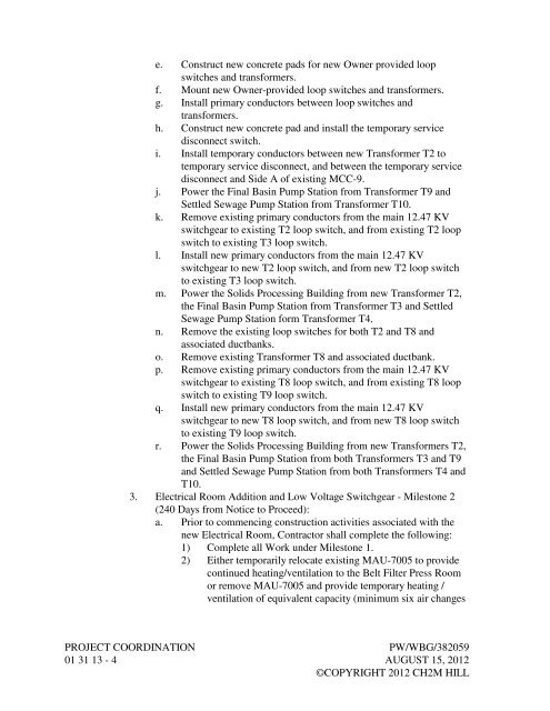
- Page 30 and 31: per hour). Heating shall be provide
- Page 32 and 33: d. Install Belt Filter Press No. 3
- Page 34 and 35: 1. Roles and responsibilities of th
- Page 36 and 37: 4. In event of discrepancy in data
- Page 38 and 39: SECTION 01 31 19PROJECT MEETINGSPAR
- Page 40: 1.08 FACILITY STARTUP MEETINGSA. Sc
- Page 43 and 44: 10. Major structural, mechanical, e
- Page 45 and 46: 4. Identify each activity with a un
- Page 47 and 48: 1.07 SCHEDULE ACCEPTANCEA. Engineer
- Page 50 and 51: SECTION 01 33 00SUBMITTAL PROCEDURE
- Page 52 and 53: a. Contractor’s review stamp; com
- Page 54 and 55: . Distribution:1) One copy furnishe
- Page 56 and 57: K. Special Guarantee: Supplier’s
- Page 58 and 59: SECTION 01 42 13ABBREVIATIONS AND A
- Page 60 and 61: 40. CRSI Concrete Reinforcing Steel
- Page 62: 117. TCA Tile Council of North Amer
- Page 65 and 66: C. Schedule manufacturer’ service
- Page 67 and 68: 1. Title and objectives.2. Recommen
- Page 70: OWNERMANUFACTURER’S CERTIFICATE O
- Page 73 and 74: C. The presence or absence of a qua
- Page 75 and 76: 1. Preparatory Phase:a. Notify Owne
- Page 77 and 78: B. Content:another interim plan con
- Page 79 and 80:
are in compliance with the Contract
- Page 82 and 83:
SECTION 01 45 33SPECIAL INSPECTION
- Page 84 and 85:
E. Professional Observation:1. Does
- Page 86 and 87:
2. Laboratory and field test report
- Page 88 and 89:
SECTION 01 50 00TEMPORARY FACILITIE
- Page 90 and 91:
E. Floor Space: Minimum 150 square
- Page 92 and 93:
3.02 TEMPORARY UTILITIESA. Power:1.
- Page 94 and 95:
8. Notify property owners and utili
- Page 96 and 97:
2. Prior to commencing excavation a
- Page 98 and 99:
SECTION 01 57 13TEMPORARY EROSION A
- Page 100 and 101:
Physical PropertyGrab Tensile Stren
- Page 102 and 103:
3.03 SEEDINGA. Schedules:1. Perform
- Page 104 and 105:
SECTION 01 61 00COMMON PRODUCT REQU
- Page 106 and 107:
C. Unload products in accordance wi
- Page 108 and 109:
I. Authority Having Jurisdiction (A
- Page 110:
D. Repaint painted surfaces that ar
- Page 113 and 114:
C. Damaged or incomplete products t
- Page 115 and 116:
3.02 FIELD FINISHINGA. Products wil
- Page 117 and 118:
esult in a deferral by Engineer to
- Page 119 and 120:
3.02 FINAL CLEANINGA. At completion
- Page 121 and 122:
B. Instructional Manual Format:1. B
- Page 123 and 124:
h. Where applicable, identify insta
- Page 125 and 126:
c. Use only 8-1/2-inch by 11-inch s
- Page 128 and 129:
Equipment RecordPage 1 of 2Equipmen
- Page 130 and 131:
SECTION 01 91 14EQUIPMENT TESTING A
- Page 132 and 133:
C. Provide temporary valves, gauges
- Page 134 and 135:
5. Unless otherwise indicated, furn
- Page 136:
UNIT PROCESS STARTUP FORMOWNER:PROJ
- Page 140 and 141:
SECTION 02 41 00DEMOLITIONPART 1GEN
- Page 142 and 143:
1.06 SEQUENCING AND SCHEDULINGA. Th
- Page 144 and 145:
3. Patching shall be as specified a
- Page 146 and 147:
4. Ensure that structural elements
- Page 148:
3. Products, equipment and applianc
- Page 151 and 152:
1.02 DEFINITIONSp. C1583/C1583M, St
- Page 153 and 154:
B. Demonstration Mockup for Hand-Ap
- Page 155 and 156:
2.02 SYSTEM D—SITE-MIXED PORTLAND
- Page 157 and 158:
C. Do not use power-driven jackhamm
- Page 159 and 160:
D. Apply scrub coat of mortar worke
- Page 161 and 162:
3.08 MORTAR REPAIR FAILED TESTA. Re
- Page 163 and 164:
1.02 DEFINITIONSp. C1012/C1012M, St
- Page 165 and 166:
B. Pre-repair Conference:1. Require
- Page 167 and 168:
F. Splitting Tensile Strength, ASTM
- Page 169 and 170:
2.06 WATERF. Abrasion Resistance De
- Page 171 and 172:
2.10 EVAPORATION RETARDANTA. As spe
- Page 173 and 174:
M. Overlays:1. Square cut edges to
- Page 175 and 176:
3. Liquid-membrane curing compounds
- Page 177 and 178:
3.10 CLEANINGA. Remove excess repai
- Page 179 and 180:
1.04 QUALIFICATIONSA. Formwork Desi
- Page 181 and 182:
3. Inspect form surfaces prior to i
- Page 184 and 185:
SECTION 03 15 00CONCRETE JOINTS AND
- Page 186 and 187:
G. Thickness: Constant from bulb ed
- Page 188 and 189:
2.07 POURABLE JOINT FILLERSA. Fille
- Page 190 and 191:
3.03 INSTALLATION OF WATERSTOPSA. G
- Page 192 and 193:
B. Bituminous Type Premolded Joint
- Page 194 and 195:
SECTION 03 21 00REINFORCING STEELPA
- Page 196 and 197:
B. Mechanical Splices and Connectio
- Page 198 and 199:
3. Welded Splices: Accomplish by fu
- Page 200 and 201:
SECTION 03 30 00CAST-IN-PLACE CONCR
- Page 202 and 203:
B. Contractor’s Licensed Design E
- Page 204 and 205:
h. Procedures for measuring and rec
- Page 206 and 207:
d. Slump and placement time to main
- Page 208 and 209:
2.02 ANCILLARY MATERIALSA. Bonding
- Page 210 and 211:
Sieve Sizes2.04 CONCRETE MIXINGComb
- Page 212 and 213:
D. Conveyor Belts and Chutes:1. Des
- Page 214 and 215:
K. Cold Weather Placement:1. Unless
- Page 216 and 217:
3.04 REPAIRING CONCRETEA. General:1
- Page 218 and 219:
B. Type S-1 (Steel Troweled Finish)
- Page 220 and 221:
3.08 BEAM AND COLUMN FINISHESA. Typ
- Page 222 and 223:
2. These specimens shall be in addi
- Page 224 and 225:
AreaWater-holding tanks, channels,
- Page 226 and 227:
CONCRETE MIX DESIGN, CLASS 5000F3S1
- Page 228:
7. Unless otherwise permitted, mini
- Page 231 and 232:
Nominal Maximum Aggregate Sizein.
- Page 233 and 234:
D. Refer to PART 1 through PART 3 o
- Page 235 and 236:
Nominal Maximum AggregateSizein.
- Page 237 and 238:
4. Limit supplementary cementitious
- Page 239 and 240:
materials providing sulfate resista
- Page 241 and 242:
B. Preinstallation Training: Manufa
- Page 243 and 244:
C. Epoxy Joint Filler:1. Allow 90 d
- Page 245 and 246:
PART 2PRODUCTS2.01 MATERIALSA. Wate
- Page 248 and 249:
SECTION 03 40 00PRECAST CONCRETEPAR
- Page 250 and 251:
C. Mockup Panels for Architectural
- Page 252 and 253:
2.03 DESIGN REQUIREMENTSA. Structur
- Page 254 and 255:
E. Lifting and Setting Panels in Po
- Page 256 and 257:
SECTION 03 62 00NONSHRINK GROUTINGP
- Page 258 and 259:
ApplicationMachine bases 25 hp orle
- Page 260 and 261:
PART 3EXECUTION3.01 NONSHRINK GROUT
- Page 262 and 263:
SUPPLEMENT 1(Test Lab Name)(Address
- Page 264:
6. Perform final observation at 24
- Page 267 and 268:
1.04 QUALITY ASSURANCEA. Qualificat
- Page 269 and 270:
3.02 FIELD QUALITY CONTROLA. Specia
- Page 271 and 272:
c. Cast stone trim Samples not less
- Page 273 and 274:
2.03 MORTAR AND GROUT MATERIALSA. M
- Page 275 and 276:
2.07 MASONRY ACCESSORIES AND ANCILL
- Page 277 and 278:
2.09 GROUT PREPARATIONA. Mix grout
- Page 279 and 280:
G. Masonry Control Joints:1. Provid
- Page 281 and 282:
acid, remove stains with fiber brus
- Page 284 and 285:
SECTION 04 22 00CONCRETE UNIT MASON
- Page 286 and 287:
5. Demonstrate ability to keep insu
- Page 288 and 289:
C. Aggregates:1. Mortar: ASTM C144,
- Page 290 and 291:
3.02 PREPARATIONA. Prepare surface
- Page 292 and 293:
4. As units are laid, remove excess
- Page 294 and 295:
6. Vertical Reinforcement:a. First
- Page 296 and 297:
24 hours, and for additional time a
- Page 298 and 299:
SECTION 05 05 23WELDINGPART 1GENERA
- Page 300 and 301:
1.04 QUALIFICATIONSA. WPSs: In acco
- Page 302:
6. Supervise nondestructive testing
- Page 306 and 307:
SECTION 05 50 00METAL FABRICATIONSP
- Page 308 and 309:
ff.gg.hh.ii.jj.kk.ll.1.02 DEFINITIO
- Page 310 and 311:
B. Package stainless steel items in
- Page 312 and 313:
B. Anchor Bolt Sleeves:1. Plastic:a
- Page 314 and 315:
2.08 U-CHANNEL CONCRETE INSERTSA. R
- Page 316 and 317:
2.12 SIDEWALK DOORSA. Load Capacity
- Page 318 and 319:
2.14 HATCH SAFETY NETA. General:1.
- Page 320 and 321:
B. Components and Accessories:1. Fo
- Page 322 and 323:
E. Galvanizing:1. Fabricate steel t
- Page 324 and 325:
C. Minimum Bolt Size: 1/2-inch diam
- Page 326 and 327:
3.08 ELECTROLYTIC PROTECTIONA. Alum
- Page 328 and 329:
Service Useand Location Product Rem
- Page 330 and 331:
SECTION 05 52 00METAL RAILINGSPART
- Page 332 and 333:
c. Deflection Criteria: In accordan
- Page 334 and 335:
C. Rails, Posts, and Formed Elbows:
- Page 336 and 337:
e. Formed Aluminum Wall Flange:1) M
- Page 338 and 339:
PART 3EXECUTION3.01 GENERALA. Provi
- Page 340:
1. Treatment of Field Welds for Gal
- Page 343 and 344:
B. Informational Submittals:1. Spec
- Page 345 and 346:
2.05 FABRICATION4. Manufacturers an
- Page 348 and 349:
SECTION 06 10 00ROUGH CARPENTRYPART
- Page 350 and 351:
D. Protect fire-retardant materials
- Page 352 and 353:
c. Wood framing members less than 1
- Page 354:
B. Use FR-S rated wood on interior
- Page 357 and 358:
B. Weather: Clear with no precipita
- Page 359 and 360:
3.05 PROTECTIONA. Protect adjacent
- Page 361 and 362:
PART 2PRODUCTS2.01 BATT INSULATION
- Page 364 and 365:
SECTION 07 52 16SBS-MODIFIED BITUMI
- Page 366 and 367:
C. Preroofing Conference:1. Attende
- Page 368 and 369:
B. Membrane and Flashing Materials:
- Page 370 and 371:
C. Tapered Board System:1. Factory
- Page 372:
3.03 FIELD QUALITY CONTROLA. Concre
- Page 375 and 376:
C. Wind Uplift Pressure: Determine
- Page 377 and 378:
2.02 REGLETS AND COUNTERFLASHINGA.
- Page 379 and 380:
2.06 FABRICATION OF FLASHINGA. Fiel
- Page 381 and 382:
B. Verify nailing strips and blocki
- Page 384 and 385:
SECTION 07 70 01ROOF SPECIALTIES AN
- Page 386 and 387:
C. Manufacturers and Products:2.05
- Page 388:
2. Use appropriate pipe curb assemb
- Page 391 and 392:
1.05 SPECIAL GUARANTEEA. Product: F
- Page 393 and 394:
H. Type 6—One-Part Polyurethane,
- Page 395 and 396:
1. Mask adjacent surfaces where nec
- Page 397 and 398:
Joint LocationsSealant Type(s)Other
- Page 400:
DOOR AND HARDWARE SCHEDULEABBREVIAT
- Page 405 and 406:
C. Kawneer.D. Special Lite, Inc.2.0
- Page 408 and 409:
SECTION 08 33 23OVERHEAD COILING DO
- Page 410 and 411:
D. Surface Burning Characteristics,
- Page 412:
C. Complete wiring from disconnect
- Page 415 and 416:
1.03 SUBMITTALSA. Action Submittals
- Page 417 and 418:
2.03 FINISHJ. Isolation Tape:1. Man
- Page 419 and 420:
3.04 MANUFACTURER’S SERVICESA. Pr
- Page 421 and 422:
1.03 QUALITY ASSURANCEA. Qualificat
- Page 423 and 424:
6. Manufacturers and Products:a. Co
- Page 425 and 426:
2.09 STOPS AND HOLDERSA. BHMA A156.
- Page 427 and 428:
PART 3EXECUTION3.01 INSTALLATIONA.
- Page 430 and 431:
SECTION 08 80 00GLAZINGPART 1GENERA
- Page 432 and 433:
. Glass: Provide structural, physic
- Page 434 and 435:
3. Conforming to CPSC 16 CFR 1201 C
- Page 436 and 437:
B. Spacer Shims: Elastomeric materi
- Page 438:
B. Replacements and Repairs: Prior
- Page 441 and 442:
B. Informational Submittals:1. Fact
- Page 443 and 444:
C. Install insulated blank-off pane
- Page 446:
SECTION 09 06 00SCHEDULES FOR FINIS
- Page 449 and 450:
Space Floor Base Typical Wall Other
- Page 451 and 452:
1.02 DEFINITIONSA. Terms used in th
- Page 453 and 454:
B. Storage:1. Store products in a p
- Page 455 and 456:
ProductEpoxy, High SolidsPolyuretha
- Page 457 and 458:
3. Where the specified degree of su
- Page 459 and 460:
. Cleaning Methods: Steam, open fla
- Page 461 and 462:
4. Apply one spot coat of specified
- Page 463 and 464:
6. Coat units or surfaces to be bol
- Page 465 and 466:
1. Use on the following items or ar
- Page 467 and 468:
3.09 COLORSA. Match existing, unles
- Page 469 and 470:
3. Apply finish coats, including to
- Page 472:
PAINT PRODUCT DATA SHEETComplete an
- Page 475 and 476:
D. Finish:1. Border Face and Edge,
- Page 477 and 478:
F. Exit Signs (Type G):1. Material:
- Page 479 and 480:
PART 3EXECUTION3.01 INSTALLATION—
- Page 481 and 482:
MarkMaterialH-18 Sulfuric Acid(12.7
- Page 484 and 485:
SIGN SCHEDULESignSize Mounting Lett
- Page 486:
SIGN SCHEDULESignSize Mounting Lett
- Page 489 and 490:
1.04 ENVIRONMENTAL REQUIREMENTSA. S
- Page 492:
SECTION 22 10 01.02POLYVINYL CHLORI
- Page 495 and 496:
SECTION 22 10 01.08POLYETHYLENE (PE
- Page 497 and 498:
B. Drainage Products:1. General:a.
- Page 499 and 500:
12. WCO, Wall Cleanout:a. Material:
- Page 502 and 503:
SECTION 23 05 93TESTING, ADJUSTING,
- Page 504 and 505:
B. General:1. When adjustments are
- Page 506:
B. Balancing Log Report Requirement
- Page 509 and 510:
D. Smoke Safety Control:1. Locate d
- Page 511 and 512:
2. Service:a. Process Fluid: Air, u
- Page 513 and 514:
k. A1008/A1008M, Standard Specifica
- Page 515 and 516:
1.04 QUALITY ASSURANCE5) Hangers an
- Page 517 and 518:
4. For ductwork that is required to
- Page 519 and 520:
B. Elbows:1. Fit square-turn elbows
- Page 521 and 522:
2.09 DUCTWORK HANGERS AND SUPPORTSA
- Page 523 and 524:
. Size to allow insertion of pitot
- Page 525 and 526:
2. Determine location of spin-in af
- Page 527 and 528:
B. Manual Dampers:1. Provide balanc
- Page 530 and 531:
SECTION 23 31 16.16THERMOSET FIBERG
- Page 532 and 533:
1.04 DELIVERY, STORAGE, AND HANDLIN
- Page 534 and 535:
C. Keep use of flanges to a minimum
- Page 536 and 537:
. Blades: Fiberglass reinforced pla
- Page 538 and 539:
SECTION 23 37 00AIR OUTLETS AND INL
- Page 540 and 541:
SECTION 23 77 00AIR HANDLING UNITSP
- Page 542 and 543:
1.03 SUBMITTALS14. IEC: Internation
- Page 544 and 545:
1.04 QUALITY ASSURANCEA. Fans: Lice
- Page 546 and 547:
2. Guard faces of expanded metal ha
- Page 548 and 549:
C. Unit Base:b. Sized and located t
- Page 550 and 551:
3) Selected for average life (ABMA
- Page 552 and 553:
2. Media Schedule:a. Main Filter:1)
- Page 554 and 555:
2) Sized and located to provide eas
- Page 556 and 557:
2.10 SOURCE QUALITY CONTROLA. Facto
- Page 558 and 559:
3.02 FIELD QUALITY CONTROLA. Functi
- Page 560 and 561:
AIR HANDLING UNITSEQUIPMENT ID NUMB
- Page 562 and 563:
SECTION 23 81 00UNITARY AIR-CONDITI
- Page 564 and 565:
1.04 QUALITY ASSURANCEA. Heating an
- Page 566 and 567:
D. Refrigeration Components:1. Refr
- Page 568 and 569:
4. Disconnects: Factory installed n
- Page 570 and 571:
C. Anchor Bolts: Type 316 stainless
- Page 572:
3.04 MANUFACTURER’S SERVICESA. Pr