- Page 1 and 2:
CONTRACT DOCUMENTS ANDSPECIFICATION
- Page 4 and 5:
TABLE OF CONTENTSPagesTECHNICAL SPE
- Page 6 and 7:
PagesDIVISION 8—OPENINGS08 06 01
- Page 8 and 9:
PagesDIVISION 27 (NOT USED)DIVISION
- Page 10:
DIVISION 43—PROCESS GAS AND LIQUI
- Page 14:
SECTION 01 11 00SUMMARY OF WORKPART
- Page 17 and 18:
5. Estimated adjustment in price cl
- Page 19 and 20:
2. Change Order constitutes full mu
- Page 21 and 22:
1.06 FIELD ORDER75 percent of the a
- Page 23 and 24:
B. Base estimated progress payments
- Page 26 and 27:
SECTION 01 31 13PROJECT COORDINATIO
- Page 28 and 29:
E. Construct Work in the following
- Page 30 and 31:
per hour). Heating shall be provide
- Page 32 and 33:
d. Install Belt Filter Press No. 3
- Page 34 and 35:
1. Roles and responsibilities of th
- Page 36 and 37:
4. In event of discrepancy in data
- Page 38 and 39:
SECTION 01 31 19PROJECT MEETINGSPAR
- Page 40:
1.08 FACILITY STARTUP MEETINGSA. Sc
- Page 43 and 44:
10. Major structural, mechanical, e
- Page 45 and 46:
4. Identify each activity with a un
- Page 47 and 48:
1.07 SCHEDULE ACCEPTANCEA. Engineer
- Page 50 and 51:
SECTION 01 33 00SUBMITTAL PROCEDURE
- Page 52 and 53:
a. Contractor’s review stamp; com
- Page 54 and 55:
. Distribution:1) One copy furnishe
- Page 56 and 57:
K. Special Guarantee: Supplier’s
- Page 58 and 59:
SECTION 01 42 13ABBREVIATIONS AND A
- Page 60 and 61:
40. CRSI Concrete Reinforcing Steel
- Page 62:
117. TCA Tile Council of North Amer
- Page 65 and 66:
C. Schedule manufacturer’ service
- Page 67 and 68:
1. Title and objectives.2. Recommen
- Page 70:
OWNERMANUFACTURER’S CERTIFICATE O
- Page 73 and 74:
C. The presence or absence of a qua
- Page 75 and 76:
1. Preparatory Phase:a. Notify Owne
- Page 77 and 78:
B. Content:another interim plan con
- Page 79 and 80:
are in compliance with the Contract
- Page 82 and 83:
SECTION 01 45 33SPECIAL INSPECTION
- Page 84 and 85:
E. Professional Observation:1. Does
- Page 86 and 87:
2. Laboratory and field test report
- Page 88 and 89:
SECTION 01 50 00TEMPORARY FACILITIE
- Page 90 and 91:
E. Floor Space: Minimum 150 square
- Page 92 and 93:
3.02 TEMPORARY UTILITIESA. Power:1.
- Page 94 and 95:
8. Notify property owners and utili
- Page 96 and 97:
2. Prior to commencing excavation a
- Page 98 and 99:
SECTION 01 57 13TEMPORARY EROSION A
- Page 100 and 101:
Physical PropertyGrab Tensile Stren
- Page 102 and 103:
3.03 SEEDINGA. Schedules:1. Perform
- Page 104 and 105:
SECTION 01 61 00COMMON PRODUCT REQU
- Page 106 and 107:
C. Unload products in accordance wi
- Page 108 and 109:
I. Authority Having Jurisdiction (A
- Page 110:
D. Repaint painted surfaces that ar
- Page 113 and 114:
C. Damaged or incomplete products t
- Page 115 and 116:
3.02 FIELD FINISHINGA. Products wil
- Page 117 and 118:
esult in a deferral by Engineer to
- Page 119 and 120:
3.02 FINAL CLEANINGA. At completion
- Page 121 and 122:
B. Instructional Manual Format:1. B
- Page 123 and 124:
h. Where applicable, identify insta
- Page 125 and 126:
c. Use only 8-1/2-inch by 11-inch s
- Page 128 and 129:
Equipment RecordPage 1 of 2Equipmen
- Page 130 and 131:
SECTION 01 91 14EQUIPMENT TESTING A
- Page 132 and 133:
C. Provide temporary valves, gauges
- Page 134 and 135:
5. Unless otherwise indicated, furn
- Page 136:
UNIT PROCESS STARTUP FORMOWNER:PROJ
- Page 140 and 141:
SECTION 02 41 00DEMOLITIONPART 1GEN
- Page 142 and 143:
1.06 SEQUENCING AND SCHEDULINGA. Th
- Page 144 and 145:
3. Patching shall be as specified a
- Page 146 and 147:
4. Ensure that structural elements
- Page 148:
3. Products, equipment and applianc
- Page 151 and 152:
1.02 DEFINITIONSp. C1583/C1583M, St
- Page 153 and 154:
B. Demonstration Mockup for Hand-Ap
- Page 155 and 156:
2.02 SYSTEM D—SITE-MIXED PORTLAND
- Page 157 and 158:
C. Do not use power-driven jackhamm
- Page 159 and 160:
D. Apply scrub coat of mortar worke
- Page 161 and 162:
3.08 MORTAR REPAIR FAILED TESTA. Re
- Page 163 and 164:
1.02 DEFINITIONSp. C1012/C1012M, St
- Page 165 and 166:
B. Pre-repair Conference:1. Require
- Page 167 and 168:
F. Splitting Tensile Strength, ASTM
- Page 169 and 170:
2.06 WATERF. Abrasion Resistance De
- Page 171 and 172:
2.10 EVAPORATION RETARDANTA. As spe
- Page 173 and 174:
M. Overlays:1. Square cut edges to
- Page 175 and 176:
3. Liquid-membrane curing compounds
- Page 177 and 178:
3.10 CLEANINGA. Remove excess repai
- Page 179 and 180:
1.04 QUALIFICATIONSA. Formwork Desi
- Page 181 and 182:
3. Inspect form surfaces prior to i
- Page 184 and 185:
SECTION 03 15 00CONCRETE JOINTS AND
- Page 186 and 187:
G. Thickness: Constant from bulb ed
- Page 188 and 189:
2.07 POURABLE JOINT FILLERSA. Fille
- Page 190 and 191:
3.03 INSTALLATION OF WATERSTOPSA. G
- Page 192 and 193:
B. Bituminous Type Premolded Joint
- Page 194 and 195:
SECTION 03 21 00REINFORCING STEELPA
- Page 196 and 197:
B. Mechanical Splices and Connectio
- Page 198 and 199:
3. Welded Splices: Accomplish by fu
- Page 200 and 201:
SECTION 03 30 00CAST-IN-PLACE CONCR
- Page 202 and 203:
B. Contractor’s Licensed Design E
- Page 204 and 205:
h. Procedures for measuring and rec
- Page 206 and 207:
d. Slump and placement time to main
- Page 208 and 209:
2.02 ANCILLARY MATERIALSA. Bonding
- Page 210 and 211:
Sieve Sizes2.04 CONCRETE MIXINGComb
- Page 212 and 213:
D. Conveyor Belts and Chutes:1. Des
- Page 214 and 215:
K. Cold Weather Placement:1. Unless
- Page 216 and 217:
3.04 REPAIRING CONCRETEA. General:1
- Page 218 and 219:
B. Type S-1 (Steel Troweled Finish)
- Page 220 and 221:
3.08 BEAM AND COLUMN FINISHESA. Typ
- Page 222 and 223:
2. These specimens shall be in addi
- Page 224 and 225:
AreaWater-holding tanks, channels,
- Page 226 and 227:
CONCRETE MIX DESIGN, CLASS 5000F3S1
- Page 228:
7. Unless otherwise permitted, mini
- Page 231 and 232:
Nominal Maximum Aggregate Sizein.
- Page 233 and 234:
D. Refer to PART 1 through PART 3 o
- Page 235 and 236:
Nominal Maximum AggregateSizein.
- Page 237 and 238:
4. Limit supplementary cementitious
- Page 239 and 240:
materials providing sulfate resista
- Page 241 and 242:
B. Preinstallation Training: Manufa
- Page 243 and 244:
C. Epoxy Joint Filler:1. Allow 90 d
- Page 245 and 246:
PART 2PRODUCTS2.01 MATERIALSA. Wate
- Page 248 and 249:
SECTION 03 40 00PRECAST CONCRETEPAR
- Page 250 and 251:
C. Mockup Panels for Architectural
- Page 252 and 253: 2.03 DESIGN REQUIREMENTSA. Structur
- Page 254 and 255: E. Lifting and Setting Panels in Po
- Page 256 and 257: SECTION 03 62 00NONSHRINK GROUTINGP
- Page 258 and 259: ApplicationMachine bases 25 hp orle
- Page 260 and 261: PART 3EXECUTION3.01 NONSHRINK GROUT
- Page 262 and 263: SUPPLEMENT 1(Test Lab Name)(Address
- Page 264: 6. Perform final observation at 24
- Page 267 and 268: 1.04 QUALITY ASSURANCEA. Qualificat
- Page 269 and 270: 3.02 FIELD QUALITY CONTROLA. Specia
- Page 271 and 272: c. Cast stone trim Samples not less
- Page 273 and 274: 2.03 MORTAR AND GROUT MATERIALSA. M
- Page 275 and 276: 2.07 MASONRY ACCESSORIES AND ANCILL
- Page 277 and 278: 2.09 GROUT PREPARATIONA. Mix grout
- Page 279 and 280: G. Masonry Control Joints:1. Provid
- Page 281 and 282: acid, remove stains with fiber brus
- Page 284 and 285: SECTION 04 22 00CONCRETE UNIT MASON
- Page 286 and 287: 5. Demonstrate ability to keep insu
- Page 288 and 289: C. Aggregates:1. Mortar: ASTM C144,
- Page 290 and 291: 3.02 PREPARATIONA. Prepare surface
- Page 292 and 293: 4. As units are laid, remove excess
- Page 294 and 295: 6. Vertical Reinforcement:a. First
- Page 296 and 297: 24 hours, and for additional time a
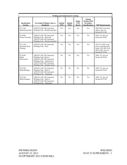
- Page 298 and 299: SECTION 05 05 23WELDINGPART 1GENERA
- Page 300 and 301: 1.04 QUALIFICATIONSA. WPSs: In acco
- Page 302: 6. Supervise nondestructive testing
- Page 307 and 308: i. A194/A194M, Specification for Ca
- Page 309 and 310: E. Submerged: Location at or below
- Page 311 and 312: ItemSteel Bolts and Nuts:Carbon Ste
- Page 313 and 314: . Store adhesive cartridges on pall
- Page 315 and 316: 2.10 FLOOR PLATEA. Material:1. Alum
- Page 317 and 318: 2.13 FLOOR HATCHESA. Load Capacity:
- Page 319 and 320: 5. Fabricate to longest length as p
- Page 321 and 322: 2.20 FABRICATIONA. General:1. Finis
- Page 323 and 324: PART 3EXECUTION3.01 INSTALLATION OF
- Page 325 and 326: 5. Do not exceed maximum torque as
- Page 327 and 328: 3.10 MANUFACTURER’S SERVICESA. Ad
- Page 329 and 330: Service Useand Location Product Rem
- Page 331 and 332: c. Design Data: Calculations or tes
- Page 333 and 334: PART 2PRODUCTS2.01 DESIGN PERFORMAN
- Page 335 and 336: e. Base Connection:1) Manufacturers
- Page 337 and 338: B. Bolts and Nuts for Bolting Handr
- Page 339 and 340: D. Setting Posts:1. Surface Mounted
- Page 342 and 343: SECTION 05 53 00METAL GRATINGSPART
- Page 344 and 345: 5. Bearing Bars, Cross Bars and Ban
- Page 346: 2. Coordinate dimensions and fabric
- Page 349 and 350: 1.02 SUBMITTALSA. Action Submittals
- Page 351 and 352: 2.03 CONSTRUCTION PANELSA. Plywood:
- Page 353 and 354:
PART 3EXECUTION3.01 EXAMINATIONA. V
- Page 356 and 357:
SECTION 07 19 00WATER REPELLENTSPAR
- Page 358 and 359:
PART 3EXECUTION3.01 EXAMINATION AND
- Page 360 and 361:
SECTION 07 21 00THERMAL INSULATIONP
- Page 362:
3.02 RIGID INSULATIONA. Install in
- Page 365 and 366:
1.02 SUBMITTALSb. HH-I/2, (Basic; A
- Page 367 and 368:
1.07 SPECIAL GUARANTEEA. Product: F
- Page 369 and 370:
2. Flashing sheet combining SBS pol
- Page 371 and 372:
B. Bitumen:1. Maintain kettle tempe
- Page 374 and 375:
SECTION 07 62 00SHEET METAL FLASHIN
- Page 376 and 377:
C. Carefully handle to avoid damage
- Page 378 and 379:
C. Finish: Factory finished with an
- Page 380 and 381:
K. At exposed ends of counterflashi
- Page 382:
3.03 FINISHA. Exposed Surfaces of F
- Page 385 and 386:
D. Manufacturers and Products:1. Pa
- Page 387 and 388:
2.09 ROOF DRAINSA. Molded plastic d
- Page 390 and 391:
SECTION 07 92 00JOINT SEALANTSPART
- Page 392 and 393:
3. Manufacturers and Products:a. BA
- Page 394 and 395:
B. Joint Cleaner: Noncorrosive and
- Page 396 and 397:
C. Apply joint sealant manufacturer
- Page 398:
SECTION 08 06 01DOOR AND HARDWARE S
- Page 404 and 405:
SECTION 08 11 16ALUMINUM DOORS AND
- Page 406:
PART 3EXECUTION3.01 INSTALLATIONA.
- Page 409 and 410:
B. Informational Submittals:1. Thir
- Page 411 and 412:
2.04 FINISHES4. Motor Rating: Minim
- Page 414 and 415:
SECTION 08 41 13ALUMINUM-FRAMED ENT
- Page 416 and 417:
PART 2PRODUCTS2.01 MANUFACTURERSA.
- Page 418 and 419:
3.02 INSTALLATIONA. In accordance w
- Page 420 and 421:
SECTION 08 71 00DOOR HARDWAREPART 1
- Page 422 and 423:
Door HeightUp to 5'-0”5'-1” to
- Page 424 and 425:
2.07 EXIT DEVICESA. BHMA A156.3.B.
- Page 426 and 427:
No. Type Description Pemko ReeseT2
- Page 428:
3.03 MANUFACTURER’S SERVICESA. De
- Page 431 and 432:
1.02 SUBMITTALSp. E1300, Standard P
- Page 433 and 434:
B. Handling:1. Stack individual lit
- Page 435 and 436:
1. Silicone Glazing Sealant: ASTM C
- Page 437 and 438:
B. Exterior Dry Method (Gasket Glaz
- Page 440 and 441:
SECTION 08 90 00LOUVERSPART 1GENERA
- Page 442 and 443:
2.03 ACCESSORIESA. Anchors and Fast
- Page 444:
LOUVER SCHEDULELOUVER TYPES: ABBREV
- Page 448 and 449:
INTERIOR FINISH SCHEDULEABBREVIATIO
- Page 450 and 451:
SECTION 09 90 00PAINTING AND COATIN
- Page 452 and 453:
3. Factory Applied Coatings: Manufa
- Page 454 and 455:
2.03 PAINT MATERIALSA. General:1. M
- Page 456 and 457:
d. Prior to blast cleaning, grind s
- Page 458 and 459:
more than 5 percent of each unit ar
- Page 460 and 461:
4. Brush-off blast clean to remove
- Page 462 and 463:
c. Acid will react vigorously for a
- Page 464 and 465:
4. Visually inspect concrete, mason
- Page 466 and 467:
G. System No. 25 Exposed PVC:Surfac
- Page 468 and 469:
pinholes, holidays, and discontinui
- Page 470:
PAINT SYSTEM DATA SHEETComplete thi
- Page 474 and 475:
SECTION 10 14 00SIGNAGEPART 1GENERA
- Page 476 and 477:
2.04 SIGNSC. Manufacturers and Prod
- Page 478 and 479:
6. Manufacturers and Products:a. Br
- Page 480 and 481:
MarkMaterialH-3 CalciumHydroxide (9
- Page 482:
3.07 SUPPLEMENTS2. Operating Proced
- Page 485 and 486:
SIGN SCHEDULESignSize Mounting Lett
- Page 488 and 489:
SECTION 10 44 00PORTABLE FIRE AND S
- Page 490:
PART 3EXECUTION3.01 INSTALLATIONA.
- Page 494 and 495:
SECTION 22 10 01.08POLYETHYLENE (PE
- Page 496 and 497:
SECTION 22 40 00PLUMBING FIXTURESPA
- Page 498 and 499:
4. FD-2, Floor Drain (Unfinished Ar
- Page 500:
D. Adjust water flows in domestic w
- Page 503 and 504:
4. Have a proven record of at least
- Page 505 and 506:
4. Adjust outside air dampers, retu
- Page 508 and 509:
SECTION 23 09 00.01HVAC CONTROLS SE
- Page 510 and 511:
SECTION 23 09 13HVAC CONTROLS, FIEL
- Page 512 and 513:
SECTION 23 31 13METAL DUCTS AND ACC
- Page 514 and 515:
1.02 DEFINITIONSd. Fire, Smoke, and
- Page 516 and 517:
E. Changes or alterations to layout
- Page 518 and 519:
D. Water-Based Sealants:1. Listed b
- Page 520 and 521:
2. Provide fasteners that do not da
- Page 522 and 523:
2.10 MANUAL DAMPERSA. Butterfly Man
- Page 524 and 525:
C. Penetrations:1. Provide duct sle
- Page 526 and 527:
D. Support horizontal ducts within
- Page 528:
3.09 BALANCING OF AIR SYSTEMSA. Per
- Page 531 and 532:
e. Drawings showing layout, support
- Page 533 and 534:
B. Reinforcement:1. Veil: Chemical
- Page 535 and 536:
3. Support Spacing:a. 24 Inch Diame
- Page 537 and 538:
6. Anti-seize thread compound shall
- Page 539 and 540:
4. 1-inch minimum flat rectangular
- Page 541 and 542:
1.02 DEFINITIONS6. CSA America (CSA
- Page 543 and 544:
d) Static pressure, capacity, horse
- Page 545 and 546:
PART 2PRODUCTS2.01 EQUIPMENT SCHEDU
- Page 547 and 548:
2. Panel Arrangement: Panels mechan
- Page 549 and 550:
5) Base:a) All-welded heavy-gauge m
- Page 551 and 552:
d. Adequately sized access door(s)
- Page 553 and 554:
H. Control Dampers:1. Internally mo
- Page 555 and 556:
2.08 CORROSION PROTECTIONA. General
- Page 557 and 558:
a. Belt Drive (except Vane Axial):
- Page 559 and 560:
E. Vibration Testing:3.04 CLEANING1
- Page 561 and 562:
AIR HANDLING UNITSEQUIPMENT ID NUMB
- Page 563 and 564:
1.02 DEFINITIONSA. The following is
- Page 565 and 566:
PART 2PRODUCTS2.01 GENERALA. Specif
- Page 567 and 568:
5. Low pressure bypass shall be fac
- Page 569 and 570:
C. Coating Process:1. Coil Inspecti
- Page 571 and 572:
supervise initial operation, calibr
- Page 574:
WALL MOUNT AIR CONDITIONER 23 81 00