Incompatibilities of the Shielding Theory
Incompatibilities of the Shielding Theory
Incompatibilities of the Shielding Theory

You also want an ePaper? Increase the reach of your titles
YUMPU automatically turns print PDFs into web optimized ePapers that Google loves.
<strong>Incompatibilities</strong> <strong>of</strong> <strong>the</strong> <strong>Shielding</strong><br />
<strong>Theory</strong><br />
Abstract — The paper deals with highlighting <strong>the</strong><br />
incongruities appearing both in Schelkun<strong>of</strong>f's equation<br />
as well as in <strong>the</strong> isomorphism attached to this model.<br />
These things are important because many experimental<br />
methods for determining shielding effectiveness are<br />
based on this model. It has been observed, in a large<br />
number <strong>of</strong> tests, that results do not match <strong>the</strong>ory.,<br />
especially in <strong>the</strong> area <strong>of</strong> high frequencies, where<br />
wavelength ? becomes comparable to <strong>the</strong> shield<br />
thickness d, as well as correct determination <strong>of</strong><br />
absorption and reflection loss.<br />
I. INTRODUCTION<br />
At present, <strong>the</strong>re are many analytical and computing<br />
models to solve, at least <strong>the</strong>oretically, <strong>the</strong> problem <strong>of</strong><br />
electromagnetic shi elding, meaning <strong>the</strong> determination<br />
<strong>of</strong> <strong>the</strong> influence <strong>of</strong> a shield<br />
(conductor/semiconductor, with/without magnetic<br />
properties) on electromagnetic radiation. Mainly, two<br />
have been used more <strong>of</strong>ten: Kaden model for<br />
symmetrical structures and Schelkun<strong>of</strong>f model for <strong>the</strong><br />
infinite plane shield.<br />
Schelkun<strong>of</strong>f model, <strong>the</strong> subject <strong>of</strong> this paper, is<br />
considered <strong>the</strong> most accurate from <strong>the</strong> viewpoint <strong>of</strong><br />
<strong>the</strong> initial conditions and algorithm. Based on it many<br />
testing methods have been issued, for different<br />
materials, some <strong>of</strong> <strong>the</strong>m generating civilian (ASTM)<br />
or military (MIL) standards.<br />
Recent research and tests performed in different<br />
laboratories lead, more and more, to <strong>the</strong> conclusion<br />
that even apparently correct, this model is not so<br />
interesting for applications, due to a certain number<br />
<strong>of</strong> problems:<br />
- basic incongruities derived directly from <strong>the</strong><br />
<strong>the</strong>oretical background;<br />
- limitations in practical applications;<br />
- deficiencies <strong>of</strong> Schelkun<strong>of</strong>f isomorphism.<br />
The paper aims to highlight all <strong>the</strong>se three types <strong>of</strong><br />
problems and to revise <strong>the</strong> model where possible.<br />
II. BASIC INCONGRUITIES<br />
As known, Schelkun<strong>of</strong>f model gives a general<br />
explanation for <strong>the</strong> attenuation introduced by an<br />
infinite plane shield placed in free space, illuminated<br />
on one face by an electromagnetic field (normal<br />
incidence) in Fresnel or Fraunh<strong>of</strong>er zones. The model<br />
Authors are with <strong>the</strong> Research Institute for Electrical Engineering<br />
- ICPE,Splaiul Unirii 313, Bucharest 74204, ROMANIA, phone: +40 21<br />
346 49 33, fax: +40 21 346 72 68, e-mail:mbadic@icpe.ro, mjm@icpe.ro.<br />
Mihai Badic and Mihai-Jo Marinescu<br />
is applicable from industrial frequency up to optical<br />
domain, meaning <strong>the</strong> whole range <strong>of</strong> non-ionizing<br />
radiation:<br />
R<br />
SE =A + R + B<br />
dB<br />
dB<br />
dB<br />
A = 20 log e<br />
dB 10<br />
ad<br />
dB<br />
( + Z )<br />
2<br />
Z 0 m<br />
dB=<br />
20 log<br />
(1)<br />
10<br />
4 Z 0 Z m<br />
Z m-Z<br />
0<br />
B dB=<br />
10 - e<br />
Z m+<br />
Z 0<br />
1 log 20 ⎟ ⎛ ⎞<br />
⎜<br />
⎝ ⎠<br />
2<br />
-2?d<br />
In equation (1) [1], [2], SEdB is shielding<br />
effectiveness, defined as <strong>the</strong> ratio between intensities<br />
<strong>of</strong> electric/magnetic/electromagnetic fields without<br />
respectively with shield, at normal incidence. The<br />
o<strong>the</strong>r magnitudes are:<br />
-Z0=F(µ0,e0) wave impedance in free space;<br />
-Zm=F(µ,e,s,?) wave impedance in material<br />
-?=a+jß=F(µ,e,s,?) propagation constant<br />
-d=material thickness<br />
According to <strong>the</strong> algorithm generated by <strong>the</strong> <strong>the</strong>ory<br />
given by Schelkun<strong>of</strong>f in 1943, SEdB is <strong>the</strong> sum <strong>of</strong><br />
three terms: AdB-absorption loss, RdB-reflection loss<br />
and BdB-re-reflection correction. This ma<strong>the</strong>matical<br />
formulation does not represent accurately <strong>the</strong><br />
phenomenon. Thus, <strong>the</strong> reflection rules, at normal<br />
incidence, applied on <strong>the</strong> incident surface, may be<br />
written as:<br />
WE I + WE R = WE T (for electric field) (2)<br />
WH I + WH R = WH T (for magnetic field) (3)<br />
meaning that on every boundary between<br />
environments <strong>the</strong> sum <strong>of</strong> incident and reflected waves<br />
amplitudes is equal to <strong>the</strong> transmitted wave amplitude.<br />
Also, considering now <strong>the</strong> whole configuration,<br />
following relationship must be satisfied:<br />
WE I + WE R = WE T +WE A (for electric field) (4)<br />
WH I + WH R = WH T + W H A (for magnetic field) (5)<br />
containing, obviously, <strong>the</strong> wave absorbed in shield.<br />
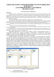
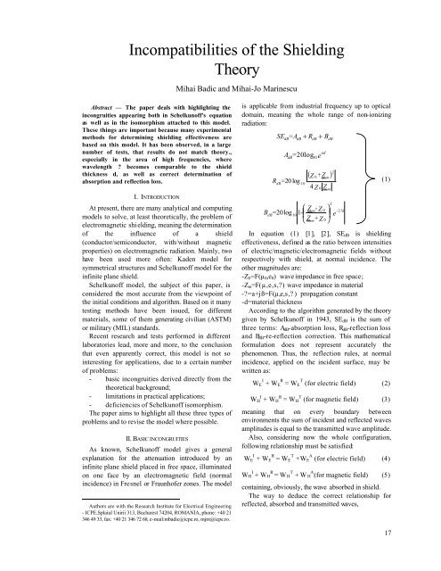
The way to deduce <strong>the</strong> correct relationship for<br />
reflected, absorbed and transmitted waves,<br />
17
considering multiple re-reflection phenomena on<br />
surfaces separating <strong>the</strong> two environments, is done as<br />
shown in Fig.1.<br />
Adding <strong>the</strong> terms representing <strong>the</strong> three phenomena<br />
in discussion, it is finally obtained:<br />
18<br />
2γd<br />
R e −1<br />
W = ± Γ 2γd<br />
2<br />
e − Γ<br />
−γd<br />
( ± Γ)(<br />
1 − e )<br />
(6)<br />
γd<br />
A<br />
e<br />
W = 1 (7)<br />
γd<br />
e m Γ<br />
2γd<br />
T<br />
−γ<br />
d e<br />
W = ( 1−<br />
Γ)<br />
e<br />
(8)<br />
2γd<br />
2<br />
e − Γ<br />
PHENOMENA :<br />
1+ΓAM<br />
e -γd<br />
ΓAM Γ MA ΓMA<br />
1+ΓMA<br />
INCIDENT WAVE<br />
1<br />
ΓAM<br />
(1+ΓAM) (1+ΓMA)ΓMA e -2γd<br />
(1+ΓAM) (1+ΓMA) Γ 3 MA e -4γd<br />
In <strong>the</strong> above equations we assumed incident wave<br />
W I ≡1, G=GAM=-GMA representing <strong>the</strong> reflection<br />
factor. The first algebraic sign is valid for <strong>the</strong><br />
electrical component and <strong>the</strong> second one for <strong>the</strong><br />
magnetic component. It can be easily observed that<br />
above equations differ from <strong>the</strong> ones obtained using<br />
<strong>the</strong> classical Schelkun<strong>of</strong>f algorithm, being identical<br />
only in <strong>the</strong> case <strong>of</strong> transmitted wave. At <strong>the</strong> same<br />
time, it can be verified that <strong>the</strong>se expressions check<br />
equations (4-5) - <strong>the</strong> laws <strong>of</strong> reflection and<br />
transmission) - unlike <strong>the</strong> expressions from <strong>the</strong><br />
Schelkun<strong>of</strong>f model used now.<br />
Equations (6-8) <strong>of</strong>fer <strong>the</strong> possibility to check<br />
experimentally <strong>the</strong> reflection and absorption<br />
phenomena for <strong>the</strong> ideal case <strong>of</strong> infinite plane shield<br />
placed in free space.<br />
1+ΓMA<br />
I AIR (A) II MATERIAL (M) III AIR (A)<br />
1+ΓAM (1+ΓAM) e -γd (1+ΓAM) (1+ΓMA) e -γd<br />
(1+ΓAM) ΓMA e -γd<br />
(1+ΓAM) ΓMA e -2γd<br />
(1+ΓAM) Γ 2 MA e -2γd<br />
(1) (2)<br />
(1+ΓAM) Γ 2 MA e -3γd (1+ΓAM) (1+ΓMA)Γ 2 MA e -3γd<br />
(1+ΓAM) Γ 3 MA e -3γd<br />
etc.<br />
d<br />
(1+ΓAM) Γ 3 MA e -4γd<br />
Fig. 1. Algorithm for determining reflection and absorption loss in plane shield - far field zone.
III. EXTENSION OF PRACTICAL APPLICATIONS<br />
Equation (1) was applied, up to present, only for<br />
conductors/semiconductors with or without magnetic<br />
properties. These considerations imply <strong>the</strong> following<br />
condition:<br />
σ ωε ⇔ Z >> Z<br />
(9)<br />
>> 0<br />
As consequence, equation (1) becomes:<br />
SE<br />
dB<br />
m<br />
⎛<br />
⎞<br />
αd Z<br />
⎜ 0<br />
−2γd ≅ 20 log<br />
⎟<br />
⎜<br />
e ⋅ 1−<br />
e<br />
(10)<br />
⎟<br />
⎝ 4 Z m ⎠<br />
Considering that for metals<br />
1 ωμσ<br />
α ≅ β = =<br />
(11)<br />
δ 2<br />
and detailing <strong>the</strong> respective modules results an<br />
expression equivalent to (10), that is [3]:<br />
⎧ d δ Z0σδ<br />
−2d δ<br />
−4d<br />
δ ⎫<br />
SEdB<br />
= 20 log⎨e<br />
⋅ ⋅ 1−<br />
2e<br />
cos2d<br />
δ + e ⎬<br />
⎩ 4 2<br />
⎭<br />
(12)<br />
Equations (10) and (12) are used currently in <strong>the</strong><br />
experimental methods for determining shielding<br />
effectiveness by means <strong>of</strong> coaxial TEM cells<br />
according to ASTM ES7-83 and ASTM D4935-89. If<br />
<strong>the</strong> shield material presents strong resonance<br />
absorption regions so that loss becomes comparable<br />
to <strong>the</strong> one characteristic to conduction, at least within<br />
certain frequency range, <strong>the</strong>n assumption s >>?e is no<br />
longer valid and <strong>the</strong>refore all <strong>the</strong> above<br />
approximations are not correct. In this case, modules<br />
from equation (1) must be detailed, implying an<br />
elementary but laborious calculation.<br />
If we accept <strong>the</strong> separation <strong>of</strong> phenomena into<br />
absorption, reflection and respectively re-reflection<br />
correction, according to classical <strong>the</strong>ory, <strong>the</strong>n <strong>the</strong><br />
complete expression <strong>of</strong> (1) becomes as follows:<br />
αd<br />
ωε<br />
A = 20 log e ; α = ωμ Δ ⋅ 0,<br />
5 − 0,<br />
5 (13)<br />
dB<br />
Δ<br />
where<br />
Δ =<br />
σ<br />
2<br />
2<br />
+ ω ε<br />
2<br />
⎡ Δ<br />
ωε 1 ωμ ⎤<br />
R = 20 log 0,<br />
25⎢377<br />
⋅ + 2 0,<br />
5 + +<br />
dB<br />
⎥ (14)<br />
⎢ ωμ<br />
⎣<br />
2 Δ 377 Δ ⎥⎦<br />
B dB<br />
2 2<br />
A + B<br />
= 20 log<br />
(15)<br />
2 ωμ ωε ωμ<br />
377 + 2 ⋅ 377 ⋅ ⋅ 0,<br />
5 + +<br />
Δ 2 Δ Δ<br />
Thus, we obtained expressions for reflection<br />
absorption and respectively re-reflection loss for <strong>the</strong><br />
most general case <strong>of</strong> conductive dielectrics, all<br />
macroscopic parameters e µ s having comparable<br />
weights. In <strong>the</strong>se equations A and B have <strong>the</strong> following<br />
expressions:<br />
2<br />
2<br />
ω με ω με −2αd<br />
ωμσ −2<br />
αd<br />
A = − e cos 2βd<br />
− e sin 2βd<br />
+<br />
Δ Δ<br />
Δ<br />
2 −2αd<br />
+ 377 ( 1 − e cos2βd<br />
) + 2 ⋅ 377<br />
ωμ<br />
⋅<br />
Δ<br />
ωε<br />
0,<br />
5 +<br />
2 Δ<br />
+<br />
+ 2 ⋅ 377 ⋅<br />
ωμ<br />
⋅<br />
Δ<br />
ωε −2αd<br />
0,<br />
5 + e cos2βd<br />
+<br />
2 Δ<br />
(16)<br />
+ 2 ⋅ 377 ⋅<br />
− 2 ⋅ 377 ⋅<br />
+ 2 ⋅377<br />
⋅<br />
+ 2 ⋅377<br />
⋅<br />
ωμ<br />
⋅<br />
Δ<br />
ωμ<br />
⋅<br />
Δ<br />
ωμ<br />
⋅<br />
Δ<br />
ωμ<br />
⋅<br />
Δ<br />
ωε<br />
0,<br />
5 − e<br />
2 Δ<br />
−2αd<br />
ωε<br />
0,<br />
5 + ⋅ e<br />
2 Δ<br />
ωε<br />
0,<br />
5 − e<br />
2 Δ<br />
ωε<br />
0,<br />
5 − e<br />
2 Δ<br />
sin 2βd<br />
ωμσ ωμσ −2αd<br />
B = − ⋅ e ⋅ cos 2βd<br />
+<br />
Δ Δ<br />
2<br />
ω με −2αd<br />
2 −2αd<br />
+ e sin 2βd<br />
+ 377 ⋅ e sin 2βd<br />
−<br />
Δ<br />
where a was given in (13) and :<br />
−2αd<br />
−2αd<br />
−2αd<br />
sin 2βd<br />
+<br />
+<br />
cos 2βd<br />
(17)<br />
ωε<br />
β = ωμ Δ ⋅ 0 , 5 + 0,<br />
5<br />
(18)<br />
Δ<br />
IV. SCHELKUNOFF ISOMORPHISM FAILURE<br />
Besides its <strong>the</strong>oretical importance, <strong>the</strong> infinite<br />
plane shield <strong>the</strong>ory has generated <strong>the</strong> respective<br />
isomorphism. Thus, it may be easily shown that<br />
equation (1) is identical to <strong>the</strong> one describing <strong>the</strong><br />
functioning <strong>of</strong> a transmission line with impedance Z0,<br />
having an insertion <strong>of</strong> a line segment with impedance<br />
Zm and length d. This way, electric field E and<br />
magnetic field H are replaced by voltage U<br />
respectively current I. To macroscopic parameters <strong>of</strong><br />
shield (e, µ, s) correspond <strong>the</strong> parameters <strong>of</strong> <strong>the</strong><br />
transmission line. <strong>Shielding</strong> effectiveness SEdB is<br />
replaced by <strong>the</strong> insertion attenuation IAdB given by <strong>the</strong><br />
Zm segment.<br />
This isomorphism has generated, in its turn, an<br />
experimental measuring method for shielding<br />
capabilities <strong>of</strong> materials. The model simulates <strong>the</strong><br />
conditions <strong>of</strong> infinite plane shield in free space by<br />
means <strong>of</strong> a washer shaped material introduced in a<br />
TEM mode coaxial cell that is practically an expanded<br />
coaxial cable. [4], [5], [6]. This system, according to<br />
<strong>the</strong> respective ASTM standards, should function up to<br />
frequency 1-1.5GHz, this being <strong>the</strong> limit<br />
characterized by occurrence <strong>of</strong> higher modes (H11,<br />
E01) in <strong>the</strong> TEM cell. The limit is determined by <strong>the</strong><br />
usual dimensions <strong>of</strong> <strong>the</strong> coaxial TEM cells.<br />
By means <strong>of</strong> this kind <strong>of</strong> test, a typical <strong>the</strong>oretical<br />
curve <strong>of</strong> shielding effectiveness should be obtained<br />
for conductors/semiconductors (Fig.2)<br />
17
Fig.2 Area A-verification <strong>of</strong> test equipment; Area B-verification <strong>of</strong><br />
Schelkun<strong>of</strong>f isomorphism.<br />
The flat part <strong>of</strong> <strong>the</strong> curve (area A) correspond to<br />
electrically thin samples (dδ).<br />
Behavior <strong>of</strong> materials in area A is described by <strong>the</strong><br />
approximate equation (characteristic to electrically<br />
thin samples, d