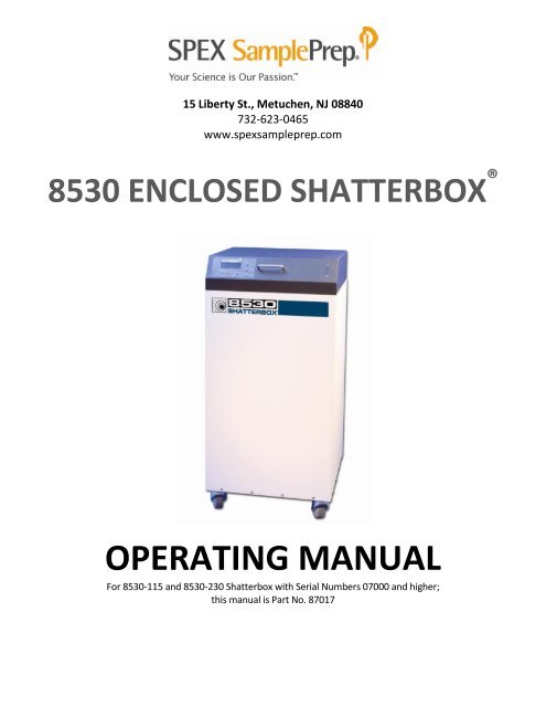
8530 Shatterbox Manual 100713 abridged - SPEX SamplePrep
8530 Shatterbox Manual 100713 abridged - SPEX SamplePrep
8530 Shatterbox Manual 100713 abridged - SPEX SamplePrep
Create successful ePaper yourself
Turn your PDF publications into a flip-book with our unique Google optimized e-Paper software.
2.0 SPECIFICATIONS<strong>8530</strong> <strong>Shatterbox</strong>Type of mill: grinding millGrinding mechanism: grinding containersWeight (without grinding container): 225 lbs. (102 Kg)Dimensions: 19 in (48 cm) x 19 in (48 cm) x 40 in. (102 cm)Grinding Vials Available (see page 20 for more information):8501 Hardened Steel Grinding Container8504 Tungsten Carbide Grinding Container8505 Alumina Ceramic Grinding Container8506 Zirconia Grinding Container8507 Small Hardened Steel Grinding Container8508 Small Tungsten Carbide Grinding Container8521 Large Hardened Steel Grinding ContainerNOTE: In practice, the sample capacity of any particular grinding container depends on theproperties of the sample, particle-size requirements, and other considerations.Electrical: available in 115 60Hz (10-amp fuse) or 230V 50Hz (5-amp fuse).Cord: 115V 60Hz version, 3-prong grounded cord supplied.230V 50Hz version, with European CEE 7/7 two-prong plug supplied.NOTE: Operator is responsible for supplying alternate line cord/plug if required.Fuses: 115V 60Hz version, 10-amp slow-blow fuse in inlet module,230V 50Hz version, 5-amp slow-blow fuse in inlet moduleImportant: these fuses are "slow-blow" fuses, meant to withstand a temporary voltagepeak in excess of the fuse's current rating. (Electric motors of the type used in the<strong>Shatterbox</strong> draw more amperage than normal while getting up to speed.) Whenreplacing a fuse, remember to unplug the <strong>Shatterbox</strong> first, and always use a "slow-blow"type fuse.Motor: a 1/3 horsepower dual-winding 825-RPM motor powers the <strong>8530</strong> <strong>Shatterbox</strong>.The low horsepower rating of the motor is based on its low fixed speed, but the motorhas high torque (especially when starting up) and is more powerful than its HP powerrating implies.Safety Features: Lid Interlock prevents mill from running if lid is not closed and keeps lid lockeddown for 5 seconds after motor shuts off to allow mechanism to come to a stop.Recommended operating conditions: indoors, in ambient air, temperature between 40 o and90 o F. (4 o – 35 o C), humidity between 0% and 95%.Page 4 of 28 <strong>SPEX</strong> <strong>SamplePrep</strong> LLC January 2010
<strong>8530</strong> <strong>Shatterbox</strong>3.0 UNPACKINGThe <strong>8530</strong> <strong>Shatterbox</strong> mechanism and its cabinet are shipped assembled, and carefully packedto avoid damage during shipping. Any visible damage to the shipping container shouldimmediately be reported to the carrier. If there is no visible damage, remove all packingdocuments from the exterior of the box, and after completion of your inspection, file in yourrecords.Before unpacking the <strong>8530</strong> <strong>Shatterbox</strong>, place the shipping carton upright and as close aspossible to the mills intended location. Open the top of the shipping box. Remove the top andbody of the carton. Note that if the tape holding the carton’s bottom piece together is slit onone side, that flap can be folded down and the <strong>Shatterbox</strong> rolled off after unlocking the casters.A plug-in line cord, an extra set of 51793 drive belts, an extra set of fuses, and a 31688 FrictionDisc are included with your new <strong>Shatterbox</strong>. One Friction Disc (a circle of thin rubber matting)should always be kept in the recess off the capsule container, to cushion the grinding container,reduce the noise of the grinding, and prevent unnecessary and rapid wear of the clamp andcapsule retainer.Move the mill to the location where it is likely to stay, lock the casters, and open the lid. Pleasenote that the <strong>Shatterbox</strong> should always be installed and operated on a level surface. Check thepower switch, which is on the back of the cabinet, next to the electrical inlet (Diagram C, Item48); this switch should be in the off position (the 0 should be pushed in) when the power cord isfirst attached. Look for any hidden damage that may have occurred during shipping.The <strong>8530</strong> <strong>Shatterbox</strong> comes fully assembled. However, before plugging the <strong>Shatterbox</strong> in andusing the controls for the very first time, first inspect the drive mechanism to make sure it isproperly linked and aligned. The <strong>Shatterbox</strong> was tested before shipment, but there are fourflexible belts connecting two drive arms, one on the motor and one on the capsule retainer.The belts can become dislodged during shipping. If the <strong>Shatterbox</strong> is run with the drivemechanism uncoupled or misaligned, damage can result.To inspect the drive mechanism, remove the access panel on the back of the case. (Note that ingeneral this panel should not be removed without unplugging the power cord.) Check the beltlinkage between the arm on the motor and the arm on the rotating funnel on the bottom of thecapsule assembly. The two arms should be parallel and unbent, connected by four belts (Orings)in a diamond pattern that overlaps at the corners (Diagram B, item 34). (The coupling armis attached to the top of the motor shaft. The eccentric arm is attached to the bottom of therotating funnel.) Spin the arms by hand; the motor arm and the funnel arm should rotatetogether smoothly.If the drive belts have come off, replace them as pictured in Diagram B: in a diamond pattern,two belts up and two belts down. Spin the arms by hand.Page 5 of 28 <strong>SPEX</strong> <strong>SamplePrep</strong> LLC January 2010
<strong>8530</strong> <strong>Shatterbox</strong>3.0 UNPACKING (Cont’d)If either arm has become bent, straighten it; the arms are made of a soft alloy which can bebent without harming it. Spin the coupling arm by hand; the eccentric arm and the funnelshould rotate together freely. The hubs of the coupling arm and the eccentric arm should bebetween 1/16” and 1/8” apart; if they are not, the coupling arm may have ridden up or downthe motor shaft. Correct this by loosening the setscrews holding the coupling arm, andadjusting its position on the motor shaft. When the drive belts are aligned and the hubs of thetwo arms properly separated, tighten the setscrews (use a 1/8” Allen wrench).As re-installing the access panel, note the electrical inlet, on/off switch, and the fuse holder onthe left side of the access panel opening. The 115V 60Hz <strong>Shatterbox</strong> takes two 10-amp “slowblow” fuses; the 230V 50Hz unit takes two 5-amp “Slow Blow” fuses.Plug the cabinet power cord into an approved electrical outlet: in North America, a 3 pronggrounded 115V outlet on a circuit fused at 20 amps. The 230V/50Hz <strong>Shatterbox</strong> is equippedwith a standard European 2 prong plug that in some countries may have to be replaced to suitlocal electrical codes. The 230V power cord conforms to European wiring color codes.If everything seems to be okay, proceed to the next section “SETTING UP.”Control PanelElectrical InletModule at RearLid AssemblyCasters<strong>8530</strong> <strong>Shatterbox</strong>Page 6 of 28 <strong>SPEX</strong> <strong>SamplePrep</strong> LLC January 2010
4.0 SETTING UP<strong>8530</strong> <strong>Shatterbox</strong>After the initial unpacking and setup of the <strong>Shatterbox</strong>, you are ready to prepare the unit foractual use.As you make the <strong>Shatterbox</strong> ready to grind samples, become familiar with the grindingContainer you will use. The sample is placed in a container with a puck (and sometimes a ring);then the container is swung in a tight circle while the puck (and ring) crush the sample againstthe bottom and wall of the container. Most of the <strong>Shatterbox</strong> containers have an O-ring orgasket that prevents leakage during grinding. Grinding containers are available in several sizesand in a range of materials to minimize objectionable contamination: hardened steel (Cat. Nos.8501, 8507, and 8521), tungsten carbide (Cat. Nos. 8504, 8508), alumina ceramic (Cat. No.8505), and zirconia ceramic (Cat. No. 8506). See page 18 for more informationBefore actually operating your new <strong>8530</strong> <strong>Shatterbox</strong>, it is important that you become familiarwith its special features. This section explains in detail how each part of the <strong>Shatterbox</strong> works.Directions for operation (minus these detailed descriptions) are given in “Operations.” Thereare four important conditions of operation, which bear repeating:1. ALWAYS CLAMP A CONTAINER IN PLACE WHEN RUNNING THE SHATTERBOX.2. DO NOT OVERTIGHTEN THE CLAMP.3. DO NOT OPEN THE LID UNTIL THE LID LATCH IS DISENGAGED.4. ALWAYS UNPLUG THE MILL BEFORE OPENING THE CABINET ACCESS PANEL.While familiarizing yourself with the operation of the <strong>Shatterbox</strong> you may wish to clamp inplace a grinding container without its puck/ring. Read the clamp instructions first.4.1 Locking CastersAll four casters swivel, and can be locked and unlocked with the foot. Each caster has adownward sloping pedal with a small tab projecting up. To lock the casters, press the pedaldown. To unlock the casters, push the tab back. To move the <strong>8530</strong> <strong>Shatterbox</strong> easily, unlock thecasters; to keep it in place, lock them. Always lock the casters before operating the <strong>Shatterbox</strong>.4.2 Pneumatic CylindersThere is one on either side of the lid, to hold it firmly in the open or closed positions. Open andclose the lid several times to get the “feel” of lowering the lid gently. Keep fingers and objectsoff the rim of the <strong>Shatterbox</strong> cabinet when lowering the lid, as the pneumatic cylinders will notslow its descent during the last few inches.4.3 Safety InterlockThe <strong>8530</strong> <strong>Shatterbox</strong> is designed so the lid cannot be lifted while the capsule retainer is moving.When the start button is pushed, it activates a solenoid that locks down the lid. Not until thelid locks down will the <strong>Shatterbox</strong> motor start. At the end of a run when the timer reachesPage 7 of 28 <strong>SPEX</strong> <strong>SamplePrep</strong> LLC January 2010
4.3 Safety Interlock (Cont’d)<strong>8530</strong> <strong>Shatterbox</strong>zero, the motor shuts off, the timer displays RUN COMPLETE, and the lid stays latched for 5seconds to allow the grinding mechanism to slow down. After 5 seconds the lid unlatches withan audible click, and the timer re-sets. Always wait until the lid is unlatched before opening it.If the safety interlock cannot engage, the mill will not start, and ERROR: LATCH FAILUREappears in the timer display. When the problem has been corrected and the Interlock canengage, the ERROR display will continue until the stop button is pushed. Only when the timesetting (example: 3:00 REMAINING) reappears in the display can the <strong>Shatterbox</strong> be started.The only exposed part of the Safety Interlock is a U-shaped metal latch which protrudes fromthe inside lip of the lid and can be seen when the lid is lifted. Please do not damage this latch bytrying to open the lid before the latch disengages. If this part of the interlock is damaged andcannot latch properly, the <strong>Shatterbox</strong> will not start.4.4 Cam-Action ClampThe cam-action of the clamp makes it possible to hold any <strong>SPEX</strong> <strong>Shatterbox</strong> grinding containerfirmly in place without applying excessive pressure to the lever. The clamp can also be adjustedeasily for containers of different heights, or to compensate for wear. It is absolutely necessaryto adjust the clamp properly before using it, as overtightening the clamp can damage it. Suchdamage is not covered by the warranty. The different parts of the clamp are illustrated inDiagram A.To use the clamp, first swing the clamp arm to the left side of the cabinet and the clamp leverto the right. Then place a grinding container squarely in the recess of the capsule retainer. (Ifthe container is not firmly seated, it can work itself loose during grinding.) The use of a 31688Friction Disc in the capsule retainer recess, under the grinding container, is recommended at alltimes; it lessens noise, aids the gripping action of the clamp, and prevents rapid wear of thecapsule retainer.When the grinding container is in place, swing the clamp arm to the right, so the guide fits overthe boss (raised protuberance) in the center of the container lid. Then bring up the clamp leverso that the open gate at its base fits over the end clamp arm; the roller in the clamp leverassembly should rest in the curved recess of the clamp arm. Swing the clamp lever over to theleft. If the lever meets strong resistance, STOP! The clamp is not properly adjusted and mustbe loosened. Overtightening the clamp can break the cam mechanism.The best way to adjust the clamp is to screw the guide back into the clamp bar until contactwith the grinding container is loose. Then extend (unscrew) the guide until the clamp becomessnug. Ideal tightness for the clamp is just past the point where the grinding container can berotated with the clamp lever down. When the clamp is perfectly adjusted, the lever will meetmoderate resistance as it is pushed through the top of its arc, then close easily.Page 8 of 28 <strong>SPEX</strong> <strong>SamplePrep</strong> LLC January 2010
4.4 Cam-Action Clamp (Cont’d)<strong>8530</strong> <strong>Shatterbox</strong>If the guide is set too loose, the lever will meet little or no resistance, and the grindingcontainer can be rotated in place; disengage the lever and tighten the guide. If the guide is settoo tight, the lever will meet strong resistance as it approaches the vertical. We repeat, neverforce the lever, but disengage it and loosen the guide.The guide may be tightened or loosened by screwing it away from, or toward the clamp arm.First disengage the locking pin by pushing its flange toward the spring. Then screw the guideaway from the clamp arm to tighten it, or toward the clamp to loosen it. Test the fit by closingthe clamp. When the clamp is adjusted, make sure the locking pin is engaged.4.5 Controls4.5.1 Main Power Switch (Diagram C, Item 48)This is the rocker switch on the back of the cabinet, next to the electrical inlet. It controls theflow of current to the controls and motor. When you press this switch to the on position (I) thetimer display will light up. The timer can now be programmed. Pressing this switch to the offposition (0) will switch off power to the mill.4.5.2 Digital TimerThe timer includes a minutes:seconds numerical display, push-buttons for the start, stop andpause functions, and buttons to change the timer setting. The display indicates theprogrammed grinding time when the mill is not running: 3:00 REMAINING means the<strong>Shatterbox</strong> is programmed for a 3-minute run. During a run the timer counts down the timeremaining in 5-second increments: 2:05, 2:00, 1:55, etc. The time is displayed in minutes andseconds; for example, 1:30 equals one minute and thirty seconds.Time is programmed up or down, in 5-second increments, by pressing the up/down buttonsbelow the timer display.The timer display also includes three status screens:PAUSED is displayed when the pause button has been pressed;RUN COMPLETE is displayed for 5 seconds after the run is over;, andERROR: LATCH FAILURE is displayed when the lid interlock cannot engage.NOTE: Before setting the timer and operating the <strong>8530</strong> <strong>Shatterbox</strong>, clamp a grindingcontainer firmly in place. Also, while learning how to operate the <strong>Shatterbox</strong> you maywant to use a grinding container with its puck/ring grinding elements removed.Page 9 of 28 <strong>SPEX</strong> <strong>SamplePrep</strong> LLC January 2010
4.5 Controls (Cont’d)<strong>8530</strong> <strong>Shatterbox</strong><strong>8530</strong> <strong>Shatterbox</strong> Digital Timer Screen and Controls4.5.3 Setting the TimerWhen power is switched on, the timer will first display the <strong>SPEX</strong> logo, followed quickly by:<strong>SPEX</strong> SAMPLEPREP<strong>8530</strong> SHATTERBOXThe timer will then display the default timer setting of three minutes (3:00). Assuming agrinding container is clamped into the capsule retainer and the lid is down, pressing START willinitiate a run of 3 minutes. First there will be a delay of several seconds for the lid latch toengage, then the timer will start counting down in 5-second increments: 2:55, 2:50, 2:45, etc.Every time power is turned off and back on, the timer will revert to the 3:00 default setting. Tokeep another timer setting, leave the power on. If power is not interrupted, the timer willdisplay the most recently programmed setting.Set the grinding time with the four buttons below the timer display. There are up and downbuttons for minutes, and up and down buttons for seconds. The MIN buttons will change theminute setting 1 minute at a time, and the SEC buttons will change the seconds setting 10seconds at a time. 10:00 is the maximum running time; increasing the minutes setting past 10will take the setting to zero. 50 is the maximum setting for seconds; increasing the secondspast 50 will take the setting to zero. If a button is pushed and immediately released, it willchange its setting by one unit.Page 10 of 28 <strong>SPEX</strong> <strong>SamplePrep</strong> LLC January 2010
<strong>8530</strong> <strong>Shatterbox</strong>4.5.4 Starting and Running the <strong>Shatterbox</strong>Push the start button to begin a grinding cycle. There will be a short pause while the lidinterlock engages, and then the <strong>Shatterbox</strong> motor will start. The timer counts down 5 secondsat a time, showing the time left in the run. When the timer reaches zero and the motor shutsoff, the timer will display RUN COMPLETE for 5 seconds while the lid latch stays locked. Thisallows the capsule retainer mechanism to slow down. When the interlock releases the lid (withan audible click), the timer display will return to its prior setting. Never try to open the lidbefore the interlock releases; this can damage the lid latch.4.5.5 Using the Stop and Pause ButtonsTo stop the mill during a run, push the stop button. This will shut off the motor and re-set thetimer. RUN COMPLETE will be displayed for 5 seconds and the lid will stay latched. After 5seconds the original timer setting will re-appear and the lid latch will release.To have the mill pause during a run and retain the timer setting, push the pause button. Themotor will shut off and PAUSED will appear in the display. The lid latch will not release. Toresume the run, push START; the timer will briefly display the exact number of seconds left inthe run and then count down in 5-second increments. To abort the run, push STOP; RUNCOMPLETE will be displayed for five seconds and the lid latch will release.4.5.6 Timer/Lid Latch InterlockThe timer is connected to the safety interlock, a latch in the lid that hooks under the front edgeof the cabinet when the START button is pressed, and locks the lid down. If the <strong>Shatterbox</strong> lidcannot be locked down when START is pressed, the motor will not start and ERROR: LATCHFAILURE will appear in the timer display. When this happens, correct any problems with theinterlock latch, then press STOP to clear ERROR: LATCH FAILURE from the display, and restorethe timer setting. Only when the timer setting is restored can the <strong>Shatterbox</strong> be started again.Page 11 of 28 <strong>SPEX</strong> <strong>SamplePrep</strong> LLC January 2010
5.0 OPERATION<strong>8530</strong> <strong>Shatterbox</strong>The following sequence is typical. It supposes familiarity with the chief features of the<strong>Shatterbox</strong>, as described in “SETTING UP.” First, these cautions:Never operate the <strong>Shatterbox</strong> without a grinding container and friction disc clamped firmly inplace. (If it is necessary to run the <strong>Shatterbox</strong> without grinding a sample, remove the grindingelement(s) from the container.) Never remove the access panel in the back of the cabinetunless the mill is first unplugged.1. Switch the power on. The timer display will light up. Initially it will flash the <strong>SPEX</strong><strong>SamplePrep</strong> logo and then display <strong>SPEX</strong> SAMPLEPREP/<strong>8530</strong> SHATTERBOX, but this willshortly change to the default timer setting of 3:00.2. Program the timer, using the buttons immediately below the numerical display. The lefthandpair of buttons controls the minutes, and the right-hand pair of buttons controls theseconds.3. Load the grinding container with sample. If running the <strong>Shatterbox</strong> without grindinganything, remove the grinding element(s) from the container. Clamp the container into thecapsule retainer. Make sure that the friction disc is properly placed and the grindingcontainer is firmly seated. If the clamp is properly adjusted, the clamp lever should worksmoothly with some resistance at the top of its arc, but you should not be able to rotate thecontainer in place once the clamp lever is down. If the clamp is too tight or too loose,adjust it.4. Shut the lid, and press the start button. There will be a brief pause while the lid locks down,and then the <strong>Shatterbox</strong> motor will start. As it runs, the timer display will count down theminutes and seconds remaining, in 5-second increments. When the timer reaches zero,RUN COMPLETE will appear in the timer display for five seconds while the lid remainslatched; this gives the grinding mechanism time to slow down. Then the timer setting willre-appear and the lid will unlatch, with an audible click. Always wait for the lid to unlatchbefore opening it.Open the lid, unclamp the grinding container, and remove it for emptying and cleaning.If ERROR: LATCH FAILURE is displayed instead of numerals when the start button is pressed, theinterlock has not properly engaged. Clear the timer by pressing the stop button, and correctthe problem.Page 12 of 28 <strong>SPEX</strong> <strong>SamplePrep</strong> LLC January 2010
5.1.2 Choice of Grinding-Container Size<strong>8530</strong> <strong>Shatterbox</strong>There are four sizes of <strong>Shatterbox</strong> grinding container: small, medium, large, and extra large. Topick the correct size it is necessary to know the minimum amount of sample you have to grind,its approximate density, and the fineness of grind desired, as each may affect your final choice.The typical sample capacities of each container type are given below in grams, assuming asample of the density of quartz sand, rock, etc. (approx. 2 to 3-1/2) and the requirement topulverize the sample to around 325 mesh (44 microns). The sample capacity volume RANGE,which is much broader, is given in ml. If you are unsure which <strong>Shatterbox</strong> grinding container toselect, consult our product specialists. You can also send your samples in for evaluation andtest grinding.Small:Medium:Large:8507 Small Hardened Steel and 8508 Small Tungsten Carbide grindingcontainers. Each has a puck-shaped grinding element. Typical sample capacity8-12 grams, sample volume range 5 - 15 ml. Requires 8507R Rack to operate one8507/8508 or three simultaneously.8505 Alumina Ceramic and 8506 Zirconia Ceramic grinding containers. Each hasa puck-shaped grinding element. Typical sample capacity 20-30 grams, samplevolume range 15 - 40 ml.8501Hardened Steel and 8504 Tungsten Carbide grinding containers. Each has apuck and ring. Typical sample capacity 40-60 grams, sample volume range 20 -70 ml.Extra Large: 8521 Large Hardened Steel grinding container, with puck and ring. Typicalsample capacity 60-100 grams, sample volume range 30 - 120 ml.The sample volume ranges given above are estimates, not absolute limits. The upward limit onthe weight/volume of a given sample for a given grinding container is really determined by thepoint where the mill stops grinding the sample satisfactorily. This limit can vary with the typeof the sample and its particle size. The lower limit on the size of the sample is usually reachedwhen the sample becomes highly contaminated and is hard to recover. (If very little sample isground there is a lot of direct contact between the grinding element or elements and thecontainer, and under these conditions the tungsten carbide and ceramic grinding containers aremore likely to become chipped.) Avoid grinding large chunks of sample, as these can either jamthe grinding container or damage it; even if they grind satisfactorily they will probably not grindconsistently. We recommend reducing the feed size to at least 1/4" for the tungsten carbideand steel grinding containers, and to 1/8" for the alumina and zirconia ceramic grindingcontainers.When developing a procedure for your combination of <strong>Shatterbox</strong> and grinding container, try asample size near the middle of the given range(s). Grind for two minutes in steel or tungstencarbide, or four minutes in alumina or zirconia. If grinding is not satisfactory but the sample isnot caking, try increasing the grinding time or decreasing the sample size, or both. If cakingoccurs, consult the Handbook of Sample Preparation and Handling for information aboutgrinding aids.Page 14 of 28 <strong>SPEX</strong> <strong>SamplePrep</strong> LLC January 2010
<strong>8530</strong> <strong>Shatterbox</strong>5.1.4 Emptying and Cleaning the Grinding Container (Cont’d)A cleaned grinding container, which will not be used for some time, should be stored in a plasticbag. Hardened steel grinding containers should always be dried and stored carefully, as theyare prone to surface rusting.5.1.5 Grinding HintsIt is risky to give exact formulas for sample grinding because there are so many variables. Fewtypes of sample have the same grinding characteristics. Grinding containers are made ofdifferent materials, all of which grind differently; furthermore, a worn grinding container will beless efficient than a new one. While there are many analytical techniques that require finelyground samples, the necessary particle size for proper analytical results may vary frominstrument to instrument and from sample to sample. Consequently these guidelines aregeneral.For any grinding container, the smaller the overall sample size, the finer it can be ground in agiven time. Unless a sample cakes during grinding, the longer it is ground, the finer it will get.Particle size can almost always be lowered further by reducing the sample size or lengtheningthe grinding time, or both.Dry grinding is relatively efficient for most brittle materials, but at small particle sizes (below 50microns) there is a tendency for particles to stick back together, or "cake." There are manygrinding aids to prevent caking. Water, alcohol, solvents, and other liquids can be added tocreate slurries whose mean particle size after grinding can be well below 10 microns, but formost analytical techniques the liquid must be removed before analysis. Dry grinding aidsinclude soap powders, detergents, stearates, and aspirin, all added to comprise 1% to 10% ofthe total sample weight. <strong>SPEX</strong> recommends a technique pioneered by Howard Kanare ofConstruction Technology Laboratory: ethylene glycol or propylene glycol is added to thesample in the amount of one drop for every five to ten grams of sample.In most analytical work it is important to reproduce particle size from sample to sample. Likeother laboratory mills, the <strong>Shatterbox</strong> requires a fixed routine to accomplish this: a uniformsample weight, grinding aid, grinding time, container, etc. You are welcome to telephone <strong>SPEX</strong><strong>SamplePrep</strong> LLC at 1-800 522-7739 or 732-549-7144 to discuss your particular application..Page 16 of 28 <strong>SPEX</strong> <strong>SamplePrep</strong> LLC January 2010
6.0 MAINTENANCE<strong>8530</strong> <strong>Shatterbox</strong>6.1 <strong>Shatterbox</strong> Part NumbersFollowing these written instructions are a parts list and diagrams (pages 22-24) of the<strong>Shatterbox</strong> mechanism and cabinet. Note that all <strong>SPEX</strong> parts have 5-digit inventory numbersthat must be used to order them. However, most of these parts also have 1-digit or 2-digitnumbers that correspond to the part's position in an engineering drawing. Example: thescrews, which hold the columns in place, are part no. 26 in Diagram A, but must be ordered as<strong>SPEX</strong> Part No. 50619.6.2 Cleaning the <strong>Shatterbox</strong>Depending on how dusty the working environment is it may be necessary to clean the<strong>Shatterbox</strong> regularly. The clamp and capsule retainer should be vacuumed or wiped off. Anyspilled powders or liquids should be wiped up immediately with a slightly damp cotton cloth afterevery use. This should minimize the buildup of any powders, mold/mildew, or unsightly gunk overthe life of the unit. To clean the <strong>Shatterbox</strong> mechanism, remove the access panel on the back ofthe cabinet (after unplugging the mill) and vacuum the exposed surfaces.For a properly functioning Cam-Action Clamp, it is absolutely necessary that the lever assemblyroller rotates smoothly (Diagram A, Item 13). Clean off any excess dust or dirt from the outersegments of the clamp, with special attention being placed on the hinge sections and on the roller.It may be necessary to oil the hinge and the roller from time to time. If the roller locks up, theclamp can be easily damaged.NOTE: It is important to unplug the unit from its power source before beginning any cleanupor maintenance work that is to be performed on the mill.6.3 Replacing Drive BeltsSpecial compound O-rings are used as drive belts (Diagram B, Item 34). When a drive belt fails,all four drive belts should be replaced by <strong>SPEX</strong> part no. 51793. (Neoprene O-rings will notwork.) Before installing new drive belts, check the clearance between the hubs of the couplingarm and eccentric arm (Diagram B, Items 28 and 35, respectively); the gap should be between1/16 inch and 1/8 inch (1.5 mm to 3 mm). If it is more or less than that, loosen the lock screwson the collar of the coupling arm with a 1/8-inch Allen wrench, adjust the clearance by movingthe coupling arm up or down on the motor shaft, then tighten the lock screws.Visually inspect the coupling arm and eccentric arm to make sure they are parallel, and notbent; if they are damaged, they should be replaced.Install the new drive belts in a diamond pattern, two up and two down as in Diagram B. Spinthe funnel (Diagram A, item 23) by hand to make sure the two arms spin together freely, andthe drive belts are parallel.Page 17 of 28 <strong>SPEX</strong> <strong>SamplePrep</strong> LLC January 2010
6.4 Clamp Mechanism Maintenance and Replacement<strong>8530</strong> <strong>Shatterbox</strong>All <strong>Shatterbox</strong>es have clamp levers that are anchored to the capsule retainer by yokes. Incurrent <strong>Shatterbox</strong> models (8500, 8515, <strong>8530</strong>), the yokes are attached with Allen bolts insertedfrom the top, so they can be tightened easily if the yokes become loose. Instructions are givenhere for tightening and replacing yoke bolts, and for replacing clamp arms and levers.If one of these bolts breaks and cannot be removed from the capsule retainer, or you arerepairing an earlier model <strong>Shatterbox</strong> with the yoke bolts inserted from beneath, call ourService Department for advice and parts availability. Contact information is in Section 12.0.The <strong>Shatterbox</strong> clamp mechanism is anchored to the capsule retainer by yokes: the long yoke(Diagram A, Item 19) holds the clamp arm (Diagram A, Item 14), and the short yoke (Diagram A,Item 12) holds the clamp lever assembly (Diagram A, Item 13). Each yoke is attached to thecapsule retainer by two Allen bolts (Diagram A, Item 10). If a yoke loosens, the bolts must betightened. To do this, remove the C-clip (Diagram A, Item 18) from one end of the pin (DiagramA, Item 17) that holds the clamp arm or lever, and push the pin out from that end. Use a 5/32-inch Allen wrench to tighten the loose bolts; you may wish to remove the bolts, clean them,and apply a locking agent before tightening them.Clamp arms and clamp levers are replaced in a similar way, by pushing the pin out of the yoke,removing the old arm or lever, replacing it, re-inserting the pin, and holding the pin in placewith a C-clip.6.5 Tightening or Replacing the YokesAll but a few of the early <strong>Shatterbox</strong>es have a long yoke (Diagram A, item 19) and swing shortyoke (Diagram A, item 12) that are fastened to the capsule retainers by Allen bolts insertedfrom above. If these bolts loosen, they can be tightened with an Allen wrench after removingthe pin holding the clamp arm or lever. To do this, remove one of the C-clips (Diagram A, item18) holding the pin (Diagram A, item 17) in place, and push the pin out from that end. In theunlikely event that the bolts shear and cannot be removed from above, or if you have one ofthose early <strong>Shatterbox</strong>es with the bolts inserted from below, it will be necessary to remove thefunnel to gain access to the underside of the capsule retainer. After detaching the uppersection of the mechanism (Diagram A, item 18 from item 22), invert it and remove the eccentricarm (Diagram B, item 35) by first taking out the small setscrew from the large slotted setscrew(Diagram B, item 27) and removing it. Then pull the funnel straight off the shaft. Wheninstalling either yoke, first clean the yoke and its mounting bolts to remove all traces of oil, andtreat each bolt with a locking agent to prevent loosening after assembly. When replacing thefunnel and eccentric arm make sure that the long side of the eccentric arm and the funnelcounterweight (Diagram A, item 9) are on the same side of the funnel, otherwise the gyratingmotion of the <strong>Shatterbox</strong> will be unbalanced.Page 18 of 28 <strong>SPEX</strong> <strong>SamplePrep</strong> LLC January 2010
6.6 Replacing the Rubber Columns<strong>8530</strong> <strong>Shatterbox</strong>To replace the rubber columns (Diagram A, item 7) first remove the older columns by removingthe retaining screws (Diagram A, item 26) that hold them, and pulling the old columns fromtheir sockets. Then place the new columns in those sockets and check and adjust the clearancebetween the eccentric and coupling arms as mentioned above. Once the correct clearance isestablished, drill holes through the new columns to allow insertion of the retaining pins.6.6 Changing the FusesIf the <strong>Shatterbox</strong> will not operate when the start button is pressed, it is possible that one orboth of the fuses may have blown. To access the fuses, first remove the power cord from theback of the <strong>Shatterbox</strong>. Then open the door on the fuse compartment by gently prying it openat the top and flipping it down. Use a small screwdriver to gently pry the red fuse holder out ofthe compartment, as shown in Figure 3. Remove the fuses and check them using a continuitytester. If either fuse is blown or defective, replace both with 3AG 10-amp, 230V slow-blowfuses for the 115V model, or 3AG 5-amp, 230V slow-blow fuses for the 230V model. Positionthe fuse holder such that the appropriate operating voltage appears on top. Return the fuseholder to the fuse compartment and close the access door. Check the window of the fusecompartment to make sure that it shows the appropriate voltage. If not, the fuse holder isupside down and must be turned around before attempting to operate the <strong>Shatterbox</strong>.PLEASE NOTE: If you have any questions about the operation and maintenance of your<strong>8530</strong> <strong>Shatterbox</strong>, please contact our specialists by phone at 1-800 LAB-<strong>SPEX</strong>(522-7739) or 732-549-7144, or by e-mail at sampleprep@spexcsp.com.Page 19 of 28 <strong>SPEX</strong> <strong>SamplePrep</strong> LLC January 2010
<strong>8530</strong> <strong>Shatterbox</strong>7.0 ACCESSORIES: GRINDING/MIXING VIALS(If not included in your Order, they are Available for Purchase at Additional Cost)8501 Hardened Steel Grinding ContainerOuter Dimensions (dia. x height): 17.5 x 7.5cm,Weight: 8kg Recommended Load: 20-50mlComplete with: Dish, Lid, Ring, Puck, & Gasket8504 Tungsten Carbide Grinding ContainerOuter Dimensions (dia. x height): 17.5 x 8cmWeight: 12.5kg Recommended Load: 20-60mlComplete with: Dish, Lid, Ring, Puck, & Gasket8505 Alumina Ceramic Grinding ContainerOuter Dimensions (dia. x height): 15.2 x 8cmWeight: 5kg Recommended Load: 15-40mlComplete with: Dish, Lid, Puck, & Gasket8506 Zirconia Grinding ContainerOuter Dimensions (dia. x height): 15.2 x 8cmWeight: 6kg Recommended Load: 15-40mlComplete with: Dish, Lid, Puck, & Gasket8521 Large Hardened Steel Grinding ContainerOuter Dimensions (dia. x height): 20.3 x 8.2cmWeight: 13kg Recommended Load: 30-100mlComplete with: Dish, Lid, Ring, Puck, & GasketPage 20 of 28 <strong>SPEX</strong> <strong>SamplePrep</strong> LLC January 2010
<strong>8530</strong> <strong>Shatterbox</strong>7.0 ACCESSORIES: GRINDING/MIXING VIALS (Cont’d)(If not included in your Order, they are Available for Purchase at Additional Cost)8507 Small Hardened Steel Grinding ContainerOuter Dimensions (dia. x height): 9 x 5.4cmWeight: 1.9kg Recommended Load: 5-20mlComplete with: Dish, Lid, Puck, & Gasket8508 Small Tungsten Carbide Grinding ContainerOuter Dimensions (dia. x height): 9.2 x 5.9cmWeight: 3.5kg Recommended Load: 5-20mlComplete with: Dish, Lid, Puck, & Gasket8507R RackHolds one or three 8507 or 8508 grinding containers.Rack base assembly and lid included; rack with threegrinding containers lifts easily in and out of<strong>Shatterbox</strong>. Please note that 8507 and 8508 containerscannot be mixed during the same run.31688 <strong>Shatterbox</strong> Friction DiscDurable rubber pad reduces operating noise andwear when placed under grinding container.51793 <strong>Shatterbox</strong> Drive BeltSpecial elastomer O-ring. Note: Drive belts shouldalways be replaced as a set to ensure properoperation, 4 required. For models 8500 and <strong>8530</strong>only.To Order any ofthese, or the aboveaccessories, callCustomer Service at800-522-7739 or 732-549-7144Page 21 of 28 <strong>SPEX</strong> <strong>SamplePrep</strong> LLC January 2010
<strong>8530</strong> <strong>Shatterbox</strong>This page contains restricted content. To download the full un<strong>abridged</strong> version of this manual,please visit our website at www.spexsampleprep.com or callCustomer Service at 732-623-0645.Page 22 of 28 <strong>SPEX</strong> <strong>SamplePrep</strong> LLC January 2010
<strong>8530</strong> <strong>Shatterbox</strong>This page contains restricted content. To download the full un<strong>abridged</strong> version of this manual,please visit our website at www.spexsampleprep.com or callCustomer Service at 732-623-0465.Page 23 of 28 <strong>SPEX</strong> <strong>SamplePrep</strong> LLC January 2010
<strong>8530</strong> <strong>Shatterbox</strong>This page contains restricted content. To download the full un<strong>abridged</strong> version of this manual,please visit our website at www.spexsampleprep.com or callCustomer Service at 732-623-0465Page 24 of 28 <strong>SPEX</strong> <strong>SamplePrep</strong> LLC January 2010
<strong>8530</strong> <strong>Shatterbox</strong>This page contains restricted content. To download the full un<strong>abridged</strong> version of this manual,please visit our website at www.spexsampleprep.com or callCustomer Service at 732-623-0465.Page 25 of 28 <strong>SPEX</strong> <strong>SamplePrep</strong> LLC January 2010
<strong>8530</strong> <strong>Shatterbox</strong>This page contains restricted content. To download the full un<strong>abridged</strong> version of this manual,please visit our website at www.spexsampleprep.com or callCustomer Service at 732-623-0465.Page 26 of 28 <strong>SPEX</strong> <strong>SamplePrep</strong> LLC January 2010
<strong>8530</strong> <strong>Shatterbox</strong>This page contains restricted content. To download the full un<strong>abridged</strong> version of this manual,please visit our website at www.spexsampleprep.com or callCustomer Service at 732-623-0465.Page 27 of 28 <strong>SPEX</strong> <strong>SamplePrep</strong> LLC January 2010
12.0 CONTACT US<strong>8530</strong> <strong>Shatterbox</strong>Within the United States, write, telephone, or e-mail us at:<strong>SPEX</strong> <strong>SamplePrep</strong> LLC15 Liberty St.Metuchen, New Jersey 08840Tel.: 732-623-0645Fax: 732-906-2492Website: www.spexsampleprep.comE-mail: sampleprep@spexcsp.comIn Europe, please contact our European Headquarters at:<strong>SPEX</strong> CertiPrep Ltd2 Dalston GardensStanmoreMiddlesex HA7 1BQUnited KingdomTel: +44 (0) 208 204 6656Fax: +44 (0) 208 204 6654Website: www.spexcertiprep.co.ukOutside the United States, contact the <strong>SPEX</strong> <strong>SamplePrep</strong> representative from whom you boughtyour equipment. A list of our current representatives is on our website, above.Page 28 of 28 <strong>SPEX</strong> <strong>SamplePrep</strong> LLC January 2010


