t230 grass trimmer t230x grass trimmer c230 ... - Shindaiwa USA
t230 grass trimmer t230x grass trimmer c230 ... - Shindaiwa USA
t230 grass trimmer t230x grass trimmer c230 ... - Shindaiwa USA

Create successful ePaper yourself
Turn your PDF publications into a flip-book with our unique Google optimized e-Paper software.
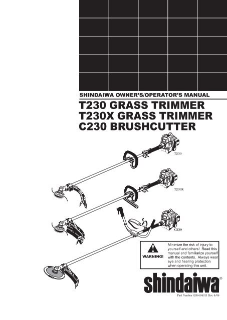
ENGLISHSHINDAIWA OWNER’S/OPERATOR’S MANUALT230 GRASS TRIMMERT230X GRASS TRIMMERC230 BRUSHCUTTERT230T230XC230WARNING!Minimize the risk of injury toyourself and others! Read thismanual and familiarize yourselfwith the contents. Always weareye and hearing protectionwhen operating this unit.®Part Number 62064-94013 Rev. 8/06
Introduction<strong>Shindaiwa</strong> 230-series hand held powerequipment has been designed and built todeliver superior performance and reliabilitywithout compromise to quality, comfort,safety or durability.<strong>Shindaiwa</strong>’s high-performance engines representthe leading edge of 2-cycle enginetechnology, delivering exceptionally highpower with remarkably low displacementand weight. As an owner/operator, you’llsoon discover for yourself why <strong>Shindaiwa</strong> issimply in a class by itself!IMPORTANT!The information contained in this owner's/operator's manual describes units availableat the time of publication.<strong>Shindaiwa</strong> Inc. reserves the right to makechanges to products without prior notice,and without obligation to make alterationsto units previously manufactured.ContentsPAGEAttention Statements....................................3Safety Information........................................4Safety Labels.................................................4Unit Description............................................5Specifications................................................5Assembly.......................................................6Mixing Fuel.................................................11Starting the Engine....................................12Stopping the Engine...................................12Adjusting Engine Idle.................................13Checking Unit Condition...........................13Shoulder Strap............................................13Using the Trimmer (T230) .......................14Using the Brushcutter (C230)..................15Maintenance................................................16Long Term Storage.....................................19Blade Sharpening.......................................19Troubleshooting Guide..............................20Emission System Warranty.......................22Attention StatementsThroughout this manual are special“Attention Statements.”WARNING!A statement preceded by the triangularattention symbol and the word“WARNING” contains information thatshould be acted upon to prevent seriousbodily injury.CAUTION!A statement preceded by the word“CAUTION” contains information thatshould be acted upon to prevent mechanicaldamage.IMPORTANT!A statement preceded by the word“IMPORTANT” is one that possessesspecial significance.NOTE:A statement preceded by the word “NOTE”contains information that is handy to knowand may make your job easier.Read and follow thisoperators manual.Failure to do so couldresult in serious injury.Wear eye and hearingprotection at all timesduring the operationof this unit.Keep bystandersat least 50 feet (15 m)away during operation.Beware of thrown orricocheted objects.Do not operate this unitwith a blade unless theunit is equipped with a<strong>Shindaiwa</strong>-approvedhandlebar or barrier.Always wear a harnesswhen operating this unitwith a blade. A harnessis also recommended whenusing <strong>trimmer</strong> line.If unit is used as abrushcutter, beware ofblade thrust. A jammedblade can cause the unitto jerk suddenly and maycause the operator tolose control of the unit.IMPORTANT!The operational procedures described inthis manual are intended to help you getthe most from unit as well as to protectyou and others from harm. These proceduresare guidelines for safe operation undermost conditions, and are not intendedto replace any safety rules and/or lawsthat may be in force in your area. If youhave questions regarding your <strong>Shindaiwa</strong>power tool, or if you do not understandsomething in this manual, your <strong>Shindaiwa</strong>dealer will be glad to assist you. You mayalso contact <strong>Shindaiwa</strong>, Inc. at the addressprinted on the back of this manual.General Safety InstructionsWork SafelyTrimmers and brushcutters operate at veryhigh speeds and can do serious damage orinjury if they are misused or abused. Neverallow a person without training or instructionto operate this unit!WARNING!Never make unauthorized attachmentinstallations.WARNING!Use Good JudgmentNEVER run the engine when transportingthe unit.NEVER run the engine indoors! Makesure there is always good ventilation.Fumes from engine exhaust can causeserious injury or death.ALWAYS use the proper cutting tool forthe job.ALWAYS stop the unit immediately ifit suddenly begins to vibrate or shake.Inspect for broken, missing or improperlyinstalled parts or attachments.NEVER extend trimming line beyondthe length specified for your unit.ALWAYS keep the unit as clean aspractical. Keep it free of loose vegetation,mud, etc.ALWAYS hold the unit firmly with bothhands when cutting or trimming, andmaintain control at all times.ALWAYS keep the handles clean.ALWAYS disconnect the spark plugwire before performing any maintenancework.ALWAYS, if a saw blade should bindfast in a cut, shut off the engine immediately.Push the branch or tree to easethe bind and free the blade.
General Safety InstructionsStay AlertYou must be physically and mentally fit tooperate this unit safely.WARNING!Never operate powerequipment of any kindif you are tired or if you are under theinfluence of alcohol, drugs, medicationor any other substance that could affectyour ability or judgement.WARNING!The Properly Equipped OperatorWear hearing protection devices and abroad-brimmed hat or helmet.Wear close-fittingclothing to protect legs andarms. Gloves offer addedprotection and are stronglyrecommended. Do notwear clothing or jewelrythat could get caught inmachinery orunderbrush. Securelong hair so thatit is above shoulderlevel. NEVERwear shorts!Always wear eyeprotection such as goggles orsafety glasses to shield againstthrown objects.Always wear aharness when operating aunit equipped with a blade.Always operate withboth hands firmly grippingthe unit.Minimize the Risk of Fire!NEVER smoke or light fires near theunit.ALWAYS stop the engine and allow itto cool before refueling. Avoid overfillingand wipe off any fuel that may havespilled.ALWAYS inspect the unit for fuel leaksbefore each use. During each refill,check that no fuel leaks from aroundthe fuel cap and/or fuel tank. If fuelleaks are evident, stop using the unitimmediately. Fuel leaks must be repairedbefore using the unit.ALWAYS move the unit to a place wellaway from a fuel storage area or otherreadily flammable materials beforestarting the engine.NEVER place flammable material closeto the engine muffler.NEVER run the engine without thespark arrester screen in place.Keep a proper footingand do not overreach.Maintain your balanceat all times duringoperation.Wear appropriate footwear (non-skidboots or shoes): do not wear open-toedshoes or sandals. Never work barefooted!When operating with a blade, makesure the handle is positioned toprovide you with maximumprotection from contactingthe blade.Keep away from the rotating<strong>trimmer</strong> line or blade at all times,and never lift a movingattachment above waist-high.Always make sure the appropriatecutting attachment shield is correctlyinstalled and in good condition.Figure 1
Safety LabelsREAD THEOPERATOR’S MANUALWEAR HEARING AND ANSI Z87.1APPROVED EYE PROTECTION50 FEET(15m)KEEP BYSTANDERS AWAYAT LEAST 50 FEET (15m)T230IMPORTANT!Safety and Operation Information Labels:Make sure all information labels areundamaged and readable. Immediatelyreplace damaged or missing informationlabels. New labels are available from yourlocal authorized <strong>Shindaiwa</strong> dealer.BEWARE OF THROWN ORRICOCHETED OBJECTSDO NOT OPERATE THISMACHINE WITH A BLADE<strong>Shindaiwa</strong> Inc.19422-00028This label indicates the minimumdistance between front handle andrear grip per ANSI B175.3.T230XC230Figure 2Be Aware of the Working Environment (all units)Be extremelycareful ofslippery terrain,especially duringrainy weather.Avoid long-term operationin very hot or very coldweather.50FEETMake sure bystanders or observersoutside the 50-foot “danger zone”wear eye protection.Reduce the risk ofbystanders being struckby flying debris. Makesure no one is within 50feet (15 meters)—that’sabout 16 paces—of anoperating attachment.Figure 3If contact is made witha hard object, stop theengine and inspect thecutting attachment fordamage.Be constantly alert for objectsand debris that could be throwneither from the rotating cuttingattachment or bounced from ahard surface.26105Always make surethe appropriate cuttingattachment shield iscorrectly installed.Beware of a coasting blade when brushcuttingor edging. A coasting blade can injure whileit continues to spin after the throttle trigger isreleased or after the engine is stopped.ALWAYS clear your work area of trash or hidden debris that could bethrown back at you or toward a bystander. When operating in rocky terrainor near electric wires or fences, use extreme caution to avoid contacting suchitems with the cutting attachment.
Unit DescriptionUsing the accompanying illustrations asa guide, familiarize yourself with this unitand its various components. Understandingthe product helps ensure top performance,long service life, and safer operation. SeeFigure 4.WARNING!Do not make unauthorized modificationsor alterations to any of these unitsor their components.GearcaseTrimmer HeadGearcaseOuter TubeCuttingAttachmentShieldOuter TubeIgnitionSwitchHandle(for <strong>trimmer</strong> use only)HandleBarrierGripThrottleTriggerGripIgnitionHanger SwitchThrottleTriggerTankProtector T230GRASS TRIMMERTankProtectorSparkPlugFuelTankSparkPlugFuelTankT230XGRASS TRIMMERTrimmer HeadCutting AttachmentShieldThrottleTriggerIgnitionSwitchShoulderStrapSparkPlugSpecificationsFigure 4BrushcutterBladeGearcaseT230 Dry Weight (less attachments).........................4.6 kg/10.2 lb.T230X Dry Weight (less attachments).......................4.7 kg/10.4 lb.C230 Dry Weight (less attachments).........................4.9 kg/10.8 lb.Engine Model............................................................. <strong>Shindaiwa</strong> S230Engine Type.............................. 2-cycle, vertical-cylinder, air-cooledBore x Stroke........................................... 32 x 28 mm/1.26 x 1.10 in.Displacement.......................................................... 22.5 cc/1.4 cu. in.Maximum Power Output...... 1.1 HP (0.8 kW) @ 7500 RPM (min -1 )Fuel/Oil Ratio..................................................... 50:1 with <strong>Shindaiwa</strong>Premium 2-cycle mixing oilOuter TubeCutting AttachmentShieldHandlebarFuelTank TankProtectorC230BRUSHCUTTERFuel Tank Capacity.....................................................554 ml/18.7 oz.Carburetor Type................................ Walbro WYL, diaphragm-typeIgnition........................... One-piece electronic, transistor-controlledSpark Plug.................................................................... Champion CJ8(for EMC compliance use NGK BMR6A)Air Cleaner Type................... Non-reversible flocked filter elementStarting Method..........................................................................RecoilStopping Method..............................................................Slide switchTransmission Type..............................Automatic, centrifugal clutchw/bevel gear*Specifications are subject to change without notice.Prior to AssemblyBefore assembling, make sure you have allthe components required for a completeunit: Engine assembly. Outer tube assembly. Cutting attachment shield. Cutting attachment (<strong>trimmer</strong> head,or brushcutter blade). Correct operators handle (see page 8). Kit containing cutting attachmentshield mounting bracket and hardware,operator’s handle mounting bracket andhardware, gearcase tool holder, thismanual and tool kit for routine maintenance.Tool kits vary by model and mayinclude a hex wrench, spanner and acombination spark plug wrench/screwdriver.Carefully inspect all componentsfor damage.IMPORTANT!The terms “left”, “left-hand”, and “LH”;“right”, “right-hand”, and “RH”; “front” and“rear” refer to directions as viewed by theoperator during normal operation.
AssemblyDriveshaft/Powerhead All ModelsConnect the Outer Tubeto the Powerhead.1. Place the powerhead on a clean, flat surface,spark plug facing up. See Figure 6.2. Use the4 mm hexwrench toloosen thetube clampscrew.HexWrench3. Add somemoly-typeFigure 5EP grease tothe splineson the end of the mainshaft.Tube Clamp4. Slide the outer tube into the tube clampuntil the tube bottoms. If installation isdifficult, rotate the outer tube or mainshaftslightly until you feel the mainshaftsplines engage with the powerhead.5. Position the outer tube so that the ignitionswitch is facing up and the throttletrigger is down.Clamp must fit next to lineon outer-tube decalDecalClampC230 BrushcutterFigure 6IgnitionSwitchFigure 6AT230 Slide the outer tube into thepowerhead until the throttle gripjust contacts the tube clamp.C230 Slide the outer tube into thepowerhead until the installationdecal aligns with the tube clamp.See Figure 6A.T230MainShaftClampScrewGripOuter TubeThrottleTriggerCAUTION!TubeClampSpark Plug6. Tighten the clamp screw firmly.Do not force the shaft tube into thepowerhead! Excessive force can damagethe shaft tube and mainshaft.AssemblyHandleT230 - Connect the Handle tothe Outer Tube.1. Position the handle on the outer tubeforward of Handle Positioning Label asshown in Figure 7.2. Install the mounting bracket with thesocket head cap screws. Tighten thescrews finger-tight ONLY at this time.3. Locate the handle in the best positionfor operator comfort (usually about 10inches ahead of the throttle housing).4. Secure the handle by alternately tighteningthe four socket-head screws in adiagonal or “crisscross” fashion.Figure 7Socket-headCaps ScrewsOuter TubeHandleMounting BracketThrottleAssemblyHandle Positioning LabelT230X - Connect the Handle tothe Outer Tube.1. Position the handle on the outer tubeforward of Handle Positioning Label asshown in Figure 8.2. Install the barrier bar with the sockethead cap screws and nuts. Tighten thescrews finger-tight only at this time.3. Locate the handle in the best positionfor operator comfort (usually about 10inches ahead of the throttle housing).4. Secure the handle by alternately tighteningthe four socket-head screws in adiagonal or “crisscross” fashion.Figure 8Socket-headCaps ScrewsOuter TubeBarrierHandleThrottleAssemblyHandle Positioning Label
AssemblyHandlebar C230Ignition SwitchShoulder StrapHandle Positioning LabelAssemble the Handlebar.1. Position the handle over the outer tube.See Figure 9. Make sure the throttle leveris on the right-hand side of the outertube.ThrottleTriggerHanger2. Attach the handle mounting bracketusing the two socket-head cap screws.Tighten the screws finger-tight ONLY atthis time.3. Locate the handle forward of the HandlePositioning Label at the best position foroperator comfort.4. Using the hex wrench, securely tightenthe two handlebar cap screws.ThrottleCableProtector SleeveHandlebar5. Route the ribbed throttle cable tubealong the handlebar and outer tube. SeeFigure 9. Install the protector sleeve onthe outer tube.Mounting BracketOuter TubeSocket-HeadCap ScrewFigure 9AssemblyThrottle Linkage and Ignition Leads All ModelsLoosen thecylinder coverknob anddisconnect thespark plug capInstall the black wirebetween the two cableadjuster nuts.IgnitionGroundLeadCable Adjuster NutRemove the Cylinder Cover.1. Remove the cap from the spark plug.2. Loosen the black cylinder cover knob(about a dozen full turns are required),and then lift off the cylinder cover.NOTE:If the cover binds on the muffler outlet tube,pull gently on the corner of the cover asshown (see inset).Connect the Throttle Cable.Figure 11230131. Route the ribbed cable over the tubeclamp to the top left side of the engine.Lift the corner ofthe coverConnect thethrottle cable2. Install the black wire between the twocable adjuster nuts as shown. SeeFigure 11.3. Connect the S-shaped end of the throttlecable to the throttle lever on top of thecarburetor. See Figure 12.23014Figure 10Figure 12
AssemblyThrottle Linkage and Ignition Leads All ModelsAssemble and Adjustthe Throttle Cable.1. Insert the throttle-cable housing into thenotch on the fan cover, and clamp theground wire terminal between the fancover and the outer cable adjuster nut.See Figure 13.2. Tighten the two throttle cable adjusternuts.IMPORTANT!Adjust and tighten the cable nuts to allowapproximately 1/4-inch free play at thethrottle trigger.Cable AdjusterNutsRed WireBlack IgnitionWire3. Using finger pressure only, connectthe black ignition wire from the cabletube to the red ignition wire on thepowerhead. Wire routing must be asshown in the illustration with the blackwire located away from the throttle cableand carburetor linkage.4. Reinstall the engine cover and tightenthe captive engine cover screw.5. Reinstall the spark plug boot.Figure 13GroundWireGround WireTerminalReinstall the SparkPlug CapCAUTION!Routing of wiring must not interfere withthrottle operation.
AssemblyCutting Attachment Shield All ModelsSocket-HeadCap ScrewT230BoltT230X/C230BracketOuterTubeCuttingAttachmentShieldUpper ClampClamp ScrewShimNutsShimLine CutterShimRetainingNutFigure 14CuttingAttachment ShieldMounting PlateShimFigure 14AHex26013ScrewsNutCutting Attachment ShieldInstall the Cutting AttachmentShield T230/T230X/C230.1. Insert the cutting attachment shieldbetween the outer tube and the cuttingattachment shield mounting plate.See Figure 14.NOTE:It may be necessary to loosen the retainingnut and clamp screw to adjust cutting attachmentshield mounting plate.2. Fit the two shims and the bracket overthe outer tube and loosely install thefour socket-head cap screws. SeeFigure 14.3. Tighten the four socket-head cap screwsto secure the cutting attachment shield.CAUTION!Make sure the clamp screw and retainingnut are securely tightened before tighteningthe four socket-head cap screws.WARNING!NEVER operate the unit without thecutting attachment shield installedand tightly secured!Sub-Shield T230X and C230.(when <strong>trimmer</strong> head is in use)1. Attach the shield extension to thecutting attachment shield.WARNING!NEVER use this machine without subshieldwhen using a <strong>trimmer</strong> head.Sub-shieldFigure 15CAUTION!Cutting Attachment ShieldHookReceiverMake sure the sub-guard iscompletely hooked at the hookreceiver.HookTo Change Position ofLine Cutter.The line cutter can be positioned in2 positions to obtain different line lengthfor cutting.1. Remove the 2 hex screws with a 4 mmhex wrench. See Figure 14A.2. Rotate line cutter. See Figure 14A.3. Reinstall the two hex screws and tightenthem securely.WARNING!The line cutter is very sharp. Weargloves to protect your hands whenhandling.NOTE:Be careful to not lose the 2 nuts in the cuttingattachment shield, they are not captured.
AssemblyTrimmer Head C230/T230/T230XHolder23019Install the<strong>trimmer</strong>headRemove theretainingplugInstall the Trimmer Head.OutputShaftModelT230Holder BHolder AThreadon the<strong>trimmer</strong>headFigure 16 Figure 171. Turn the unit over so that the gearcaseoutput shaft faces UP.2. (T230) Remove and discard the plasticretaining plug. See Figure 16.(T230X/C230) Remove the shaft boltand bolt guard using the combinationspark plug wrench/screwdriver. SeeFigure 17.Shaft BoltBolt GuardOutputShaftModelC230/T230XHolderBHolderA3. Rotate the holder until the hole in theholder aligns with the notch on thegearcase flange. Use the long end of thehex wrench to lock the output shaft inposition. See Figure 16 or 17.IMPORTANT!The <strong>trimmer</strong> head has a left-hand thread.Turn the <strong>trimmer</strong> head counter-clockwiseto install and clockwise to remove.4. While holding the hex wrench, threadthe <strong>trimmer</strong> head onto the output shaft,turning counter-clockwise.5. Using hand pressure only, tighten the<strong>trimmer</strong> head firmly on the gearshaft.6. Remove the hex wrench.7. Adjust the <strong>trimmer</strong> line length to reachno further than the line cutter on thecutting attachment shield. Trim to thecorrect length if necessary.WARNING!A standard <strong>grass</strong> <strong>trimmer</strong> unit with loophandle should NEVER be operated withblade-type attachments. For blade use,the <strong>trimmer</strong> must be fitted with a bicycletypehandlebar or barrier bar that is locatedin front of the operator to reduce therisk of the operator coming in contact withthe cutting attachment. (Per ANSI B175.3).When using a blade, the unit must beequipped with a harness or strap.The 230 unit should nowbe completely assembledand ready for use as a<strong>grass</strong> <strong>trimmer</strong>.AssemblyBlade C230/T230XShaft BoltBolt GuardHolder “B”Gear ShaftSafety ClipSafetyClipSlide the safety clip off-centerOutputShaftNOTE:When installing certain blades, it may be necessaryto temporarily remove the safety clip.CAUTION!Install the blade so its printed surfaceis visible to the operator when thebrushcutter is in the normal operatingposition.Holder “A”Hex WrenchFigure 19WARNING!The blade must fit flat against theholder flange. The blade mounting holemust be centered over the raised bosson blade holder A.Slide the saw bladein placeFigure 18 Figure 20Mount the Blade.Turn the brushcutter upside down so thegearcase output shaft is facing UP, and removethe shaft bolt, bolt guard and holderB from the gearcase shaft.1. Align the hole in blade holder “A” withthe matching hole in the gearcaseflange, and then temporarily lock theCenter the safetyclipoutput shaft by inserting a hex wrenchthrough both holes. See Figure 18.2. Slide the safety clip off-center.See Figure 18.3. Fit the blade over the safety clip andthen center it over the flange on holder“A”. See Figure 19.4. Lock the blade in place by centeringthe safety clip on the output shaft. SeeFigure 18.WARNING!Never operate the brushcutter withoutthe safety clip in place!10
AssemblyBlade C230/T230X (continued)Blade Holder BBladeHex Wrench(blade notshown forclarity)Output ShaftBolt Guard5. Install blade holder “B” on the outputshaft. See Figure 21. The recess in theholder must completely cover the safetyclip, and must fit tightly against theblade.6. Install the bolt guard and then the bladeretaining bolt. Using the combinationspark plug wrench/screwdriver, tightenthe bolt firmly in a counter-clockwisedirection.7. Remove the hex wrench.The C230 Brushcutter shouldnow be completely assembled.Figure 21Tighten the assembly(blade not shown for clarity)Mixing FuelCAUTION!n Some types of gasoline contain alcoholas an oxygenate. Oxygenatedgasoline may cause increased operatingtemperatures. Under certainconditions, alcohol-based gasolinemay also reduce the lubricatingqualities of some 2-cycle mixing oils.n Never use any type of gasolinecontaining more than 10% alcoholby volume! Generic oils and someoutboard oils may not be intendedfor use in high-performance 2-cycletype engines, and should never beused in your <strong>Shindaiwa</strong> engine.CAUTION!This engine is designed to operate ona 50:1 mixture consisting of unleadedgasoline and 2-cycle mixing oil only.Use of non-approved mixing oils canlead to excessive carbon deposits.n Use only fresh, clean unleaded gasolinewith a pump octane of 87 or higher.n Mix with 50:1 <strong>Shindaiwa</strong> Premium2-cycle mixing oil or with an equivalenthigh quality 2-cycle mixing oil.Examples of 50:1 mixing quantitiesn 1 gallon of gasoline to 2.6 oz. mixing oil.n 5 liters of gasoline to 100 ml. mixing oil.IMPORTANT!Mix only enough fuel for your immediateneeds! If fuel must be stored longer than30 days and oil with fuel stabilizeris not used, it should first be treated with afuel stabilizer such as STA-BIL.Filling the Fuel TankWARNING!Minimize the Risk of Fire!n STOP engine before refueling.n ALWAYS allow the engine to coolbefore refueling!n Wipe all spilled fuel and move theengine at least 10 feet (3 meters)from the fueling point and sourcebefore restarting!n NEVER start or operate thisunit if there is a fuel leak.n NEVER start or operate thisunit if the carburetor, fuel lines,fuel tank and/or fuel tank cap aredamaged.n NEVER smoke or light any fires nearthe engine or fuel source!n NEVER place any flammable materialnear the engine muffler!n NEVER operate the engine withoutthe muffler and spark arrester ingood working condition.1. Place the unit on a flat, level surface.2. Clear any dirt or other debris fromaround the fuel filler cap.3. Remove the fuel cap, and fill the tankwith clean, fresh fuel.4. Reinstall the fuel filler cap and tightenfirmly.11
Starting the EngineIMPORTANT!Engine ignition is controlled by a twoposition switch mounted on the throttlehousing labeled, “I” for ON or START and“O” for OFF or STOP.Make sure thecutting attachmentis clear ofobstructions!IMPORTANT!If the engine fails to start after several attemptswith the choke in the closed position,the engine may be flooded with fuel.If flooding is suspected, move the chokelever to the open position and repeatedlypull the recoil starter to remove excessfuel and start the engine. If the engine stillfails to start, refer to the troubleshootingsection of this manual.Figure 22230321. Slide the ignition switch to the “I” position(engine ON).ReturnTubeFigure 254. While holding the outer tube firmly withone hand, slowly pull the recoil starterhandle until resistance is felt, then pullquickly to start the engine.CAUTION!Do not pull the recoil starter to the endof the rope travel. Pulling the recoilstarter to the end of the rope travel candamage the starter.When the Engine Starts... After the engine starts, allow the engineto warm up at idle 2 or 3 minutes beforeoperating the unit. After the engine is warm, pickup the unit and clip on the harness if soequipped. See page 13. Advancing the throttle makes the cuttingattachment turn faster; releasingthe throttle permits the attachment tostop turning. If the cutting attachmentcontinues to rotate when the enginereturns to idle, carburetor idle speedshould be adjusted (page 13).Primer BulbFigure 232. Press the primer bulb until fuel can beseen flowing in the transparent returntube.IMPORTANT!The primer system only pushes fuelthrough the carburetor. Repeatedlypressing the primer bulb will not flood theengine with fuel.WARNING!The cutting attachment may rotatewhen the engine is started!5. When the engine starts, slowly move thechoke lever to the “OPEN” position. SeeFigure 26. (If the engine stops after theinitial start, close the choke and restart.)OpenStopping the EngineFigure 2723037Idle the engine briefly before stopping(about 2 minutes), then slide the ignitionswitch to the “O” (Engine OFF) position.ClosedFigure 2623036Figure 24230343. (Cold Engine Only) Set the chokelever to the CLOSED position.WARNING!Never start the engine from the operatingposition.12
Adjusting Engine IdleIdle AdjustingScrewFigure 28The engine must return to idle speedwhenever the throttle lever is released.Idle speed is adjustable, and must be setlow enough to permit the engine clutch todisengage the cutting attachment.Idle Speed AdjustmentWARNING!The cutting attachment must NEVERrotate at engine idle! If the idle speedcannot be adjusted by the proceduredescribed here, return the unit to your<strong>Shindaiwa</strong> dealer for inspection.1. Place the unit on the ground, then startthe engine, and then allow it to idle 2-3minutes until warm.2. If the attachment rotates when theengine is at idle, reduce the idle speedby turning the idle adjustment screwcounter-clockwise. See Figure 26.3. If a tachometer is available, the engine idlespeed should be final adjusted to 2,750(±250) RPM (min -1 ).4. Carburetor fuel mixture adjustments arepreset at factory on units with emissioncontrol systems and cannot be servicedin the field.Checking Unit ConditionNEVER operate the unit with the cuttingattachment shield or other protectivedevices (harness, ignition switch, bladeretention clip, etc.) removed!WARNING!A cutting attachment shield or otherprotective device is no guarantee ofprotection against ricochet. YOU MUSTALWAYS GUARD AGAINST FLYINGDEBRIS!Use only authorized <strong>Shindaiwa</strong> parts andaccessories with your <strong>Shindaiwa</strong> <strong>trimmer</strong>,brushcutter, or lawn edger. Do not makemodifications to this unit without the writtenapproval of <strong>Shindaiwa</strong>, Inc.ALWAYS make sure the cutting attachmentis properly installed and firmly tightenedbefore operation.NEVER use a cracked or warped cuttingattachment: If a properly installed attachmentvibrates, replace the attachment withnew one andre-check.ALWAYS stop the engine immediately andcheck for damage if you strike a foreignobject or if the unit becomes tangled. Donot operate with broken or damaged equipment.NEVER allow the engine to run at highRPM without a load. Doing so could damagethe engine.NEVER operate a unit with worn or damagedfasteners or attachment holders.NEVER cut with a dull blade. Doing so willincrease the risk of blade thrust and mayalso cause equipment damage.Shoulder StrapAdjust the shoulder strap so the shoulder padrests comfortably on the off-side shoulder andthe cutting path of the cutting attachmentis parallel to the ground. Make sure allhooks and adjustment devices are secure.Optional AccessoriesShoulder Strap...................P/N 22410-17202Hanger................................P/N 22410-12210Hanger Bolt........................P/N 01020-05120Hanger Nut.........................P/N 01500-05041Grass TrimmingNOTE:Although a shoulder strap accessory is notrequired for use with a <strong>grass</strong> <strong>trimmer</strong>, ashoulder strap can increase operator comfortduring extended periods of operation. SeeFigure 29.Figure 29Using a BladeWARNING!Always wear a shoulder strap when operatingthis unit with a blade. A shoulderstrap is also recommended whenusing <strong>trimmer</strong> line.Shoulder straprequired for usewithbrushcuttersFigure 30NOTE:Using a shoulder strap with a brush-cutterallows you to maintain proper control of theunit and reduces fatigue during extendedoperation.13
Using a Grass Trimmer T230Your <strong>Shindaiwa</strong> T230 Grass Trimmer maybe equipped with one of several <strong>Shindaiwa</strong><strong>trimmer</strong> head models, each with featuresfor specific applications and/or operationalrequirements.NOTE:A <strong>grass</strong> <strong>trimmer</strong> head can also be fitted to the<strong>Shindaiwa</strong> C230 Brushcutter.For proper operation, always refer to theinstructions accompanying the <strong>trimmer</strong>head being used. Available <strong>trimmer</strong> headstyles include: Semi-automatic. Trimmer line isindexed when the operator taps the<strong>trimmer</strong> head on the ground duringoperation. Manual. The operator indexes linemanually with the <strong>grass</strong> <strong>trimmer</strong>stopped. Fixed. The operator must stop the unitand add new lengths of <strong>trimmer</strong> linemanually. Flail. This device, designed for clearingweeds and light brush, features threenylon blades attached to the head bypivots.CAUTION!Do not push the rotating line into trees,wire fences or any material that couldtangle or break line ends.Engine Operating SpeedsOperate at full throttle while cutting <strong>grass</strong>.CAUTION!Operation at low RPM can lead to prematureclutch failure.Trimming and Mowing GrassHold the <strong>grass</strong> <strong>trimmer</strong> so the <strong>trimmer</strong>head is angled slightly into the area to becut. To ensure maximum <strong>trimmer</strong>-line servicelife, cut onlywith the tip of the<strong>trimmer</strong> line. Cut<strong>grass</strong> by swingingthe unit's <strong>trimmer</strong>head from left toright. Keep the23041<strong>trimmer</strong> headhorizontal.Figure 31EdgingTilt the handle about 100°to the left (from horizontal)and move forward,holding the <strong>trimmer</strong> verticallyas shown.23042Figure 3214
Using A Brushcutter Blade C230/T230XWARNING! Before working with a bladeequippedunit, always inspect andclean the area of objects that couldinterfere with or damage the blade. Never use a blade near sidewalks,fence posts, buildings or otherobjects that could cause injury ordamage. Never use a blade for purposesother than those for which it wasdesigned. Whenever you strike a hard objectwith a blade, always stop thebrushcutter and carefully inspectthe blade for damage. NEVEROPERATE THE BRUSHCUTTERWITH A DAMAGED BLADE! A blade-equipped unit must beequipped with a bicycle-type handlebaras well as a harness or strap. Always make sure the cutting attachmentshield is properly installedbefore operating the unit.Blade Thrust‘Blade thrust’ is a sudden sideways orbackward motion of the brushcutter. Suchmotion may occur when the blade jams orcatches on an object such as a sapling treeor tree stump. BE CONSTANTLY ALERTFOR BLADE THRUST AND GUARDAGAINST ITS EFFECTS!WARNING!When cutting wood with a blade, feedthe blade slowly. Never strike or “slam”a spinning blade against the wood.Brushcutter HandlebarA brushcutter’s handlebar helps preventthe operator from moving forward, orthe unit moving rearward, thus preventinginadvertent bodily contact with theblade. ALWAYS KEEP THE HANDLEBARSECURELY IN PLACE ON THE UNIT!Brushcutter HarnessA harness provides additional protectionagainst blade thrust. In addition, a harnessgives significant support and comfort tohelp ensure safe and efficient operation.When operating a brushcutter, make sureboth the handle and harness are adjustedto the size of the operator using the unit.Engine Operating SpeedsOperate the engine at full throttle whilecutting. Best fuel efficiency is obtained byreleasing the throttle when swinging backafter a cut. To prevent possible engine damage, donot allow the brushcutter to run at highspeeds without a load. Avoid operating the attachment at lowspeeds. Doing so can lead to rapidclutch wear. In addition, slow-speed operationtends to cause <strong>grass</strong> and debristo wrap around the cutting head.WARNING!DO NOT use 2-tooth or NON-<strong>Shindaiwa</strong> approved 4-tooth cuttingblades with <strong>Shindaiwa</strong> brushcutters.The blade rotates counter-clockwise. Forbest performance and to minimize beingstruck by debris, move the blade from rightto left while advancing on your work.(T230X, C230) Position the blade so cutsare made between the blade’s 8 o’clockand 10 o’clock positions (as viewed fromabove). DO NOT cut between the 10o’clock and 5 o’clock positions (shadedarea). See Figure 33.Vertical CutsCut on the left sideof the blade. KEEPYOUR BODYOUTSIDE THEPATH OF BLADEROTATIONWARNING!When making vertical cuts, never allowthe blade to exceed waist height.TenO'clockT230X/C230DO NOT CUTEightO'clockFigure 33OK To CutBladeRotationFiveO'clockFigure 34Hold the brushcutter with the blade ata 90° angle to the ground so the blade’sbottom edge rotates toward the operator.Move the blade from top to bottom throughthe cut, and cut only with the bottom edgeof the blade.15
General MaintenanceIMPORTANT!MAINTENANCE, REPLACEMENT OR REPAIROF EMISSION CONTROL DEVICES ANDSYSTEMS MAY BE PERFORMED BY ANYREPAIR ESTABLISHMENT OR INDIVIDUAL;HOWEVER, WARRANTY REPAIRS MUST BEPERFORMED BY A DEALER OR SERVICECENTER AUTHORIZED BY SHINDAIWACORPORATION THE USE OF PARTS THATARE NOT EQUIVALENT IN PERFORMANCEAND DURABILITY TO AUTHORIZED PARTSMAY IMPAIR THE EFFECTIVENESS OF THEEMISSION CONTROL SYSTEM AND MAYHAVE A BEARING ON THE OUTCOME OF AWARRANTY CLAIM.WARNING!Before performing any maintenance,repair or cleaning work on the unit,make sure the engine and cuttingattachment are completely stopped.Disconnect the spark plug wire beforeperforming service or maintenancework.MufflerThis unit must never be operated with afaulty or missing spark arrester or muffler.Make sure the muffler is well securedand in good condition. A worn or damagedmuffler is a fire hazard and may also causehearing loss.Spark PlugKeep the spark plug and wire connectionstight and clean.FastenersWARNING!Non-standard parts may not operateproperly with your unit and may causedamage and lead to personal injury.NOTE:Using non-standard replacement parts couldinvalidate your <strong>Shindaiwa</strong> warranty.Make sure nuts, bolts, and screws (exceptcarburetor adjusting screws) are tight.BladesKeep blades sharp and check bladecondition frequently. If a blade’s performancechanges suddenly, stop theengine and check the blade for cracks orother damage. Replace a damaged bladeIMMEDIATELY!WARNING! Never repair a damaged blade bywelding, straightening, or by modifyingits shape. An altered blade maybreak during operation, resulting inserious personal injury. DO NOT use 2-tooth or NON-<strong>Shindaiwa</strong> approved4-tooth cutting blades on <strong>Shindaiwa</strong><strong>trimmer</strong>s or brushcutters. Blades are not interchangeablebetween <strong>Shindaiwa</strong> edgers and <strong>trimmer</strong>/brushcuttermodels. Operatingany unit with a blade or attachmentnot approved for that unit can behazardous and may cause seriousinjury.Daily MaintenancePrior to each work day, perform the following: Remove all dirt and debris from theengine, check the cooling fins and aircleaner for clogging, and clean as necessary. Carefully remove any accumulationsof dirt or debris from the muffler andfuel tank. Dirt build-up in these areascan lead to engine overheating, fire, orpremature wear. Check for loose or missing screws orcomponents. Make sure the cutting attachmentis securely fastened. Check the entire unit for leaking fuel orgrease.10-Hour MaintenanceEvery 10 hours of operation (morefrequently in dusty or dirty conditions): Remove the air cleaner element fromthe carburetor and clean it thoroughlywith soap and water or compressed air,let dry before reinstalling the element.CAUTION!Do not operate the machine if the aircleaner or element is damaged, or ifthe element is wet.Loosen KnobRemove and clean orreplace the elementFigure 352304716
10/15-Hour MaintenanceFigure 360.024-inch(0.6 mm)Clean the spark plug and check the gapat the electrode.23048Every 10 to 15 hours of operation:Remove and clean the spark plug. Adjust the spark plug electrode gap to0.024-inch (0.6 mm). If the plug must bereplaced, use only a Champion CJ8 orequivalent spark plug of the correct heatrange. For electromagnetic compliance(EMC), use NGK BMR6A.CAUTION!Before removing the spark plug, cleanthe area around the plug to preventdirt and debris from getting into theengine’s internal parts50-Hour MaintenanceEvery 50 hours of operation(more frequently in dusty or dirty conditions): Remove and clean the cylinder coverand clean <strong>grass</strong> and dirt from the cylinderfins. Remove the cutting attachment, holderand the gear shaft collar. Remove thefiller plug from the side of the gearcaseand press new grease into the gearcaseuntil the old grease has been pushedout. Use only lithium-base grease suchas <strong>Shindaiwa</strong> Gearcase Lubricant orequivalent. See Figure 37.be removed from service until it can beinspected by a <strong>Shindaiwa</strong>-trained servicetechnician. See Figure 38.CAUTION!Make sure you do not pierce the fuelline with the end of the hooked wire,the line is delicate and can be damagedeasily.Figure 3823051HookedWireFilter ElementALL UNITS Use a hooked wire to extract the fuelfilter from inside the fuel tank. Removeand replace the filter element. Beforereinstalling the filter, inspect thecondition of the fuel line. If damage ordeterioration are noted, the unit shouldNewGreaseGear ShaftCollarOldGreaseFigure 3717
135-Hour MaintenanceAfter every 135 hours of operation or ifengine becomes hard to start and has lowpower. The spark arrester screen should beinspected and cleaned.Engine CoverEngine CoverKnobWARNING!Never operate the unit with a damagedor missing muffler or spark arrester!Operating with missing or damaged exhaustcomponents is a fire hazard andcould also damage your hearing.1. Remove the spark plug boot.2. Remove the engine cover by looseningthe engine cover knob (the knob iscaptive) and lifting the cover from theengine.3. Remove the spark arrester screen screw.4. Remove the spark arrester screen andclean with a stiff bristle brush.MufflerSpark ArrestorRetaining ScrewIMPORTANT!If carbon deposits are severe or if noperformance improvement is noted, thisunit should be inspected by an authorized<strong>Shindaiwa</strong> servicing dealer.Figure 3923055SparkArresterScreen5. Reassemble the spark arrester screenand engine cover in reverse order.18
Long Term StorageWhenever the unit will not be used for 30days or longer, use the following proceduresto prepare it for storage: Clean external parts thoroughly. Drain all the fuel from the carburetorand the fuel tank.IMPORTANT!All stored fuels should be stabilized with afuel stabilizer such as STA-BIL.To remove the remaining fuel from thefuel lines and carburetor and with the fueldrained from the fuel tank.1. Prime the primer bulb until no more fuelis passing through.2. Start and run the engine until it stopsrunning.3. Repeat steps 1 and 2 until the engine willno longer start.CAUTION!Gasoline stored in the carburetor forextended periods can cause hard starting,and could also lead to increasedservice and maintenance costs. Remove the spark plug and pourabout 1/4 ounce of 2-cycle mixing oilinto the cylinder through the spark plughole. Slowly pull the recoil starter 2 or 3times so oil will evenly coat the interiorof the engine. Reinstall the spark plug. Before storing the unit, repair or replaceany worn or damaged parts. Remove the air cleaner element from thecarburetor and clean it thoroughly withsoap and water, let dry and reassemblethe element. Store the machine in a clean,dust-free area.Blade SharpeningWhen the cutting edges of the blade becomedull, they can be resharpened with afew strokes of a file.In order to keep the blade in balance, allcutting edges must be sharpened equally.<strong>Shindaiwa</strong> Tornado BladeTo sharpen the cutters on a <strong>Shindaiwa</strong>Tornado Blade, use a 7/32-inch roundfile. File the leading edge of each tooth toa razor edge. The top plate of each toothshould angle back 30°.Multiple-tooth Circular BladeUse a round file to maintain a radius of 0.04to 0.06” (1 to 1.5 mm) at the base of eachtooth. Cutting edges must be offset equallyon each side.Figure 41RoundFileWARNING!Sharpen only the cutting teeth of ablade. DO NOT alter the contour of theblade in any way.Figure 40RoundFile30°19
Troubleshooting GuideDoes the engine crank?Good compression?What To Check Possible Cause RemedyYESYESNONOENGINE DOES NOT STARTFaulty recoil starter.Fluid in the crankcase.Consult with an authorized servicing dealer.Internal damage.Loose spark plug.Tighten and re-test.Excess wear on cylinder, piston, rings.Consult with an authorized servicing dealer.Does the tank contain fresh fuelof the proper grade?YESIs fuel visible and moving in thereturn line when priming?NONOFuel incorrect, stale, or contaminated;mixture incorrect.Check for clogged fuel filter and/or vent.Refill with fresh, clean unleaded gasoline witha pump octane of 87 or higher, mixed with<strong>Shindaiwa</strong> Premium 2-cycle mixing oil at a 50:1gasoline/oil ratio.Replace fuel filter or vent as required. Restart.YESIs there spark at the spark plugwire terminal?YESNOThe ignition switch is in “O” (OFF) position.Shorted ignition ground.Faulty ignition unit.Move switch to “I” (ON) position and re-start.Consult with an authorized servicing dealer.Check the spark plug.If the plug is wet, excess fuel maybe in the cylinder.Crank the engine with the plug removed, reinstall theplug, and restart.The plug is fouled or improperly gapped.Clean and regap the plug to 0.024” (0.6 mm).Restart.Is the engine overheating?The plug is damaged internally orof the wrong size.Operator is overworking the unit.Carburetor mixture is too lean.Replace the plug with a Champion CJ8 or equivalenttype spark plug of the correct heat range. For EMCcompliance, use NGK BMR6A. Restart.LOW POWER OUTPUTWhat To Check Possible Cause RemedyShorten <strong>trimmer</strong> line. Cut at a slower rate.Consult with an authorized servicing dealer.Engine is rough at all speeds.May also have black smoke and/or unburned fuel at the exhaust.Engine is knocking.Improper fuel ratio.Fan, fan cover, cylinder fins dirty or damaged.Carbon deposits on the piston or in the muffler.Clogged air filter.Loose or damaged spark plug.Air leakage or clogged fuel line.Water in the fuel.Piston seizure.Faulty carburetor and/or diaphragm.Overheating condition.Improper fuel.Carbon deposits in the combustion chamber.Refill with fresh, clean unleaded gasoline witha pump octane of 87 or higher, mixed with<strong>Shindaiwa</strong> Premium 2-cycle mixing oil at a 50:1gasoline/oil ratioConsult with an authorized servicing dealer.Clean or replace the air filter.Tighten or replace the plug with a Champion CJ8 orequivalent type spark plug of the correct heat range.For EMC compliance, use NGK BMR6A. Restart.Repair or replace fuel filter and/or fuel line.Refill with fresh fuel/oil mixture. See page 11.Consult with an authorized servicing dealer.See above.Check fuel octane rating; check for presence ofalcohol in the fuel (page 11). Refuel as necessary.Consult with an authorized servicing dealer.20
Troubleshooting Guide (continued)ADDITIONAL PROBLEMSPoor acceleration.Symptom Possible Cause RemedyClogged air filter.Clogged fuel filter.Clean or replace the air filter.Replace the fuel filter.Engine stops abruptly.Engine difficult to shut off.Cutting attachment rotates atengine idle.Excessive vibration.Cutting attachment willnot rotate.Lean fuel/air mixture.Idle speed set too low.Switch turned off.Fuel tank empty.Clogged fuel strainer.Water in the fuel.Shorted spark plug or loose terminal.Ignition failure.Piston seizure.Ground (stop) wire is disconnected,or switch is defective.Overheating due to incorrect spark plug.Overheated engine.Engine idle too high.Broken clutch spring or worn clutch spring boss.Loose attachment holder.Warped or damaged cutting attachment.Loose gearcase.Bent main shaft/worn or damaged bushings.Shaft not installed in powerhead or gearcase.Broken shaft.Damaged gearcase.Consult with an authorized servicing dealer.Adjust: 2,750 (±250) RPM (min -1 ).Reset the switch and restart.Refuel. See page 11.Replace strainer.Drain; replace with clean fuel. See page 11.Clean or replace spark plug with a Champion CJ8 orequivalent type spark plug of the correct heat range.For EMC compliance, use NGK BMR6A. Tighten theterminal.Replace the ignition unit.Consult with an authorized servicing dealer.Test and replace as required.Replace spark plug with a Champion CJ8 or equivalenttype spark plug of the correct heat range. For EMCcompliance, use NGK BMR6A.Idle engine until cool.Set idle: 2,750 (±250) RPM (min -1 ).Replace spring/shoes as required, check idle speed.Inspect and re-tighten holders securely.Inspect and replace attachment as required.Tighten gearcase securely.Inspect and replace as necessary.Inspect and reinstall as required.Consult with an authorized servicing dealer.21
The following statement only applies to United States and its territories<strong>Shindaiwa</strong> CorporationFederal Emission Design And Defect Limited WarrantyUtility And Lawn And Garden Engines<strong>Shindaiwa</strong> Corporation warrants to the initial purchaser and eachsubsequent owner, that this utility equipment engine (herein engine)is designed, built and equipped to conform at the time of initial sale, toall applicable regulations of the U.S. Environmental Protection Agency(EPA), and that the engine is free of defects in materials and workmanshipthat would cause this engine to fail to conform with EPA regulationsduring its warranty period. This emission warranty is applicable in allStates, except the State of California.For parts listed under PARTS COVERED, the dealer authorized by<strong>Shindaiwa</strong> Corporation will, at no cost to you, make the necessarydiagnosis, repair, or replacement of any defective emission-relatedcomponent to ensure that the engine complies with applicable U.S. EPAregulations.MANUFACTURERS WARRANTY COVERAGEWhen sold within the U.S., this engine’s emission control system iswarranted for a period of two (2) years from the date this product is firstdelivered to the original retail purchaser.OWNER’S WARRANTY RESPONSIBILITIESAs the engine owner, you are responsible for the performance ofthe required maintenance listed in your owner’s manual. <strong>Shindaiwa</strong>Corporation recommends that you retain all receipts covering maintenanceon your engine, but <strong>Shindaiwa</strong> Corporation cannot deny a warrantyclaim solely for the lack of receipts or for your failure to ensure theperformance of all scheduled maintenance.As the engine owner, you should however be aware that <strong>Shindaiwa</strong>Corporation may deny your warranty coverage if your engine or a parthas failed due to abuse, neglect, improper maintenance or unapprovedmodifications.You are responsible for presenting your engine to the nearest dealerauthorized by <strong>Shindaiwa</strong> Corporation when a problem exists.If your <strong>Shindaiwa</strong> Dealer is unable to answer questions regarding yourwarranty rights and responsibilities, you should then contact your<strong>Shindaiwa</strong> Distributor.For the name and telephone number of the <strong>Shindaiwa</strong> Distributor in yourarea, please call <strong>Shindaiwa</strong> Inc. at (503) 692-3070 between the hours of8:00 AM and 5:00 PM Pacific Standard Time.PARTS COVEREDListed below are the parts covered by the Federal Emission Designand Defect Warranty. Some parts listed below may require scheduledmaintenance and are warranted up to the first scheduled replacement ofthat part. The warranted parts include:1. Carburetor Internal Components• Valve Assembly-throttle, Jet, Metering Diaphragm2. Ignition System Components• Ignition Coil• Flywheel RotorThe emission control system for your particular <strong>Shindaiwa</strong> engine mayalso include certain related hoses and connectors.LIMITATIONSThe Federal Emission Design and Defect Warranty shall not cover any ofthe following:(a) conditions resulting from tampering, misuse, improper adjustment(unless they were made by the dealer or service centerauthorized by <strong>Shindaiwa</strong> Corporation during a warranty repair),alteration, accident, failure to use the recommended fuel and oil,or not performing required maintenance services,(b) the replacement parts used for required maintenance services,(c) consequential parts used for required maintenance services,(d) diagnosis and inspection fees that do not result in eligible warrantyservice being performed, and(e) any non-authorized replacement part, or malfunction of authorizedparts due to use of non-authorized parts.MAINTENANCE AND REPAIR REQUIREMENTSYou are responsible for the proper use and maintenance of the engine.You should keep all receipts and maintenance records covering theperformance of regular maintenance in the event questions arise. Thesereceipts and maintenance records should be transferred to each subsequentowner of the engine. <strong>Shindaiwa</strong> Corporation reserves the right todeny warranty coverage if the owner has not properly maintained theengine. <strong>Shindaiwa</strong> Corporation will not deny warranty repairs, however,solely because of the lack of repair, maintenance or failure to keep maintenancerecords.MAINTENANCE, REPLACEMENT OR REPAIR OF EMISSIONCONTROL DEVICES AND SYSTEMS MAY BE PERFORMED BY ANYREPAIR ESTABLISHMENT OR INDIVIDUAL; HOWEVER, WARRANTYREPAIRS MUST BE PERFORMED BY A DEALER OR SERVICE CENTERAUTHORIZED BY SHINDAIWA CORPORATION THE USE OF PARTSTHAT ARE NOT EQUIVALENT IN PERFORMANCE AND DURABILITYTO AUTHORIZED PARTS MAY IMPAIR THE EFFECTIVENESS OF THEEMISSION CONTROL SYSTEM AND MAY HAVE A BEARING ON THEOUTCOME OF A WARRANTY CLAIM.If other than the parts authorized by <strong>Shindaiwa</strong> Corporation are usedfor maintenance replacements or for the repair of components affectingemission control, you should assure yourself that such parts are warrantedby their manufacturer to be equivalent to the parts authorized by<strong>Shindaiwa</strong> Corporation in their performance and durability.OBTAINING WARRANTY SERVICEAll repairs qualifying under this limited warranty must be performed bya dealer authorized by <strong>Shindaiwa</strong> CorporationIf any emission-related part is found defective during the warrantyperiod, it is your responsibility to present the product to an authorized<strong>Shindaiwa</strong> dealer. Bring your sales receipts showing the date of purchasefor this engine. The dealer authorized by <strong>Shindaiwa</strong> Corporationwill perform the necessary repairs or adjustments within a reasonableamount of time and furnish you with a copy of the repair order. All partsand accessories replaced under this warranty become the property of<strong>Shindaiwa</strong> Corporation.To locate an authorized <strong>Shindaiwa</strong> dealer near you, contact your<strong>Shindaiwa</strong> Distributor. For the name and telephone number of the<strong>Shindaiwa</strong> Distributor in your area, please call <strong>Shindaiwa</strong> Inc. at (503)692-3070 between the hours of 8:00 AM and 5:00 PM Pacific StandardTime.THIS WARRANTY IS ADMINISTERED BY<strong>Shindaiwa</strong> Inc.11975 S.W. Herman Rd.Tualatin OR. 97062(503) 692-307022
NOTES23
®<strong>Shindaiwa</strong> Inc.11975 S.W. Herman Rd.Tualatin, Oregon 97062 <strong>USA</strong>Telephone: 503 692-3070Fax: 503 692-6696www.shindaiwa.com<strong>Shindaiwa</strong> CorporationHead Office:6-2-11, Ozuka-NishiAsaminami-Ku, Hiroshima731-3167, JapanTelephone: 81-82-849-2220Fax: 81-82-849-2481©2006 <strong>Shindaiwa</strong>, Inc.Part Number 62064-94013Revision 8/06<strong>Shindaiwa</strong> is a registered trademarkof <strong>Shindaiwa</strong>, Inc.Specifications subject to change without notice.