Manufacturing Effects on Data Retention of Non-Volatile Memory ...
Manufacturing Effects on Data Retention of Non-Volatile Memory ...
Manufacturing Effects on Data Retention of Non-Volatile Memory ...

Create successful ePaper yourself
Turn your PDF publications into a flip-book with our unique Google optimized e-Paper software.
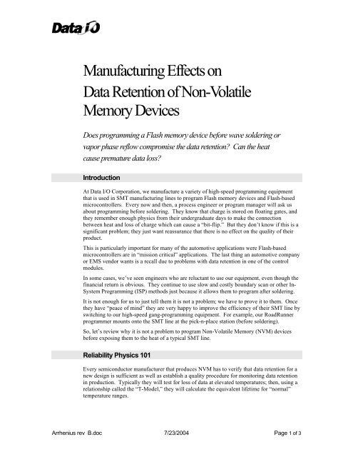
<str<strong>on</strong>g>Manufacturing</str<strong>on</strong>g> <str<strong>on</strong>g>Effects</str<strong>on</strong>g> <strong>on</strong><strong>Data</strong> Retenti<strong>on</strong> <strong>of</strong> N<strong>on</strong>-<strong>Volatile</strong><strong>Memory</strong> DevicesDoes programming a Flash memory device before wave soldering orvapor phase reflow compromise the data retenti<strong>on</strong>? Can the heatcause premature data loss?Introducti<strong>on</strong>At <strong>Data</strong> I/O Corporati<strong>on</strong>, we manufacture a variety <strong>of</strong> high-speed programming equipmentthat is used in SMT manufacturing lines to program Flash memory devices and Flash-basedmicroc<strong>on</strong>trollers. Every now and then, a process engineer or program manager will ask usabout programming before soldering. They know that charge is stored <strong>on</strong> floating gates, andthey remember enough physics from their undergraduate days to make the c<strong>on</strong>necti<strong>on</strong>between heat and loss <strong>of</strong> charge which can cause a “bit-flip.” But they d<strong>on</strong>’t know if this is asignificant problem; they just want reassurance that there is no effect <strong>on</strong> the quality <strong>of</strong> theirproduct.This is particularly important for many <strong>of</strong> the automotive applicati<strong>on</strong>s were Flash-basedmicroc<strong>on</strong>trollers are in “missi<strong>on</strong> critical” applicati<strong>on</strong>s. The last thing an automotive companyor EMS vendor wants is a recall due to problems with data retenti<strong>on</strong> in <strong>on</strong>e <strong>of</strong> the c<strong>on</strong>trolmodules.In some cases, we’ve seen engineers who are reluctant to use our equipment, even though thefinancial return is obvious. They c<strong>on</strong>tinue to use slow and costly boundary scan or other In-System Programming (ISP) methods just because it allows them to program after soldering.It is not enough for us to just tell them it is not a problem; we have to prove it to them. Oncethey have “peace <strong>of</strong> mind” they are very happy to improve the efficiency <strong>of</strong> their SMT line byswitching to our high-speed gang-programming equipment. For example, our RoadRunnerprogrammer mounts <strong>on</strong>to the SMT line at the pick-n-place stati<strong>on</strong> (before soldering).So, let’s review why it is not a problem to program N<strong>on</strong>-<strong>Volatile</strong> <strong>Memory</strong> (NVM) devicesbefore exposing them to the heat <strong>of</strong> a typical SMT line.Reliability Physics 101Every semic<strong>on</strong>ductor manufacturer that produces NVM has to verify that data retenti<strong>on</strong> for anew design is sufficient as well as establish a quality procedure for m<strong>on</strong>itoring data retenti<strong>on</strong>in producti<strong>on</strong>. Typically they will test for loss <strong>of</strong> data at elevated temperatures; then, using arelati<strong>on</strong>ship called the “T-Model,” they will calculate the equivalent lifetime for “normal”temperature ranges.Arrhenius rev B.doc 7/23/2004 Page 1 <strong>of</strong> 3
The T-Model is used because it takes into account both temperature and voltage effects. Thisis appropriate because the semic<strong>on</strong>ductor manufacturer is trying to determine the dataretenti<strong>on</strong> for NVM used in an applicati<strong>on</strong> where heat and power are applied at the same time.(An automotive applicati<strong>on</strong> is a good example where a NVM device is used at elevatedtemperatures.)The T-Model is defined as follows:⎡Tt−TAf = exp ⎢⎣ Tou⎤⎥⎦where A f is the accelerati<strong>on</strong> factor, T u is the temperature <strong>of</strong> the “normal” envir<strong>on</strong>ment, and T tis the elevated temperature where failures are induced at an accelerated rate. (Note both <strong>of</strong>these temperatures are in degrees Kelvin.) To is the characteristic temperature for dataretenti<strong>on</strong> that embodies dielectric, field strength, and charge loss effects. For EPROMs usingan oxide-nitride-oxide process, <strong>on</strong>e manufacturer empirically determined To to be 21°K forthe floating gate.To c<strong>on</strong>tinue the example, let's say we are trying to determine the data retenti<strong>on</strong> for anautomotive applicati<strong>on</strong> where a microc<strong>on</strong>troller (with embedded EPROM) sees a juncti<strong>on</strong>temperature <strong>of</strong> 125°C. For <strong>on</strong>e <strong>of</strong> the tests, we might measure data retenti<strong>on</strong> for over 450hours at 250°C. (Obviously, this is at wafer burn-in; the plastic encapsulent use in SMTpackages cannot withstand this temperature.) Using the T-Model, we would calculate theaccelerati<strong>on</strong> factor as follows:Af⎡523− 398⎤= exp⎢= 384⎣ 21 ⎥⎦An accelerati<strong>on</strong> factor <strong>of</strong> 384 means that if it lasted for 450 hours at 250°C, it will last 384times l<strong>on</strong>ger at 125°C, or about 20 years. This is certainly sufficient for any automotiveapplicati<strong>on</strong>.But when we think about our perennial questi<strong>on</strong> “Does the heat from reflow hurt the data?”,there is no voltage applied to the embedded Flash; the device is “<strong>of</strong>f.” So how do we modelthis?Well, if temperature effects al<strong>on</strong>e are what we are trying to model, then we can use thefamous Arrhenius relati<strong>on</strong>ship. This model describes the effect that temperature has <strong>on</strong> achemical process with a certain “activati<strong>on</strong> energy.” Like the T-Model, it produces anaccelerati<strong>on</strong> factor for a system exposed to an elevated temperature. The relati<strong>on</strong> is asfollows:Af⎡ E= exp ⎢⎣ ka⎛ 1⎜⎝ Tu1 ⎞⎤−⎟⎥Tt⎠⎦where A f is the accelerati<strong>on</strong> factor, E a is the activati<strong>on</strong> energy (in eV), k is Boltzman’sc<strong>on</strong>stant (in eV), T u is the temperature <strong>of</strong> the “normal” envir<strong>on</strong>ment, and T t is again theelevated temperature. (Again, these temperatures are in degrees Kelvin.)But in order to use the Arrhenius relati<strong>on</strong>ship, we need to empirically determine the“activati<strong>on</strong> energy” by fitting a curve to some experimental results at different temperatures.The activati<strong>on</strong> energy is a critical parameter for getting meaningful results. A typicalactivati<strong>on</strong> energy is 0.8 eV for effects related to charge loss when no voltage is applied to thedevice.So, for another example, say there is a guided muniti<strong>on</strong>s applicati<strong>on</strong> where an electr<strong>on</strong>icmodule might sit in storage in the desert. Assuming the internal temperature <strong>of</strong> the shellreaches 125°C, the customer wants to know if this will compromise the data retenti<strong>on</strong> in theArrhenius rev B.doc 7/23/2004 Page 2 <strong>of</strong> 3
embedded Flash. In this case, we would use data from a test where we measured dataretenti<strong>on</strong> at wafer burn-in with no power applied to the circuit (other than brief intervals toread the data and make sure it was still OK). So let’s assume we measured good retenti<strong>on</strong> forover 1000 hours at 250°C. (This is typical <strong>of</strong> today’s NVM.) Using the Arrheniusrelati<strong>on</strong>ship, we would calculate the accelerati<strong>on</strong> factor as follows:A f⎡ 0.8 ⎛ 1 1 ⎞⎤exp⎢= 2635⎜ − ⎟⎥⎣8.6171x 10 ⎝ 398 523⎠⎦=−So, with an accelerati<strong>on</strong> factor <strong>of</strong> 263, the data retenti<strong>on</strong> in the applicati<strong>on</strong> (at 125°C) will bemore than 263 x 1000 = 263,000 hours or over 30 years. (I’m sure the US Army would behappy with this result.)This same process can be applied to data retenti<strong>on</strong> effects from heat exposure duringsoldering. Peak temperatures <strong>of</strong> 235°C are typical, but the durati<strong>on</strong>s are much shorter. Let’suse the Arrhenius relati<strong>on</strong>ship to calculate how much <strong>of</strong> the “life” we are using up by heatinga NVM device after programming.SMT Reflow ExampleSay you are using vapor phase reflow with a peak temperature <strong>of</strong> 235°C at a durati<strong>on</strong> <strong>of</strong> 60sec<strong>on</strong>ds. The thermal pr<strong>of</strong>ile also includes ramping up to 125°C for a few minutes, but wehave already shown that there is negligible effect at this temperature.The worse case assumpti<strong>on</strong> would be that the thermal mass <strong>of</strong> the NVM device is so smallthat the die temperature is tracking the ambient temperature. Using the same data point as inthe previous example, we can calculate the accelerati<strong>on</strong> factor between n<strong>on</strong>-powered dataretenti<strong>on</strong> tests and the SMT vapor phase reflow temperature as follows:A f⎡ 0.8 ⎛ 1 1 ⎞⎤exp⎢= 1.695⎜ − ⎟⎥⎣8.6171x 10 ⎝ 508 523 ⎠⎦=−So now we are saying that there is very little difference between charge loss at 250°Ccompared to 235°C; <strong>on</strong>ly a factor <strong>of</strong> about 1.7. So if we spend 1 minute at 235°C, what havewe d<strong>on</strong>e to the average data retenti<strong>on</strong> time? To find out, just divide 1 minute by 1000 hourstimes 1.7. This turns out to be about 10 ppm or 0.001% <strong>of</strong> the calculated life.So, referring back to the guided muniti<strong>on</strong>s applicati<strong>on</strong>, the effect <strong>of</strong> programming before SMTreflow reduces the data retenti<strong>on</strong> lifetime from 30 years to 29.9997 years. So who cares?On most data sheets for SMT devices, there is a list <strong>of</strong> Absolute Maximum Ratings. Includedin these parameters is usually the maximum heat exposure this part can withstand duringsoldering and still be reliable. But this maximum rating is mostly due to the thermomechanicaleffects. For example, at extreme temperatures the encapsalent will flow and tear<strong>of</strong>f wire b<strong>on</strong>ds. But as we have shown, data retenti<strong>on</strong> is not a problem for this brief thermalexposure.Note that for a thorough estimate <strong>of</strong> reliability <strong>of</strong> a NVM device, we would also have toinclude thermo-mechanical effects and temperature-humidity effects.C<strong>on</strong>clusi<strong>on</strong>We have greatly simplified the reliability physics for NVM devices by just c<strong>on</strong>sidering chargeleakage at elevated temperatures in an unpowered device. But this is the appropriate modelbased <strong>on</strong> the questi<strong>on</strong> we are always asked. And now we have the answer – there is negligibleeffect <strong>on</strong> data retenti<strong>on</strong> by soldering NVM devices after they have been programmed.Arrhenius rev B.doc 7/23/2004 Page 3 <strong>of</strong> 3