RoadRunner Owner's Manual - Data I/O Corporation
RoadRunner Owner's Manual - Data I/O Corporation
RoadRunner Owner's Manual - Data I/O Corporation

You also want an ePaper? Increase the reach of your titles
YUMPU automatically turns print PDFs into web optimized ePapers that Google loves.
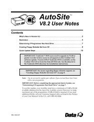
Seeseparate Service ManuCovers all models.Includes a fill-inmaintenance chart.OverviewInstallationOperationMaintenanceProLINE-<strong>RoadRunner</strong>Owner’s <strong>Manual</strong>TMTroubleshootGlossaryPN 096-0240-005HIndex
1 OverviewGeneral Descriptions • TaskLink • Safety Precautions • Specifications12 InstallationUnpack • Setup • Power Up23 OperationKeypad Operation • Menus • Programming • Yields • Updates3Order form for Service <strong>Manual</strong>(See separate Service <strong>Manual</strong> for:• Replacement Procedures • Basic Spare Parts • Self-Service Spare Parts • Order Forms)45 MaintenancePreventive Schedule • Diagnostics • Sign-off Chart56 TroubleshootingError Messages • Other Problems6GlossaryGIndexSales and Technical Support contact numbers are after the index.I
<strong>Data</strong> I/O has endeavored to ensure that the information in this document is accurate andcomplete. <strong>Data</strong> I/O assumes no liability for errors, or for any incidental, consequential,indirect, or special damages, including, without limitation, loss of use, loss or alterationof data, delays, or lost profits or savings, arising from the use of this document or theproduct which it accompanies.No part of this document may be reproduced or transmitted in any form or by anymeans, electronic or mechanical, for any purpose, without written permission from <strong>Data</strong>I/O <strong>Corporation</strong>. <strong>Data</strong> I/O order forms may be reproduced for internal use only.<strong>Data</strong> I/O is a registered trademark of <strong>Data</strong> I/O <strong>Corporation</strong>, as areProLINE‐<strong>RoadRunner</strong> and TaskLink.<strong>Data</strong> I/O <strong>Corporation</strong> acknowledges the trademarks of other organizations for theirrespective products or services mentioned in this document.The Technical Documentation Department also acknowledges the <strong>RoadRunner</strong> teammembers for their efforts in supporting the flow of information into this manual.We are interested in your comments. email: userdocs@dataio.com© 2004–2010 <strong>Data</strong> I/O <strong>Corporation</strong>All rights reserved
Contents096-0240-005H1 • Overview<strong>RoadRunner</strong> is — 1–1Warning and Caution Notes 1–3Overall System Description 1–4Development of the Programming Instructions for a Job 1–4Control Panel 1–5Blank Devices 1–5Tape Advancement 1–5Robotic System 1–6Programmer Module 1–8Output Conveyor 1–10Reject Bin 1–10TaskLink’s Handshake with <strong>RoadRunner</strong> 1–11PCMCIA Memory Card Capacity Requirements 1–11Safety 1–12Safety Features 1–12Precautions for Safe Operation 1–14Specifications [Assembleon] 1–15Specifications [Fuji QP, IP, XP] 1–16Specifications [Fuji NXT, AIM] 1–17Specifications [MYDATA] 1–18Specifications [Panasonic CM20, CM120, CM301] 1–19Specifications [Panasonic CM401, CM402, CM602, DT401] 1–20Specifications [Panasonic MSF, MCF, MPAV2B, MPAG3] 1–21Specifications [Siemens, XLF, SIPLACE X] 1–22Specifications [Universal GSM] 1–23Specifications [Universal Genesis] 1–24<strong>Data</strong> I/O • ProLINE-<strong>RoadRunner</strong> Owner’s <strong>Manual</strong> • 096-0240i
2 • InstallationUnpacking the <strong>RoadRunner</strong> 2–1Removing the Shipping Bracket 2–2Mounting the <strong>RoadRunner</strong> 2–3Mounting <strong>RoadRunner</strong> [Assembleon ACM] 2–4Mounting <strong>RoadRunner</strong> [MYDATA MY9, MY12, MY15, MY19] 2–6Mounting <strong>RoadRunner</strong> [Fuji QP242, QP351, IP3, XP142E] 2–8Mounting <strong>RoadRunner</strong> [Fuji NXT, AIM] 2–10Mounting <strong>RoadRunner</strong> [Panasonic MSF, MCF, MPA] 2–11Mounting <strong>RoadRunner</strong> [Panasonic CM20, CM120, CM301] 2–12Mounting <strong>RoadRunner</strong> [Panasonic CM401, CM402, DT] 2–14Mounting <strong>RoadRunner</strong> [Siemens 80F4, 80F5, F, S, HS] 2–17Mounting <strong>RoadRunner</strong> [Siemens SIPLACE X2, X3, X4, X4i] 2–20Mounting <strong>RoadRunner</strong> [Universal GSM1,GSM2, Genesis] 2–22Installing the Reject Bin 2–24Making the Necessary Connections 2–25Electrical Input Requirements 2–25Pneumatic Input Requirements 2–26Connecting the Communications Cable 2–28Applying Power for the First Time 2–30Turning Power On 2–30Configuring for Network Communication 2–31Configuring TaskLink 2–31Configuring <strong>RoadRunner</strong> 2–313 • OperationOperator Functions 3–1Basic Operator Steps 3–1Turning On System Power 3–2Menus Available to the System Operator 3–3Keypad Operation 3–4Setting Up <strong>RoadRunner</strong> for a Programming Job 3–5Programming Devices 3–18Miscellaneous Settings via the Menu 3–23Supervisor Functions 3–24Menus Available to the System Supervisor 3–24Setting Operational Parameters 3–27Setting System Parameters 3–31Network Settings 3–34Configuration 3–34Robot Diagnostics 3–35Programmer Diagnostics 3–36ii <strong>Data</strong> I/O • ProLINE-<strong>RoadRunner</strong> Owner’s <strong>Manual</strong> • 096-0240
Event Log 3–37Results 3–37Session <strong>Data</strong> Log 3–384 • Service information . . .. . . is in a separate manual, with its own Table of Contentsand Index. 4–15 • MaintenanceTools Required 5–1Preventive Maintenance Schedule 5–2Lubricating the Ball Screw 5–3Diagnosing with the Adapter Board 5–5Running Diagnostics on a Programmers 5–5Electrical Equipment Disposal Notice 5–7RoHS for China 5–7Maintenance Sign-off Charts 5–8Notes: 5–96 • TroubleshootingColored Lamp Significance 6–1Resolving Problems 6–2Testing the Programmer 6–2Viewing Errors 6–2Clearing Jammed Device Tape 6–2Disabling and Enabling a Socket 6–3Error Messages 6–4No Change in Lamps 6–4Yellow Lamp is On 6–4Blue Lamp is On 6–7Unlisted Error Messages 6–14Problems, but no Error Message 6–15Schematics 6–22Pneumatic Schematic 6–22Electrical Schematic 6–23<strong>Data</strong> I/O • ProLINE-<strong>RoadRunner</strong> Owner’s <strong>Manual</strong> • 096-0240iii
Glossary • Glossary of TermsAlphabetical List of Terms Glossary–1Index • IndexAlphabetical Index Listing Index–1iv <strong>Data</strong> I/O • ProLINE-<strong>RoadRunner</strong> Owner’s <strong>Manual</strong> • 096-0240
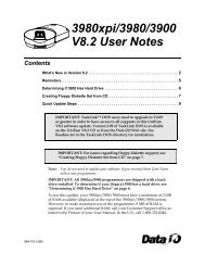
Chapter11Overview<strong>RoadRunner</strong> is —ProLINE-<strong>RoadRunner</strong> is a compact, portable, automatedprogramming and handling system that mounts directly to a Surface MountTechnology (SMT) Placement Machine. Easy to use and small enough to fitwithin the profile of a component feeder, the ProLINE-<strong>RoadRunner</strong> programsand delivers devices to the pick region of placement machines, allowingour customers to integrate device programming and placement.In this chapter you’lllearn about<strong>RoadRunner</strong>’s compact,component units calledmodules, safety precautions,ESD, and stoppingin an emergency. You canalso learn about the latestprogrammer architectureand High Force ConversionKits.<strong>RoadRunner</strong> is available for many different SMT Placement machines; someare shown on the next page. Other models for each SMT machine may alsoavailable, such as the <strong>RoadRunner</strong>-XLF (Extra Large Format). XLF<strong>RoadRunner</strong>s run devices up to 32 mm Wide x 32 mm Long x 6 mm High.The Standard <strong>RoadRunner</strong> programs devices up 21.65 mm W x 15 mm L x3mmH.TaskLinkThe Three Parts of a ProLINE-<strong>RoadRunner</strong> SystemPCMCIA Card<strong>RoadRunner</strong>Figure 1-1—The ProLINE-<strong>RoadRunner</strong> System is TaskLink Software,a Job Card, and the <strong>RoadRunner</strong> [Universal Model shown](Notebook PC not included.)<strong>Data</strong> I/O • ProLINE-<strong>RoadRunner</strong> Owner’s <strong>Manual</strong> • 096-0240 [updated Mar2010] 1—1
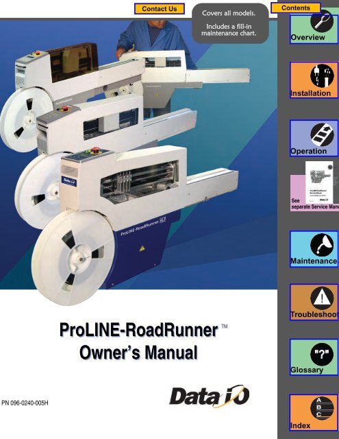
1Overview • <strong>RoadRunner</strong> is — ••Fuji QP, IPAssembleonXLF on Siemens F5SiemensFuji NXT, AIMUniversal GSMPanasonic MSFMYDATAPanasonic CM20Panasonic CM, DTFigure 1-2—Various Standard <strong>RoadRunner</strong>Models attached to corresponding SMTmachines and one XLF <strong>RoadRunner</strong>.1—2 <strong>Data</strong> I/O • ProLINE-<strong>RoadRunner</strong> Owner’s <strong>Manual</strong> • 096-0240 [updated Mar2010]
Warning and Caution NotesOverview • Warning and Caution Notes ••Special paragraphs in this manual warn about potentially hazardous situationsand recommend safe practices to help avoid them.1!A warning looks like this.Indicates conditions that can cause personalinjury or serious monetary loss.A caution looks like this.CAUTION: Indicates conditions that can cause damage to equipment.They are included to help the operator use the system safely and efficiently.Key to Symbols Used in this <strong>Manual</strong>General warning. Calls your attention to general caution andwarning notes.Electrostatic Discharge (ESD) may cause damage. Dischargestatic against a common ground.High voltage. Turn power off before removing electronicscover.Crush hazard. Keep hands away from moving parts.bCompressed air. Point air hoses away from body. Alwayswear approved eye protection.Heavy equipment. Use caution. May require two people. Or,mount properly using approved hardware.Equipment can tip over (such as feeder carts with some<strong>RoadRunner</strong>s on them). Remove <strong>RoadRunner</strong> before movingcart.Collision hazard.Some situations can cause machinery tocollide with object or people items are installed incorrectly.<strong>Data</strong> I/O • ProLINE-<strong>RoadRunner</strong> Owner’s <strong>Manual</strong> • 096-0240 [updated Mar2010] 1—3
1Overview • Overall System Description •• Development of the Programming Instructions for a JobOverall System DescriptionThe ProLINE-<strong>RoadRunner</strong> System consists of <strong>RoadRunner</strong> (which attachesto SMT Placement machines), TaskLink software for Windows-basedPCs, and a PCMCIA card (PC-Card). TaskLink is needed to create programmingjobs for <strong>RoadRunner</strong>. PC-Cards store jobs and contain job statistics.Using prepared programming instructions and blank devices, <strong>RoadRunner</strong>picks, programs, and delivers the devices to the pick region of an SMTPlacement machine.NOTE: This manual refers to the <strong>RoadRunner</strong>, TaskLink software,and a job card as the “ProLINE-<strong>RoadRunner</strong>,” or the“ProLINE-<strong>RoadRunner</strong> System.” The term “<strong>RoadRunner</strong>” then, isused to mean the hardware unit that attaches to the SMT placementmachine.Development of the Programming Instructions for aJobProgramming instructions are developed using TaskLink for Windows. ®The instructions are stored on PCMCIA Type I or II job cards that areformatted for <strong>RoadRunner</strong>.A <strong>RoadRunner</strong> operator can start a job by inserting a job card and pressingthe Start button on the control panel.StartFigure 1-3—The <strong>RoadRunner</strong> Control Panel and Display Screen1—4 <strong>Data</strong> I/O • ProLINE-<strong>RoadRunner</strong> Owner’s <strong>Manual</strong> • 096-0240 [updated Mar2010]
Control PanelOverview • Overall System Description •• Tape Advancement1The Control Panel is a keypad and display that provides a User Interface(UI) to the <strong>RoadRunner</strong> programming system.The main function of the Control Panel is to accept input (commands) fromthe operator via the keypad, while providing visual or auditory feedback tothe operator regarding status of the system.Blank DevicesBefore starting a job, the operator must mount a reel of tape containing blankdevices onto the <strong>RoadRunner</strong> or placement machine cart. Once the devicetape is threaded into the <strong>RoadRunner</strong> and a job is started, the <strong>RoadRunner</strong>will pick devices from the tape and advance the tape automatically.Periodically, new device tape must be loaded and the cover tape take-up reelmust be emptied.Tape AdvancementTape advancement includes three functions—advancing the device tape,separating the cover tape from the device tape, and collecting the cover tape.Tape-In ModuleA stepper motor drives a sprocket that advances the device tape viasprocket holes along the tape’s edge. Tape movement is stepped, allowingthe tape to stop each device directly under the pick point. The emptydevice tape is expelled at the front of the <strong>RoadRunner</strong> or near the frontbelow the conveyor. Different Tape-In Modules are available for differentwidth device tape, and there is an adjustable module that accommodates16, 24, and 32 mm tape.The XLF models also have an adjustable Tape-In Module that accommodates32 and 44 mm tape.Cover Tape ModuleThe Cover Tape Module winds up used cover tape so it can be disposed ofby the operator. A DC motor, synchronized with the tape advance motor,drives the Take-up Reel that winds up the separated cover tape. The covertape is threaded around a peel bar that separates it from the device tape.Some cover tape is sticky enough that it will affix directly to the reel, whileother cover tape must be fastened to the reel with a piece of adhesive tape.Refer to Figure .<strong>Data</strong> I/O • ProLINE-<strong>RoadRunner</strong> Owner’s <strong>Manual</strong> • 096-0240 [updated Mar2010] 1—5
Overview • Overall System Description •• Robotic System1PNP Head(& Cover–somemodels)Serial numberlabelProgrammerModuleLinear StageModuleFigure 1-5—PNP Head Positioned above Programming Sockets[Fuji Model Shown]Pick and Place HeadThe Pick and Place Head (PNP) is the portion of the robotic system responsiblefor picking, collecting, and placing devices. It houses four pneumaticcylinders, and four hollow probes for air flow. The pneumatic cylindersfeature spring return to the upper position. The probes incorporate a measureof compliance to allow contacting all sizes of devices without applyingexcessive force.The probes have rubber tips which must be kept clean in order to createadequate suction against the device.The PNP Assembly will not move until all four probes are in their up position.<strong>RoadRunner</strong> runs atslow speed when theRobotic Cover (safetyshield) is not in place.Linear StageA linear stage—consisting of a stepper motor, encoder and ball screw—moves the PNP head linearly to accommodate the following positions:• device tape pick point, • programmer sockets,• reject bin,• and programmer sockets.The linear stage motor receives signals from the motion controller via anamplifier. The PNP head is, itself, part of the Linear Stage Module.<strong>Data</strong> I/O • ProLINE-<strong>RoadRunner</strong> Owner’s <strong>Manual</strong> • 096-0240 [updated Mar2010] 1—7
1Overview • Overall System Description •• Programmer ModuleFigure 1-6—Pick and Place Assembly with Probes.Not shown: PNP Cover and the Precisor (XLF models do not use either).Vacuum ProbesThe rubber-tipped probes use vacuum produced by the Pneumatic Module topick up devices. The probes also deliver a puff of air to release the devices.Vacuum sensors detect whether a device is present at the end of each probe.Device Placement PrecisionOn standard <strong>RoadRunner</strong>s (not XLF), each probe brings its device intocontact with the alignment plate, called a precisor, to center the device on theprobe before placing it into a programming socket. Precisors are generallydevice-package specific.Programmer ModuleThe Programmer Module writes data into the devices. From a mechanicalstandpoint, it consists of device-specific sockets on an adapter and an actuator.The Programmer Module is responsible for:• opening the sockets• ID checking, blank-checking, continuity-checking and erasing thedevices, if selected• writing data to the devices• verifying the data written to devicesOpening the SocketsThe device sockets on the adapter are normally closed. To open the sockets,pneumatic cylinders pull the Actuator Plate down. Once the sockets areloaded they close again, keeping the device leads in contact with the socketpins.1—8 <strong>Data</strong> I/O • ProLINE-<strong>RoadRunner</strong> Owner’s <strong>Manual</strong> • 096-0240 [updated Mar2010]
Overview • Overall System Description •• Programmer ModuleHigh Force ActuationPrior to October 2007, four pneumatic cylinders were used to pull the ActuatorPlate down. Since 2007, and the introduction of our HIC Socket Adapters,more force is required. High Force Conversion Kits are availableallowing pre-2007 <strong>RoadRunner</strong>s to use HIC Adapters. (Later models actuateHIC Adapters without conversion kits.)1The following charts lists upgrade kits available for new programmers aswell as higher force actuation.Sales Part DescriptionRR-PROG MOD HF KIT FCIIRR-PROG HF UPGRADE KITRR-FCIII UPGRADE KITDescription–Upgrade to High Force FlashCORE II programmer.–Upgrade to High Force actuation only.–Upgrade to FlashCORE III programmers.FlashCORE II is the seconditeration of this programmingarchitecture. Contact<strong>Data</strong> I/O for FlashCOREUpgrade Kits.Programming DevicesThe <strong>RoadRunner</strong> programmer architecture, called FlashCORE, was developedspecifically for very high-speed programming of Flash memorydevices. Up to four devices are programmed simultaneously according to theinstructions from the particular job on the job card. Job cards must beprogrammed using TaskLink for Windows.In addition to programming the devices, the programmer can perform acontinuity check, a blank check, an electronic identification check, and adata verification. If any of these tests fail, the programmer illuminates thered LED in front of the socket(s) containing the failed device(s) and signalsthe robotic system to place the device into the reject bin rather than on theconveyor belt.Programming yield statistics are displayed on the screen. If a job is paused orended, the statistics are written to the job card.Programming sockets are a wear item, and therefore, must be replaced periodically.Socket manufacturers provide expected socket-insertion life cycles.See “Preventive Maintenance Schedule” on page 5-2 for recommendationsfor <strong>RoadRunner</strong>.<strong>Data</strong> I/O • ProLINE-<strong>RoadRunner</strong> Owner’s <strong>Manual</strong> • 096-0240 [updated Mar2010] 1—9
1Overview • Overall System Description •• Reject BinOutput ConveyorSuccessfully programmed devices are removed from the programmingsockets by the PNP Head and placed on the conveyor belt, then deliveredto the SMT Placement machine’s pick position.The conveyor module includes a conveyor belt, a sensor that determines ifdevices are at the SMT pick point, and in some models the path for theempty device tape. The conveyor runs momentarily when a job is started todetermine if there are any unwanted devices on the belt (from a previousjob). The belt stops when a device is sensed at the SMT machine pickpoint, when the robot places a new set of devices on the belt, or when ittimes out.Reject BinDevices that have failed programming, as determined by data verification,are dropped into a Reject Bin inside <strong>RoadRunner</strong>.The Reject Bin has a sensor that indicates when it is full by displaying amessage on the keypad screen; “Empty Reject Bin.”1—10 <strong>Data</strong> I/O • ProLINE-<strong>RoadRunner</strong> Owner’s <strong>Manual</strong> • 096-0240 [updated Mar2010]
Overview • TaskLink’s Handshake with <strong>RoadRunner</strong> •• PCMCIA Memory Card Capacity RequirementsTaskLink’s Handshake with <strong>RoadRunner</strong>TaskLink for Windows is the software program used to create programmerinstructions for the <strong>RoadRunner</strong> system. It consists of various utilities forselecting• the device to program,• the data file to write to the device, and• special programming options specific to the device.1NOTE: The term task refers to a device programming objectivebeing defined with TaskLink. The term job refers to a set of instructionsfor programming a specific number of devices with the<strong>RoadRunner</strong>.TaskLink must be installed on a Windows-based PC and configured to workwith the <strong>RoadRunner</strong> programmer.To install TaskLink, see the instructions on the CD.Parallel ATA-2 is aninterface standard for theconnection of storagedevices and uses a PCM-CIA form factor: 85.6 ×54 × 3.3 mm 68 pin dualrow connecting interface.A PCMCIA memory card drive capable of reading and writing to ParallelATA-2 specification must be available to the computer being used. For moreabout PCMCIA drives see “PCMCIA Memory Card Capacity Requirements”below.See TaskLink’s on-screen Help (for <strong>RoadRunner</strong>) to create a <strong>RoadRunner</strong>Job.PCMCIA Memory Card Capacity RequirementsProLINE-<strong>RoadRunner</strong> uses a 68 pin PCMCIA (PC) Card to transfer jobconfiguration and device programming data from TaskLink software(running on a PC) to <strong>RoadRunner</strong>. The PC Card is used to store job files,statistics/event log, algorithms, and even system updates.Ensure the card you use will hold your device image data plus 130 KB forstatistics and event files. The general formula used to calculate required PCcard size for one job;256 KB+device size+130 KBRemember that 1 MB = 1024 KB.In general, add 256 KB to device size (for system files). To calculate eachjob size, sum all jobs together and add 130 KB for statistics and event files.For example, when creating a card with two jobs, one for a 28F800 (1 MB)device and one for a 29LV160 (2 MB) device you would need:(256 KB+1024 KB)+(256 KB+2048 KB)+130 KB = 3714 KB = 3.8 MBUse a 4 MB minimum ATA card for this configuration.<strong>Data</strong> I/O • ProLINE-<strong>RoadRunner</strong> Owner’s <strong>Manual</strong> • 096-0240 [updated Mar2010] 1—11
1Overview • Safety •• Safety FeaturesNOTE: The system operator can only access a single job from thePCMCIA memory card. If there is more than one job on the card,then the last job selected by the system supervisor is the one used. Itis recommended that only one job be placed on each PC Card toavoid operator confusion.NOTE: <strong>Data</strong> I/O recommends that a 2 MB minimum card be usedfor even a single job.CAUTION: PCMCIA Cards for use with <strong>RoadRunner</strong>must be formatted with FAT 16. The current Windowsdefault is FAT 32. The card must be x40 speed.For information on card reader/writers that work with your computer systemand ProLINE-<strong>RoadRunner</strong>, see Card Reader/Writers on our Web site at:http://www.dataio.com/support/ and then:1. Click Knowledge Base Search.2. Sign in, or click Use the Knowledge Base without signing in.3. In the Keywords field, type Card Reader.4. Click Search.5. Click the document name to open it.SafetySafety FeaturesThe <strong>RoadRunner</strong> has several safety systems to reduce the likelihood ofpersonal injury and machine damage during operation. These systemsinclude:1. Safety Shields and InterlocksDuring <strong>RoadRunner</strong> operation the metal and plastic safety shield(Robotics Cover) covers the operating area to protect operators from1—12 <strong>Data</strong> I/O • ProLINE-<strong>RoadRunner</strong> Owner’s <strong>Manual</strong> • 096-0240 [updated Mar2010]
Overview • Safety •• Safety Features1injury. If the shield is opened, robot movement will reduce to halfspeed.!WARNINGRisk of injury. System robotics can injure yourhands or fingers. Do not operate the <strong>RoadRunner</strong>with covers removed. When working inside the<strong>RoadRunner</strong>, turn the power off.2. Emergency Stop Button (E-Stop)When the E-Stop button (located on the keypad) is pressed, the<strong>RoadRunner</strong> automatically removes power from all motion motors. Theblue status lamp illuminates, and the programmer completes its programmingcycle. The programmed devices will remain in their sockets.Figure 1-7—Emergency (movement) Stop Button!WARNINGShock hazard. Do not use the E-Stop button to turnoff power to the <strong>RoadRunner</strong>. The E-Stop buttondoes not completely remove power from themachine. Only power to the motion motors is shut off. Poweris still applied to all of the other electronic systems.CAUTION: The Emergency Stop button does not stop theSMT Placement equipment.The Emergency Stop condition will not be cleared until the E-Stop button isrestored to its run position. To restore the button to the run position, turn theEmergency Stop button clockwise until it springs back to its full height.<strong>Data</strong> I/O • ProLINE-<strong>RoadRunner</strong> Owner’s <strong>Manual</strong> • 096-0240 [updated Mar2010] 1—13
1Overview • Precautions for Safe Operation •• –Precautions for Safe OperationThe <strong>RoadRunner</strong> System has been designed for safe and efficient operation.The system can be dangerous if the <strong>RoadRunner</strong> safety features andprecautions in this manual are ignored.ElectrostaticDischargeThe circuit boards inside<strong>RoadRunner</strong> are susceptibleto electrostaticdischarge (ESD), whichcan damage the circuitry.Also, devices processedthrough the <strong>RoadRunner</strong>are very sensitive tostatic and can bedamaged by accidentalelectrostatic dischargewhile being handled.The easiest way toprevent damage fromESD is to make sure acommon static potential(ground) exists betweenstatic-sensitive devicesor components, theirenvironment, and theoperator.Perform all repairs at anESD-safe workstation.–To avoid possible personal injury or damage to the equipment, pleaseobserve the following practices:• Only trained personnel should install, maintain, repair, or troubleshootthis system.• Do not operate the ProLINE-<strong>RoadRunner</strong> unless you have been thoroughlytrained, and have read and understand the instructions in thismanual, particularly those that describe the system’s safety features.• Do not use ProLINE-<strong>RoadRunner</strong> for any application other than itsintended use.• Do not operate the system if the guards or safety devices are not intheir normal operating positions.• Do not operate <strong>RoadRunner</strong> with any of the outer sheet metal panelsremoved.• Do not operate <strong>RoadRunner</strong> while servicing, replacing, or adjusting anycomponent unless directed to do so in this manual. Make sure that the<strong>RoadRunner</strong> is properly shut down before performing any of theseoperations.• Do not place any part of your body near or in the direct path of movingparts.• Do not disable or attempt to defeat any of the protective safety featuresof this system. Personal injury or equipment damage can occur if anysafety systems on <strong>RoadRunner</strong> are disabled. If you suspect that a safetyfeature of the <strong>RoadRunner</strong> is damaged or malfunctioning, stop using the<strong>RoadRunner</strong> immediately and contact <strong>Data</strong> I/O Customer Service or alocal <strong>Data</strong> I/O approved service representative.• Use extra caution when working around the <strong>RoadRunner</strong>’s Output Belt.<strong>RoadRunner</strong>’s safety shields do not cover or fully enclose the outputconveyor. It is possible that an operator’s hands, other body parts, orloose clothing can get caught or pinched in it.• Wearing hearing protection is recommended while operating the<strong>RoadRunner</strong>. Sound pressure levels may exceed 85 decibels.• Shut off the pressurized air or disconnect the air hose before servicingpneumatic parts.1—14 <strong>Data</strong> I/O • ProLINE-<strong>RoadRunner</strong> Owner’s <strong>Manual</strong> • 096-0240 [updated Mar2010]
Specifications [Assembleon]Overview • Specifications [Assembleon] •• –1FACILITIESAC input voltage requirements 100-240 V~ ; 50/60 Hz (single phase)AC Input Power 100 W (max)Air requirements @ 2dm 3 /s (4.0scfm)Air Inlet tube (varies).52 MPa (75±2psi)6 mm (.24 in.) &8 mm (.31 in.) OD min.MODELS SUPPORTEDAssembleon models supported (with Assembleon UniversalAdapter)ACM, ACM Micro, AQ-1, AQ-2, D9DIMENSIONSWidthWeight (net)Length with 33 cm (13 in.) reelApproximate length protrudingfrom SMT machineHeight with 33 cm (13 in.) reel78 mm (3.1 in.)17 kg (38 lbs)124.5 cm (49 in.)63.5 cm (25 in.)49.5 cm (19.5 in.)Input tape width supported 16 mm; 24 mm; 32 mm (optional:12 mm, 32 mm-Large Format)DEVICE OUTPUT PLACEMENT(at SMT pick point)Output placement linear repeatability ±.25 mmOutput placement rotational repeatability ±5°ENVIRONMENTOperating temperature range 20–40°C (68–104°F)Temperature stabilization time after transportation ≥ 8 hHumidity 5–90%<strong>Data</strong> I/O • ProLINE-<strong>RoadRunner</strong> Owner’s <strong>Manual</strong> • 096-0240 [updated Mar2010] 1—15
1Overview • Specifications [Fuji QP, IP, XP] •• –Specifications [Fuji QP, IP, XP]FACILITIESAC input voltage requirements 100-240 V~ ; 50/60 Hz (single phase)AC Input Power 100 W (max)Air requirements @ 2dm 3 /s (4.0scfm)Air Inlet tube (varies).52 MPa (75±2 psi)6 mm (.24 in.) &8 mm (.31 in.) OD min.MODELS SUPPORTEDFuji models supportedQP242, IP3, QP351, XP142EDIMENSIONSWidth 78 mm (3.1 in.)Weight (net) 14 kg (32 lbs)Length with 33 cm (13 in.) reel 91.5 cm (36 in.)Approximate length protrudingfrom SMT machine0 cm (0 in.)Height with 33 cm (13 in.) reel 49 cm (19.5 in.)Input tape width supported 16 mm; 24 mm; 32 mm (optional:12 mm, 32 mm-Large Format)DEVICE OUTPUT PLACEMENT (at SMT pickpoint)Output placement linear repeatability ±.25 mmOutput placement rotational repeatability ±5°ENVIRONMENTOperating temperature range 20–40°C (68–104°F)Temperature stabilization time after transportation ≥ 8 hHumidity 5–90%1—16 <strong>Data</strong> I/O • ProLINE-<strong>RoadRunner</strong> Owner’s <strong>Manual</strong> • 096-0240 [updated Mar2010]
Specifications [Fuji NXT, AIM]Overview • Specifications [Fuji NXT, AIM] •• –1FACILITIESAC input voltage requirements 100-240 V~ ; 50/60 Hz (single phase)AC Input Power 100 W (max)Air requirements @ 2 dm 3 /s (4.0 scfm)Air Inlet tube.52 MPa (75±2 psi)8 mm (.31 in.) OD min.MODELS SUPPORTEDFuji models supportedNXT, AIMDIMENSIONSWidth 78 mm (3.1 in.)Weight (net) 17 kg (37 lbs)Length with 33 cm (13 in.) reelApproximate length protrudingfrom SMT machine104.4 cm (41.1 in)74 cm (29 in).Height with 33 cm (13 in.) reel 49 cm (19.5 in)Input tape width supported 16 mm; 24 mm; 32 mm (optional:12 mm, 32 mm-Large Format)DEVICE OUTPUT PLACEMENT (at SMT pickpoint)Output placement linear repeatability ±.25 mmOutput placement rotational repeatability ±5°ENVIRONMENTOperating temperature range 20–40°C (68–104°F)Temperature stabilization time after transportation ≥ 8 hHumidity 5–90%<strong>Data</strong> I/O • ProLINE-<strong>RoadRunner</strong> Owner’s <strong>Manual</strong> • 096-0240 [updated Mar2010] 1—17
1Overview • Specifications [MYDATA] •• –Specifications [MYDATA]FACILITIESAC input voltage requirementsAC Input PowerAir requirements @ 2dm 3 /s (4.0scfm)Air Inlet tube (varies)100-240 V~ ; 50/60 Hz (single phase)100 W (max).52 MPa (75±2 psi)6 mm (.24 in.) &8 mm (.31 in.) OD min.MODELS SUPPORTEDMYDATA models supportedMY9, MY12, MY15, MY19DIMENSIONSWidthWeight (net)Length with 33 cm reelApproximate length protruding from SMT Feeder Tableouter edgeHeightInput tape width supported78 mm (3.1 in.) without SMT Adapter16.5 kg (36.3 lbs) without SMT Adapter120.1 cm (47.3 in.) without SMT Adapter59.2 cm (23.3 in.) includes 33 cm reel49.4 cm (19.5 in.) includes 33 cm reel16 mm; 24 mm; 32 mm (optional:12 mm, 32 mm-Large Format)DEVICE OUTPUT PLACEMENT(at SMT pick point)Output placement linear repeatability±.25 mmOutput placement rotational repeatability ±5°ENVIRONMENTOperating temperature rangeTemperature stabilization time after transportation20–40°C (68–104°F)≥ 8 hHumidity 5–90%1—18 <strong>Data</strong> I/O • ProLINE-<strong>RoadRunner</strong> Owner’s <strong>Manual</strong> • 096-0240 [updated Mar2010]
Overview • Specifications [Panasonic CM20, CM120, CM301] •• –1Specifications [Panasonic CM20, CM120, CM301]FACILITIESAC input voltage requirements 100-240 V~ ; 50/60 Hz (single phase)AC Input Power 100 W (max)Air requirements at 2dm 3 /s (4.0scfm)Air Inlet tube.52 MPa (75±2 psi)8 mm (.31 in.) OD min.MODELS SUPPORTEDPanasonic models supportedCM20, CM120, CM301DIMENSIONSWidthWeight (net)Length with 33 cm (13 in.) reelApproximate length protrudingfrom SMT machine (including reel)Height with 33 cm (13 in.) reel7.8 cm (3.1 in.)14 kg (30.9 lbs)84 cm (33 in)61 cm (24 in)50 cm (19.7 in.)Input tape width supported 16 mm; 24 mm; 32 mm (optional:12 mm, 32 mm-Large Format)DEVICE OUTPUT PLACEMENT (at SMT pickpoint)Output placement linear repeatability ±.25 mmOutput placement rotational repeatability ±5°ENVIRONMENTOperating temperature range 20–40°C (68–104°F)Temperature stabilization time after transportation ≥ 8 hHumidity 5–90%<strong>Data</strong> I/O • ProLINE-<strong>RoadRunner</strong> Owner’s <strong>Manual</strong> • 096-0240 [updated Mar2010] 1—19
1Overview • Specifications [Panasonic CM401, CM402, CM602, DT401] •• –Specifications [Panasonic CM401, CM402, CM602, DT401]FACILITIESAC input voltage requirements 100-240 V~ ; 50/60 Hz (single phase)AC Input Power 100 W (max)Air requirements @ 2dm 3 /s (4.0scfm)Air Inlet tube.52 MPa (75±2 psi)8 mm (.31 in.) OD min.MODELS SUPPORTEDSiemens models supported CM401, CM402, CM602, DT401. APanasonic Feeder Bank Adapter andHost Feeder are required.DIMENSIONSWidth 7.8 cm (3.1 in.)Weight (net) 15 kg (33 lbs)Length without reel 99 cm (39 in.)Approximate length protrudingfrom SMT machine55 cm (21.6 in.)Height without reel 56 cm (22 in.)Input tape width supported 16 mm; 24 mm; 32 mm (optional:12 mm, 32 mm-Large Format)DEVICE OUTPUT PLACEMENT (at SMT pickpoint)Output placement linear repeatability ±.25 mmOutput placement rotational repeatability ±5°ENVIRONMENTOperating temperature range 20–40°C (68–104°F)Temperature stabilization time after transportation ≥ 8 hHumidity 5–90%1—20 <strong>Data</strong> I/O • ProLINE-<strong>RoadRunner</strong> Owner’s <strong>Manual</strong> • 096-0240 [updated Mar2010]
Overview • Specifications [Panasonic MSF, MCF, MPAV2B, MPAG3] •• –1Specifications [Panasonic MSF, MCF, MPAV2B, MPAG3]FACILITIESAC input voltage requirements 100-240 V~ ; 50/60 Hz (single phase)AC Input Power 100 W (max)Air requirements at 2dm 3 /s (4.0scfm)Air Inlet tube.52 MPa (75±2 psi)8 mm (.31 in.) OD min.MODELS SUPPORTEDPanasonic models supportedMSF, MPAV2B, MPAG3,MCFDIMENSIONSWidthWeight (net)Length with 33 cm (13 in.) reelApproximate length protrudingfrom SMT machineHeight with 33 cm (13 in.) reel78 mm (3.1 in.)16 kg (35 lbs)115 cm (45.25 in.)76 cm (30 in.)49.5 cm (19.5 in.)Input tape width supported 16 mm; 24 mm; 32 mm (optional: 12mm, 32 mm-Large Format)DEVICE OUTPUT PLACEMENT(at SMT pick point)Output placement linear repeatability ±.25 mmOutput placement rotational repeatability ±5°ENVIRONMENTOperating temperature range 20–40°C (68–104°F)Temperature stabilization time after transportation ≥ 8 hHumidity 5–90%<strong>Data</strong> I/O • ProLINE-<strong>RoadRunner</strong> Owner’s <strong>Manual</strong> • 096-0240 [updated Mar2010] 1—21
1Overview • Specifications [Siemens, XLF, SIPLACE X] •• –Specifications [Siemens, XLF, SIPLACE X]FACILITIESAC input voltage requirements 100-240 V~ ; 50/60 Hz (single phase)AC Input PowerAir requirements @ 2dm 3 /s (4.0scfm)Air Inlet tube (varies)100 W (max).52 MPa (75±2 psi)6 mm (.24 in.) &8 mm (.31 in.) OD min.MODELS SUPPORTEDSTD & XLF models supported SIPLACE X models supported model ——DIMENSIONS — model ——model ——WidthWeight (net)Length (unaffected by reel)Length including 33 cm reelLength including 33 cm reelApproximate length protruding from SMT FeederTable outer edgeHeightInput tape width supported• 80F4; 80F5, F, S, HF, HS Series*,DSeries*, X3*• SIPLACE X2, X3, X4, X4iStandardXLF modelsSIPLACE X78 mm (3.1 in.)99.5 mm (3.9 in.)78 mm (3.1 in.) (unaffected by SMT Adapter)15 kg (33 lbs)21 kg (45 lbs)19 kg (41 lbs) includes SMT Adapter99 cm (39 in.)118 cm (46.5 in.)120.1 cm (47.3 in.) includes SMT Adapter56 cm (22 in.)76.2 cm (30 in.) includes (33 cm) reel70.6 cm (27.8 in.) includes 33 cm reel56 cm (22 in.) (unchanged by reel)52 cm (20.5 in.) includes (33 cm) reel49.4 cm (19.5 in.) includes 33 cm reel16 mm, 24 mm, 32 mm (optional: 12 mm)16 mm, 24 mm, 32 mm, 44 mm (Opt: 12 mm)16 mm, 24 mm, 32 mm (optional: 12 mm)DEVICE OUTPUT PLACEMENT (at SMT pick point)Output placement linear repeatability±.25 mmOutput placement rotational repeatability ±5°ENVIRONMENTOperating temperature rangeTemperature stabilization time after transportation20–40°C (68–104°F)≥ 8 hHumidity 5–90%* Supported using S-type feeder table in feeder positions 2 & 4, except X3 in 4 only.1—22 <strong>Data</strong> I/O • ProLINE-<strong>RoadRunner</strong> Owner’s <strong>Manual</strong> • 096-0240 [updated Mar2010]
Specifications [Universal GSM]Overview • Specifications [Universal GSM] •• –1FACILITIESAC input voltage requirementsAC Input PowerAir requirements @ 2dm 3 /s (4.0scfm)Air Inlet tube (varies)100-240 V~ ; 50/60 Hz (single phase)100 W (max).52 MPa (75±2 psi)6 mm (.24 in.) &8 mm (.31 in.) OD min.MODELS SUPPORTEDUniversal models supportedGSM1; GSM2DIMENSIONSWidthWeight (net)Length with 33 cm (13 in.) reelApproximate length protrudingfrom SMT Placement machineHeight with 33 cm (13 in.) reelInput tape width supported78 mm (3.1 in.)17 kg (38 lbs)124. 5cm (49 in.)80.8 cm (31.8 in.)49.5 cm (19.5 in.)16 mm; 24 mm; 32 mm (optional:12 mm, 32 mm-Large Format)DEVICE OUTPUT PLACEMENT(at SMT pick point)Output placement linear repeatability±.25 mmOutput placement rotational repeatability ±5°ENVIRONMENTOperating temperature rangeTemperature stabilization time after transportation20–40°C (68–104°F)≥ 8 hHumidity 5–90%<strong>Data</strong> I/O • ProLINE-<strong>RoadRunner</strong> Owner’s <strong>Manual</strong> • 096-0240 [updated Mar2010] 1—23
1Overview • Specifications [Universal Genesis] •• –Specifications [Universal Genesis]FACILITIESAC input voltage requirements 100-240 V~ ; 50/60 Hz (single phase)AC Input Power 100 W (max)Air requirements @ 2dm 3 /s (4.0scfm)Air Inlet tube.52 MPa (75±2 psi)8 mm (.31in.) OD min.MODELS SUPPORTEDUniversal models supportedGenesisDIMENSIONSWidthWeight (net)Length with 33 cm (13 in.) reelApproximate length protrudingfrom SMT Placement machineHeight with 33 cm (13 in.) reel78 mm (3.1 in.18.2 kg (40 lbs)124. 5 cm (51.8 in.)72.1 cm (28.4 in.)49.5 cm (19.5 in.)Input tape width supported 16 mm; 24 mm; 32 mm (optional:12 mm, 32 mm-Large Format)DEVICE OUTPUT PLACEMENT(at SMT pick point)Output placement linear repeatability ±.25 mmOutput placement rotational repeatability ±5°ENVIRONMENTOperating temperature range 20–40°C (68–104°F)Temperature stabilization time after transportation ≥ 8 hHumidity 5–90%1—24 <strong>Data</strong> I/O • ProLINE-<strong>RoadRunner</strong> Owner’s <strong>Manual</strong> • 096-0240 [updated Mar2010]
Chapter22InstallationFor the Reject Bin locationsee Figure 19 on page 3-21or see “Reject Bin” in theService <strong>Manual</strong>.”Unpacking and installing the <strong>RoadRunner</strong> is easy. It is deliveredpreassembled with a few exceptions. There are four items that need tobe installed onto the <strong>RoadRunner</strong>: • the Socket Adapter, • Actuator Plate,• and Precisor (except on XLF models) that are described in Chapter 3,• and the Reject Bin which is described in this chapter. Some <strong>RoadRunner</strong>srequire an additional item to install to adapt it to the SMT machine. Theseare noted in the Mounting Instructions in this chapter where they apply. Allthat is required to operate the programmer is an SMT machine position andtwo external facilities. (You may also need to install some pneumatic componentsinto your air supply line.)!WARNINGLifting heavy objects improperly could injure you.The standard <strong>RoadRunner</strong> and shipping box weighs26 kg (58 lbs) maximum. The XLF model Road-Runner and box weighs 32 kg (70 lbs) maximum.This chapter includes:• Removing the Shipping Bracket• Proper mounting procedure for each model• Installing the Reject Bin• Pneumatic and Electrical requirements• Connecting the Communications Cable (applicable models)• Applying power• Setting the network configuration (optional).Unpacking the <strong>RoadRunner</strong>The <strong>RoadRunner</strong> is transported in an antistatic bag packaged in a heavy corrugatedbox with foam padding. On arrival, ensure that there is no damage tothe exterior of the box since this may also indicate damage to the machineinside. If there is significant damage to the box or shipping container, contactyour local <strong>Data</strong> I/O approved service representative immediately.<strong>Data</strong> I/O • ProLINE-<strong>RoadRunner</strong> Owner’s <strong>Manual</strong> • 096-0240 [updated Mar2010] 2—1
Installation • Removing the Shipping Bracket ••It takes about eight hours for the <strong>RoadRunner</strong> temperature to stabilize to thenew environment after shipping. Do not run a job before <strong>RoadRunner</strong> hasstabilized—the chassis should be at room temperature.2After opening the box containing the <strong>RoadRunner</strong>, inspect for damage thatmay have occurred during shipment. Two shock indicators have beenapplied to the shipping box for your assurance that the <strong>RoadRunner</strong> has notbeen mishandled during shipping. They are orange plastic indicators,2 inches (50.8 mm) long applied with adhesive backing. If the <strong>RoadRunner</strong>has sustained sufficient impact (25G) during shipment, the groove on eitherside of the label will be black or a color darker than the body color. SeeFigure 2-1. If this is the case, contact your local <strong>Data</strong> I/O Support Representativeimmediately. Both grooves the same color as the body indicate that noimpact has occurred.Figure 2-1—Shock Indicator is Indicating that an Impact has Occurred(Left Side, black arrow [
Installation • Mounting the <strong>RoadRunner</strong> ••Ball ScrewRail Hous-YellowShippingBracketTop ViewSideBall ScrewHeadCover(some2PNP HeadFigure 2-2—Shipping Bracket (Plan and Elevation Views)To remove the Shipping Bracket:1. Remove the Robotics Cover by grasping the outer edges and pulling.2. If your PNP head has a cover, remove the cover by pulling it straight offthe magnetized head bracket.3. Unscrew the socket head screw securing the Shipping Bracket to thePNP Head.4. Unscrew the two screws securing the Shipping Bracket to the BallScrew housing.5. Remove the Shipping Bracket.Mounting the <strong>RoadRunner</strong>The <strong>RoadRunner</strong> is designed to mount to the SMT machine feeder table.Multiple <strong>RoadRunner</strong>s may be mounted on the same SMT machine.CAUTION: Heavy weight. Use great care when mounting<strong>RoadRunner</strong> to the feeder table. It is heavy, and droppingit can cause serious damage to <strong>RoadRunner</strong> andanything it falls upon. Use only approved hardware tomount <strong>RoadRunner</strong> to the SMT feeder table.<strong>Data</strong> I/O • ProLINE-<strong>RoadRunner</strong> Owner’s <strong>Manual</strong> • 096-0240 [updated Mar2010] 2—3
Installation • Mounting the <strong>RoadRunner</strong> •• Mounting <strong>RoadRunner</strong> [Assembleon ACM]Mounting <strong>RoadRunner</strong> [Assembleon ACM]2Look ahead for mountinginstructions for yourspecific model of<strong>RoadRunner</strong>.NOTE: The Assembleon <strong>RoadRunner</strong> must be mounted to a UniversalFeeder Table Adapter. Install a Universal Feeder Table Adapteronto the ACM machine before continuing.Also, the ACM upper feeder guide must be used.NOTE: When selecting slot positions for<strong>RoadRunner</strong>, consider that access to it isfrom the right side.To mount the <strong>RoadRunner</strong> onto the SMT machine feeder bank, perform thefollowing:1. Hold the <strong>RoadRunner</strong> level and rest the nose on the feeder bank. Ensurethat the guide under the conveyor settles into a slot.Figure 2-3—Mounting the <strong>RoadRunner</strong> onto a Feeder Bank Changer.CAUTION: Feeder carts might become unstable. The<strong>RoadRunner</strong> can also be mounted on feeder carts andfeeder test stands. However, some carts/stands were notdesigned for the heavy overhang of the <strong>RoadRunner</strong> andmay tip over easily, especially if the wheels encounter bumps. Usecaution; don’t use (and do label) unsafe carts.2—4 <strong>Data</strong> I/O • ProLINE-<strong>RoadRunner</strong> Owner’s <strong>Manual</strong> • 096-0240 [updated Mar2010]
Installation • Mounting the <strong>RoadRunner</strong> •• Mounting <strong>RoadRunner</strong> [Assembleon ACM]2. Level the <strong>RoadRunner</strong> while continuing to support the weight, and slideit forward as far as it will go.3. Make sure the <strong>RoadRunner</strong> feels securely supported before letting go.It will latch to the feeder bank under its own weight.2Latch4. Check again that the <strong>RoadRunner</strong> is secure.Figure 2-4—Slide the <strong>RoadRunner</strong> ForwardThe <strong>RoadRunner</strong> is now mounted to the feeder bank.<strong>Data</strong> I/O • ProLINE-<strong>RoadRunner</strong> Owner’s <strong>Manual</strong> • 096-0240 [updated Mar2010] 2—5
Installation • Mounting the <strong>RoadRunner</strong> •• Mounting <strong>RoadRunner</strong> [MYDATA MY9, MY12, MY15, MY19]Mounting <strong>RoadRunner</strong> [MYDATA MY9, MY12, MY15,MY19]2CAUTION: Heavy weight. Use great care when mounting<strong>RoadRunner</strong> to the feeder table. It is heavy, anddropping it can cause serious damage to <strong>RoadRunner</strong>and anything it falls upon. Use only approved hardwareto mount <strong>RoadRunner</strong> to the SMT feeder table.To mount the Feeder Bank Adapter and <strong>RoadRunner</strong> onto a MYDATAMY-Series Assembly Machine:1. Slide the supplied Feeder Bank Adapter onto the assembly machinefeeder table at the desired slot. Push it forward as far as it will go.Figure 2-5—Install the Feeder Bank Adapter onto the SMT Machineseparately.2. Holding <strong>RoadRunner</strong> at a slight angle, slide it under the hook on theFeeder Bank Adapter so that the <strong>RoadRunner</strong> centering plate teethengage the pin next to the hook.pinhookTop View Into SMTFigure 2-6—Installing <strong>RoadRunner</strong> onto the Feeder Bank Adapter. A dowelon the Adapter (circled) mates with the <strong>RoadRunner</strong> nose.2—6 <strong>Data</strong> I/O • ProLINE-<strong>RoadRunner</strong> Owner’s <strong>Manual</strong> • 096-0240 [updated Mar2010]
Installation • Mounting the <strong>RoadRunner</strong> •• Mounting <strong>RoadRunner</strong> [Fuji QP242, QP351, IP3, XP142E]Mounting <strong>RoadRunner</strong> [Fuji QP242, QP351, IP3, XP142E]2CAUTION: Heavy weight. Use great care when mounting<strong>RoadRunner</strong> to the feeder table. It is heavy, anddropping it can cause serious damage to <strong>RoadRunner</strong>and anything it falls upon. Use only approved hardwareto mount <strong>RoadRunner</strong> to the SMT feeder table.To mount the <strong>RoadRunner</strong> onto the Multi-Feeder Unit (MFU), complete thefollowing procedure:1. Align and push the communications cable into a connector in the MFU.NOTE: When selecting slot positions for<strong>RoadRunner</strong>, consider that access to it isfrom the right side.Figure 2-9—The Communications Cable is inserted into the MFU.NOTE: The assembly machine pick point will correspond with theMFU slot number that is in-line with the conveyor belt. Make sureconveyor belt is closest to the slot number that the communicationcable is plugged into.2. Hold the <strong>RoadRunner</strong> at a slight nose-down angle and rest the nose onthe feeder bank. Ensure that the guide under the conveyor settles into aslot by pushing the <strong>RoadRunner</strong> gently to one side until you feel resistance.2—8 <strong>Data</strong> I/O • ProLINE-<strong>RoadRunner</strong> Owner’s <strong>Manual</strong> • 096-0240 [updated Mar2010]
Installation • Mounting the <strong>RoadRunner</strong> •• Mounting <strong>RoadRunner</strong> [Fuji QP242, QP351, IP3, XP142E]2Figure 2-10—The <strong>RoadRunner</strong> mounted onto a Multi Feeder Unit (MFU)CAUTION: Feeder carts might become unstable.<strong>RoadRunner</strong> can also be mounted on feeder carts andfeeder test stands. However, some carts/stands were notdesigned for the heavy overhang of <strong>RoadRunner</strong> andmay tip over easily, especially if the wheels encounter bumps. Usecaution; don’t use (and do label) unsafe carts.3. Slide <strong>RoadRunner</strong> forward until it comes to a solid stop. The nose willfit under the lip on the MFU.4. Lower <strong>RoadRunner</strong> fully to ensure that the steel angle under the conveyorsettles into the spring clamp on the MFU.SpringClampFigure 2-11—The angle bracket on <strong>RoadRunner</strong> fits into the MFU SpringClamp.5. Ensure that <strong>RoadRunner</strong> is secure.<strong>RoadRunner</strong> is now mounted to the Fuji MFU.<strong>Data</strong> I/O • ProLINE-<strong>RoadRunner</strong> Owner’s <strong>Manual</strong> • 096-0240 [updated Mar2010] 2—9
Installation • Mounting the <strong>RoadRunner</strong> •• Mounting <strong>RoadRunner</strong> [Fuji NXT, AIM]Mounting <strong>RoadRunner</strong> [Fuji NXT, AIM]2CAUTION: Heavy weight. Use great care when mounting<strong>RoadRunner</strong> to the feeder table. It is heavy, anddropping it can cause serious damage to <strong>RoadRunner</strong>and anything it falls upon. Use only approved hardwareto mount <strong>RoadRunner</strong> to the SMT feeder table.To mount <strong>RoadRunner</strong> onto a Feeder Table:NOTE: When selecting slot positionsfor <strong>RoadRunner</strong>, consider that access toit is from the right side.Also, do not use the four left-most slotson the table or the two right-most slots.1. Hold <strong>RoadRunner</strong>, one hand in the handhold and one under the Conveyor,so the Conveyor overlaps the Feeder Table by 40 mm and isabove a slot.Figure 2-12—Mounting <strong>RoadRunner</strong> onto the SMT Feeder Table.2. Lower <strong>RoadRunner</strong> allowing the nose to rest on the Feeder Table.Ensure that it settles into a slot.3. Still holding the handhold, slide <strong>RoadRunner</strong> forward as far as it willgo. <strong>RoadRunner</strong> locks into place.2—10 <strong>Data</strong> I/O • ProLINE-<strong>RoadRunner</strong> Owner’s <strong>Manual</strong> • 096-0240 [updated Mar2010]
Installation • Mounting the <strong>RoadRunner</strong> •• Mounting <strong>RoadRunner</strong> [Panasonic MSF, MCF, MPA]Mounting <strong>RoadRunner</strong> [Panasonic MSF, MCF, MPA]CAUTION: Heavy weight. Use great care when mounting<strong>RoadRunner</strong> to the feeder table. It is heavy, anddropping it can cause serious damage to <strong>RoadRunner</strong>and anything it falls upon. Use only approved hardwareto mount <strong>RoadRunner</strong> to the SMT feeder table.2NOTE: When selecting slot positions for<strong>RoadRunner</strong>, consider that access to it isfrom the right side.To mount <strong>RoadRunner</strong> for Panasonic onto a feeder cart:1. While holding <strong>RoadRunner</strong> level, let the nose rest on the cart. Line upthe hook with a slot.Figure 2-13—Mounting <strong>RoadRunner</strong> onto a feeder cart.2. Slide <strong>RoadRunner</strong> forward as far as it will go.The communication path will connect automatically.3. Ensure that <strong>RoadRunner</strong> is secure.<strong>Data</strong> I/O • ProLINE-<strong>RoadRunner</strong> Owner’s <strong>Manual</strong> • 096-0240 [updated Mar2010] 2—11
Installation • Mounting the <strong>RoadRunner</strong> •• Mounting <strong>RoadRunner</strong> [Panasonic CM20, CM120, CM301]Mounting <strong>RoadRunner</strong> [Panasonic CM20, CM120, CM301]2CAUTION: Heavy weight. Use great care when mounting<strong>RoadRunner</strong> to the feeder bank. It is heavy, anddropping it can cause serious damage to <strong>RoadRunner</strong>and anything it falls upon. Use only approved hardwareto mount <strong>RoadRunner</strong> to the SMT feeder bank.NOTE: When selecting slotpositions for <strong>RoadRunner</strong>, considerthat access to it is fromthe right side.Also, on STM machine CM20make sure the <strong>RoadRunner</strong>does not interfere with the handleon the machine cover.To mount <strong>RoadRunner</strong> onto the Feeder Bank:1. Hold <strong>RoadRunner</strong> at slight nose-down angle and rest the nose on thefeeder bank.2. Align the nose with a slot on the feeder bank. Ensure <strong>RoadRunner</strong>engages with one of the slots and the corresponding pin/rib as you pushforward.3. When it stops going forward push down on the <strong>RoadRunner</strong> to engagethe rollers on the bottom of the conveyor into the groove on the bank.See the figure below.RollersFigure 2-14—Rollers on the bottom of the Conveyor Module fit into thegroove on the feeder bank.4. Check that the <strong>RoadRunner</strong> is stable by rocking it cautiously.2—12 <strong>Data</strong> I/O • ProLINE-<strong>RoadRunner</strong> Owner’s <strong>Manual</strong> • 096-0240 [updated Mar2010]
Installation • Mounting the <strong>RoadRunner</strong> •• Mounting <strong>RoadRunner</strong> [Panasonic CM20, CM120, CM301]2Figure 2-15—<strong>RoadRunner</strong>/Panasonic mounted on the Feeder Bank.To remove the <strong>RoadRunner</strong>, lift up on the operator end and pull back out ofthe SMT machine.<strong>Data</strong> I/O • ProLINE-<strong>RoadRunner</strong> Owner’s <strong>Manual</strong> • 096-0240 [updated Mar2010] 2—13
Installation • Mounting the <strong>RoadRunner</strong> •• Mounting <strong>RoadRunner</strong> [Panasonic CM401, CM402, DT]Mounting <strong>RoadRunner</strong> [Panasonic CM401, CM402, DT]2CAUTION: Heavy weight. Use great care when mounting<strong>RoadRunner</strong> to the feeder bank. It is heavy, anddropping it can cause serious damage to <strong>RoadRunner</strong>and anything it falls upon. Use only approved hardwareto mount <strong>RoadRunner</strong> to the SMT feeder bank.NOTE: When selecting slot positions for<strong>RoadRunner</strong>, consider that access to it is fromthe right side.A Panasonic Feeder Bank Adapter and Host Feeder unit must be mounted tothe SMT Feeder Bank prior to mounting the <strong>RoadRunner</strong>. Then the Road-Runner can be mounted onto the Adapter. The steps for connecting the communicationcable follow.To mount the Feeder Bank Adapter and Host Feeder:1. Align the Feeder Bank Adapter with the numbered feeder slots and slideit forward to engage the alignment features. Push the Feeder BankAdapter forward as far as it will go.2. Tighten the set screw to lock in place. See Figure 2-16.3. Slide the Host Feeder onto the feeder slot immediately left of the FeederBank Adapter.Mounting andAlignment features:HookDowelSet screwFigure 2-16—Panasonic Feeder Bank Adapter and Host Feeder mountedon the CM402 SMT Feeder Bank4. Push the Host Feeder forward as far as it will go.2—14 <strong>Data</strong> I/O • ProLINE-<strong>RoadRunner</strong> Owner’s <strong>Manual</strong> • 096-0240 [updated Mar2010]
Installation • Mounting the <strong>RoadRunner</strong> •• Mounting <strong>RoadRunner</strong> [Panasonic CM401, CM402, DT]To mount <strong>RoadRunner</strong> onto the Panasonic Feeder Bank Adapter:1. Slide <strong>RoadRunner</strong> under the hook on the Feeder Bank Adapter so thatthe <strong>RoadRunner</strong> centering plate teeth engage the pin next to the hook.See Figure 2-17.2<strong>RoadRunner</strong> CenteringPlateFigure 2-17—The Panasonic Feeder Bank Adapter has a hook and a pin.2. Lower <strong>RoadRunner</strong> so that the Feeder Bank Adapter dowel mates withthe guide bushing on the <strong>RoadRunner</strong> conveyor. See Figure 2-18.Figure 2-18—The dowel on the Adapter (circled) mates with Roadrunner.3. Verify that <strong>RoadRunner</strong> is secure.To connect the Communication Cable into the HostFeeder:1. Correctly orient the connector (the red dot will be on top) and plug itinto <strong>RoadRunner</strong>. The socket is located on the back side—facing theSMT feeder table.2. Orient and plug the other end of the cable into the Host Feeder.3. Screw in the two connector screws. See Figure 2-19.<strong>Data</strong> I/O • ProLINE-<strong>RoadRunner</strong> Owner’s <strong>Manual</strong> • 096-0240 [updated Mar2010] 2—15
Installation • Mounting the <strong>RoadRunner</strong> •• Mounting <strong>RoadRunner</strong> [Panasonic CM401, CM402, DT]2Figure 2-19—<strong>RoadRunner</strong> is mounted and the Communication Cable isplugged into the Panasonic Host Feeder unit.2—16 <strong>Data</strong> I/O • ProLINE-<strong>RoadRunner</strong> Owner’s <strong>Manual</strong> • 096-0240 [updated Mar2010]
Installation • Mounting the <strong>RoadRunner</strong> •• Mounting <strong>RoadRunner</strong> [Siemens 80F4, 80F5, F, S, HS]Mounting <strong>RoadRunner</strong> [Siemens 80F4, 80F5, F, S, HS]CAUTION: Heavy weight. Use great care when mounting<strong>RoadRunner</strong> to the feeder table. It is heavy, anddropping it can cause serious damage to <strong>RoadRunner</strong>and anything it falls upon. Use only approved hardwareto mount <strong>RoadRunner</strong> to the SMT feeder table.2NOTE: When selecting slot positions for<strong>RoadRunner</strong>, consider that access to it isfrom the right side.To mount the <strong>RoadRunner</strong> onto the machine feeder table, perform the following:CAUTION: There are different hooks. Use of the wrong hook willcause mounting and device pick problems. Use the hook with blackknob or the hook with the Hex socket screw as shown on the labellocated on the <strong>RoadRunner</strong> Conveyor. You might also have a blackhook which is for the taller, later model of <strong>RoadRunner</strong>. The newHex-socket screw hook and the black anodized hook are interchangeable.1. Slide the proper mounting hook around a pin on the feeder table wherethe <strong>RoadRunner</strong> is to be mounted. Refer to Figures 2-20, 2-21, 2-22,and 2-23 for placement details.<strong>Data</strong> I/O • ProLINE-<strong>RoadRunner</strong> Owner’s <strong>Manual</strong> • 096-0240 [updated Mar2010] 2—17
Installation • Mounting the <strong>RoadRunner</strong> •• Mounting <strong>RoadRunner</strong> [Siemens 80F4, 80F5, F, S, HS]2Latest HookHook for early <strong>RoadRunner</strong>sFigure 2-20—Positioning the <strong>RoadRunner</strong>Mounting Hook—ensure the correct hook is used.Figure 2-21—The Hex socket-screw-hook for taller <strong>RoadRunner</strong>s[Siemens].Edge of<strong>RoadRunner</strong><strong>RoadRunner</strong>teethMount- into SMTRoadRun-AlignmentPlateFigure 2-22—Hook Location Relative to standard <strong>RoadRunner</strong> Placement.(not XLF models). Top View2—18 <strong>Data</strong> I/O • ProLINE-<strong>RoadRunner</strong> Owner’s <strong>Manual</strong> • 096-0240 [updated Mar2010]
Installation • Mounting the <strong>RoadRunner</strong> •• Mounting <strong>RoadRunner</strong> [Siemens 80F4, 80F5, F, S, HS]Edge of<strong>RoadRunner</strong><strong>RoadRunner</strong>teethMount- into SMT2<strong>RoadRunner</strong>HookAlignmentPlateFigure 2-23—Hook Location Relative to <strong>RoadRunner</strong>-Siemens XLFPlacement. Top view.!WARNING<strong>RoadRunner</strong> is heavy and can fall if the correctmounting hook is not properly attached. Fallingcan injure you or damage <strong>RoadRunner</strong>. The hookis absolutely required. Do not attempt to mount<strong>RoadRunner</strong> onto the feeder table without the hook installedonto the table.2. Tighten the hook thumbscrew or the 3 mm socket-head adjustmentscrew, as applicable.3. Slide <strong>RoadRunner</strong> under the hook so that the teeth engage the pin nextto the hook as shown in Figure 2-22 and below in Figure 2-24.Teeth on<strong>RoadRunner</strong>SiemensFigure 2-24—Early model Siemens <strong>RoadRunner</strong> Mounted onto the SMTFeeder Table [Siemens]4. Test to ensure <strong>RoadRunner</strong> is secure.<strong>RoadRunner</strong> is now mounted to the SMT feeder table.<strong>Data</strong> I/O • ProLINE-<strong>RoadRunner</strong> Owner’s <strong>Manual</strong> • 096-0240 [updated Mar2010] 2—19
Installation • Mounting the <strong>RoadRunner</strong> •• Mounting <strong>RoadRunner</strong> [Siemens SIPLACE X2, X3, X4, X4i]Mounting <strong>RoadRunner</strong> [Siemens SIPLACE X2, X3, X4, X4i]2CAUTION: Heavy weight. Use great care when mounting<strong>RoadRunner</strong> to the feeder table. It is heavy, anddropping it can cause serious damage to <strong>RoadRunner</strong>and anything it falls upon. Use only approved hardwareto mount <strong>RoadRunner</strong> to the SMT feeder table.!WARNINGFEEDER CARTS CAN TIP causing personal injury ordamage. Remove <strong>RoadRunner</strong> from the FeederCart before pulling the cart away from the SMTmachine.NOTE: When selecting slot positions for<strong>RoadRunner</strong>, consider that access to it isfrom the right side.NOTE: The SMT Adapter forSIPLACE X <strong>RoadRunner</strong> mustbe attached to <strong>RoadRunner</strong>before being mounting onto aFeeder Bank.If the SMT Adapter is notattached to the <strong>RoadRunner</strong>,contact <strong>Data</strong> I/O support— attaching it requires removing the<strong>RoadRunner</strong> Conveyor Cover.To mount the <strong>RoadRunner</strong> onto the machine feeder table, perform the following:1. Holding <strong>RoadRunner</strong> level, align the grooves on the Adapter with ribson the Feeder Bank, and slide <strong>RoadRunner</strong> as far forward as it will go.2—20 <strong>Data</strong> I/O • ProLINE-<strong>RoadRunner</strong> Owner’s <strong>Manual</strong> • 096-0240 [updated Mar2010]
Installation • Mounting the <strong>RoadRunner</strong> •• Mounting <strong>RoadRunner</strong> [Siemens SIPLACE X2, X3, X4, X4i]2Figure 2-25—The SMT Adapter on SIPLACE X <strong>RoadRunner</strong> mates with ribson the Feeder Bank.2. Make sure that the SMT latches onto the <strong>RoadRunner</strong>, and that<strong>RoadRunner</strong> is secure.Connect the communications cable (described in “Siemens SIPLACE XSeries Communications” on page 2-29).Remember to remove <strong>RoadRunner</strong> from the Feeder Cart prior to removingthe Feeder Cart from the SIPLACE Machine.<strong>Data</strong> I/O • ProLINE-<strong>RoadRunner</strong> Owner’s <strong>Manual</strong> • 096-0240 [updated Mar2010] 2—21
Installation • Mounting the <strong>RoadRunner</strong> •• Mounting <strong>RoadRunner</strong> [Universal GSM1,GSM2, Genesis]Mounting <strong>RoadRunner</strong> [Universal GSM1,GSM2, Genesis]2CAUTION: Heavy weight. Use great care when mounting<strong>RoadRunner</strong> to the feeder table. It is heavy, anddropping it can cause serious damage to <strong>RoadRunner</strong>and anything it falls upon. Use only approved hardwareto mount <strong>RoadRunner</strong> to the SMT feeder tableTo mount the <strong>RoadRunner</strong> onto the Universal machine feeder bank, performthe following:!WARNINGCollision hazard. If mounted incorrectly, the GSMpick head might collide with <strong>RoadRunner</strong>. For thisreason <strong>Data</strong> I/O recommends mounting<strong>RoadRunner</strong> only on the front feeder banks near Beam-2.If <strong>RoadRunner</strong> is mounted on banks 3 and 4 (the rear feederbanks), ensure that the feeder bank is in the outbound positiononly and NOT in the inbound or double inbound positions.Do NOT remove the GSM CE Cover that covers the upper halfof the GSM feeder bank opening.NOTE: When selecting slot positions for<strong>RoadRunner</strong>, consider that access to it isfrom the right side.1. Hold the <strong>RoadRunner</strong> level and rest the nose on the feeder bank. Ensurethat the guide under the conveyor settles into a slot.2—22 <strong>Data</strong> I/O • ProLINE-<strong>RoadRunner</strong> Owner’s <strong>Manual</strong> • 096-0240 [updated Mar2010]
Installation • Mounting the <strong>RoadRunner</strong> •• Mounting <strong>RoadRunner</strong> [Universal GSM1,GSM2, Genesis]2Figure 2-26—Mounting <strong>RoadRunner</strong> onto a Feeder Bank Changer.CAUTION: Feeder carts can become unstable. <strong>RoadRunner</strong> canalso be mounted on feeder carts and feeder test stands. However,some carts/stands were not designed for the heavy overhang of<strong>RoadRunner</strong> and may tip over easily, especially if the wheelsencounter bumps. Use caution; don’t use (and do label) unsafecarts.2. Level <strong>RoadRunner</strong> while continuing to support the weight, and slide itforward as far as it will go.3. If <strong>RoadRunner</strong> feels securely supported, let go.Its own weight will cause it to latch to the feeder bank.LatchFigure 2-27—Slide the <strong>RoadRunner</strong> Forward4. Cautiously rock <strong>RoadRunner</strong> to ensure that it is secure.<strong>RoadRunner</strong> is now mounted to the feeder bank.<strong>Data</strong> I/O • ProLINE-<strong>RoadRunner</strong> Owner’s <strong>Manual</strong> • 096-0240 [updated Mar2010] 2—23
Installation • Installing the Reject Bin •• —2Installing the Reject Bin—The Reject Bin may not be in place when you receive your <strong>RoadRunner</strong>.When it is in place, it sits between the beginning of the Conveyor and the<strong>RoadRunner</strong> chassis.NOTE: The Reject Bin for a Standard <strong>RoadRunner</strong> does not fit intoa <strong>RoadRunner</strong> XLF (Extra Large Format).Figure 2-28—The Reject Bin. (The Reject Bin for the <strong>RoadRunner</strong> XLFlooks slightly different.)To install the Reject Bin, hold the small, channel-shaped chute with thumband forefinger like you might hold a movie ticket. With the chamber horizontal,move the bin straight over the conveyor and just under the black LinearStage until it stops against the chassis. Lower it as far as it will go.CAUTION: The PNP Head might collide with the Reject Bin if theReject Bin is not installed properly. You can test the clearance bypushing the E-Stop and then manually pushing the PNP Head overto the Reject Bin.NOTE: <strong>RoadRunner</strong> will not function without the Reject Bin inplace.2—24 <strong>Data</strong> I/O • ProLINE-<strong>RoadRunner</strong> Owner’s <strong>Manual</strong> • 096-0240 [updated Mar2010]
Installation • Making the Necessary Connections •• Electrical Input RequirementsMaking the Necessary ConnectionsThe <strong>RoadRunner</strong> requires only two external facilities: electrical AC powerand standard shop pressurized air. The specific requirements are statedbelow as well as on labels inside the <strong>RoadRunner</strong>. Refer to Figure 2-29 forfacility connection locations.AssembleonACMSiemens 80F, S,HS Series,DSeries &Pansonic CM401,CM402, DT4012EEEEXLF modelSiemens 80F, S,HS Series, D SeriesEFuji QP242,QP351, IP3EFuji NXT & AIM,Panasonic MSF,MCF, MPA,Universal GSM,GenesisSIPLACE X-Series, MYDATAMY Series=AC Power ◦=Air Fitting E=Ethernet =CommunicationsFigure 2-29—<strong>RoadRunner</strong> Facilities Connection Points.For models where no Communication Connection is indicated, theconnection is on the far side (not visible here).Electrical Input RequirementsThe <strong>RoadRunner</strong> uses 100-240VAC, 50/60Hz, single phase power. Therequired power is supplied through a single connection on the <strong>RoadRunner</strong>’send panel. <strong>RoadRunner</strong> uses a standard IEC-320-C13 power cord. Thepower supply is self-regulating, and requires no special settings for regionalpower requirements.<strong>Data</strong> I/O • ProLINE-<strong>RoadRunner</strong> Owner’s <strong>Manual</strong> • 096-0240 [updated Mar2010] 2—25
Installation • Making the Necessary Connections •• Pneumatic Input RequirementsPower is applied to the internal systems of the <strong>RoadRunner</strong> when the powerswitch is ON. All power is removed when the power switch is OFF.2!WARNINGElectrical shock hazard. If the main power switch isON, power is applied to the electronic systems of<strong>RoadRunner</strong>, regardless of the position of the Emergency-Stopbutton or safety shield. Always turn the mainpower switch OFF before working inside the machine.Pneumatic Input Requirements<strong>RoadRunner</strong> requires a pressurized air source connected to the<strong>RoadRunner</strong>’s end panel. <strong>RoadRunner</strong> requires clean, dry, oil-free air, atapproximately 5.17 Bars (517 kPa) (75 psi) from an industrial grade compressor.The compressor tank should be of sufficient volume to maintainconstant air pressure at a minimum of 113 Liters/minute (4 cubic feet/minute).A 10 micron filter/separator/regulator must be installed betweenthe compressor and the <strong>RoadRunner</strong> to extract any contaminants andmoisture before the air enters the machine.Pneumatic Regulator KitProper operation of <strong>RoadRunner</strong> on SMT machines is accomplished byinstalling a <strong>Data</strong> I/O Regulator Kit. The kit ensures consistent air pressureand is required for proper <strong>RoadRunner</strong> operation.Check with <strong>Data</strong> I/O for your kit availability and installation instructions.The Regulator Kit Model Name (for ordering) for Assembleon Fuji, Panasonic,and Universal is RR-REGULATOR KIT-UF.Figure 2-30—Regulator Kit for Placement Machines(Instructions for <strong>RoadRunner</strong>/Siemens are listed below.)2—26 <strong>Data</strong> I/O • ProLINE-<strong>RoadRunner</strong> Owner’s <strong>Manual</strong> • 096-0240 [updated Mar2010]
Installation • Making the Necessary Connections •• Pneumatic Input RequirementsCAUTION: Oil, excessive moisture, or poorly filtered air willobstruct <strong>RoadRunner</strong>’s internal air paths, affect system performance,and void the warranty related to air system failure. If oil orexcessive moisture is detected, contact your local <strong>Data</strong> I/Oapproved service representative immediately.2Inlet TubeThe 6 mm diameter inlet tube assembly, supplied, has a quick-disconnect fittingthat pushes onto the <strong>RoadRunner</strong> air connector. Allow the collar tomove while you push the fitting onto the connector.To remove the inlet air assembly, slide the sleeve on the tube connector backand pull it off. The tube fitting has an automatic shut off and may beremoved without shutting off the air pressure.NOTE: If the compressor cannot maintain the correct air pressureand volume, the <strong>RoadRunner</strong> will not operate correctly.<strong>Data</strong> I/O • ProLINE-<strong>RoadRunner</strong> Owner’s <strong>Manual</strong> • 096-0240 [updated Mar2010] 2—27
Installation • Making the Necessary Connections •• Connecting the Communications CableConnecting the Communications Cable2On some <strong>RoadRunner</strong>s, a communications cable allows direct communicationbetween the <strong>RoadRunner</strong> and the SMT machine. Others use pins thatconnect when <strong>RoadRunner</strong> is mounted correctly.After physical connection has been made, most SMT Placement machinesrequire unique setup instruction for communicating with <strong>RoadRunner</strong>. Theseare often supplied in a separate Customer Service Letter.Figure 2-31—[Siemens] Communications Cable Plugged into the SIPLACEFeeder TableFor location of the communicationsocket seeFigure 2-29 on page 2-25.Assembleon ACM CommunicationsOrient the cable connector and plug it into the <strong>RoadRunner</strong>. Plug the otherend into the ACM communications cable.MYDATA CommunicationsOrient the Feeder Bank Adapter cable connector and plug the communicationcable into the <strong>RoadRunner</strong> socket on the far end of the electronics housing—facingthe feeder table.To unplug the cable, pull back on the connector collar.Fuji MFU QP242, QP351, IP3 CommunicationsCommunication cable connection is performed when mounting <strong>RoadRunner</strong>onto a Fuji <strong>Manual</strong> Feeder Unit. See “Mounting <strong>RoadRunner</strong> [Fuji QP242,QP351, IP3, XP142E]” on page 2-8.Fuji NXT, AIM CommunicationsCommunications are automatically connected when the unit is properlymounted to an SMT machine. A barcode is supplied on the left side of the<strong>RoadRunner</strong> for assisting placement machine setup with FujiTrax.2—28 <strong>Data</strong> I/O • ProLINE-<strong>RoadRunner</strong> Owner’s <strong>Manual</strong> • 096-0240 [updated Mar2010]
Installation • Making the Necessary Connections •• Connecting the Communications CablePansonic MSF, MCF, MPA CommunicationsCommunications are automatically connected when the unit is properlymounted to an SMT machine feeder cart.Pansonic CM401, CM402, DT401 CommunicationsCommunication cable connection is performed when mounting <strong>RoadRunner</strong>onto a Panasonic Feeder Bank Adapter. See “To connect the CommunicationCable into the Host Feeder:” on page 2-15.2Siemens 80F4, 80F5 Communications (Std and XLF)Orient the cable connector with the red dot on top and plug the communicationcable into the <strong>RoadRunner</strong> socket on the far end of the electronics housing—facingthe feeder table. Plug the other end into the socket on the SMTfeeder table that corresponds with the track the <strong>RoadRunner</strong> is mounted in.NOTE: <strong>RoadRunner</strong> firmware version 02.01.00.B or later isrequired for Siemens communications.To unplug the cable, pull back on the connector collar.Siemens SIPLACE X Series CommunicationsOrient the cable connector and plug the communication cable into the<strong>RoadRunner</strong> socket on the far end of the electronics housing—facing thefeeder table. There may be a red dot on top for orientation. Plug the otherend into the socket on the SMT Adapter below the conveyor.To unplug the cable, pull back on the connector collar.Universal GSM1, GSM2, GENESIS CommunicationsCommunications are automatically connected when the unit is properlymounted to an SMT machine.<strong>Data</strong> I/O • ProLINE-<strong>RoadRunner</strong> Owner’s <strong>Manual</strong> • 096-0240 [updated Mar2010] 2—29
Installation • Applying Power for the First Time •• Turning Power OnApplying Power for the First Time2For help with the EmergencyStop button see“Safety” on page 1-12.For help with the RoboticsCover see “Removing theRobotics Cover” in the Service<strong>Manual</strong>.To install a Socket Adaptersee“Changing the SocketAdapter” on page 3-5.Turning Power OnBefore the <strong>RoadRunner</strong> is turned on, ensure the following:• The external air line is connected, and input air pressure is set to approximately5.17 Bars (75 PSI).• The Emergency-Stop button is in the released (out) position.• Optional: The Socket Adapter required for the programming task isinstalled on the programmer.• Optional: The communication cable is connected.NOTE: Although the Robotics Cover does not need to be in place atthis time, <strong>RoadRunner</strong> will emit beeps while the cover is off.Once the above conditions have been verified, turn the main power switch tothe ON position.I0onoffFigure 2-32—The <strong>RoadRunner</strong> Power SwitchPower is now applied to the <strong>RoadRunner</strong>. (A job card must be inserted intothe PCMCIA slot before devices can be programmed.)!WARNINGElectrical shock hazard. If the main power switch isON, power is applied to the electronic systems of the<strong>RoadRunner</strong>, regardless of the position of the E-Stopbutton or safety shield. Always turn the main power switchOFF before working inside of the machine.After power is applied, the <strong>RoadRunner</strong> performs a Self-test. During this testthe <strong>RoadRunner</strong> verifies that all system components are present and functioning,and that all sensors are within calibration limits.2—30 <strong>Data</strong> I/O • ProLINE-<strong>RoadRunner</strong> Owner’s <strong>Manual</strong> • 096-0240 [updated Mar2010]
Installation • Configuring for Network Communication •• Configuring <strong>RoadRunner</strong>Verify that all systems start up properly, and that there are no errors or warningsdisplayed on the keypad display screen. If electrical or mechanicalproblems are noted, turn off the <strong>RoadRunner</strong> and see Troubleshooting inChapter 6. If you need help, notify the local <strong>Data</strong> I/O service representative.In general, the blue lamp should be illuminated, indicating that there is nooperation in progress, before turning the power off.2Configuring for Network CommunicationTo set up the network connection between <strong>RoadRunner</strong> and TaskLink, bothmust be configured.What are theadvantages ofnetworking?After TaskLink and<strong>RoadRunner</strong> are set upfor networking, youcan perform manyactivities fromTaskLink withoutusing a PC Card totransfer the informationto<strong>RoadRunner</strong>. In fact<strong>RoadRunner</strong> could bein a different city.Some of those activitiesare:• downloading jobsto <strong>RoadRunner</strong>(s)• viewing statisticfiles, jobs, and PCCard space available• logging sessiondata• viewing the<strong>RoadRunner</strong> firmwareversion• sending firmwareupdate files• setting supervisorprivileges.Configuring TaskLinkNOTE: You must be using TaskLink version 5.0 or higher, and<strong>RoadRunner</strong> Firmware version 5.0 or higher.For instructions on configuring TaskLink, start TaskLink and click Help >Help Topics. In the contents expand (+) Using Networked Road-Runners and click Configure TaskLink.Configuring <strong>RoadRunner</strong>Configuring <strong>RoadRunner</strong> involves creating a network configuration cardwith TaskLink, inserting the card into <strong>RoadRunner</strong>, and setting <strong>RoadRunner</strong>network parameters.To create a network configuration card:1. Start TaskLink and click Help > Help Topics. In the contentsexpand (+) Using Networked <strong>RoadRunner</strong>s and click How toConfigure <strong>RoadRunner</strong>. Follow the instructions.NOTE: The following steps are required after creating the networkconfiguration on a PC card (and are repeated from the TaskLinkinstructions).2. Insert the Network Card into <strong>RoadRunner</strong>.3. On the Control Panel, scroll to and select System > Network.4. Press the Select button.5. Using the arrow buttons, toggle Network Parm: to Card.6. Press the Menu button to save your changes.<strong>Data</strong> I/O • ProLINE-<strong>RoadRunner</strong> Owner’s <strong>Manual</strong> • 096-0240 [updated Mar2010] 2—31
Installation • Configuring for Network Communication •• Configuring <strong>RoadRunner</strong>7. Cycle the power on <strong>RoadRunner</strong> so that new network settings takeeffect.2To save the network configurationfile, set theSystem > Network> NetworkTxt parameterto Save.NOTE: The network configuration file is automatically deletedfrom the PC Card at the end of the process. This prevents accidentallyconfiguring two <strong>RoadRunner</strong> programmers with the same networksettings.<strong>RoadRunner</strong> is now configured to communicate with a network. Plug in a10BaseT Network Cable. The connection is shown in Figure 2-29.2—32 <strong>Data</strong> I/O • ProLINE-<strong>RoadRunner</strong> Owner’s <strong>Manual</strong> • 096-0240 [updated Mar2010]
Chapter33OperationThe ProLINE-<strong>RoadRunner</strong> operates with a set of job instructionsthat can be configured and contained on a PCMCIA memory card. Theinstructions provide a detailed description of the programming requirementsfor a particular semiconductor device or group of devices. A PCMCIA cardis referred to as a job card after a set of instructions are written to it. Theremay be more than one set of instructions on the PCMCIA memory card, withthe maximum number depending upon the card’s memory capacity. However,one set per card is recommended.Within the two levels offunctions mentionedhere, there are manymenu commands to customize<strong>RoadRunner</strong>operation.There are two levels of functions:• those performed by an operator• those performed by the supervisorSome of the functions of the <strong>RoadRunner</strong>, like calibration, are only availableto the system supervisor. Additionally, <strong>RoadRunner</strong> job creation is generallyconsidered a system supervisor function.The <strong>RoadRunner</strong> operator performs specific functions concerned with runningprogramming jobs while a system supervisor has the ability to set<strong>RoadRunner</strong> operational parameters, view operational statistics and performvarious diagnostic routines. Create programming jobs using TaskLink forWindows.Operator FunctionsThis section describes operator steps for setting up <strong>RoadRunner</strong> to Programdevices.Basic Operator StepsTo set up <strong>RoadRunner</strong> to Program Devices, the operator must:1. Change the Socket Adapter, page 3-5.2. Change the Precisor, page 3-7 (standard models only).3. Change the Actuator Plate, page 3-8.<strong>Data</strong> I/O • ProLINE-<strong>RoadRunner</strong> Owner’s <strong>Manual</strong> • 096-0240 [updated Mar2010] 3—1
Operation • Operator Functions •• Turning On System Power3Before inserting thePCMCIA card a job mustbe created. See “TaskLink’sHandshake with<strong>RoadRunner</strong>” on page1-11.4. Adjust the Actuator Plate, page 3-8 (XLF models).5. Insert a PCMCIA card.6. Switch the power on.7. Check the hardware setup, page 3-9.8. If using an Adjustable Tape-In Module, set the width to match thedevice tape, page 3-109. Load the device tape, page 3-1410. Align the device tape, page 3-1711. Clear away unwanted devices, page 3-18 (step 3)12. Press “Start,” page 3-18 (step 4)Turning On System PowerVerify that the covers are in place, that the power and air are connected, andthen switch the main power ON. The three colored lamps illuminate whilethe system starts and the <strong>RoadRunner</strong> performs a Self-test of its internalelectronics and sensors. When it is ready to accept commands, only the bluelamp will be on. Verify that there are no errors indicated on the Keypad Display.3—2 <strong>Data</strong> I/O • ProLINE-<strong>RoadRunner</strong> Owner’s <strong>Manual</strong> • 096-0240 [updated Mar2010]
Operation • Operator Functions •• Menus Available to the System OperatorMenus Available to the System OperatorThe <strong>RoadRunner</strong> operator, with an operator card, can access a limited numberof <strong>RoadRunner</strong> menus.JobAdvance PocketAlign PocketPurgeSocketViewJob NameDevice: E28F320Checksum: 3FC00000Mfg: INTELAdapter: PA-G021Prec: 621-0086-005 1Act: 644-0016-001Encrypted: Yes/NoResults Passed: 992Failed: 4System Yld: 98.7Prgrmr Yld: 99.6Handler Yld: 99.5Parts/Hour: 255MCBI: 201 2Skt 1 Yld: 99.9Skt 2 Yld: 100Skt 3 Yld: 100Skt 4 Yld: 100Skt Cycles: 249EndRemaining Devices Remaining: 77+-1+-10+-100+-1000+-10000Select Job 1Job 2End of ListWhen selected, each push of the UP Arrow(or DOWN Arrow) button advances (orreverses) the pocket tape by one pocket pitch.Holding a button down will continually movethe tape.When selected, each push of the UP Arrowbutton advances the pocket tape 4 mm. TheDOWN Arrow button does nothing.Removes all devices from the Socket Adapterand places them into the Reject Bin.Notes: Right column bolded items can be changed.1 Precisor is not required on XLF models.2 Mean Cycles Between Interrupts.Socket 1: ENABLEDSocket 2: ENABLEDSocket 3: ENABLEDSocket 4: ENABLEDAdapter StatisticsReset Clean CountClean CountClean Alert: 3500No: 22113204Mfg: 09/23/02Actuations:1055Adptr. Life: 10000Insertions: 4220Pass: 4202Fail: 16Yld: 99.5Socket 1Insertions: 1055Pass: 1053Fail: 2Yield: 99.8Socket 2Insertions: 1055Pass: 1055Fail: 0Yield: 100Socket 3Insertions: 1055Pass: 1051Fail: 4Yield: 99.6Socket 4Insertions: 1055Pass: 1045Fail: 10Yield: 99.03Figure 3-1—<strong>RoadRunner</strong> Operator Menus<strong>Data</strong> I/O • ProLINE-<strong>RoadRunner</strong> Owner’s <strong>Manual</strong> • 096-0240 [updated Mar2010] 3—3
Operation • Operator Functions •• Keypad OperationOperator FunctionsKeypad Operation3This manual uses the wordscroll to mean “press theUp Arrow or Down Arrow.”The word select is used tomean “press the Select button,”(the button with thecheck mark on it).For example, “Scroll to andselect System.”To make selections with the keypad follow these general guidelines:• Navigate up to the desired menu (or to the top menu) bypressing the Menu button.When you are at the top menu, pressing Menu will have noeffect. (Job is the top item on the top menu. However, youmay need to press the Up Arrow button to see it in the displaywindow.)• Press the Down Arrow to move the triangular indicator downthe list to the desired command. The command is not selecteduntil the Select button is pressed.• Press the Select button to select the item indicated. The menuwill change or the triangular indicator will change to a circlewhen the item is selected.• With some functions, the way the Up Arrow and DownArrow keys function will change while that item is selected.For example, when Advance Pocket is selected, the UpArrow advances the device tape rather than scrolling themenu. See Figure 3-2.• To deselect an item press Menu. The circle will change backto a triangular indicator.Start•start the job•resume the jobMenu•deselect an item•back out to the next higher menu•erase error messageUp Arrow•scroll up the menu•other actions if certain items areselectedDown Arrow•scroll down the menu•other actions if certain items areselectedSelect•select the indicated item•show the submenuPause•pause the jobFigure 3-2—Keypad Layout3—4 <strong>Data</strong> I/O • ProLINE-<strong>RoadRunner</strong> Owner’s <strong>Manual</strong> • 096-0240 [updated Mar2010]
Operation • Operator Functions •• Setting Up <strong>RoadRunner</strong> for a Programming JobOperator FunctionsSetting Up <strong>RoadRunner</strong> for a Programming JobJob cards for <strong>RoadRunner</strong>may also be used in<strong>Data</strong> I/O’s FlashPAK programmer.Before programming devices, several steps must be taken to ensure that the<strong>RoadRunner</strong> is properly configured.Options comprising a job, or task, are normally selected at a PC by aProLINE-<strong>RoadRunner</strong> system supervisor or someone from the engineeringstaff. The instructions are then written to a PCMCIA memory card. Theinstructions (or “job card”) are inserted into the <strong>RoadRunner</strong>. <strong>RoadRunner</strong>uses job instructions to program semiconductor devices. A job contains theprogramming algorithm, the number of devices to process, special deviceoptions, and other items important for the programming of the device.Once the PCMCIA memory card (PC-Card) is inserted into the <strong>RoadRunner</strong>,the job is ready to run. If more than one job resides on the card, then the joblast selected by the system supervisor will be run.If the card has administrator authority then the operator can change theselected job. Decide which job you wish to run, then see the following sectionsfor <strong>RoadRunner</strong> preparation and setup.3Socket Adapters for<strong>Data</strong> I/O’s FlashPAK programmerare interchangeablewith <strong>RoadRunner</strong>Socket Adapters.See the Socket Adapterscrews in Figure 3-3.Changing the Socket AdapterThe Socket Adapter is the interface between the device and the programmer.Each individual package type that is processed by the <strong>RoadRunner</strong> has itsown unique Socket Adapter.To change the Socket Adapter:1. Switch the <strong>RoadRunner</strong> power switch off [0].(Operators may push the Emergency-Stop button instead of switchingthe power switch off.)2. Lift off the Robotics Cover.3. Move the PNP head away from the programmer socket module to allowroom to work. When power is switched off, or the E-Stop is engaged,the head is easily moved back and forth by hand.4. Pull the Actuator Plate away from the <strong>RoadRunner</strong> by sliding it from thegrooved brackets.5. Unscrew the two captive screws that secure the adapter bracket. Onceloosened, the screws will remain in the bracket screw holes.CAUTION: Electrostatic discharge (ESD) may damageparts. Before touching the adapter card, discharge static electricityfrom yourself by touching a common ground or an unpainted metalsurface.<strong>Data</strong> I/O • ProLINE-<strong>RoadRunner</strong> Owner’s <strong>Manual</strong> • 096-0240 [updated Mar2010] 3—5
Operation • Operator Functions •• Setting Up <strong>RoadRunner</strong> for a Programming JobOperator Functions3Figure 3-3—Removing the Screws Securing the Socket Adapter6. Rotate the adapter bracket up.7. Lift the adapter free, being careful not to damage the electronic circuitryattached to, or surrounding, the adapter.Adapterbracket in theup positionFigure 3-4—Removing the Socket AdapterCAUTION: Collision Hazard. Do not move the PNPhead while the Socket Adapter Bracket is in the UPposition. The head might get damaged. Always lower thebracket and screw it down before moving the PNP head.For more information, see“Changing the ActuatorPlate” on page 3-8.8. Insert the correct adapter, ensuring that it seats correctly on the dowelpins.9. Lower the adapter bracket and screw in the screws.10. Slide the Actuator Plate back into place. (The Actuator Plate and SocketAdapter must match.)11. When you are finished, release the Emergency-Stop button.3—6 <strong>Data</strong> I/O • ProLINE-<strong>RoadRunner</strong> Owner’s <strong>Manual</strong> • 096-0240 [updated Mar2010]
Operation • Operator Functions •• Setting Up <strong>RoadRunner</strong> for a Programming JobOperator FunctionsChanging the PrecisorThe precisor assists in properly aligning each device before it is placed intothe programming socket. Each precisor is shaped to correspond with a specificdevice.NOTE: <strong>RoadRunner</strong> XLF Models do not use precisors.To change the precisor:1. Push the Emergency-Stop button.2. Lift off the Robotics Cover.3. Lift off the PNP head Cover.4. Being careful not to disturb the probe tips, pull the precisor plate downfrom the magnetized surface above. (We suggest grasping the ends witha thumb and finger and lowering one end away from the head at a time.)3Figure 3-5—Removing the Precisor [Siemens Model Shown]5. Install the new precisor. Make sure that the name on the precisor facesup and the small dowel pin holes near the precisor edges mate up withthe dowel pins on the PNP head. There should be no visible gapbetween the precisor and the PNP head.Figure 3-6—Identifying the New Precisor6. When you are finished, release the Emergency-Stop button.<strong>Data</strong> I/O • ProLINE-<strong>RoadRunner</strong> Owner’s <strong>Manual</strong> • 096-0240 [updated Mar2010] 3—7
Operation • Operator Functions •• Setting Up <strong>RoadRunner</strong> for a Programming JobOperator FunctionsChanging the Actuator PlateThe Actuator Plate is used to open the sockets on the Socket Adapter so thatthe devices can be placed inside.Non-adjustable Actuator Plates are used on standard <strong>RoadRunner</strong>s only—not XLF models. These non-adjustable Actuator Plates have unique shapesdesigned to work with specific adapters.3To change the Actuator Plate (all types):1. Ensure that the actuator is in the up-position (sockets closed). If it isdown, shut off the air supply.2. Push the Emergency-Stop button.3. Lift off the Robotics Cover.4. Push the PNP head away from the Actuator Plate by hand to allow roomto work. (Do not attempt to push the PNP head with the E-Stop unemployed.First push the E-Stop.)5. Pull the Actuator Plate away from the <strong>RoadRunner</strong> by sliding it outfrom the grooved brackets.If you have a FlashPAKdesktop programmer, youmay be able to use your<strong>RoadRunner</strong> ActuatorPlate on your FlashPAK.To check if the plate PartNumber (PN) required isthe same, use TaskLink:(1) select the appropriateProgramming System,(2) edit a Task,(3) in the Task tab selectyour primary device,(4) click Footnotes to seethe PN required.Figure 3-7—Changing the Actuator Plate6. Slide the correct Actuator Plate into the grooved brackets, ensuring thatit snaps firmly into place.Non-symmetrical plates are marked with an arrow indicating the directionto insert it.7. Release the Emergency-Stop button.NOTE: Without a job card inserted, the topics below cannot beaccomplished. See “Supervisor Functions” on page 3-24 for creatinga job card.Adjusting an Adjustable Actuator PlateThe adjustable Actuator Plate is used on XLF <strong>RoadRunner</strong>s to open thesockets on the Socket Adapter so that the devices can be placed inside. There3—8 <strong>Data</strong> I/O • ProLINE-<strong>RoadRunner</strong> Owner’s <strong>Manual</strong> • 096-0240 [updated Mar2010]
Operation • Operator Functions •• Setting Up <strong>RoadRunner</strong> for a Programming JobOperator Functionsare two types of Adjustable Actuator Plate: one is designed for HIC adaptersand can be identified by the three dots machined into the side.Oneadjustablebar with twoscrews(2 placeson eachActuatorPlate).3Figure 3-8—Adjustable Actuator Plates: Standard (top) and HIC, identifiableby the three dots.To adjust the Adjustable Actuator Plate (both types):1. Ensure that the actuator is in the up-position (sockets closed). If it isdown, shut off the air supply.2. Push the Emergency-Stop button.3. Lift off the Robotics Cover.4. Push the PNP head away from the Actuator Plate by hand to allow roomto work. (Do not attempt to push the PNP Head with the E-Stop unemployed.First push the E-Stop.)5. With a 2 mm Allen Wrench, loosen both screws for one sliding bar andslide it inboard (toward center) as far as it will go.6. Then slide the bar outboard just far enough to allow a device/card topass and fit into the socket.7. Tighten the two screws for that bar.8. Perform steps 5, 6, and 7 for the second bar.9. Push the actuator down to verify proper socket open/close action.With vacuum tweezers, place a device into a socket to verify clearancebetween the bars.10. Switch on the air supply if necessary and release the E-Stop.For more help see “KeypadOperation” on page 3-4.Checking the Hardware SetupTo check the hardware setup, perform the following:<strong>Data</strong> I/O • ProLINE-<strong>RoadRunner</strong> Owner’s <strong>Manual</strong> • 096-0240 [updated Mar2010] 3—9
Operation • Operator Functions •• Setting Up <strong>RoadRunner</strong> for a Programming JobOperator Functions1. With the power on and system ready (the blue light is the only light on),insert a job card.2. Using the control panel buttons, press the Menu button until the toplevel menu is displayed.3. Scroll to and select Job.4. Scroll to and select View.The list of hardware required for the job will be displayed.5. Scroll through the list of hardware settings. Verify that each of the followingjob-specific hardware pieces is installed on <strong>RoadRunner</strong>:3Device:Checksum:Mfg:Adapter:Prec:Act:Check this against the label on the reel of unprogrammeddevicesCheck that this is the unique job ID number youwish to run. Checksum represents either thechecksum of the device data, or the checksum ofthe device data plus extra bytes of storage for certaindevices. The checksum represents the data inits original endian (byte order) as of Version03.00.01.C.Check that the device manufacturer listed matchesthe actual device manufacturer.Check this against the label on the socket adapter.Check this against the (package-specific) numberetched on the precisor plate. Not required on XLF.Check this against the (package-specific) numberon the actuator.Also check that the Tape Advance module accommodates the appropriatewidth tape for the devices to be programmed.Make any changes necessary to comply with the data in the Control PanelDisplay.Don’t know whichTape-In Module youhave? Look at the imageson the next few page—theshape of the peel bar isdifferent for each model.Changing Tape Width on Adjustable Tape-In ModulesThere are three different adjustable Tape-In Modules. Adjustment of each isdescribed in the following headings.16/24/32 mm Tape-In Module (Standard Adjustable)If you use a 16/24/32 mm Adjustable Tape-In Module, follow these steps toadjust the width:1. Loosen the Position Locking Screw using a 4 mm Allen Wrench andthen rotate the 3-Position Spacer with your finger until you read 16, 24or 32, corresponding to your device tape width. Retighten the screw.3—10 <strong>Data</strong> I/O • ProLINE-<strong>RoadRunner</strong> Owner’s <strong>Manual</strong> • 096-0240 [updated Mar2010]
Operation • Operator Functions •• Setting Up <strong>RoadRunner</strong> for a Programming JobOperator FunctionsPosition LockingScrew3Figure 3-9—Adjustable Tape-In Module. The 3-Position Spacer is set for 24mm device tape.2. Rotate the Peel Bar for the cover tape counterclockwise 180 degrees tothe up position.Front TrackFigure 3-10—The Adjustable Tape-In Module with Peel Bar RotationShown.3. Lift and move the magnetic Front Track to the position that fits yourtape width.4. Rotate the Peel Bar back down.16/24/32 mm Tape-In Module (GTP–Gradual Tape Path)If you use a 16/24/32 mm GTP Adjustable Tape-In Module follow thesesteps to adjust the width:1. Loosen the Peel Bar Screw, and rotate the Peel Bar 90° out of the way.Then retighten the screw. See Figure 3-11 below.<strong>Data</strong> I/O • ProLINE-<strong>RoadRunner</strong> Owner’s <strong>Manual</strong> • 096-0240 [updated Mar2010] 3—11
Operation • Operator Functions •• Setting Up <strong>RoadRunner</strong> for a Programming JobOperator FunctionsPosition Locking Screw3-Position SpacerPeel Bar3Figure 3-11—The Peel Bar on the GTP T-I Module is down [A] and up [B].The Front Track (arrow) is also adjustable.B2. Loosen the Position Locking Screw (Figure 3-11) using a 4 mm HexKey and then rotate the 3-Position Spacer with your finger until youread 16, 24 or 32, corresponding to your device tape width. Retightenthe screw.3. Lift up and move the magnetic Front Track to the position that fits yourtape width. Refer to Figure 3-11.4. Loosen the Peel Bar screw and rotate the Peel Bar back down and slideit to the far left.NOTE: There is no need to re-center the tape path to the PNPprobes unless you experience device placement problems.5. The Peel Bar position must be set for the new device tape. Load devicetape threading the cover tape as shown on the label on the <strong>RoadRunner</strong>.6. Align the Device Tape. See “Aligning the Device Tape—All Models”on page 3-17.7. Loosen the Peel Bar screw and slide the Peel Bar downstream until thestraight edge is 1 to 2 mm left (upstream) of the left edge of the tapepocket.8. Tighten the Peel Bar screw.32/44 mm Tape-In Module [XLF Models only]A notch on the Tape-In Module points to an etched number indicating thecurrent setting.NOTE: If the Tape-In Module has just been installed, see theProLINE-<strong>RoadRunner</strong> Service <strong>Manual</strong> -002 or higher for the tapecentering procedure before adjusting the width.3—12 <strong>Data</strong> I/O • ProLINE-<strong>RoadRunner</strong> Owner’s <strong>Manual</strong> • 096-0240 [updated Mar2010]
Operation • Operator Functions •• Setting Up <strong>RoadRunner</strong> for a Programming JobOperator FunctionsFollow these steps to adjust the width of the Tape-In Module to accommodate44 mm tape width:1. With the E-Stop pushed, moved the PNP Head out of the way.2. Unscrew the Position Locking Screw most the way out using a 4 mmAllen wrench. See Figure 3-12.3Figure 3-12—XLF Models ONLY, have a 32/44 mm Tape-In Module. Thenotch currently indicates 32 mm. The Position Locking Screw is loosened.The 32 mm Front Track is not shown.3. Slide the Selector Plate so the notch points to 44 and tighten the LockingScrew.4. Remove the magnetic Front Track for 32 mm (if it is installed) by first,loosening the two Peel Bar screws.Peel Bar ScrewsPeel Bar32 mm Front TrackFigure 3-13—XLF Models ONLY, the 32 mm Front Track is installed.5. Lift the 32 mm track slightly to clear the locating pins and tip it back90° (away from you). Slide it out to the left.NOTE: For 32 mm device tape, install the Front Track in thereverse order as removal. Then slide the Selector Plate as describedabove so the notch points to 32.<strong>Data</strong> I/O • ProLINE-<strong>RoadRunner</strong> Owner’s <strong>Manual</strong> • 096-0240 [updated Mar2010] 3—13
Operation • Operator Functions •• Setting Up <strong>RoadRunner</strong> for a Programming JobOperator FunctionsLoading Device TapeDevices to be programmed with the <strong>RoadRunner</strong> are sealed in device tape ona tape reel. Device tape (carrier tape) consists of pocketed tape which holdsthe devices and cover tape. The cover tape is a self-adhesive or heat-sealedtape. The maximum size tape reel you can use on a <strong>RoadRunner</strong> is 13 inch(33 cm) diameter.The Tape-In Module simultaneously feeds the device tape into the machineand strips off the cover tape.3NOTE: Several different Tape-In Modules are available for<strong>RoadRunner</strong>. Ensure that you use the proper tape width for yourmodule, or that the module is adjusted for your tape width. If youhave an Adjustable Tape-In Module, see instructions starting onpage 3-10 for changing the tape width.All Models Except XLFTo load device tape into the <strong>RoadRunner</strong>:1. [All models except standard Siemens] Ensure that the brass button onthe spindle is rotated to the center to allow a reel to slide over it. Install areel of device tape. Rotate the brass button to lock the reel in place.Refer to Figure 3-14 throughFigure 3-16 throughout thisprocedure.[Siemens except XLF] Ensure that the device tape reel is properlyinstalled in the Feeder Cart rack. A reel axle must be used.Figure 3-14—Locking a Reel onto the <strong>RoadRunner</strong> Spindle3—14 <strong>Data</strong> I/O • ProLINE-<strong>RoadRunner</strong> Owner’s <strong>Manual</strong> • 096-0240 [updated Mar2010]
Operation • Operator Functions •• Setting Up <strong>RoadRunner</strong> for a Programming JobOperator FunctionsPeel BarTape threadingDiagram3Figure 3-15—Loading a Device Tape [Standard Siemens Model Shown]2. Switch the power switch on [I] and allow the system to start up.3. Remove the Robotics Cover.4. Insert the tape into the Tape-In Module to engage with the sprocket.5. Press Menu until the top level menu is displayed.6. Scroll to and select Advance Pocket.CAUTION: Device tape can jam if devices fall into tapepath. Do not advance tape pockets with devices in thempast the pick point. Remove the devices as necessary with avacuum tweezer.For sticking tape to theTake-Up Reel seeFigure 3-16 on page 3-16.7. Press the Up Arrow button to advance the tape.8. When the tape has advanced past the peel bar, separate the cover tapefrom the device tape.9. Thread the cover tape through the tape path as indicated in the tapethreading diagram on the <strong>RoadRunner</strong>. Attach it to the Cover Tape Reel.A small piece of adhesive tape may be required to stick the cover tape tothe Take-Up Reel.<strong>Data</strong> I/O • ProLINE-<strong>RoadRunner</strong> Owner’s <strong>Manual</strong> • 096-0240 [updated Mar2010] 3—15
Operation • Operator Functions •• Setting Up <strong>RoadRunner</strong> for a Programming JobOperator FunctionsFigure 3-16—Attaching the Cover Tape to the Take-up Reel on standard<strong>RoadRunner</strong>s [Siemens Model Shown].3The device tape is loaded. The device tape must be aligned before running ajob. Refer to “Aligning the Device Tape” on page 3-17.XLF ModelsTo load device tape into the <strong>RoadRunner</strong> XLF:NOTE: Make sure the Tape-In Module is adjusted for your desiredtape width.See the spindle and brassbutton in Figure 3-14 onpage 3-141. Ensure that the brass button on the spindle is rotated to the center toallow a reel to slide over it. Install a reel of device tape. Rotate the brassbutton to lock the reel in place.Peel BarFigure 3-17—XLF Models ONLY: Loading device tape. Note that the reelwinds up Cover Tape in the opposite direction than standard models.2. Switch the power switch on and allow the system to start up.3. Remove the Robotics Cover.4. Insert the tape into the Tape-In Module to engage with the sprocket.5. Press Menu until the top level menu is displayed.3—16 <strong>Data</strong> I/O • ProLINE-<strong>RoadRunner</strong> Owner’s <strong>Manual</strong> • 096-0240 [updated Mar2010]
Operation • Operator Functions •• Setting Up <strong>RoadRunner</strong> for a Programming Job6. Scroll to and select Advance Pocket.Operator FunctionsCAUTION: Devices might fall into and jam the <strong>RoadRunner</strong>. Donot advance devices past the <strong>RoadRunner</strong>’s pick point. Removedevices with a vacuum tweezer.7. Press the Up Arrow button to advance the tape.8. Stop when the tape has advanced past the Peel Bar. Adjust the Peel Barso that it is between pockets, allowing a device to be picked cleanlyfrom the pocket and still covering the next device.9. Separate the cover tape from the device tape.10. Thread the cover tape through the tape path as indicated in the tapethreading diagram on the <strong>RoadRunner</strong>. Attach it to the Cover Tape Reel.A small piece of adhesive tape may be required to stick the cover tape tothe Take-Up Reel.3Aligning the Device Tape—All ModelsThe device tape pockets must be aligned with the pick point alignment markon the Tape-In Module so that probes can pick the devices accurately.For more information, see“Loading Device Tape” onpage 3-14.To align the device tape:1. Load the device tape as described in the previous section, “LoadingDevice Tape.”CAUTION: Device tape can jam if devices fall into tapepath. Do not advance tape pockets with devices in thempast the pick point. Remove the devices as necessary with avacuum tweezer.For Aligning Device Tapesee Figure 3-18 on page3-18.2. Advance the tape until one of the holes in the center of a tape pocket isclose to the Tape-In Module pick point. Don’t overshoot.3. Press Menu until the top level menu is displayed.4. Scroll to and select Align Pocket.5. Using the Up Arrow button to advance the device tape, line up (approximately)the center hole of one of the pockets with the pick point alignmentmark. If you pass the mark (by more than one Up-Arrowincrement;2 mm), use the next pocket. Always approach the mark withthe tape traveling forward.6. Press Menu.<strong>Data</strong> I/O • ProLINE-<strong>RoadRunner</strong> Owner’s <strong>Manual</strong> • 096-0240 [updated Mar2010] 3—17
Operation • Operator Functions •• Programming DevicesOperator FunctionsDevice Pocket“Pick Point”Alignment Mark3Figure 3-18—Lining Up, by eye, the Device Pocket with the AlignmentMark—alignment need not be exact as shown.Programming DevicesOnce the <strong>RoadRunner</strong> has been properly configured, device programmingmay begin. There are several processes associated with successful deviceprogramming, as well as recovering from job pauses or system shutdowns.The processes are discussed in this section.Device Tape, SocketAdapter, Actuator Plate, andprecisor have already beeninstalled. For more informationsee “Setting Up Road-Runner for a ProgrammingJob” on page 3-5.Starting a JobTo start a programming job:1. Install the Robotics Cover (Safety Shield).NOTE: If the Robotics Cover is not in place, <strong>RoadRunner</strong> will beepand run at a slower speed.2. Switch the <strong>RoadRunner</strong> power on [I].3. Insert the PCMCIA memory card containing the job to be run.4. Clear the conveyor belt of any unneeded devices.5. On the Keypad, press the Start button.(If more than one job is on a card, the job that was preselected by thesupervisor is the one that will begin running.)6. Once the PCMCIA memory card is inserted into the <strong>RoadRunner</strong>, thejob is ready to run. If more than one job resides on the card, then the joblast selected by the system supervisor will be run.The green status lamp will flash until programmed devices reach the end ofthe conveyor belt. When devices have been transported to the SMT machinepick area, the <strong>RoadRunner</strong> will pause and wait for the SMT machine to pickthe devices. The green lamp will stop flashing and stay illuminated while thejob is running.3—18 <strong>Data</strong> I/O • ProLINE-<strong>RoadRunner</strong> Owner’s <strong>Manual</strong> • 096-0240 [updated Mar2010]
Operation • Operator Functions •• Programming DevicesOperator FunctionsWhen a device is picked by the SMT machine, the belt moves forward, presentinganother device to the SMT pick head. When a sufficient number ofdevices have been picked, the <strong>RoadRunner</strong> places another group of programmeddevices on the belt.A red LED will light at each programming socket that fails to successfullyprogram a device. Failed devices are placed into the Reject Bin rather thanon the belt.Stopping or Pausing a JobTo pause the <strong>RoadRunner</strong> after the current operation has finished, press thePause button on the Keypad.To temporarily stop a job, or in case of emergency, press theEmergency-Stop button. The motor-controlled parts will stop and can nowbe moved by hand.3NOTE: Restarting after the Emergency-Stop button has beenpressed requires re-aligning the device tape. See “Restarting aStopped Job” on page 3-19.NOTE: The job statistics will continue when restarted after stoppingor pausing the job (but not after ending or cancelling a job).!If the main power switch is ON, power is appliedto the electronic systems of the <strong>RoadRunner</strong>,regardless of the position of the Emergency-Stopbutton or safety shield. Always turn the main power switchOFF before working inside the machine.Restarting a Paused JobTo restart the <strong>RoadRunner</strong> after a job has been paused, press the Start button.The paused job will resume.Restarting a Stopped JobTo restart the <strong>RoadRunner</strong> after the Emergency-Stop button has beenpressed, perform the following:1. Twist the Emergency Stop-button clockwise until it springs back to itsnormal operating position.2. Press Menu until the top level menu is displayed.<strong>Data</strong> I/O • ProLINE-<strong>RoadRunner</strong> Owner’s <strong>Manual</strong> • 096-0240 [updated Mar2010] 3—19
Operation • Operator Functions •• Programming DevicesOperator Functions3. Scroll to and select Align Pocket.4. Press the Up Arrow button to advance the device tape until the next(not previous) pocket center hole lines up (approximately) with themark in the metal.5. Press the Start button. The paused or stopped job will resume.Disabling and Enabling a Socket3If a single socket produces an excessive number of errors during<strong>RoadRunner</strong> operation, it is automatically disabled to increase programmingyield. <strong>RoadRunner</strong> will also disable a socket if a probe drops a device whileattempting to pick it from the socket. If the socket is known to be good, itmay be re-enabled by performing the following:CAUTION: Make sure that the socket is empty by visuallyinspecting it before enabling a socket.1. Press the Pause button on the Keypad if a job is currently running.2. Press the Menu button until the top level menu is displayed.3. Scroll to and select Socket.4. Scroll until the disabled socket is indicated. Press the Select button.5. Press the Up Arrow to Enable the socket. (To Disable it, press the DownArrow button.)Purging the SocketsThe Purge command in the Operator’s Menu picks devices out of the programmingsockets and places them into the Reject Bin. Purge cannot be usedwhile a job is running—the blue lamp must be on. Purge can be used whensockets become disabled and the job has been stopped.Ending (Cancelling) a Job<strong>RoadRunner</strong> will end a job automatically when the number of programmeddevices equals the number that the particular job was set up to run (the PassLimit). The job may have been set to program an infinite number of devices,in which case it will not stop automatically.To stop a job see “Stopping or Pausing a Job” on page 3-19.To cancel a job without finishing it:1. Press the Pause button on the Keypad.3—20 <strong>Data</strong> I/O • ProLINE-<strong>RoadRunner</strong> Owner’s <strong>Manual</strong> • 096-0240 [updated Mar2010]
Operation • Operator Functions •• Programming DevicesOperator FunctionsNOTE: All job statistics will end (and be stored on the memorycard) when you cancel or end a job.2. Scroll to and select Job.3. Scroll to and select End.Programming and verification will continue only for devices still in theprogramming sockets. They will be picked and placed on the outputconveyor or into the Reject Bin, as appropriate. The job will then stop.4. Clear away excess devices from the output belt.5. Empty the Reject Bin as described in the next section.Emptying the Reject BinTo empty the Reject Bin, pause the <strong>RoadRunner</strong> and remove the Reject Binby its finger tab. Lift the bin up and pull out. Replace the bin once it has beenemptied. See Figure 3-19.3CAUTION: Collision hazard. To prevent damage to theprobe, ensure that the Reject Bin is completely in placeso the probe will not hit it.Figure 3-19—Replacing the Reject Bin. (Bin for Standard <strong>RoadRunner</strong>shown.)Emptying the Cover Tape ModuleWhen the Tape Take-Up Reel (part of the Cover Tape Module) looks full, theused cover tape needs to be removed.NOTE: Not all <strong>RoadRunner</strong>s have a Cover Tape Reel.To empty the cover tape reel:<strong>Data</strong> I/O • ProLINE-<strong>RoadRunner</strong> Owner’s <strong>Manual</strong> • 096-0240 [updated Mar2010] 3—21
Operation • Operator Functions •• Programming DevicesOperator Functions1. Press the Pause button.2. Rotate the cover tape Take-Up Reel backward to free up the tape.3. Unwind just enough cover tape for restarting it onto the reel, then cutthe cover tape near the Take-Up Reel.4. Depending on your configuration, either:4a. Pull the cover tape Take-Up Reel straight out from <strong>RoadRunner</strong>,or4b. Rotate the Take-Up Reel while holding the hub stationary until theholes line up with the pins on the hub, and then pull straight out.3Figure 3-20—Removing the Cover Tape Take-up Reel [Fuji Shown].For more information see“Loading Device Tape” onpage 3-14.5. Unwind the used cover tape from the reel and discard it.6. Slide the cover tape Take-Up Reel back onto the hub and rotate it untilthe holes line up with the steel pins. You may need to prevent the innercylinder from rotating. Some types of reels require rotating the reelagain so the curved slots capture the pins.7. Rethread the cover tape onto the reel —a small piece of adhesive tapemay be required.Shutting Down <strong>RoadRunner</strong>To shut down <strong>RoadRunner</strong>:For more information, see“Emptying the Cover TapeModule” on page 3-21.1. Press the Pause button.2. Press Menu until the top level menu is displayed.3. Scroll to and select End Job.Programming and verification will continue only for devices still in theprogramming sockets. They will be picked and placed on the outputconveyor or into the Reject Bin, as appropriate. The job will then stop.4. When the <strong>RoadRunner</strong> stops moving and the blue lamp illuminates,switch the power OFF [0].5. Remove devices from the output belt.6. Empty the Reject Bin.3—22 <strong>Data</strong> I/O • ProLINE-<strong>RoadRunner</strong> Owner’s <strong>Manual</strong> • 096-0240 [updated Mar2010]
Operation • Operator Functions •• Miscellaneous Settings via the MenuOperator Functions7. Empty the Cover Tape Take-Up Reel:7a. Cut the cover tape near the Take-Up Reel and pull the device tapeout of the <strong>RoadRunner</strong>. Use caution to ensure that no devices fallfrom the device tape and into the machine.7b. Remove and empty the Take-Up Reel containing the used covertape. Replace the Reel.Miscellaneous Settings via the MenuChanging the Pass LimitAn operator can change the Pass Limit at the <strong>RoadRunner</strong> Control Panel, butit does not save the change to the job card. The next time the job is run, theoriginal Pass Limit will be in effect.3To change the Pass Limit at the Control Panel:1. Select Job.2. Select Remaining Devices.3. Scroll to and Select an increment for adjustment.4. Press the Up or Down Arrow buttons as necessary.5. Press Menu. Repeat steps if needed for another increment.Changing LanguagesTo change languages:1. Press the Select button and the Menu button simultaneously.2. Then press the Down Arrow or Up Arrow to locate the desired language.3. Press Menu twice.<strong>Data</strong> I/O • ProLINE-<strong>RoadRunner</strong> Owner’s <strong>Manual</strong> • 096-0240 [updated Mar2010] 3—23
Operation • Supervisor Functions •• Menus Available to the System SupervisorSupervisor FunctionsIn addition to the Operator functions described in the previous section, thesystem supervisor performs many other functions. While the operator primarilyruns programming jobs, the system supervisor has the ability to set<strong>RoadRunner</strong> operational parameters and view operational statistics, performvarious diagnostic routines, and monitor event logs for programming anddiagnostics. Additionally, the system supervisor can create programmingjobs using TaskLink for Windows software.Menus Available to the System Supervisor3To access the supervisor menus, a special supervisor card must be created inTaskLink on a PCMCIA card. When this special card is inserted into the<strong>RoadRunner</strong>, the system supervisor has access to a number of menus that arenot available to the operator. Figure 3-21 shows the supervisor’s menus thatare in addition to the operators menus.3—24 <strong>Data</strong> I/O • ProLINE-<strong>RoadRunner</strong> Owner’s <strong>Manual</strong> • 096-0240 [updated Mar2010]
Operation • Supervisor Functions •• Menus Available to the System SupervisorOERATORSUPERVISORJobHome1 Operation1 System1 Robot Diagnostics1 Programmer DiagsEvent LogViewJob NameDevice: E28F320Checksum: 3FC00000Mfg: INTELAdapter: PA-G021Prec: 621-0086-005 2Act: 644-0016-001Encrypted: Yes/NoResults Passed: 992Failed: 4System Yld: 98.7Prgrmr Yld: 99.6Handler Yld: 99.5Parts/Hour: 255MCBI: 201 3Skt 1 Yld: 99.9Skt 2 Yld: 100Skt 3 Yld: 100Skt 4 Yld: 100Skt Cycles: 249EndRemaining Devices Remaining: 77+-1+-10+-100+-1000+-10000Select Job 1Job 2End of ListNotes: Right column bolded items can be changed. For information not described in the Owners<strong>Manual</strong> see the Operators Guide. Values shown are for EXAMPLE ONLY.1 See the Operators Menu list for this item.2A Precisor is not required on XLF models.3 Mean Cycles Between Interrupts.4 Teach value examples are for standard<strong>RoadRunner</strong>s only, not XLF models.5 With FlashCORE III programmer only.6 or Control Boards EP860 80Mhz,EP860 50Mhz, DI/O 48Mhz, DW 48Mhz, orCW 48Mhz.7or Waveform Boards WFB FCII Id: n, WFBFCI(L)Id: n, or WFB FCI(H)Id: n.Sends the PNP Head to the Home position.Job Pick Retries: 2Error Retries: 3Pocket Pitch: 4Pocket Advance: 3Save Air: OnBeltClear Belt: OffBuffer: 1Prefill: ONWarning Msg:ON / OFFHead Velocity: 250Accel: 700Probes Puff: 50Pick: 200Place: 100Travel: 250Teach 4 Tape: 40.0Skt 1: -26.85Reject: -166Belt: -180Restore DefaultsTime Hour: 23Minute: 59Month: 12Day: 31Year: 2009Odometer Hours: 469.92Devices: 24742Timekeeping: OFFErase: 0.0sBlankcheck: 0.0sProgram: 0.0sVerify: 0.0sUpdate SoftwareNetworkNetwork Parm:NVRAM/CardNetworkTxt: Del/SaveStatus: Enabled/DisabledPGM: FredsRR2IP: 139.138.16.215Prog Port: 7596Eth Port:100-BT/10-BT 5SUB: 255.255.248GTW: 139.138.16.1SNS: 0.0.0.0SNS Port: 7500HST: rr215.nt.data-ioDOM: nt.data-io.comDNS: 139.138.16.105DTS: 139.138.16.13Remote Port: 0Debug Port: 0E_Addr: 0010EC002211Clear NetParmsAdapter Alarm On/OffConfiguration Firmware VersionVer 05.35.00.CInstalled BoardsBkpln Brd Id: 2EP860 48Mhz 6WFB FCIII Id:128 7Adptr Brd Id: 3Hardware ConfigHwCfgIds 1, 3, 4View Prog KeysProg Key informationSet Prog KeyRemove Prog KeyModel: name,name-uC, name-XLFFeeder Comm:SBelt/FFIReel Detect: Enable/DisableContinued on the next page.3Figure 3-21—<strong>RoadRunner</strong> Supervisor Menus. Values are examples only.<strong>Data</strong> I/O • ProLINE-<strong>RoadRunner</strong> Owner’s <strong>Manual</strong> • 096-0240 [updated Mar2010] 3—25
Operation • Supervisor Functions •• Menus Available to the System Supervisor3SupervisorFunctionsRobot:EnabledRun Mode: Job / Dry RunBeltMove: Fwd / BkwPick Sensor: 0Speed: 400 ± 10Measure DeviceOffset: 0.00Repeatability TestStartSensors Tape Sprocket: 0Tape Broken: 0Reject Full: 0Reject Bin: 1Air: 1Interlock: 0E-Stop: 0+Overtravel: 0Home: 1SocketState: UpActuate: 0Act.Duration:150 8Probe 1Position: UpVacuum: EnabledPuff: EnabledVac Sense: 1Speed: 135 ± 5Probe 2 [same as Probe 1]Probe 3 [same as Probe 1]Probe 4 [same as Probe 1]Head Position Head: 0 Programr: EnabledExercise DisplayTest Cycles: 3Test All: PASSProgrammerBus Test: PASSDiagnosticAdtr ID Test: PASStests requireLED Dvr Test: PASSa DiagnosticG Node Test: PASS AdapterVcc OC Test: PASS Board for allVpp OC Test: PASS items belowI2C Bus Test: PASS this line.DAC Ref Test: PASSGSlew Test: PASSHigh RAM Test:Continuity Loop: 3ViewClearNOTES:8 Act. Duration is set by the Socket Adapter.Figure 3-22—Continuation of Supervisor Menus3—26 <strong>Data</strong> I/O • ProLINE-<strong>RoadRunner</strong> Owner’s <strong>Manual</strong> • 096-0240 [updated Mar2010]
Operation • Supervisor Functions •• Setting Operational ParametersSetting Operational ParametersSupervisorFunctionsWhile it is usually not necessary to change the system’s operational parameters,some of them may require adjustment when changing to a differentdevice package. All of them require setting after replacing the NVRAM batterysince this information is stored in Non-Volatile RAM. The Teach functionin the Operation menu contains the most often adjusted parameters. Thefollowing sections describe procedures for these four Teach parameters indetail. After that, common job parameters that can be customized are discussed.Operation > Teach > _________Tape:Used to teach the PNP head the positionof the tape pocket at the pick point.below3Skt 1:Used to teach the PNP head the positionof the first socket in the Socket Adapterboard.page 3-28Reject: Used to teach the PNP head the positionof the tab on the Reject Bin so thatrejected devices will slide into the bin.Belt: Used to teach the PNP head the positionof the place point on the output belt.page 3-28page 3-29Under some circumstances the keypad display may direct you to home thehead before setting the operation parameters.To home the head: From the top level menu, scroll to and select Home. Waitfor the head to stop moving.For details regarding step 1see “Loading Device Tape”on page 3-14 and “Aligningthe Device Tape—All Models”on page 3-17.For more help see “KeypadOperation” on page 3-4.Setting the “Tape” ParameterTo set the tape pocket position at the PNP pick point:1. Load and align the device tape. “See Loading Device Tape” and “AligningDevice Tape.”2. On the Keypad, press the Menu button until the top level menu is displayed.3. Scroll to and select Operation.4. Scroll to and select Teach.5. Scroll to and select Tape. The PNP head should move so probe #1 ispositioned over the device tape pick position.6. Use the Up Arrow or Down Arrow buttons to move the PNP head untilprobe #1 is perfectly centered over the hole in the center of the devicetape. Pushing probe #1 down by hand and holding it while making thisadjustment aids in judging when the probe is centered.7. Press the Menu button to record your setting and move up to the nexthigher menu.<strong>Data</strong> I/O • ProLINE-<strong>RoadRunner</strong> Owner’s <strong>Manual</strong> • 096-0240 [updated Mar2010] 3—27
Operation • Supervisor Functions •• Setting Operational ParametersSupervisorFunctionsCAUTION: Do not move the PNP head while the probeis in the DOWN position. The probe might get damaged.DO NOT SELECT THESE COMMANDS WHILE THEPROBE IS DOWN: Home, Purge, Probe #X speed, orany of the Teach operations—Tape, Skt1, Reject, Belt.While performing any Teach procedure, the PNP head may bemoved incrementally with the Up Arrow or Down Arrow with theprobe in the down position. Use caution.3Setting the “Skt 1” ParameterTo set the socket #1 position for the PNP head:1. On the Keypad, press the Menu button until the top level menu is displayed.2. Scroll to and select Operation.3. Scroll to and select Teach.4. Scroll to and select Skt1. The PNP head should move so probe #1 ispositioned over socket #1.5. Use the Up Arrow or Down Arrow buttons to move the PNP head untilprobe #1 is perfectly centered over socket #1. Pushing probe #1 downby hand and holding it while making this adjustment aids in judgingwhen the probe is centered.6. Press the Menu button to record your setting and move up to the nexthigher menu.CAUTION: Do not move the PNP head while the probeis in the DOWN position. The probe might get damaged.DO NOT SELECT THESE COMMANDS WHILE THEPROBE IS DOWN: Home, Purge, Probe #X speed, orany of the Teach operations—Tape, Skt1, Reject, Belt.While performing any Teach procedure, the PNP head may bemoved incrementally with the Up Arrow or Down Arrow with theprobe in the down position. Use caution.Setting the “Reject” ParameterTo set the Reject Bin position for the PNP head:1. On the Keypad, press the Menu button until the top level menu is displayed.2. Scroll to and select Operation.3. Scroll to and select Teach.3—28 <strong>Data</strong> I/O • ProLINE-<strong>RoadRunner</strong> Owner’s <strong>Manual</strong> • 096-0240 [updated Mar2010]
Operation • Supervisor Functions •• Setting Operational ParametersSupervisorFunctions4. Scroll to and select Reject. The PNP head should move so probe #1 ispositioned over the tab on the Reject Bin.5. Use the Up Arrow or Down Arrow buttons to change the value of thePNP head position until probe #1 is perfectly centered over the tab onthe Reject Bin.6. Press the Menu button to record your setting and move up to the nexthigher menu.NOTE: The probe should be placed in the DOWN position to verifythat it is accurately centered on the tab of the Reject Bin. Fordetails regarding lowering the probe tip see “Robot Diagnostics”on page 3-35. When performing this operation, there is a risk of theprobe tip striking the tab on the Reject Bin. To reduce the likelihoodof damage to the probe tip, do not leave the probe in the DOWNposition.3CAUTION: Do not move the PNP head while the probeis in the DOWN position. The probe might get damaged.DO NOT SELECT THESE COMMANDS WHILE THEPROBE IS DOWN: Home, Purge, Probe #X speed, orany of the Teach operations—Tape, Skt1, Reject, Belt.While performing any Teach procedure, the PNP head may bemoved incrementally with the Up Arrow or Down Arrow with theprobe in the down position. Use caution.Setting the “Belt” ParameterTo set up the output belt position for the PNP head:1. On the Keypad, press Menu until the top level menu is displayed.2. Scroll to and select Operation.3. Scroll to and select Teach.4. Scroll to and select Belt. The PNP head should move so probe #1 ispositioned over the output belt.5. Use the Up Arrow or Down Arrow buttons to change the value of thePNP head position until probe #1 places a device onto the output beltwithout striking the tab of the Reject Bin.6. Press the Menu button to save your setting and move up to the nexthigher menu.NOTE: The probe tip should be placed in the DOWN position witha device attached to verify that it successfully clears the tab on theReject Bin. The device vacuum will need to be turned on and adevice must be attached to verify this operation. For details<strong>Data</strong> I/O • ProLINE-<strong>RoadRunner</strong> Owner’s <strong>Manual</strong> • 096-0240 [updated Mar2010] 3—29
Operation • Supervisor Functions •• Setting Operational ParametersSupervisorFunctionsregarding turning on the vacuum and lowering the probe tip see“Robot Diagnostics” on page 3-35.3CAUTION: Do not move the PNP head while the probeis in the DOWN position. The probe might get damaged.DO NOT SELECT THESE COMMANDS WHILE THEPROBE IS DOWN: Home, Purge, Probe #X speed, orany of the Teach operations—Tape, Skt1, Reject, Belt.While performing any Teach procedure, the PNP head may bemoved incrementally with the Up Arrow or Down Arrow with theprobe in the down position. Use caution.Operation > Job >Other Operation menu items offer customizing actions that may affectthroughput. These items are in the Operation > Job menu, and discussedbelow.Pick Retries: Sets the number of attempts the probe makes to pick up adevice before it moves to the next socket or tape pocket. The default is 2.Error Retries: Sets the number of cycles the probe leaves a device in asocket before disabling it, in the event of a repeated errors of the same type(such as continuity). The default is 3.Pocket Pitch: Allows fine tuning the tape movement to match the tapepocket pitch. This change only affects the current run. To change the pitchfor subsequent job runs, edit the job in TaskLink as follows: 1) In TaskLink,select the job, 2) Click Edit, 3) Click the Media tab, 4) Change the pitch, 5)Click OK, 6) Load the job.Pocket Advance: Sets the number of tape advances, and thereforeProbe pick attempts from the tape, before displaying an error message. Thedefault, and maximum, is three. For example, set Pocket Advance to one ifyou want <strong>RoadRunner</strong> to stop after two consecutive pick failures.Save Air: When it is ON, this option shuts off air to the probes for themoments that it is not needed. The Save Air option should be OFF if theSMT machine has higher throughput than the <strong>RoadRunner</strong>.Save Air EXAMPLES:• When set to OFF: the probes pick more devices from the sockets eventhough the belt is full of devices, and they hover over the belt waitingfor space to place them.• When set to ON: the probes do not pick more devices when the belt isalready full. Instead, the air (vacuum) stops until the belt starts movingagain. Then the vacuum starts and probes continue to pick devices.3—30 <strong>Data</strong> I/O • ProLINE-<strong>RoadRunner</strong> Owner’s <strong>Manual</strong> • 096-0240 [updated Mar2010]
Operation • Supervisor Functions •• Setting System ParametersSupervisorFunctionsBelt> Clear: Removes all devices from the Conveyor Belt by running themoff the end of the belt. Although it is a fast method of clearing the belt,devices will end up on the floor rather than in the Reject Bin.> Buffer: Sets the number of times the PNP Head places a group ofdevices onto the Conveyor Belt before sending them down to the pick point.A group of devices is four if four sockets program simultaneously. Thiseffectively limits the space between each group placed on the belt.> Prefill: When Enabled, the PNP Head places as many groups ofdevices onto the Conveyor Belt as possible until the End-of-Belt sensor istripped. Tripping the End-of-Belt sensor at any time will stop filling the beltand reset the Prefill command to Disabled. Prefill only occurs at thebeginning of a job and will be disabled if devices are detected on the belt atthe start of a job.3Setting System ParametersThe only system parameter that can be set is the real time clock. The odometerreading can be viewed only, and <strong>RoadRunner</strong> firmware can be updatedfrom the System menu.Setting the Real Time ClockGenerally, the only adjustment that will need to be made in this menu (Timefunction of the System menu) is the setting of the real time clock. The timeand date are maintained by a lithium backup battery associated with theclock circuits on the programmer CPU. If the programmer module isreplaced, the time may need to be reset.To adjust the <strong>RoadRunner</strong> time and date:1. Press the Menu button until the top level menu is displayed.2. Scroll to and select System.3. Scroll to and select Time.4. Scroll until the time or date parameter requiring adjustment is indicated.Press the Select button.5. Press the Up Arrow or Down Arrow buttons to adjust the parameter.Press the Select button.Press the Menu button once to go back one menu level. Repeat steps 4through 6 until the time is set correctly.OdometerThe odometer displays total hours that the <strong>RoadRunner</strong> has been poweredup and the total number of devices placed onto the conveyor belt since creation.<strong>Data</strong> I/O • ProLINE-<strong>RoadRunner</strong> Owner’s <strong>Manual</strong> • 096-0240 [updated Mar2010] 3—31
Operation • Supervisor Functions •• Setting System ParametersSupervisorFunctionsTo view the odometer:1. Press the Menu button until the top level menu is displayed.2. Scroll to and select System.3. Scroll to and select Odometer.3Also within the Odometer Menu is a Timekeeping command that recordsspecific processing times in seconds. When Timekeeping is set to ON, timesfor these functions— Erase, Blankcheck, Program, and Verify— arerecorded after each programming event. They are also written to theEvent.log file. To turn Timekeeping on:1. Scroll to and select System.2. Scroll to and select Odometer.3. Scroll to and select Timekeeping (the triangle at the beginning of theline changes to a circle).4. Press the Arrow Up button to change to ON.5. Press the Menu button (or Start).The next time you program a device the times will be available. Navigate toTimekeeping again to see them.Timekeeping resets to OFF each time <strong>RoadRunner</strong> power is switched on.The Adapter Clean count /Clean Alert are differentfrom this Adapter life cyclecount. See next heading.Adapter Alarm<strong>RoadRunner</strong> beeps and displays a “Life exceeded” message when the SocketAdapter has exceeded the manufacturer’s recommended total number ofactuations (a number viewable at Adapter Statistics > AdapterLife but cannot be changed). If you don’t replace the adapter, <strong>RoadRunner</strong>will continue to alert you each time you start or pause a job. These recurringalerts (beep and message) can be prevented. Navigate the menu to and selectSystem > Adapter Alarm. Press the ArrowDown button to set toOFF. Press the Menu button. To view Socket Adapter life, see Adapter Lifeon page 6-4 in the Error Messages table under the section “Yellow Lamp ison.”Adapter Clean CountAlthough not under the System menu, the Socket Adapter Clean Count displaysan “Adapter maintenance is required” message when the adapter hasbeen actuated its recommended number of cycles between cleaning. Thecounter can be reset after cleaning the sockets. Also, the cleaning intervalsetting can be changed. Both are described in the Troubleshooting chapter:see Adapter Maintenance on page 6-5 in the Error Messages table under thethe section “Yellow Lamp is on.” To display the number of actuations sincethe last cleaning, scroll to and select Socket > Adapter Statistics> Clean Count.3—32 <strong>Data</strong> I/O • ProLINE-<strong>RoadRunner</strong> Owner’s <strong>Manual</strong> • 096-0240 [updated Mar2010]
Operation • Supervisor Functions •• Setting System ParametersSupervisorFunctionsUpdating Programmer FirmwareOccasionally, an Update may be made to <strong>RoadRunner</strong>’s internal operatingsystem to improve operability. To take advantage of this improvement, thenew operating system must be uploaded into <strong>RoadRunner</strong>. Software Versionis displayed on the keyboard screen at start-up (turn the power off and thenon again).The update process begins at TaskLink. <strong>RoadRunner</strong> system updates, as wellas new device and Socket Adapter support, arrive on a compact disk (CD).Install the update CD onto the computer that has TaskLink on it. It will generallyself-install. When you restart TaskLink the following pop-up messagewill appear:3Figure 3-23—New Software Pop-upCreate a <strong>RoadRunner</strong> System Update Card in TaskLink. Refer to theTaskLink help menu for more information.<strong>RoadRunner</strong> Firmware isanother name for<strong>RoadRunner</strong> SystemSoftware.To perform the <strong>RoadRunner</strong> update after the update card has been created:1. Insert the PCMCIA memory card with the updated <strong>RoadRunner</strong> firmwareinto the PCMCIA card slot beneath the Keypad.2. Press the Menu button on the Keypad until the top level menu isreached. (You are at the top level when pressing Menu does not changethe display.)3. Scroll to and select System.4. Scroll to and select Update Software.CAUTION: Do not switch the power off while the update is inprogress. The <strong>RoadRunner</strong> might get damaged and require service.5. While the firmware is being updated, the following message is displayed:Update in progress.Do not remove poweruntil complete.The three status lamps cycle on and off until the update is complete.<strong>Data</strong> I/O • ProLINE-<strong>RoadRunner</strong> Owner’s <strong>Manual</strong> • 096-0240 [updated Mar2010] 3—33
Operation • Supervisor Functions •• Network SettingsSupervisorFunctions6. When the update has finished, <strong>RoadRunner</strong> will beep and the blue statuslamp will come on. The following message is displayed on the KeypadDisplay:--Update complete--Insert job card andcycle Power to reboot.7. Insert a job card. Switch the power OFF and then ON again to start the<strong>RoadRunner</strong> with the updated firmware.3NOTE: Algorithm updates are not performed using the UpdateSoftware menu item. Device algorithms do not reside within the<strong>RoadRunner</strong> itself. They are provided by TaskLink with the programmingjob on the PCMCIA memory card.Algorithms are updated on TaskLink. For more informationregarding algorithm updates contact your <strong>Data</strong> I/O sales representative.Network SettingsNetwork commands are covered in Chapter 2. See “Configuring for NetworkCommunication” on page 2-31.ConfigurationThe <strong>RoadRunner</strong> configuration command is under the System > Configmenu. Here you will find the model designation of your <strong>RoadRunner</strong>, suchas Model: Siemens-XLF, for example, for <strong>RoadRunner</strong> eXtra-Large-Format for Siemens SMT machines.The Feeder Comm command allows setting Siemens <strong>RoadRunner</strong>sshipped after September 2007 to FFI so it communicates withSIPLACE X-Series placement machines.Installed Boards and Hardware Configuration Identification(HwConfigId) are listed, which aid in determining if new device supportalgorithms are compatible with your <strong>RoadRunner</strong> hardware.Miscellaneous items under System > Config are:• several Prog Key commands used for, and described in, our securedigital management software (sold separately)• (a special request option) a Reel Detect command which detectswhen a reel of devices has been removed and signals the SMT line. Thedefault is Disabled.3—34 <strong>Data</strong> I/O • ProLINE-<strong>RoadRunner</strong> Owner’s <strong>Manual</strong> • 096-0240 [updated Mar2010]
Operation • Supervisor Functions •• Robot DiagnosticsSupervisorFunctionsRobot DiagnosticsThe robot diagnostics menu contains a series of utilities used to verify properoperation and to troubleshoot the robotic system. These utilities are also usefulwhen performing tests from other system menus.For the Robot Diagnosticsmenu see Figure 3-21 onpage 3-25.The basic functions provided by the utilities in this menu are:• Enable and disable the robot subsection• Allow system dry runs• Enable and disable the output belt components• View other system sensors• Cycle each of the PNP probes and test all other pneumatic componentsDry RunWhen Run Mode is selected in the Robot Diags menu, use the UpArrow or Down Arrow to toggle between Job and Dry Run. Use DryRun to check the mechanical function of the robotics. Devices do not needto be present. When Dry Run is visible at the keypad screen the programmeris disabled as well as two sensors: the vacuum detect sensors and thecover-tape-broken sensor. Dry Run can be used to isolate mechanical problemsor when the <strong>RoadRunner</strong> is new or has just been repaired. It can also beused to even out the conveyor belt when <strong>RoadRunner</strong> has been inactive for aweek or more.3BeltWhen the Move command is selected in the Robot Diags > Beltmenu, the belt can be set in motion with the Up Arrow (forward) or DownArrow (backward). This allows the belt speed to be displayed. The speed is ameasurement of the time in milliseconds that it took the belt to travel onehead distance.The Measure Device command in the Belt menu measures and centersthe device at the End-of-Belt optic. (When starting a job, <strong>RoadRunner</strong>automatically centers the first device to arrive at the end of the belt to set thepick point.)The Adjust Devicecommand:1/4 mm1/4 mmThe Offset command in the Belt menu allows adjusting the device positionto accommodate the SMT pick head in the event that centering thedevice at the pick point (via the Measure Device command) is undesirable.Scroll to and select [] Robot Diags > Belt > Offset. Push theUp or Down Arrow once to adjust and wait for the belt to adjust the position.Press Menu to record and exit the Offset command.SensorsSelecting Robot Diagnostics, then Sensors, displays the state of the sensors.1 = blocked. 0 = unblocked. Menu items + Overtravel and – Overtravelmust be selected to see the current setting.<strong>Data</strong> I/O • ProLINE-<strong>RoadRunner</strong> Owner’s <strong>Manual</strong> • 096-0240 [updated Mar2010] 3—35
Operation • Supervisor Functions •• Programmer DiagnosticsSupervisorFunctionsSocketThe current state of the programming socket can be viewed and toggled withthe Up and Down Arrows when State is selected.By selecting Actuate, a socket delay time in milliseconds can be added withthe Up Arrow. Zero is the default.An actuator duration is set automatically for each Socket Adapter type. Usethe Act. Duration command to manually reset the delay value in milliseconds.The new value will be retained in memory until a different adapteris installed. The default is zero. A few special Socket Adapters have a longduration incorporating double opening and closing action.3Cycling the PNP ProbesThe most frequently used utility is likely to be the Probe operations. TheProbe menu selections allow the system supervisor to raise and lower eachof the probes, turn vacuum on and off to the probe tip, and turn positive pressure(puff) air on and off to the probe tip.For correct speed settingsee “Adjusting and BalancingProbe Speed” in theService <strong>Manual</strong>.To cycle the PNP probes:1. Press the Menu button until the top level menu is displayed.2. Scroll to and select Robot Diagnostics.3. Scroll to and select Probe X , where X is the probe number to becycled.4. Scroll to and select Position.5. Press the Up Arrow or Down Arrow buttons to toggle UP/DOWN.Other probe functions, Vacuum, Puff, Vac Sense, and Speed, can beviewed or toggled with the Up Arrow or Down Arrow buttons also. Forexample: when Speed is selected for probe #1, and a device is present at thepick point, then probe #1 will move down and up intermittently, and displaythe speed in the Control Panel screen. Press Menu to stopHead PositionWhen the head is homed and Head Position is selected from the Robot Diagnosticsmenu, the display shows approximately 0 ( ±20 ).Programmer DiagnosticsPROGRAMMER DIAGS is another menu that the system supervisor may use.With the exception of Continuity Loop, all items listed after Exercise Displayare for displaying the results of a diagnostic test using the DiagnosticAdapter Board (DAB), model name RR-DIAG ADAPTER. The DABdetects problems related to programmer hardware failure—the WaveformCircuit Board and BackPlane Circuit Board. It does not test the Robot I/O3—36 <strong>Data</strong> I/O • ProLINE-<strong>RoadRunner</strong> Owner’s <strong>Manual</strong> • 096-0240 [updated Mar2010]
Operation • Supervisor Functions •• Event LogSupervisorFunctionsBoard or system timing. Instructions for performing the DAB test are in“Diagnosing with the Adapter Board” on page 5-5.Programmer allows disabling the Programmer Module.Exercise Display verifies that the display and keypad are working properly.When the keypad symbols are displayed in the screen, pressing eachcorresponding keypad button erases that image from the screen.Continuity Loop allows changing the number of continuity tests performedprior to programming a device.Event Log3The Event Log lists status messages for <strong>Data</strong> I/O engineers. If Timekeepingis switched ON, it also lists programming times for each process.Circled entriesare recordedonly if Timekeepingison.06/19/03 11:41:49; BoardAdapter; Current adapter actuation count = 24806/19/03 11:41:49; PG; 2 of 2 devices programmed06/19/03 11:41:49; ;Verify - 2.2607 sec06/19/03 11:41:49; ;Program - 5.4461 sec06/19/03 11:41:49; ;BlankCheck - 1.5480 sec06/19/03 11:41:49; ;Erase - 0.7084 sec06/19/03 11:41:39; PG; Erasing devices06/19/03 11:41:38; Alg; FPGA_F004: shift_clock: using divider =333306/19/03 11:41:38; Alg; FPGA_F004: device_clock: using divider =6Figure 3-24—Sample of the EVENTLOG.TXT file inthe FDROOT > System folder.ResultsView ResultsEndSelectIn addition to the number of devices Passed and Failed, the results listedin the Control Panel display under the Job > Results menu offer valuableinformation for tracking and ensuring optimum performance.The System Yld eliminates rejected devices from the yield statistics.The formula is: Devices placed on belt / (Devices picked from input +Devices dropped at input).The Prgmr Yld eliminates dropped devices from the yield statistics. Thisgives an indication of how well the <strong>RoadRunner</strong> programmer is performing.The formula is: Devices placed on belt / (Devices placed on belt + Devicesrejected).The Handler Yld is the overall yield. The formula is: (Devices placed onbelt + rejected) / (Devices picked at input + Dropped at input).<strong>Data</strong> I/O • ProLINE-<strong>RoadRunner</strong> Owner’s <strong>Manual</strong> • 096-0240 [updated Mar2010] 3—37
Operation • Supervisor Functions •• Session <strong>Data</strong> LogSupervisorFunctionsIndividual socket yields are also calculated. This data can be useful for troubleshootinglow throughput, for example, situations when the programmeryield drops long before the socket Actuations count nears the Adapter Lifecount (see Socket > Adapter Statistics). It will be easy to see if one socket ofthe four is the cause, in which case that socket can be disabled.MCBI is the mean device count between interruptions.Skt Cycles is the number of socket actuations during the current job.3Socket 2: ENABLEDSocket 3: ENABLEDSocket 4: ENABLED Adapter StatisticsAdapter StatisticsMany statistics for the Socket Adapter itself are listed in the Socket Menuunder Adapter Statistics.No. is a unique identification number for the currently installed SocketAdapter.Mfg. is the date the currently installed Socket Adapter was first put into use.Actuations is the number of times the Socket Adapter has been actuatedduring its life.Insertions is the total number of device insertions for the life of theSocket Adapter. For example, if all four sockets were loaded every time thesockets were actuated, the number of insertions would be: Actuations x 4.Also listed in the Adapter Statistics menu are Pass, Fail, and Yield calculationsfor the currently installed adapter and separate statistics for eachindividual socket.Session <strong>Data</strong> LogDevice socket activity is recorded in the Session <strong>Data</strong> Log. If Session <strong>Data</strong>Logging is enabled in TaskLink, then a log file will be generated for eachprogramming session and saved when the session ends. It records counts of14 possible actions at each socket. The codes for these actions are as follows:PASS - # of passed devicesCFNBIBPFVF1VF2FT1FT2SFFSFBDOEFContinuity FailuresBlank error (not blank)Illegal Bit (not applicable to FLX)Programming failedFailed first verify passFailed second verify pass (not applicable to FLX)Failed first functional test (not applicable to FLX)Failed second functional test (not applicable to FLX)Security bit failed to program (not applicable to FLX)Programmed security bit failed (not applicable to FLX)Device overcurrent errorErase failed3—38 <strong>Data</strong> I/O • ProLINE-<strong>RoadRunner</strong> Owner’s <strong>Manual</strong> • 096-0240 [updated Mar2010]
Operation • Supervisor Functions •• Session <strong>Data</strong> LogSupervisorFunctionsEIDOEmismatched electronic IDother errorsCheck TaskLink’s Session <strong>Data</strong> Logging dialog box to discover if it isenabled, and if so, what location it is written to. (Open TaskLink, clickSetup > Session <strong>Data</strong> Logging.)3<strong>Data</strong> I/O • ProLINE-<strong>RoadRunner</strong> Owner’s <strong>Manual</strong> • 096-0240 [updated Mar2010] 3—39
Operation • Supervisor Functions •• Session <strong>Data</strong> Log3blank page3—40 <strong>Data</strong> I/O • ProLINE-<strong>RoadRunner</strong> Owner’s <strong>Manual</strong> • 096-0240 [updated Mar2010]
4Service information . . .. . . is in a separate manual, with its own Table of Contents andIndex.The separate Service <strong>Manual</strong> (that came with this Owner’s <strong>Manual</strong>) can beplaced into this three-ring binder.The Service <strong>Manual</strong> covers removal and replacement procedures for most of<strong>RoadRunner</strong>’s modules. It also lists part numbers, called Model Names, forordering replacement parts.<strong>Data</strong> I/O • ProLINE-<strong>RoadRunner</strong> Owner’s <strong>Manual</strong> • 096-0240 [updated Aug07] 4—1
Service information . . . •If you wish to order another Service <strong>Manual</strong>, use the Order Form below.There are standard <strong>RoadRunner</strong> models and XLF models (extra-large format)for many SMT Manufacturers.4<strong>Data</strong> I/O Parts Ordering InformationInstructions: 1. Copy this page. 2. Fill in your <strong>RoadRunner</strong> model and serial numbers (see the label on the chassisunder the Robotics Cover). 3. Fill in the quantity for the item(s) desired. 4. Call <strong>Data</strong> I/O, or visit our Web site, for partprices (optional). 5. Mail or FAX it with your purchase order to <strong>Data</strong> I/O. See the last page of this manual for contactinformation.ProLINE-<strong>RoadRunner</strong> Model No. _______________ Serial No. _____________Model Name Part Description Qty Price Ea. TotalsRR-SERV-MANL-10 Service <strong>Manual</strong>, SIPLACE X2, X3, X4, X4I.$ $MYDATA MY9, MY12, MY15, MY19RR-SERV MANL A Service <strong>Manual</strong>, Assembleon $ $RR-SERV MANL FService <strong>Manual</strong>, Fuji MFU, QP242, QP351, IP3,$ $NXT, AIMRR-SERV MANL PService <strong>Manual</strong>, Panasonic, for MSF, MCF,$ $MPAV2B, MPAG3RR-SERV MANL K Service <strong>Manual</strong>, Panasonic, for CM20, CM120,$ $CM301RR-SERV MANL CM Service <strong>Manual</strong>, Panasonic, for CM402, DT401 $ $RR-SERV MANL S Service <strong>Manual</strong>, Siemens $ $RR-SERV MANL S-XLF Service XLF <strong>Manual</strong>, Siemens $ $RR-SERV MANL U Service <strong>Manual</strong>, Universal GSM1, GSM2, GEN-ESIS$ $Signature:__________________________Date:____________Company:________________________Shaded items may use a different Model Name.4—2 <strong>Data</strong> I/O • ProLINE-<strong>RoadRunner</strong> Owner’s <strong>Manual</strong> • 096-0240 [updated Mar2010]
Chapter55MaintenanceIn addition to the maintenance schedule, which starts on thenext page, there are instructions for using a Diagnostics Adapter Board, andsign-off charts to fill in.Tools RequiredSome of the tools required for maintaining the <strong>RoadRunner</strong> are:• ESD grounding strap • isopropyl alcohol• four digit volt meter/multi-meter (calibrated) • lint-free cloth• vacuum tweezer • cotton swabs (optional)• water for cleaning • Grease–Shell AV2 (Standard <strong>RoadRunner</strong>)–Lubriplate DS-ES 4 (XLF <strong>RoadRunner</strong>)• Hex Keys (Allen wrenches),.5 mm through 5 mm• OPTIONAL: grease gun– with nozzle NSK HGP NZ3 (Standard Road-Runner only)–with nozzle for fitting Fitting B-M6F (XLF<strong>RoadRunner</strong>)• compressed air<strong>Data</strong> I/O • ProLINE-<strong>RoadRunner</strong> Owner’s <strong>Manual</strong> • 096-0240 [updated Mar2010] 5—1
Maintenance • Preventive Maintenance Schedule ••Preventive Maintenance ScheduleTo ensure that the <strong>RoadRunner</strong> continues to operate at its greatest capabilities,perform the preventive maintenance steps at the intervals indicated inchart on the following page.This chart is based on programming 20,000 devices each week. If you processmore than that, preventive maintenance should be performed moreoften.Maintenance ScheduleInterval Component Tools Required ActionConveyor BeltIsopropyl alcoholLint-free clothcompressed airClean the exposed portion with isopropyl alcohol on acloth, then dry it. Rotate the belt and repeat.DailySocketsRemove dust and debris with clean, dry compressed air.Press down on the socket opener to ensure dust anddebris are cleared from beneath the contacts as well.Check for wear; replace the Socket Adapter module ifnecessary.4mm Allen Wrench Or, as needed for best throughput:Remove the Socket Adapter and clean in an ultrasonicbath with approved cleaning fluid.Tape-In Module compressed air Remove dust and debris with clean, dry compressed air.Entire System Vac-Tool Perform the system self-test once each week, withpower and air, to verify proper operation of all internalelectronic systems.5WeeklyTo run the self-test perform the following:1. End a job if one is running.2. Clear all devices from the sockets and fromthe conveyor belt.3. Toggle the power switch OFF, then ON again.The self-test will begin automatically. Checkthe LCD display for system errors.Remove the Socket Adapter and blow off the BackplanePCB terminals.Clean with water on a clean, lint-free cloth or swab.Check for wear; replace the tips if necessary.Clean with isopropyl alcohol on a cloth.Backplane-toadapterterminalsPNP Probe Tipsdry compressed airwatercloth or swabIsopropyl alcoholLint-free clothQuarterlyChassis and CoversNOTE: Do not use solvents such as acetone,lacquer thinner, mineral spirits, orany type of abrasive compound on thesafety shield surfaces. Use of these productswill damage the safety shield surfaceand reduce visibility of the operating area.5—2 <strong>Data</strong> I/O • ProLINE-<strong>RoadRunner</strong> Owner’s <strong>Manual</strong> • 096-0240 [updated Mar2010]]
Maintenance • Preventive Maintenance Schedule •• Lubricating the Ball ScrewMaintenance ScheduleInterval Component Tools Required ActionQuarterlycontinuedBall Screw — Standard<strong>RoadRunner</strong>onlyCheck that lubrication is still visible on the ball screwand that it is clean.Lubricate if necessary—see Ball Screw under “Yearly”maintenance.XLF (Extra-Large Format) <strong>RoadRunner</strong>s:Replenish the ball screw grease. See Lubricating theBall Screw, and subhead “XLF <strong>RoadRunner</strong> (Extra-Larger Format)” on page 5-4.Visually inspect for frayed edges, separating seam, andgouges.Remove each filter from the Pneumatic Module to checkfor dirt (filter is no longer white). Replace with new filterif necessary. Refer to Replacing the Vacuum Filtersin Chapter 4. (Maintenance interval may be adjusteddepending on your findings.)STANDARD <strong>RoadRunner</strong>s:Replenish the ball screw grease. See Lubricating theBall Screw (below) and subhead Standard <strong>RoadRunner</strong>s.Ball Screw — XLF<strong>RoadRunner</strong> onlyLubriplate DS-ES 4 or equivalentConveyor BeltVacuum FiltersYearlyBall ScrewGrease: Shell AV2or equivalentProgrammer(Waveform CircuitBoard and RobotI/O Board)Diagnostic AdapterBoard PN 9102200.<strong>RoadRunner</strong> firmwareversion1.00.10.A or later.4 mm AllenWrenchPerform the Diagnostic Adapter Board (DAB) test. Theprocedure is outlined at the end of this maintenanceschedule.NOTE: This maintenance is optional. TheDAB can be purchased from <strong>Data</strong> I/O oryour <strong>Data</strong> I/O Representative.The <strong>RoadRunner</strong>’s DACs are self-calibrating and relyon a precision voltage source for this action. If the measuredvoltage is outside of the acceptable range, send<strong>RoadRunner</strong> (or just the Programmer Module) to<strong>Data</strong> I/O or an approved service center for repair.5Lubricating the Ball ScrewThe ball screw is part of the Linear Stage. The PNP Head is screwed to theball screw slide.Standard <strong>RoadRunner</strong>sThe Ball Screw OEM used Shell AV2.If a grease gun is used (requires reteaching two head positions)To replenish the ball screw grease:1. Turn the power off.2. Wipe off the old grease.<strong>Data</strong> I/O • ProLINE-<strong>RoadRunner</strong> Owner’s <strong>Manual</strong> • 096-0240 [updated Mar2010]] 5—3
Maintenance • Preventive Maintenance Schedule •• Lubricating the Ball Screw3. Remove the two screws securing the PNP Head to the slide (3 mm hexkey) and move the head out of the way enough to access the grease fittings.(Hoses are still attached.)Figure 5-1—Ball Screw slide grease fittings (circled) on the Standard Road-Runner. The PNP Head has been removed.4. Apply at the 3 mm nozzle on the ball slide fittings. The NSK greasenozzle designation is HGP NZ3. Supply grease until it comes out fromthe ball slide. Move the slide by hand to work the grease into all areas.5. Reinstall the head with the two screws.6. Reteach the head the Tape Position (page 3-27) and Skt 1 positions(page 3-28).5If a grease gun is not usedTo replenish the ball screw grease:1. Turn the power off.2. Wipe off the old grease.3. Apply grease directly to the rail and ball groove of the screw shaft.Move the ball slide so the grease permeates into it.XLF <strong>RoadRunner</strong> (Extra-Larger Format)The OEM used type Lubriplate DS-ES 4. (www.lubriplate.com)The re-lubrication interval varies depending on the operating conditions ofthe rolling guides. A six month interval (or 1000 hours of usage) is generallyrecommended. You should use approximately 12-13 g of lubricant onthe screw when re-lubricating the assembly.If a grease gun is usedTo replenish the ball screw grease:1. Turn the power off.2. Wipe off the old grease.3. Apply at the grease nozzle to the ball slide fitting. There is only one fitting—itis on the far (conveyor) side of the slide. The grease fitting isB-M6F. Supply grease until it comes out from the ball slide. Move theslide by hand to work the grease into all areas.5—4 <strong>Data</strong> I/O • ProLINE-<strong>RoadRunner</strong> Owner’s <strong>Manual</strong> • 096-0240 [updated Mar2010]]
Maintenance • Diagnosing with the Adapter Board •• Running Diagnostics on a ProgrammersIf a grease gun is not usedTo replenish the ball screw grease:1. Turn the power off.2. Wipe off the old grease.3. Apply grease directly to the rail and ball groove of the screw shaft.Move the ball slide so the grease permeates into it.Diagnosing with the Adapter BoardThe Diagnostic Adapter Board (DAB), part number 910-2200-003 or later,detects problems related to programmer hardware failure—the WaveformCircuit Board and BackPlane Circuit Board. It does not test the Robot I/OBoard or system timing. (<strong>RoadRunner</strong> firmware version 1.00.10.A, or later,is required.)Running Diagnostics on a ProgrammersTo run the diagnostic test:1. Turn the <strong>RoadRunner</strong> power switch off.2. Lift off the Robotics Cover.CAUTION: To prevent ESD shock, before you touch theSocket Adapter, discharge static electricity from yourselfby touching a common ground or an unpainted metalsurface.5When power is turned off,the head is easily movedback and forth by hand.3. Move the Pick and Place Head away from the programmer socket moduleto allow room to work.4. Pull the Actuator Plate away from the <strong>RoadRunner</strong> by sliding it outfrom the grooved brackets.5. Unscrew the two captive screws that secure the Socket Adapter bracketand rotate the adapter bracket up.6. Lift the adapter free, being careful not to damage the electronic circuitry.7. Insert the Diagnostic Adapter Board ensuring that it seats correctly onthe adapter pins.8. Lower the adapter bracket and screw in the screws.9. Insert a supervisor PC-Card into the <strong>RoadRunner</strong>.10. Turn the <strong>RoadRunner</strong> power switch On.11. Scroll to and select Programmer Diags on the keypad screen.<strong>Data</strong> I/O • ProLINE-<strong>RoadRunner</strong> Owner’s <strong>Manual</strong> • 096-0240 [updated Mar2010]] 5—5
Maintenance • Diagnosing with the Adapter Board •• Running Diagnostics on a Programmers12. Scroll to and select Test All, or select one of the individual tests listed(rather than Test All).For Programmer Moduleremoval instructionssee“Removing the ProgrammerModule” in the Service<strong>Manual</strong>.The pass/fail test results are displayed on the <strong>RoadRunner</strong> keypad display,while test result details are written to /fdrroot/system/diaglog.txton the PCMCIA card. If any of the tests show FAIL on the keypad display(for example: Adtr ID Test: FAIL) remove and return the ProgrammerModule, along with the PCMCIA card containing the test results, to<strong>Data</strong> I/O <strong>Corporation</strong> or to your nearest <strong>Data</strong> I/O approved service center.For contact numbers see the inside back cover.55—6 <strong>Data</strong> I/O • ProLINE-<strong>RoadRunner</strong> Owner’s <strong>Manual</strong> • 096-0240 [updated Mar2010]]
Maintenance • Electrical Equipment Disposal Notice •• –Electrical Equipment Disposal Notice–This symbol (displayed on your <strong>Data</strong> I/O product) indicatesthat the item must not be discarded with general municipalwaste. Return products displaying this symbol to <strong>Data</strong> I/Oso that they may be recycled, reused, or otherwise properlydisposed of, in accordance with the European Union'sWEEE Directive.<strong>Data</strong> I/O will, at no cost to the equipment owner, collect this equipment andprocess it accordingly. Contact your nearest <strong>Data</strong> I/O office to receive informationabout returning marked products with no charge.RoHS for ChinaNotice of Restriction of Hazardous Substances pertaining to China: (Pb) (Hg) (Cd) (Cr 6+ ) (PBB) (PBDE) X O O O O O X O O O O O X O O O O O X O O O O O X O O O O O X O O O O O X O O O O O X O O O O O X O O O O O CCA X O O O O O X O O O O OO SJ/T 11636-2006 X SJ/T 11636-2006 5<strong>Data</strong> I/O • ProLINE-<strong>RoadRunner</strong> Owner’s <strong>Manual</strong> • 096-0240 [updated Mar2010]] 5—7
Maintenance • Maintenance Sign-off Charts •• –Maintenance Sign-off Charts<strong>RoadRunner</strong> SN________For maintenance instructions see“Preventive Maintenance Schedule” on page 5-2.Copy this chartto use near your<strong>RoadRunner</strong>.Daily• Blow off sockets• Check SocketWear (Yield) andremedy• Clean ConveyorBeltEnter name of people responsible or daily check marks:NameSunday Monday Tuesday Wednesday Thursday Friday SaturdayWeekly• Blow out Tape-InModule• Perform SystemSelf-test• Clean PNP Probetips.Enter initials and date:Initial—DateJan. Feb. Mar. Apr. May Jun.5Jul. Aug. Sep. Oct. Nov. Dec.Quarterly• Clean covers• Check VacuumFilters• Check Ball Screwfor visible lube• Lube Ball Screw(XLF only)• Perform ProgrammerDiagnostictest (semiannuallyokay)Enter initials and date:Initial—DateJan.–Feb.–Mar. Apr.–May–Jun. Jul.–Aug.–Sep. Oct.–Nov.–Dec.Yearly• Lube Ball Screw (Stdonly)• Check waveformboard voltageEnter initials and date: .Initial—Date20___5—8 <strong>Data</strong> I/O • ProLINE-<strong>RoadRunner</strong> Owner’s <strong>Manual</strong> • 096-0240 [updated Mar2010]]
Maintenance • Maintenance Sign-off Charts •• Notes:Notes:5<strong>Data</strong> I/O • ProLINE-<strong>RoadRunner</strong> Owner’s <strong>Manual</strong> • 096-0240 [updated Mar2010]] 5—9
Maintenance • Maintenance Sign-off Charts •• Notes:blank page55—10 <strong>Data</strong> I/O • ProLINE-<strong>RoadRunner</strong> Owner’s <strong>Manual</strong> • 096-0240 [updated Mar2010]]
Chapter66TroubleshootingThis chapter describes error messages and failure symptomsalong with probable steps for resolution. The “ErrorMessages” chart is organized by lamp color when the error is displayed, andthen alphabetically by error message within each color section.NOTE: These procedures should be performed by qualified servicepersonnel.NOTE: Some <strong>RoadRunner</strong>s operate with fewer than four sockets.The troubleshooting help that follows lists error messages for foursockets (four probes) but resolutions apply to <strong>RoadRunner</strong>s asapplicable.Colored Lamp SignificanceThere are three types of messages displayed by the <strong>RoadRunner</strong> at the controlpanel.Status lamps do not change—INFORMATIVE Message; Indicates amachine state. It does not require attention. Example: “Waiting for belt toclear...”Yellow lamp lights—WARNING; Indicates that the system is not running atits optimum, has degraded, or a stop is impending. It does not require immediateattention. Example: “Reject bin needs to be emptied.”Blue lamp lights—CRITICAL or FATAL Message; Stops the <strong>RoadRunner</strong>.The job cannot continue without operator action. Critical example: “Rejectbin is full.” Fatal example: “Unable to raise probe 1.”NOTE: A lit blue lamp with no messages indicates that the Road-Runner is stopped (not currently running a job).<strong>Data</strong> I/O • ProLINE-<strong>RoadRunner</strong> Owner’s <strong>Manual</strong> • 096-0240 [updated Mar2010] 6—1
Troubleshooting • Resolving Problems •• Testing the ProgrammerResolving ProblemsIn case of a system failure, the onboard diagnostic system will, in mostcases, notify the user. Most subsystem failures or anomalies detected by systemsensors will be displayed on the keypad screen.Testing the ProgrammerIn addition to the onboard diagnostic system, a Diagnostic Adapter Board(DAB), model name RR-DIAG ADAPTER, detects problems related to programmerhardware failure. The DAB tests the Waveform Circuit Board andBackPlane Circuit Board—parts of the <strong>RoadRunner</strong> programmer. The DABdoes not test the Robot I/O Board or system timing.See “Diagnosing with the Adapter Board” on page 5-5.Viewing ErrorsIf an error occurs, a message should be displayed on the keypad screen, andthe yellow or blue status lamp will illuminate. The blue status lamp denotesthat the <strong>RoadRunner</strong> has stopped. The yellow status indicator denotes anabnormal condition that may cause the <strong>RoadRunner</strong> to stop.To view and correct errors, perform the following:1. On the Keypad, press the Menu button to remove the error messages. Ifthere are other error messages, the next one will appear.2. Check the error as implied by the message and correct it as necessary.Clearing Jammed Device Tape6For information aboutloading the device andcover tape into the<strong>RoadRunner</strong>, refer to“Loading Device Tape” onpage 3-14.If the tape advances incorrectly or not at all, it may be jammed inside the<strong>RoadRunner</strong>. To clear the tape path:1. Press the Emergency Stop button (to continue the job later) or selectJob, then End, and turn the power off.2. Cut the cover tape near the Take-Up Reel.3. Remove the device tape from the <strong>RoadRunner</strong> by pulling it back outfrom the input side. It should pull from the machine easily.4. Inspect the device tape and remove any flaws, cuts, or breaks in the tapebefore reloading it.NOTE: A common cause of jammed device tape is inferior tapesplices.6—2 <strong>Data</strong> I/O • ProLINE-<strong>RoadRunner</strong> Owner’s <strong>Manual</strong> • 096-0240 [updated Mar2010]
Troubleshooting • Resolving Problems •• Disabling and Enabling a SocketDisabling and Enabling a SocketIf a single socket produces an excessive number of errors during<strong>RoadRunner</strong> operation, it is automatically disabled to improve throughputand reduce the likelihood of rejecting good devices due to a worn or dirtysocket. If the socket is known to be good, then it may be re-enabled by performingthe following:NOTE: Before enabling a socket that has been automatically disabled,be absolutely sure that it is not damaged in some way.Repeated failures on a single socket usually indicate socket failureor damage of some sort, even if it is not readily apparent.If no damage is suspected or visible ensure that there are no devicesin the socket before enabling.1. Press the Pause button on the Keypad if a job is currently running.2. Press the Menu button until Job is displayed.3. Press the Up Arrow or Down Arrow buttons until Socket is displayed.Press the Select button.4. Press the Up Arrow or Down Arrow buttons until the disabled socket ishighlighted. Press the Select button.5. Press the Up Arrow button to change the state of the socket from Disabledto Enabled.6<strong>Data</strong> I/O • ProLINE-<strong>RoadRunner</strong> Owner’s <strong>Manual</strong> • 096-0240 [updated Mar2010] 6—3
Troubleshooting • Error Messages •• No Change in LampsError MessagesLampColorError MessageResolutionNo Change in LampsNo changein lampsCard not present.More than one socketpulled over-current.One or more sockets havepulled over current.Insert (or re-insert) a job card into the PCMCIA card slot.• Ensure that the Job options are correct and agree with the type ofdevice.Sockets will be disabled if programmer hardware is degraded• Ensure that the Job options are correct and agree with the type ofdevice.Sockets will be disabled if programmer hardware is degraded.6Adptr.LifeYellowlamp is onVCC for socket 1 haspulled over current.VCC for socket 2 haspulled over current.VCC for socket 3 haspulled over current.VCC for socket 4 haspulled over current.VPP for socket 1 has pulledover current.VPP for socket 2 has pulledover current.VPP for socket 3 has pulledover current.VPP for socket 4 has pulledover current.Waiting for belt to clear...• Ensure that the Job options are correct and agree with the type ofdevice.Sockets will be disabled if programmer hardware is degraded.See above. ↑See above. ↑See above. ↑See above. ↑See above. ↑See above. ↑See above. ↑Wait.Yellow Lamp is OnA bad Update Card wasdetected. Cannot proceedUpdate operation.• Make sure you are not using a Job card.• Try using another PCMCIA card.Adapter life has beenexceeded.Replace the Socket Adapter or expect a decline in throughput.This message displays when socket manufacturers recommendednumber of actuations is exceeded. The Adapter Life number may beviewed (but not changed) on the <strong>RoadRunner</strong> menu by selectingSocket > Adapter Statistics > Adptr. Life.6—4 <strong>Data</strong> I/O • ProLINE-<strong>RoadRunner</strong> Owner’s <strong>Manual</strong> • 096-0240 [updated Mar2010]
Troubleshooting • Error Messages •• Yellow Lamp is OnLampColorError MessageResolutionCleanAlert.CleanCountAdapter maintenance isrequired. The cleaninginterval has been exceeded.Cover open.Device pick failure at inputwith probe 2.Device pick failure at inputwith probe 3.Device pick failure at inputwith probe 4.Clean the Socket Adapter. For cleaning information, see Sockets in theDaily Maintenance schedule.The clean interval is determined by the number set in the Clean Alert.To reset the counter, on the <strong>RoadRunner</strong> Menu navigate to Socket >Adapter Statistics > Reset Clean Count. Press the Select button.To change the alert number, on the <strong>RoadRunner</strong> Menu select Socket >Adapter Statistics > Clean Alert. Use the Up or Down Arrow buttonsto raise or lower the number. Set it to 0 to disable the alert feature.Close the cover.No operator intervention is necessary.(A device is on probe 1.) Operation will continue without a device onthis probe.See above. ↑See above. ↑. . . Yellowlamp is on. . .Device pick failure onprobe 1.(Pick failure at the socket.)No operator intervention is necessary.The programmer socket and probe will be disabled.CAUSE A: DEVICE IS TILTED IN THE SOCKET• Remove the device from the socket.If this error occurs often:CAUSE B: SOCKET IS NOT COMPLETELY OPENED• Verify that the Actuator Plate is fully compressing and opening thesockets. Check for interference.• Verify that the system air pressure is within specified limits. Adjustas required; see specifications at the end of Chapter 1.CAUSE C: MISALIGNMENT OF HEAD• Align the Pick and Place Head.CAUSE D: VACUUM SENSORS ARE OUT OF ADJUSTMENT• Adjust the vacuum sensors.6CAUSE E: PROBE TIP NOT SEATED• Remove and replace the rubber probe tip.• Verify that the rubber cup is on the probe.CAUSE F: THE PICK OR TRAVEL DELAY VALUES ARE TOOLOW• Reset the pick delay.• Reset the travel delay.<strong>Data</strong> I/O • ProLINE-<strong>RoadRunner</strong> Owner’s <strong>Manual</strong> • 096-0240 [updated Mar2010] 6—5
Troubleshooting • Error Messages •• Yellow Lamp is On6LampColor. . . Yellowlamp is on. . .Error MessageDevice pick failure onprobe 2.Device pick failure onprobe 3.Device pick failure onprobe 4.Devices are on belt.Devices are on belt. STARTto continue. PAUSE to cancel.Inadequate air pressuredetected.Job name missing fromJobParms.txt fileReading Card...Please WaitReject bin needs to be emptied.Socket 1 Disabled errorlimit exceeded.Socket 2 Disabled errorlimit exceeded.Socket 3 Disabled errorlimit exceeded.Socket 4 Disabled errorlimit exceeded.Unexpected device onprobe 1.Unexpected device onprobe 2.Unexpected device onprobe 3.ResolutionCAUSE G: PROBE SPEED IS TOO FAST OR TOO SLOW• Verify that the system air pressure is within specified limits. Adjustas required; see specifications at the end of Chapter 1.• Adjust the probe speed.• Reset the probe travel delay.See above. ↑See above. ↑See above. ↑Remove devices if desired.Remove devices if desired and select Start or Pause.• Ensure that the supply air is connected.• Check that the supply air pressure is within the specified limits (seespecifications at the end of Chapter 1).Make a new job card by recreating the job in TaskLink.Wait.Remove devices from the reject bin.• Select Pause. If there is a device in the socket remove it and reenablethe socket.• Ensure that the Job options in TaskLink are correct and agree withthe type of device.If this problem persists, a new socket adapter or programmer may beneeded.See above. ↑See above. ↑See above. ↑No operator intervention is necessary. The device is dropped into thereject bin.See above. ↑See above. ↑6—6 <strong>Data</strong> I/O • ProLINE-<strong>RoadRunner</strong> Owner’s <strong>Manual</strong> • 096-0240 [updated Mar2010]
Troubleshooting • Error Messages •• Blue Lamp is OnLampColorError MessageResolutionUnexpected device onprobe 4.See above. ↑Blue Lamp is OnBluelamp is onAdapter board not compatiblewith other boards.Adapter board not supportedby software.Contact <strong>Data</strong> I/O Customer Service.The required software is on the <strong>RoadRunner</strong> compact disk (CD) that issupplied with new adapters ordered. Install the CD for the newadapter, (or device or algorithm) onto the computer containingTaskLink.NOTE: The CD has the TaskLink Version and<strong>RoadRunner</strong> System Software version written on theface of it. If the <strong>RoadRunner</strong> System Software versionis different from the version shown on the <strong>RoadRunner</strong>startup screen, then you must also update the<strong>RoadRunner</strong> firmware.Algorithm is not compatiblewith system software.All sockets are disabled.All sockets pulled over current.Backplane board not supportedby software.Boot.bin is not read correctly.This file may be corrupted.Then make a new job card by recreating the job in TaskLink.Reload Job onto card.Ensure that the Job options are correct and agree with the type ofdevice.No operator intervention necessary.Contact <strong>Data</strong> I/O Customer Service.Replace the update card with a new one.Boot.bin is too big. Call<strong>Data</strong> I/O service.Boot.bin programmed inFLASH has failed checksumverification.Cannot close Boot.bin.Cannot close sockets.Cannot close SysFlash.bin.Contact <strong>Data</strong> I/O Customer Service.Call <strong>Data</strong> I/O Customer Service.Replace the update card with a new one.• Check for interference or jammed actuator plate.• Verify that the Socket Open Sensor is working properly.Get a new update card.6<strong>Data</strong> I/O • ProLINE-<strong>RoadRunner</strong> Owner’s <strong>Manual</strong> • 096-0240 [updated Mar2010] 6—7
Troubleshooting • Error Messages •• Blue Lamp is OnLampColorError MessageResolutionCannot find Device Algorithmfile. Check your Jobcard.• Try making a new job card by recreating the job in TaskLink.• The required software is on the <strong>RoadRunner</strong> compact disk (CD) thatis supplied with new adapters ordered. Install the CD for the newadapter, (or device or algorithm) onto the computer containingTaskLink.NOTE: The CD has the TaskLink Version and<strong>RoadRunner</strong> System Software version written on theface of it. If the <strong>RoadRunner</strong> System Software versionis different from the version shown on the <strong>RoadRunner</strong>startup screen, then you must also update the<strong>RoadRunner</strong> firmware.Then make a new job card by recreating the job in TaskLink.Cannot load device algorithmfrom Job card.• Make a new job card by recreating the job in TaskLink.• Update the <strong>RoadRunner</strong> firmware by making a System Update cardwith TaskLink.Cannot open Boot.bin.Create a new System Update card at TaskLink and update<strong>RoadRunner</strong>.Cannot open sockets.• Make sure supply air is connected.• Verify that the supply air pressure is within the specified limits. Seespecifications at the end of Chapter 1. Also, in the Service <strong>Manual</strong>,see Adjusting the Low Air Pressure Sensor, some models.Cannot open SysFlash.bin.Create a new System Update card at TaskLink and update<strong>RoadRunner</strong>.6. . .bluelamp is on. . .Checksum error inImage.bin fileCRC error in file• The checksum that <strong>RoadRunner</strong> calculates doesn't match the checksumcontained within the job. Reload the job onto the card inTaskLink.• Try a new PC card.• Try a different brand of PC Card reader/writer to load the job with.• If the job file has had any handling, such as going through e-mail,then try a fresh job file (transfer by FTP or Network)Make a new job card by recreating the job in TaskLink. If this does notcorrect the error, call <strong>Data</strong> I/O Customer Service.Comparator/DAC error.Contact <strong>Data</strong> I/O Customer Service.Controller board not supportedby software.Contact <strong>Data</strong> I/O Customer Service.6—8 <strong>Data</strong> I/O • ProLINE-<strong>RoadRunner</strong> Owner’s <strong>Manual</strong> • 096-0240 [updated Mar2010]
Troubleshooting • Error Messages •• Blue Lamp is OnLampColorError MessageCover tape broken.<strong>Data</strong> file is too large to fitin memory.ResolutionCAUSE A: COVER TAPE TAKE-UP REEL IS FULL• Empty the cover tape reel and rethread the cover tape.CAUSE B: THERE IS NO MORE INPUT MEDIA AVAILABLE• Install new input media.CAUSE C: COVER TAPE SENSOR IS MALFUNCTIONING• Contact <strong>Data</strong> I/O Customer Service.CAUSE D: COVER TAPE MODULE IS BROKEN• Replace the Cover Tape Take-Up Module.CAUSE E: COVER TAPE MODULE DRIVE BELT IS SLIPPING.• Remove the Cover Tape Module, re-tension the belt and replace theModule, or Contact <strong>Data</strong> I/O Customer Service.The device loaded may not be supported.Device continuity error. • Clean the sockets (See the daily maintenance schedule in chapter 5.)• Replace the socket adapter with a new one.• Increase the Place delayDevice dropped from head1.CAUSE A: TAPE POCKET IS MISALIGNED• Align the pocket tape.. . .bluelamp is on. . .Device dropped from head2.Device dropped from head3.Device dropped from head4.CAUSE B: HEAD IS MISALIGNED• Reteach the “Tape” parameter and/or the “Skt1” parameter.CAUSE C: WRONG OR MISALIGNED PRECISOR• Install the correct precisor (or position it correctly on the dowelpins); precisors are marked for corresponding device packages.CAUSE D: VACUUM SENSORS ARE OUT OF ADJUSTMENT• Adjust the vacuum sensors.CAUSE E: PROBE TIP IS NOT SEATED• Reinstall probe tip or replace.To continue, select Start on the keypad.See above. ↑See above. ↑See above. ↑6<strong>Data</strong> I/O • ProLINE-<strong>RoadRunner</strong> Owner’s <strong>Manual</strong> • 096-0240 [updated Mar2010] 6—9
Troubleshooting • Error Messages •• Blue Lamp is OnLampColorError MessageResolutionDevice pick failure at input,with probe 1.To continue, select Start from the keypad. This will temporarily disablethe probe. The next able probe will attempt to pick.CAUSE A: THE POCKET IS EMPTY.• Verify there are devices in the tape.CAUSE B: WRONG OR MISALIGNED PRECISOR• Install the correct precisor (or position it correctly on the dowelpins); precisors are marked for corresponding device packages.CAUSE C: MISALIGNMENT OF POCKET.• Select Align Tape from the top level menu.CAUSE D: MISALIGNMENT OF HEAD• Align the Pick and Place Head.CAUSE E: VACUUM SENSORS ARE OUT OF ADJUSTMENT• Check the vacuum sensors; reset if necessary.CAUSE F: PROBE TIP NOT SEATED• Remove and replace the rubber probe tip.• Verify that the rubber cup is on the probe.CAUSE G: THE PICK OR TRAVEL DELAY VALUES ARE TOOLOW• Reset the Pick delay. See the Service <strong>Manual</strong>.• Reset the Travel delay. See the Service <strong>Manual</strong>.Device pick failure at input,with probe 1. (continued)CAUSE H: PROBE SPEED IS TOO FAST OR TOO SLOW• Verify that the system air pressure is within specified limits. Adjustas required; see specifications at the end of Chapter 1.• Verify that the Probe speed is within limits; readjust if necessary.• Reset the probe travel delay.6. . . bluelamp is on. . .Device pick failure at input,with probe 2.(No device is on probe 1.)To continue, select Start from the keypad. This will temporarily disablethe probe. The next probe will attempt to pick .• See above. ↑Device pick failure at input,with probe 3.(No device is on probe 1or 2.)To continue, select Start from the keypad.This will temporarily disable the probe. The next probe will attempt topick .• See above. ↑Device pick failure at input,with probe 4.(No device is on probe 1, 2, or 3.)See above. ↑Emergency Stop is activated.Ensure that the <strong>RoadRunner</strong> is safe to start and then restore power bytwisting the Emergency Stop button to release it.6—10 <strong>Data</strong> I/O • ProLINE-<strong>RoadRunner</strong> Owner’s <strong>Manual</strong> • 096-0240 [updated Mar2010]
Troubleshooting • Error Messages •• Blue Lamp is OnLampColor. . .bluelamp is on. . .Error MessageError encountered readingfile.Errors encountered inSECTPROT.TXT file forjobField Update failed. OnboardFLASH is inunknown state.Incompatible boards inProgrammer.Incorrect Programmerboard configuration for Job.Invalid Job name.Invalid LCA file.Invalid parameter name infile:...Invalid parameter value infile:...Job card not present.Job in progress. End currentjob in order to proceed.Missing parameter in file:...Motor controller notresponding.No Adapter installed.ResolutionMake a new job card by recreating the job in TaskLink.Make a new job card by recreating the job in TaskLink.Programmer Module requires repair or replacement.Contact <strong>Data</strong> I/O Customer Service.Programmer Module requires repair or replacement.Contact <strong>Data</strong> I/O Customer Service.The Job parameters are not compatible with the Programmer. Checkthe Job parameters or Contact <strong>Data</strong> I/O Customer Service.Make a new job card by recreating the job in TaskLink.Reload the Job onto the card.Reload the Job onto the card using the current version of TaskLink.Reload the Job onto the card using the current version of TaskLink.Insert a card into the PCMCIA slot.Using the keypad, select End from the top level Job menu.• Reload the job.• Contact <strong>Data</strong> I/O Customer Service.Make sure Emergency Stop is not depressed.Install the socket adapter for the devices being programmed.No Job Selected.NVRAM Battery Failed.PNP motor controller notresponding.Programmer continuousover-current error.Programmer FPGA Failure.• Select a Job (Supervisor Mode).• Verify that the job card has a job written on it.Programmer Module requires repair or replacement.Contact <strong>Data</strong> I/O Customer Service.Make sure Emergency Stop is not depressed.No operator intervention required.Programmer Module requires repair or replacement.Contact <strong>Data</strong> I/O Customer Service.6. . .bluelamp is on. . .Programmer Shift ChainFailure.Contact <strong>Data</strong> I/O Customer Service.<strong>Data</strong> I/O • ProLINE-<strong>RoadRunner</strong> Owner’s <strong>Manual</strong> • 096-0240 [updated Mar2010] 6—11
Troubleshooting • Error Messages •• Blue Lamp is On6LampColor. . .bluelamp is on. . .Error MessageReject bin full.Reject Bin not detected.SECTPROT.TXT file notfound for job.Size of Image.bin fileincorrect.SysFlash.bin is too big to fitin the on-board FLASH.SysFlash.bin is too big.Call <strong>Data</strong> I/O service.SysFlash.bin programmedin FLASH has failed checksumverification.SysFlash.bin was not readcorrectly. This file may becorrupted.System and device algorithmare not version compatible.The Adapter board is notinstalled.The checksum of theloaded Boot.bin is bad.Update is not done.The checksum of theloaded SysFlash.Bin is bad.Update is not done.Unable to advance tape.ResolutionCAUSE A: REJECT BIN IS FULL• Empty device reject bin.CAUSE B: THE SENSOR IS DEFECTIVE OR NEEDS ADJUST-MENT• Verify that the sensor is working; adjust or replace.Install the reject bin. Ensure that it is correctly in place.Reload job onto card.Ensure the correct data file is being specified in TaskLink.Programmer Module requires repair or replacement.Contact <strong>Data</strong> I/O Customer Service.Programmer Module requires repair or replacement.Contact <strong>Data</strong> I/O Customer Service.Programmer Module requires repair or replacement.Contact <strong>Data</strong> I/O Customer Service.Contact <strong>Data</strong> I/O Customer Service. A new SysFlash.bin file may berequired.• Reload the Job onto the card.• Check that your Job card algorithm files are compatible with thecurrent system version.Install the Adapter board.Repeat update operation or contact <strong>Data</strong> I/O Customer Service. A newBoot.bin file may be required.Contact <strong>Data</strong> I/O Customer Service. A new SysFlash.bin file may berequired.• Make sure the Emergency Stop is not depressed.• Check the tape path for obstruction.• Verify that the Tape-In Sensor is working properly; check connectionat both ends of the cable.6—12 <strong>Data</strong> I/O • ProLINE-<strong>RoadRunner</strong> Owner’s <strong>Manual</strong> • 096-0240 [updated Mar2010]
Troubleshooting • Error Messages •• Blue Lamp is OnLampColorError MessageUnable to home PNP head.Unable to load and/or startthe internal serial portdriver.Unable to lower probe 1.ResolutionCAUSE A: EMERGENCY STOP IS DEPRESSED• Twist the emergency-stop button to release it.CAUSE B: THE HOME SENSOR IS DEFECTIVE• Replace the Home Sensor.CAUSE C: THE POSITIVE OR NEGATIVE OVER-TRAVEL SEN-SOR IS DEFECTIVE• Replace the Over-Travel SensorCAUSE D: THE MOTION CONTROLLER PCB OR CABLE ISDEFECTIVE• Contact <strong>Data</strong> I/O Customer Service.• Turn the power off and back on.• Contact <strong>Data</strong> I/O Customer Service.CAUSE A: INSUFFICIENT AIR PRESSURE• Verify that the supply air is connected.• Verify that the supply air pressure is within the specified limits (seespecifications at the end of Chapter 1).CAUSE B: PROBE SPEED IS TOO FAST OR TOO SLOW• Verify that the system air pressure is within specified limits. Adjustas required; see specifications at the end of Chapter 1.• Verify that the Probe speed is within limits; readjust if necessary.CAUSE C: THE PICK OR TRAVEL DELAY VALUES ARE TOOLOW• Reset the pick delay.• Reset the travel delay.CAUSE D: PROBE POSITION SENSOR IS MALFUNCTIONINGOR OUT OF ADJUSTMENT• Verify that the Probe Position Sensor is working.• Adjust the Probe Position Sensor.. . .bluelamp is on. . .CAUSE E: HEAD-UP SENSOR IS NOT ADJUSTED OR NOTWORKING PROPERLY• Check that the probe Head-up Sensor is working.• Realign the probe Head-up Sensor.CAUSE F: A PINCHED AIR LINE OR MALFUNCTIONINGSOLENOID VALVE• Verify that the air lines are not pinched.• Verify correct solenoid operation.6Unable to lower probe 2.Unable to lower probe 3.Unable to lower probe 4.See above. ↑See above. ↑See above. ↑<strong>Data</strong> I/O • ProLINE-<strong>RoadRunner</strong> Owner’s <strong>Manual</strong> • 096-0240 [updated Mar2010] 6—13
Troubleshooting • Error Messages •• Unlisted Error MessagesLampColor. . .bluelamp is on. . .Error MessageUnable to raise probe 1.Unable to raise probe 2.Unable to raise probe 3.Unable to raise probe 4.Unable to read Adapterboard ID consistently.Reinsert Adapter.Unable to read Jobs directory.Unable to reset programmingelectronics.Unrecognized Programmerboard.VCC DAC calibrationerror.VIH DAC calibration error.VPP DAC calibration error.VSense DAC calibrationerror.Waveform board not supportedby software.ResolutionThe solenoid switch in the Pneumatic Module may be stuck. Replacethe Pneumatic Module.See above. ↑See above. ↑See above. ↑Reinsert the Adapter.• Try a different Job card.• Try a different brand of PC Card reader/writer to load the job with.• If the job has had any handling, such as going through e-mail, thentry a fresh job file (transfer by FTP or Network)Programmer Module requires repair or replacement.Contact <strong>Data</strong> I/O Customer Service.Update to the latest <strong>RoadRunner</strong> software.Programmer Module requires repair or replacement.Contact <strong>Data</strong> I/O Customer Service.Programmer Module requires repair or replacement.Contact <strong>Data</strong> I/O Customer Service.Programmer Module requires repair or replacement.Contact <strong>Data</strong> I/O Customer Service.Programmer Module requires repair or replacement.Contact <strong>Data</strong> I/O Customer Service.Update to the latest <strong>RoadRunner</strong> software. If the error is not resolved,the Programmer Module requires repair or replacement.Contact <strong>Data</strong> I/O Customer Service.6Wrong Adapter boardinstalled for the Jobselected.Install the correct Adapter board.Unlisted Error MessagesErrors that are uncommon are not listed. If you get an error message notlisted above, contact <strong>Data</strong> I/O Customer Service.6—14 <strong>Data</strong> I/O • ProLINE-<strong>RoadRunner</strong> Owner’s <strong>Manual</strong> • 096-0240 [updated Mar2010]
Troubleshooting • Problems, but no Error Message •• –Problems, but no Error MessageThis is for the header; otherwise previous. H2text displays. Must delete from TOC.–Use this chart if you experience problems for which no error message is displayed,or an error message appears to be incorrectly displayed.Symptom Possible Cause Corrective ActionConveyor Belt is empty but doesnot stop running.Fibers are sticking up at the edges ofthe belt.• Trim belt edge fibers using smallscissors or melt them off with asoldering iron.Conveyor belt stops when nodevices are present at the pick point.The End-of-Belt Sensor optic isadjusted too low and is triggering onhigh spots on the belt.• Adjust the conveyor End-of-BeltSensor optic. See “Adjusting theEnd-of-Belt Sensor” in the Service<strong>Manual</strong>.Conveyor does not operate.Conveyor belt motor malfunction orloose connection.• Inspect the connection. Replacethe Conveyor Module if necessaryor contact <strong>Data</strong> I/O Customer Service.Conveyor belt is damaged or misaligned.• Replace the Conveyor Module orcontact <strong>Data</strong> I/O Customer Service.The End-of-Belt Sensor optic is malfunctioning,is out of adjustment(too low), or has loose connection.• Adjust the conveyor End-of-BeltSensor optic. See “Adjusting theEnd-of-Belt Sensor” in the Service<strong>Manual</strong>.Inspect the optic connection.Replace the Conveyor Module orContact <strong>Data</strong> I/O Customer Service.Robot I/O Board malfunction.• Replace Robot I/O Board or Contact<strong>Data</strong> I/O Customer Service.Conveyor Belt slips on pulleys ordevices bounce about on the belt.Room temperature is below 20° C(68° F)• Raise room temp and allow timefor conveyor casting to adjust.6<strong>Data</strong> I/O • ProLINE-<strong>RoadRunner</strong> Owner’s <strong>Manual</strong> • 096-0240 [updated Mar2010] 6—15
Troubleshooting • Problems, but no Error Message •• –Symptom Possible Cause Corrective ActionCover tape does not peel and storeproperly.Cover tape jams into Tape-In Module.Cover Tape Take-Up Reel is brokenor binding.The Cover Tape Module clutchassembly is malfunctioning.Cover Tape Module drive belt isloose and slipping.Cover tape broken or twisted or slipping.Loose or bad connection to theTake-Up Motor.The Broken Tape Sensor is malfunctioning.Cover tape not pulled tight whenloading.• Inspect and replace if necessary.See “Removing the Cover TapeModule” in the Service <strong>Manual</strong>.• Inspect and replace if necessary.See “Removing the Cover TapeModule” in the Service <strong>Manual</strong>.• Adjust drive belt tension orremove module and replace.• Remove and reload covertape.Use adhesive tape if slipping.• Inspect and replace Cover TapeModule if necessary• Inspect connection; replace sensorif necessary.• Pull cover tape tightly when loadingit onto the Cover Tape Reel.Ensure cover tape is fullyremoved from exposed tape in theTape-In Module.66—16 <strong>Data</strong> I/O • ProLINE-<strong>RoadRunner</strong> Owner’s <strong>Manual</strong> • 096-0240 [updated Mar2010]
Troubleshooting • Problems, but no Error Message •• –Symptom Possible Cause Corrective ActionDevice tape does not index properly.Tape is damaged.• Inspect tape. Remove and cut tapeor use new reel.The tape pocket pitch is non-standard,or the software value forpocket pitch is incorrect.• Change the Pocket Pitch for thisjob in TaskLink, Version 4.6 orgreater. 1. Open TaskLink, 2.Select the job, 3. Click Edit, 4.Click the Media tab, 5. Changethe pitch, 6. Click OK, and 7.Load the job. Then notify<strong>Data</strong> I/O of the possible deviceAlgorithm error.Device tape is incompatible with theTape-In Module.• Use correct tape or install correctTape-In ModuleEmpty tape is binding in the dischargepath.• Remove tape, trim up tape if necessaryand reload.Tape-In Sensor is loose or malfunctioning.• Inspect and tighten or replace. See“Removing the AdjustableTape-In Module,” or “Removingthe Standard Tape-In Module” inthe Service <strong>Manual</strong>.Tape-In drive motor malfunction.• Inspect connection; replaceTape-In Module if necessary. See“Removing the AdjustableTape-In Module,” or “Removingthe Standard Tape-In Module” inthe Service <strong>Manual</strong>.Devices are dropped from theprobes but the machine fails to recognizethat they were dropped.Robot I/O Board malfunction.The probe vacuum sensors are notproperly adjusted.• Replace Robot I/O Board or Contact<strong>Data</strong> I/O Customer Service.• Adjust the probe vacuum sensor.See “Adjusting Probe VacuumSensors” in the Service <strong>Manual</strong>.6Devices bounce out of the carriertape during the pick event.Probes travel too fast.• Adjust and balance the probespeed. See “Adjusting and BalancingProbe Speed” in the Service<strong>Manual</strong>.<strong>Data</strong> I/O • ProLINE-<strong>RoadRunner</strong> Owner’s <strong>Manual</strong> • 096-0240 [updated Mar2010] 6—17
Troubleshooting • Problems, but no Error Message •• –Symptom Possible Cause Corrective ActionDevices hit Socket Adapter (andpossibly fall off the probe) as thehead starts to move.Devices rotate excessively on theconveyor belt.Devices run off the end of the belt.Emergency Stop release causes<strong>RoadRunner</strong> to emit a high pitchsqueal.Error message “Device pick failureon probe X at input” is displayedwhen the pocket is empty.Probe-raising speed is too slow.• Dust or dirt on the conveyor belt.• Incorrect conveyor drive belt tensionon models with cog drive.• Conveyor drop-height is incorrectThe End-of-Belt Sensor optic isadjusted too high and is allowingdevices to pass under it, or it is malfunctioning.The PNP head has been moved along distance from its position priorto pushing the E-Stop and cannotrecover.The probe vacuum sensors are notproperly adjusted.• Adjust the probe-raising speed.See “Adjusting Probe RaisingSpeed” in the Service <strong>Manual</strong>.• Travel Delay is too short. See“Resetting Pick Delay and TravelDelay Times” in the Service manual.• Clean the conveyor belt. See thedaily maintenance schedule onpage 5-2.• Adjust the conveyor drive belt.See “Adjusting the ConveyorDrive Belt (Notched Only)” in theService <strong>Manual</strong>.• Adjust Conveyor drop height. See“Reinstalling the Conveyor Module”in the Service <strong>Manual</strong>.• Adjust the conveyor End-of-BeltSensor optic. See “Adjusting theEnd-of-Belt Sensor” in the Service<strong>Manual</strong>.Inspect the optic connection.Replace the Conveyor Module orContact <strong>Data</strong> I/O Customer Service.• Push the E-Stop again and returnthe head to its previous position,then release the E-Stop, orturn the power switch Off [0] andthen back On.• Adjust the probe vacuum sensor.See “Adjusting Probe VacuumSensors” in the Service <strong>Manual</strong>.66—18 <strong>Data</strong> I/O • ProLINE-<strong>RoadRunner</strong> Owner’s <strong>Manual</strong> • 096-0240 [updated Mar2010]
Troubleshooting • Problems, but no Error Message •• –Symptom Possible Cause Corrective ActionPNP Head fails to transport devices.A cylinder is stuck or spring is broken.• Replace the PNP Head. See“Removing the PNP Head” in theService <strong>Manual</strong>.Pneumatic tubes leaking or disconnected.Malfunctioning pneumatic valve orinsufficient air flow.A vacuum pressure switch is out ofadjustment or malfunctioning.• Inspect and repair.• Replace pneumatic filters.Inspect or replace the PneumaticModule or Contact <strong>Data</strong> I/O CustomerService.• See “Adjusting Probe VacuumSensors” in the Service <strong>Manual</strong>.Replace the Pneumatic Module;see “Removing the PneumaticModule” in the Service <strong>Manual</strong>.Damaged or worn probe tip.Excessive puff (blow-off) air.Incorrect Precisor installed.The Precisor does not locate devicecenter within tolerance.Values for probe pick, place puff ortravel delay are out of adjustment.• Replace probe tip.• Contact <strong>Data</strong> I/O Customer Service.• Replace Precisor.• Contact <strong>Data</strong> I/O Customer Service.• See “Resetting the Pick Delay andTravel Delay Times” in the Service<strong>Manual</strong>.Robot I/O Board malfunction.• Replace Robot I/O Board or Contact<strong>Data</strong> I/O Customer Service.6<strong>Data</strong> I/O • ProLINE-<strong>RoadRunner</strong> Owner’s <strong>Manual</strong> • 096-0240 [updated Mar2010] 6—19
Troubleshooting • Problems, but no Error Message •• –Symptom Possible Cause Corrective ActionPNP Head position accuracy suffers.Positions for Tape, socket, reject,and belt are programmed incorrectly.• Reteach the head positions. See“Setting Operational Parameters”on page 3-27.PNP Head limit switches are malfunctioning.• Contact <strong>Data</strong> I/O Customer Service.The Sensor Flag is out of adjustment.• Adjust. The Limit Sensor Flag ison top of the head.The Linear Stage Encoder is loose ormalfunctioning.• Inspect connection. ReplaceRobot I/O Board or Contact<strong>Data</strong> I/O Customer Service.Linear Stage Motor malfunction.• Replace Robot I/O Board or Contact<strong>Data</strong> I/O Customer Service.Motion Controller Board malfunction.• Contact <strong>Data</strong> I/O Customer Service.Main Controller Board to MotionController Board cable is damagedor disconnected.• Inspect cable and connection.Contact <strong>Data</strong> I/O Customer Service.Linear Stage Motor or sensor cablesare damaged or disconnected.• Inspect cables and connection.Replace or Contact <strong>Data</strong> I/O CustomerService.Linear Stage Motor stalls.• Check for excessive drag. Contact<strong>Data</strong> I/O Customer Service.Power up fails —After turningpower On, the display is blankand/or the machine emits a highpitchtone.Bad Socket AdapterBad programmer• Turn power Off. Remove theSocket Adapter. Turn the powerOn.• Contact <strong>Data</strong> I/O Customer Service.6Probe does not extend fully whenplacing devices on the beltThe probe is not straight on the PNPHead.• Contact <strong>Data</strong> I/O Customer Service.The precisor is not in place accurately.• Check the precisor position.Probe speed is too slow.• Adjust probe speed. See “Adjustingand Balancing Probe Speed”in the Service <strong>Manual</strong>.Conveyor height is too low.• Adjust the conveyor height. See“Reinstalling the Conveyor Module”in the Service <strong>Manual</strong>.6—20 <strong>Data</strong> I/O • ProLINE-<strong>RoadRunner</strong> Owner’s <strong>Manual</strong> • 096-0240 [updated Mar2010]
Troubleshooting • Problems, but no Error Message •• –Symptom Possible Cause Corrective ActionProgramming Errors; See SocketFailureSocket failure: sockets fail to programdevices successfully (red lighton the Socket Adapter illuminates).Dirty or worn Socket Adapter.Waveform Board or BackplaneBoard malfunction.Incorrect programming parameters.Socket Actuator fails to open socketsproperly due to low air pressure.Socket Actuator position sensor isloose or malfunctioning.• See “Device continuity error” inthe “Error Messages” chart in theBlue Lamp section.• Perform the DAB test. See “Diagnosingwith the Adapter Board”on page 5-5.• Review the Job Statistics inTaskLink to identify problem. Forexample: if the wrong devices areused for the selected job,TaskLink will show an ElectronicID Error.• Check the air regulator.• Inspect sensor. Tighten or replace.Figure 6-1—Socket ActuatorSensor [Universal modelshown]Malfunctioning Waveform Board,Backplane Board, or CPU Board.• Replace the Programmer Module.See “Removing the ProgrammerModule” in the Service Chapter.6Incompatible device data.Faulty devices.• Recreate the job in TaskLink• Use new reel of device tape.Sockets disabled or continuity errors(excessive).Dirty or worn Socket Adapter.• Remove and clean the SocketAdapter in an ultrasonic cleaningtank.Replace the Socket Adapter. See“Changing the Socket Adapter”on page 3-5.<strong>Data</strong> I/O • ProLINE-<strong>RoadRunner</strong> Owner’s <strong>Manual</strong> • 096-0240 [updated Mar2010] 6—21
Troubleshooting • Schematics •• Pneumatic SchematicSchematicsPneumatic and electrical schematics are reproduced on labels inside the<strong>RoadRunner</strong> as well as below.Pneumatic SchematicINTERFACE MANIFOLDPICK HEADPROBE1Vacuum Cup122PRPRAASocketActuation3434PRPRAAVACUUM MODULEExhaustSilencerVacuumSwitchExhaustSilencerVacuumSwitchVacuumSwitchExhaustSilencerVacuumSwitchPRAEjectorEjectorEjectorEjectorAir SensorSupplyValveSuctionFilterBreakingValve4NeedleValveSupplyValveSuctionFilterBreakingValve3NeedleValveSupplyValveSuctionFilterBreakingValve2NeedleValveSupplyValveSuctionFilterBreakingValve1NeedleValveAirSource75 ± 24.0 PSICFM( .52 MPa)3( 2 dm / s )P RP RP RP RP RP RP RP RFigure 6-2—The pneumatic schematic: effective for production<strong>RoadRunner</strong>s shipped after June 2007.6The pneumatic system of the ProLINE-<strong>RoadRunner</strong> consists of a PNP Head,Pneumatic Module, and an Interface Manifold. The pick head uses six pneumaticcylinders and compliant vacuum probes to move devices through theunit. The electrically controlled Pneumatic Module creates a vacuum at thepick head and pressurized air supplied at both the PNP Head and ProgrammingModule. The Interface Manifold is a partition between the PNP Headand Pneumatic Manifold providing flow control to the PNP Head cylinders.6—22 <strong>Data</strong> I/O • ProLINE-<strong>RoadRunner</strong> Owner’s <strong>Manual</strong> • 096-0240 [updated Mar2010]
Troubleshooting • Schematics •• Electrical SchematicElectrical SchematicProLINE-<strong>RoadRunner</strong>Cable InterconnectMax. LimitHomeMin. LimitUser Interface AssyPCMCIA socketTape MotorE-StopInterlockJ7A1 J7A1J7A2 J7A2J7A3 J7A3GantryEncoderLin. StageMotorSprocketPulseTapeBrokenTape MotorPowerSwitchPneumaticModuleJ8BJ8BJ5B1J5B1J5B2J5B2J4BJ4BEarth2PowerEntryEthernetEarthMainJ7J8J9J10J11ProgrammerJ4J5CJ3J5CRejectOpticsRejectPresentSocketsOpenJ6J1C2 J1C2J5J16J1CJ3CJ1CJ3CJ4Robot I/O PCBJ15J2CJ2CJ3J14J15D J15DBelt MotorJ2J1CommunicationPCBJ2J13J12MotionControllerPowerSupplyJ1DJ1DBelt SensorSMTCommunications6P/N 631-0145-006Figure 6-3—Electrical Schematic for all <strong>RoadRunner</strong> Models<strong>Data</strong> I/O • ProLINE-<strong>RoadRunner</strong> Owner’s <strong>Manual</strong> • 096-0240 [updated Mar2010] 6—23
Troubleshooting • Schematics •• Electrical Schematic66—24 <strong>Data</strong> I/O • ProLINE-<strong>RoadRunner</strong> Owner’s <strong>Manual</strong> • 096-0240 [updated Mar2010]
GGlossary of TermsAlphabetical List of TermsThis glossary defines terms and acronyms used in thismanual.Actuator PlatealgorithmAllen WrenchATAATA flash card~ A plate that opens a socket(s) for loading a device(s).~ A software file containing specific step-by-step calculations required by the programmerto program a device.~Hex Key~ Advanced Technology Attachment. The specification for a disk drive interface standardbased on the IBM PC ISA 16-bit bus interface.~ A read/writable card with flash memory that uses the ATA interface.Backplane Board~ A printed circuit board that connects the Waveform Board to the Socket Adapter Board.bit ~ The smallest unit of storage that can take one of two values, such as true and false or 0and 1.bootbus~ To load and initialize the operating system on a computer.~ A set of connections for connecting various functional units in a computer.CAN NetworkCFM~ A serial bus network that can handle communication between many pieces of equipment.~ Cubic Feet per Minute, a volume/time measure of the rate of air flow.One CFM = 28.32 liters per minute.<strong>Data</strong> I/O • ProLINE-<strong>RoadRunner</strong> Owner’s <strong>Manual</strong> • 096-0240 [updated 10Jul08]Glossary—1
Glossary of Terms • checksumchipcommunicationparametersCommunicationsModule InterfaceBoardcontactscontinuity checkCPLDCPU~ A computed value which is transmitted or stored along with the data in order to detectcorruption of the data.~ See Device.~ The various settings that determine the I/O characteristics of your equipment. The parametersinclude baud rate, stop bits, data bits, handshaking, and others.~ A circuit board that allows communication with the host handler.~ The electrically conductive metal leads on a socket module which conduct programmingsignals from the programmer to the pins on the device in the socket.~ A preprogramming test that checks the device for electrical connections to the socket.(No electrical connection to the die). Not all pins are checked during this test.~ Complex Programmable Logic Device~ Central Processing UnitDABDACdevicedevice packagedevice tapeDiagnostic AdaptorDIPdm 3 /sDRAMdry runDUT~ Diagnostic Adapter Board~ Digital to Analog Converter.~ A programmable integrated circuit. You may have heard other terms such as chip, microchip,semiconductor device, PROM, or DUT (Device Under Test).~ The protective container or housing for an electronic device with external terminals toprovide electrical access to the components inside.~ The device pocket tape, the devices, and the cover tape before they are separated.~ A circuit board that replaces the Socket Adapter Board for performing programmer hardwarediagnostics.~ Dual Inline Package.~ cubic decimeter per second~ Dynamic Random Access Memory~ A state or action in which the <strong>RoadRunner</strong> will operate without all the necessary informationor devices to run. Synonymous with trial run.~ Device Under Test, referring to the device that will be programmed or verified.GESDEthernetElectrostatic Discharge. ESD can damage programmable devices and other static sensitiveelectronic components.~ The most popular type of local area network, which sends its communications throughradio frequency signals carried by a coaxial cable. Software protocols used by Ethernetsystems vary, but include Novell Netware and TCP/IP.Glossary—2<strong>Data</strong> I/O • ProLINE-<strong>RoadRunner</strong> Owner’s <strong>Manual</strong> • 096-0240 [updated 10Jul08]
Glossary of Terms • FC IIFC IIIFEPROMfirmwareFLASH~ FlashCORE II is the name of the second generation of FlashCORE programmers withmore flexibility and supports more microcontrollers.~ FlashCORE III is the name of the third generation of FlashCORE programmers (Jan.2010) with faster file download speeds and support for files greater than 4 GBytes (up to32 Gbits).~ Flash Erasable Programmable Read Only Memory. Similar to EEPROM but erasing canbe done in blocks or to the whole chip.~ Software stored in ROM or PROM; essential programs that remain even when the systemis turned off.~See FEPROM.gantryGNDgraphical userinterface (GUI)~ The ball screw that supports the pick and place head and moves it horizontally (in the Xdirection only in this case).~ Ground~ All the predefined on-screen elements (for example, dialog boxes, menus, icons, buttons,fields) used to interact with the system software.Hex KeyHIC SocketAdapters~ Allen Wrench.~ Socket Adapters with High Insertion Count sockets.I/OI/O ModuleIDEISA~ Input/Output.~ An input or output (I/O) unit which presents unprogrammed devices to the system (input)or collects devices after they have been programmed and marked (output).~ Integrated Drive Electronics. An interface for connecting additional hard drives to a computer.~ Industry Standard Architecture. A bus standard for IBM compatibles.JEDECjobJTAGkit~ Joint Electron Device Engineering Council.~ A set of instructions, used by the <strong>RoadRunner</strong>, containing all the device programmingparameters required to set up and program a specific set of semiconductor devices. Usedinterchangeably with task.~ Joint Test Action Group~ A collection of <strong>RoadRunner</strong> tasks that are run successively.G<strong>Data</strong> I/O • ProLINE-<strong>RoadRunner</strong> Owner’s <strong>Manual</strong> • 096-0240 [updated Mar2010]Glossary—3
Glossary of Terms • kgf/cm 2~ kilograms force per square centimeter.laptopLCALCDleadLED~ A portable computer.~ Logic Configure-able Array. A logic device using RAM for programming.~ Liquid Crystal Display~ The connection legs that extend from the body of a device.~ Light Emitting Diode.mA~ milliampereMB ~ Megabyte; 1,048,576 bytes (1,024 x 1,024, or 1024 2 ).MCBIμBGAmenuMotion ControllerBoard~ Mean Count Between Interruption~ Micro Ball Grid Array. Sometimes written as MBGA.~ A screen display that lists available command choices.~ A printed circuit board that controls the gantry motor for pick and place movement. Itinterfaces with the PC Controller Board and the Robot I/O Board.NVMNVRAM~ Non-Volatile Memory~ Non-Volatile Random Access MemoryGodometerOEMopen collectoroutputsoperationparametersoperationalstatisticsPCPCI~ Meters hours and devices—information used for calculating yields.~ Original Equipment Manufacturer.~ Outputs can be wire OR'ed—only one logic level.~ Parameters that a supervisor sets to restrict the operations of the <strong>RoadRunner</strong>.~ Statistics for a specific operation.~ Personal Computer.~ Peripheral Component Interconnect. A standard for connecting peripherals to a personalcomputer.Glossary—4<strong>Data</strong> I/O • ProLINE-<strong>RoadRunner</strong> Owner’s <strong>Manual</strong> • 096-0240 [updated 10Jul08]
Glossary of Terms • PCMCIA cardpick positionPick and PlaceHeadpindriverPLCCPNPpocket parameterspocket tapeprecisorprobeprogrammingprogrammingmodule~ Personal Computer Memory Card International Association card. A lightweight, removablemodule about the size of a credit card. It is a plug and play module which uses a 16-bit socket and a 68-pin connector.~ The physical position where the pick-and-place head picks up devices.~ The mechanism that supports the probe that picks up and places devices.~ Waveform Board circuitry that determines the function of the contact pins.~ Plastic Leaded Chip Connector.~ Pick and Place head. Also referred to as P&P.~ The pitch of the device tape pockets. The pocket tape pitch is the number of sprocketholes between the pocket centers.~ The pocketed film that carries the devices. This term usually implies that the cover tapehas been removed. Also called device pocket tape.~ A mechanical part that attaches to the pick-and-place head to align parts as they are takenfrom tape.~ A device attached to the pick and place head that picks up, carries, and releases devices.Each probe has a rubber tip on the end that allows it to create a good vacuum seal on thedevice.~ The process of electronically writing data into a device. (Burning is another term used todescribe this operation.) “Input devices” are usually blank or un-programmed; “outputdevices” are usually programmed devices.~ Module that contains the programming electronic circuit boards required to program adevice in the socket.PSI ~ Pounds per Square Inch; a measurement of pressure. One PSI = 0.07031 kg per cm 2 .Puff~ A surge of air through the pick and place probes to release a device.QFP~ Quad Flat Pack.registerRobot I/O BoardSCFMSCSI Interfacesemiconductor~ A high-speed memory location in a computer's CPU.~ A printed circuit board that provides an interface between the Waveform Board and theMotion Controller Board and robot sensors. It controls power distribution.~ Standard Cubic Feet per Minute, a measurement of flow.~ Small Computer System Interface. A processor-independent standard for system-levelinterfacing between a computer and intelligent devices.~ A programmable integrated circuit. Also called “devices,” they are made of a materialwhose electrical conductivity is between that of a conductor and that of an insulator.G<strong>Data</strong> I/O • ProLINE-<strong>RoadRunner</strong> Owner’s <strong>Manual</strong> • 096-0240 [updated Mar2010]Glossary—5
Glossary of Terms • SMASMDSMTSNSsocket adapterSocket AdapterBoardsocket moduleSRAMsystem parameters~ Surface Mount Assembly; An assembly or machine that utilizes technology for mountingdevices onto circuit boards by connecting leads on the surface of the board rather thanthrough a hole on the board.~ Surface Mounted Device.~ Surface Mount Technology.~ Serial Number Server~ A part that allows a socket to fit the programmer.~ A printed circuit board that connects to the Backplane Board to supply the electrical connectionsfor programming devices.~ The device-specific part of the programmer that holds a device in place so that it can beprogrammed.~ Static Random Access Memory~ System-wide parameters that are metered are real clock time and odometer information.Tape In ModuleTaskLinkteachthroughputtipTPnTSOP~ The subassembly on the <strong>RoadRunner</strong> that controls the feed rate of the pocket tape.~ <strong>Data</strong> I/O’s software for creating programming jobs for <strong>RoadRunner</strong> (as well asFlashPAK, FLX500, Sprint Family Programmers and UniSite family Programmers).It is a Windows based program that simplifies task management.~ To communicate your directives to the <strong>RoadRunner</strong>.~ The rate at which correctly-programmed devices are produced.~ A rubber fitting inserted onto the end of a probe that allows it to achieve the vacuum sealrequired to pick and hold a device.~ Test Point [number].~ Thin Small Outline Package.Gvacuum chamberblockvacuum toolV CC DACVDCverifyVPP DAC~ The toric shaped metal at the end of each probe. The vacuum chamber block aids the precisorin centering a device.~ A hand tool that uses suction to manipulate objects. “Handy-Vac” is such a tool.~ Voltage Collector Common Digital to Analog Converter. Used to generate the supplypower for the devices to be programmed or verified.~ Volts (of) Direct Current~ A device operation that compares data in a programmed device with data in RAM or in adisk file. With logic devices, verifying can also include functional testing.~ Voltage Programming Power Digital to Analog Converter. A DAC that controls the programmingpower supply for devices.Glossary—6<strong>Data</strong> I/O • ProLINE-<strong>RoadRunner</strong> Owner’s <strong>Manual</strong> • 096-0240 [updated 10Jul08]
Glossary of Terms • XLF~ Acronym for eXtra-Large-Format. XLF model <strong>RoadRunner</strong>s program devices up to32 mm x 32 mm (44 mm tape width).G<strong>Data</strong> I/O • ProLINE-<strong>RoadRunner</strong> Owner’s <strong>Manual</strong> • 096-0240 [updated Mar2010]Glossary—7
Glossary of Terms • blank pageGGlossary—8<strong>Data</strong> I/O • ProLINE-<strong>RoadRunner</strong> Owner’s <strong>Manual</strong> • 096-0240 [updated 10Jul08]
Remember to checkthe Service <strong>Manual</strong>index for items notfound here.GIndexAlphabetical Index ListingAActuator Plateactuate duration 3-36adjusting 3-8changing 3-8description 3-8for HIC adapters 3-8verify correct one 3-9Adapter Alarm 3-32Adapter Clean Count 3-32Adapter, see Socket AdapterAdjustable Actuator Plate 3-8Adjusting GTP Tape-In Module 3-11Adptr. Life 6-4AirAlso see Pneumaticconnection 2-26filter requirement 2-26requirements 2-26saving 3-30Algorithm updates 3-34Aligning device tape 3-17BBall Screw, description 1-7Ball Screw, lubricating 5-3 to 5-5Belt Offset 3-35Belt position 3-29Belt Settings 3-31Black Hook 2-17Blue light 2-31, 6-1CCardNetwork 2-31operator 3-3PCMCIA 1-11supervisor 3-24Carrier Tape. See device tape.Change-over steps 3-1Checksum 3-10Clean Alert 6-5Clean Count 3-32, 6-5Cleaningchassis 5-2conveyor belt 5-2probe tips 5-2sockets 5-2Clock, setting 3-31Communication 2-28Communications Cable 2-28Config 3-34<strong>Data</strong> I/O • ProLINE-<strong>RoadRunner</strong> Owner’s <strong>Manual</strong> • 096-0240Index—1
Index • D+Configure <strong>RoadRunner</strong> 2-31Connections. See Facilities.Continuity Error retries 3-30Continuity Test 3-37Control PanelLayout 1-4testing 3-37Conveyor, overview 1-10Cover Tapeloading 1-6threading 3-16Cover Tape Moduledescription 1-5emptying 3-21Customizing <strong>RoadRunner</strong> operation 3-30DDAB 5-5Devicecentering 3-35off-centering, see Belt offset 3-35Device Count, <strong>RoadRunner</strong> Total 3-31Device tapealigning 3-17description 3-14loading 3-14, 3-16removing 3-22Diagnosticsboard 5-5menu 3-25programmer 3-36, 5-5Robot 3-35test 5-5Disabling a Socket 3-20Dry Run 3-35Errorsblue lamp is on 6-7 to 6-14informative 6-4messages 6-1no error message displayed 6-15resolutions 6-4types 6-1viewing messages 6-2yellow lamp is on 6-4 to 6-7ESD. See Electrostatic DischargeEvent Log 3-25, 3-32, 3-37Extra Large Format RR 1-1FFacilities, description 2-25FC I 1-9FC II 1-9, Glossary-3FC III Glossary-3Feeder Comm 3-34FFI Communication 3-34Filterair 2-26maintenance 5-3moisture separator 2-26Firmware update 3-33FlashCORE 1-9GGateway (GTW) command 3-25Gradual Tape Path, see GTPGreen lamp 3-18Grounding 1-14GTP Tape-In Module 3-11EElectrical connection 2-25Electrical powerrequirements 2-25turning off 3-22turning on 3-2Electrostatic Discharge 1-14Emergency Stopbutton 1-13restoring power 1-13safety precaution 2-26Emptying cover tape reel 3-21Enabling a Socket 3-20Error Retries 3-30HHardware configuration 3-34Hardware, checking setup 3-9Hazardous Mtrls, China 5-7Head positions 3-27 to 3-29HIC Socket Adapters 3-8High Force Actuation 1-9Hook 2-17Hook, Siemens XLF 2-19Hours, <strong>RoadRunner</strong> "on" time 3-31HwCfgID 3-34IIndex—2 <strong>Data</strong> I/O • ProLINE-<strong>RoadRunner</strong> Owner’s <strong>Manual</strong> • 096-0240
Index • I+IInterlocks 1-12IP Address 3-25IP command 3-25JJobdefining 3-5menu 3-3pausing 3-19restarting 3-19selecting 3-5setting up 1-11starting 3-18statistics 1-9stopping 3-19Job card. See PCMCIA card.KKeypadconventions used in manual 3-4layout 3-4operation 3-4scrolling 3-4selecting commands 3-4LLanguage, changing 3-3LED 3-19also see Socket AdapterLinear Stage, description 1-7Log file 3-26, 3-37 to 3-38Lubrication 5-3 to 5-5Lubrication sign-off chart 5-8MMaintenancedaily 5-2every 3 months 5-2preventive 5-2sign-off charts 5-8tools required 5-1weekly 5-2yearly 5-3Measure Device 3-35Memory card 1-11Menu, language 3-3Menus 3-3, 3-24Model 3-34Mounting <strong>RoadRunner</strong> 2-3Assembleon ACM 2-4Fuji NXT, AIM 2-10Fuji QP242,QP351,IP3 2-8MYDATA 2-6Panasonic CM401,CM402,DT 2-12, 2-14Panasonic MSF,MCF,MPA 2-11Siemens 2-17Siemens SIPLACE X 2-20Universal 2-22NNetwork card 2-31Network Setting/Parameters 3-25Network Txt command 2-31Networking 2-31OOdometer, viewing 3-31Operation menu 3-24Operational parametersbelt 3-29reject 3-28skt 1 3-28tape 3-27Operator menu 3-3Operator steps 3-1PPart. See DevicePass Limit 3-23PCMCIA card, overview 1-4PCMCIA memory requirement 1-11Pick & Place Head, description 1-7Pick attempts 3-30Pick delay, see Service <strong>Manual</strong>Pick devices 3-20Pick failures 3-30Pick point, see SMT pick point or <strong>RoadRunner</strong>pick pointPick retries 3-30Pneumatic Cylinders 1-7Pneumatic Regulator Kit 2-26 to 2-27PNP Head. See Pick and Place HeadPocket Advance 3-30I<strong>Data</strong> I/O • ProLINE-<strong>RoadRunner</strong> Owner’s <strong>Manual</strong> • 096-0240Index—3
Index • R+Pocket Pitch, changing 3-30Pocket Tape, jammed 6-2Power requirements 2-25Power Switch 2-30Precisor Platechanging 3-7description 1-8Probecycling 3-36description 1-8testing 3-36Problemsconveyor 6-15device tape 6-17picking and placing 6-17 to 6-18PNP Head 6-20programming 6-21with devices 6-17Programmer Moduledescription 1-8diagnostics 3-36, 5-5Programmer Port command 3-25Programmer Upgrade Kits 1-9Programming Results 3-37Programming times 3-32ProLINE-<strong>RoadRunner</strong> System 1-1Puff 1-8Purge 3-20Robotic Systemdescription 1-6precision 1-8Running a Job. See Starting a JobSSafe Operation 1-14Safetyabout warnings 1-3grounding 1-14precautions 1-14Safety Shields 1-12Save Air 3-30Save Network text parms 2-31Schematicelectrical 6-23pneumatic 6-22Selecting a job 3-5, 3-18Self-test 2-30, 5-8Serial Number Server Settings 3-25Session <strong>Data</strong> Log 3-38Shipping Bracket, removing 2-2Shock Indicatordescription 2-2photo 2-2Shutting down 3-22“I don’t see Ozone in here! It should be here.”Let us know about any items you can’t find by e-mailing:userdocs@dataio.comRRegional power 2-25Reject Binemptying 3-21position 3-28Remaining devices 3-23Restarting a paused job 3-19Restarting a stopped job 3-19Results 3-37<strong>RoadRunner</strong> pick pointaboutaligning 3-17setting Tape parameter 3-27Robot diagnostics menu 3-24, 3-35SIPLACE Regulator Kit 2-26SMT Models Supported 1-15 to 1-24SMT pick pointabout 1-10adjusting 3-35buffer 3-31problems 6-15teaching 3-27SNS Settings 3-25Socketdisabled 6-3purging 3-20re-enabling 6-3wear 1-9Socket 1 position 3-28Socket Actuator Sensor 6-21IIndex—4 <strong>Data</strong> I/O • ProLINE-<strong>RoadRunner</strong> Owner’s <strong>Manual</strong> • 096-0240
Index • T+Socket Adapterchanging 3-5clean count 3-32cleaning 5-2errors 6-21LED 6-21life 3-32statistics 3-37Software update 3-33Specifications 1-15 to 1-24Starting a Job 3-18Starting <strong>RoadRunner</strong> 2-30, 3-2Statistics 1-9, 3-37Steps for programming devices 3-1Stopping a job 3-19Subnet (SUB) command 3-25Supervisor card 3-24Supervisor menu 3-24, 3-36Surface mount assembly machine, mounting Road-Runner onto 2-3 to 2-22System menu 3-24System parameter, setting 3-31TTape Advance Motor 1-5Tape position 3-27Tape-In Moduleadjusting 3-10 to 3-13description 1-5Task, defining 3-5TaskLinkdescription 1-11other information sources 1-11overview 1-4Teach function, head positions 3-27Tests performed 1-9, 2-30Threading Cover Tape 3-16Timekeeping 3-32Tools 5-1Travel delay, see Service <strong>Manual</strong>Troubleshootingerror message 6-4 to 6-14no error message displayed 6-15 to 6-21VVersion Number (firmware) 3-33WWarningE-Stop button 1-13fast robot 1-13heavy object 2-1mounting hook 2-19Warning Lamps 6-1Waveform Board, testing 5-5XXLF Model 1-1X-series Siplace 3-34YYellow light 6-1Yields 3-37UUnpacking 2-1Update software 3-33I<strong>Data</strong> I/O • ProLINE-<strong>RoadRunner</strong> Owner’s <strong>Manual</strong> • 096-0240Index—5
Index • Y+IIndex—6 <strong>Data</strong> I/O • ProLINE-<strong>RoadRunner</strong> Owner’s <strong>Manual</strong> • 096-0240
Sales and Technical SupportWorld Wide<strong>Data</strong> I/O <strong>Corporation</strong>Redmond, WA USA 98052Telephone: 425-881-6444inside US 1-800-332-8246Fax: 425-867-6972E-mail: support@dataio.comContact your local <strong>Data</strong> I/O representative or see the contacts below. To find your local representativeon our Web site, go to http://www.dataio.com and click Contact Us (upper right), then clickRepresentative Search (left side). Then follow the instructions.www.dataio.comwww.dataio.cnwww.dataio.deUnited StatesChinaGermanyWhen calling or writing, please provide the following information:• <strong>RoadRunner</strong> Serial number• Software Version displayed on the keyboard screen at start-up (turn the power off and then onagain)• Detailed description of the problem you are experiencing (if any)• Error messages (if any)• Device manufacturer, part number, package style and number of pins (if device-related)• Name, telephone number and address