Haystack Small Radio Telescope - MIT Haystack Observatory
Haystack Small Radio Telescope - MIT Haystack Observatory
Haystack Small Radio Telescope - MIT Haystack Observatory

Create successful ePaper yourself
Turn your PDF publications into a flip-book with our unique Google optimized e-Paper software.
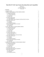
Figure 2: The Kaul-Tronics NPRM-10 mount for the prototype SRT. Concrete blocks or other counterweights should be<br />
placed in the six sections around the perimeter.<br />
Once the mount is complete, the rotor or other chosen dish mount can be attached to it.<br />
Depending on which dish you are using, some form of bracket will have to be manufactured to<br />
attach the dish to the elevation axis of the SPID. As a specific dish is not currently supported by<br />
the SRT, you should consult with a technician or engineer on the design of the bracket and other<br />
custom hardware necessary for your installation.<br />
Assembly of the Feed and LNA<br />
The feed consists of a low-profile helical antenna backed by an aluminum cavity. The<br />
helix is composed of copper tape wrapped around a polystyrene foam core, with a foil plate to<br />
match its impedance to that of the cable, which is peripherally fed. The cavity is a simple round<br />
cake pan.<br />
The low-noise amplifier (LNA) is located in a watertight box mounted on the back of the<br />
cavity, and causes minimal additional blockage of the aperture. The LNA itself consists of two<br />
ultra-low-noise amplifier modules, a band-pass filter, and a bias-tee to power the amplifiers.<br />
Assembly of the LNA<br />
Only two holes are required in the LNA case, and their positions are shown in the image<br />
below. For this portion of the assembly you will need following components from the Feed and<br />
LNA portion of the parts list, as well as solder and tools:<br />
5