Haystack Small Radio Telescope - MIT Haystack Observatory
Haystack Small Radio Telescope - MIT Haystack Observatory
Haystack Small Radio Telescope - MIT Haystack Observatory

Create successful ePaper yourself
Turn your PDF publications into a flip-book with our unique Google optimized e-Paper software.
<strong>Haystack</strong> <strong>Small</strong> <strong>Radio</strong> <strong>Telescope</strong><br />
Hardware Installation Manual<br />
Compiled by Dustin Johnson, June-August 2012
Table of Contents<br />
Assembly Note 2<br />
Acquiring Parts 2<br />
Dish Selection 2<br />
Mounting the Dish 3<br />
Assembly of the Feed and LNA 5<br />
Assembly of the LNA 5<br />
Assembly of the Feed 8<br />
Mounting the Feed 14<br />
Assembly of the Receiver 15<br />
Receiver Mounting Plate 16<br />
Receiver Box 16<br />
Assembly of the 90° Converter and High Pass Filter 16<br />
Final Assembly 22<br />
PC Interface 30<br />
Rotor Controller 30<br />
Rotor Alignment 31<br />
A Note on Calibration 32<br />
1
This manual contains all the necessary information to build and set up the required<br />
hardware for the SRT. There are five main components: the telescope (dish and mount), the feed<br />
and low-noise amplifier, the receiver, the antenna mount controller, and the PCI card. All of<br />
these components are necessary for a new SRT, but only the receiver and feed/LNA need to be<br />
built for an SRT upgraded from the original.<br />
Assembly Note<br />
When assembling the components of the SRT, keep in mind that the pictures provided are<br />
of the prototype built at <strong>Haystack</strong>, and some changes were incorporated into the plans based on<br />
lessons learned during assembly. As well, some parts were obtained from local stocks rather than<br />
the suppliers noted in the parts list, so appearance of some parts may be different.<br />
Acquiring Parts<br />
The components necessary for the SRT were selected to make assembly as easy as<br />
possible, with minimal machining, milling, and soldering. Components were also selected to<br />
come from as few different suppliers as possible: most come from Digi-Key, Mini-Circuits,<br />
Mouser, and McMaster-Carr. Most of the small hardware (i.e. screws, nuts, washers) are only<br />
available in bulk online, so it may be desirable to purchase these parts individually from a local<br />
hardware store.<br />
Dish Selection<br />
There are a variety of possibilities for the dish used for the SRT, depending on what it is<br />
used for and the budget available. The most versatile but most expensive choice is a motorized,<br />
computer-controlled mount with a 2.3m dish. The supported mount is the SPID RAS azimuthelevation<br />
rotor and controller from SPID Elektronik 1 of Poland, which the provided application<br />
is designed to interface with. The SPID costs $1,900 to $3,000, depending on the weight<br />
requirement.<br />
Due to the decline of C band satellite TV, large C band dishes are no longer as commonly<br />
available. A dish similar to that used on the prototype SRT is still available from Orbit<br />
Communications 2 . Sadoun 3 carries an inexpensive 1.8m dish, though its quality is not as high. A<br />
few other companies provide new dishes, such as Satcom Resources 4 and Global<br />
Communications 5 , though they are more expensive. Other dishes can often be found second-hand<br />
through the internet. For weight reasons, mesh dishes are the best, but are presently not<br />
manufactured in North America. RF Ham Design 6 of the Netherlands carries a variety of mesh<br />
dishes. The parts list includes the Orbit Communications, Sadoun and RF Ham Design dishes.<br />
If computer controlled steering is not desired or too expensive, several other options are<br />
available: a conventional polar satellite dish mouth, with or without motorized actuators for<br />
pointing; a hand or electrically controlled azimuth-elevation mount; or a fixed mount. Most new<br />
dishes are available with a polar mount and some with a non-motorized azimuth-elevation<br />
mount. Use of any mount but the SPID will require some modifications to the software.<br />
1<br />
www.spid.alpha.pl/english/11.php<br />
2<br />
www.orbitcommunications.com/cyberstore/product.asp?PID=S-7.5<br />
3<br />
www.sadoun.com<br />
4<br />
www.satcomresources.com<br />
5<br />
www.global-cm.net<br />
6<br />
www.rfhamdesign.com/index.html<br />
2
Mounting the Dish<br />
The dish can either be mounted on the roof of a building or somewhere outside. It is best<br />
to have as few obstructions to the sky as possible, though having a nearby tree act as an absorber<br />
for calibration may be useful. It is also desirable to have the telescope as far away from a<br />
building as possible to reduce interference from computers and other electronics.<br />
Two different mounting methods are recommended: a concrete pier or a non-penetrating<br />
roof mount. The concrete pier is permanent and requires a sufficient depth of soil to pour the<br />
mount. The non-penetrating mount can either be used on a flat roof or on flat ground, and can be<br />
disassembled and moved with relative ease.<br />
Concrete Pier<br />
This section is adapted from the original SRT manual.<br />
Remember that this is a permanent installation and moving the telescope requires a new<br />
pier to be built. Also note that soil mechanics can vary widely depending on the geographical<br />
location of the installation site. For this reason, it is recommended that you consult local building<br />
codes for information on how to properly install the pillar mount.<br />
� The pier foundation requires a round hole 30 inches in diameter and 4 feet deep. For<br />
areas that experience severe weather, be sure to dig the hole below the frost line.<br />
� Angle the sides of the hole outward so that it tapers towards the bottom. This will prevent<br />
the pillar from shifting during severe weather.<br />
� To improve drainage, fill the bottom of the hole with several inches of loose gravel.<br />
� The Spid rotor is designed to fit onto a 2.375” OD pipe. For the pier, use a section of 2”<br />
schedule 40 pipe 8 feet long (this has an outer diameter of 2.375”).<br />
� Place the pipe in the center of the hole and fill the hole with concrete (roughly 2/3 cubic<br />
yard), keeping the pipe level. This large a quantity of concrete should be prepared in a<br />
mixer or purchased from a concrete company.<br />
� Once the concrete is in, carefully level the pipe by placing a level against it, parallel to<br />
the pipe’s axis, and moving the pipe until the level reads vertical. Check this multiple<br />
times at two points 90° apart.<br />
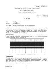
� Once the pipe is level, use several boards to keep it from shifting while the concrete<br />
cures.<br />
3
Figure 1: Leveling of the mounting pipe.<br />
Non-Penetrating Roof Mount<br />
These mounts are ideal for use on the flat roof of a building or on level ground, and can<br />
be relocated with little effort. However, mounts large enough for a 2.3m dish are not common<br />
commercially. The prototype SRT uses a Kaul-Tronics NPRM-10 mount. However, Kaul-<br />
Tronics appears to be defunct. As of this writing, this mount was still available from Skyvision 7 .<br />
Another roof mount is available from Orbit Communications 8 .<br />
The mount has a wide base supporting a 3” OD pipe. The SPID rotor is designed for a<br />
2.875” OD pipe. Alfa <strong>Radio</strong>, the SPID’s North American distributor, carries an adapter to fit on a<br />
4” pipe. The base is held down by ballast such as concrete blocks. If the mount is being placed<br />
on a roof, be sure to check with the appropriate authorities that the roof can support the load.<br />
7 www.skyvision.com/store/mi6012006.html<br />
8 www.orbitcommunications.com/cyberstore/cband/mounts.htm<br />
4
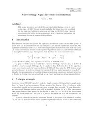
Figure 2: The Kaul-Tronics NPRM-10 mount for the prototype SRT. Concrete blocks or other counterweights should be<br />
placed in the six sections around the perimeter.<br />
Once the mount is complete, the rotor or other chosen dish mount can be attached to it.<br />
Depending on which dish you are using, some form of bracket will have to be manufactured to<br />
attach the dish to the elevation axis of the SPID. As a specific dish is not currently supported by<br />
the SRT, you should consult with a technician or engineer on the design of the bracket and other<br />
custom hardware necessary for your installation.<br />
Assembly of the Feed and LNA<br />
The feed consists of a low-profile helical antenna backed by an aluminum cavity. The<br />
helix is composed of copper tape wrapped around a polystyrene foam core, with a foil plate to<br />
match its impedance to that of the cable, which is peripherally fed. The cavity is a simple round<br />
cake pan.<br />
The low-noise amplifier (LNA) is located in a watertight box mounted on the back of the<br />
cavity, and causes minimal additional blockage of the aperture. The LNA itself consists of two<br />
ultra-low-noise amplifier modules, a band-pass filter, and a bias-tee to power the amplifiers.<br />
Assembly of the LNA<br />
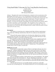
Only two holes are required in the LNA case, and their positions are shown in the image<br />
below. For this portion of the assembly you will need following components from the Feed and<br />
LNA portion of the parts list, as well as solder and tools:<br />
5
� 2 Mini-Circuits SF-SF50+ SMA-F to SMA-F adapters<br />
� 1 Mini-Circuits 086-4SM+ 4” SMA cable<br />
� 1 Mini-Circuits 086-6SM+ 6”SMA cable<br />
� 2 7/32” inner diameter O-rings<br />
� Hammond Manufacturing 1590WN1F waterproof aluminum enclosure<br />
� 2 Mini-Circuits ZX60-1614LN-S amplifiers<br />
� 1 Mini-Circuits VBF-1445+ bandpass filter<br />
� 1 Mini-Circuits ZFBT-4R2G-FT+ bias-tee<br />
� 22 gauge stranded wire, orange<br />
32.97mm<br />
23.19mm<br />
7.33mm<br />
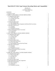
Figure 3: Position of the two holes in the LNA case. Note that vertical dimensions are from the top of the mounting plate<br />
and horizontal dimensions are from the edge at the same level as the hole. Both holes are ¼”.<br />
� Drill the two holes ¼” holes in the case. A drill press with a vice will probably work best.<br />
� Remove the nut and lock washer from one of the SMA-F to SMA-F bulkhead connectors.<br />
Slide an O-ring up the longer threaded portion until it is against the back of the flange.<br />
Insert the longer side through the lower hole in the case and secure it there with the lock<br />
washer and nut, tightening with a wrench.<br />
� Connect the filter to the out port of the ZX60-1614LN-S amplifier, and the SMA-M to<br />
SMA-M adapter to the “In” port. Attach the 3” SMA cable to the other end of the filter.<br />
6<br />
22.82mm
Place this assembly in the box and connect the SMA-M to SMA-M adapter to the end of<br />
the SMA bulkhead connector.<br />
� Attach the other end of the SMA cable to the “In” port of the second amplifier, and put it<br />
in the case as shown below.<br />
� Cut two pieces of +12V wire and tin their ends and the +12V pins of the amplifiers.<br />
Connect the two +12V pins with one wire, and attach the other to the +12V pin of the<br />
amplifier not connected to the bulkhead adapter, as shown below:<br />
Figure 4: The amplifiers and filter mounted in the LNA case. The black tube on the wires is 3.4mm heat-shrink tubing,<br />
and is not necessary.<br />
� Attach the 4” SMA cable to the “Out” port of the second amplifier and to the “RF” port<br />
of the bias-tee.<br />
� Prepare the other SMA-F to SMA-F bulkhead connector as before and insert it through<br />
the second hole.<br />
� Connect the “RF&DC” port of the bias-tee to the bulkhead connector.<br />
� Tin the +12V pin of the bias-tee and solder the remaining +12V wire to this pin.<br />
� Due to the presence of the bias-tee, the LNA has to be connected to the receiver for<br />
testing. The procedure for doing so is described after the receiver assembly instructions.<br />
7
� Remove the adhesive backing from the rubber gasket provided with the case and apply it<br />
to the lid. The completed assembly is shown below. The lid can now be screwed onto the<br />
case with the provided screws. It is advised that the connectors be labeled to prevent<br />
improper connection. Some form of weatherproof label should be used.<br />
Figure 5: Completed LNA case with gasket on the lid.<br />
Assembly of the Feed<br />
The helical antenna is the only component that has to be scratch built, and minimal<br />
machining is required for the other components. Drawing “Feed.pdf”, reproduced below, shows<br />
the feed and all dimensions. You will need the remainder of the components from the LNA and<br />
Feed section of the parts list, plus solder and tools.<br />
� Begin by cutting a piece of the foam rod to 73.7mm in length. Drill a 6.35mm (1/4”) hole<br />
all the way along the axis of the rod.<br />
� Select an arbitrary location on the lower edge of the rod and draw a mark 1mm from the<br />
lower edge. Make two more marks vertically above this mark, each 30mm above the<br />
mark below.<br />
8
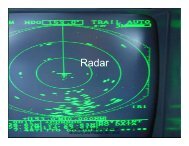
Figure 6: Mechanical drawing of the feed and LNA mounting plate<br />
9
� Cut out a strip of copper tape 4mm wide and 439mm long. Tape one end at the lowest<br />
mark on the rod and wrap the strip around the foam so that the lower edge of the strip is<br />
flush with the two marks made earlier. Tape the top end of the strip to the foam. It should<br />
be 15mm past the last mark.<br />
� With a ruler, go around the helix and make sure that the lower edge of the strip is always<br />
30mm above the lower edge of the turn below. Once the helix is adjusted, periodically<br />
mark its position on the foam with a marker.<br />
� Take the strip off the foam and measure in 15mm from the lower end of the strip, and<br />
bend the foil here. Make another mark 13mm from the first, and then another 26.25mm<br />
past that.<br />
� Remove the backing from the bent portion and fold the copper over on itself. Place the<br />
bend on the lowest mark on the foam and start to remove the backing and apply the foil to<br />
the foam, keeping the helix aligned with the marks made earlier.<br />
Figure 7: The helix attached to the foam cylinder. Note the area for attaching the wave trap, the bent portion away from<br />
the cylinder (note that in this image it is longer than required), and the blue alignment markings on the foam.<br />
� Cut out a piece of foil 26.25mm by 13mm, leaving an additional 3 to 4mm wide strip on<br />
one of the long edges, to form the impedance matching section.<br />
10<br />
Impedance<br />
matching section<br />
attachment area
� Fold this extra strip so that it is 90° to the rest of the foil. Center it on the helix between<br />
the two marks that are 26.25mm apart and solder the extra strip to the helix. This will<br />
cause some of the foam immediately under the soldered joint to melt. This is not a<br />
problem.<br />
� Apply a small amount of solder to the end of the bent-over portion of foil and to the pin<br />
of the SMA connector. Solder these two together so that the threaded portion of the SMA<br />
connector is pointed downwards. It may be helpful to cut off the ground pins on the<br />
connector closer to the foam rod.<br />
� Place a ¼” O-ring on the SMA connector and push it to the end of the threads.<br />
Impedance<br />
matching<br />
section<br />
Figure 8: The impedance matching section and SMA connecter attached to the helix.<br />
� Drill the holes in the cake pan indicated on the drawing of the feed. All are referenced to<br />
the center hole, so this can easily be performed on a milling machine with digital readout.<br />
Note that four of the holes are for mounting the feed to the dish, and these may have<br />
to be moved depending on the type of dish used.<br />
� Insert the 1/4-20x3.25” bolt through the rod so that the head of the bolt is at the top of the<br />
rod.<br />
� Cut out a 63mm square piece of the PC board and drill a ¼” hole in the center, and a ¼”<br />
indent and a Ø6-32 OD hole to the side as indicated in the drawing.<br />
11
� Run the ¼” bolt through the center hole of the board and the cake pan and a 6-32x1”<br />
machine screw though its holes in the PC board and pan. Make sure the SMA-F<br />
connector goes through its hole in the pan. Secure the ¼-20 bolt with a nut and washer<br />
and hand tighten. Carefully secure the SMA connector with a ¼” washer and its lock<br />
washer and nut. Make sure that the soldered end of the SMA connector is against the<br />
bottom of the cake pan and not propped up by the PC board.<br />
� The feed’s performance can now be tested with a network analyzer, if available. To do<br />
so, hook the network analyzer to the SMA connector and set it to measure S11. It should<br />
be around -20 dB.<br />
Figure 9: The helical antenna attached to the feed.<br />
� A shorted ¼ wavelength stub should be added to the feed to act as a DC path for<br />
lightning and static protection for the amplifiers.<br />
o Cut out a 42mm long piece of semi-rigid coaxial cable (shorter than ¼ wavelength<br />
due to the speed of propagation).<br />
o Strip the shield and insulation away from about 2mm of center conductor on one<br />
end and 4mm on the other end.<br />
o Bend over the 4mm end so that it touches the shield and solder it to the shield.<br />
12
o On the inside of the feed, solder the center connector of the stub to the center pin<br />
of the SMA connector, and the shield of the stub to one of the ground pins on the<br />
SMA connector, as shown below:<br />
Figure 10: Close up of the ¼ wavelength stub attached to the SMA connector.<br />
� The LNA mounting plate now has to be made. All dimensions are referenced to a single<br />
point, so this can easily be carried out on a milling machine with digital read-out. If the<br />
plate was obtained from Online Metals or a similar source, make sure that all dimensions<br />
are correct before drilling.<br />
� Once the plate is made, secure it to the back of the pan with two 6-32x1” machine screws<br />
and nuts through the holes in the corners, and 6-32x3/8” machine screws and nuts<br />
through the holes near the center, tightening them all with a wrench.<br />
� Put two more 6-32x1” machine screws through the holes on the far end of the plate and<br />
secure them with nuts.<br />
� Thread a nut onto each of the 1” machine screws and place a lock washer on top of it.<br />
� Place the LNA case onto the machine screws and connect the “To Feed” port of the LNA<br />
to the SMA connector on the feed with a SMA-M to SMA-M right angle connector.<br />
� Raise the nuts on the four machine screws until the LNA case is parallel to the back of<br />
the pan.<br />
� Thread another nut onto each of the four machine screws and tighten the nuts with a<br />
wrench, securing the LNA in place.<br />
13
Figure 11: The completed feed and LNA assembly.<br />
Mounting the Feed<br />
As noted earlier, the drawing of the feed shows four ¼” holes. These are based on the<br />
Kaul-Tronics 2.3m dish used for the prototype dish at <strong>Haystack</strong>. However, the dish you used<br />
may be different, and you will have to modify the size and placement of these holes accordingly.<br />
The feed should be mounted so that the focus of the dish is on the axis of the helix, half way<br />
along its length. To find the focus of your dish, stretch a string or wire across it to measure the<br />
diameter D. Then measure the distance d from the string to the center of the dish. The focal<br />
length f, measured from any point on the dish’s surface to the focus, can be found by:<br />
To connect the feed to the receiver, LMR-240 and LMR-400 coaxial cable was used. On<br />
the 2.3m prototype dish, a 10ft section of LMR-240 with SMA-M connectors on either end was<br />
run from the “To Receiver” connector on the LNA box along one of the quadrapod legs and<br />
round the back of the dish to the mount. It was secured to the dish every 6”-8” using UVresistant<br />
zipties. A loose section to allow full rotation of the dish hung off the mount. A 50’<br />
section of LMR-400 with SMA-F connectors on either end ran from the telescope inside to the<br />
14
eceiver location. To protect the connection between the LMR-400 and the LMR-240 at the<br />
telescope, a plastic drink bottle was cut off near the bottom and a hole large enough to allow<br />
through a SMA connecter was drilling in the cap. The LMR-240 was fed through this hole and<br />
sealed in place with electrical tape. The two cables were connected together inside the bottle:<br />
Figure 12: Weather-proof connection between the two coaxial cables.<br />
Assembly of the Receiver<br />
The receiver is a combination of an image rejection mixer and a two stage amplifier. It<br />
contains a non-tunable 1416 MHz local oscillator for receiving the 21cm band. The receiver and<br />
LNA in combination should provide approximately 71 dB of gain.<br />
The receiver was designed to make assembly as easy as possible. Most components are<br />
connected with SMA threaded cables and connectors, and minimal soldering is required. Some<br />
holes need to be drilled in the receiver case and the component mounting plate. The component<br />
mounting plate can easily be made on a milling machine with a digital read-out, and the<br />
mechanical drawing of the plate references all dimensions to a single point.<br />
The IF 90° combiner and high pass filter are not currently available as stand-alone<br />
modules, and thus they have to be assembled from surface mount components and an enclosure.<br />
Detailed instructions on this assembly are provided below. You will need the components from<br />
the Receiver section of the parts list, plus solder and tools.<br />
15
Receiver Mounting Plate<br />
The CAD drawing “ReceiverMountingPlate.pdf”, reproduced below, shows the locations<br />
and sizes of all of the holes necessary in the component mounting plate. There is a hole in each<br />
corner to mount the plate to the receiver box. All dimensions are referenced to the lower left<br />
corner of the plate. This allows the holes to be easily drilled on a milling machine with digital<br />
read-out. If such a machine is not available, a drill press, ruler, and careful measurements should<br />
suffice. If the plate was obtained from Online Metals or a similar source, make sure that all<br />
dimensions are correct before drilling.<br />
Receiver Box<br />
Seven holes need to be drilled in the receiver box: four for mounting the component<br />
plate, two for SMA connectors to the antenna and to the PCI board, and one for the power cord.<br />
A hand drill or drill press can be used. Ensure that the holes are accurately positioned. The<br />
flanges on the long edges of the box will have to have about a millimeter ground off of each one<br />
to allow the component mounting plate to easily slide in. Refer to drawing “ReceiverCase.pdf”,<br />
reproduced below, for dimensions.<br />
Assembly of the 90° Combiner and High Pass Filter<br />
This is the only component of the receiver that requires much work to build. You will<br />
need:<br />
� Mini-Circuits PSCQ-2-8+ power combiner<br />
� Pomona Electronics 2392 shield box with 3 BNC female tee<br />
� 3 Mini-Circuits SF-BM50+ SMA-F to BNC-M adapters<br />
� TDK 0.0033 µF ceramic capacitor<br />
� Vector Circboard 3677-6<br />
� Wire<br />
� Solder<br />
� The power combiner/high-pass filter module will be mounted on a piece of the Vector<br />
Circboard which is vertically installed in the box. Cut out a piece of the Circboard to fit<br />
vertically, lengthwise in the box. It will be approximately 19mm tall by 53mm long. Cut<br />
it from a part of a board so that one of the ground planes will run along the top of the<br />
board.<br />
� Place the power combiner on the Circboard and solder it in place as shown below. Ensure<br />
that none of the pins on the power combiner are connected to a plane on the Circboard.<br />
16
Figure 13: Mechanical drawing of hole locations on the receiver mounting plate<br />
17
Figure 14: Mechanical drawing of hole locations in the receiver case<br />
18
Figure 15: The power combiner attached to the Circboard.<br />
Figure 16: Placement of the power combiner on the board. From this perspective, pin 2 is in the upper left corner.<br />
19
� Next, the wires that attach the pins of the power combiner to the connectors are soldered<br />
onto the connectors. 22 gauge stranded wire was used, soldered onto each connector and<br />
then cut down to about 4cm in length.<br />
Figure 17: Wires attached to the connectors before being cut.<br />
� Strip about 7mm of insulation off of the end of each wire and tin it. As of this writing pin<br />
1 on the power combiner is the sum, pin 2 is +90° and pin 5 is 0°. All other pins are<br />
ground except 6, which is unused. The current data sheet for the power combiner should<br />
be consulted prior to assembly.<br />
� Push the stripped and tinned end of the wire through a hole in the circuit board adjacent<br />
to its pin. Loop the end of the wire around the pin and solder in place except for pin 1<br />
(sum), making sure that the wire does not contact another pin or the ground plane.<br />
� In the accompanying pictures, the blue wire attaches to the sum port (via the capacitor),<br />
red to +90°, and black to 0°.<br />
� A short piece of solid wire can be used to connect one of the ground pins on the power<br />
combiner to the ground plane of the board.<br />
� Loop one lead of the capacitor about pin 1 and the other lead about the end of the blue<br />
wire and solder in place. This completed assembly is shown below:<br />
20
Ground jumper<br />
Figure 18: Wires and ground jumper attached to the board.<br />
� The final step is to fix the board into the box. The board should slip in so that the ground<br />
plane at the top of the board is pressed against the ground pins of the connectors on either<br />
end of the box, and the bottom of the board is against the insulator around the pin for the<br />
central connector.<br />
� If the sum wire presses against one of the ground pins, remove the pin and cut off the end<br />
before putting it back in.<br />
� Solder the ground pins on either end to the ground plane on the top of the board. A small<br />
piece of bare wire can be placed on top of the ground pin if necessary to connect the pin<br />
to the plane:<br />
21<br />
Pin 2 (+90°)<br />
Pin 5 (0°) Pin 1 (Sum)<br />
Wire to Sum<br />
connector
Solder connections<br />
Figure 19: The board inserted in the box.<br />
� Screw the provided cover onto the box and attach the SMA to BNC adapters. It is<br />
recommended that the box be labeled to indicate which connector is which.<br />
� To test that the assembly was successful, attach a signal generator at 2-4 MHz to the sum<br />
port, and view the two outputs together on an oscilloscope. The two sine waves should be<br />
offset from each other by 90°. The signal should be cut off below about 1 MHz.<br />
Final Assembly<br />
Now that all components are ready, the receiver can be assembled. All wires used were<br />
22 gauge stranded wire. Note that in the pictures, brown wire is ground for all voltages, yellow is<br />
+15V, orange is +12V, and red is +5V. Heat-shrink tubing is placed over several connections,<br />
but this is not required and only helps to prevent shorts. The image below shows the completed<br />
plate with components labeled. A close-up view of the voltage regulator assembly is later<br />
provided. Also refer to the electrical schematic of the system, included below and in the file<br />
“ElectricalSchematic.pdf”.<br />
22
90° combiner/<br />
filter<br />
10MHz filter<br />
Mixer<br />
Local oscillator<br />
1 st IF amp.<br />
90° splitter<br />
Mixer<br />
RF splitter<br />
Figure 20: The completed component mounting plate in the receiver case.<br />
23<br />
7MHz filter<br />
2 nd IF amp.<br />
Power<br />
supply<br />
Voltage<br />
regulators<br />
Termination<br />
Bias-tee<br />
RF amp 1420-70 MHz filter
Figure 21: electrical schematic of the receiver, LNA, and computer interface.<br />
24
� Take four of the 4-40x1/2” standoffs and place them in the mounting holes in the corners<br />
of the plate, securing them with nuts.<br />
� Bolt the two voltage regulators to the component plate, with a solder lug between each<br />
regulator and the screw head, positioned so that the ends of the lugs are facing one<br />
another.<br />
� Solder the ends of the lugs together to ensure that they are well connected.<br />
� Attach the capacitors between the regulators and the solder lugs and solder in place, as<br />
shown in the picture below and the electrical schematic.<br />
� Solder a short piece of +15V wire between the two inputs of the voltage regulators,<br />
sliding a piece of 3.4mm and a piece of 1.5mm heat-shrink tubing onto it first. Slide the<br />
1.5mm tubing over the connection on the 5V regulator when finished.<br />
� Solder a longer piece of +15V wire (about 12cm) to the input pin of the 12V regulator,<br />
and slide the 3.4mm tubing over this connection. The following picture shows a close-up<br />
of the voltage regulators after assembly is complete. Note that the 1.5mm heat-shrink<br />
tubing used is clear, and the 3.4mm tubing is black.<br />
�<br />
Ground to power supply 15V from power supply<br />
Solder lugs<br />
5V to LO and RF amp<br />
Figure 22: Close-up of the voltage regulators. The 5V is on the left and the 12V on the right.<br />
25<br />
12V to bias-tee<br />
12V to IF amps
� Screw the VBF-1445+ bandpass filter directly to the “RF” port of the bias-tee.<br />
� Attach an SMA-M to SMA-M adapter to the other end of the filter, and attach the “In”<br />
port of the ZX60-33LN-S+ amplifier to the other end of the adapter. Lightly tighten all<br />
these connections with a wrench.<br />
� Bolt the bias-tee to the board, “RF&DC” port towards the near narrow edge of the plate,<br />
with two 5-40x1” screws, placing a washer between the nut and the top of the bias-tee.<br />
� Bolt the amplifier to the board with two 2-56x1/2” screws, placing two nuts between the<br />
plate and the amplifier on each screw, so that the amplifier is level.<br />
� Bolt the ZX10-2-252-S+ RF splitter to the board, the connector on the side facing the<br />
close long edge of the plate. Use two 2-56x1/4” machine screws and nuts.<br />
� Attach the “Sum” port of the ZX10Q-2-19 90° splitter to the RF output of the Luff<br />
Research oscillator with one of the SMA-M to SMA-M adapters, tightening the<br />
connections lightly with a wrench.<br />
� Bolt the Luff Research oscillator to the board with four 4-40x3/4” screws, running them<br />
through a washer and then a nut between the plate and the oscillator. This should allow<br />
the oscillator and 90° splitter to both be level.<br />
� Bolt the splitter to the plate with two 2-56x3/8” screws and nuts.<br />
� Attach the ANNE-50L+ termination to the 90° splitter on the end opposite the oscillator.<br />
Tighten it lightly with a wrench.<br />
� Attach the “IF” ports of the two mixers to the 90° and 0° ports of the combiner module<br />
built earlier, using the two SMA-M to SMA-M right-angle adapters and two SMA-F to<br />
BNC-M adapters, lightly tightening the connections with a wrench.<br />
� Attach the other four 4-40x1/2” standoffs to the mixers with nuts.<br />
� Bolt the standoffs to the plate with 4-40x1/4” screws.<br />
� Attach a third SMA-F to BNC-M adapter to the sum port of the combiner module.<br />
� Attach the SLP-10.7+ low pass filter to the “In” port of one of the ZFL-500-LN+<br />
amplifiers.<br />
� Attach one of the SMA-M to BNC-M adapters to one end of the BLP-7-75+ low pass<br />
filter, and the BNC-F to SMA-M adapter to the other end.<br />
� Connect the other end of the BLP-7-75+ low pass filter to the “In” port of the second IF<br />
amplifier. Note that the BLP-7-75+ filter may become available with SMA connectors in<br />
the future, and it is recommended that BNC version be replaced should this happen.<br />
� Bolt this entire assembly to the plate with four 5-40x1” screws, two through each<br />
amplifier, with a washer between the nut and the top of each amplifier.<br />
� Bolt the power supply to the board with two M3x6 screws, with the screw terminal near<br />
the closer short edge of the board.<br />
� Strip the insulation from the end of the long +15V wire soldered to the 12V voltage<br />
regulator and crimp it into a ring terminal. Attach this to the +V terminal of the power<br />
supply.<br />
� Solder a ground wire onto the ground lugs of the voltage regulators. Strip the insulation<br />
from the other end and crimp a ring terminal onto it. Attach this ring to the –V terminal<br />
of the power supply.<br />
� Strip off a short section of the outer insulation from the power cable and separate the<br />
three wires. Strip off about 7mm of insulation from each wire and twist the strands<br />
together. Crimp a ring terminal on each wire. Attach each wire to the terminal on the<br />
26
power supply. Be sure that the wires go to the correct terminals before powering the<br />
supply: black to L, white to N, and green to ground.<br />
� Before wiring in the amplifiers, bias-tee, and oscillator, check the connections on the<br />
voltage regulators and make sure that there are no shorts. Plug in the power supply and<br />
make sure that each regulator is supplying the correct voltage. Once this test is complete,<br />
the wires can be soldered on.<br />
� Solder a piece of ground wire between the ground pin of the bias tee and the ground pin<br />
of the 12V regulator, sliding a piece of 1.5mm heat-shrink tubing over this connection.<br />
� Connect the +12V pin of the bias-tee to the output pin of the 12V regulator.<br />
� Solder another +12V wire onto the output pin of the 12V regulator, making sure it is long<br />
enough to reach the second IF amplifier.<br />
� Strip the insulation from the ends of another piece of +12V wire, making sure that it is<br />
long enough to connect the +15V pins of the two IF amplifiers. Note that both IF<br />
amplifiers are being powered by 12V rather than 15V.<br />
� Twist together one end of the wire from the 12V regulator to the second IF amplifier and<br />
one end of the wire that will connect the IF amplifiers. Tin the connection and solder it<br />
onto the +15V pin of the second IF amplifier.<br />
� Cut a piece of +5V wire long enough to reach from the output pin of the 5V regulator to<br />
the 5V pin of the local oscillator and strip insulation off of each end.<br />
� Cut another piece of +5V wire long enough to connect the 5V pins of the local oscillator<br />
and ZX60-33LN-S+ amplifier and strip insulation off the ends.<br />
� Twist together and tin one end of each wire, and tin the other ends of the wires.<br />
� Solder the twisted connection to the 5V pin of the local oscillator, and the other ends to<br />
the output of the 5V regulator and the 5V pin of the amplifier.<br />
� Shorten the leads on the 1 µF capacitor, wrap them around the 15V and ground pins of<br />
the first IF amplifier, and solder in place.<br />
� Shorten the leads of the 1 mH inductor and tin them. Solder one lead to the 15V pin of<br />
the first IF amplifier. Connect the loose end of the +12V wire from the second IF<br />
amplifier to the other end of the inductor. This is shown below:<br />
27
1 µF capacitor<br />
Figure 23: Filtering on the power to the first IF amplifier.<br />
� Using a heat gun, carefully shrink the heat-shrink tubing on the voltage regulator<br />
connections. Take care to not let any of the surrounding components get too hot.<br />
� The SMA cables between the components can now be attached. Lightly tighten each<br />
connection with a wrench. The following table shows which lengths to use:<br />
Connection Cable length<br />
RF amplifier to RF splitter 4”<br />
RF splitter to RF ports of mixers 10”<br />
90° splitter to LO ports of mixers 6”<br />
90° combiner to filter 10”<br />
Table 1: SMA cable lengths for the receiver<br />
The receiver should now be tested to ensure it is working properly. Connect the LNA to<br />
the receiver with a short SMA cable. Connect the input of the LNA to a signal generator and set<br />
it to 1420 MHz with a power of around -80 dBm. Connect the output of the receiver to a<br />
spectrum analyzer, which should be set to display around 2 MHz to 6 MHz at a reference of 0<br />
dBm or thereabouts. Turn on the signal generator. There should be a clear signal at 4 MHz on the<br />
28<br />
1 mH inductor<br />
+12V wire
spectrum analyzer, at about 71 dB higher than the input from the signal generator. The frequency<br />
of the signal generator can be varied to check image rejection at an input of 1412 MHz.<br />
Once testing is complete, the receiver can be completed.<br />
� Detach the power cable from the power supply. Run the power cable through its hole in<br />
the receiver case and under the mounting plate, and reattach it to the power supply<br />
terminal.<br />
� Place the component mounting plate in the case and attach it to the case with four 4-<br />
40x3/8” screws, one into each standoff on the bottom of the plate.<br />
� Take the four adhesive rubber feet and apply them to the bottom of the case, near the<br />
corners, to prevent the screw heads from damaging whatever surface the receiver is<br />
placed on.<br />
� Remove the nut and lock washer from two SMA-F to SMA-F bulkhead adapters, and run<br />
the longer side into the case from the outside. They should line up with the “RF&DC”<br />
port of the bias-tee and the SMA-M to SMA-M adapter on the second IF amplifier.<br />
� Connect the bulkhead adapters to these ports, lightly tightening them with a wrench. The<br />
flange on the bulkhead adapters should be flush with the case.<br />
� Place the cover on top of the case and attach it with four ¼” #6 sheet metal screws.<br />
� It is recommended that the SMA connectors on the outside of the case be labeled, and a<br />
warning put on the connector to the bias-tee as it also carries 12 VDC:<br />
29
Figure 24: The finished receiver. Note that on the final design the power cord emerges from the back.<br />
PC Interface<br />
You will need the components from the PC Interface section of the parts list. Data from<br />
the receiver is collected by an A/D converter on a PCI card that occupies one of the card slots in<br />
a normal desktop computer. Install it following normal procedures for installing cards in PCs. To<br />
match the receiver to the ADC, connect the BNC tee to the first port of the card. Connect the<br />
SMA to BNC cable from the receiver onto one junction of the tee, and the 50Ω termination onto<br />
the other junction.<br />
Rotor Controller<br />
There are several possibilities for the controller that interfaces between the computer<br />
program and the rotor. The SPID rotor is available with two different control boxes/power<br />
supplies, both of which are made by SPID: the Rot2Prog and the MD-01/PS-01. They are<br />
30
available in many countries from different resellers (see the SPID website 9 for a list). Alfa<br />
<strong>Radio</strong> 10 is the North American distributor, though they only carry the Rot2Prog at present. The<br />
provided SRT software is (will be soon) compatible with both of the SPID controllers. The SRT<br />
software is designed to work with both azimuth and elevation limit switches. The SPID rotor<br />
comes equipped with only an elevation limit switch, and programmable electronic limits are built<br />
into the controller. The SRT software should work without the azimuth limit switch, but as of<br />
this writing this has not yet been tested.<br />
The schematics and code for the original Stamp microprocessor-based controller from<br />
CASSI are available on the <strong>Haystack</strong> website. The SRT control program was originally designed<br />
for this system and it is still supported but must be built by the user.<br />
Rotor Alignment<br />
To accurately track objects, the computer must know where the telescope is pointing. For<br />
the Rot2Prog and MD-01 controllers, the telescope’s position relative to north is electronically<br />
set. For the original CASSI system, azimuth limit switches must be installed and the rotor<br />
physically oriented towards north.<br />
For both controllers made by SPID, the telescope must be pointed due north and the<br />
controller reset.<br />
� First, open srt.cat in a text editor and change the azimuth limits line from:<br />
To:<br />
AZLI<strong>MIT</strong>S 28 355<br />
AZLI<strong>MIT</strong>S 0 355<br />
And the elevation limits line from:<br />
To:<br />
ELLI<strong>MIT</strong>S 7.0 89.0<br />
ELLI<strong>MIT</strong>S 0.0 89.0<br />
� Start the SRT software and command the telescope to zero azimuth and elevation using<br />
the azel button.<br />
� Once the telescope is pointed, carefully turn the mount until the dish is facing towards<br />
true north. The direction of true north can be found using a compass and knowing your<br />
location’s magnetic declination. This can be found for anywhere in the world from the<br />
calculator 11 on NOAA’s website.<br />
� If you are using the Rot2Prog controller: turn the controller off. Hold down the “F”<br />
button on the front of controller and while doing so, turn it back on. The controller should<br />
show 0.0 in both the azimuth and elevation readouts, and the mode readout should be<br />
blank.<br />
9 www.spid.alpha.pl/english/08.php<br />
10 www.alfaradio.ca<br />
11 www.ngdc.noaa.gov/geomag-web/#declination<br />
31
� If you are using the MD-01 controller: this controller is designed for use with a variety of<br />
different rotors, and several settings must be configured. Press “S” on the controller to<br />
enter configuration. The left and right arrow keys cycle though the settings. The up and<br />
down arrow keys cycle through the options for each setting. Pressing “S” with an option<br />
highlighted selects that option. The following settings need to be configured:<br />
o TEMPLATE: set to 1:AZ, 2:EL<br />
o CONTROL AE: set to COM 0. If this setting is not available, the TEMPLATE<br />
setting above was incorrectly set.<br />
o PROT.: set to SPID ROT<br />
o TYPE: set to DIGITAL<br />
o INPUT: set to ELECTRONIC<br />
o BAUD: set to 2400<br />
o DATA BITS: set to 8<br />
o STOP BITS: set to 1<br />
o PARITY: set to none<br />
� Press “F” and then the left arrow key on the controller to exit configuration mode and<br />
save the changes made. Press “F1” and the left arrow key to set current azimuth position<br />
to zero. Press “F1” and the up arrow key to set current elevation position to zero.<br />
For further information on these two controllers, see their manuals. They can be found on<br />
Alfa <strong>Radio</strong>’s website at:<br />
http://alfaradio.ca/downloads/Spid_CD_10may2012/<br />
The manuals are in their respective labeled folders.<br />
A Note on Calibration<br />
The SRT control software has a calibration feature which is made more accurate by<br />
having the telescope pointing at an absorber. There are three possibilities for such an absorber:<br />
hold one in front of the feed by hand; attach an absorber to an actuator which can move it in front<br />
of the feed; and have a position on the horizon where the telescope can point mostly/entire into a<br />
tree or bush.<br />
The absorber directly in front of the feed has the benefit of blocking out most RFI and HI<br />
emission from the calibration. It has the disadvantage of reflecting some noise from the LNA,<br />
which will not be an issue with the tree.<br />
The actuated absorber is not currently supported in the software or hardware, but it<br />
appeared in previous versions of the SRT and so documentation is available. Care must be taken<br />
to preserve the absorber foam from the elements and wildlife that may seek to use it for nest<br />
material.<br />
32