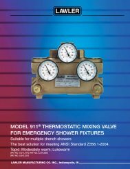
Series 911 E/F Emergency Eye Wash Valve
911E F Ins Sheet.indd - Lawler Thermostatic Mixing Valves
911E F Ins Sheet.indd - Lawler Thermostatic Mixing Valves
- No tags were found...

Create successful ePaper yourself
Turn your PDF publications into a flip-book with our unique Google optimized e-Paper software.
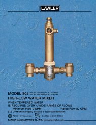
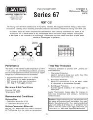
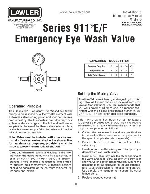
5330 East 25th StreetIndianapolis, Indiana 46218Phone (317) 261-1212Fax (317) 261-1208www.lawlervalve.com<strong>Series</strong> <strong>911</strong> ® E/FInstallation &Maintenance ManualM EFV DPAT. NO. 5,011,074.PAT. NO. 5,379,936.<strong>Emergency</strong> <strong>Eye</strong> <strong>Wash</strong> <strong>Valve</strong>6070 8090504030110120130CAPACITIES – MODEL <strong>911</strong>E/FPressure Drop PSI 5 10 20 30 45Tempered Flow 2 3 5 7 10Cold Water Bypass 1 2 4 5 7Operating PrincipleThis <strong>Series</strong> <strong>911</strong> <strong>Emergency</strong> <strong>Eye</strong> <strong>Wash</strong>/Face <strong>Wash</strong>mix ing valve is made of a thermostat element witha stain less steel sliding piston and liner housed in abronze cast ing. The ther mo stat ic car tridge re spondsto tem per a ture chang es in the hot and cold watersup plies. In the event the thermostatic el e ment failsor the hot water supply fails, the valve will pro videfull cold wa ter bypass fl ow.Note: <strong>Valve</strong> must be installed with check valves.If shut off valves are installed in the shower linefor maintenance purposes, provisions shall bemade to prevent unauthorized shut off.Caution: When maintaining and adjusting the mixingvalve, the delivered fl ushing fl uid tem per a tureshall be 60°F (15°C) to 95°F (35°C). In cir cum -stanc es where chemical re ac tion is acceleratedby fl ushing fl uid tem per a ture, a medical advisorshould be consulted for the optimum temperaturefor each application.Setting the Mixing <strong>Valve</strong>Caution: When maintaining and adjusting the mixingvalve, all fi xtures should be isolated from use.Lawler Manufacturing Co., Inc. recommends thatyou work safely at all times and in a manner consistent with the OSHA Lock/Tagout standard, 29CFR 1910.147 and other applicable standards.This mixing valve has been set at the factoryto deliver 85°F outlet fl ow. Should the valve re quireadjustment, or an ap pli ca tion re quire a dif fer ent settem per a ture, pro ceed as follows:1. Contact the proper medical and safety au thor i tiesto determine the correct water temperature forthe spe cifi c application (ie. chemicals).2. Remove the rounded cover nut on front of thevalve body.3. Create a draw on the mixing valve by open ing adown stream eye wash fi xture.4. Insert a 5 /32″ allen key into the stem opening ofthe valve and seat in the adjustment screw (notshown). Set the out let tem per a ture by turn ing thead just ment screw clockwise to re duce tem per a-ture, coun ter clock wise to in crease tem per a ture.Use the dial ther mom e ter to mea sure the outlettem per a ture.5. Replace rounded cover nut.(1)
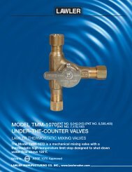
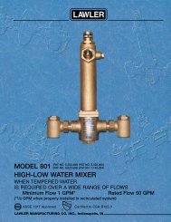
DIMENSIONS: 1/2″ inlets & outlets<strong>Valve</strong>Number A B C<strong>911</strong>E/F 9″ 4″ 8″5040603070 80Testing the Mixing <strong>Valve</strong>A90110120130The mixing valve and the emergency fixtures it servesshould be test ed week ly for prop er op er a tion.<strong>Valve</strong> temperature test procedure is as follows:1. Activate eye wash fi xture to observe and recordthe tem per a ture of the dial thermometer. If thetem per a ture of the thermometer is not cor rect,readjust the mixing valve according to the sec tion“Set ting the Mixing <strong>Valve</strong>”.2. Observe the fl ow from the emergency fi xtures toensure an adequate fl ow of water.In addition to testing for proper temperature, the coldwater by-pass and hot water shut down fea tures ofthe mixing valve should be tested week ly.The test procedure is as follows:1. Test valve temperature as described in Step 1and Step 2 above.2. Shut off the hot water supply to the mixing valve.Observe the outlet fl ow from the emergency fi x-tures to ensure an ad e quate fl ow of cold wa ter.A slight drop in fl ow may occur after shuttingdown the hot water supply to the mixing valve;how ev er, the drop should be minimal and for ashort duration.3. Open the hot water supply to the mixing valve.The thermometer should return to the set tempera ture.4. Shut off the cold water supply to the mixing valve.The fl ow of water should shut down rapidly.BC(2)5. Open the cold water supply. The thermometershould return to the set tem per a ture.Note: The thermometer should be checked at leastevery six months.Replacing the Thermostat ElementThe thermostat re place ment procedure is as fol lows:1. Shut off the hot water supply and cold watersupply to the mix ing valve.2. Remove the four cover screws (#9) and removethe front cover (#26) of the valve.3. Remove thermostat (#11) from the valve body.No special tools are necessary.4. Insert a dowel rod, pencil (eraser-end), or narrowpen into the open end of the thermostat. Push onthe dowel rod with your hand. If the thermostatfeels spongy or springy, the thermostat has lostits charge. If the thermostat feels solid or hard,the thermostat is good and operable.5. Be sure that the stainless steel piston (#15)moves freely up and down within the liner (#21).Lime or calcium buildup should be cleaned withvin e gar, green scotch pad, or fi ne emery cloth.CAPACITY OF TYPE <strong>911</strong>E/FTHERMOSTATIC MIXING VALVEFOR EMERGENCY SHOWERSPRESSURE DROP, POUNDS PER SQUARE INCH706050454035302520151/2″ MED10987651 2 3 4 5 6 7 8 9 10 15 20 30 35FLOW OF WATER, GALLONS PER MINUTENote: Gallon per minute ratings may vary dependingupon incoming water temperatures andpressures. Hot and cold water inlet pressuresmust be equal.Provisions shall be made to thermally isolatethe valve.
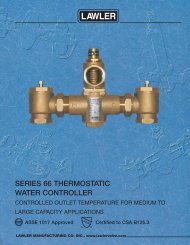
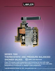
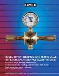
InstallationAfter installing the mixing valve, be sure to fl ush thesystem of debris. Lawler recommends isolation andcheck valves for proper maintenance.Typical Installation Figure 1When installed without a recirculation system:Install the valve as shown in Figure 1 with the mix ingvalve positioned below the hot water tank or heater.If this is not possible, pipe in heat trap as shown.Typical Installation Figure 2When installed with a recirculating pump on the hotwater supply line only:Note: If the valve is installed 20 feet or more fromthe wa ter heater, it is important to recirculate the hotwater supply to the mixing valve.Install the mixing valve as shown in Figure 2. Thenon-circulated loop should be limited to 10 feet andmust be fl ushed periodically.Caution: The cold water line must be installedso that it is not affected by excessively hot ambienttem per a tures. Provisions shall be madeto thermally isolate the valve. Cold water pipein stalled in the ceil ings of boil er rooms or roomsthat increase ambient temperature require a recirculatingpump.Figure 1Typical installation. <strong>Valve</strong> must beinstalled with check valves.WaterHeaterCWHeat Trap27″ DropHWStorageTankFigure 2Typical installation. <strong>Valve</strong> must beinstalled with check valves.<strong>Series</strong> <strong>911</strong>E/F1 valve pereye wash fixture<strong>Eye</strong>/Face<strong>Wash</strong>Note: The mixing valve must be installed withinlet check valves and the <strong>Eye</strong>wash/Facewashfi x ture should be installed 4 to 10 feet fromthe mix ing valve.CW<strong>Series</strong> <strong>911</strong>E/FNote: The valve body must be maintained at anambient room temperature of above 50°F to preventpremature closure of the safety back-seatmech a nism.Heat Trap27″ DropMaximum Inlet Pressure: 125 PSI.Recommended Supply Pressure: 65 PSI.Recommended Inlet Temperature: 120°F.**When supplying 140°F or greater, additional outletcontrols should be used.We guarantee the Lawler Mixing <strong>Valve</strong> to be freefrom defects in workmanship and material, and,for a period of one year from date of purchase,will replace any parts found by Lawler Man u fac -tur ing Co., Inc. to be defective. We will not be heldGUARANTEE(3)WaterHeaterStorageTankRecirculating Pumpresponsible, how ev er, for any labor in ci den tal to,or for any dam ag es caused by, de fec tive ma te ri al.Each mix ing valve is thor ough ly in spect ed and testedunder ac tu al con di tions at our factory.
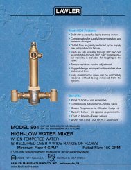
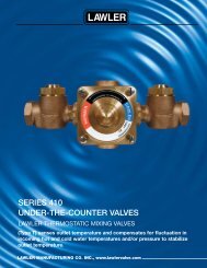
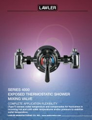
<strong>Series</strong> <strong>911</strong>E/F Test RecordLocation _______________________YEAR YEARYEARDateJanFebMarchAprilMayJuneJulyAugSeptOctNovDecJanFebMarchAprilMayJuneJulyAugSeptOctNovDecJanFebMarchAprilMayJuneJulyAugSeptOctNovDecT1(4)182114Parts Break DownRepair Kits and AssembliesItem Description Con tains Part No.A Repair Kit 11-12-15-18-21+B 79854-00B O-Ring & Gasket Kit 10-14-17-22-27 79961-00C Cover Assy. 4-5-10-26 78271-00D Piston & Liner Assembly 14-15-21-18-17 72904-60E Thermostat Assy. 10-11-27 78490-00151145926102712172522