Operator's Manual Model BBC Biopsy Breast Array Coil for ... - Invivo
Operator's Manual Model BBC Biopsy Breast Array Coil for ... - Invivo
Operator's Manual Model BBC Biopsy Breast Array Coil for ... - Invivo
- No tags were found...

Create successful ePaper yourself
Turn your PDF publications into a flip-book with our unique Google optimized e-Paper software.
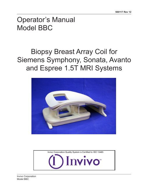
Operator’s <strong>Manual</strong><strong>Model</strong> <strong>BBC</strong>500117 Rev 12<strong>Biopsy</strong> <strong>Breast</strong> <strong>Array</strong> <strong>Coil</strong> <strong>for</strong>Siemens Symphony, Sonata, Avantoand Espree 1.5T MRI Systems<strong>Invivo</strong> Corporation<strong>Model</strong> <strong>BBC</strong>
500117 Rev 12First Edition March 2004Revision 12 April 2010©2004 <strong>Invivo</strong> CorporationAll rights reserved. No part of this publication may be reproduced, transmitted, transcribed, stored in aretrieval system, or translated into any language in any <strong>for</strong>m by any means without the written permission of<strong>Invivo</strong>.Licenses and TrademarksThe <strong>Invivo</strong> Logo is a registered trademark of <strong>Invivo</strong> Corporation.Symphony, Sonata, Avanto and Espree Systems are a registered trademark of the Siemens Medical Systems.This manual describes the use and operation <strong>for</strong> the <strong>Biopsy</strong> <strong>Breast</strong> <strong>Coil</strong> on Siemens Symphony, Sonata,Avanto and Espree 1.5T MRI Systems.Proper per<strong>for</strong>mance of this coil is guaranteed only while the coil is being used on the MR system (hardware/software level) specified at the time of purchase. Upgrades or other modifications to the system softwareand/or hardware may affect compatibility. Prior to upgrading your MR system, please contact your <strong>Invivo</strong>representative to discuss coil compatibility issues. Failure to do so may void your warranty.Attention, ConsultAccompanying DocumentsType BF EquipmentClass II Equipment0123NOTICE:THIS EQUIPMENT SHALL BE TRANSPORTED ANDSTORED UNDER THE FOLLOWING CONDITIONS:1. Ambient temperature range of -40°C to +70°C2. Relative humidity range of 10% to 100%, includingcondensation3. Atmospheric pressure range of 500 hPa to 1060 hPaWARNING: This Product contains chemicals, includinglead, known to the State of Cali<strong>for</strong>nia to cause birth defectsor other reproductive harm. Wash hands after handling.Caution:Federal law restricts this device to sale, distribution,and use by or on the order of a physician.There are no user serviceable parts inside. Opening the coil by personnel not explicitly authorized by <strong>Invivo</strong>Corporation will void the warranty. <strong>Invivo</strong> Corporation shall not be liable <strong>for</strong> any damage to, but not limited tothe operator, patient or the MRI scanner system, resulting from such unauthorized access.<strong>Invivo</strong> Corporation<strong>Model</strong> <strong>BBC</strong>
Introduction500117 Rev 12This manual describes the safety precautions, features, use and care of the<strong>Biopsy</strong> <strong>Breast</strong> <strong>Coil</strong>, <strong>for</strong> use with the Siemens Symphony, Sonata and Avanto1.5T MRI Systems. Please review this manual thoroughly be<strong>for</strong>e using thedevice.If you have any questions or comments on this manual, or need any assistancewith the use of the product, please contact your <strong>Invivo</strong> representative at:1-800-331-3220CompatibilityThe <strong>Invivo</strong> <strong>Model</strong> <strong>BBC</strong>, <strong>Biopsy</strong> <strong>Breast</strong> <strong>Coil</strong>, is compatible with the SiemensSymphony / Sonata [800162] and Avanto / Espree [800266] 1.5T MRI Systems.The minimum required system software levels are:Symphony/SonataVA21C with software patch 105278~ or ~syngo MR 2004A (N4 VA25A) (no patch required)AvantoVB11B (no patch required)EspreeVB12A<strong>Invivo</strong> Corporation<strong>Model</strong> <strong>BBC</strong>
500117 Rev 12<strong>Biopsy</strong> <strong>Breast</strong> <strong>Coil</strong>ComponentsThe <strong>Biopsy</strong> <strong>Breast</strong> <strong>Coil</strong> (800162 & 800266) consists of the following parts. Please inspect upon receipt tomake sure all parts have arrived and are in good order. Use this guide to refer to part names throughout thismanual.Lateral ImmobilizationSystem (2)<strong>Breast</strong> Phantom (1)Pillar Assembly (1)Immobilization Plates (*)Medial ImmobilizationSystem (2)cba<strong>Breast</strong> BlockerTray (1)Bottle PhantomHolder (2)Fluid Tray (2)Com<strong>for</strong>t Pad (1)Head SupportDevice (1)<strong>Biopsy</strong> <strong>Breast</strong><strong>Coil</strong> (1)* Plates “a” and “b” are included only in the <strong>Biopsy</strong> Practice KitFor use on EspreeSystem OnlyTable Positioner (2)These items are included in the <strong>Biopsy</strong> Practice KitProduct Qty Product Qty12 G Needle Block 1 <strong>Breast</strong> <strong>Biopsy</strong> Phantom 118 G Needle Block 1 Disposable Re-Order Form 112 G Needle Sleeve 1 Grid Immobilization Plate (b) 118 G Needle Sleeve 1 Pillar Immobilization Plate (a) 112 G Coaxial Needle 150/126 mm 1 Semi-Automatic <strong>Biopsy</strong> Kit 118 G Tumor Localizer Needle 100 mm 1 Sterilized VAB Hub Assembly 1ClipLoc 130 mm 1<strong>Invivo</strong> Corporation<strong>Model</strong> <strong>BBC</strong>
Table of Contents500117 Rev 12Introduction....................................................................................................... 3Compatibility..................................................................................................... 3<strong>Biopsy</strong> <strong>Breast</strong> <strong>Coil</strong> Components..................................................................... 4Chapter 1 - Safety............................................................................................. 7Training......................................................................................................... 7Quality Assurance......................................................................................... 7Indications..................................................................................................... 7Contraindications........................................................................................... 7Precautions................................................................................................... 7Cautions........................................................................................................ 7Emergency Procedures................................................................................. 8Technical Considerations.............................................................................. 9Chapter 2 - <strong>Coil</strong> Setup <strong>for</strong> Espree.................................................................. 10<strong>Coil</strong> Setup <strong>for</strong> Espree Use........................................................................... 10Chapter 3 - <strong>Coil</strong> Software Configuration....................................................... 11Configuration Procedure............................................................................. 11Chapter 4 - Quality Assurance....................................................................... 13Quality Assurance....................................................................................... 13<strong>Coil</strong> Selection.............................................................................................. 13Cleaning Procedures................................................................................... 14Chapter 5 - Using the <strong>BBC</strong> <strong>Coil</strong>..................................................................... 15Positioning the <strong>Biopsy</strong> <strong>Breast</strong> <strong>Coil</strong> on the Patient Table.............................. 15Establishing the Patient LANDMARK.......................................................... 16Connecting the Cable.................................................................................. 16Field of View and Coverage........................................................................ 17Selecting the Active <strong>Coil</strong>.............................................................................. 17Patient Com<strong>for</strong>t Pad.................................................................................... 18Chapter 6 - Scanning...................................................................................... 19Overview..................................................................................................... 19Auto Pre-Scan............................................................................................. 19Localizing with the Body <strong>Coil</strong>....................................................................... 19Scan Protocols............................................................................................ 19Head Support.............................................................................................. 20Positioning the Patient................................................................................. 20Continued on next page<strong>Invivo</strong> Corporation<strong>Model</strong> <strong>BBC</strong>
500117 Rev 12Table of ContentsContinuedChapter 7 - Grid Method: Lateral Access..................................................... 21Explanation.................................................................................................. 21Device Setup Step-by-Step......................................................................... 21Medial System Setup.................................................................................. 21Lateral System Setup.................................................................................. 23Localizing/ <strong>Biopsy</strong> Procedure Step-by-Step................................................ 24Chapter 8 - Grid Method: Medial Access..................................................... 27Explanation.................................................................................................. 27System Setup Step-by-Step........................................................................ 27Medial System Setup.................................................................................. 27Lateral System Setup.................................................................................. 28Localizing/ <strong>Biopsy</strong> Procedure Step-by-Step................................................ 29Chapter 9 - Pillar Method: Lateral Access................................................... 31Explanation.................................................................................................. 31Immobilization System Setup Step-by-Step................................................ 31Medial System Setup.................................................................................. 31Needle Hub Setup Step-by-Step................................................................. 32Lateral System Setup Step-by-Step............................................................ 33Pillar System Localization........................................................................... 34Chapter 10 - Pillar Method: Medial Access.................................................. 37Explanation.................................................................................................. 37Immobilization System Setup Step-by-Step................................................ 37Medial System Setup.................................................................................. 37Lateral System Setup.................................................................................. 38Pillar System Localization........................................................................... 38Chapter 11 - Installation and Maintenance................................................... 40Cleaning and Storage.................................................................................. 40<strong>Invivo</strong> Corporation<strong>Model</strong> <strong>BBC</strong>
Chapter 1 - Safety500117 Rev 12TrainingQualityAssuranceIndicationsContraindicationsThis manual contains detailed in<strong>for</strong>mation on the set-up, positioning and useof your <strong>Invivo</strong> Corporation coil. The instructions should be read carefully andthoroughly be<strong>for</strong>e attempting to scan patients with the coil.The procedure described in the Quality Assurance Section of this manualshould be per<strong>for</strong>med upon receipt of the coil to establish a baseline of coilper<strong>for</strong>mance. The procedure should be repeated at regular intervals.The coil is indicated <strong>for</strong> use, on the order of a physician, in conjunction with anMR scanner as an accessory to produce images of the breast.The operator should be aware of the following contraindications <strong>for</strong> use relatedto the strong magnetic field of the MR system:Scanning is contraindicated <strong>for</strong> patients who have electrically, magneticallyor mechanically activated implants (<strong>for</strong> example, cardiac pacemakers).The magnetic and electromagnetic fields produced by the MR System andcoil may interfere with the operations of these devices.Scanning patients with intracranial aneurysm clips is contraindicated.PrecautionsPrecautions should be taken when scanning patients with the followingconditions:Greater than normal potential <strong>for</strong> cardiac arrestIncreased likelihood of seizures or claustrophobiaUnconscious, heavily sedated, or confused mental stateInability to maintain reliable communicationsCautionsThe following general warning statements apply to scanning with a magneticresonance system. For further details, review the warnings in your MR systemOperator’s <strong>Manual</strong>.Do not cross or loop cables. Arcing and patient burns could result. Routecables out of the magnet so that they do not touch the patient.<strong>Invivo</strong> Corporation<strong>Model</strong> <strong>BBC</strong>
500117 Rev 12Ensure that the patient does not <strong>for</strong>m a loopwith any body parts. For breast coils inparticular, patients are imaged lying pronewith both arms extended above the head(superman). Do not allow patients to touchany part of the right hand or arm to anypart of the left hand or arm. The loop<strong>for</strong>med by doing so could cause an RFburn at the point of contact. Use pads toensure the patient’s hands do not touchany metal features of the patient tableor cradle. Be sure to educate the patientaccordingly and check the patient’s positionimmediately be<strong>for</strong>e the scan.Ensure that the patient is not touching the bore. If necessary, place padsbetween the patient and the surface of the bore.If the patient complains of warming, tingling, stinging, or similarsensations, promptly stop the scan procedure, examine the patient, andcontact the responsible physician be<strong>for</strong>e continuing the procedure. Payspecial attention to very young, sedated, or other compromised patientswho may not be able to communicate effectively.Patients with ferromagnetic metal implants should not be scannedbecause the magnetic field may interact with implanted surgical clips orother ferromagnetic materials.Persons with cardiac pacemakers or other implanted electronic devicesshould not enter the magnetic field zone delineated by the MR systemmanufacturer.There is a risk to scanning feverish or decompensated cardiac patients.Facial makeup such as eyeliner & mascara should be removed be<strong>for</strong>escanning because it may contain ferromagnetic material which cancause skin and eye irritation. Permanent eyeliner tattoos may cause eyeirritation due to ferromagnetic particles.Patients who work in environments in which there is a risk of havingembedded metallic fragments in or near the eye should be carefullyscreened be<strong>for</strong>e undergoing an MR exam.Visually inspect the cable insulator jackets, strain reliefs and connectorboxes be<strong>for</strong>e each use. If the insulation is broken, or if the cable is frayed,immediately discontinue use of the device.EmergencyProceduresIn the unlikely event that a coil creates smoke, sparks or makes an unusuallyloud noise, or if the patient requires emergency assistance:• Stop the scan if one is in progress.• Remove the patient from the scan room if medical treatment is needed.<strong>Invivo</strong> Corporation<strong>Model</strong> <strong>BBC</strong>
500117 Rev 12TechnicalConsiderationsThe coil and accessories require special conditions regardingelectromagnetic compatibility. The coil must be installed and used in ashielded scan room provided with the MR magnet and system. The usermust ensure that the scan room door is closed during system use. Failureto do so may cause reciprocal interference with portable and mobile RFcommunications equipment, affecting the per<strong>for</strong>mance of the MR coil and/or such equipment.The coil should only be used with the accessories specified in theOperator’s <strong>Manual</strong>.The use of accessories other than those specified in the Operator’s<strong>Manual</strong> may result in decreased ESD (electrostatic discharge) immunity ofthe coil or MR system, causing damage to the coil and/or system.The equipment should not be used with other coils or equipment present inthe MR scanner except as specified in the Operator’s <strong>Manual</strong>.Tampering with the cable pins and connector may damage connector andaffect coil or system per<strong>for</strong>mance. Please verify that connector and pinsare not damaged be<strong>for</strong>e use.<strong>Invivo</strong> Corporation<strong>Model</strong> <strong>BBC</strong>
500117 Rev 12Chapter 2 - <strong>Coil</strong> Setup <strong>for</strong>Espree<strong>Coil</strong> Setup <strong>for</strong>Espree UseIf you are using the breast coil on the Espree system you must first attach thetwo (2) table positioners to the coil prior to use. See the illustration below <strong>for</strong>reference.Note: The breast coil is designed to sit on top of the spine array on theEspree system and should only be used with the system spinearray installed on the patient table. The positioners are NOTdesigned to support the weight of the coil and patient. They aredesigned to keep the coil centered on the patient table.10 <strong>Invivo</strong> Corporation<strong>Model</strong> <strong>BBC</strong>
Chapter 3 - <strong>Coil</strong> SoftwareConfiguration500117 Rev 12ConfigurationProcedureThe <strong>Coil</strong> Software Configuration procedure is available on systems running thefollowing software versions:Symphony/Sonata VA25A or GreaterAvantoVB11A or GreaterEspreeVB12A or GreaterDo not attempt to per<strong>for</strong>mcoil software configurationwith system softwareversions lower than these• Select Options from the main menu tab• Select Local Service from the drop down menu• The following screen appears• Select Configuration<strong>Invivo</strong> Corporation<strong>Model</strong> <strong>BBC</strong>11
500117 Rev 12• The following screen appears• Select Next• From the resultingscreen selectAvail. <strong>Coil</strong>s• Add the <strong>Biopsy</strong> <strong>Breast</strong> <strong>Array</strong> <strong>Coil</strong> by checking the box next to 7Ch_<strong>Breast</strong>• Select Save• Select Finish• REBOOT SYSTEM NOW to save new coil in<strong>for</strong>mation12 <strong>Invivo</strong> Corporation<strong>Model</strong> <strong>BBC</strong>
500117 Rev 12Chapter 4 - Quality AssuranceQualityAssuranceBe sure that you have chosen the correct coil, and activate the desired coil(s)from the menu selection on the coil selection screen.<strong>Coil</strong> Selection<strong>Coil</strong> Selection: Bilateral <strong>Breast</strong>; Channels 1-7<strong>Coil</strong> Selection: Left <strong>Breast</strong>; Channels 4-7 <strong>Coil</strong> Selection: Right <strong>Breast</strong>; Channels 1-4<strong>Invivo</strong> Corporation<strong>Model</strong> <strong>BBC</strong>13
500117 Rev 12CleaningProceduresPatient contact parts <strong>for</strong> interventional use are sterile, single use disposableitems. The following parts, however, should be cleaned prior to and after eachuse.Protective gloves and eyewear are required when per<strong>for</strong>ming theprocedures set <strong>for</strong>th in these instructions, as well as compliance withyour institution’s biohazard/blood-borne pathogen safety protocols.Cleaning (RF <strong>Coil</strong>)The following parts require cleaning prior to and after each use:RF <strong>Coil</strong> HousingPatient Com<strong>for</strong>t PadProcedure:1. Inspect the above referenced parts <strong>for</strong> signs of surface contaminants.2. Dampen a soft cloth with a solution of 30% isopropyl alcohol (IPA) and70% water.3. Wipe all surfaces of the parts until all visible signs of surfacecontaminants are removed and allow to air dry. DO NOT pour thesolution directly on the RF coil housing.4. For any heavily soiled areas, use a soft cloth with additional solutionand rub the affected areas until all visible signs of surface contaminantsare removed.5. Dispose of any used cleaning materials in accordance with yourfacility’s biohazard material/blood-borne pathogen disposal protocols.Cleaning Procedure (<strong>Biopsy</strong> Device – Immobilization System)The following parts require cleaning prior to each use:Lateral Immobilization SystemMedial Immobilization SystemPillar AssemblySolid Immobilization PlatesPillar Fiducial MarkerProcedure:1. Follow the above procedures <strong>for</strong> cleaning of the RF <strong>Coil</strong>.2. Dampen a soft cloth with a solution of 30% isopropyl alcohol (IPA) and70% water. Wipe all surfaces of the Pillar Fiducial Marker and allow toair dry.3. Thoroughly clean all cracks/crevices in the rail/handle assemblies usingthe 30/70 IPA/water solution and a cotton swab and/or small bristlebrush (e.g. toothbrush).4. If there are any visible signs of contaminants on the rail/handleassembly screw heads, disassemble these parts, clean as describedabove and reassemble. DO NOT use ferromagnetic tools within theMRI environment. Per<strong>for</strong>m this step outside of the MR suite.5. Allow parts to air dry.6. Dispose of any used cleaning materials in accordance with yourfacility’s biohazard material/blood-borne pathogen protocols.14 <strong>Invivo</strong> Corporation<strong>Model</strong> <strong>BBC</strong>
Chapter 5 - Using the <strong>BBC</strong><strong>Coil</strong>500117 Rev 12Positioning the<strong>Biopsy</strong> <strong>Breast</strong><strong>Coil</strong> on thePatient TableThe <strong>Biopsy</strong> <strong>Breast</strong> <strong>Coil</strong> is designed <strong>for</strong> unilateral or bilateral breast imaging.Symphony, Sonata and AvantoYour Siemens spine array coil should be removed from the table top on theSymphony, Sonata and Avanto systems. The <strong>BBC</strong> is designed to rest directlyon the patient table. It is important that the coil lies directly on the patient table,and not on secondary cradle pads since this will elevate the patient’s breast toiso-center of the coronal scan plane.If some <strong>for</strong>eign object (sheet, strap, etc.) is beneath the coil housing, the coilmay move during the image acquisition, resulting in motion artifact. The coilmust be placed on the patient table with the cable exiting toward the magnet.Currently the Symphony, Sonata and Avanto systems only support headfirstimaging.EspreeThe spine array must be left on the table when scanning on the Espree system.If some <strong>for</strong>eign object (sheet, strap, etc.) is beneath the coil housing, the coilmay move during the image acquisition, resulting in motion artifact. The coilmay be placed with the cable towards OR away from the magnet.The Espree system supports both head-first and feet-first imaging.<strong>Invivo</strong> Corporation<strong>Model</strong> <strong>BBC</strong>15
500117 Rev 12Warning! Do not allow patients to touch anypart of the right hand or arm to any part ofthe left hand or arm. The loop <strong>for</strong>med bydoing so could cause an RF burn at the pointof contact. Use pads to ensure the patient’shands do not touch any metal features of thepatient table or cradle.Be sure to educate the patient accordingly andcheck the patient’s position immediately be<strong>for</strong>ethe scan.Establishingthe PatientLANDMARKConnecting theCableUse the open lateral side of the coil to visually center the breast in the coil. Askthe patient to move slightly superior or inferior until the breast is centered in theaperture.The patient must be positioned head-first face-down.The cable is connected to your system using a standard coil connector.Connect the coil as illustrated below:For Symphony/SonataFor Avanto/Espree16 <strong>Invivo</strong> Corporation<strong>Model</strong> <strong>BBC</strong>
500117 Rev 12Field of Viewand CoverageSelecting theActive <strong>Coil</strong>For unilateral imaging an FOV of 16 cm is suggested, depending upon breastsize. The <strong>Biopsy</strong> <strong>Breast</strong> <strong>Coil</strong> aperture is roughly 160 millimeters (16 cm) by160 millimeters (16 cm) in diameter. If both coils are active, a field of view of 32cm to 36 cm is suggested. You may use a smaller FOV if desired.The breast imaging plat<strong>for</strong>m contains both a left breast coil and a right breastcoil. Either one or both coils can be active at any given time. For the <strong>Biopsy</strong><strong>Breast</strong> <strong>Coil</strong>, there are three (3) tabs available to the user to select Bilateral(Both) or Unilateral (Left or Right only) modes of operation.For Bilateral Mode:For Unilateral Left <strong>Breast</strong>:For Unilateral Right <strong>Breast</strong> :Select BL3, BM and BR3Select BL3 and BMSelect BM and BR3<strong>Invivo</strong> Corporation<strong>Model</strong> <strong>BBC</strong>17
500117 Rev 12PatientCom<strong>for</strong>t PadFor patient com<strong>for</strong>t, a pad has been provided. The pad attaches to the <strong>Biopsy</strong><strong>Breast</strong> <strong>Coil</strong>. The lower end of the pad fits flush with Siemens Symphony tablepads.Center the pad openings over the apertures of the breast plat<strong>for</strong>m and secure.If the pad becomes soiled, it can be cleaned with a solution of 30% isopropylalcohol and 70% tap water.18 <strong>Invivo</strong> Corporation<strong>Model</strong> <strong>BBC</strong>
Chapter 6 - Scanning500117 Rev 12OverviewThe <strong>Biopsy</strong> <strong>Breast</strong> <strong>Coil</strong> is designed <strong>for</strong> proton imaging and is intended <strong>for</strong>imaging applications of the breasts. The fully integrated immobilization systemallows <strong>for</strong> two separate methods of immobilization, localization, and biopsyprocedures: the grid method, and the pillar method. We recommend that youbecome familiar with both methods in order to determine the method that ismost suitable <strong>for</strong> your imaging needs. The best way to acclimatize yourselfwith the <strong>Biopsy</strong> <strong>Breast</strong> <strong>Coil</strong> is to practice with a phantom.Two (2) different methods of lesion localization are offered; each has its ownadvantages. The pillar method allows the user to obtain X, Y, Z coordinatesand precise movement of the pillar based on these coordinates. The gridmethod also allows the user to obtain X, Y, Z coordinates; however, this methodof localization/biopsy is more visually oriented. We strongly suggest that youpractice BOTH methods on a phantom to learn each method.Auto Pre-ScanLocalizing withthe Body <strong>Coil</strong>Generally, the Symphony, Sonata, Avanto and Espree Systems’ auto pre-scanwill function normally when used with the open breast array coil.The <strong>Biopsy</strong> <strong>Breast</strong> <strong>Coil</strong> is designed to allow the Siemens body coil to be usedat any time while the coil is in the scanner. This allows a large FOV (40 cm)use of a body coil localizer, which is helpful in determining the left or right offsetrequired <strong>for</strong> imaging the breast.Scan Protocols<strong>Invivo</strong> recommends that you select imaging protocols that have beenestablished by your radiologists. Additional protocols can be found within yourSiemens Application Guides.<strong>Invivo</strong> Corporation<strong>Model</strong> <strong>BBC</strong>19
500117 Rev 12Head SupportPlace the Head Support Device at the head end of the <strong>Biopsy</strong> <strong>Breast</strong> <strong>Coil</strong>with the handle end of the Device away from the coil. Adjust the height of theHead Support <strong>for</strong> optimum patient com<strong>for</strong>t by pushing in the release button.Once desired position is reached, let release button out to lock Head Supportin place. Disposable face drapes are provided <strong>for</strong> use with the Head SupportDevice (as shown below). Face drapes have adhesive <strong>for</strong> secure positioning.Be sure to dispose of face drape after each use.Positioning thePatientPosition the patient prone, feet-first, centering the breasts in the apertures ofthe coil. Use the open lateral side of the coil to visually center the breasts inthe coil. The patient may rest their face on the Head Support, and the mirrorwill redirect their vision to see outside of the bore (towards the rear end of themagnet).Ensure that the patient does not <strong>for</strong>m a loopwith any body parts. For breast coils inparticular, patients are imaged lying pronewith both arms extended above the head(superman). Do not allow patients to touchany part of the right hand or arm to anypart of the left hand or arm. The loop<strong>for</strong>med by doing so could cause an RFburn at the point of contact. Use pads toensure the patient’s hands do not touchany metal features of the patient tableor cradle. Be sure to educate the patientaccordingly and check the patient’s positionimmediately be<strong>for</strong>e the scan.20 <strong>Invivo</strong> Corporation<strong>Model</strong> <strong>BBC</strong>
Chapter 7 - Grid Method:Lateral Access500117 Rev 12ExplanationDevice SetupStep-by-Step<strong>Invivo</strong> recommends that you become familiar with the set up and function ofthis device prior to use with a patient. We recommend that you practice ona phantom. The <strong>Biopsy</strong> <strong>Breast</strong> <strong>Coil</strong> provides means <strong>for</strong> unilateral or bilateralbreast immobilization. Immobilization is used when localization or biopsyprocedures are intended.With the <strong>Biopsy</strong> <strong>Breast</strong> <strong>Coil</strong> in position on the table, <strong>for</strong> unilateral procedures,place the Fluid Tray in the in the affected side lower aperture.Note: If a bilateral procedure is to be done, place a Fluid Tray in both lowerapertures.Medial SystemSetupEnsure both lock latches are in the unlocked - raised position on the MedialImmobilization System. If not, lift both lock latches. Making note of the pointedrail surface on both sides of the Grid Immobilization Plate, slide the Plate intothe Medial Immobilization System, leading with pointed end of rail guide, asshown below in left image. Depress both grid lock latches to lock the GridImmobilization Plate in place. See examples below.<strong>Invivo</strong> Corporation<strong>Model</strong> <strong>BBC</strong>21
500117 Rev 12Medial SystemSetupContinuedSlide the Medial Immobilization System into the rails of the affected side breastcoil aperture using the outer set of rails.IMPORTANT: You must depress the release button to adjust MedialImmobilization System.22 <strong>Invivo</strong> Corporation<strong>Model</strong> <strong>BBC</strong>
500117 Rev 12Lateral SystemSetupEnsure both grid lock latches are in the unlocked - raised position. If not, liftboth lock latches. Making note of the pointed rail surface on both sides ofthe Grid Immobilization Plate, slide the Plate into the Lateral ImmobilizationSystem. Depress both lock latches to lock the Grid Immobilization Plate inplace.Slide the Lateral Immobilization System into the rails of the affected side breastcoil aperture using the inner set of rails.<strong>Invivo</strong> Corporation<strong>Model</strong> <strong>BBC</strong>23
500117 Rev 12Localizing/<strong>Biopsy</strong>ProcedureStep-by-StepPlace a Vitamin E capsule, small almond piece or other commercially availableMR marker into one of the grid slots at either the head end or foot end. Thismarker will serve as an orientation reference. Make a note of what end youplaced this marker.Vitamin E capsuleTurn on MRI system alignment light and position the light on the approximatecenter of the breast phantom. Landmark and advance to scan. Acquire anaxial localizer and determine a target within the phantom that you wish tolocalize.Prescribe enough sagittal slices to image from the lesion target and includeenough slices to image laterally to visualize the impression of the grid.24 <strong>Invivo</strong> Corporation<strong>Model</strong> <strong>BBC</strong>
500117 Rev 12Localizing/<strong>Biopsy</strong>ProcedureStep-by-StepContinuedPlace a cursor over the center of the target lesion, keeping the cursor visible, ordepositing the cursor on all images - same location, scroll through the imagesmoving in the lateral direction. Continue until you see the image showingan impression of the grid plate on the surface of the phantom, and your MRmarker.With your MR marker serving as a reference point, determine the grid slot thatcorrelates with the position of the phantom lesion. That is, while viewing theimage displaying the grid impression and MR marker, count the number of gridslots to determine the slot that is over the cursor (lesion).Place the needle block in this slot. Place the Needle Block Holder in a grid slotadjacent to the Needle Block, and lock the Needle Block Holder in place bydepressing the tab on the Needle Block Holder. This will prevent the NeedleBlock from coming loose when a needle that was positioned through a hole iswithdrawn from the Needle Block.<strong>Invivo</strong> Corporation<strong>Model</strong> <strong>BBC</strong>25
500117 Rev 12Localizing/<strong>Biopsy</strong>ProcedureStep-by-StepContinuedDetermining Needle Placement:By dividing the needle block into 4 quadrants, choose the appropriate quadrantand estimate the appropriate needle hole within that quadrant.Needle depth is calculated as the distance from the first medial impression ofthe grid to the center of the lesion.IMPORTANT: Remember, the grid block is 2 cm thick and there<strong>for</strong>e 2 cm mustbe added to the lesion depth to determine total needle insertiondepth.Insert the needle to the depth of the phantom lesion, and rescan at this locationto verify proper needle placement. Once verified, obtain phantom lesionsample. Phantom is designed with simulated lesions that are MR visible. Thedye will help in verification.CAUTION:Be<strong>for</strong>e the intervention is per<strong>for</strong>med, a confirmationscan should be acquired with the sleeve (andpossibly stylette) inserted to ensure that the needleis positioned as desired. Incorporate the effects ofneedle throw into the risk evaluation.26 <strong>Invivo</strong> Corporation<strong>Model</strong> <strong>BBC</strong>
Chapter 8 - Grid Method:Medial Access500117 Rev 12ExplanationSystem SetupStep-by-Step<strong>Invivo</strong> Corporation recommends that you become familiar with the set up andfunction of this device prior to use with a patient. We recommend that youpractice on a phantom. The <strong>Biopsy</strong> <strong>Breast</strong> <strong>Coil</strong> provides means <strong>for</strong> unilateralor bilateral breast immobilization. Immobilization is used when localization orbiopsy procedures are intended.With the <strong>Biopsy</strong> <strong>Breast</strong> <strong>Coil</strong> in position on the table, <strong>for</strong> unilateral procedures,place the Fluid Tray in the affected side lower aperture. Place the <strong>Breast</strong>Blocker in the unaffected side upper aperture, with the single tab to the outside,or lateral aspect, as shown below.Medial SystemSetupEnsure both lock latches are in the unlocked - raised position on the MedialImmobilization system. If not, lift both lock latches. Making note of the pointedrail surface on both sides of the Grid Immobilization Plate, slide the Plateinto the Medial Immobilization System, leading with pointed end of rail guide.Depress both lock latches to secure the Plate in place.<strong>Invivo</strong> Corporation<strong>Model</strong> <strong>BBC</strong>27
500117 Rev 12Lateral SystemSetupWith Lateral Immobilization System, ensure both lock latches are in theunlocked - raised position. If not, lift both lock latches. Making note of thepointed rail surface on both sides of the Solid Immobilization Plate, slide thePlate into the Lateral Immobilization System, leading with pointed end of railguide. Convex side of plate must face toward the phantom. Depress both locklatches to secure the Plate in place.Slide the Lateral Immobilization System into the <strong>Biopsy</strong> <strong>Breast</strong> <strong>Coil</strong>.28 <strong>Invivo</strong> Corporation<strong>Model</strong> <strong>BBC</strong>
500117 Rev 12Localizing/<strong>Biopsy</strong>ProcedureStep-by-StepWorking from the unaffected side, reach under to the affected side MedialImmobilization System. Place a Vitamin E capsule, small almond piece orother commercially available MR marker into one of the grid slots at either thehead end or foot end. This marker will serve as an orientation reference. Makea note of what end you placed this marker.Vitamin E capsuleTurn on MRI system alignment lights and position the light on the approximatecenter of the breast phantom. Landmark and advance to scan. Acquire anaxial localizer and determine a target within the phantom that you wish tolocalize.Prescribe enough sagittal slices to image from the lesion target and includeenough slices to image laterally to visualize the impression of the grid.Place a cursor over the center of the target lesion, keeping the cursor visible, ordepositing the cursor on all images - same location, scroll through the imagesmoving in the lateral direction. Continue until you see the image showingan impression of the grid plate on the surface of the phantom, and your MRmarker.With your MR marker serving as a reference point, determine the grid slot thatcorrelates with the position of the phantom lesion. That is, while viewing theimage displaying the grid impression and MR marker, count the number of gridslots to determine the slot that is over the cursor (lesion).<strong>Invivo</strong> Corporation<strong>Model</strong> <strong>BBC</strong>29
500117 Rev 12Localizing/<strong>Biopsy</strong>ProcedureStep-by-StepContinuedWorking from the unaffected side, place the needle block in appropriate slot.Place the Needle Block Holder in a grid slot adjacent to the Needle Block, andlock the Needle Block Holder in place by depressing the tab on the NeedleBlock Holder. This will prevent the Needle Block from coming out of the slotwhen a needle is placed through a hole and then withdrawn from the NeedleBlock.Determining Needle Placement:By dividing the needle block into 4 quadrants, choose the appropriate quadrantand estimate the appropriate needle hole within that quadrant.Needle depth is calculated as the distance from the first medial impression ofthe grid to the center of the lesion.IMPORTANT: Remember, the grid block is 2 cm thick and there<strong>for</strong>e 2 cm mustbe added to the lesion depth to determine total needle insertiondepth.Insert the needle to the depth of the phantom lesion, and rescan at this locationto verify proper needle placement. Once verified, obtain phantom lesionsample.CAUTION:Be<strong>for</strong>e the intervention is per<strong>for</strong>med, a confirmationscan should be acquired with the sleeve (andpossibly stylette) inserted to ensure that the needleis positioned as desired. Incorporate the effects ofneedle throw into the risk evaluation.30 <strong>Invivo</strong> Corporation<strong>Model</strong> <strong>BBC</strong>
Chapter 9 - Pillar Method:Lateral Access500117 Rev 12ExplanationImmobilizationSystem SetupStep-by-Step<strong>Invivo</strong> Corporation recommends that you become familiar with the set up andfunction of this device prior to use with a patient. We recommend that youpractice on a phantom. The <strong>Biopsy</strong> <strong>Breast</strong> <strong>Coil</strong> provides means <strong>for</strong> unilateralor bilateral breast immobilization. Immobilization is used when localization orbiopsy procedures are intended.With the <strong>Biopsy</strong> <strong>Breast</strong> <strong>Coil</strong> in position on the table, <strong>for</strong> unilateral procedures,place the Fluid Tray in the affected side lower aperture.Note: If a bilateral procedure is to be done, place a Fluid Tray in both lowerapertures.Medial SystemSetupEnsure both lock latches are in the unlocked - raised position on the MedialImmobilization System. If not, lift both lock latches. Making note of the pointedrail surface on both sides of the Solid Immobilization Plate, slide the Plate intothe Medial Immobilization System, leading with pointed end of rail guide, asshown below in left image. Convex side of plate must face toward phantom.Depress both lock latches to secure the Plate in place. See example below.<strong>Invivo</strong> Corporation<strong>Model</strong> <strong>BBC</strong>31
500117 Rev 12ImmobilizationSystem SetupStep-by-StepContinuedSlide the Medial Immobilization System into the rails of the affected side breastcoil aperture using the outer set of rails.IMPORTANT: You must depress the release button to advance or retract theImmobilization System.Needle HubSetup Step-by-StepYour <strong>BBC</strong> interventional kit includes a sterile Needle Hub Assembly. TheAssembly included is NOT already set up on the Pillar Assembly, and mustbe connected to the Pillar Assembly prior to Pillar Assembly set up on theImmobilization System.To install the Hub Assembly on the Pillar Assembly, line up the tab on theNeedle Hub Assembly with the slot on the Pillar Assembly, and insert until fullyengaged. To lock the Hub Assembly in place, rotate the lock lever up or down.Note that the Hub Assembly can be used on either side of the Pillar Assembly.Simply rotate the tab 180 degrees <strong>for</strong> insertion in the opposite side of the PillarAssembly.32 <strong>Invivo</strong> Corporation<strong>Model</strong> <strong>BBC</strong>
500117 Rev 12Lateral SystemSetup Step-by-StepWith lock lever in released center position, snap pillar assembly ontoImmobilization Plate as shown. Ensure base of pillar assembly (lock lever end)is snapped onto bottom (leading arrow end) of Immobilization Plate.Ensure both lock latches are in the unlocked, raised position. If not, lift bothlock latches. Making note of the pointed rail surface on both sides of theImmobilization System, slide the Pillar Assembly into the Lateral ImmobilizationSystem. Depress both lock latches to lock the Pillar Assembly in place.Once the Pillar Assembly is locked in place, slide the Pillar Immobilization Plateinto the guides of the Lateral Immobilization System. The Pillar ImmobilizationPlate must be advanced completely to the bottom of the Lateral ImmobilizationSystem.Slide the Lateral Immobilization System into the rails of the affected side breastcoil aperture using the inner set of rails.<strong>Invivo</strong> Corporation<strong>Model</strong> <strong>BBC</strong>33
500117 Rev 12Pillar SystemLocalizationTo position the Pillar Assembly, first release the locking tabs and positionthe Pillar and Needle Guide Turret at the Zero marks on the Pillar Assembly.Depress the tabs to secure the Pillar and Needle Guide Turret.PillarNeedle Guide TurretNeedle Hub AssemblyInsert the fiducial marker into the Needle Guide Turret. Secure fiducial markerby turning it clockwise. Landmark on the fiducial marker and prescribe enoughaxial slices to image through the entire phantom.34 <strong>Invivo</strong> Corporation<strong>Model</strong> <strong>BBC</strong>
500117 Rev 12Pillar SystemLocalizationContinuedUsing your axial images as a reference, prescribe enough sagittal slices toimage from the lesion target laterally to visualize the impression of the fiducial.Once you have selected a target lesion within the phantom, place a very smallregion of interest (ROI), or your system cursor over the target lesion. Requestcoordinate statistics <strong>for</strong> the ROI.CAUTION:Be<strong>for</strong>e the intervention is per<strong>for</strong>med, a confirmationscan should be acquired with the sleeve (andpossibly stylette) inserted to ensure that the needleis positioned as desired. Incorporate the effects ofneedle throw into the risk evaluation.FiducialKeeping the cursor or ROI visible, or depositing the cursor on all images (samelocation), scroll through the images in the lateral direction.Scroll from the target lesion laterally to the sagittal slice in which the first signof the fiducial appears in the image. The fiducial will appear as a dot on theimage. Place a small ROI or cursor over the center of the fiducial and requestcoordinate statistics.Lesion<strong>Invivo</strong> Corporation<strong>Model</strong> <strong>BBC</strong>35
500117 Rev 12Pillar SystemLocalizationContinuedDetermine the absolute difference in the values recorded in each plane. Pillarand Needle Guide Turret will need to be moved these distances to preciselytarget the lesion. Coordinates should indicate movement toward nipple orchest wall, head or feet.Remove the fiducial marker, and move the Needle Guide Turret the nipple/chest wall distance calculated.Move the Pillar the head/foot distance calculated. Secure both locking tabs.Replace the fiducial marker and rescan through the lesion and marker in theaxial plane. Lesion and marker (now showing as a line) should show needletrajectory directly through the center of the lesion. Remove and insert theneedle sleeve into the needle turret where the fiducial marker was previouslylocated.When determining needle depth, remember to add 4 cm to your depthcalculation (to compensate <strong>for</strong> the length of the Needle Sleeve).With the Pillar Assembly in the correct position, insert the biopsy needle into theNeedle Sleeve. Advance the needle to the depth of target lesion.36 <strong>Invivo</strong> Corporation<strong>Model</strong> <strong>BBC</strong>
Chapter 10 - Pillar Method:Medial AccessExplanation500117 Rev 12<strong>Invivo</strong> Corporation recommends that you become familiar with the set up andfunction of this device prior to use with a patient. We recommend that youpractice on a phantom. The <strong>Biopsy</strong> <strong>Breast</strong> <strong>Coil</strong> provides means <strong>for</strong> unilateralor bilateral breast immobilization. Immobilization is used when localization orbiopsy procedures are intended.ImmobilizationSystem SetupStep-by-StepWith the <strong>Biopsy</strong> <strong>Breast</strong> <strong>Coil</strong> in position on the table, <strong>for</strong> unilateral procedures,place the Fluid Tray in the in the affected side lower aperture. Place the <strong>Breast</strong>Blocker in the unaffected side upper aperture, with the single tab to the outside,or lateral aspect, as shown below.Note: If a bilateral procedure is to be done, place a Fluid Tray in both lowerapertures.Medial SystemSetupEnsure both lock latches are in the unlocked - raised position on the MedialImmobilization System. If not, lift both lock latches. Making sure that the frontof the Pillar Assembly will face the unaffected side, slide Assembly into theLateral Immobilization System. NOTE: The front of the Pillar Assembly is theside that has measuring scale and locking tabs! Once the Pillar Assembly isin place, slide the Pillar Immobilization Plate into the Lateral ImmobilizationSystem. (Ensure that the tabs of the Pillar Immobilization Plate slide over theLateral Immobilization System, as shown below.)<strong>Invivo</strong> Corporation<strong>Model</strong> <strong>BBC</strong>37
500117 Rev 12MedialSystem SetupContinuedSlide the Medial Immobilization System into the outer rails of the affected sidebreast coil aperture.Lateral SystemSetupNext, place the Solid Immobilization Plate into the Lateral ImmobilizationSystem. Slide the Lateral Immobilization System into the affected side breastcoil, until desired compression level is achieved.Pillar SystemLocalizationWorking from the unaffected side, position the Pillar Assembly by using thesame method as described in the Pillar System Lateral <strong>Biopsy</strong> instructions onpages 31-36 of this manual (see examples below).PillarNeedle Guide TurretNeedle Hub Assembly38 <strong>Invivo</strong> Corporation<strong>Model</strong> <strong>BBC</strong>
500117 Rev 12Pillar SystemLocalizationContinuedUsing your axial images as a reference, prescribe enough sagittal slices toimage from the lesion target laterally to visualize the impression of the fiducial.Once you have selected a target lesion within the phantom, place a very smallregion of interest (ROI), or your system cursor over the target lesion. Requestcoordinate statistics <strong>for</strong> the ROI.CAUTION:Be<strong>for</strong>e the intervention is per<strong>for</strong>med, a confirmationscan should be acquired with the sleeve (andpossibly stylette) inserted to ensure that the needleis positioned as desired. Incorporate the effects ofneedle throw into the risk evaluation.FiducialKeeping the cursor or ROI visible, or depositing the cursor on all images (samelocation), scroll through the images in the lateral direction.Scroll from the target lesion laterally to the sagittal slice in which the first signof the fiducial appears in the image. The fiducial will appear as a dot on theimage. Place a small ROI or cursor over the center of the fiducial and requestcoordinate statistics.Lesion<strong>Invivo</strong> Corporation<strong>Model</strong> <strong>BBC</strong>39
500117 Rev 12Chapter 11 - Installation andMaintenanceCleaning andStoragePlease refer to Cleaning Procedures in Chapter 4, Quality Assurance, of thismanual.Store the coil in an air-conditioned scan room or equipment room. To store thecoil, a storage space of 51 cm/20 in (width) x 72 cm/28 in (depth) x 26 cm/10 in(height) is required.40 <strong>Invivo</strong> Corporation<strong>Model</strong> <strong>BBC</strong>
500117 Rev 12This page intentionally left blank.<strong>Invivo</strong> Corporation<strong>Model</strong> <strong>BBC</strong>41
500117 Rev 12This page intentionally left blank.42 <strong>Invivo</strong> Corporation<strong>Model</strong> <strong>BBC</strong>
500117 Rev 12This page intentionally left blank.<strong>Invivo</strong> Corporation<strong>Model</strong> <strong>BBC</strong>43
500117 Rev 12Manufacturer:<strong>Invivo</strong> Corporation3545 SW 47th AvenueGainesville, FL 32608-7691U.S.A.Phone: + 1 352 336-0010Fax: + 1 352 336-1410Web: www.invivocorp.comE-mail: info@invivocorp.comFor Sales and Service in Europe:<strong>Invivo</strong> Germany GmbHSchweinfurter Strasse 2897076, WürzburgGermanyPhone: +49 (0)931 359 76-0Fax: +49 (0)931 359 76-10Authorized Representative in Europe:GBM Authorised Representative Ltd.The White House, 2 MeadrowGodalming, Surrey GU7 3HNUnited KingdomPhone: +44 (0) 7710 039 721Fax: +44 (0) 8704 282 552Web: www.mba-gbm.comE-mail: martin.biggs@mba-gbm.com44 <strong>Invivo</strong> Corporation<strong>Model</strong> <strong>BBC</strong>