OPERATION AND SERVICE MANUAL Supra 550 650 750 850 & 950
Service Manual - SEA BOX
Service Manual - SEA BOX

Create successful ePaper yourself
Turn your PDF publications into a flip-book with our unique Google optimized e-Paper software.
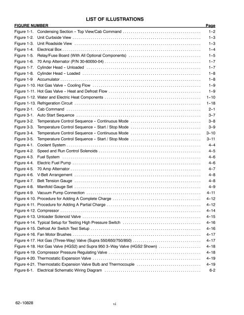
LIST OF ILLUSTRATIONSFIGURE NUMBERPageFigure 1-1. Condensing Section -- Top View/Cab Command ....................................... 1--2Figure 1-2. Unit Curbside View ................................................................ 1--3Figure 1-3. Unit Roadside View ............................................................... 1--3Figure 1-4. Electrical Box ..................................................................... 1--4Figure 1-5. Relay/Fuse Board (With All Optional Components) .................................... 1--5Figure 1-6. 70 Amp Alternator (P/N 30-60050-04) ................................................ 1--7Figure 1-7. Cylinder Head -- Unloaded ......................................................... 1--7Figure 1-8. Cylinder Head -- Loaded ........................................................... 1--8Figure 1-9 Accumulator ...................................................................... 1--8Figure 1-10. Hot Gas Valve -- Cooling Flow ...................................................... 1--9Figure 1-11. Hot Gas Valve -- Heat and Defrost Flow .............................................. 1--9Figure 1-12. Water and Electric Heat Components ................................................ 1--10Figure 1-13. Refrigeration Circuit ............................................................... 1--18Figure 2-1. Cab Command ................................................................... 2--1Figure 3-1. Auto Start Sequence .............................................................. 3--7Figure 3-2. Temperature Control Sequence -- Continuous Mode ................................... 3--8Figure 3-3. Temperature Control Sequence -- Start / Stop Mode ................................... 3--9Figure 3-4. Temperature Control Sequence -- Continuous Mode ................................... 3--10Figure 3-5. Temperature Control Sequence -- Start / Stop Mode ................................... 3--11Figure 4-1. Coolant System ................................................................... 4--4Figure 4-2. Speed and Run Control Solenoids ................................................... 4--5Figure 4-3. Fuel System ..................................................................... 4--6Figure 4-4. Electric Fuel Pump ................................................................ 4--6Figure 4-5. 70 Amp Alternator ................................................................. 4--7Figure 4-6. V-Belt Arrangement ............................................................... 4--8Figure 4-7. Belt Tension Gauge ............................................................... 4--8Figure 4-8. Manifold Gauge Set ............................................................... 4--9Figure 4-9. Vacuum Pump Connection ......................................................... 4--11Figure 4-10. Procedure for Adding A Complete Charge ............................................ 4--12Figure 4-11. Procedure for Adding A Partial Charge ............................................... 4--12Figure 4-12. Compressor ...................................................................... 4--14Figure 4-13. Unloader Solenoid Valve ........................................................... 4--15Figure 4-14. Typical Setup for Testing High Pressure Switch ....................................... 4--16Figure 4-15. Defrost Air Switch Test Setup ....................................................... 4--16Figure 4-16. Fan Motor Brushes ................................................................ 4--17Figure 4-17. Hot Gas (Three-Way) Valve (<strong>Supra</strong> <strong>550</strong>/<strong>650</strong>/<strong>750</strong>/<strong>850</strong>) .................................. 4--17Figure 4-18. Hot Gas Valve (HGS2) and <strong>Supra</strong> <strong>950</strong> 3--Way Valve (HGS2 Shown) ..................... 4--18Figure 4-19. Compressor Pressure Regulating Valve .............................................. 4--18Figure 4-20. Thermostatic Expansion Valve ...................................................... 4--19Figure 4-21. Thermostatic Expansion Valve Bulb and Thermocouple ................................ 4--19Figure 6-1. Electrical Schematic Wiring Diagram ................................................ 6-262--10828vi