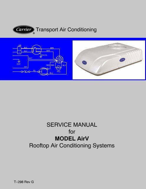
SERVICE MANUAL for MODEL AirV Rooftop Air Conditioning Systems
SERVICE MANUAL for MODEL AirV Rooftop Air Conditioning Systems
SERVICE MANUAL for MODEL AirV Rooftop Air Conditioning Systems
- No tags were found...

Create successful ePaper yourself
Turn your PDF publications into a flip-book with our unique Google optimized e-Paper software.
RTransport <strong>Air</strong> <strong>Conditioning</strong>2P12BLKBLUWHTBRNGRN/YELWHTCFHEVAP.WHTREDREDBLU1 2YELCRSBLUPTC<strong>SERVICE</strong> <strong>MANUAL</strong><strong>for</strong><strong>MODEL</strong> <strong><strong>Air</strong>V</strong><strong>Rooftop</strong> <strong>Air</strong> <strong>Conditioning</strong> <strong>Systems</strong>T--298 Rev G
<strong>SERVICE</strong> <strong>MANUAL</strong>For<strong><strong>Air</strong>V</strong>AIR CONDITIONING ANDHEATING EQUIPMENT<strong>MODEL</strong>S68RV11112A68RV11122A68RV11302A68RV14102A68RV14103A68RV14113A68RV14123A68RV15102A68RV15103A
SAFETY SUMMARYGENERAL SAFETY NOTICESThe following general safety notices supplement the specific warnings and cautions appearing elsewhere inthis manual. They are recommended precautions that must be understood and applied during operation andmaintenance of the equipment covered herein. The general safety notices are presented in the following threesections labeled: First Aid, Operating Precautions and Maintenance Precautions. A listing of the specificwarnings and cautions appearing elsewhere in the manual follows the general safety notices.FIRST AIDAn injury, no matter how slight, should never go unattended. Always obtain first aid or medical attentionimmediately.OPERATING PRECAUTIONSAlways wear safety glasses.Keep hands clear of the evaporator blower and condenser fan.No work should be per<strong>for</strong>med on the unit until all circuit breakers and start--stop switches are turned off, andpower supply is disconnected.Always work in pairs. Never work alone.In case of severe vibration or unusual noise, stop the unit and investigate.MAINTENANCE PRECAUTIONSBeware of unannounced starting of the evaporator blower & condenser fan. Do not remove the ceiling grillassembly or the upper unit cover assembly be<strong>for</strong>e turning the power off, and disconnecting the power supply.Be<strong>for</strong>e disconnecting, discharge capacitors by shorting across the capacitors terminals. (See Paragraph3.6.8)When disassembling wiring, use numbered stickers to identify wire leads and terminals. This aids in quick,accurate reassembly.Be sure power is turned off be<strong>for</strong>e working on motors, controllers, or electrical control switches. Tag any circuitbreakers and power supply to prevent accidental energizing of circuits.Do not bypass any electrical safety devices, e.g. bridging an overload, or using any sort of jumper wires.Problems with the system should be diagnosed and any necessary repairs must be per<strong>for</strong>med by qualifiedservice personnel.In case of electrical fire, open circuit switch and extinguish with CO 2 (never use water).Use dry nitrogen to pressurize the system <strong>for</strong> leak checking. Be careful not to exceed 150 psig test pressure inthe hermetic compressor.Coil fins are sharp. Use care when removing the cover <strong>for</strong>m the base pan to avoid personal injury.Oil vapor in piping stubs can ignite from torch flame and cause serious injury. Exercise extreme care whenbrazing, and keep brazing cloth and fire extinguisher handy <strong>for</strong> emergency use.Disconnect power to the <strong><strong>Air</strong>V</strong> unit be<strong>for</strong>e checking the capacitor.10/09Safety-- iT-298
SPECIFIC WARNING AND CAUTION STATEMENTSThe statements listed below are applicable to the refrigeration unit and appear elsewhere in this manual.These recommended precautions must be understood and applied during operation and maintenance of theequipment covered herein.SPECIFIC WARNINGS AND CAUTIONSWARNINGBe sure to observe warnings listed in the safety summary in the front of this manual be<strong>for</strong>eper<strong>for</strong>ming maintenance on the <strong><strong>Air</strong>V</strong> systemWARNINGBe<strong>for</strong>e working on the unit be sure to first disconnect all electric power to the unit to avoid thepossibility of electrical shock and personal injury. Be<strong>for</strong>e disconnecting, discharge capacitorsby shorting across the capacitors terminals (Refer to paragraph 3.6.8)WARNINGShield coils with cardboard to protect hands against injury from sharp metal edges when removingcompressor and other components.WARNINGOil vapor in piping stubs can ignite from torch flame and cause serious injury. Exercise extremecare when brazing, and keep brazing cloth and fire extinguisher handy <strong>for</strong> emergencyuse.WARNINGDisconnect power to the <strong><strong>Air</strong>V</strong> unit be<strong>for</strong>e checking the capacitor.WARNINGDo not touch the metal of the screwdriver when discharging the capacitor. You could receivea shock.WARNINGBe<strong>for</strong>e installing thermostat, turn off all power to unit. There may be more than one powerdisconnect. Electrical shock can cause personal injury or death.CAUTIONIn order <strong>for</strong> the <strong><strong>Air</strong>V</strong> systems to operate efficiently, a dedicated 115 Volt 20 Amp power connectionis required.T--298 Safety-- ii 10/09
CAUTIONDo not use carbon tetrachloride, solvents, or waxes containing solvents to clean plastic sections.CAUTIONCoil fins are sharp. Use care when removing the cover <strong>for</strong>m the base pan to avoid personalinjury.CAUTIONThe change from Fahrenheit to Celsius will be permanent. It cannot be changed back to Fahrenheit.CAUTIONWhen re -assembling, ensure the battery springs are correctly placed in the battery springholders.CAUTIONImproper wiring or installation may damage thermostat. Wiring must con<strong>for</strong>m to local andnational electrical codes.10/09Safety--iiiT-298
TABLE OF CONTENTSPARAGRAPH NUMBERPageSPECIFIC WARNING AND CAUTION STATEMENTS ........................................... iiSPECIFIC WARNINGS AND CAUTIONS ...................................................... iiDESCRIPTION ............................................................................... 1-11.1 INTRODUCTION ..................................................................... 1--11.2 SERIAL NUMBER IDENTIFICATION .................................................... 1--11.3 DESIGN CHANGE DESCRIPTIONS .................................................... 1--11.4 SYSTEM (UNIT) INSTALLED DIMENSIONS ............................................. 1--91.5 SERIAL NUMBER LOCATIONS ........................................................ 1--141.6 <strong><strong>Air</strong>V</strong> SYSTEM COMPONENT SPECIFICATIONS ......................................... 1--151.6.1 Refrigerant Charge ................................................................ 1--151.6.2 Compressor -- 115 Volts, 60 Cycles, 1 Phase ......................................... 1--151.6.3 Compressor -- 220 Volts, 50 Cycles, 1 Phase ......................................... 1--151.6.4 Thermostat Range (All Free Blow Units) .............................................. 1--151.6.5 Return <strong>Air</strong> Sensor (Thermistor) ...................................................... 1--151.6.6 Heat Pump Sensors (Thermistors) ................................................... 1--151.7 START--UP .......................................................................... 1--151.8 Dry Mode Function .................................................................... 1--151.9 REFRIGERANT CYCLE--STANDARD SYSTEM .......................................... 1--151.10 REFRIGERANT CYCLE -- HEAT PUMP ................................................. 1--161.10.1 Cooling .......................................................................... 1--161.10.2 Heating .......................................................................... 1--171.11 FREQUENTLY ASKED QUESTIONS AND ANSWERS .................................... 1--17TROUBLESHOOTING ......................................................................... 2-12.1 NO POWER TO UNIT ................................................................. 2--12.2 DUCTED UNIT WILL NOT OPERATE ................................................... 2--12.3 DUCTED UNIT WILL NOT COOL ....................................................... 2--12.4 COMPRESSOR POWER SUPPLY OPEN ............................................... 2--12.5 COMPRESSOR RUNS BUT CYCLES, FAN OPERATING ERRATICALLY .................... 2--12.6 CYCLES ON COMPRESSOR OVERLOAD .............................................. 2--22.7 INSUFFICIENT COOLING, COOLING AIR NOT ADEQUATE .............................. 2--22.8 CONDENSER AIR NOT ADEQUATE .................................................... 2--22.9 INSUFFICIENT COOLING ............................................................. 2--22.10 COMPRESSOR FLOODING ........................................................... 2--22.11 HEATER CYCLES ON LIMIT SWITCH (HEAT/ COOL VERSION ONLY) ..................... 2--22.12 AIR SWEEP NOT WORKING (FREE BLOW VERSION ONLY) ............................. 2--22.13 WATER LEAKAGE .................................................................... 2--22.14 INADEQUATE HEAT (FREE--BLOW HEAT ONLY) ........................................ 2--32.15 INADEQUATE HEAT (HEAT--PUMP) .................................................... 2--310/09iT--298
TABLE OF CONTENTS - Continued:<strong>SERVICE</strong> AND MAINTENANCE ................................................................ 3-13.1 PREVENTATIVE MAINTENANCE ...................................................... 3--13.2 OPERATING INSTRUCTIONS ......................................................... 3--13.3 <strong>SERVICE</strong> -- GENERAL ................................................................ 3--13.4 CEILING UNIT -- FREE BLOW SYSTEMS ............................................... 3--13.4.1 Filter Removal .................................................................... 3--13.4.2 Ceiling Grill Removal .............................................................. 3--23.4.3 Ceiling Panel Removal ............................................................. 3--23.4.4 Master Control Switch ............................................................. 3--23.4.5 <strong>Air</strong> Sweep Switch Removal ......................................................... 3--23.4.6 Indoor Thermostat Removal ........................................................ 3--33.4.7 <strong>Air</strong> Sweep Removal ............................................................... 3--33.4.8 Heat Strip Assembly Removal ...................................................... 3--33.5 CEILING UNIT -- DUCTED SYSTEMS ................................................... 3--43.5.1 Filter Removal .................................................................... 3--43.5.2 Ceiling Grill Removal .............................................................. 3--43.5.3 Control Box Assembly Removal ..................................................... 3--43.5.4 Main PCB Board Removal .......................................................... 3--53.5.5 PCB Display Removal ............................................................. 3--53.5.6 Fuse Removal .................................................................... 3--53.5.7 Dip Switch Functions .............................................................. 3--63.5.8 Return <strong>Air</strong> Thermistor .............................................................. 3--63.5.9 Heat Pump Thermistors ............................................................ 3--73.6 <strong>SERVICE</strong> -- UPPER UNIT -- STANDARD, HC & HP ....................................... 3--83.6.1 Exterior Cover Removal ............................................................ 3--83.6.2 Compressor Replacement .......................................................... 3--83.6.3 Control Box Assembly Removal ..................................................... 3--83.6.4 Upper Scroll Assembly Removal .................................................... 3--83.6.5 Motor Assembly and Condenser Fan Removal ........................................ 3--93.6.6 Evaporator Blower Wheel Adjustment or Removal ..................................... 3--103.6.7 <strong>Air</strong> Handling System Removal ...................................................... 3--103.6.8 Capacitor Troubleshooting .......................................................... 3--103.6.9 Capacitor Testing and Replacement ................................................. 3--113.6.10 Positive Temperature Coefficient Thermistor (PTC) (Start Thermistor) Troubleshooting ..... 3--113.6.11 Line Voltage -- 10% ................................................................ 3--113.7 <strong>SERVICE</strong> -- UPPER UNIT -- LOW PROFILE ............................................. 3--123.7.1 Exterior Cover Removal ............................................................ 3--123.7.2 Upper Scroll Assembly Removal .................................................... 3--123.7.3 Condenser Fan Assembly Removal .................................................. 3--133.7.4 Condenser Motor Removal ......................................................... 3--143.7.5 Evaporator Motor/Blower Assembly Removal ......................................... 3--143.7.6 Compressor Replacement .......................................................... 3--153.7.7 Capacitor Removal ................................................................ 3--153.7.8 Remote Control (Fahrenheit to Celsius) .............................................. 3--15T--298 ii10/09
TABLE OF CONTENTS - Continued:3.8 THERMOSTAT INSTALLATION AND START--UP INSTRUCTIONS (WALL MOUNTED) ....... 3--173.8.1 Introduction ...................................................................... 3--173.8.2 Installation ....................................................................... 3--173.8.3 Thermostat Location ............................................................... 3--173.8.4 Install Thermostat -- 12VDC ........................................................ 3--173.9 LCD DISPLAY ....................................................................... 3--173.9.1 Cool Only Thermostat (Part No. 1110--421) ........................................... 3--173.9.2 Heat/Cool Thermostat (Part No. 1110--420) ........................................... 3--173.10 SET THERMOSTAT CONFIGURATION ................................................. 3--173.10.1 Enter Configuration Mode .......................................................... 3--173.11 CHECK THERMOSTAT OPERATION ................................................... 3--183.11.1 Fan Operation (Cool Only) .......................................................... 3--183.11.2 Fan Operation (Heat/Cool) ......................................................... 3--183.11.3 Cooling Operation (Cool Only) ...................................................... 3--183.11.4 Cooling Operation (Heat/Cool) ...................................................... 3--183.11.5 Heating Operation (Heat/Cool) ...................................................... 3--183.12 CHECK THERMOSTAT OPERATION ................................................... 3--183.12.1 Temperature Display ............................................................... 3--183.12.2 Timeguard Timer .................................................................. 3--193.12.3 Cycle Timer ...................................................................... 3--193.12.4 Minimum On Timer ................................................................ 3--193.12.5 Error Messages ................................................................... 3--19WIRING SCHEMATICS ........................................................................ 4-14.1 INTRODUCTION ..................................................................... 4--14.2 WALL MOUNTED THERMOSTATS ..................................................... 4--64.3 WALL--MOUNTED SENSOR FOR REMOTE CONTROL ................................... 4--6LIST OF FIGURESFigure 1--1 Model/Serial Number Plate (Typical) .................................................. 1--1Figure 1--2 Roof Unit (Standard) Component Identification ......................................... 1--5Figure 1--3 Ceiling Unit Component Identification (Free--Blow) ...................................... 1--6Figure 1--4 Component Identification -- Low Profile -- Upper Unit .................................... 1--7Figure 1--5 Component Listing--Ceiling Unit For Ducted <strong>Systems</strong> .................................... 1--8Figure 1--6 Unit Dimensions -- Top View -- Upper Unit (Roof) Installed ................................ 1--9Figure 1--7 Unit Dimensions -- Standard -- Side View -- Roof + Ceiling ............................... 1--10Figure 1--8 Unit Dimensions -- Low Profile -- Side View -- Roof + Ceiling ............................. 1--11Figure 1--9 Unit Dimensions -- Ceiling Unit -- Bottom View .......................................... 1--12Figure 1--10 Ducted System <strong>Air</strong> Flow Arrangement ................................................ 1--13Figure 1--11 Serial Number Locations (Free--Blow) ................................................ 1--14Figure 1--12 Serial Number Locations (Ducted) ................................................... 1--14Figure 1--13 Refrigerant Flow Schematic (Standard System) ....................................... 1--15Figure 1--14 Refrigerant Flow Schematic -- Heat Pump -- (Cool Mode) ............................... 1--16Figure 1--15 Refrigerant Flow Schematic -- Heat Pump -- (Heat Mode) ............................... 1--1710/09iiiT--298
LIST OF FIGURES - Continued:Figure 3--1 Filter Removal -- Free Blow .......................................................... 3--1Figure 3--2 Ceiling Grill -- Free Blow ............................................................. 3--2Figure 3--3 Ceiling Panel Assembly ............................................................. 3--2Figure 3--4 Ceiling Panel With Heat Option ....................................................... 3--2Figure 3--5 Control Box Assembly -- Free Blow ................................................... 3--2Figure 3--6 Indoor Thermostat .................................................................. 3--3Figure 3--7 <strong>Air</strong> sweep motor .................................................................... 3--3Figure 3--8 Heat Strip Assembly ................................................................ 3--3Figure 3--9 Filter Removal -- Ducted Unit ......................................................... 3--4Figure 3--10 Ceiling Grill -- Ducted .............................................................. 3--4Figure 3--11 Control Box & PCB Cover .......................................................... 3--4Figure 3--12 Control Box Assembly -- Ducted ..................................................... 3--5Figure 3--13 Main/Display PCB’s ............................................................... 3--5Figure 3--14 Dip Switch Function ............................................................... 3--6Figure 3--15 Cover Assembly -- Standard ........................................................ 3--8Figure 3--16 Control Box ...................................................................... 3--8Figure 3--17 Control Box Removal .............................................................. 3--8Figure 3--18 Water Cover Removal ............................................................. 3--8Figure 3--19 Upper Scroll Assembly ............................................................. 3--9Figure 3--20 Motor Assembly ................................................................... 3--9Figure 3--21 Spring Clamp Removal ............................................................ 3--9Figure 3--22 Motor Clip Removal ............................................................... 3--9Figure 3--23 Condenser Fan Removal ........................................................... 3--10Figure 3--24 Blower Wheel ..................................................................... 3--10Figure 3--25 Condenser With Motor Assembly & Compressor ...................................... 3--10Figure 3--26 Set--Up For Discharging a Capacitor ................................................. 3--11Figure 3--27 Cover Assembly -- Low Profile ...................................................... 3--12Figure 3--28 Upper Scroll Assembly Locking Tabs (b.) & Screw Locations (c.) ......................... 3--12Figure 3--29 Upper Scroll Assembly Keeper Tab Release .......................................... 3--12Figure 3--30 Upper Scroll & Control Box Cover Removed .......................................... 3--13Figure 3--31 Condenser Fan Assembly& Retaining Ring ........................................... 3--13Figure 3--32 Condenser Fan Motor& Fan Assembly Stop .......................................... 3--13Figure 3--33 Condenser Fan Motor& Fan Assembly Tab ........................................... 3--13Figure 3--34 Condenser Motor Ground .......................................................... 3--14Figure 3--35 Evaporator Motor Locking Tabs ..................................................... 3--14Figure 3--36 Evaporator Motor/Blower Assembly ................................................. 3--14Figure 3--37 Evaporator Blower Wheel .......................................................... 3--15Figure 3--38 Control Box Assembly With Capacitor ................................................ 3--15Figure 3--39 Remote Control Components ....................................................... 3--16T--298 iv10/09
LIST OF FIGURES - Continued:Figure 3--40 Remote Control PCB (FR9 Location) ................................................. 3--16Figure 3--41 Wall Thermostat Wiring Diagram -- Cool Only Model ................................... 3--19Figure 3--42 Wall Thermostat Wiring Diagram -- Heat/Cool Model ................................... 3--20Figure 3--43 (Optional) Wall Thermostat Wiring Diagram -- Heat/Cool Model .......................... 3--21Figure 4--1 Upper Unit Schematic -- Standard & HC ............................................... 4--1Figure 4--2 Upper Unit Schematic -- Low Profile ................................................... 4--1Figure 4--3 Ceiling Unit Schematic -- Cooling Only ................................................ 4--2Figure 4--4 Ceiling Unit Schematic -- Heat/Cool ................................................... 4--2Figure 4--5 Ceiling Unit, Standard -- Ducted ...................................................... 4--2Figure 4--6 Heat Pump -- Upper Unit -- Free Blow ................................................. 4--3Figure 4--7 Heat Pump -- Ceiling Unit -- Free Blow ................................................ 4--3Figure 4--8 Heat Pump -- Upper Unit -- Standard -- Ducted ......................................... 4--4Figure 4--9 Heat Pump -- Upper Unit -- Low Profile -- Ducted ........................................ 4--4Figure 4--10 Heat Pump -- Ceiling Unit -- Ducted .................................................. 4--5Figure 4--11 Ceiling Unit -- Wall Thermostat -- Cool Only -- Ducted & Free Blow ....................... 4--5Figure 4--12 Ceiling Unit -- Wall Thermostat -- Heat/Cool -- Free Blow ............................... 4--6LIST OF TABLESTable 1--1 Model Chart ......................................................................... 1--2Table1--2<strong>MODEL</strong>CHART ..................................................................... 1--3Table 1--3 ADDITIONAL SUPPORT <strong>MANUAL</strong>S ................................................... 1--4Table 2--1 System Self--diagnostics Function (Ducted Remote) ...................................... 2--4Table 3--1 Resistance--Temperature Coefficient .................................................... 3--6Table 3--2 Resistance--Temperature Coefficient (IDC -- ODA -- ODC) ................................. 3--710/09vT--298
SECTION 1DESCRIPTION1.1 INTRODUCTIONThis manual contains service instructions and electricaldata <strong>for</strong> the <strong><strong>Air</strong>V</strong>, Carrier Transport <strong>Air</strong> <strong>Conditioning</strong>’sRecreational Vehicle air conditioning unit.The <strong><strong>Air</strong>V</strong> units are two piece systems, consisting of theUpper Unit and the Ceiling unit. The Upper Unit containsthe refrigeration system while the Ceiling Unit containsthe controls and vents. The Ceiling Units are available ina free--blow or ducted configuration.The free--blow units (see Figure 1--2) deliver air to thevehicle by means of front and rear end vents and onedownward vent (air shower). The vents may all beopened or closed to direct air as desired. The front andrear vents are fitted with motorized dampers thatoscillates to produce an “air--sweep” effect. These unitsmay be fitted with optional electric heat.The ducted units (see Figure 1--5 and Figure 1--10)deliver air through ducting built in the vehicle ceiling.These units are fitted with a 12 VDC microprocessorcontrol system, a display panel (PCB display) and aremote controller. These units may be wired to providethermostatic control of the vehicle furnace.Carrier’s <strong><strong>Air</strong>V</strong> air conditioning models include coolingonly units, heating/cooling units, and heat pump units.The cooling only units are available with free blow orducted air delivery. Cooling units with heat strips areavailable <strong>for</strong> free blow only.Operation of the <strong><strong>Air</strong>V</strong> units is controlled automatically bythe temperature controller (thermostat), whichmaintains the vehicle’s interior temperature at thedesired set point. Free Blow, cool--only units areavailable with a wall mounted thermostat.Table 1--1 lists Upper Unit <strong><strong>Air</strong>V</strong> model numbers anddescriptions. Table 1--2 lists Ceiling Unit modelnumbers and descriptions. Table 1--3 lists additionalsupport manuals that are available.1.2 SERIAL NUMBER IDENTIFICATIONSeparate part numbers and serial numbers are provided<strong>for</strong> the upper and lower unit assemblies The numbersmay be found on plates readable from inside the vehicle,See Figure 1--11 or Figure 1--12.The first two numbers of the serial number, seeFigure 3--23, is the week the unit was manufactured.For example, 01 would designate the first week of theyear and 52 would designate the last week of the year.The third and fourth numbers designate the year inwhich the unit was manufactured. For example, 99would represent the year 1999, 00 the year 2000, andso on.The letter Y and all the numbers after it designates theunit serial number. Example: Y43210A serial number of 1303Y12345 designates that the unitwas manufactured the 13th week of 2003 and the serialnumber is Y12345.<strong>MODEL</strong> No.Part No.VOLTS68RV14102A99 -00468 -01115 Vph 1 hz 60CAPACITY13,500 Btu/h3,955 W20 AMPAMPS 13.5 ATIME DELAY FUSE ORCIRCUIT BREAKER DATE OF MfgSERIAL No.05/031303Y12345DESIGN PSIG HIGH 350 LO 150R-22ozkg15.90.45COMPRESSORFAN MOTORRLAFLA12.52.58USE CEILING ASSY/ANY 99 -00469 -01Carrier<strong>Air</strong> <strong>Conditioning</strong>CDivision of Carrier CorporationUSEFigure 1 -1 Model/Serial Number Plate (Typical)1.3 DESIGN CHANGE DESCRIPTIONSThe following list provides a description of changes indesign and serial number breaks <strong>for</strong> those changes.0703Y (Power Assembly) & 1903Y (Control Assembly)New style PCB -- Cool Mode -- Control & PowerAssembly (Fans shut off in auto mode).0803Y (Power Assembly) & 2603Y (Control Assembly)New style PCB -- Heat Pump -- Control & PowerAssembly (Fans shut off in auto mode).4204Y Minimum furnace setpoint lowered from 63°Fto45°F.3808Y Changed standard profile blower wheel typefrom aluminum boss to ring compression type.10/091--1T--298
Table 1 -1 Model ChartUPPER UNIT (ROOF)<strong>MODEL</strong> NUMBER PART NUMBER CONFIGURATION VOLTAGE AMPS COLOR99--00468--00 STANDARD A/C 115/1/60 12.8 WHITE68RV14102A 99--00468--01 STANDARD A/C 115/1/60 12.8 IVORY99--00469--20 STANDARD A/C 115/1/60 12.8 BLACK68RV11302A99--00468--02 STANDARD A/C 220/1/50 5.3 COOL WHITE99--00468--03 STANDARD A/C 220/1/50 6.7 HEAT IVORY99--00468--08 HIGH--CAPACITY 115/1/60 14.1 WHITE68RV15102A 99--00468--09 HIGH--CAPACITY 115/1/60 14.1 IVORY99--00468--28 HIGH--CAPACITY 115/1/60 14.1 BLACKHEAT PUMP68RV11122AHEAT PUMP68RV11112ALOW PROFILE68RV15103ALOW PROFILE68RV14103ALOW PROFILE68RV14113ALOW PROFILE68RV14123A99--00468--0499--00468--0599--00468--2499--00468--0699--00468--0799--00468--2699--00468--1099--00468--3299--00468--1299--00468--3099--00468--1399--00468--3399--00468--11HEAT PUMPFREE--BLOWHEAT PUMPFREE--BLOWHEAT PUMPFREE--BLOWHEAT PUMPDUCTEDHEAT PUMPDUCTEDHEAT PUMPDUCTEDFREE--BLOWHIGH CAPACITYFREE--BLOWHIGH CAPACITYFREE--BLOWSTANDARDFREE--BLOWSTANDARDHEAT PUMPHIGH CAPACITYHEAT PUMPDUCTEDHEAT PUMPFREE--BLOW115/1/60115/1/60115/1/60115/1/60115/1/60115/1/60115/1/60115/1/60115/1/60115/1/60115/1/60115/1/60115/1/6012.7 COOL10.9 HEAT12.7 COOL10.9 HEAT12.7 COOL10.9 HEAT12.7 COOL10.9 HEAT12.7 COOL10.9 HEAT12.7 COOL10.9 HEAT14.1 COOL13.8 HEAT14.1 COOL13.8 HEAT13.4 COOL13.8 HEAT13.4 COOL13.8 HEAT14.5 COOL13.8 HEAT12.7 COOL10.9 HEAT12.7 COOL10.9 HEATWHITEIVORYBLACKWHITEIVORYBLACKWHITEBLACKWHITEBLACKWHITEBLACKWHITET--298 1--2 10/09
TABLE 1 -2 <strong>MODEL</strong> CHARTCEILING UNIT<strong>MODEL</strong> NUMBER PART NUMBER VOLTAGE COLOR OPTIONS INTERFACE68RV0010AA99--00469--00 115/1/60 White Cool Only Free--Blow99--00469--01 115/1/60 Ivory Cool Only Free--Blow68RV0010BA99--00469--02 115/1/60 White Heat/Cool Free--Blow99--00469--03 115/1/60 Ivory Heat/Cool Free--Blow68RV0010KA 99--00469--06 115/1/60 (12VDC) White Cool Only Ducted68RV0030AA99--00469--04 220/1/50 White Cool Only Free--Blow99--00469--05 220/1/50 Ivory Cool Only Free--Blow68RV0030BA 99--00469--08 220/1/50 White Heat/Cool Free--Blow68RV0030KA 99--00469--10 220/1/50 White Cool Only Ducted68RV0012CA99--00469--11 115/1/60 White Heat Pump Free--Blow99--00469--12 115/1/60 Ivory Heat Pump Free--Blow68RV0011LA 99--00469--13 115/1/60 (12VDC) White Heat Pump Ducted68RV0010EA 99--00469--17 115/1/60 (12VDC) White Heat/CoolFree--BlowWall Thermostat68RV0040MA 99--00469--22 115/1/60 White Cool OnlyDuctedWall Thermostat68RV0010AB(Phased Out)68RV0010BB(Phased Out)99--00469--23 115/1/60 White Cool Only Free--Blow99--00469--24 115/1/60 Ivory Cool Only Free--Blow99--00469--25 115/1/60 White Heat/Cool Free--Blow99--00469--26 115/1/60 Ivory Heat/Cool Free--BlowFree--BlowWall Thermostat68RV0010DB 99--00469--29 115/1/60 White Cool Only68RV0010EB 99--00469--31 115/1/60 White Heat/Cool68RV0012FB 99--00469--33 115/1/60 White Heat Pump68RV0010KS 99--00469--35 115/1/60 White68RV0011KS 99--00469--36 115/1/60 White68RV0010MS(Phased Out)68RV0011OS(Phased Out)99--00469--37 115/1/60 White99--00469--38 115/1/60 WhiteCool OnlyThick Roof KitHeat PumpThick Roof KitCool OnlyThick Roof KitHeat PumpThick Roof KitFree--BlowWall ThermostatFree--BlowWall ThermostatDuctedRemoteDuctedRemoteDuctedW/Wall SensorDuctedW/Wall Sensor10/091--3T--298
TABLE 1 -3 ADDITIONAL SUPPORT <strong>MANUAL</strong>S<strong>MANUAL</strong> -FORM NO. EQUIPMENT COVERED TYPE OF <strong>MANUAL</strong> (For) PART NO.71LC6A5431A <strong><strong>Air</strong>V</strong> 115 Volts--Free Blow (Cool Only) Owner’s Guide99--00469--0099--00469--0171LH6A5407A <strong><strong>Air</strong>V</strong> 115 Volts--Free Blow (Heat--Cool) Owner’s Guide99--00469--0299--00469--0371LD6A54070 <strong><strong>Air</strong>V</strong> 115 Volts--Ducted (Cool Only) Owner’s Guide 99--00469--0671LH6A5407A <strong><strong>Air</strong>V</strong> 220 Volts--Free Blow (Heat--Cool) Owner’s Guide99--00469--0899--00469--0971RQ6A5401B <strong><strong>Air</strong>V</strong> 115 Volts--Free Blow (Heat Pump) Owner’s Guide99--00469--1199--00469--1271LQ6A54010 <strong><strong>Air</strong>V</strong> 115 Volts--Ducted (Heat Pump) Owner’s Guide 99--00469--1371DW6A54070 <strong><strong>Air</strong>V</strong> 115 Volts--Ducted Wired Thermostat Owner’s Guide 99--00469--2271LC6A5431A <strong><strong>Air</strong>V</strong> 115 Volts--Free Blow (Cool Only) Owner’s Guide99--00469--2399--00469--2471LH6A5407A <strong><strong>Air</strong>V</strong> 115 Volts--Free Blow (Heat--Cool) Owner’s Guide99--00469--2599--00469--2671RW6A54310 <strong><strong>Air</strong>V</strong> 115 Volts--Free Blow Wired Thermostat Owner’s Guide 99--00469--2971LD6A54070 <strong><strong>Air</strong>V</strong> 115 Volts--Free Blow Wired Thermostat Owner’s Guide 99--00469--3571LQ6A54010 <strong><strong>Air</strong>V</strong> 115 Volts--Free Blow Wired Thermostat Owner’s Guide 99--00469--3671DJ6A54070 <strong><strong>Air</strong>V</strong> 115 Volts--Free Blow Wired Thermostat Owner’s Guide 99--00469--3771DK6A54010 <strong><strong>Air</strong>V</strong> 115 Volts--Free Blow Wired Thermostat Owner’s Guide 99--00469--38T--298PL <strong><strong>Air</strong>V</strong> Service Parts ALL62--50455--00 Basic refrigeration Service Training ALLT--298 1--4 10/09
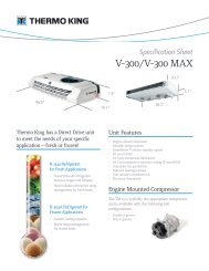
123451.2.CoverCondenser3. Evaporator4. Compressor5. Base PanFigure 1 -2 Roof Unit (Standard) Component Identification10/091--5T--298
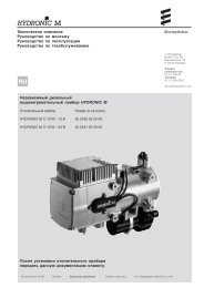
12341. Ceiling Panel Assembly2. Control Box Cover3. Control Assembly4. Ceiling Grill AssemblyFigure 1 -3 Ceiling Unit Component Identification (Free -Blow)T--298 1--6 10/09
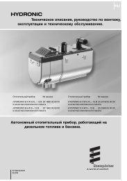
12395647810111.2.Cover AssemblyScroll Assembly -- Upper7.8.Condenser CoilScroll Assembly -- Lower3.4.Condenser FanCondenser Motor9. Evaporator Coil10. Compressor5.6.Evaporator MotorEvaporator Blower Wheel11. Base Pan AssemblySee Figure 1--3 <strong>for</strong> Ceiling Package (Free--Blow)Figure 1 -4 Component Identification - Low Profile - Upper Unit10/091--7T--298
1231211104567891.2.Telescoping Divider (3 different sizes available)Divider Assembly3.4.Frame Panel, Insulation AssemblyControl Box Assembly5.6.Control Box CoverSuction Packing Assembly7. Remote Control Assembly8. Remote Control Bracket Assembly9. Filter Assemblies (2)10. PCB Cover11. PCB Main Assembly12. PCB DisplayFigure 1 -5 Component Listing -Ceiling Unit For Ducted <strong>Systems</strong>T--298 1--8 10/09
1.4 SYSTEM (UNIT) INSTALLED DIMENSIONSRefer to Figure 1--6 thru Figure 1--9 <strong>for</strong> installation dimensions of Standard & Low Profile Upper Units & Ducted &Free--Blow Ceiling units.14” by 14”10.3”Opening16.7”22.6”4.3”4.3”41.0”ROOF UNIT - TOP VIEW - STANDARD3.6”6.4” 6.4”14” by 14”Opening24.1”26.8”41.7”ROOF UNIT - TOP VIEW - LOW PROFILEFigure 1 -6 Unit Dimensions - Top View - Upper Unit (Roof) Installed10/091--9T--298
10.3” 14” OPENING16.7”1.65” 1.65”STANDARD ROOF - DUCTED CEILING10.3” 14” OPENING16.7”3.45” 8.15”STANDARD ROOF - FREEBLOW CEILINGFigure 1 -7 Unit Dimensions - Standard - Side View - Roof + CeilingT--298 1--10 10/09
3.6”14” Opening24.1”1.65” 1.65”LOW PROFILE ROOF + DUCTED CEILING3.6” 14” Opening24.1”3.45” 8.15”LOW PROFILE ROOF + FREEBLOW CEILINGFigure 1 -8 Unit Dimensions - Low Profile - Side View - Roof + Ceiling10/091--11T--298
3.45”14” by 14”8.15”19.7”Opening2.84”2.84”1.65”FRONT1.65”14” by 14”1.65”17.3”Opening1.65”17.3”DUCTED UNITFRONT25.6”FREEBLOW UNITFigure 1 -9 Unit Dimensions - Ceiling Unit - Bottom ViewT--298 1--12 10/09
12354SCHEMATIC VIEW15SUPPLY AIR123SUPPLY AIR4INSTALLED VIEWRETURN AIR1.2.Vehicle Duct System (Connection)Telescoping Divider (3 different sizes available)3. Return <strong>Air</strong> Suction Area4. Control Box Assembly5. Supply <strong>Air</strong> Discharge AreaFigure 1 -10 Ducted System <strong>Air</strong> Flow Arrangement10/091--13T--298
1.5 SERIAL NUMBER LOCATIONSOn most applications the Serial/Model Numbers of the Upper Unit and Ceiling Unit have been recorded on theWarranty Registration Form during Installation of the <strong><strong>Air</strong>V</strong> system. In the event that Serial Numbers have not beenrecorded refer to Figure 1--11 and Figure 1--12 <strong>for</strong> the location of the Serial/Model Number tags. The ceiling unitcovers must be removed in order to see the tags. To see the Free--Blow upper unit tag you must look around the metalceiling panel. The Serial/Model Number tag <strong>for</strong> the Ducted Unit is located on the side of the control box.Serial numberof Upper UnitUpper UnitSerial Numberof Ceiling UnitFree Blow TypeCeiling Unit(Cover Removed)Figure 1 -11 Serial Number Locations (Free -Blow)Serial Number ofCeiling Unit(Side of Control Box)Ceiling Assembly FrameBottom ofUpper UnitDucted TypeSerial Numberof Upper UnitBottom View After Installation(With Grille Removed)Figure 1 -12 Serial Number Locations (Ducted)T--298 1--14 10/09
1.6 <strong><strong>Air</strong>V</strong> SYSTEM COMPONENT SPECIFI-CATIONS1.6.1 Refrigerant ChargeStandard -- High Capacity -- Heat PumpR--22 -- 15.9 OuncesLow Profile (All)R--22 -- 16.9 Ounces1.6.2 Compressor - 115 Volts, 60 Cycles, 1 PhaseNOTE<strong><strong>Air</strong>V</strong> Compressor mounting bolts must betorqued15/17 ft./lbs.1. Locked Rotor Amps - Standard - HighCapacity - Heat Pump60.0 AMPS2. Locked Rotor Amps - Low ProfileHigh Capacity59.0 AMPS3. Fully Loaded Amps - StandardCooling -- Approximate 12.8 AMPSHeating -- N/A4. Fully Loaded Amps - High CapacityCooling -- Approx. 14.1 AMPSHeating -- Approx. 11 AMPS5. Fully Loaded Amps - Low ProfileCooling -- Approx. 13.4 AMPSHeating -- Approx. 13.8 AMPS6. Fully Loaded Amps - Heat PumpCooling -- Approx. 12.9 AMPSHeating -- Approx. 13.8 AMPS1.6.3 Compressor - 220 Volts, 50 Cycles, 1 Phase1. Locked Rotor Amps23.6 AMPS1.6.4 Thermostat Range (All Free Blow Units)61° F(16° C) to 89° F(32° C)1.6.5 Return <strong>Air</strong> Sensor (Thermistor)The Return--<strong>Air</strong>--Sensor (Thermistor) is part of the PCBMain Assembly. The sensor has a yellow coating andprotrudes about 3/16 inch thru the ceiling panel wheninstalled. Refer to Table 3--1 <strong>for</strong> resistance table.1.6.6 Heat Pump Sensors (Thermistors)The Heat Pump systems have a (ODA) outdoor airthermistor and a (ODC) outdoor coil thermistor, bothlocated in the upper unit and a (IDC) indoor coilthermistor located in the ceiling unit. Resistance values<strong>for</strong> these thermistors can be found in Table 3--2.1.7 START -UPRefer to operating instructions in Owners Guide (seeTable 1--3) packaged with the vehicle system.1.8 Dry Mode FunctionThis operation effectively eliminates moisture byoperating the compressor and fan motor intermittently,so that the room temperature is maintained at settemperature. Compressor will be “on” <strong>for</strong> 5 minutes,then “off” <strong>for</strong> 5 minutes. System fan motor will operateon low speed.NOTEUnit determines Dry Mode by sensing Room Temperatureevery 5 minutes (3 minute minimum operationof compressor is not applied).DISCHARGELIQUIDSUCTIONEVAPORATORCAPILLARYTUBEACCUMULATORSTRAINERCOMPRESSORCONDENSERFigure 1 -13 Refrigerant Flow Schematic (Standard System)1.9 REFRIGERANT CYCLE -STANDARD SYSTEMThe cooling cycle is energized when the thermostat,located on the ceiling unit, calls <strong>for</strong> cooling. The maincomponents of the system are the compressor,air-cooled condenser coil, strainer, capillary tube,evaporator coil and accumulator.The compressor raises the pressure and thetemperature of the refrigerant and <strong>for</strong>ces it through thedischarge line into the condenser coil. (SeeFigure 1--13.)The condenser fan circulates surrounding air (which isat a temperature lower than the refrigerant) over theoutside of the coil tubes. Heat transfer is established10/091--15T--298
from the refrigerant (inside the tubes) to the air (flowingover the tubes). The tubes have fins designed toimprove the transfer of heat from the refrigerant gas tothe air. This removal of heat causes the refrigerant toliquefy, thus liquid refrigerant leaves the coil and flowsthrough a strainer to the capillary tube. The strainerremoves any impurities within the refrigerant system.The capillary tube meters the flow of liquid refrigerant tothe evaporator coil. As the refrigerant flows through thecapillary tube, there is a reduction in pressure andtemperature.The evaporator blower (fan) pulls vehicle air through thefilters, which remove particulate matter, and then passthe cleaned air through the evaporator coil.The low pressure, low temperature liquid that flows intothe evaporator coil tubes is colder than the air that iscirculated over the tubes. Heat transfer is establishedfrom the vehicle air (flowing over the tubes) to therefrigerant (flowing inside the tubes). The evaporatorcoil tubes have aluminum fins to increase heat transferfrom the air to the refrigerant; there<strong>for</strong>e the cooler air iscirculated to the interior of the vehicle.The transfer of heat from the air to the low temperatureliquid refrigerant in the indoor coil causes the liquid tovaporize. This low temperature, low pressure vaporpasses into the accumulator. The accumulator isdesigned with the inlet tube delivering refrigerant to thebottom of the tank and the outlet tube taking refrigerant<strong>for</strong>m the top of the tank. This arrangement ensures thatonly vapor refrigerant is returned to the compressor,where the cycle repeats.When ventilation only is selected, the indoor fanfunctions to circulate air throughout the vehicle. Therefrigerant cycle will remain off.1.10 REFRIGERANT CYCLE - HEAT PUMPDISCHARGELIQUIDSUCTIONINDOOR COILCAPILLARYTUBESTRAINERREVERSING VALVEACCUMULATORCOMPRESSOROUTDOOR COILFigure 1 -14 Refrigerant Flow Schematic - Heat Pump - (Cool Mode)1.10.1 CoolingThe cooling cycle is energized when the thermostat,located in the ceiling unit, calls <strong>for</strong> cooling The systemcontrols are positioned <strong>for</strong> “normal” refrigerant flow, withthe compressor discharge delivered to the outdoor coiland liquid delivered to the indoor coil. (SeeFigure 1--14.)The main components of the system are thecompressor, reversing valve, air-cooled outdoor coil,strainer, capillary tube, indoor coil, and the accumulator.The compressor raises the pressure and thetemperature of the refrigerant and <strong>for</strong>ces it through thedischarge line and reversing valve into the outdoor coil.The outdoor fan circulates surrounding air (which is at atemperature lower than the refrigerant) over the outsideof the coil tubes. Heat transfer is established from therefrigerant (inside the tubes) to the outdoor air (flowingover the tubes). The tubes have fins designed toimprove the transfer of heat from the refrigerant gas tothe air; this removal of heat causes the refrigerant toliquefy, thus liquid refrigerant leaves the coil and flowsthrough the strainer to the capillary tube. The strainerremoves any impurities within the refrigerant system.The capillary tube meters the flow of liquid refrigerant tothe indoor coil. As the refrigerant flows through thecapillary tube, there is a reduction in pressure andtemperature.The indoor blower (fan) pulls inside air through thefilters, which remove particulate matter, and then passthe cleaned air through the indoor coil.The low pressure, low temperature liquid that flows intothe indoor coil tubes is colder than the air that iscirculated over the tubes. Heat transfer is establishedfrom the indoor air (flowing over the tubes) to therefrigerant (flowing inside the tubes). The indoor coiltubes have aluminum fins to increase heat transfer fromthe air to the refrigerant; there<strong>for</strong>e the cooler air iscirculated to the interior of the vehicle.The transfer of heat from the air to the low temperatureliquid refrigerant in the indoor coil causes the liquid tovaporize. This low temperature, low pressure vaporT--298 1--16 10/09
passes into the accumulator. The accumulator isdesigned with the inlet tube delivering refrigerant to thebottom of the tank and the outlet tube taking refrigerant<strong>for</strong>m the top of the tank. This arrangement ensures thatonly vapor refrigerant is returned to the compressor,where the cycle repeats.When ventilation only is selected, the indoor fanfunctions to circulate air throughout the vehicle. Therefrigerant cycle will remain off.DISCHARGELIQUIDSUCTIONINDOOR COILCAPILLARYTUBESTRAINERREVERSING VALVEACCUMULATORCOMPRESSOROUTDOOR COILFigure 1 -15 Refrigerant Flow Schematic - Heat Pump - (Heat Mode)1.10.2 HeatingThe heating cycle is energized when the thermostat,located in the ceiling unit, calls <strong>for</strong> heat The systemcontrols are positioned <strong>for</strong> “reverse” refrigerant flow,with the compressor discharge delivered to the indoorcoil and liquid delivered to the outdoor coil. (SeeFigure 1--15.)The main components of the system are thecompressor, reversing valve, indoor coil, capillary tube,strainer, air-cooled outdoor coil, and the accumulator.The compressor raises the pressure and thetemperature of the refrigerant and <strong>for</strong>ces it through thedischarge line and reversing valve into the indoor coil.The indoor blower (fan) pulls inside air through thefilters, which remove particulate matter, and then passthe cleaned air through the indoor coil.The vehicle air (which is at a temperature lower than therefrigerant) passes over the outside of the coil tubes.Heat transfer is established from the refrigerant (insidethe tubes) to the vehicle air (flowing over the tubes). Thetubes have fins designed to improve the transfer of heatfrom the refrigerant gas to the air; this removal of heatcauses the refrigerant to liquefy, thus liquid refrigerantleaves the coil and flows through the strainer to theoutdoor coil. The strainer removes any impurities withinthe refrigerant system.The capillary tube meters the flow of liquid refrigerant tothe outdoor coil. As the refrigerant flows through thecapillary tube, there is a reduction in pressure andtemperature.The low pressure, low temperature liquid that flows intothe outdoor coil tubes is colder than the outdoor air thatis circulated over the tubes. Heat transfer is establishedfrom the outdoor air (flowing over the tubes) to therefrigerant (flowing inside the tubes). The outdoor coiltubes have aluminum fins to increase heat transfer fromthe air to the refrigerant.The transfer of heat from the air to the low temperatureliquid refrigerant in the outdoor coil causes the liquid tovaporize. This low temperature, low pressure vaporpasses into the accumulator. The accumulator isdesigned with the inlet tube delivering refrigerant to thebottom of the tank and the outlet tube taking refrigerant<strong>for</strong>m the top of the tank. This arrangement ensures thatonly vapor refrigerant is returned to the compressor,where the cycle repeats.When ventilation only is selected, the indoor fanfunctions to circulate air throughout the vehicle. Therefrigerant cycle will remain off.1.11 FREQUENTLY ASKED QUESTIONS ANDANSWERS1. Q) -CanaHeatStripbeaddedtoa(CoolOnly)Freelow Unit?A) No. The addition of a heat strip requires anew ceiling assembly (Pt# 99--00469--02). TheMaster Switch and Thermostat have additional functionsto accommodate heat. The Thermostat is dualposition (SPDT) contacts as opposed to single position(SPST).2. Q) - Why is the plug on the heat strip too short toreach the connector?A) The heat strip is secured <strong>for</strong> shipping purposes.Remove the heat strip, flip it over and mount itin the airflow. When properly installed in this mannerthe interface cable will reach.10/091--17T--298
3. Q) - Why will the ducted (remote control) unit runin fan and heat mode, and the green “ON” lightflash 5 times over and over?A) The system has locked out due to “CompressorCircuit” being interrupted <strong>for</strong> abnormal reasonduring operation. This can be caused by power interruptionor voltage drop (Brown--Out). Theelectronics monitors the voltage to the unit and willlock--out <strong>for</strong> safety. To ’re--set”, disconnect the 12VDC from the electronic controls <strong>for</strong> 15 seconds andre--connect. If the alarm comes back in, check the 115vac with amp meter to determine unit amp draw (withcompressor and fan running) is within specificationsaccording to unit model (Refer to Table 1--1).4. Q) - How do I know if the unit is cooling OK? Itdoesn’t seem to be cold enough.A) Check to see if filters are clean. Oncecleaned, take the temperature of the air going into thefilters and compare to the air temperature coming outof the unit (If ducted -- take reading as close as possibleto unit air outlet). The temperature difference(Delta--T) should be 20 to 25 degrees. This test requiresthe interior temperature to be warm enough toprovide a good heat load to the air conditioning system.If the interior temperature is cold, the temperaturedrop may not be as high as 20 to 25 degrees.If the temperature drop is not as described above, takean amp draw on the units 115 vac and compare to correctmodel in Table 1--1.5. Q) - When the remote controlled unit is turnedon, the compressor runs 5 minutes and thenshuts off, then repeats. You reset the 12 VDC andthe same thing keeps happening. What’s iswrong?A) There is a temperature sensor probe thatshould be inserted into the indoor (evaporator) coil attime of installation. It needs to see a temperature dropwithin 5 minutes of compressor start up to confirmproper operation. Check to see if the probe has beeninserted into the coil and if properly. Probe is 2.5 to 3inches in length with 2 brown wires (See “Owner’sGuide” that came with the system).6. Q) - The temperature on the remote control goesup 2 degree increments most of the time and 1 degreeincrements other times. Why?A) When the remote control was developed, itwas done using the Celsius scale. When converted toFahrenheit, it will stage in 2 degree (F) incrementsmost times, and occasionally kit 1 degree increment.This is normal, and cannot be changed.7. Q) - On some remote control systems the temperatureon furnace mode goes down to 63 degrees,while on another remote control systemthe temperature in furnace mode goes down to 45degrees. Why is that?A) Initially the lowest set point <strong>for</strong> furnace mode63 degrees. Starting with ceiling unit serial numbersafter 4204Y the furnace setpoint was lowered to 45degrees.NoteThe first 2 numbers in the serial number relateto the week of the year manufactured; the 3rdand 4th digits relate to the year of manufacture.Example: 4204Y was manufactured the 42ndweek of 2004.8. Q) - The Freeblow ceiling package with manualthermostat, what is the temperature range?A) The manual control Thermostat on afreeblow ceiling unit is 61 to 89 degrees F.9. Q) - The Freeblow ceiling unit fan runs all thetime, even when the compressor shuts down. Isthis normal?A) Yes, the Freeblow unit is designed to havethe fan run continuously.10. Q) - There is a red light blinking on the ductedremote control unit. What is this?A) The blinking red light indicates that 12 VDC isinstalled and powered to the unit controls. If there isno light blinking, the unit controls will not operate the115 VAC equipment.11. Q) - Is there a wall mounted thermostat availableto control a Carrier <strong><strong>Air</strong>V</strong> Heat Pump?A) No, wall mounted thermostats are only available<strong>for</strong> Freeblow and Ducted Cool Only units.12. Q) - What are the electrical requirements <strong>for</strong>each <strong><strong>Air</strong>V</strong> unit.A) Each unit should have a dedicated 20 Amp(12 gage wire with ground) protected circuit.13. Q) - The heat strip on the Freeblow unit nolonger works. Is a new one needed?A) Not necessarily. Heat strips manufacturedafter 3507Y are equipped with a manual reset overloadprotector. Remove required components to accessthe electrical connections at the heat strip assembly.On the back of the overload protector there isa “RED” reset button. Push the button in till it clicks toreset. If no reset button is present the unit was manufacturedprior to 3507Y. Check element <strong>for</strong> open circuitor resistance value of 9 Ohms.14. Q) - The remote control set temperature seemsto be off by 3 or 4 degrees from the ceiling unit.Whyisthis?A) The temperature is sensed at the ceiling unit,not at the remote control. The temperature offset canbe even more with RV’s with higher ceilings. This ismore common in heat mode, as warm air rises.T--298 1--18 10/09
SECTION 2TROUBLESHOOTINGFor ducted units, the GREEN operation indicator LED (SeeFigure 3 -9) will flash if there is a problem.Refer to Table 2 -1 <strong>for</strong> diagnostic in<strong>for</strong>mation.SYMPTOM AND PROBABLE CAUSE2.1 NO POWER TO UNITPROBABLE REMEDY1. Master switch off2. Open circuit breaker3. Defective wiring4. Loose electrical connections5. Faulty switches, thermostat, or fan6. 12 VDC not connected (Ducted System)7. 12 VDC in--line fuse open (Ducted)2.2 DUCTED UNIT WILL NOT OPERATE1. Display not illuminated2. Display illuminated2.3 DUCTED UNIT WILL NOT COOL1. Green LED light flashes 5 times2. Unit cools <strong>for</strong> a few moments then stops cooling2.4 COMPRESSOR POWER SUPPLY OPEN1. Loose leads at compressor terminals2. Defective motor overload switch3. Defective capacitor4. Open compressor windings5. Seized compressor6. Capacitor incorrectly wired1. Reset master switch2. Reset circuit breaker3. Replace wiring4. Tighten connections5. Replace defective components6. Connect to 12 VDC power source7. Replace fuse1. Check 12 Volt DC in--line fuse2. Check 115 Volt AC Connections2.5 COMPRESSOR RUNS BUT CYCLES, FAN OPERATING ERRATICALLY1. Loose lead at fan motor2. Defective or burned out motor3. Outdoor air restricted or recirculating4. Overcharge or noncondensables in system5. Restricted discharge line6. Defective motor overload switch1. Check 115 volt AC power sourceMomentarily disconnect 12 VDC power sourceDisable compressor malfunction test switch.Check AMP draw.Check ∆ T2. Remove grill, verify evaporator coil probe isinserted into coil.Check AMP draw.Check ∆ TReplace unit1. Tighten leads2. Replace switch3. Replace capacitor -- Refer to Paragraph 3.6.84. Replace compressor5. Replace compressor6. Verify capacitor wiring (Refer to wiring diagram)1. Tighten lead.2. Replace motor.3. Check <strong>for</strong> dirty condenser coil, proper clearancearound unit, remove any obstructions.4. Check AMP draw5. Check <strong>for</strong> obstruction in line.Check ∆ T.Replace unit.6. Replace switch.10-092--1T--298
SYSTEM AND PROBABLE CAUSE2.6 CYCLES ON COMPRESSOR OVERLOAD1. Defective run capacitor2. Defective compressor bearings or valves3. Greatly restricted evaporator air, iced evaporatorcoil.4. Low refrigerant charge5. Evaporator capillary restricted6. Liquid line restricted7. Compressor hot8. Weak or inconsistent line power2.7 INSUFFICIENT COOLING, COOLING AIR NOT ADEQUATE1. Dirty evaporator coil2. Iced evaporator coil, slightly low refrigerant charge3. Improper fan operation4. Defective fan motor5. Return air filter is dirty2.8 CONDENSER AIR NOT ADEQUATE1. Outside <strong>Air</strong> Restricted2. Dirty coil3. Defective fan motor2.9 INSUFFICIENT COOLING1. Unit undersized2. Capillary restricted2.10 COMPRESSOR FLOODING1. Unit overcharged2. Low evaporator airflow3. Defective electrical connectionsPROBABLE REMEDY1. Replace capacitor -- Refer to Paragraph 3.6.82. Replace unit.3. Defrost evaporator coil.4. Replace unit.5. Replace unit.6. Replace unit.7. Verify refrigerant charge.Check AMP draw.Check ∆ T.8. Check line voltage at time of compressor start--up.1. Clean as required.2. Defrost or Recharge.3. Verify fan rotation (Refer to wiring diagram)4. Replace fan motor.5. Remove and clean filters (Refer to paragraphs 3.4.1& 3.5.1)1. Check <strong>for</strong> obstruction at coil. Remedy as required.2. Clean coil.3. Replace fan motor.1. Re--evaluate unit <strong>for</strong> proper capacity.2. Check AMP draw.Check ∆ T.Replace unit.2.11 HEATER CYCLES ON LIMIT SWITCH (HEAT/ COOL VERSION ONLY)1. Dirty filter2. Blocked evaporator air inlet (indoor)3. Low airflow due to fan motor speed2.12 AIR SWEEP NOT WORKING (FREE BLOW VERSION ONLY)1. Ceiling grill not properly aligned2. Linkage in upper control box stuck3. <strong>Air</strong> sweep motor failure1. Check AMP draw.Check ∆ T.Replace unit.2. Clean filter and/or evaporator coil.3. Check connections per wiring diagram and tightenany loose connections.1. Clean or replace filter.2. Remove blockage.3. Check fan motor. Repair or replace as necessary.1. Align ceiling grill.2. Align and lubricate linkage.3. Replace motor.2.13 WATER LEAKAGE1. Water dripping from ceiling unit. 1. Verify vehicle is levelTighten unit mounting bolts evenly or replace unitgasket.T--298 2--2 10/09
SYSTEM AND PROBABLE CAUSEPROBABLE REMEDY2.14 INADEQUATE HEAT (FREE -BLOW HEAT ONLY)1. No heat from heat strip. 1. Verify AMP draw (13.8 AMP)Verify resistance through heating element. (9 OHM)Check bi--metal switch. If open, replace switch.2.15 INADEQUATE HEAT (HEAT -PUMP)NOTE: Allow unit to operate 15 minutes after switchingfrom cooling mode.1. Reversing valve not operating2. Outdoor coil icing.Clearing Diagnostic Alarms1. Check <strong>for</strong> 115 volts at reversing valve coilCheck <strong>for</strong> reversing valve restrictionVerify compressor operation2. Check outdoor coil sensorWhen a repair has been accomplished due to a corresponding alarm, the alarm must be cleared. This is doneby disconnecting the 12 VDC power to the ducted ceiling assembly <strong>for</strong> one or two seconds. Once the 12 VDCpower is reconnected, the alarm should have been cleared.10-092--3T--298
Table 2 -1 System Self -diagnostics Function (Ducted Remote)FlashesError Codes(Priority)Error Contents(Malfunction)2 1 ROOM AIR THERM-ISTOR FAILUREDisplay Pattern0.5 sec.(Twice)Allowed ModesFAN Mode3 2 INDOOR COILTHERMISTOR FAIL-URE3sec.3sec.0.5 sec (3Times)FAN ModeFURNACE Mode3sec.3sec.4 3 OUTDOOR COILTHERMISTORFAILURE0.5 sec. (4Times)FAN ModeFURNACE Mode3sec.3sec.5 4 COMPRESSORDRIVEMALFUNCTION0.5 sec. (5Times)FAN ModeFURNACE Mode3sec.3sec.6 5 REVERSING VALVEDRIVE MAL--FUNCTION0.5 sec.(6Times)FAN ModeFURNACE Mode1 6 DISCHARGE AIRTHERMISTOR FAIL-URE3sec.0.5 sec.(Once)3sec.FAN ModeFURNACE ModeContinuous 7 THERMISTORWIRING WRONG(only in coolingtest mode)3sec.3sec.0.5 sec. (Continuous)FAN Mode3sec.NOTE:If more than two errors occur, the highest ranked code is displayed. If the highest ranked error is cleared, thenext highest ranked error code is displayed.T--298 2--4 10/09
SECTION 3<strong>SERVICE</strong> AND MAINTENANCE3.1 PREVENTATIVE MAINTENANCECleaning--Clean evaporator coil and condenser coil.Hold flashlight behind coil to see if all spaces are clear.Dust accumulation obstructs or reduces airflow andresults in loss of cooling capacity. Both coils may bevacuumed when dry. Coils may also be brushed with astiff brush and then blown out with compressed air.Thoroughly clean base pan, motors, fan wheels, andother components.Clean cover and ceiling grill. Mild detergents reduceelectrostatic charges on plastic sections of the grill andare good cleaners.CAUTIONDo not use carbon tetrachloride, solvents,or waxes containing solvents to clean plasticsections.Painting--Paint any parts that show evidence of rustwith a good rust--prevention paint.Wiring - Check all wiring <strong>for</strong> deterioration and allelectrical contacts <strong>for</strong> tightness or corrosion.Mounting--Make sure unit is secure on roof accordingto installation instructions provided in Owner’s Guide.Check fans to insure that they are correctly positioned inthe center of the orifice, and tight on the shaft.Leaks--Check any connections that show evidence ofoil or leaks. When unit is properly installed (refer toOwner’s Guide) check gaskets <strong>for</strong> possible air leakage.Controls--Check unit to ensure all controls arefunctioning correctly and unit operation is normal.Vibrations can cause unwanted noise.NOTECheck to ensure that piping is not vibratingagainst side of the unit.NOTEFor proper cleaning and flushing, use a ULapproved refrigerant recovery/recyclingsystem.at 1--800--450--2211 <strong>for</strong> assistance, or to obtain theappropriate manual.3.3 <strong>SERVICE</strong> - GENERALGeneral Notes—These Service Instructions areprovided to assist the trained and qualified Carrierservice technician in repairing or replacing componentsof the <strong><strong>Air</strong>V</strong> units.WARNINGBe<strong>for</strong>e working on the unit be sure to firstdisconnect all electric power to the unit toavoid the possibility of electrical shock andpersonal injury. Be<strong>for</strong>e disconnecting, dischargecapacitors by shorting across thecapacitors terminals (Refer to paragraph3.6.8)WARNINGShield coils with cardboard to protecthands against injury from sharp metaledges when removing compressor and othercomponents.3.4 CEILING UNIT - FREE BLOW SYSTEMS3.4.1 Filter RemovalThe filters (Figure 3--1) are located in the ceiling grill. Toremove the filters, do the following:a. Grasp the edge of the filter at recess in the end of theceiling grill.b. Pull filter completely out of the filter slot.c. Vacuum filter or wash filter in luke--warm water.Shake off excess water and dry thoroughly.d. Replace filter by sliding the filter into the filter slot inthe ceiling grill until the filter frame is flush with the interiorgrill.FiltersNOTERefrigerant removal must always includerecovering the refrigerant, not allowing it toescape to the atmosphere.3.2 OPERATING INSTRUCTIONSSystem operating instructions, along with installationinstructions are included in the <strong>Air</strong> V “Owner’s Guide”,which is supplied with all Carrier Transport <strong>Air</strong> Vsystems. If the “Owner’s Guide” is not with the <strong>Air</strong> Vsystem contact Carrier Transport A/C Service Hot LineFigure 3 -1 Filter Removal - Free Blow10/093--1T--298
3.4.2 Ceiling Grill RemovalTo remove the ceiling grill (Figure 3--2) do the following:a. Be<strong>for</strong>e working on unit place the master switch in theOFF position and disconnect all electrical power.b. Remove 4 screws located on the ceiling grill, makingsure to support the weight of the grill.c. Lower the ceiling grill from the ceiling panel.d. To replace the grill, place the grill up against the ceilingpanel and align the screw holes in the grill with theceiling panel.e. Replace 4 screws.Heat StripConnectionHeater AssemblyOptionFigure 3 -4 Ceiling Panel With Heat Option3.4.4 Master Control SwitchMountingScrewsFigure 3 -2 Ceiling Grill - Free Blow3.4.3 Ceiling Panel RemovalTo remove the ceiling panel (Figure 3--3) do thefollowing:a. Remove the ceiling grill. (Refer to paragraph 3.4.2.)b. Remove 5 screws securing the duct plate to the ceilingpanel.c. Remove 4 mounting bolts making sure to support theweight of the ceiling panel.d. Disconnect the unit harnesses and main power wiresfrom the ceiling panel.e. Lower the ceiling panel from the air conditioning unit.f. Reverse above procedure <strong>for</strong> reassembly.<strong>Air</strong> Sweep CamTo remove the master control switch, do the following:a. Remove ceiling grill. (Refer to paragraph 3.4.2.)b. Remove 5 screws that secure the control assembly(Item 2, Figure 1--3) to the control box cover.c. Remove the master control switch knob by grabbingthe outside edge of the knob and pulling it off of theswitch stem.d. Remove 2 screws securing the master control switchto the control assembly.e. Carefully disconnect wires from the master controlswitch. Label wires to aid in reassembly.f. Reverse above procedure <strong>for</strong> reassembly.Junction BoxWith CoverThermostat<strong>Air</strong> Sweep SwitchMaster ControlSwitchDuct Plate &Mounting HolesSerial/ModelNumber TagMounting BoltsJunction BoxFigure 3 -3 Ceiling Panel AssemblyFigure 3 -5 Control Box Assembly - Free Blow3.4.5 <strong>Air</strong> Sweep Switch RemovalTo remove the air sweep switch, do the following:a. Remove ceiling grill. (Refer to paragraph 3.4.2.)b. Remove 5 screws securing the control assembly(Item 2, Figure 1--3) to the control box cover.c. Disconnect wires from the air sweep switch.d. Pinch tabs on either end of the switch and slide out oflower control box cover.e. Reverse above procedure <strong>for</strong> reassembly.T--298 3--2 10/09
3.4.6 Indoor Thermostat RemovalTo remove the indoor thermostat (Figure 3--6) do thefollowing:a. Remove ceiling grille. (Refer to paragraph 3.4.2.)b. Remove 5 screws securing the control assembly(item 3, Figure 1--3) to the control box cover.c. Remove the indoor thermostat knob by grabbing theoutside edge of the knob and pulling it off of the thermostatstem.d.Remove 2 screws that secure the indoor thermostat tothe lower control box cover.e. Carefully disconnect the 2 wires from the indoor thermostat.f. Remove the sensing bulb from the plastic clip.g. Carefully slide the sensing bulb through the rubbergrommet.h. Remove the thermostat from the control assembly.i. Reverse above procedure <strong>for</strong> reassembly.Thermostat<strong>Air</strong> Sweep MotorFigure 3 -7 <strong>Air</strong> sweep motor3.4.8 Heat Strip Assembly RemovalTo remove the heat strip assembly (Figure 3--8) do thefollowing:a. Remove ceiling grille. (Refer to paragraph 3.4.2.)b. Unplug electrical connection at air sweep motor assembly.c. Remove two screws securing heat strip assembly tothe ceiling panel assembly.d. Slide heat strip assembly away from air sweep motorassembly and pull down, easing the the electricalconnection through the access hole.e. Reverse the procedures <strong>for</strong> reassembly.Sensing BulbFigure 3 -6 Indoor Thermostat3.4.7 <strong>Air</strong> Sweep RemovalTo remove the air sweep, do the following:a. Remove ceiling grille. (Refer to paragraph 3.4.2.)b. Remove cam (See Figure 3--3) from air sweep motorshaft.c. Remove 4 screws securing air sweep motor bracketto the ceiling panel assembly.d. Carefully disconnect air sweep motor wire terminations.e. Remove 2 screws securing air sweep motor(Figure 3--7) to control box and remove motor.f. Reverse above procedure <strong>for</strong> reassembly.Heat StripFigure 3 -8 Heat Strip Assembly10/093--3T--298
3.5 CEILING UNIT - DUCTED SYSTEMS3.5.1 Filter RemovalThe filters (Figure 3--9) are located in the ceiling grill. Toremove the filters, do the following:a. Grasp the edge of the filter at recess in the end of theceiling grill.b. Pull filter completely out of the filter slot.c. Vacuum filter or wash filter in luke--warm water.Shake off excess water and dry thoroughly.d. Replace filter by sliding the filter into the filter slot inthe ceiling grill until the filter frame is flush with the interiorgrill.c. Remove two screws securing control box cover tocontrol box assembly. See Figure 3--11.d. Remove control box assembly cover.Mounting ScrewsOperation IndicatorsFiltersFigure 3 -9 Filter Removal - Ducted Unit3.5.2 Ceiling Grill RemovalTo remove the ceiling grill (Figure 3--10) do the following:a. Be<strong>for</strong>e working on unit place the master switch in theOFF position and disconnect all electrical power.b. Remove filters (Refer to paragraph 3.4.1).c. Remove 4 screws located on the ceiling grill, (two areunder the filters) making sure to support the weight ofthe grill.d. Lower the ceiling grill from the ceiling panel.e. To replace the grill, place the grill up against the ceilingpanel and align the screw holes in the grill with theceiling panel.f. Replace 4 screws and 2 filters.3.5.3 Control Box Assembly RemovalTo remove the control box assembly (Figure 3--11 &Figure 3--12) do the following:a. Remove ceiling grill. Refer to paragraph 3.5.2.b. Disconnect 115 volt (AC) and 12 volt (DC) powerwires.Figure 3 -10 Ceiling Grill - Ductede. Disconnect blue furnace wires.f. Unplug two connectors from upper unit.g. Unplug DC power plug #1 (red/yellow/black wires)See Figure 3--12h. Unplug relay signal plug #2 (brown/red/orange/yellow wires). See Figure 3--12i. While supporting control box assembly remove twoscrews securing control box assembly to ducted ceilingunit.j. Pull control box assembly from the ducted ceiling unit.k. Reverse above procedure to reassemble.Control BoxFusePCB CoverControl BoxCover ScrewsPCB CoverScrewsFigure 3 -11 Control Box & PCB CoverT--298 3--4 10/09
115V AC12V DCPCB DisplayHolding ClipsFuse#1PCB MainUpper UnitConnectors#2FurnaceWires (blue)#4Figure 3 -12 Control Box Assembly - Ducted3.5.4 Main PCB Board RemovalTo remove the Main PCB board (Figure 3--13) do thefollowing:a. Remove ceiling grill. Refer to paragraph 3.5.2.b. Remove three screws securing the PCB cover to theducted ceiling unit.c. Carefully turn over the PCB cover exposing the PCBmain and the PCB display assemblies.d. Gently push holding clip away from PCB main assembly.e. Lift PCB main assembly from PCB cover assembly.f. Unplug display wiring plug #4. Figure 3--13g. Unplug thermistor/thermostat wiring plug #3.Figure 3--13h. Unplug power wiring plug #1. Figure 3--12i. Unplug signal wiring plug #2. Figure 3--12j. Reverse above procedures <strong>for</strong> reassembly.Figure 3 -13 Main/Display PCB’s3.5.5 PCB Display RemovalTo remove the PCB display assembly (Figure 3--13) dothe following.a. Remove ceiling grill. Refer to paragraph 3.5.2.b. Push large clip away from PCB display assembly.c. Push center clip towards large clip.d. Pull PCB display assembly from PCB cover.e. Unplug display wiring from PCB main assembly.f. Reverse above procedures of reassembly.3.5.6 Fuse RemovalTo remove the fuse (Figure 3--11) do the following:a. Remove ceiling grill. Refer to paragraph 3.5.2.b. Turn fuse holder in direction of arrow (counter-- clock--wise).c. Pull fuse from fuse holder.d. Test and/or replace.e. Reverse above procedures <strong>for</strong> reassembly.#310/093--5T--298
3.5.7 Dip Switch FunctionsThe Ducted Ceiling unit has 5 dip switches on the main(PCB) circuit board. Dip Switches are pre--set (default)Dip SWNo.FJ#On PCBFunctionsat the factory. This section is <strong>for</strong> in<strong>for</strong>mation purposesonly. A description of the Dip Switch operation follows.Logic =LowFJ OpenLogic=HighFJ CloseDefault(Factory Setting)1 FJ1 Address Configuration DCCA DCCB DCCA2 FJ2 Compressor drive malfunction test Enabled Disabled Enabled3 FJ3 ODAT conditions <strong>for</strong> SLO mode Cooler Warmer Cooler4 FJ4 System limited operation mode (HP) Enabled Disabled Enabled5 FJ5 Defrost operation mode (Heat Pump) Enabled Disabled EnabledSystem Limited Operation Mode (SLO Mode) according to Outdoor <strong>Air</strong> Temperature (ODAT)System LimitedOperation ModeStart Conditions(Furnace Mode)Release Conditions(Heat Pump Mode)FJ3 Selection (Cooler -- Warmer)CoolerWarmerLess than or equal to 4° C (39.2° F) Less than or equal to 7° C (44.6° F)Greater than or equal to 6° C (42.8° F) Greater than or equal to 9° C (48.2° F)Figure 3 -14 Dip Switch Function3.5.8 Return <strong>Air</strong> Thermistor1. Remove 4 screws from ceiling cover.The Return--<strong>Air</strong> Sensor (Thermistor 12--50084--00) is 2. Remove 3 screws holding PCB cover.located in the ceiling assembly. The sensor has a yellow3. Un--plug thermistor plug from PC board.coating and protrudes about 3/16 inch from the ceilingpanel. To check resistance do the following:4. Check thermistor resistance. Refer to Table 3--1.Table 3 -1 Resistance -Temperature Coefficient° C ° F Resistance (K -Ohms) ° C ° F Resistance (Ohms)5 41.0 12.07 25 77.0 5.3696 43.0 11.57 26 78.5 5.1687 44.5 11.09 27 80.0 4.9768 46.5 10.63 28 82.5 4.7929 48.0 10.19 29 84.0 4.61610 50.0 9.771 30 86.0 4.44711 52.0 9.373 31 87.5 4.28612 53.5 8.993 32 89.5 4.13113 55.5 8.631 33 91.5 3.98214 57.0 8.286 34 93.0 3.84015 59.0 7.956 35 95.0 3.70316 61.0 7.641 36 96.5 3.57317 62.5 7.341 37 98.5 3.44718 64.5 7.054 38 100.5 3.32619 66.0 6.779 39 102.0 3.21120 68.0 6.517 40 104.0 3.10021 69.5 6.267 41 105.5 2.99322 71.5 6.027 42 107.5 2.89023 73.5 5.798 43 109.5 2.79224 75.0 5.579 44 111.0 2.698T--298 3--6 10/09
3.5.9 Heat Pump ThermistorsOn the Heat Pump <strong>Systems</strong> the IDC (InDoor CoilThermistor) is located in the ceiling unit. The ODA(OutDoor <strong>Air</strong> Thermistor) and the ODC (OutDoor CoilThermistor) is located in the Upper Unit. To check theresistance of these thermistors at a set temperaturerefer to Table 3--2.Table 3 -2 Resistance -Temperature Coefficient (IDC - ODA - ODC)° C ° F Resistance (K -Ohms) ° C ° F Resistance (Ohms)0 32.0 32.62 36 97.0 6.271 34.0 31.00 37 99.0 6.022 36.0 29.48 38 100.0 5.783 37.0 28.03 39 102.0 5.554 39.0 26.67 40 104.0 5.335 41.0 25.38 41 106.0 5.126 43.0 24.16 42 108.0 4.927 45.0 23.01 43 109.0 4.738 46.0 21.91 44 111.0 4.559 48.0 20.88 45 113.0 4.3710 50.0 19.90 46 115.0 4.2011 52.0 18.97 47 117.0 4.0412 54.0 18.09 48 118.0 3.8913 55.0 17.25 49 120.0 3.7514 57.0 16.46 50 122.0 3.6115 59.0 15.71 51 124.0 3.4716 61.0 15.00 52 126.0 3.3417 63.0 14.32 53 127.0 3.2218 64.0 13.68 54 129.0 3.1019 66.0 13.07 55 131.0 2.9920 68.0 12.49 56 133.0 2.8821 70.0 11.94 57 135.0 2.7822 72.0 11.42 58 136.0 2.6823 73.0 10.92 59 138.0 2.5824 75.0 10.45 60 140.0 2.4925 77.0 10.00 61 142.0 2.4126 79.0 9.57 62 144.0 2.3227 81.0 9.17 63 145.0 2.2428 82.0 8.78 64 147.0 2.1629 84.0 8.41 65 149.0 2.0930 86.0 8.06 66 151.0 2.0231 88.0 7.72 67 153.0 1.9532 90.0 7.40 68 154.0 1.8833 91.0 7.10 69 156.0 1.8234 93.0 6.90 70 158.0 1.7635 95.0 6.53 71 160.0 1.7010/093--7T--298
3.6 <strong>SERVICE</strong> - UPPER UNIT - STANDARD,HC&HP3.6.1 Exterior Cover RemovalCAUTIONCoil fins are sharp. Use care when removingthe cover <strong>for</strong>m the base pan to avoid personalinjury.Control BoxScrewsTo remove the exterior cover, do the following:a. Be<strong>for</strong>e working on unit place the master switch in theOFF position and disconnect all electrical power.b. Remove 15 screws securing the unit cover to thebase pan assembly. See Figure 3--15.c. Carefully lift the exterior cover off of the unit base panassembly.d. Reverse above procedure <strong>for</strong> reassembly.WaterCoverFigure 3 -16 Control BoxCover ScrewsFigure 3 -15 Cover Assembly - Standard3.6.2 Compressor ReplacementReplacement of the <strong><strong>Air</strong>V</strong> compressor (standard or lowprofile), during Carrier Transport A/C standard two (2)year limited warranty is not recommended.The recommended procedure is to replace the entireupper unit.Many service centers, dealers and/or distributors lackthe necessary equipment, certification and skillsnecessary to per<strong>for</strong>m the replacement satisfactorily.Compressor replacement after the warranty period isleft up to the service center, though Carrier TACrecommends the Upper Unit be replaced.3.6.3 Control Box Assembly RemovalTo remove the control box assembly, do the following:a. Remove exterior cover assembly. Refer to paragraph3.6.1.b. Remove 2 screws securing control box assembly tothe lower scroll assembly. (SeeFigure 3--16.)Figure 3 -17 Control Box Removalc. Slide control box out of the lower scroll assembly.(See Figure 3--17.)d. To open control box remove 2 screws securing thewater cover to the control box cover.e. Gently lift the water cover off of the control box. (SeeFigure 3--18.)f. Reverse above procedure <strong>for</strong> reassembly.Control BoxCoverFigure 3 -18 Water Cover Removal3.6.4 Upper Scroll Assembly Removala. Remove exterior cover assembly. Refer to paragraph3.6.1.b. Remove 4 screws securing upper scroll assembly tothe lower scroll assembly. (See Figure 3--19)T--298 3--8 10/09
c. Gently pry 4 snap clips open and lift the upper scrollassembly off of the lower scroll assembly.d. Reverse above procedure <strong>for</strong> reassembly.j. Remove motor assembly.k.Reverse above procedure <strong>for</strong> reassembly.Screws4 PlacesMotor GroundLeadGround screwFigure 3 -20 Motor AssemblySnap Clip4 PlacesSpring ClampFigure 3 -19 Upper Scroll Assembly3.6.5 Motor Assembly and Condenser FanRemovala. Remove exterior cover assembly. Refer to paragraph3.6.1.b. Remove control box assembly. Refer to paragraph3.6.3.c. Remove upper scroll assembly. Refer to paragraph3.6.4.d. Remove 4 screws securing the condenser cover tothe condenser orifice. (See Figure 3--25.)e. Carefully disconnect motor wire terminations fromwithin the control box.f. Remove 1 screw securing the motor ground lead tothe motor bracket assembly. (See Figure 3--20)g. Using flat--nosed pliers, depress the motor springclamp and slide it off of the condenser fan (SeeFigure 3--21).h. Lift and slide motor towards evaporator coil to removecondenser fan from the motor shaft.i. Remove condenser fan from motor shaft and lift fanout through the top of the condenser orifice. (SeeFigure 3--23)Figure 3 -21 Spring Clamp RemovalMotor ClipFigure 3 -22 Motor Clip Removal10/093--9T--298
Condenser FanFigure 3 -23 Condenser Fan Removal3.6.6 Evaporator Blower Wheel Adjustment or Removala. Remove exterior cover assembly. Refer to ExteriorCover Assembly Removal instructions 3.6.1b. Remove control box assembly. Refer to Control BoxAssembly Removal instructions 3.6.3c. Remove upper scroll assembly. Refer to Upper ScrollAssembly Removal instructions 3.6.4d. Loosen motor assembly. Refer to Motor AssemblyRemoval instructions 3.6.5.e. Mark shaft at a point where wheel hub and motorshaft meet to aid in reassembly.(See Figure 3--24.)f. Remove 1 set screw holding the blower wheel to themotor shaft. (See Figure 3--24)g. Slide off blower wheel from motor shafth. Reverse above procedure <strong>for</strong> reassembly.b. Remove control box assembly. Refer to paragraph3.6.3.c. Remove upper scroll assembly. Refer to paragraph3.6.4.d. Remove motor assembly. Refer to paragraph 3.6.5.e. Remove 8 screws securing lower scroll assembly tothe base pan assembly.f. Remove 1 screw from clamp securing suction tube tothe base pan assembly.g. Remove 3 nuts securing the compressor to the basepan assembly.h. Remove 2 screws securing the condenser orifice tothe base pan assembly.i. Remove 2 screws securing the condenser coil assemblyto the base pan assembly.j. Carefully lift the entire assembly off of the base panassembly.k. Reverse the above procedure <strong>for</strong> reassembly, ensuringthat the air handling system is positioned correctly.Tighten all screws.Condenser CoverCondenserCover ScrewsCompressorMotor AssemblySet ScrewBase PanFigure 3 -25 Condenser With Motor Assembly &Compressor3.6.8 Capacitor TroubleshootingWARNINGDisconnect power to the <strong><strong>Air</strong>V</strong> unit be<strong>for</strong>echecking the capacitor.Figure 3 -24 Blower Wheel3.6.7 <strong>Air</strong> Handling System Removala. Remove exterior cover assembly. Refer to paragraph3.6.1.To test capacitor to determine if good, open or shorted,an ohm meter can be used. To determine a capacitor’scapacitance, a capacitor meter is required.Capacitors showing signs of leaks or bulging should bereplaced immediately.T--298 3--10 10/09
3.6.9 Capacitor Testing and ReplacementCapacitors must be discharged properly be<strong>for</strong>e testing.a. Place a 20,000 ohm, 2 watt resistor across the terminalsof the capacitor <strong>for</strong> approximately 30 seconds(See Figure 3--26 <strong>for</strong> a suggested tool).WARNINGDo not touch the metal of the screwdriverwhen discharging the capacitor. You couldreceive a shock.b. After the capacitor has been discharged and all wiresremoved from the capacitor terminals, use an ohm--meter to test its resistance.c. Set the scale to R x 1K or 10K ohm and place theohmmeter leads across the capacitor terminals.d. If the ohmmeter first reads 0, then rises toward infinityor some higher resistance, the capacitor is good.e. If the ohmmeter goes to 0 or a low resistance andstays there, the capacitor is shorted and needs to bereplaced.f. If the ohmmeter reads infinity (OL) the capacitor isopen and needs to be replaced.INSULATED SCREWDRIVER20,000 - OHM2 - WATT RESISTORATTACH TO CLEAN UNPAINTEDMETAL PART OF UNIT FRAMECLIP TOSCREWDRIVERTOUCH TO CAPACITOR TERMINALSTO DISCHARGE CAPACITORFigure 3 -26 Set -Up For Discharging a Capacitor3.6.10 Positive Temperature Coefficient Thermistor(PTC) (Start Thermistor) Troubleshootinga. Disconnect power from the <strong><strong>Air</strong>V</strong> unit.b. Disconnect the wires to the PTC.c. Using an ohm meter, check <strong>for</strong> continuity across thePTC.If the PTC does not have continuity, it must be replaced.If continuity exists, reconnect the wires to the PTC.d. Reconnect power to the <strong><strong>Air</strong>V</strong> unit.e. Turn on the <strong><strong>Air</strong>V</strong> unit to start.f. Use a clamp--on amp probe to monitor the amp drawof the compressor during its start--up.When the compressor starts, an amp draw will beindicated <strong>for</strong> almost a second.If no amp draw is indicated or if the amp draw occurs <strong>for</strong>much longer than a second, the PTC is defective andmust be replaced.3.6.11 Line Voltage - 10%Line voltage should be checked during peak electricalload periods.With the <strong><strong>Air</strong>V</strong> unit on and the compressor operating, usea voltmeter to check the voltage being supplied to the<strong><strong>Air</strong>V</strong> unit. The voltage must be within 10% of the unitsrequired voltage. A voltage drop greater than 10% willcause a premature compressor failure and needs to becorrected immediately.10/093--11T--298
3.7 <strong>SERVICE</strong> - UPPER UNIT - LOW PROFILE3.7.1 Exterior Cover RemovalCAUTIONb. b.Coil fins are sharp. Use care when removingthe cover <strong>for</strong>m the base pan to avoid personalinjury.b.b.To remove the exterior cover, do the following:a. Be<strong>for</strong>e working on unit place the master switch in theOFF position and disconnect all electrical power.b. Remove (8) screws securing the unit cover to thebase pan assembly. See Figure 3--27.c. Carefully lift the exterior cover off of the unit base panassembly.d. Reverse above procedure <strong>for</strong> reassembly.b. b.c.Figure 3 -28 Upper Scroll AssemblyLocking Tabs (b.) & Screw Locations (c.)ScrewsScrewsFigure 3 -27 Cover Assembly - Low Profile3.7.2 Upper Scroll Assembly RemovalTo remove the upper scroll assembly, do the following:a. Remove exterior cover assembly. Refer to paragraph3.7.1.b. Release the (2) front, (2) rear, (1) left side and (1) rightside locking tabs (See Figure 3--28) by pulling backon the tabs (See Figure 3--29).c. Remove the screw (1) from the control box cover(See Figure 3--28).d. With all (6) locking tabs released and control boxscrew removed, lift the upper scroll assembly off ofthe lower scroll assembly.e. Reverse above procedure <strong>for</strong> reassembly. Ensure all(6) locking tabs snap shut & lock.Figure 3 -29 Upper Scroll AssemblyKeeper Tab ReleaseT--298 3--12 10/09
Evaporator CoilRetainingRingFigure 3 -31 Condenser Fan Assembly& Retaining RingFan StopCondenser Coil13MMBoltCondenser Motor13MMBoltGrommetFigure 3 -30 Upper Scroll & Control BoxCover Removed3.7.3 Condenser Fan Assembly RemovalFigure 3 -32 Condenser Fan Motor& Fan Assembly StopTo remove condenser fan assembly, do the following:a. Per<strong>for</strong>m steps outlined in Section 3.7.2.b. Depress and remove Retaining Ring (SeeFigure 3--31).Tabc. Using both hands, carefully pull up on fan assemblyuntil it is free of the motor shaft.d. When replacing the fan assembly make sure the fanassembly is against the stop on the shaft (SeeFigure 3--32)e. Push back on tab to allow fan assembly to restagainst stop (See Figure 3--33). Fan assembly willnow be flush with the end of the motor shaft.f. Reverse above procedure <strong>for</strong> reassembly.Figure 3 -33 Condenser Fan Motor& Fan Assembly Tab10/093--13T--298
3.7.4 Condenser Motor RemovalTo remove condenser fan motor, do the following:a. Per<strong>for</strong>m steps outlined in Section 3.7.2.b. Remove (3) 13MM bolts (See Figure 3--32).c. Remove (3) Grommets. Inspect, replace or reuse.d. Cut Tie--Wraps & discard (2 locations). When reassembling,tie--wrap at same 2 locations.e. Remove ground wire from compressor bracket (SeeFigure 3--34).f. Un--plug (yellow/brown/white) from control box assembly.g. Reverse above procedure <strong>for</strong> reassembly.Blower Side Locking TabsCond. MotorGround ScrewOutside Locking TabsComp. Mounting BoltFigure 3 -34 Condenser Motor Ground3.7.5 Evaporator Motor/Blower AssemblyRemovalTo remove the evaporator motor, do the following:a. Per<strong>for</strong>m steps outlined in Section 3.7.2.b. Pull back on and release the (4) locking tabs. Thereare 2 on each side of the control box assembly. (SeeFigure 3--35).c. Lift control box assembly from lower scroll assembly,exposing evaporator motor.d. Un--plug (black/blue/white/brown) evaporator motorfrom control box assembly.e. Remove ground wire (green/yellow) from motorhousing.f. Lift motor/blower assembly from lower scroll assemblycradle.g. Carefully remove the blower wheel from the evaporatormotor shaft by pushing out from the motor side.Figure 3 -35 Evaporator Motor Locking TabsLower ScrollAssemblyCradleCapacitorFigure 3 -36 Evaporator Motor/Blower AssemblyIn CradleT--298 3--14 10/09
NOTEWhen reassembling the blower wheel on tothe motor shaft ensure that the blowerwheel is flush with the end of the motorshaft (SeeFigure 3--37).h. Reverse above procedure <strong>for</strong> reassembly.NOTEWhen placing the evaporator motor/blowerassembly back into the lower scroll assemblycradle, make sure that the assembly isseated securely in the cradle.(See Figure 3--36).3.7.6 Compressor ReplacementPer<strong>for</strong>m the procedures outlined in Section 3.6.2There are 4 bolts with the Low Profile Compressor.The system charge <strong>for</strong> the Low Profile unit is 16.9 OZ.3.7.7 Capacitor RemovalTo remove the capacitor, do the following:Wheel Flush With Motor ShaftFigure 3 -37 Evaporator Blower Wheel(Flush With End Of Motor Shaft)a. Per<strong>for</strong>m steps a., b. & c. as outlined in Section 3.7.5.b. Per<strong>for</strong>m steps outlined in Sections 3.6.8 & 3.6.9.c. The Low Profile Capacitor is removed from the controlbox assembly by pushing on the capacitor fromunder the control box assembly (See Figure 3--36).Upper Scroll AssemblyControl Box AssemblyCapacitorTerminal BlockFigure 3 -38 Control Box Assembly With Capacitor3.7.8 Remote Control (Fahrenheit to Celsius)All Remote Control Assemblies in the United States arepre--set to display in Fahrenheit degrees (seeFigure 3--39). To change from a Fahrenheit display to aCelsius display do the following:CAUTIONThe change from Fahrenheit to Celsius willbe permanent. It cannot be changed back toFahrenheit.10/093--15T--298
a. Remove the batteries from the remote control.b. Carefully remove the remote cover by inserting a narrowflat object between the cover and remote bodyand prying apart.c. Remove the brass screw holding the PCB in place.d. Carefully remove the PCB board from the remotebody, making sure the battery springs release fromtheir holders.e. Locate FR9 on the PCB board (see Figure 3--40).f. Carefully cut the FR9 jumper wire.g. Reverse above procedure <strong>for</strong> reassembly.CAUTIONWhen re -assembling, ensure the batterysprings are correctly placed in the batteryspring holders.BATTERIES&COVERBattery SpringsPCBSpring HoldersCOVERBODYFigure 3 -39 Remote Control ComponentsPCBFR9Figure 3 -40 Remote Control PCB (FR9 Location)T--298 3--16 10/09
3.8 THERMOSTAT INSTALLATION AND START -UP INSTRUCTIONS (WALL MOUNTED)3.8.1 IntroductionThe thermostat is a wall mounted, low--voltagethermostat which maintains room temperature bycontrolling the operation of a heating and airconditioning system. Temperature and mode settingsare preserved with the power off. Refer to Figure 3--41<strong>for</strong> Cool Only wiring diagram and Figure 3--42 orFigure 3--43 <strong>for</strong> Cool/HeatCAUTIONImproper wiring or installation may damagethermostat. Wiring must con<strong>for</strong>m to localand national electrical codes.WARNINGBe<strong>for</strong>e installing thermostat, turn off allpower to unit. There may be more than onepower disconnect. Electrical shock cancause personal injury or death.3.8.2 InstallationNOTERead all instructions be<strong>for</strong>e starting the installation.NOTEThe thermostat requires no batteries. The thermostatis not a power stealing device andMUST have both R and C connected.3.8.3 Thermostat LocationThe thermostat should be mounted:Approximately 5 foot (1.5m) from the floor.Close to or in a frequently used room, preferably onan inside partitioning wall.On a section of wall without pipes or duct work.The thermostat should NOT be mounted:Close to a window, or an outside wall, or next to a doorleading to the outside.Exposed to direct light and heat from a lamp, sun, fireplace,or other temperature--radiating object whichmay cause a false reading.Close to or in direct airflow from supply registers andreturn--air grilles.In areas with poor air circulation, such as behind adoor or in an alcove.3.8.4 Install Thermostat - 12VDCa. Turn off all power to unit.b. If an existing thermostat is being replaced:1.Remove existing thermostat from wall.2.Disconnect wires from existing thermostat, one ata time. Be careful not to allow wires to fall back intothe wall.3.As each wire is disconnected, record wire colorand terminal marking.4.Discard or recycle old thermostat.NOTEMercury is a hazardous waste and must be disposedof properly.c. Separate the front and back pieces of plastic.d. Route thermostat wires through hole in back piece ofplastic. Level plastic against wall (<strong>for</strong> aesthetic valueonly -- thermostat need not be leveled <strong>for</strong> proper operation)and mark wall through 2 mounting holes.e. Drill two 3/16 inch mounting holes in wall wheremarked.NOTEMounting holes on thermostat are designed tofit on a horizontal J--Box.f. Secure back plastic to wall with 2 anchors and screwsprovided, making sure all wires extend through hole inplastic.g. Connect wires to proper terminal of the connectorblock in the front piece of plastic.h. Push any excess wire back into wall. Excess wire insidethe thermostat plastic case can interfere withproper air flow across the temperature sensor. Sealhole in wall to prevent air leaks. Leaks can effect operation.i. Snap front and back pieces of plastic together.j. Turn on power to the unit.3.9 LCD DISPLAY3.9.1 Cool Only Thermostat (Part No. 1110 -421)On power up, the LCD readout will display C (CoolOnly).3.9.2 Heat/Cool Thermostat (Part No. 1110 -420)On power up, the LCD readout will display HC (Heat/Cool).3.10 SET THERMOSTAT CONFIGURATIONWhile in configuration mode, three option choices can bemade.A - Anticipator Value Adjustmentd - Display Temperature Fahrenheit/Celsius SelectionoF - Offset Adjustment For Room Temperature3.10.1 Enter Configuration ModeEnter and hold the FAN button <strong>for</strong> approximately 10 secondsuntil room temperature disappears and the displayreads A. You are now in the configuration mode.10/093--17T--298
NOTEIf the FAN button is pressed again or if no buttonis pressed <strong>for</strong> two minutes, the thermostat willexit the configuration mode and return to normaloperation. To re--enter the configurationmode, the FAN button must be pressed andheld <strong>for</strong> 10 seconds again.While in the configuration mode, the following optionsare available:A. ANTICIPATOR - Value AdjustmentThis adjustment controls the sensitivity and cycle rate ofthe thermostat. Higher numbers decrease thesensitivity and slow the cycle rate. Lower numbersincrease the sensitivity and increase the cycle rate.However, a limiting feature will not allow more than 4equipment cycles per hour, regardless of setting. Valuescan range from 1 to 3. Factory default setting is 2. Thisdefault selection will provide optimum per<strong>for</strong>mance innearly all installations. Try it first. Do not change settingsunless there is evidence of need to do so. Unlikeconventional anticipators, this setting is not determinedby current draw. There is no need to measure, know, orcompensate <strong>for</strong> current.To Adjust:a. Enter configuration mode (if not already there).b. Use UP & DOWN buttons to display A.c. Press MODE button once to display current value.d. Use UP & DOWN buttons to move between values.e. Press MODE buttonto return to A. UP &DOWNbuttons now move between option choices A, d, oF orpress FAN button to exit configuration mode.d. Fahrenheit/Celsius SelectionThis selection operates the thermostat in eitherFahrenheit or Celsius.To Select:a. Enter configuration mode (if not already there).b. Use UP & DOWN buttons to display d.c. Press MODE button once to display currentselection of F or C.d. Use UP & DOWN buttons to change between F & C.e. Press MODE buttonto return to d. UP &DOWNbuttons now move between option choices; or pressFAN button to exit configuration mode.oF. Room Temperature Offset Adjust SelectionThe selected number is the number of degrees, plus orminus, which will be added to the actual temperature.The numbers can range between --5 and +5. Factorydefault is 0. This adjusted value will be used as actualtemperature <strong>for</strong> both display and control action. Theeffect is that a positive number selection will make theroom temperature lower, and vice versa. Thethermostat is calibrated within an accuracy of plus orminus 2 degrees when shipped from the factory; thisadjustment will provide the best accuracy when set to o.To Select:a. Enter configuration mode (if not already there).b. Use UP & DOWN buttons to display oF .c. Press MODE button once to display offset value.d. Use UP & DOWN buttons to select a value between--5 and 5.e. Press MODE button to return to oF. UP &DOWNbuttons now move between option choices; or pressFAN button to exit configuration mode.3.11 CHECK THERMOSTAT OPERATION3.11.1 Fan Operation (Cool Only)1. Press FAN button, starting fan operation. FAN annunciatorturns on; Lo is displayed in the room temperaturearea <strong>for</strong> 5 seconds indicating Fan LowSpeed.2. Press FAN button, FAN annunciator remains on; Hiis displayed in room temperature area <strong>for</strong> 5 secondsindicating Fan High Speed.3. Press FAN button, stopping fan operation. FAN annunciatorturns off.3.11.2 Fan Operation (Heat/Cool)1. Press FAN button, starting low fan (Lo) operation.FAN annunciator turns on.2. Press FAN button, starting high fan (Hi) operation.FAN annunciator remains on.3. Press FAN button, stopping fan operation. FAN annunciatorturns off.3.11.3 Cooling Operation (Cool Only)1. Press and release MODE button until COOL is displayed.2. Press DOWN button until LCD readout reads 10 degreesbelow room temperature. Cooling and HighFan system should begin to operate within 5 minutes.3.11.4 Cooling Operation (Heat/Cool)1. Press and release MODE button until COOL is displayed.2. Press DOWN button until LCD readout reads 10 degreesbelow room temperature. Cooling and HighFan system should begin to operate within 5 minutes.3.11.5 Heating Operation (Heat/Cool)1. Press and release MODE button until HEAT is displayed.2. Press UP button until LCD readout reads 10 degreesabove room temperature. Heating system shouldbegin to operate within 1 minute.3.12 CHECK THERMOSTAT OPERATION3.12.1 Temperature DisplayThe thermostat will display room temperature until theUP or DOWN button is pressed. The word SET appearswhen these buttons are pressed and the current setpoint is displayed. If no buttons are pressed <strong>for</strong> 5seconds, the display will change back to show roomtemperature.T--298 3--18 10/09
3.12.2 Timeguard TimerA 3--minute timeguard is built into the thermostatimmediately upon power up, and any time thecompressor (output “Y”) turns off. The compressor willnot turn on until the timeguard has expired. Pressing UPand FAN buttons simultaneously will override thetimeguard <strong>for</strong> 1 cycle.3.12.3 Cycle TimerIn normal cooling (and heating) operation thethermostat will not allow more than 4 equipment cyclesper hour (or 1 cycle every 15 minutes). Both the “Y”(cooling) and “W” (heating) outputs have a 15--minutetimer that starts counting down when the output isturned on, (e.g., if “Y” output is turned on <strong>for</strong> 9 minutesand then satisfies, it cannot turn back on <strong>for</strong> another 6minutes regardless of demand). However, pressing UPand FAN buttons simultaneously or changing the setpoint will override the timer <strong>for</strong> 1 cycle.3.12.4 Minimum On TimerOnce the equipment has turned on, it will remain on <strong>for</strong> aminimum of 2 minutes regardless of demand. However,the equipment can turn off in less than 2 minutes if achange in set point, or a change in mode occurs.3.12.5 Error MessagesE4 will be displayed if the thermostat has an internalmemory failure. If E4 appears, replace the thermostat.---- (two dashes) will be displayed if the thermostatcannot properly read the room temperature. If ----appears, replace the thermostat.UPPER UNITFactory WiringField WiringMotorComp.1 2 3 4 2 11234J115V AC High VoltagePower Supply(Dedicated 20 Amp Service)LN2N1POWER BOXASSEMBLY12345WYGHGLCYGGLRCTHERMOSTATCOOL (Compressor)FAN (High)FAN (Low)12VDC LowVoltagePower Supply(+)(--)CEILING UNITFigure 3 -41 Wall Thermostat Wiring Diagram - Cool Only Model10/093--19T--298
UPPER UNITFactory WiringField WiringMotorComp.1 2 3 4 2 11234J115V AC High VoltagePower Supply(Dedicated 20 Amp Service)LN2N1POWERBOXASSEMBLY12WYWYTHERMOSTATCOOL (Compressor)34GHGLGGLFAN (High)FAN (Low)12VDC LowVoltagePower Supply5CTBRC(+)(--)12BlueBlue12 VDC (Gnd)CEILING UNITFURNACEFigure 3 -42 Wall Thermostat Wiring Diagram - Heat/Cool ModelT--298 3--20 10/09
UPPER UNITFactory WiringField WiringMotorComp.1 2 3 4 2 11234J115V AC High VoltagePower Supply(Dedicated 20 Amp Service)LN2N1POWERBOXASSEMBLY12345WYGHGLCTBWYGGLRCTHERMOSTATCOOL (Compressor)FAN (High)FAN (Low)12VDC LowVoltagePower Supply(+)(--)12BlueBlue+ 12VDC 12 VDC (Gnd)(+)12VDC LowVoltagePower Supply(--)(From Furnace)CEILING UNITFURNACEFigure 3 -43 (Optional) Wall Thermostat Wiring Diagram - Heat/Cool Model10/093--21T--298
SECTION 4WIRING SCHEMATICS4.1 INTRODUCTIONThis Section contains wiring schematics <strong>for</strong> the <strong><strong>Air</strong>V</strong> units.Figure 4--1 is the schematic <strong>for</strong> the standard upper unit assembly and it is applicable to all standard units.Figure 4--2 is the schematic <strong>for</strong> the Low Profile upper unit assembly.Figure 4--3 is the schematic <strong>for</strong> a free blow ceiling unit without heat while Figure 4--4 is a free blow unit with heat.Figure 4--5 is <strong>for</strong> a ducted unit with microprocessor control.Figure 4--6 is <strong>for</strong> an Upper Unit Heat Pump with free blow application and Figure 4--7 is the matching free blow ceilingunit.Figure 4--8 is <strong>for</strong> the Upper Unit Heat Pump ducted application and Figure 4--10 is the matching ducted ceiling unit.Note that the ducted units have 115 VAC power <strong>for</strong> the components and 12 VDC power <strong>for</strong> the microprocessor controlsystem.Figure 4--9 is the schematic <strong>for</strong> a Low Profile upper unit <strong>for</strong> ducted application.Figure 4--11 is <strong>for</strong> the ducted or free blow application that uses a wall--mounted thermostat, with or without the furnaceoption and Figure 4--12 is wall--mounted thermostat, free blow ceiling unit with heating assembly.Where applicable, diagrams that designate 115 Volt, 60 H, 1 Phase, are also available using 220 Volts, 50 H, 1 Phase.Most notably Figure 4--1 and Figure 4--5.PLUG CONNECTSTO CEILING UNITSEE FIG> 4 -3OR 4 -44P1BLK1BLU2 2342P12GRN/YELCONTROLBOXYELGRN/YEL2PEVAP.BLKBLUWHT1 2FAN MOTORWHTYELCGRN/YELWHTBRNRED REDBLUOVERLOAD PROTECTORS(If Used)COMPRESSORFigure 4 -1 Upper Unit Schematic - Standard & HCRCPTCFHBLUCAPACITOR(UNIT - 99 -00468 -10)PLUG CONNECTS TO CEILING UNIT.SEE DIAGRAM SUPPLIED WITHCEILING UNIT FOR ADDITIONALWIRING.4P12342P12LEGENDGRN/YELBLKBLUWHTWHTYELOLP: OVERLOAD PROTECTIONPTC: START THERMISTERJTB: JOINT TERMINAL BLOCKFMC: INDOOR FAN MOTOR CAPACITORFMCYELWHTBRNYEL12341234P12343P123BRNOLP(IF USED)1 2(3)YELCYELWHTBRNWHTBLKBLUWHTBRNRSCOMPRESSORFigure 4 -2 Upper Unit Schematic - Low ProfileWHTREDBLUINDOOR FAN MOTOROUTDOOR FAN MOTORCREDFHPTC(IF USED)BLUGRN/YELCAPACITOR10/094--1T--298
{115 VACSUPPLYWIRE“HOT”“NEUTRAL”BLK421 68SWGRN/YELORNYELWHTBLKASW2 1C LITBLUORN1 22PORN WHTASMYEL4P12WHT34GRN/YEL2P12PLUG CONNECTS TO UPPER UNIT.SEE DIAGRAM SUPPLIED WITHUPPER UNIT FOR ADDITIONAL WIRING.SWITCHPOSITIONHIGH FANLOW FANOFFLOW COOLHIGH COOLASWO (OFF)I(ON)LEGENDCONTACTS MADE1--4 . 1--61--2 . 1--6NONE1--2 . 1--6 . 1--81--4 . 1--6 . 1--822--1ASM : AIR SWEEP MOTORASW : AIR SWEEP SWITCHSW : SWITCHIT : INDOOR THERMOSTATFigure 4 -3 Ceiling Unit Schematic - Cooling Only{115 VACSUPPLYWIREBLK“HOT”“NEUTRAL”-- -- -- -- --BLKSWHLL1AB3HTL2 CWHTGRN/YELYEL11REDBLUORNIT23BLK2WHT 12PCECBLKBLUORN2 1ASWHEATER -ASSYHEATERBLKBTWHTYEL2PORN WHTGRN/YEL4P12WHT1 234ASM2PWHT12PLUG CONNECTS TO UPPER UNIT.SEE DIAGRAM SUPPLIED WITHUPPER UNIT FOR ADDITIONALWIRING.SWITCHPOSITIONOFFLOW FANHIGH FANLOW COOLHIGH COOLHEATASWO (OFF)1(ON)LEGENDCONTACTS MADENONEL1--L . L1--AL1--H . L1--AL2--C . L1--L . L1--A . B--3L2--C . L1--H . L1--A . B--3L2--HT.L1--L.L1--A.B--122--1ASM AIR SWEEP MOTORASW AIR SWEEP SWITCHSW SWITCHIT INDOOR THERMOSTATCEC CLOSED END CONNECTORBT BIMETALFigure 4 -4 Ceiling Unit Schematic - Heat/CoolLEGENDIDC Th : INDOoR COIL THERMISTERRA Th : ROOM AIR THERMISTERKY : RELAYDI:DIODE1 2 3 4BLUBLK WHTGRN/YEL2BLK1WHTRA ThIDC ThCN1BLK1234BRNCONTROLPCBASS’YCN4CN41 1 12 2 23 3 34 4 45 5 56 6 67 7 78 8 8RY33 2 1 CN3YRY2RY1LN2N1WHTBLK HOT”115 VAC POWER“NEUTRAL”GRN/YEL1 1 12 2 23 3 3FUSE D1RY4 250V 3.15A21CN1REDBLK(+)(--)12 VDC POWERCN9 1 2 3 4 5 6 7 8CN21 2CN9 1 2 3 4 5 6 7 8DISPLAY PCB ASBLUBLUFigure 4 -5 Ceiling Unit, Standard - DuctedT--298 4--2 10/09
PLUG CONNECTS TO CEILING UNIT.SEE DIAGRAM SUPPLIED WITHCEILING UNIT FOR ADDITIONALWIRING.4P12342P122P12GRN/YELBLKBLUWHTCONTROLBOXREDBLKBRNGRN/YELEVAP.FREEZESWITCHBLK1212342P4P121234BLKBLUWHTBRNBLK(BLU)OLP(IF USED)1YEL2(3)CFAN MOTORRVCRSCOMPRESSORGRN/YELWHTFigure 4 -6 Heat Pump - Upper Unit - Free BlowBLUOLP: OVERLOAD PROTECTIONPTC: START THERMISTERRVC: REVERSING VALVE COILWHTREDBRNWHTCREDPTCFHBLUCAPACITOR{115 VACSUPPLYWIREBLK HOT”BLKBLKWHTL1L2BSWGRN/YELHAHTC13L“NEUTRAL”BLKBLUORN2 1ORNASWBLKHEATER ASHEATER BTBLK2P2 2WHT1 1YELH1 CRED23WHTL ITYELCEC2PORN11BRN22ASMWHTWHTGRN/YELWHT4P12342P122P12PLUG CONNECTS TO UPPER UNIT.SEE DIAGRAM SUPPLIED WITHUPPER UNIT FOR ADDITIONALWIRING.SWITCHPOSITIONCONTACTS MADEOFFNONELOW FAN L1--L . L1--AHIGH FAN L1--H . L1--ALOW COOL L2--C . L1--L . L1--A . B--3HIGH COOL L2--C . L1--H . L1--A . B--3HEATING L2--HT.L1--L.L1--A.B--1ASWO (OFF)1(ON)LEGEND22-1ASM: AIR SWEEP MOTORASW: AIR SWEEP SWITCHSW: SWITCHIT: INDOOR THERMOSTATCEC: CLOSED END CONNECTORBT:BIMETALFigure 4 -7 Heat Pump - Ceiling Unit - Free Blow10/094--3T--298
PLUG CONNECTS TO CEILING UNIT.SEE DIAGRAM SUPPLIED WITHCEILING UNIT FOR ADDITIONALWIRING.12312341212CNBRNBLKBLKBLUREDGRN/YELCONTROLBOXBLK(BLU)EVAP.WHTYELODC ThODA ThRVCCN12356BLKBLUREDWHTOLP(IF USED)12(3)FAN MOTORBRNYELWHTCGRN/YELBRNCOMPRESSORRSLEGENDCN :HOUSING CONNECTORPTC :START THERMISTOROLP :OVERLOAD PROTECTORRVC :REVERSING VALVE COILODA Th :OUTDOOR AIR THERMISTORODC Th :OUTDOOR COIL THERMISTORBLUREDCREDPTCFHCAPACITORBLUFigure 4 -8 Heat Pump - Upper Unit - Standard - DuctedPLUG CONNECTS TO CEILING UNIT.SEE DIAGRAM SUPPLIED WITHCEILING UNIT FOR ADDITIONALWIRING.4P1234122P2P123P123BLKBLUREDGRN/YELWHTYEL2P RVC1BLK BLK(BLU)2ODC ThBRNBLKODA ThJTB211WHTYELWHTOLP(IF USED)2(3)YELWHTFMCCBRNCOMPRESSORRS6P1234563P123BLUBLKBLUREDYELWHTBRNBRNWHTREDWHTCREDBRNFHPTC(IF USED)IN--DOORFAN MOTORGRN/YELOUT--DOORFAN MOTORGRN/YELCAPACITORBLULEGEND:ODC Th: OUTDOOR COIL THERMISTORODA Th: OUTDOOR AIR THERMISTOROLP: OVERLOAD PROTECTORPTC: START THERMISTORJTB: JOINT TERMINAL BLOCKFMC: INDOOR FAN MOTOR CAPACITORRVC: REVERSING VALVE COILREFERENCE: 71LP6A34040Figure 4 -9 Heat Pump - Upper Unit - Low Profile - DuctedT--298 4--4 10/09
LEGENDIDC Th: INDOOR COIL THERMISTERRA Th: ROOM AIR THERMISTERODC Th: OUTDOOR COIL THERMISTERODA Th :OUTDOOR AIR THERMISTORRVC: REVERSING VALVE COILD1: DIODEK: RELAYRA ThIDC ThBLKBRNCN11234CN9CN9CONTROL PCB1122ASS’Y33445 6 785 6 7 8DISPLAY PCB ASCN51231 12 23 34 45 56 67788CN4123CN6ODC ODA RVC MOTOR COMPRESSOR1 2 31 2 1 2 3 4 2 1BLKWHTGRN/YELREDBLKBLUWHTBLKBRNREDBLKCN41234567811223 3CN6PLUG CONNECTS TO UPPER UNIT.SEE DIAGRAM SUPPLIED WITH UPPER UNITFOR ADDITIONAL WIRING.1 2 CN5K7POWER PCB ASS’YK6CN2BLUK21 21BLU2 3 4 CN3K3K4FUSE250V 3.15AD1YK1LN2N1FURNACE SIGNAL21CN1***BLKWHT “NEUTRAL”REDBLKNOTEGRN/YELFACTORY WIRINGFIELD WIRING(115VACHIGHVOLT.)FIELD WIRING(12VDC LOW VOLT.)“HOT”115VAC POWER(+)12VDC POWER(--)Figure 4 -10 Heat Pump - Ceiling Unit - DuctedHOT”NEUTRAL”GROUND”Figure 4 -11 Ceiling Unit - Wall Thermostat - Cool Only - Ducted & Free Blow10/094--5T--298
“HOT”“NEUTRAL””GROUND”Figure 4 -12 Ceiling Unit - Wall Thermostat - Heat/Cool - Free Blow4.2 WALL MOUNTED THERMOSTATSFor proper wiring of Wall Mounted Thermostats as an accessory, refer to Figure 3--41 (Wall Thermostat WiringDiagram -- Cool Only Model) or Figure 3--43 (Wall Thermostat Wiring Diagram -- Heat/Cool Model).4.3 WALL -MOUNTED SENSOR FOR REMOTE CONTROLThe ducted remote control wall--mounted sensor operates the same as the standard ducted ceiling unit, except withthe wall--mounted sensor you must point the remote control at the wall sensor instead of the ceiling unit. The wallsensor temperature reading will give a more accurate reading of the temperature in the living area. The wall--mountedsensor is hard--wired to the ceiling unit. Refer to the owners guide <strong>for</strong> in<strong>for</strong>mation on the optional wall mounted sensor<strong>for</strong> remote control.T--298 4--6 10/09
A<strong>Air</strong> Handling System , 3--10<strong>Air</strong> Sweep Removal, 3--3<strong>Air</strong> Sweep Switch , 3--2CCapacitor Testing, 3--10, 3--11Capacitor Testing and Replacement, 3--11Ceiling Grill -- Ducted, 3--4Ceiling Grill -- Free Blow, 3--2Ceiling Panel -- Free Blow, 3--2CEILING UNIT -- DUCTED SYSTEMS, 3--4CEILING UNIT -- FREE BLOW , 3--1Cleaning, 3--1Compressor , 1--15, 3--8, 3--15Condenser Fan, 3--9Control Box -- Ducted, 3--4Control Box -- Upper Unit, 3--8Controls, 3--1Cool Only Thermostat, 3--17DDesign Change, 1--1EEvaporator Blower Wheel, 3--10Exterior Cover, 3--8, 3--12, 3--17INDEXHeat/Cool Thermostat, 3--17IIndoor Thermostat , 3--3INTRODUCTION, 1--1, 4--1LLCD DISPLAY, 3--17, 3--18Leaks, 3--1Locked Rotor Amps, 1--15MMain PCB Board, 3--5Master Control Switch, 3--2Motor , 3--9Mounting, 3--1PPainting, 3--1PCB Display , 3--5PREVENTATIVE MAINTENANCE, 3--1RREFRIGERANT CYCLE, 1--15, 1--16FFilter Removal -- Free Blow, 3--1Filter Removal -- Ducted, 3--4FREQUENTLY ASKED QUESTIONS, 1--17Fuse Removal -- Ducted, 3--5, 3--6HHeat Strip, 3--3SSerial Number, 1--1SERIAL NUMBER LOCATIONS, 1--14<strong>SERVICE</strong> -- GENERAL, 3--1<strong>SERVICE</strong> -- UPPER UNIT -- LOW PROFILE, 3--12<strong>SERVICE</strong> AND MAINTENANCE, 3--1START--UP, 1--15SYSTEM (UNIT) INSTALLED DIMENSIONS, 1--910/09Index--1T--298
TTHERMOSTAT INSTALLATION AND START--UPINSTRUCTIONS (WALL MOUNTED), 3--17TROUBLESHOOTING, 1--15, 2--1, 2--3, 3--6, 3--7UUpper Scroll Assembly, 3--8, 3--12, 3--13, 3--14, 3--15INDEX - Continued:WWALL MOUNTED THERMOSTATS, 4--6WALL--MOUNTED SENSOR FOR REMOTECONTROL , 4--6WIRING SCHEMATICS, 4--110/09 Index--2T--298
Carrier Transport <strong>Air</strong> <strong>Conditioning</strong>50 Grumbacher RoadYork PA 17406 USATel: 1 -800 -673 -2431Fax: 1 -717 -764 -0401Carrier Transicold Division,Carrier CorporationTransport <strong>Air</strong> <strong>Conditioning</strong> GroupP.O. Box 4805Syracuse, N.Y. 13221 U.S Awww.carrier.transicold.comA member of the United Technologies Corporation family. Stock symbol UTX©2009 Carrier Corporation D PrintedinU.S.A.10/09